assembly languages & mips isa - cs department language cda3103 lecture 5. outline...
TRANSCRIPT
Assembly Language
CDA3103
Lecture 5
Outline
• Introduction to assembly languages
• MIPS instruction set architecture• MIPS basic instructions
• Arithmetic instructions
• Data transfer instructions
• Control instructions
• Logical operations
• MIPS instruction format
• Encoding/decoding assembly code

Chapter 1 — Computer
Abstractions and
Technology — 3
What You Will Learn
• How programs are translated into the machine language• And how the hardware executes them
• The hardware/software interface
• How hardware designers improve performance
• What is parallel processing

Chapter 1 — Computer Abstractions and
Technology — 4
Below Your Program
• Application software• Written in high-level language
• System software• Compiler: translates HLL code to
machine code
• Operating System: service code• Handling input/output
• Managing memory and storage
• Scheduling tasks & sharing resources
• Hardware• Processor, memory, I/O controllers
§1.3
Belo
w Y
our P
rogra
m

Instructions
• Instruction Set Architecture (ISA)• An abstract interface between the hardware and software
that encompasses all the information necessary to write a correct machine program • The set of instructions that a particular CPU implements• Hardware resources: registers, memory, I/O, …
• The set of instructions / primitive operations that a CPU may execute is a major component of ISA• Basic job of a CPU: execute instructions• Different CPUs implement different sets of instructions, e.g: Intel
80x86 (Pentium 4), IBM/Motorola PowerPC (Macintosh), MIPS, Intel IA64, ...
• Assembly language is a textual version of these instructions

MIPS Architecture
• We will study the MIPS architecture in some detail in this class• MIPS – semiconductor company that built
one of the first commercial RISC architectures
• Why MIPS?• MIPS is simple, elegant and similar to other
architectures developed since the 1980's
• MIPS widely used in embedded apps • Almost 100 million MIPS processors
manufactured in 2002
• Used by NEC, Nintendo, Cisco, Silicon Graphics, Sony, …
Chapter 1 — Computer
Abstractions and
Technology — 7
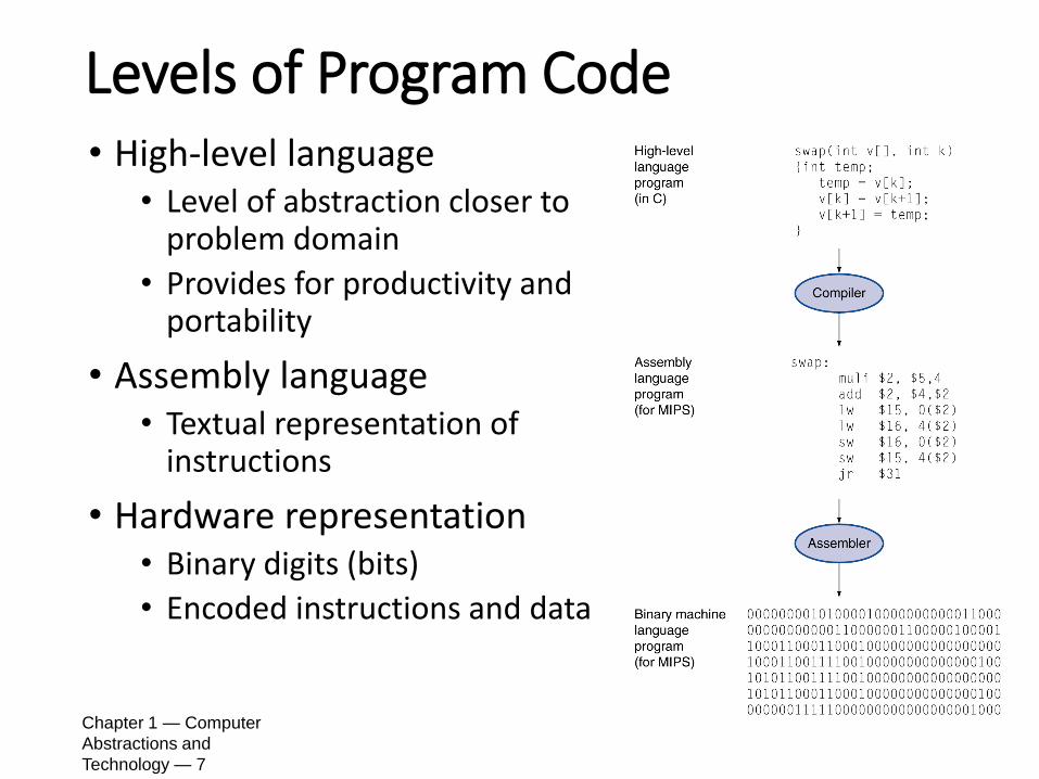
Levels of Program Code• High-level language
• Level of abstraction closer to problem domain
• Provides for productivity and portability
• Assembly language• Textual representation of
instructions
• Hardware representation• Binary digits (bits)
• Encoded instructions and data

Assembly Language
• Assembly language vs. higher-level language• Few, simple types of data• Does not specify variable type• Simple control flow: goto/jump• Assembly language programming is more difficult and error-
prone, it is machine-specific; it is longer
• Assembly language vs. machine language• Symbolic representation
• When assembly programming is needed• Speed and size (eg. embedded computer)• Time-critical parts of a program• Specialized instructions
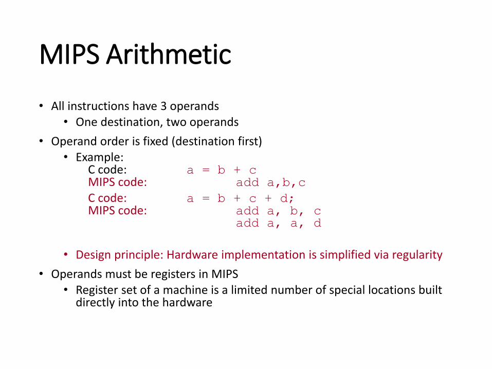
MIPS Arithmetic
• All instructions have 3 operands• One destination, two operands
• Operand order is fixed (destination first)• Example:
C code: a = b + cMIPS code: add a,b,c
C code: a = b + c + d;MIPS code: add a, b, c
add a, a, d
• Design principle: Hardware implementation is simplified via regularity
• Operands must be registers in MIPS• Register set of a machine is a limited number of special locations built
directly into the hardware

Assembly Variables: Registers
• Unlike HLL, assembly cannot use variables• Why not? Keep hardware simple
• Different operand locations for different architectures• Stack, register, memory or a mix of them• Every architecture design after 1980 uses a load-store
register architecture: ALU operands are all registers; memory can only be accessed with load/store
• Advantages of load-store register architectures• Registers are faster than memory • Registers are more efficient for a compiler to use
• Drawback: the no. of registers is predetermined• Assembly code must be very carefully put together to
efficiently use registers
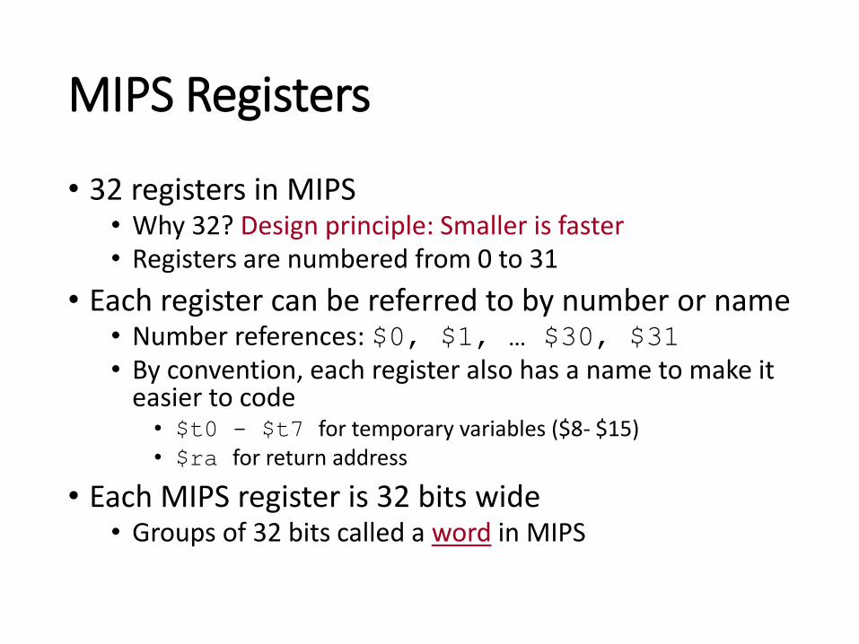
MIPS Registers
• 32 registers in MIPS• Why 32? Design principle: Smaller is faster• Registers are numbered from 0 to 31
• Each register can be referred to by number or name• Number references: $0, $1, … $30, $31• By convention, each register also has a name to make it
easier to code• $t0 - $t7 for temporary variables ($8- $15)• $ra for return address
• Each MIPS register is 32 bits wide• Groups of 32 bits called a word in MIPS

MIPS Arithmetic with Registers
• MIPS Example • C code: a = b + c
MIPS code: add $s1,$s2,$s3
• C code: a = b + c + d;
MIPS code: add $t1,$s2,$s3
add $s1,$t1,$s4
• $s0-$s7 conventionally are used for registers that correspond to variables in C/Java programs ($16-$23)

C, Java Variables vs. Registers
• In C (and most high level languages), variables declared first and given a type• Example: int fahr, celsius;
char a, b, c, d, e;
• Each variable can ONLY represent a value of the type it was declared as (cannot mix and match int and char variables)
• In assembly language, the registers have no type; operation determines how register contents are treated

MIPS Instructions
• Syntax of instructions:op dest, src1, src2• Op: operation by name • Dest: operand getting result (“destination”)• Src1: 1st operand for operation (“source1”)• Src2: 2nd operand for operation (“source2”)
• Each line of assembly code contains at most 1 instruction
• Hash (#) is used for MIPS comments• Anything from hash mark to end of line is a comment and will
be ignored• Every line of your comments must start with a #

Addition/Subtraction Example
• How to do the following C statement?a = b + c + d - e;
• Break into multiple instructions• add $t0, $s1, $s2 #temp = b + c• add $t0, $t0, $s3 #temp = temp + d• sub $s0, $t0, $s4 #a = temp - e
• Notice • A single line of C code may break up into several lines of MIPS
code• May need to use temporary registers ($t0 - $t9) for
intermediate results• Everything after the hash mark on each line is ignored
(comments)

Constant or Immediate Operands• Immediates are numerical constants
• They appear often in code, so there are special instructions for them
• Design principle: Make the common case fast
• Add Immediate:• C code : f = g + 10
• MIPS code: addi $s0,$s1,10• MIPS registers $s0, $s1 are associated with C variables f, g
• Syntax similar to add instruction, except that last argument is a number instead of a register
• How about subtraction? subi?

Constant or Immediate Operands
• There is NO subtract immediate instruction in MIPS: Why?• ISA design principle: limit types of operations that can
be done to minimum
• If an operation can be decomposed into a simpler operation, do not include it
• addi …, -X = subi …, X => so no subi
• Example• C code: f = g - 10
• MIPS code: addi $s0,$s1,-10• MIPS registers $s0,$s1 are associated with C variables f, g

Register Zero
• One particular immediate, the number zero (0), appears very often in code
• So we define register zero ($0 or $zero) to always have the value 0• Often used to move values or set constant values
• f = g (in C-language)
• add $s0, $s1, $zero (in MIPS)• MIPS registers $s0, $s1 are associated with C variables f, g
• $zero defined in hardware• Instruction add $zero,$zero,$s0 will not do anything!
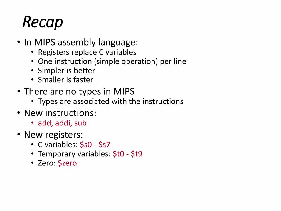
Recap• In MIPS assembly language:
• Registers replace C variables• One instruction (simple operation) per line• Simpler is better• Smaller is faster
• There are no types in MIPS• Types are associated with the instructions
• New instructions:• add, addi, sub
• New registers:• C variables: $s0 - $s7• Temporary variables: $t0 - $t9• Zero: $zero

Personal Computer
Processor
Computer
Control(“brain”)
DatapathRegisters
Memory Devices
Input
OutputLoad (from)
Store (to)
These are “data transfer” instructions…
Registers are in the datapath of the
processor; program data are in
memory, we must transfer them to the
processor to operate on them, and then
transfer back to memory when done
Anatomy of a Computer

Memory Organization
• Viewed as a large, single-dimension array
• A memory address is an index into the array• "Byte addressing" means that the index points to a byte
of memory
0
1
2
3
4
5
6
...
8 bits of data
8 bits of data
8 bits of data
8 bits of data
8 bits of data
8 bits of data
8 bits of data

Memory Organization
• Bytes are nice, but most data items use larger "words"• For MIPS, a word is 32 bits or 4 bytes
• MIPS register holds 32 bits of data• 232 bytes with byte addresses from 0 to 232-1• 230 words with byte addresses 0, 4, 8, ... 232-4
• Words are aligned: they must start at addresses that are multiples of 4
0
4
8
12
...
32 bits of data
32 bits of data
32 bits of data
32 bits of data

Specify Memory Addresses• To transfer data, we need to specify:
• Register: specify this by number ($0 - $31) or symbolic name ($s0,…, $t0, …)
• Memory address: supply a pointer/index to the byte-addressed one-dimensional array• Often, we want to be able to offset from a pointer: e.g. element A[2],
date.month
• The general format for a memory address offset(base register) specifying• A register containing a pointer to memory• A numerical offset (in bytes)
• The desired memory address is the sum of these two values• Example: 8($t0) specifies memory[$t0+8] (byte)
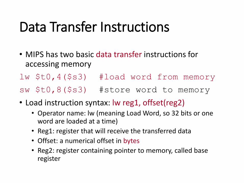
Data Transfer Instructions
• MIPS has two basic data transfer instructions for accessing memory
lw $t0,4($s3) #load word from memory
sw $t0,8($s3) #store word to memory
• Load instruction syntax: lw reg1, offset(reg2)• Operator name: lw (meaning Load Word, so 32 bits or one
word are loaded at a time)
• Reg1: register that will receive the transferred data
• Offset: a numerical offset in bytes
• Reg2: register containing pointer to memory, called base register

Data flow
Load Word Example
• Example: lw $t0,12($s0)• This instruction will take the pointer in $s0, add 12 bytes
to it, and then load the value from the memory pointed to by this calculated sum into register $t0• $s0 is called the base register
• 12 is called the offset
• Offset is generally used in accessing elements of array or structure: base register points to beginning of array or structure
Data flow
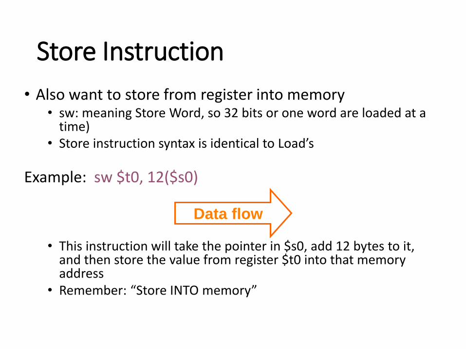
Store Instruction
• Also want to store from register into memory• sw: meaning Store Word, so 32 bits or one word are loaded at a
time) • Store instruction syntax is identical to Load’s
Example: sw $t0, 12($s0)
• This instruction will take the pointer in $s0, add 12 bytes to it, and then store the value from register $t0 into that memory address
• Remember: “Store INTO memory”

Example
• C code: A[12] = h + A[8];MIPS code:
lw $t0, 32($s3) # base addr of array A in $s3
# 1 array element is 4-byte
add $t0, $s2, $t0 # h is associated with $s2sw $t0, 48($s3) # offset=12*4=48
• Can refer to registers by name (e.g., $s2, $t2) instead of number
• Store word has destination last• Remember arithmetic operands are registers, not
memory!• Can’t write: add 48($s3), $s2, 32($s3)

Pointers vs. Values
• Key concept: a register can hold any 32-bit value• That value can be a signed int, an unsigned int, a pointer
(memory address), and so on
• If you write add $t2,$t1,$t0, then $t0 and $t1 better contain values
• If you write lw $t2,0($t0), then $t0 better contains a pointer
• Don’t mix these up!
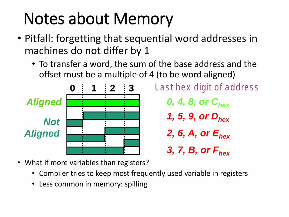
Notes about Memory• Pitfall: forgetting that sequential word addresses in
machines do not differ by 1• To transfer a word, the sum of the base address and the
offset must be a multiple of 4 (to be word aligned)
• What if more variables than registers?
• Compiler tries to keep most frequently used variable in registers
• Less common in memory: spilling
0, 4, 8, or Chex
Last hex digit of address
1, 5, 9, or Dhex
2, 6, A, or Ehex
3, 7, B, or Fhex
0 1 2 3
Aligned
Not
Aligned

Outline
• Introduction to assembly language
• MIPS instruction set architecture• MIPS basic instructions
• Arithmetic instructions: add, addi, sub
• Data transfer instructions: lw, sw
• Control instructions
• Logical operations
• MIPS instruction format
• Encoding/decoding assembly code

Bitwise Operations
• Up until now, we’ve done arithmetic (add, sub,addi ), memory access (lw and sw), and branches and jumps
• All of these instructions view contents of register as a single quantity (such as a signed or unsigned integer)
• New perspective: view register as 32 raw bits rather than as a single 32-bit number• We may want to access individual bits (or groups of bits)
rather than the whole
• Two new classes of instructions: logical & shift operations
Logical Operators
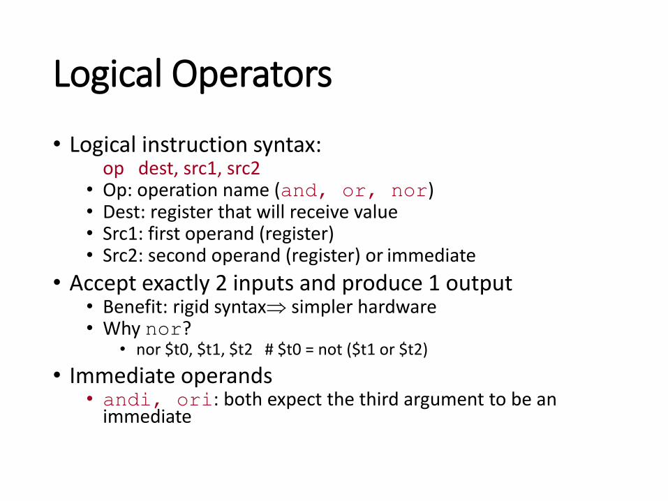
• Logical instruction syntax:op dest, src1, src2
• Op: operation name (and, or, nor)• Dest: register that will receive value• Src1: first operand (register)• Src2: second operand (register) or immediate
• Accept exactly 2 inputs and produce 1 output• Benefit: rigid syntax simpler hardware• Why nor?
• nor $t0, $t1, $t2 # $t0 = not ($t1 or $t2)
• Immediate operands • andi, ori: both expect the third argument to be an
immediate
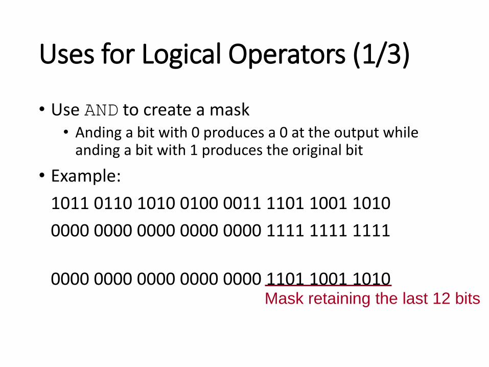
Uses for Logical Operators (1/3)
• Use AND to create a mask• Anding a bit with 0 produces a 0 at the output while
anding a bit with 1 produces the original bit
• Example:
1011 0110 1010 0100 0011 1101 1001 1010
0000 0000 0000 0000 0000 1111 1111 1111
0000 0000 0000 0000 0000 1101 1001 1010Mask retaining the last 12 bits

Uses for Logical Operators (2/3)
• A bit pattern in conjunction with AND is called a mask that can conceal some bits• The previous example a mask is used to isolate the
rightmost 12 bits of the bit-string by masking out the rest of the string (e.g. setting it to all 0s)
• Concealed bits are set 0s, while the rest bits are left alone
• In particular, if the first bit-string in the above example were in $t0, then the following instruction would mask it:
andi $t0,$t0,0xFFF

Uses for Logical Operators (3/3)
• Similarly effect of OR operation• Oring a bit with 1 produces a 1 at the output while oring
a bit with 0 produces the original bit
• This can be used to force certain bits to 1s
• Example• $t0 contains 0x12345678, then after this instruction:
ori $t0, $t0, 0xFFFF
• $t0 contains 0x1234FFFF (e.g. the high-order 16 bits are untouched, while the low-order 16 bits are forced to 1s)
0011 0100 0101 0110 0111 1000 0000 0000
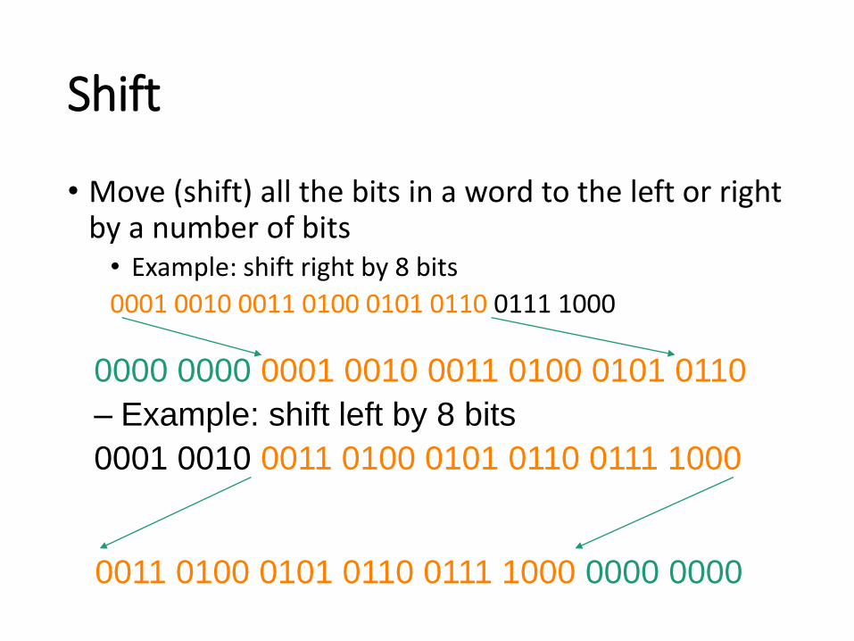
Shift
• Move (shift) all the bits in a word to the left or right by a number of bits• Example: shift right by 8 bits
0001 0010 0011 0100 0101 0110 0111 1000
0000 0000 0001 0010 0011 0100 0101 0110
– Example: shift left by 8 bits
0001 0010 0011 0100 0101 0110 0111 1000

Logical Shift Instructions
• Shift instruction syntax:op dest, reg, amt
• Op: operation name• Dest: register that will receive value• Reg: register with the value to be shifted• Amt: shift amount (constant < 32)
• MIPS logical shift instructions:• sll (shift left logical): shifts left and fills emptied bits with 0s• srl (shift right logical): shifts right and fills emptied bits with
0s• MIPS also has arithmetic shift instructions that fills with the
sign bit