assembly ltc-f20 - levil...
TRANSCRIPT

1
Assembly LTC-F20
Safety awareness, please be aware of your environment at all times. Some items like extension cords, air hoses etc. could be a trip hazard. Screws, FOD any item on the floor like fluids from spills could be a potential slip hazard. Lifting heavy objects over 50 pounds, use a 2 person lift procedure or/and lifting equipment if available. Wear the required safety equipment and report/or resolve any unsafe situations.
• Safety glasses for drilling, taping, cutting materials, sanding, use of any pneumatic tools, machinery that create a hazard including dust, chips and FOD, handling corrosive fluids and solvents that could cause eye irritation including sealants, adhesives, acetone and grease.
• Latex gloves for handling corrosive fluids and solvents that could irritate the skin including adhesives, acetone and sealants.
• Dust mask and/or respirator if applicable for any sanding, polishing and application of paint solvents.
• Steel toe shoes are required at all times in all production areas
Tools:
• 3 mm Allen Wrench • 4 mm Allen Wrench • 5 mm Allen Wrench • Oil Canister • Acetone • Paper Towel
• Parallel • Guideway Cart • Dial Indicator • 3 C-clamps • Iron Plate • Alignment table

2
Procedure: Inventory: 1. Check for threaded holes at the ends of side and center
bases. If not there, use M6x1.0 tap to thread the ends of all bases. Clean all bases with acetone. Screw in M6X10 button heads to the ends of the three center bases and the tops of side bases.
• 1 P5-TL20 base top (1000116) • 2 P7-TL20 base side (1000118) • 3 P6-TL20 base center
(1000117) • 16 M6X10 button heads
(1100024)
2. Clean Base Z’s guideway channels and rails with acetone. Apply a coat of oil to rails and install them.
• 1 P3-TL20 base Z (1000090) • 2 TL-20 Z Guideway Rails
(1200021) • 12 M5X25 socket screws
(1100022)
3. Clean base X’s guideway channels and rails with acetone. Apply a coat of oil to rails and install them. The end of the guideway rail should line up with lower edge of the base.
• 1 P8-TL20 base X (1000096) • 2 TL-20 X Guideway Rails
(1200020) • 8 M5X25 socket screws
(1100022)
4. Inspect guideway rails have been installed properly by checking them with a dial indicator mounted on a railway cart. Max error allowed per 100 mm is ±0.02.
5. Pass indicated screws through base Z and base Z back, screwing T-nuts to ends of screws. Slide center bases through T-nuts on base Z, tighten one screw in each center base to prevent sliding once put in place. Then slide base Z back into base Z assembly.
• 1 P4-TL20 base Z back (1000092)
• 25 M6X25 socket screws (1100031)
• 20 M6X16 socket screws (1100029)
• 36 T-nuts (1100061)
6. Slide side bases through T-nuts in both front and back Z bases as well as through button head screws in center bases. Finally slide top base through T-nuts and button heads at the top of side bases.
7. Slide last center base in between two base Z lower using M6X12 screws and T-nuts. Flip machine upside down and slide base Z lower assembly into place, with crew countersinks pointing up towards the legs. Slide four T-nuts through the outer channels of each side base and mount machine legs.
• 2 P1-WL4C machine leg (1000001)
• 2 P2-TL20 base Z lower (1000090)
• 18 M6X12 socket screw (1100026)
• 24 T-nuts (1100061) • 4 M6X40 socket screws
(1100082)

3
8. Make sure machine leg support has corresponding serial number before mounting it using M6X12 crews and free T-nuts previously placed on side bases. The serial number should be on the left side of the machine.
• 2 P1-TL20 leg support (1000089)
• 4 M6X12 socket screw (1100026)
• 2 M6X16 socket screws (1100029)
9. Use a parallel to make sure the right side base is flat against base Z between the two guideway rails. Tighten all screws accordingly.
10. Install guideway carts to base X and table X. Metal side of carts should face up in base X, and face right on table X. Once all carts are installed slide base X into base Z guideway rails and table X into base X guideway rails.
• 1 P9-TL20 table X (1000097) • 16 M4X16 socket screws
(1100009) • 16 M4X25 socket screws
(1100011) • 8 Guideway Rail Carts
(1200015)
11. Align machine’s XZ axis using aligning table and dial indicator.
12. Install ball screws into base X and table X.
13. Mount Pragati turret to table X and align the horizontal and vertical axes with dial indicator. Double stack washers on the top right of turret.
• 1 Pragati turret (1200027) • 4 M8X30 socket screws
(1100035) • 5 M8 blue washers (1100052)
14. Mount 5/16” dowel pins to base Z with red Loctite. Make sure spindle base is correct height and screw it into base Z. Insert ¼” dowel pins into corresponding spindle assembly and mount to spindle base. Screw in chuck plate and chuck onto spindle for alignment.
• 4 5/16” dowel pins (1100054) • 2 ¼” dowel pins (1100053) • 1 P12-TL20 spindle base
(1000100) • 4 M8 flat blue washers
(1100052) • 4 M8X35 hex screws
(1100119) • 4 M6 set screws (1100043) • 4 M8X130 socket screws
(1100039)

4
Ball Screw LTC-F20
Tools:
• 2 mm Allen Wrench • 4 mm Allen Wrench • 5 mm Allen Wrench • Grease • Oil • Red Loctite
• Scissors • Hand Drill • 4.3 mm Drill Bit • 5.1 mm Drill Bit • 6.0 Drill Bit • M6X1.0 Tap
Procedure: Inventory: 1. Clean mating surfaces on ball screw and nut base.
Insert X and Z Ball Screws into Accu Tech ball nut bases and screw them in tightly.
• 1 TL-F20 X Ball Screws (1200006)
• 1 TL-F20 Z Ball Screws (1200007)
• 2 P53-WL4C nut base accu tech (1000054)
• 8 M5X16 socket screws (1100019)
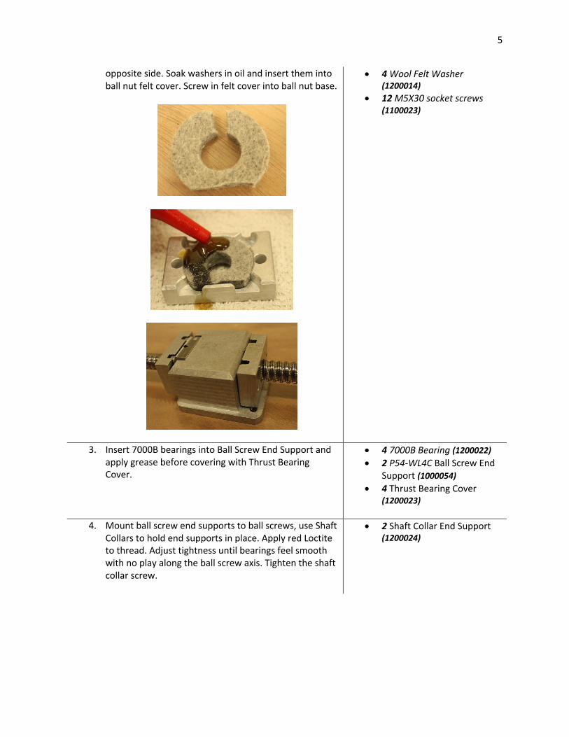
2. Cut about 3 mm off the wool washer tangent to the circle and another cut through the washer on the
• 4 P55-WL4C ball nut felt cover (1000055)
5
opposite side. Soak washers in oil and insert them into ball nut felt cover. Screw in felt cover into ball nut base.
• 4 Wool Felt Washer (1200014)
• 12 M5X30 socket screws (1100023)
3. Insert 7000B bearings into Ball Screw End Support and apply grease before covering with Thrust Bearing Cover.
• 4 7000B Bearing (1200022) • 2 P54-WL4C Ball Screw End
Support (1000054) • 4 Thrust Bearing Cover
(1200023)
4. Mount ball screw end supports to ball screws, use Shaft Collars to hold end supports in place. Apply red Loctite to thread. Adjust tightness until bearings feel smooth with no play along the ball screw axis. Tighten the shaft collar screw.
• 2 Shaft Collar End Support (1200024)
6
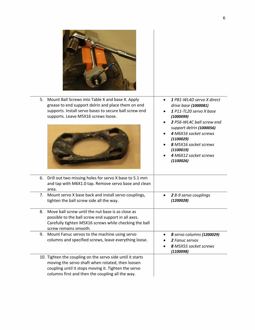
5. Mount Ball Screws into Table X and base X. Apply grease to end support delrin and place them on end supports. Install servo bases to secure ball screw end supports. Leave M5X16 screws loose.
• 1 P81-WL4D servo X direct drive base (1000081)
• 1 P11-TL20 servo X base (1000099)
• 2 P56-WL4C ball screw end support delrin (1000056)
• 4 M6X16 socket screws (1100029)
• 8 M5X16 socket screws (1100019)
• 4 M6X12 socket screws (1100026)
6. Drill out two missing holes for servo X base to 5.1 mm and tap with M6X1.0 tap. Remove servo base and clean area.
7. Mount servo X base back and install servo couplings, tighten the ball screw side all the way.
• 2 8-9 servo couplings (1200028)
8. Move ball screw until the nut base is as close as possible to the ball screw end support in all axes. Carefully tighten M5X16 screws while checking the ball screw remains smooth.
9. Mount Fanuc servos to the machine using servo columns and specified screws, leave everything loose.
• 8 servo columns (1200029) • 2 Fanuc servos • 8 M5X55 socket screws
(1100098) 10. Tighten the coupling on the servo side until it starts
moving the servo shaft when rotated, then loosen coupling until it stops moving it. Tighten the servo columns first and then the coupling all the way.
7
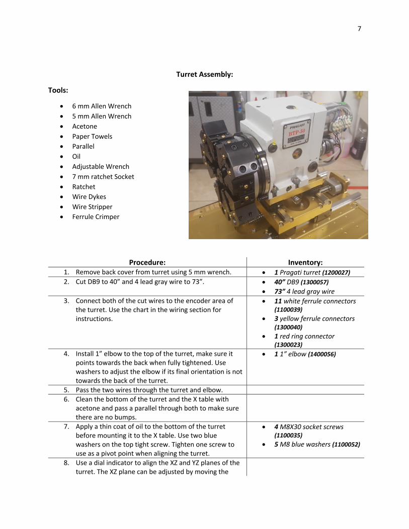
Turret Assembly:
Tools:
• 6 mm Allen Wrench • 5 mm Allen Wrench • Acetone • Paper Towels • Parallel • Oil • Adjustable Wrench • 7 mm ratchet Socket • Ratchet • Wire Dykes • Wire Stripper • Ferrule Crimper
Procedure: Inventory: 1. Remove back cover from turret using 5 mm wrench. • 1 Pragati turret (1200027) 2. Cut DB9 to 40” and 4 lead gray wire to 73”. • 40” DB9 (1300057)
• 73” 4 lead gray wire 3. Connect both of the cut wires to the encoder area of
the turret. Use the chart in the wiring section for instructions.
• 11 white ferrule connectors (1100039)
• 3 yellow ferrule connectors (1300040)
• 1 red ring connector (1300023)
4. Install 1” elbow to the top of the turret, make sure it points towards the back when fully tightened. Use washers to adjust the elbow if its final orientation is not towards the back of the turret.
• 1 1” elbow (1400056)
5. Pass the two wires through the turret and elbow. 6. Clean the bottom of the turret and the X table with
acetone and pass a parallel through both to make sure there are no bumps.
7. Apply a thin coat of oil to the bottom of the turret before mounting it to the X table. Use two blue washers on the top tight screw. Tighten one screw to use as a pivot point when aligning the turret.
• 4 M8X30 socket screws (1100035)
• 5 M8 blue washers (1100052)
8. Use a dial indicator to align the XZ and YZ planes of the turret. The XZ plane can be adjusted by moving the

8
turret around a pivot point. The YZ plane can be adjusted by adding shims to the bottom of the turret.
9. Make sure all screws are tight.
LS-32 Spindle Assembly Tools:
• 4 mm Allen Wrench • 6 mm Allen Wrench • KM6 Wrench • KM12 Wrench • Blue Loctite • Oil • High Speed Grease • Syringe • Caliper • Rough & Fine Sandpaper • Mineral Spirits • Cotton Balls • Beaker
Procedure: Inventory: 1. Check spindle nose for correct tolerance (95+0.02) mm.
Test fit bearing into nose to verify. Use honing tool for hand drill and oil if tolerance is not met.
• 1 LS-32 Spindle nose (1700001)
2. Check all bearings, magnet, and magnet holder slide into the spindle shaft. Hone shaft in the manual lathe with fine sand paper if anything doesn’t fit.
• 1 LS-32 Spindle shaft (1700004)
3. Break spacer bearing and sand to size (inner race 0.005-0.01 mm smaller than outer race). Each individual race must have a maximum height error of 0.005 mm along its circumference.
• 1 Spacer Bearing (1700010)
4. Apply red Loctite to magnet holder and install on motor magnet, let it dry while mounted on a spindle shaft to ensure it dries straight.
• 1 Magnet holder (1700016) • 1 Motor Magnet (1700007)
5. Once all tolerances are met, clean spindle shaft and nose with acetone. Blow parts with compressed air to get rid of any remaining imperfections.
6. Set keys on spindle shaft with red loctite, use clamp to push them in. Keys are used to keep the magnet from spinning.

9
7. Clean Nachi precise bearings with mineral spirits by soaking a cotton ball and dripping the inside of the bearing. Use a beaker to catch the used spirit. Use compressed air to dry the bearings.
• 1 Nachi bearing set (1700002)
8. Apply a small amount of thermal grease with a syringe, just enough to evenly cover both races and ball bearings.
9. Assemble the two precise bearings and bearing spacers into the spindle shaft. The arrows on the outside of the two precise bearings should point towards each other.
10. Install KM12 nut with flat side facing up and small amount of blue Loctite on threads.
• 1 KM12 nut (1700005)
11. Apply a thin coat of oil to the inside of the spindle nose and insert spindle shaft assembly into it. Push the assembly in very carefully to avoid it from getting jammed.
12. Install bearing support to spindle nose. Tighten screws and check the spindle spins smoothly.
• 1 bearing support (1700011) • 4 M5X10 socket screws
(1100014) 13. Mount spindle assembly sideways on a vise, place dial
indicator at the tip of the shaft and rotate the spindle. The max error allowed is 0.02mm wobble. Once the tolerance is met remove one screw at a time and apply blue loctite before re-installing.
14. Insert motor magnet with holder to shaft. 15. Install two upper bearings. Finally screw in KM6 nut
with a little blue loctite, tighten all the way. • 1 KM6 nut (1700006) • 2 upper bearings (1700003)
16. Grab a lathe winding and wrap the red, white, and black wires with 8” of heat shrink starting from the base.
• 1 Lathe Winding (1700007)
17. Take an LS-32 spindle headstock and test fit the upper bearing to ensure the tolerance is met. Hone if necessary.
• 1 LS-32 headstock (1700015)
18. Clean spindle headstock with acetone, use compressed air to dry.
19. Measure the closest distance between the largest bore at the bottom and the back face of the headstock. This distance should be around 6.0mm and it’s needed to calculate the height of the spindle base, call it U.
20. Insert the winding into the headstock, make sure the wires don’t stick out in the middle of the winding to avoid damage from rubbing against the motor magnet.
21. Once winding is pushed all the way in, insert M6X10 set screws with blue loctite to hold it in place.

10
22. Dab the upper bearings with a little blue Loctite to prevent slipping when the spindle is on.
23. Mount spindle assembly. Avoid hitting the magnet against the winding on the way in.
• 4 M8X25 socket screws (1100068)
24. Rotate the spindle to make sure it feels smooth, a kink or uneven tightening of screws might cause it to get rough.
25. Measure the height from the X table to the Z base, it should be around 94.5mm. This measurement is also used to calculate the height of the spindle base, call it W. The final equation is base height = W – U – 7.43
26. Cut the spindle base to the calculated height, make sure the top and bottom faces are parallel with a max error of 0.02mm.
• 1 Spindle Base (1000100)
27. Pass a parallel through the spindle base holes to make sure there are no bumps, do the same for the mounting holes in the Z base.
28. Install 5/16” steel dowels into Z base with red loctite. • 4 5/16” steel dowels (1100054)
29. Clean spindle base and mounting area on the Z base with acetone.
30. Screw in spindle base to Z base, tighten only one screw to use as a pivot point for alignment.
• 4 M8X30 hexagonal heads (1100119)
• 4 M8 blue washers (1100051) 31. Insert ¼” steel dowels in the back of the spindle
headstock with red loctite. • 2 ¼” steel dowels (1100053)
32. Install spindle to spindle base and tighten M8X130 screws all the way.
• 4 M8X130 socket screws (1100039)
33. Mount chuck plate and alignment chuck on the spindle and insert the alignment rod. Use the dial indicator on the side of the rod to measure the XZ plane error.
• 4 M6X20 socket screws (1100030)
• 3 M8X40 socket screws (1100037)
34. Pick an extremity of the alignment rod and rotate the spindle, adjust the dial so that the center of the wobble is zero. Move to the other side of the rod and measure the center of the wobble again, the difference is the error in the XZ plane. Adjust the spindle base as needed.
35. Once the XZ plane is aligned with a max error of 0.02mm per 100mm, tighten the hexagonal screws holding the spindle base, make sure to tighten them gradually while checking the error to avoid making the error worse,
36. When the screws are all tight, add M8 set screws to the sides of the spindle base with blue loctite and tighten them gently, alternating between them to avoid
• 4 M8X16 set screws (1100044)

11
movement of the spindle base. Check the plane one last time to make sure it did not move.
37. Move the dial indicator to the top of the rod and repeat the alignment process for the YZ plane. If there is error in the plane, loosen the long M8X130 screws and add shims between the spindle headstock and base.
38. After aligning the two planes, remove the alignment rod and replace it with the radial dial. Use it to compare the height of the spindle to the turret tool holders. Adjust the turret in the X axis so that the dial reading is the same on both sides of the tool holder and then measure the top, the difference from the sides is the error in height.
39. The spindle base is intentionally made a little higher so that the turret height can be adjusted if there is an error between them. Fix the error by adding shims under the turret.
40. Once the alignment is done, remove the chuck and chuck plate from the spindle.

12
Lathe Tub Assembly
Tools:
• 3 mm Allen Wrench • 4 mm Allen Wrench • 5 mm Allen Wrench • 10 mm Wrench • Acetone • Paper Towels • Grease • Wire dykes • Silicone • Hand drill • Chamfer drill bit
Procedure: Inventory: 1. Take a lathe tub and drill out the three screw holes
closer to the guideway rails on the top right side of the tub. Use the chamfer drill bit with the slow speed setting.
• 1 Lathe tub (1400014)
2. Clean the Z base and apply white grease to the gasket channel. Cut ring cord to fit the channel and insert it, adding another coating of grease over the cord.
• 30.5” ring cord (1400003)
3. Clean the area of the tub that will go over the gasket with acetone.
4. Mount the tub on the machine, make sure ring cord doesn’t come off the channel while adjusting tub position.
5. Screw tub to the machine, use conical screws for the holes that were chamfered in step 1.
• 12 M5X8 button heads (1100116)
• 3 M5X10 conical screws (1100109)
6. Stand machine upright. 7. Take Door and mount door support bracket and piston
base. Make sure piston base is on the side of the door • 1 Door (1400023)

13
with the two holes for the door sensor magnet. The 5/16” hole in the piston base should face up when the door is open.
• 1 Door support bracket (1000061)
• 1 Piston Base (1000107) • 2 M5X10 conical screws
(1100109) 8. Take door handle screws that come in the packaging
and cut them half way before using them. Put a plastic washer on each side of the door for the screws holding the handle.
• 1 Door handle kit (1400024) • 4 M5 plastic washers
(1100047)
9. Mount door hinges onto the door, leave loose. Install door assembly on the tub, apply black RTV silicone to screws holding the hinges before tightening the nuts.
• 4 M5X12 conical screws (1100110)
• 4 M5X16 conical screws (1100111)
• 2 Door hinges (1400019) • 8 M5 lock-nuts (1100057)
10. Install door piston. • 1 5/16” nut (1100059) • 1 pneumatic piston
(1400052) 11. Use RTV silicone to seal the edges of the tub in the
working area. Also apply silicone to edges of door support brackets.

14
Light Enclosure Assembly Tools:
• Wire Cutter • Wire Stripper • Wire Crimper • Soldering Station • Silicone • Heat Gun • Hand Drill • 4.3mm Drill Bit
Procedure: Inventory: 10. Take LED strip and cut it to 12”, take care to leave some
solder on both sides of the cut. • 12” LED (1300058)
11. Cut semicircular plastic piece to 12” and sand until it fits snuggly into glass tube.
• 12” semicircular plastic (1300059)
• 1 pre-cut glass tube (1300060)
12. Clean semicircular plastic with Windex and glue on LED strip.
13. Cut two white AWG 20 wires and one blue AWG 20 wire to 12”. The LED has three leads, solder the white wires to the outer two leads and the blue wire to the center lead.
14. Drill out one of the two end caps with a 4.3mm drill bit to pass the LED wires through.
• 2 plastic caps (1300061)

15
15. Insert the semicircular plastic with LED into the glass tube and apply silicone to both ends before closing the tube with the caps.
16. Test the light with a 24V DC power supply.
Wiring LTC-F20 Tools:
• 3 mm Allen Wrench • 4 mm Allen Wrench • 5 mm Allen Wrench • Flat Screw Driver • Wire Cutter • Wire Stripper • Wire Crimper • Wire Peeler • Molex Pin Tool Crimper • Ferrule Crimper • Soldering Station • Drill • 4.3mm Drill Bit
Procedure: Inventory: 1. Cut wires to desired lengths listed in
inventory section. The numbers in parenthesis are sub-divisions of that wire.
• 2 Power cords (1300005) • 1 DB9 (1300057) • (6 wire) Gray - 68” (1300046) • Vafam – 41” (1300047) • (Black & Red) Coleman – 271”
(62)(60)(84)(65) (1300050) • 1” ID hose for wires – 37.5” (13.5)(24)
(1300071) • 1/2” conduit for turret – 19” (1300072) • Ribbon Cable – 10” (1300048)

16
• 3 wire gray – 257” (61)(77)(42)(27)(40)(10) (1300045)
• Yellow Hose – 83” (1400027) • Blue Hose – 18” (1400036) • Black AWG 12 – 24” (12)(12) (1300053) • Black AWG 14 – 54” (30)(4)(20)
(1300055) • Black AWG 20 – 3” • Gray AWG 14 – 58” (30)(12)(12)(4)
(1300054) • White AWG 14 – 24” (20)(4) (1300053) • White AWG 20 – 15” (1300052) • Blue AWG 14 – 4” (1300082) • Blue AWG 20 – 43” (14)(14)(15) • Red AWG 14 – 20” (1300083) • Ground – 62” (16)(12)(20)(10)(4)
(1300056)
2. Grab a control housing and drill out 3mm holes to 4mm. Deburr all holes that were drilled.
• 1 Control Housing
3. Locate CNC panel and install into control housing. This is the panel with the screen.
• 1 CNC Panel • 4 M4 Lock-nuts (1100058) • 4 M4X10 socket screws. (1100007)
4. Take operating panel and fit to control housing. This is the keyboard.
• 1 Operating Panel • 4 M4 Lock-nuts (1100058) • 4 M4X10 socket screws (1100007)
5. Install I/O panel into control housing. This panel contains machine operation buttons.
• 1 I/O panel • 4 M4 Lock nuts (1100058) • 4 M4X10 socket screws (1100007)
6. Install Manual Override panel into control housing. This panel includes the emergency button, feed and RPM manual overrides.
• 6 M4X10 button heads (1100115) • 6 M4 lock-nuts (1100058)
7. Locate MPG and fit to control housing using the screws, washers, and nuts provided by packaging.
• 1 MPG
8. Install 0/24V bus into the control housing. Use a screwdriver to hold nuts in place while tightening the screws since ratchet sockets do not reach.
• 1 0/24V Bus (1300068) • 2 M5X20 Button Heads (1100021) • 2 M5 washers (1100046)
9. Install Tower Light, keep light labels facing towards the back of the machine.
• 1 Tower Light (1300069)
10. Use ground wires to connect all the panel grounds, each panel has a designated threaded hole or screw for grounding.
11. Mount control housing to the machine’s tub. Screws should be pointing down, with the
• 4 M6X12 socket screws (1100026) • 4 M6 lock-nuts (1100056)

17
heads on the control side and the nuts on the tub side.
12. Insert grommets from control housing to tub. • 1 1” wide grommet (1500039) • 1 .5” wide grommet (1500041)
13. Take light assembly and install to the tub with the light facing down diagonally. Screws should be pointing up, with the nut on the control side.
• 2 1” clamps (1300062) • 2 M5X16 socket heads (1100019) • 2 M5 lock-nuts (1100057)
14. Take the electronics cabinet and remove the door. Give the door to machining department to make the opening for the external battery case.
• 1 electronics cabinet (1300070)
15. Use the template plate to drill out the holes on the back of the electronics cabinet.
16. Finish the lower holes with a servo driver plate.
17. Make holes to the sides of the electronics cabinet for the coolant plug, power cord anchor, and servo wire hoses.
18. Take the servo driver plate and mount the servo driver. Use the set of holes on the right side of the plate.
• 1 P14-TL20 servo driver plate (1000102)
• 1 Fanuc servo driver 19. Attach 24V power supply to power supply
base. • 1 24V Power Supply (1500009) • 1 P67-WL4C Power Supply Base
(1000067) • M4x12 Socket Head (1100067)
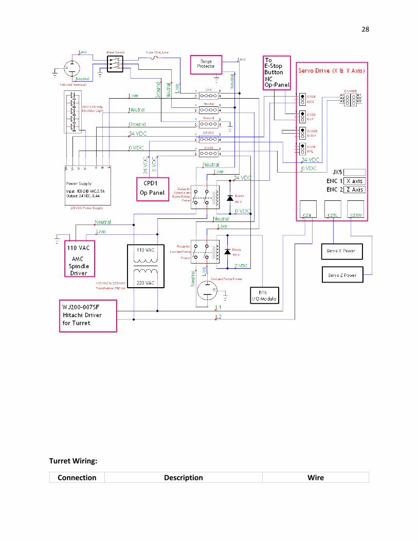
20. Take a relay plate and install fuse base, surge protector, 1.5” din rail with five terminals, two relays, power supply, and transformer. Use electronics cabinet wiring diagram for instructions on how to wire the plate. Also make connections between the servo driver plate and relay plate.
• 1 P15-TL20 relay plate (1000066) • 2 relays (1500010) • 1 ground terminal (1300095) • 1 live terminal (1300096) • 1 neutral terminal (1300097) • 1 0VDC terminal (1300098) • 1 24VDC terminal (1300099) • 2 diodes (1300015) • 1.5” din rail (1300001) • 1 Fanuc surge protector • 1 15 amp fuse base (1500014) • 1 750W transformer (1500012) • 4 M6X10 socket screws (1100025) • 1 M4X8 conical screw (1100143) • 5 M4x8 Socket head (1100006) • 1 M6X10 button head (1100024)
21. Mount servo driver and relay plates to the electronics cabinet.
• 10 M6X16 socket screws (1100029) • 10 M6 oversized washers (1100074)
22. Install the 27” 3 lead gray wire to the coolant plug. The bare wire will connect to the plug
• 1 coolant plug (1500042) • 2 M4X10 button heads (1100115)

18
with lead 1 going to live, lead 2 to neutral, and ground to ground. Connect coolant plug to the side of the electronics cabinet.
• 2 M4 lock-nuts (1100058)
23. Install power cord anchor and two 1” conduit bases for servo wires to the electronics cabinet.
• 1 cord grip (1500006) • 2 1” conduit bases (1400054)
24. Cut about 10” from the female side of the power cord. Use the female side for the spindle driver power and pass the longer male side through the power cord anchor.
25. Mount wire conduits to the bases on the electronics cabinet, the longer conduit is for the X servo and the short one for the Z servo.
26. Install electronics cabinet to the Z back base. • 6 M6X12 socket screws (1100029) • 6 M6 oversized washers (1100074)
27. Mount the machined electronics cabinet door to the cabinet and install the external battery case.
• 1 external battery case
28. Take the 77” 3 lead gray wire and connect it to the power cord with quick disconnect connectors.
• 3 blue male quick disconnect (1300021) • 3 blue female quick disconnect
(1300020) 29. Grab a main switch and install both 12” black
AWG 12 and gray AWG 14. Both black wires connect to the live leads and the gray wires connect to the neutral side.
• 1 main switch (1500008)
30. Connect the 77” gray wire from the power cord to the switch with quick disconnects. Take the 61” 3 lead gray wire and connect it to the other side of the main switch, the grounds from each gray wire connect to each other.
31. The 61” wire goes back down to the electronics cabinet to connect to the fuse and terminals. The ground connects to the power supply base.
32. Install servo wires to the servo driver and pass them through the conduits to the servos. For the X servo use a 1.5” clamp and support column to keep the conduit from rubbing against the top of the tub.
• 2 Fanuc servo wire sets • 1 1.5” hose clamp (1300064) • 1 aluminum spacer (1200030) • 1 M5X75 socket screws (1100099)
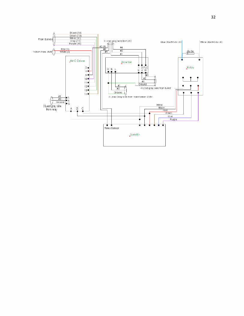
33. Install AMC driver, Hitachi inverter, and high torque relay to spindle driver plate.
• 1 AMC driver (1700013) • 1 Hitachi inverter (1500007) • 1 high torque relay (1300066) • 1 high torque relay base (1300067) • 1 P13-TL20 spindle driver plate
(1000101) • 1 M6X10 button heads (1100024)

19
• 1 1” din rail (1300001) • 6 M4X8 socket screws (1100006)
34. Mount spindle driver plate to machine tub. Make sure to use silicone on mounting screws to avoid coolant leaks.
• 4 M6X16 button heads (1100027) • 4 oversized M6 washers (1100074)
35. Use the spindle driver area diagram for wiring instructions.
36. Connect Vafam shielding to a ground wire, screw the wire to the inverter ground.
37. Press the ribbon cable with a servo module connector. Pass a 1.5”X1.5” heat shrink over the DB9 wire before connecting it and the ribbon cable to the servo encoder module. Place heat shrink over the module and apply heat.
• 1 Ribbon wire press connector (1300074)
• 1 Encoder module (1300042)
38. Adjust spindle driver switches as shown in the diagram.
39. In the control housing, solder the Vafam cable leads. The white cable to pin 5 and the red cable to pin 7 of a DB20 Fanuc connector. Also solder the DB9 to another DB20 connector, following the color scheme shown in the chart.
40. Install door sensor magnet to the machine door. Using the magnet as reference, glue the door sensor to the tub with double sided tape and a coat of silicon on the edges. Make sure sensor and tub areas are cleaned before gluing.
• 1 Door Sensor (1500016) • 1 Door Sensor Magnet (1500017)
41. Use Control Housing Connections diagram to wire the control housing area. Also reference the I/O chart.
42. Return to the electronics cabinet diagram and connect all missing wires that come from other areas of the machine.
43. Add ground wire between the servo driver and relay plate.
44. Neatly adjust and zip tie all wires in the control housing, spindle driver area, and electronics cabinet.

20
Final Touches
Procedure: Inventory: Loading Ladder and Parameters
1. Before turning on the machine for the first time, insert the memory card labeled “OI-F Lathe” and the production USB to the machine control.
2. Press and hold the two rightmost soft keys under the screen and turn on the machine, hold the buttons until the system monitor main menu pops up.
3. Go to option 7, SRAM data utility, and select it.
4. Under the sub-menu select option 2, SRAM restore. Wait for it to complete and then select option 1, end, to exit the menu.
5. Once the machine is on, press system, the soft key PMCMNT -> I/O. Use the arrow keys to navigate to the device section and select USB. Under the function section select READ.
6. Highlight the file name section and press OPRT soft key followed by LIST, select the PMC LTC-F20 V1C.MEM file.

21
7. Press EXEC, wait for ladder to load and check on the top left of the screen for a label to go from Run to Stop.
8. Go to PMCCNF -> PMC Status -> OPRT -> RUN. The label on the top left should go back to Run. The ladder must now be saved into the ROM memory.
9. Navigate back to PMCMNT -> I/O, select Flash Rom -> WRITE -> EXECUTE.
10. Repeat the process for the ladder to retrieve the IOCONF.000 file, execute it and immediately go to Flash ROM -> WRITE ->I/O CONFIGURATION -> EXECUTE.
11. The machine should now be ready for operation.
Turret Setup 12. The first step after turning on the machine should be to
set the parameters for the turret inverter, follow the chart given in the wiring section. Running the turret without setting the parameters might damage it, which is why it should be done first.
13. Run the turret clockwise and counterclockwise with the operation panel buttons while in manual mode (handle, jog), to make sure it works.
Spindle Adjustment 14. Press the emergency button and remove the power to
the spindle driver before adjusting it.
15. The spindle driver is analog and regulates the spindle speed based on voltage. 0V is the minimum speed of 0 rpm and 10V is the maximum speed of 3,200 rpm.
16. Insert voltmeter leads into pin 2 (signal gnd) and pin 4 (+ ref in) and measure DC voltage. Set speed to 3,200 rpm and make sure voltmeter reads 10V exactly, if not adjust parameter 3731. Set speed to 0 rpm and make sure voltmeter reads 0V, if not adjust parameter 3730. Go back and forth between max speed and min speed to get the right calibration because each parameter can affect the other slightly.
17. Press the emergency button and reconnect the spindle driver.
22
18. Rotate the current limit screw clockwise until an audible click is heard.
19. Run the spindle at 0 rpm, If the spindle rotates, adjust the test offset screw in the spindle driver with a flat screwdriver until it stops.
20. Use the green voltmeter with the clamp over the live wire feeding the driver power to measure current in the 20 amp range. Rotate the loop gain screw clockwise until it reaches about 12 amps where the spindle overload sensor will set off an alarm. Set the loop gain by rotating the screw counterclockwise two full rotations from where it set off the alarm.
21. If the spindle runs correctly, mount the encoder base with the sensor pointing straight up.
• 1 encoder base (1600018) • 2 M3X6 button heads
(1100004) 22. The encoder disks need to be cut in the green lathe to
fit the spindle shaft, make sure to remove set screws before cutting.
23. Install 1000 line encoder disk and encoder sensor, make sure the encoder disk in centered in the sensor. Tighten the disk set screws.
• 1 1000 line encoder disk (1600018)
• 1 encoder sensor (1600018)
24. Rotate the spindle by hand and check that the encoder disk does not wobble inside the sensor. If it does, loosen set screws and try to straighten it out before securing it again.
25. Install encoder chip to encoder sensor. Press a connector on each side of the ribbon cable and connect it to the encoder chip.
• 1 encoder chip (1600018) • 2 ribbon cable press
connector (1300074)
26. Connect the other side of the ribbon cable to the encoder module along with the DB9. Heat shrink the module.
• 1 encoder module (1300042)
27. The control should be able to read the spindle speed now. Put on the encoder cover over the disk with the screws provided in the kit.
• 1 encoder cover (1600018)
28. Install the water plug to the end of the spindle shaft. The plug works by getting compressed between the two washers inside the shaft. Use a 4 mm Allen wrench
• 1 rubber plug (1700027) • 1 M5X25 socket screw
(1100022) • 1 M5 washer (1100046)

23
on the back and a ratchet with 8 mm socket from the front.
• 1 oversized M5 washer (1100048)
29. Set the spindle speed to 500 rpm and check the spindle speed reading on the screen, if the numbers do not match, rotate the ref in gain screw in the spindle driver until they are the same.
30. Clean spindle cover with acetone and apply grease to the gasket channels. Insert ring cord into gasket channels and spread the grease over the cords.
• 1 P10-TL20 spindle cover (1000098)
31. Clean inside of the tub where the spindle cover will go and install the cover. Use silicone in the screw holes to prevent leaks into the inverter area.
• 8 M5X20 button heads (1100021)
• 8 oversized M5 washers (1100048)
Cutting Spindle 32. The spindle is now cut to improve alignment. Mount
cutting tool to tool holder 1 in the turret, make sure the tool sticks out the minimum amount possible to minimize vibrations.
33. Using handle mode and 0.01 mm increments, touch off the Z face of the spindle and go into tool offsets -> tool 1 Z -> press 0 -> measure.
34. Retract the tool and do the same for the X face, but instead of pressing 0, press 60 -> measure.
35. Mark the outside of the spindle with permanent marker to make it easier to tell where the tool has cut.
36. Plug the air into the spindle to avoid shavings from entering the assembly.
37. Run the spindle cut program until all the marker marks have disappeared from the front face and the diameter has reached 60-0.02 mm. Check that the chuck base fits snuggly on the spindle.
• 1 chuck base (1700019)
38. Clean spindle with acetone, make sure no shavings are wedged in the nose. Apply grease to the spindle nose cover and install it. Make sure the cover has the coolant outlet hole facing down.
• 1 spindle nose cover (1700026)
• 6 M4X6 button heads (1100005)
39. Run a parallel through the chuck base holes to check for bumps, clean the base and install it.
• 8 M6X20 socket screws (1100030)

24
40. Mark the chuck plate with a marker to prepare it for
cutting. Retract the tool a little more to minimize vibrations.
41. In MDI mode make the program: T0101; G96 S200 M4; And press cycle start.
42. Touch off the two faces that make contact with the chuck and set them to zero in relative position. Cut the face for the bottom of the chuck until the markings are gone and the diameter to 70-0.02 mm.
43. Install the chuck to the base, it should fit snuggly. • 1 chuck (1700018) • 3 M8X50 socket screws
(1100102) 44. Use dial indicator to check the run out of the chuck, it
should not exceed 0.02 mm.
45. Apply RTV silicone to the sides of the spindle cover.
Setting Home Position 46. Set the machine’s home position. For the Z axis, move
the turret so it’s about 2 mm away from the chuck, set that as -137.5 in relative position (this is the over-travel limit), and use handle mode to move to 0 mm. Go to parameter 1815.4 and change the 0 to 1 for Z.
47. The X axis home is set by putting the radial dial on its base and mounting it to the chuck. Adjust the turret height so that the top and bottom of each tool holders measure the same in the dial. Write down the X position for each tool holder and calculate the average. Set the average as a negative number in relative position and move up to 0 mm. Go to parameter 1815.4 and change the 0 to 1 for X.
Final Details 48. Run the machine warm up program for 15 hours to
make sure everything works correctly.
49. Plug the coolant outlet from the tub and fill it up with water for a few hours while the warm up runs to make sure there are no leaks.
25
50. Check the coolant plug is not reversed by plugging in the green tester and turning on the coolant. The tester lights will tell you if it is correct.
51. After running the machine for 15 hours, check the ball screws and couplings for any loose screws.
52. Check the ball screw end support pillows are working correctly by setting the dial indicator over the bearing covers and moving each axis, the bearings should not wobble more than 0.03mm.
53. Adjust the backlash of each servo with parameter 1851, set the dial against the turret and move it in 0.01 intervals. Move about 0.1mm one way and then retract it 0.01mm and make sure it moves the same amount in the dial as in the control.
54. Clean outside of tub with acetone where the stickers will be placed. Install Levil logo to the control housing above the MPG. The LTC-F20 sticker goes to the left of the door, lined with the top of the door. The axis sticker is below the LTC-F20, about 2” away from the door. The eye protection and moving parts can crush warnings will go under the axis sticker. The electrical hazard, 110V and coolant stickers go on the electronics cabinet. Another electrical hazard sticker will go on the side panel. Finally the 90 PSI sticker will go above the air sensor on the back of the tub.
55. Go to System -> PMCMNT -> Keep Relay and turn off the overrides for the door and air sensors by changing the 1’s to 0’s. Make sure the air sensor works by setting off the alarm when the air goes below 85 PSI. Also test the door sensor by opening the door in the middle of a program to make sure it stops.
56. Install Ethernet base and main switch to the control housing back cover. Plug an Ethernet cable from the control to the base and make sure the replacement fuses are taped inside the control housing. Put the cover on.
• 1 Ethernet cable (1500047) • 1 control housing back cover
(1500003) • 1 Ethernet base (1500046) • 16 M4X8 socket screws
(1100006) 57. Clean the side cabinet with acetone and line the sides
with shielding.
26
58. Clean inside of side panel with acetone and mount shielding, cut to fit the inner area. Make sure there are no tools in the side cabinet before closing it with the side panel.
• 1 side panel (1400014) • 12 M5X8 button heads
(1100116)
59. Install the coolant inlet hose to the top of the machine, strap it with double sided tape zip ties.
60. Oil the guideway rails before mounting the ball screw covers.
• 1 X axis top cover (1400018) • 1 Z axis left cover (1400016) • 1 Z axis right cover
(1400017) • 7 M5X8 button heads
(1100116) Backing Up Machine
61. Take a Levil USB from the tooling cabinet and the lathe’s memory card and plug them to the control to do the backups.
62. Repeat steps 2-3, under the sub menu, choose option 1, SRAM backup. Wait for the control to finish backing up then select option 1, end, to exit the menu.
63. Once the machine is on, press system, the soft key PMCMNT -> I/O. Use the arrow keys to navigate to the device section and select USB. Under the function section select WRITE.
64. Highlight the file name section and press OPRT soft key followed by LIST, select the PMC LTC-F20 V1C.MEM and IOCONF.000 files.
65. In edit mode, go to System -> PARAMETERS -> OPRT -> F OUTPUT -> EXEC.
66. Go to the computer and make a new file under client documents for the machine being backed up. Make a copy of all the files in the USB and memory card. Also save the SRAM backup from the memory card into the USB as well as the user manuals and required programs. The USB will leave with the machine.
67. Go over the check list jobs to make sure no steps have been skipped.

27
Wiring Diagrams
Electronic Cabinet Wiring:
28
Turret Wiring:
Connection Description Wire

29
1 Bit 1 Purple 2 Bit 2 Gray 3 Bit 3 Brown/Black 4 Bit 4 Green 5 Strobe White 6 Parity Yellow 7 0 V Cable Shielding (heat shrink) 8 24 V Blue 9 Turret Clamp Red
10 0 V Jumped from 7 11 24 V Jumped from 8 U R-phase Gray Wire (#1) V Y-phase Gray Wire (#2) W B-phase Gray Wire (#3) T Thermal Switch Signal Orange T Thermal Switch 24 V Blue 20 AWG jump to 11
Inverter Parameters:
Parameter Value A1 2 A2 1 A3 60 A4 60
A41 1 A42 20 A82 220 B12 5 C1 0 C2 1
C160 0 C161 0
H3 1.1 H4 4 F1 60 F2 0.1 F3 0.01
Input / Output Connections:

30
JA41 to Encoder Module Wiring:
Use the test board to figure out which color scheme to pick.
Function DB9 JA41 Color Scheme 1
Color Scheme 2
Color Scheme 3
+5V 1 9 Brown Black Red -Index 2 17 Red Brown White +Index 3 15 Orange Red Green
0V 5 16 Green Blue Yellow -A 6 6 Blue Green Orange +A 7 5 Purple Purple Blue +B 8 7 Gray White Purple -B 9 8 Black Gray Gray
Control Housing Connections:

31
Spindle Driver Area Wiring:
32

33