assembly modeling constraints engr 1182 solidworks 05
TRANSCRIPT
Assembly Modeling ConstraintsENGR 1182SolidWorks 05
Today’s Objectives Creating assemblies by constraining 3D
parts together• Movement and Location dictated by
Constraints
SW05 In-Class Activity
SW05 Out-of-Class Homework Assignment

AssembliesAssemblies are collections of 3D parts that form one engineering system
1. Modeled to Fit Together
2. Location defined by 6 degrees of freedom
• 3 translational (x,y,z)
• 3 rotational (about x,y,z axes)
3. Assembly Constraints in SolidWorks are applied using the Mates tool which positions two components relative to one another.

Modeled to Work Together
• Compatible Components
• Dimensional Tolerances
• Assembly Constraints
• Operational Requirements
• Moving? Fixed?
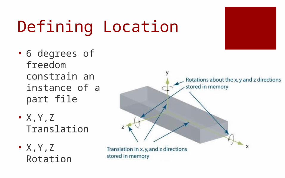
Defining Location
• 6 degrees of freedom constrain an instance of a part file
• X,Y,Z Translation
• X,Y,Z Rotation

Assembly Constraints(position two components relative to one another)
• Coincident
• Parallel
• Perpendicular
• Tangent
• Concentric
• Lock
• Distance
• AngleThe bridge example will be used to demonstrate
these core concepts

Concentric Constraints
Axes of cylindrical features and holes can be selected
Concentric constraints align centerline axes

Mating Surfaces
2D surfaces can be mated using the Coincident Constraint to become
flush with one another but the correct direction must be given to
the computer

Additional Constraints
Distance between entities if not flush
Coincident Lines or Vertices
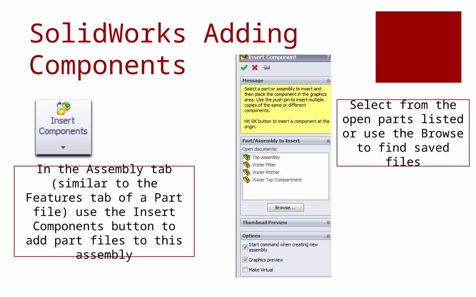
SolidWorks Adding Components
In the Assembly tab (similar to the Features tab of a Part
file) use the Insert Components button to add part files to this assembly
Select from the open parts listed or use the Browse to
find saved files

After placing the base part, reopen the Insert Component dialog box and click on the pin to keep the box open. Now browse and double click on or Open the second part and left SINGLE click in SolidWorks window to place second part. Next go to the Insert Component dialog box and single left click on the second part just inserted so that it’s blue high-lighting is removed. Now click on browse and select the third part, left SINGLE click to place it, left click on the third part in the Insert Component dialog box to remove the blue high-lighting and repeat sequence. After placing the last part, select the green check mark or hit ESC to complete the insertion of parts. Note that if multiple copies of any part are needed, one can SINGLE click again after the part has been placed to produce another copy of the part.
SolidWorks: First Component
The first part inserted will become fixed in space and should be placed at the origin as a base for the assembly. This must be done by selecting the part and then clicking the green check mark to default to the origin instead of just left clicking in space.
ANCHORING THE BASE AT THE ORIGIN
INSERTING ADDITIONAL PARTS

SolidWorks Constraints/Mates
In SolidWorks these are the Standard Constraints
used in Assemblies
In the figure window it will show a preview of the mating and a smaller dialog box
will appear
Change Direction
Confirm Mate

The Secret to Successful Assemblies
1. Move components to be constrained close to each other
2. Rotate one component so the constrained surfaces or edges can be easily viewed
3. Zoom in so that the surface or edges are easy to select
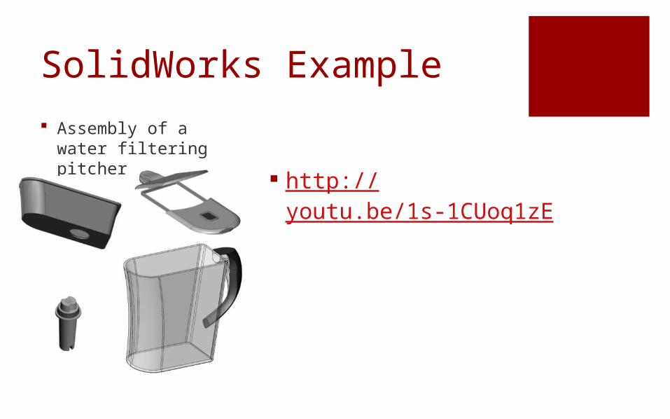
SolidWorks Example Assembly of a water
filtering pitcher
http://youtu.be/1s-1CUoq1zE

Water Pitcher StartThe first part inserted will become fixed in space and will be placed at
the origin aligning the 3 major planes (front, right, top) as a base for the
assembly by selecting the part in the open parts list and clicking the
green check mark
Origin of Assembly
Origin of Base Part Aligned Origins

Water Pitcher Example:First Mate
Next lets bring in the top
compartment and mate the two back
surfaces

Water Pitcher:Top Compartment
Similar constraints are added to the sides and top ridge in order
to fully constrain the top compartment

Water Pitcher: Filter
Now lets add to our assembly the water filter which
fits into the circular hole of the top compartment
We’ll add a concentric
constraint in order to align the axis

Water Pitcher: Inserted Filter
The bottom ridge of the filter and the top of the
compartment are selected and the faces are constrained to be
flush
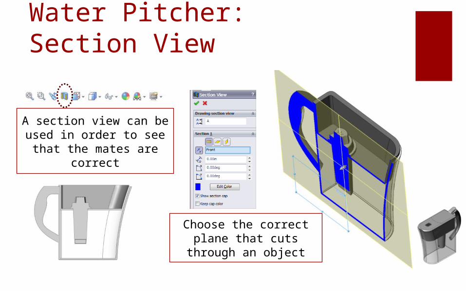
Water Pitcher: Section View
A section view can be used in order to see that
the mates are correct
Choose the correct plane that cuts through
an object

Water Pitcher: Sub-Assembly
The top cover of the water pitcher consists of 2 pieces that were put together in a separate
assembly and then brought into the current
assembly

Deleting Constraints
All Constraints applied are located in the Model Tree under
Mates

Deleting Constraints
Constraints can be selected and removed using the delete key

Assemblies Wrap-Up Assemblies – collection of
3D parts that form a system
6 Degrees of Freedom• XYZ Translation• XYZ Rotation
Assembly Constraints• Concentric• Mating Surfaces• Coincident• Distance
Homework Assignment SW06-OUT :
Buck-Eye-PhoneAssembly
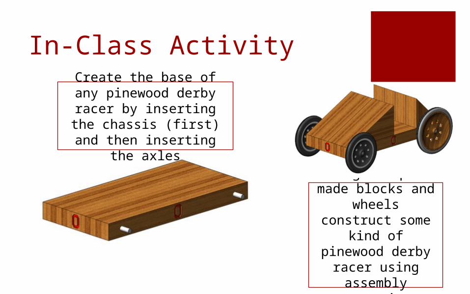
In-Class Activity
Using the pre-made blocks and wheels construct
some kind of pinewood derby
racer using assembly
constraints
Create the base of any pinewood derby racer by
inserting the chassis (first) and then inserting
the axles

Important Takeaways Assemblies are collections of 3D
parts that form one engineering system
Assembly constraints are used to locate parts in the assembly relative to each other

What’s Next?
Due Next Class: SW06 Out of Class HW
Before next class, you will read about Exploded View and Extracting Drawings and Optional Extra Credit Advanced Assembly Modeling