assessing lora for satellite-to-earth communications
TRANSCRIPT

Received July 7, 2020, accepted August 30, 2020, date of publication September 7, 2020, date of current version September 22, 2020.
Digital Object Identifier 10.1109/ACCESS.2020.3022433
Assessing LoRa for Satellite-to-EarthCommunications Considering theImpact of Ionospheric ScintillationLARA FERNANDEZ 1,2,3, (Student Member, IEEE),JOAN ADRIA RUIZ-DE-AZUA 1,2,3, (Member, IEEE),ANNA CALVERAS 2, AND ADRIANO CAMPS 1,3, (Fellow, IEEE)1CommSensLab-UPC, Department of Signal Theory and Communications, UPC BarcelonaTech, 08034 Barcelona, Spain2Department of Network Engineering, UPC BarcelonaTech, 08034 Barcelona, Spain3Institut d’Estudis Espacials de Catalunya (IEEC) - CTE-UPC, 08034 Barcelona, Spain
Corresponding author: Lara Fernandez ([email protected])
This work was supported in part by the Spanish Ministry of Economy and Competitiveness, by the Spanish Ministry of Science, Innovationand Universities, Sensing with Pioneering Opportunistic Techniques, under Grant RTI2018-099008-B-C21, in part by the Unidad deExcelencia Maria de Maeztu under Grant MDM-2016-0600, in part by the European Regional Development Fund (ERDF) and the SpanishGovernment under Project PID2019-106808RA-I00 AEI/FEDER UE, and in part by the Secretaria d’Universitats i Recerca delDepartament d’Empresa i Coneixement de la Generalitat de Catalunya under Grant 2017 SGR 376 and Grant 2017 SGR 219.
ABSTRACT Since the appearance of 5G, Internet of Things (IoT) has gained an increased interest, withmultiple technologies emerging and converging to cover different user needs. One of the biggest challengestoday is to have global IoT coverage, ensuring seamless communication with IoT devices placed in ruraland even remote areas. Satellite constellations, and in particular CubeSats orbiting in Low Earth Orbit, canprovide a solution to these challenges. Out of the technologies available, LoRa (Long Range) has a greatpotential for implementation in space-to-Earth satellite communications. As the space-to-Earth channel isdifferent with respect to the conventional Earth-to-Earth one, it is important to asses the capabilities of LoRain this new environment. This paper presents a study of different LoRa device configurations to identifythe constrains for each one and determine which one is better for particular mission requirements. Also,the effect of ionospheric scintillation is assessed with a SDR-based (Software-Defined Radio) test set-up thatevaluates the performance of this technology against with Humprey’s ionospheric scintillation model. Thisphenomena produces deep signal intensity fadings and phase fluctuations in equatorial regions, and mainlyphase fluctuations in high latitudes. The obtained metrics are the received power and the packet deliveryratio as a function of the intensity scintillation index, and show the robustness of the LoRa modulation inthese new environments.
INDEX TERMS CubeSat, Internet of Things, ionospheric scintillation, LoRa, satellite communications.
I. INTRODUCTIONInternet of Things (IoT) aims at connecting devices(or ‘‘things’’) placed around the globe for environmentalmonitoring, safety purposes, amongst others. One challengeis that the amount of information of these devices must beexchanged around the world. Therefore, the ‘‘things’’ requirethe capability to transmit and receive information, and requireconnectivity to a network such as the Internet or other private
The associate editor coordinating the review of this manuscript and
approving it for publication was Pietro Savazzi .
networks. In some use cases, these devices are located inrural or remote areas, so they are designed to be low-powerto reduce the maintenance interaction. This allows to powerthem with batteries, solar panels or by harvesting energyfrom the environment, achieving up to several years of auton-omy. However, this low-power profile also constrains thetransmitted power to communicate, impacting directly to thecommunications range and data rate.
Considering these premises, several IoT technologies haveemerged covering different needs. Standards such as IEEE802.15.4 [1], Bluetooth Low Energy (BLE) [2] or ZigBee [3]
165570 This work is licensed under a Creative Commons Attribution 4.0 License. For more information, see https://creativecommons.org/licenses/by/4.0/ VOLUME 8, 2020

L. Fernandez et al.: Assessing LoRa for Satellite-to-Earth Communications
define protocol stacks for devices that are low power and idealfor scenarios that require a short communications range, suchas those in urban areas. On the contrary, if these devices aremeant to be placed in rural or remote areas the deployment ofa costly infrastructure would be necessary to connect them toa network.
Longer range IoT technologies have also appeared toease the deployment of these devices in rural areas. Someof them are categorized as Low Power Wide Area Net-works (LPWAN). LPWAN networks cover between 1 km and10 km in urban areas, and between 10 km and 20 km in ruralareas [4]. Each of the devices communicates independentlywith a gateway or base station which is connected to thenetwork, as seen in Fig. 1. The communication is bidirec-tional, defining the uplink as the messages sent from thedevices to the gateway and the downlink as the messagesfrom the gateway to the devices. Having the gateway as thecentral node and the long communications range, reduces theinfrastructure deployment in rural areas, and although thisarchitecture is feasible to deploy in rural areas, in remoteareas, such as the poles or oceans, it proves to be challeng-ing and expensive. Thus, an alternative infrastructure thatprovides coverage to those remote areas is still necessary todeploy.
FIGURE 1. LPWAN technologies network architecture.
A constellation of Low Earth Orbit (LEO) Satellites can bea valid solution for these scenarios, as suggested in [5]. Thisconstellation can provide global coverage, and lower latencyand losses, as compared to Geostationary satellites which donot cover the poles and have more propagation delay andpath losses. Moreover, in recent years a rapid development oftechnologies for small satellites has appeared, specially sincethe emergence of the CubeSat standard [6] which has boostedthe technology development and reduced the launch costs.This standard defines the external envelope of the spacecraft,easing the interface with the launcher and allowing to performa massive production of all the basic avionics included in thespacecrafts.
Taking these premises, a constellation of CubeSats thatembark LPWAN gateways would provide coverage for thoseIoT devices placed in remote areas with a reasonable cost.However, space-to-Earth communications are more challeng-ing than Earth-to-Earth ones, mainly because the channel
losses and the Doppler frequency shifts are higher and -possibly- because of the ionospheric effects.
Losses are modeled with the Free Space Path Losses(FSPL) model, since line-of-sight between the Satellite andthe Ground receiver is achieved. Additionally, the signals canalso be attenuated by effects, such as atmospheric absorp-tion, rain and cloud attenuation, and ionospheric scintillation.This last phenomena can play a critical role at UHF andL-bands [7], since it may produce deep and long intensityfadings and phase shifts, mainly in Polar and Equatorialregions. Moreover, due to the satellite dynamics there is ahighDoppler frequency shift in the signal carrier. For all thesereasons, it is necessary to asses the feasibility of embarkingLPWAN technologies in satellites.
This work aims at presenting a trade-off study of differ-ent LPWAN technologies to be embarked in CubeSat plat-forms. In this trade-off the selected technology is LoRa. Thistechnology has previously flown in two missions, one fromLacuna Space [8] and another one from Fossa Systems [9],and it has also been studied in [10]–[12] assessing differ-ent aspects of the technology if it was embarked in satel-lites. Overall, this work presents 1) a trade-off and analysisbetween the most relevant LPWAN technologies, 2) a linkbudget study to characterize the requirements of the system,and 3) the results of different tests which include the iono-spheric effects.
The article is organized as follows: Section II presents thetrade-off between different LPWAN technologies. Section IIIcompares the link budget for different configurations of theLoRa system. Section IV details the results from the Iono-spheric Scintillation tests. Finally, Section V presents theconclusions.
II. LPWAN TECHNOLOGIES TRADE-OFFThe LPWAN technologies to highlight currently used areSigfox [13], NarrowBand-IoT (NB-IoT) [14], and LoRa [15].To evaluate the different technologies a comparison of thePhysical/Media Access Control (PHY/MAC) layer charac-teristics, such as modulation-coding techniques, frequencyband, among others are considered to be used in LEO space-to-Earth communications.
Sigfox technology intends to connect objects to the digitalworld. This technology employs a Binary Phase Shift Key-ing (BPSK) modulation transmitting in unlicensed Industrial,Scientific, and Medical radio (ISM) bands. In some of thesebands the transmitted power can be up to 22 dBm, anddue to the modulation used the received power sensitivityis −126 dBm. This technology can achieve a data rate from100 up to 600 bps, depending on the area, and it is capa-ble to compensate a frequency drift up to ±30 Hz [16].Also, the MAC layer protocol is tolerant to the delay experi-enced when communicating using LEO satellites. However,the deployment of base stations is entitled solely to Sigfox,so it is not possible for third parties to embark gateways insatellites.
VOLUME 8, 2020 165571

L. Fernandez et al.: Assessing LoRa for Satellite-to-Earth Communications
TABLE 1. Main LPWAN technologies comparison.
NB-IoT, referred to as the cellular LPWAN, has beendeveloped by the 3rd Generation Partnership Project(3GPP) [14] and is integrated as part of the 4G and 5Gnetworks. This technology uses a narrow-band QuadraturePhase-Shift Keying (QPSK) modulation in a licensed band,with a maximum transmitted power of 23 dBm and a sen-sitivity of −125 dBm. The data rate is 26 kbps from thebase station to the devices and 66 kbps from the devicesto the base station, but eventually it can have peaks of upto 250 kbps. The NB-IoT waveforms and PHY/MAC layerprotocol is impacted both by delay and Doppler [17]. Thus,this protocol needs to be adapted if it had to be used in space-to-Earth communications [18]. Moreover, the base stationsare deployed by Mobile Network Operators (MNO).
LoRa is a technology developed by Semtech. It uses aproprietary Chirp Spread Spectrum (CSS) modulation, whichis more resilient than others to interference and jamming,and it transmits in the unlicensed ISM bands. The LoRatechnology has several parameters that must be configuredin the transceivers, such as the transmitted power, Bandwidth(BW), Spreading Factor (SF), and Coding Rate (CR). Thetransmitted power can be up to 22 dBm, and the sensitivitycan be as low as−125 dBm, offering a data rate up to 27 kbps.LoRa can be used with different MAC layer protocol, beingLoRaWAN the most established one. LoRaWAN is opensource and it is optimized for battery powered end-devices.There are several manufacturers that offer both LoRamodulesand Gateways as COTS components. Therefore, it is feasibleto propose a satellite gateway solution based on the LoRatechnology.
Over the past years, LoRa has gained interest for satellitecommunications, assessing the limitations of the technol-ogy and even bringing it to space. For instance, an strato-spheric balloon test [19] with LoRa modules was conductedto determine the maximum distance that could be achieved,reaching 832 km. Also, Lacuna Space [8] plans to launch aconstellation of satellites with LoRa technology to provideglobal coverage. In fact, it has recently launched a CubeSatwith a LoRa Gateway [20]. Also, Fossa Systems [9] haslaunched a PocketQube [21] with a LoRa transceiver, that cancommunicate with their Ground Module [22].
Some research has also been done on the topic. Authorsin [10] analyse the compatibility of LoRaWAN with satel-lite communications, and identify the challenges in termsof MAC layer when deploying a LPWAN satellite back-haul. Also, in [11] the adaptability of the LoRa modulationfor satellite communications is studied. Moreover, Authorsin [12] have demonstrated that the LoRamodulation is able tocompensate the Doppler effect experienced by LEO satellites.However, to authors’ knowledge there is no physical layerstudy assessing the feasibility to use LoRa for LEO-basedcommunications.
Given the compatibility of the LoRa modulation withsatellite communications, and the ease to deploy gateways,as compared to NB-IoT and Sigfox, this is the technologythat will be studied in this work.
III. ANALYSIS OF LINK BUDGETThis section aims at characterizing the LoRa technologyphysical layer in the space-to-Earth communications environ-ment. The objective is to identify the requirements to havelink budget between a CubeSat and a COTS ground device,and at the same time proposing a transceiver architecture forthe spacecraft. The analysis is conducted for modules oper-ating at 868 MHz and 915 MHz, because the 868 MHz bandcan be used over Europe, Russia and India, and the 915 MHzband over the United States of America and Australia.
A. SCENARIOThe link budget assesses the communications link betweena satellite and a static ground terminal. The study considersdifferent configurations for the satellite terminal, obtainingthe expected received power and Signal-to-Noise ratio (SNR)for the uplink and for the downlink. The received power iscompared to the sensitivity for each SF. Moreover, channelcapacity is also taken into consideration, since having alarger capacity implies having more users that can access thenetwork.
To perform the analysis there are some key aspects thathave to be defined 1) the satellite orbit, which determines thedistance between the satellite and the ground terminal; 2) thesatellite and ground terminal configuration; 3) the channelmodel; and 4) the expected noise power.
1) SATELLITE ORBITThe analysis considers that the satellite is orbiting in LEOwith a circular orbit (i.e. eccentricity of 0◦) at an altitude(h) of 550 km. The inclination of the orbital plane is not takeninto consideration, since the distance between the satellite andthe ground device is the same for any inclination.
Considering the orbit defined, a set of link budgets arecomputed according to different distances between the satel-lite and the ground device, which corresponds to differentelevation angles of visibility with respect to the grounddevice. Thus, the maximum link distance would be 1815 kmat an elevation of 10◦ and the minimum would be the orbitalheight 550 km, at an elevation of 90◦.
165572 VOLUME 8, 2020

L. Fernandez et al.: Assessing LoRa for Satellite-to-Earth Communications
FIGURE 2. Satellite configurations.
The maximum Doppler frequency shift depends on thesatellite speed, which is vsat = 7.8 km/s. Being the maxi-mum experienced Doppler:
1f = 22.56 kHz for f0 = 868 MHz and (1)
1f = 23.78 kHz for f0 = 915 MHz. (2)
2) SATELLITE AND GROUND TERMINAL CONFIGURATIONSThe satellite and the ground terminals are considered tohave the same devices: the Semtech SX1261 module [23],for the 868 MHz band, and the SX1262 one [23], for the915 MHz band. As mentioned before, the analysis consid-ers four different satellite configurations. These have beenselected to increase the transmitted power, receiving gainand the directivity of the antenna, to have link budget inthe longer ranges experienced in satellite communications.The first configuration assumes that the satellite embarks aLoRa transceiver with a monopole antenna, (Fig. 2a). Thisconfiguration will be referred as MON.
The second configuration extends the former one witha radiofrequency Front End (RF-FE), which is conformedby a power amplifier (PA) in the transmitting chain, anda low noise amplifier (LNA) and a filter in the receiv-ing chain, (Fig. 2b). The configuration will be referredas MON+RF-FE.
The third configuration consists of the LoRa transceiverwith a directive antenna instead of a monopole, (Fig. 2a).This one will be referred as DIR. Finally, a combination ofthe front end and the directive antenna is done for the fourthconfiguration, (Fig. 2b), which will be called RF-FE+DIR.
The ground terminal is assumed to have the first configu-ration (MON) with the LoRa module and monopole antenna,to simplify it and prevent having to point the antennas towardsthe spacecraft which would be necessary if using a direc-
tive antenna. Thus, the transmission power and modulationparameters are assumed to be the same for the MON config-uration and for the ground terminals.
The transmitted power is configured to 14 dBm at 868MHzand 22 dBm at 915 MHz, these values are the maximum onesaccording to the datasheet of the modules [23]. However, forthe configurations that incorporate the RF-FE, the transmit-ted power is the one given by the PA, 30 dBm [24] and inthe receiving chain the LNA is considered to have a gainof 16 dB [25].
The gain of the antennas is considered to be 0 dB forthe monopole and 10 dB with the directive antenna. Forthis directive antenna the directivity could be achieved forexample, with a 3 element patch antenna array, a 4-5 turnshelix antenna, or a 4-5 elements Yagi-Uda antenna.
In the LoRa modulation the BW is configurable, andaccording to the datasheet [23], this parameter determinesthe maximum shift in the central frequency that the modulesare able to compensate, and the noise power. The shift thatthe modules compensate can be up to 25% of the BW. Thisvalue has to be higher than the Doppler effect, in order tobe naturally compensated by the module itself. However,this confronts with the relationship between the bandwidthand the noise power. Specifically, the bandwidth should bethe smallest value possible to reduce the noise power andtransmission time. Considering that the typical values are125 kHz, 250 kHz and 500 kHz, and taking into considera-tion the two constrains mentioned above the optimum BWwould be 125 kHz, since it can compensate up to±31.25 kHzof frequency shift.
The CR is also configurable, and can be set to 4/5, 4/6,4/7 or 4/8, having 1, 2, 3 or 4 bytes of redundancy respec-tively, it should be noted that the CR is defined as the numberof information bits divided by the total number of bits sent.This CR provides a code gain that for the LoRa modulation is
TABLE 2. Summary of satellite configurations.
VOLUME 8, 2020 165573

L. Fernandez et al.: Assessing LoRa for Satellite-to-Earth Communications
not specified, in fact, the sensitivity depends only on the SFand the BW. So, in the link budget no coding rate gain isconsidered, being a worst case scenario (i.e. conservativestudy).
All these modulation parameters determine thecapacity (C) in bps of the channel, which is computed asshown in 3, where C is the capacity of the channel in bps,BW is the Bandwidth in Hz, SF is the selected SF and CR theused coding rate.
C = SFCR[2SFBW
] (3)
As a consequence, the capacity increases with an increaseof the BW and with a decrease of the SF. Also, the higherthe redundancy the less C in the channel. For this reason,since the CR is not considered for the link budget, the bestcase in terms of capacity will be assumed, which cor-responds to a CR of 4
5 , having the lowest redundancypossible.
Finally, a safety margin of 3 dB is added to the receivedpower. This margin is included to compensate extra lossesthatmay not be considered such as the accuracy of transmittedpower of the transceivers, which according to the datasheetis ±2 dB [23].
3) CHANNELThe channel in space-to-Earth communications experiencesfree-space path losses (FSPL). These FSPL in dB can becalculated as a function of the frequency (f) in Hertz and thedistance (d) in meters between the satellite and the groundterminal, as shown in (4).
FSPL = 20log(d)+ 20log(f )− 147.55 (4)
Aside from the losses introduced by FSPL, 3 dB of atmo-spheric losses, and 3 dB of polarization losses are also con-sidered, which is the maximum for a link between a linearpolarized antenna and a circular one. Moreover, 3 dB ofpointing losses are taken into account for the configurationsthat include a directive antenna, but are considered negligible(i.e. 0 dB) when using a monopole.
4) NOISE POWERTo calculate the noise power, first the noise temperature hasto be defined. The systems noise temperature is different foruplink, ground terminal to satellite, and downlink, satelliteto ground terminal. In the uplink 290K are considered as aworst case [26], so this antenna temperature will be used forthe analysis.
For the downlink the antenna temperature can be calculatedas
TA = TSKY + TGROUND, (5)
where the TGROUND can be estimated as 2320K for a medianbusiness area, whilst the TSKY can be estimated as 20K. Thus,TA equals to 2340K .
Considering the noise temperatures, the expected noisepower is:
Nuplink = −108 dBm and (6)
Ndownlink = −114 dBm. (7)
B. LINK BUDGET RESULTSThe results for the link budget analysis are presented in thissection, both for the 868 MHz modules and the 915 MHzones.
1) LINK BUDGET AT 868 MHzThe results for the 868 MHz uplink and downlink are shownin Figs. 3 and 4, respectively. These plots represent thereceived power, Pr , and the Signal to Noise Ratio (SNR) asa function of the elevation of the satellite. The sensitivity,Ps, for each of the SFs is also represented, to asses for whichvalues of SF is possible to have communication with thedifferent configurations.
FIGURE 3. Uplink received power Pr and SNR for 868 MHz transceiver.
FIGURE 4. Downlink received power Pr and SNR for 868 MHz transceiver.
165574 VOLUME 8, 2020

L. Fernandez et al.: Assessing LoRa for Satellite-to-Earth Communications
For the MON configuration (the red line in the plots)the communication cannot be established in any elevation.Therefore, this configuration is not suitable for space-to-Earth communications. In fact it is required to extend thisarchitecture with other components.
If, instead the DIR configuration is considered, whichcorresponds to the blue line in the plots, the communicationis possible from 33◦ of elevation with an SF of 12 andfrom 48◦ with an SF of 11, both for the uplink and thedownlink. Although with a directive antenna is possible tohave communication, placing this antenna in a satellite ismore challenging than placing a monopole. Mainly becausethese antennas require pointing the spacecraft towards thesurface of the Earth, so it is necessary to have precise attitudedetermination and control.
An alternative to directive antennas is to have the LoRatransceiver with an RF-FE and a monopole antenna, whichcorresponds to the MON+RF-FE configuration. This config-uration, represented as a green line, is also better in terms oflink budget with respect to the other two already presented,and it does not require precise attitude pointing. In the down-link it achieves communication for any elevation with an SFof 11 and from an elevation of 45◦ with an SF of 8, and in theuplink for any elevation with an SF of 12 and from 52◦ withan SF of 9.
Finally, the DIR+RF-FE configuration, shown as a pinkline, is able to achieve communication in the downlink withan SF of 8 for any elevation, and with an SF of 7 for eleva-tions above 19◦. In the case of the uplink, communication isfeasible for any elevation for an SF of 9, and with an SF of 7from 32◦. Even though this configuration faces the challengesof including the directive antenna, it is the one that providesmore channel capacity since an SF of 7 can be used.
A summary with the minimum required elevation for eachof the SF and configurations is shown in Table. 3. As aconclusion, having the MON configuration communicationis not viable. A solution to improve the link budget couldbe either DIR or the MON+RF-FE configurations. Betweenthese two solutions, theMON+RF-FE has more performanceand is also less demanding in terms of attitude pointing.
TABLE 3. Minimum elevation to have communication in the uplink andthe downlink for 868 MHz.
Finally, the DIR+RF-FE configuration could be an option forapplications that require having a higher capacity or applica-tions with a high density of users.
2) LINK BUDGET AT 915 MHzThe link budget with the 915 MHz presents larger receivedpower than in the 868 MHz case, since the transmitted poweris higher, as explained in Section III-A2. The results for thisconfiguration can be seen in Figs. 5 and 6.
FIGURE 5. Uplink received power Pr and SNR for 915 MHz transceiver.
FIGURE 6. Downlink received power Pr and SNR for 915 MHz transceiver.
In this case the communications with the MON configura-tion is possible from an elevation of 42◦ at an SF of 12 andabove 62◦ for an SF of 11. However, if the DIR one isused, communication is possible for any elevation with an SFof 11 and from 60◦ of elevation communication is feasiblewith an SF of 8.
The MON+RF-FE configuration has a similar receivedpower in the downlink than the DIR configuration. However,for the uplink it can achieve communication at higher SFs,
VOLUME 8, 2020 165575

L. Fernandez et al.: Assessing LoRa for Satellite-to-Earth Communications
having link budget for any elevation with an SF of 10 andfrom 42◦ with an SF of 7.
Finally, for the DIR+RF-FE communication is possible forany elevation at a SF of 7 for the uplink and from 17◦ for thedownlink.
Table. 4 summarizes the minimum elevations required tohave communication with the different configurations. Over-all with the 915 MHz modules there is more margin in thelink budget as compared to the 868 MHz ones, since thetransmitted power is 8 dB higher. Thus, even with the MONconfiguration the communication is feasible, but only at highelevations and with low data rate. If more channel bandwidthis needed using either the DIR or MON+RF-FE configu-rations is an option. However, since the MON+RF-FE hashigher received power and it does not require to have accuratepointing of the satellite, this option is preferred. Finally,having the configuration with both the RF-FE and a directiveantenna allows using the maximum channel capacity that theLoRa modulation can provide with the fixed bandwidth.
TABLE 4. Minimum elevation to have communication in the uplink andthe downlink for 915 MHz.
IV. ANALYSIS OF IONOSPHERIC SCINTILLATION EFFECTSThis section presents the impact of the ionosphere scintilla-tion in the propagation. This phenomena cannot be evaluatedas part of the link budget, since it produces rapid fadings withvariable durations. For that reason, a set of tests is performedto asses the impact that ionosphere scintillation has on theLoRa modulation.
A. THEORETICAL BACKGROUNDIonospheric scintillation are rapid intensity and phase fluc-tuations induced in the radio-signals as they pass throughthe ionosphere. This phenomena is produced by the spatialinhomogeneities in the electron density in the ionosphere thatproduce a focusing/defocusing of the electromagnetic waves.
The parameter that models the effect of ionosphere inten-sity scintillation is the S4 index which, as seen in 8, is cal-culated from the intensity of the signal (I ). Regarding thephase, it is characterized by σφ . However, the implementedmodel for the tests, is the Humprey’s model [27], that usestwo parameters S4 and τ0, which is related to the fading
FIGURE 7. LoRa signal processing modelling.
FIGURE 8. LoRa signal reproduction using GNU Radio and log file storing.
duration. The S4 and τ0 can be related to an S4 and σφ pair.
S4 =
√〈I2〉 − 〈I 〉2
〈I 〉2(8)
The typical values of S4 index range from 0.1 to 1, valuesbelow 0.3 are considered as low ionospheric scintillation,from 0.3 up to 0.6 it is medium, and from 0.7 upwards it issevere scintillation. These tests are performed for S4 between0.1 and 0.9. τ0 is set to 0.4 s, which is a typical averagevalue [27].
B. TEST SETUPThese tests are performed with the 915 MHz modules usingthe same bandwidth as in the link budget of 125 kHz witha SF of 7, since it is the option that provides a higher channelcapacity. Moreover, the study is performed for two differ-ent CRs, 4
5 and 46 , to asses the impact of having redundancy.
Taking into account these modulation parameters, commu-nication is only possible for the RF-FE and Directive antennaconfiguration of the link budget. Out of this configurationthe best and worse cases in terms of received power will betested. The best case corresponds to the uplink with a receivedpower of −110 dBm and the worst case is achieved in thedownlink and corresponds to the sensitivity for this SF whichis −123 dBm.
165576 VOLUME 8, 2020

L. Fernandez et al.: Assessing LoRa for Satellite-to-Earth Communications
To perform the tests, a LoRa signal was recorded usingan Ettus Universal Software Radio Peripheral (USRP)B200 mini. This recording contains LoRa packets which aresent periodically, with a periodicity higher than the transmis-sion and processing time of the modules, ensuring that nopackets are lost due to unavailability of the receiver. Also,the packets for both CR configurations have the same Payloadlength, which implies that adding redundancy enlarges thesize of the packets.
One recording is done for each of the CR configura-tions and a total of 500M samples at a sampling frequencyof 1 Msps are recorded for each one. The number of sam-ples is constrained by the amount of data generated by therecordings and the post processing. It should be noted thatnumber of samples of the recording, determines the totalnumber of packets recorded, which are 68 packets for the CRof 4
5 configuration and 55 packets for the CR of 46 .
These recorded signals are then processed by introduc-ing Humprey’s ionospheric scintillation model [27], [28] tosimulate the propagation channel. The processing is doneby multiplying the phase and quadrature components of therecorded LoRa signal with a realization of the channel model.This process is repeated 50 times and it is saved in a file foreach of the S4 indexes and for each of the CRs. This processis ilustrated in Fig. 7.
Overall, the resulting processed recordings contain3300 packets for the CR of 4
5 case, which correspondsto 50 realizations of the channel with 68 packets each,and 2850 packets for the CR of 4
6 case, so 50 realizationsof 55 packets each. Each of these files are reproduced twice,so that the results obtained are statistically representative.
The processed recordings are then reproduced, usingGNURadio and the Ettus USRP B200 mini. Then, the sig-nal is attenuated, so that the received power corresponds tothe best and worst cases of the link budget, explained inSection III. Finally, the signal is received by a LoRa module.
This module stores the packets received with the receivedpower in a log file for post-processing as seen in Fig. 8. Thepackets stored in the log files are those that have been cor-rectly received after demodulation, which means that packetsthat contain errors are discarded.
It should be noted that the metrics obtained refer toreceived power instead of the Received Signal Strength Indi-catior (RSSI), because spread spectrum modulations can bereceived below the noise level. This implies that when thereceived signal is below the noise level the RSSI measuredcorresponds to the noise power and the SNR is negative.These two metrics are sensed by the LoRa modules. There-fore, the received power in dBm is computed using the RSSIin dBm and the SNR in dB, as follows:
Pr = RSSI if SNR ≥ 0 (9)
Pr = RSSI + SNR if SNR < 0 (10)
From the log files two different metrics are obtained: thePacket Delivery Ratio (PDR) for each of the blocks, whichcorresponds to the number of received packets with respectto the number of transmitted packets. This PDR is plottedusing a statistical boxplot representation, as in [29]. Also,the number of packets received with a certain received poweris plotted for different S4 values. Finally, the throughputachieved for each of the cases is compared. This throughputis calculated as the division of the payload data contained inall the packets received correctly over the span of the totaltime.
C. RESULTSThe results for the best case configuration for a CR of 4
5 areshown in Figs. 9a and 9b. With this configuration the PDR is100 % for the four lowest values of scintillation index (i.e. S4from 0.1 to 0.4). This indicates that all the transmitted packetshave been received and processed correctly. For higher values
FIGURE 9. Measured results with experimental set-up for the best case with CR =45 .
VOLUME 8, 2020 165577

L. Fernandez et al.: Assessing LoRa for Satellite-to-Earth Communications
FIGURE 10. Measured results with experimental set-up for the worst case with CR =45 .
of S4 it decreases up to a 92 %. Given that this configurationhas margin with respect to the sensitivity of the modules,most of the packets affected by fadings are still received andonly those that are affected by multiple deep fadings are notreceived.
Regarding the mean received power, it has a trend todecrease as S4 increases, which is caused by the fadingsintroduced by ionospheric scintillation. The variance ofthe received power increases with the scintillation index.As severity increases more fadings occur with differentamplitudes, leading to different possible values of receivedpower.
Having the same CR, but with the worst condition ofreceived power, the PDR has the same tendency: it decreasesas the severity increases, as seen in Fig. 10a. Although, due
to the link conditions in this case the PDR is has a meanof 57% for the lowest scintillation decreasing up to 36 % forthe severest S4.
The received power for the worst case for a CR of 45 is
shown in Fig. 10b. In this case the mean received power ishigher as severity increases. This is because the packets thatare affected by fadings are lost, whilst those that either do notsuffer fadings or are affected by the small gains that the chan-nel can introduce are still received. Also, the variance in thereceived power is larger, as with the previous configuration.
For a CR of 46 and in the best case, it can be seen in Fig. 11a,
that the trend of PDR is the same as in the previous twocases, where the PDR decreases as iopnospheric scintillationseverity increases. Also, comparing this case with the bestcase for a CR of 4
5 , some packets are not received even for
FIGURE 11. Measured results with experimental set-up for the best case with CR =46 .
165578 VOLUME 8, 2020
L. Fernandez et al.: Assessing LoRa for Satellite-to-Earth Communications
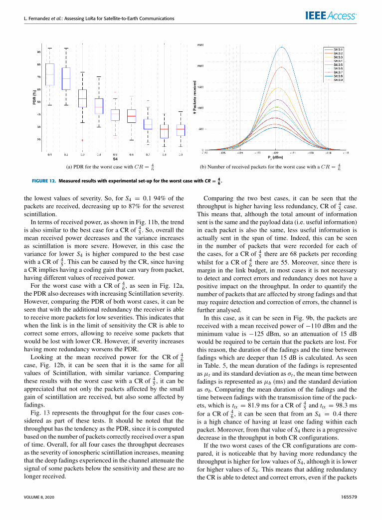
FIGURE 12. Measured results with experimental set-up for the worst case with CR =46 .
the lowest values of severity. So, for S4 = 0.1 94% of thepackets are received, decreasing up to 87% for the severestscintillation.
In terms of received power, as shown in Fig. 11b, the trendis also similar to the best case for a CR of 4
5 . So, overall themean received power decreases and the variance increasesas scintillation is more severe. However, in this case thevariance for lower S4 is higher compared to the best casewith a CR of 4
5 . This can be caused by the CR, since havinga CR implies having a coding gain that can vary from packet,having different values of received power.
For the worst case with a CR of 46 , as seen in Fig. 12a,
the PDR also decreases with increasing Scintillation severity.However, comparing the PDR of both worst cases, it can beseen that with the additional redundancy the receiver is ableto receive more packets for low severities. This indicates thatwhen the link is in the limit of sensitivity the CR is able tocorrect some errors, allowing to receive some packets thatwould be lost with lower CR. However, if severity increaseshaving more redundancy worsens the PDR.
Looking at the mean received power for the CR of 46
case, Fig. 12b, it can be seen that it is the same for allvalues of Scintillation, with similar variance. Comparingthese results with the worst case with a CR of 4
5 , it can beappreciated that not only the packets affected by the smallgain of scintillation are received, but also some affected byfadings.
Fig. 13 represents the throughput for the four cases con-sidered as part of these tests. It should be noted that thethroughput has the tendency as the PDR, since it is computedbased on the number of packets correctly received over a spanof time. Overall, for all four cases the throughput decreasesas the severity of ionospheric scintillation increases, meaningthat the deep fadings experienced in the channel attenuate thesignal of some packets below the sensitivity and these are nolonger received.
Comparing the two best cases, it can be seen that thethroughput is higher having less redundancy, CR of 4
5 case.This means that, although the total amount of informationsent is the same and the payload data (i.e. useful information)in each packet is also the same, less useful information isactually sent in the span of time. Indeed, this can be seenin the number of packets that were recorded for each ofthe cases, for a CR of 4
5 there are 68 packets per recordingwhilst for a CR of 4
6 there are 55. Moreover, since there ismargin in the link budget, in most cases it is not necessaryto detect and correct errors and redundancy does not have apositive impact on the throughput. In order to quantify thenumber of packets that are affected by strong fadings and thatmay require detection and correction of errors, the channel isfurther analysed.
In this case, as it can be seen in Fig. 9b, the packets arereceived with a mean received power of −110 dBm and theminimum value is −125 dBm, so an attenuation of 15 dBwould be required to be certain that the packets are lost. Forthis reason, the duration of the fadings and the time betweenfadings which are deeper than 15 dB is calculated. As seenin Table. 5, the mean duration of the fadings is representedas µt and its standard deviation as σt , the mean time betweenfadings is represented as µb (ms) and the standard deviationas σb. Comparing the mean duration of the fadings and thetime between fadings with the transmission time of the pack-ets, which is ttx = 81.9 ms for a CR of 4
5 and ttx = 98.3 msfor a CR of 4
6 , it can be seen that from an S4 = 0.4 thereis a high chance of having at least one fading within eachpacket. Moreover, from that value of S4 there is a progressivedecrease in the throughput in both CR configurations.
If the two worst cases of the CR configurations are com-pared, it is noticeable that by having more redundancy thethroughput is higher for low values of S4, although it is lowerfor higher values of S4. This means that adding redundancythe CR is able to detect and correct errors, even if the packets
VOLUME 8, 2020 165579

L. Fernandez et al.: Assessing LoRa for Satellite-to-Earth Communications
FIGURE 13. Throughput comparison for the worst cases of link budget.
TABLE 5. Duration and time between fadings below 15 dB forthe S4 cases.
are affected by fadings. However, there is one point for moresevere scintillation where the CR is no longer able to correctthe errors within a packet. To have a better understanding onhow the fadings are affecting the packets, it is also necessaryto analyse the duration and frequency of these. In this case theattenuation necessary to not receive the packets is 4 dB, sincethe mean received power is −122 dBm and the minimum is−126 dBm, as seen on Fig. 12b. Thus, the fadings that havean attenuation lower than 4 dB will be considered.
The duration and time between fadings below 4 dB can beseen in Table. 6. Overall, the mean duration of the fadingsand the time between fadings decreases with an increase inseverity, although these are shorter. If the transmission timeof the packets, which is ttx = 81.9 ms for a CR of 4
5 andttx = 98.3 ms for a CR of 4
6 , is compared with the fadings,it can be seen that for both configurations of CR in meanonly one fading affects the packets up to an S4 = 0.4 andfor higher values in mean two or more fadings can affect thepackets. If the throughput is correlated with the number offadings, in the situation where in mean there is one fading perpacket (i.e. S4 up to 0.4), having more redundancy provides
TABLE 6. Duration and time between fadings below 4 dB for the S4 cases.
more throughput, because for a CR of 46 more errors can be
detected and corrected. Contrarily, for higher values of S4 thepackets contain too many errors, and the CR is no longer ableto correct them. In fact, in this more severe scenario having ahigher transmission time implies having a higher probabilityof being affected by fadings.
V. CONCLUSION AND FUTURE WORKThis study has evaluated the limitations of the LoRa technol-ogywhen using it in space-to-Earth satellite communications.This is first done by means of a theoretical analysis, wherethe link budget is calculated considering the channel modelin space-to-Earth communications. Then, a set of tests areperformed to assess the robustness of the LoRa modulationwhen it is affected by ionospheric scintillation.
As part of the link budget study, four different configura-tions in terms of front end and antenna for the satellite arecompared. The cases are: (1) having the LoRa module and amonopole antenna, (2) having the LoRa module and a direc-tive antenna, (3) having a LoRamodule with a radiofrequencyfront-end and a monopole antenna, and (4) having a LoRamodule with the radiofrequency front-end and a directiveantenna.
The analysis has been conducted for the 868 MHz andfor the 915 MHz modules with a BW of 125 kHz, so thatthe modulation is able to compensate the maximum Dopplerfrequency shifts. The coding gain that the CR provides is notconsidered, since there is no open information on the gainthat it provides. This analysis compares the received powerand SNR as a function of elevation with the sensitivity powerfor each of the SFs. This is done both for the uplink and thedownlink.
The results show that just having the MON configurationcommunication is not possible throughout the whole orbit forany spreading factor for the 868 MHz modules, and it is onlypossible for high elevations, and an SF of 12 for the 915MHzone. Thus, adding a RF-FE or a directive antenna is required.
Between having the DIR and the MON+RF-FE it is iden-tified that the received power is better when incorporating theRF-FE. Moreover, this solution is also less demanding withthe platform, since it does not require attitude pointing.
165580 VOLUME 8, 2020

L. Fernandez et al.: Assessing LoRa for Satellite-to-Earth Communications
Finally, the best case is achieved having theDIR+RF-FE configuration, in which communication isachieved for all SFs and for any elevation with the 915 MHzmodules. In the case of the 868 MHz modules communi-cation is not possible for elevations lower than 30◦. Thislast configuration is the one that can provide more channelcapacity.
The scintillation tests are performed considering the sameBWof 125 kHz, and an SF of 7. The cases studied are the bestand worse of the link budget for these modulation parameters.Moreover, two different coding rates are used, CR = 4
5 andCR = 4
6 , to asses if having more redundancy increases thethroughput. These tests analyze the PDR and the tendencyof the received power for different S4, obtaining also thethroughput.
The results of the tests show that overall the throughputdecreases as ionospheric scintillation severity increases. Forthe two best cases, the throughput is lower for the CR = 4
6case, because there is more redundancy and less payload datacan be sent in the same amount of time. In this case, havingmore redundancy does not have a positive impact since thereis margin in the link budget and not many errors can bedetected and corrected.
Comparing the two worse cases, it can be seen that for lowvalues of S4 having a higher redundancy provides a higherthroughput, since the CR is able to correct some of the errorsinduced in the packets due to the fadings. Although, for moresevere scintillation the behaviour is the opposite, since theCR is no longer able to correct these errors, and havinglarger packets increases the probability of being affectedby fadings. Thus, adding more redundancy is only positivein a scenario where the communications are in the limitof the link budget and the scintillation has low or mediumseverity.
This study has presented the performance of the LoRatechnology in satellite-to-ground communications. Never-theless, this kind of technology enables to establish linkswith large ranges, paying for a low data rate. Its applicationin satellite-to-satellite communications may be investigatedin future researches, which could promote the creation ofsatellite networks, such as the ones presented in Internet ofSatellites (IoSat) paradigm [30].
Finally, this research was possible thanks to the FI-2019grant from AGAUR-Generalitat de Catalunya.
REFERENCES[1] IEEE Standard for Low-Rate Wireless Networks, IEEE Stan-
dard 802.15.4-2015. Accessed: Nov. 2019. [Online]. Available: https://standards.ieee.org/standard/802_15_4-2015.html
[2] Bluetooth. Core Specifications. Accessed: Mar. 2020. [Online].Available: https://www.bluetooth.com/specifications/bluetooth-core-specification/
[3] Zigbee Alliance. Zigbee. Accessed: Mar. 2020. [Online]. Available:https://zigbeealliance.org/solution/zigbee/
[4] K. Mekki, E. Bajic, F. Chaxel, and F. Meyer, ‘‘A comparativestudy of LPWAN technologies for large-scale IoT deployment,’’ ICTExpress, vol. 5, no. 1, pp. 1–7, Mar. 2019. [Online]. Available:http://www.sciencedirect.com/science/article/pii/S2405959517302953
[5] Z. Qu, G. Zhang, H. Cao, and J. Xie, ‘‘LEO satellite constellation forInternet of Things,’’ IEEE Access, vol. 5, pp. 18391–18401, 2017.
[6] CubeSat. Cubesat. Accessed: Nov. 2019. [Online]. Available: http://www.cubesat.org/
[7] J. Aarons, ‘‘Global morphology of ionospheric scintillations,’’ Proc. IEEE,vol. 70, no. 4, pp. 360–378, 1982.
[8] Lacuna Space. Lacuna. Accessed: Nov. 2019. [Online]. Available:https://www.lacuna.space/
[9] FOSSA Systems. Fossa. Accessed: Nov. 2019. [Online]. Available:https://fossa.systems/es/home-spanish/
[10] M. R. Palattella and N. Accettura, ‘‘Enabling Internet of everything every-where: LPWAN with satellite backhaul,’’ in Proc. Global Inf. Infrastruct.Netw. Symp. (GIIS), Oct. 2018, pp. 1–5.
[11] T. Wu, D. Qu, and G. Zhang, ‘‘Research on LoRa adaptability in the LEOsatellites Internet of Things,’’ in Proc. 15th Int. Wireless Commun. MobileComput. Conf. (IWCMC), Jun. 2019, pp. 131–135.
[12] A. A. Doroshkin, A. M. Zadorozhny, O. N. Kus, V. Y. Prokopyev, andY. M. Prokopyev, ‘‘Experimental study of LoRa modulation immunity toDoppler effect in CubeSat radio communications,’’ IEEE Access, vol. 7,pp. 75721–75731, 2019.
[13] Sigfox. Sigfox: The Global Communicator Service Provider. Accessed:Nov. 2019. [Online]. Available: https://www.sigfox.com/en
[14] 3GPP. Release 13. Accessed: Nov. 2019. [Online]. Available:https://www.3gpp.org/release-13
[15] LoRa Alliance. LoRa Alliance. Accessed: Nov. 2019. [Online]. Available:https://lora-alliance.org/
[16] Sigfox. Sigfox Device Radio Specifications. Accessed: Jun. 2020. [Online].Available: https://build.sigfox.com/sigfox-device-radio-specifications
[17] A. Guidotti, A. Vanelli-Coralli, M. Caus, J. Bas, G. Colavolpe, T. Foggi,S. Cioni, A. Modenini, and D. Tarchi, ‘‘Satellite-enabled LTE systems inLEO constellations,’’ in Proc. IEEE Int. Conf. Commun. Workshops (ICCWorkshops), May 2017, pp. 876–881.
[18] Satelliteprome. Sateliot to Invest USD 5.1m in R&D forNanosat Constellation. Accessed: Jun. 2020. [Online]. Available:https://satelliteprome.com/news/sateliot-to-invest-usd-5-1m-in-rd-for-nanosat-constellation/
[19] The Things Network. Lora World Record Broken: 832km/517miUsing 25 mw. Accessed: Nov. 2019. [Online]. Available: https://www.thethingsnetwork.org/article/lorawan-world-record-broken-twice-in-single-experiment-1
[20] Lacuna Space. Lacuna Space AchievesMajorMilestone for LoRa in Space.Accessed: Jun. 2020. [Online]. Available: https://lacuna.space/lacuna-space-achieves-major-milestone-for-lora-in-space/
[21] Dataverse.Pocketqube Standard. Accessed: Jun. 2020. [Online]. Available:https://dataverse.nl/api/access/datafile/11680
[22] Fossa Systems. LoRa Ground Station Development Kit. Accessed:Mar. 2020. [Online]. Available: https://fossa.systems/product/lora-ground-station-development-kit/
[23] SX1261/2 Data Sheet DS.SX1261-2.W.APP, Semtech, Camarillo, CA,USA, 11, rev. 1.1.
[24] Qorvo. RF5110G. Accessed: Jun. 2020. [Online]. Available:https://www.qorvo.com/products/p/RF5110G
[25] Skyworks. Sky67150-396lf: 300 to 2200 MHz Ultra Low-Noise Amplifier.Accessed: Jun. 2020. [Online]. Available: https://www.skyworksinc.com/-/media/SkyWorks/Documents/Products/1901-2000/SKY67150_396LF_202922I.pdf
[26] E. G. Njoku and E. K. Smith, ‘‘Microwave antenna temperature of theEarth from geostationary orbit,’’ Radio Sci., vol. 20, no. 3, pp. 591–599,May 1985.
[27] T. E. Humphreys, M. L. Psiaki, and P. M. Kintner, ‘‘Modeling theeffects of ionospheric scintillation on GPS carrier phase tracking,’’IEEE Trans. Aerosp. Electron. Syst., vol. 46, no. 4, pp. 1624–1637,Oct. 2010.
[28] A. Camps, J. Barbosa, M. Juan, E. Blanch, D. Altadill, G. Gonzalez,G. Vazquez, J. Riba, and R. Orus, ‘‘Improved modelling ofionospheric disturbances for remote sensing and navigation,’’ inProc. IEEE Int. Geosci. Remote Sens. Symp. (IGARSS), Jul. 2017,pp. 2682–2685.
[29] J. A. Ruiz-De-Azua, A. Camps, and A. C. Auge, ‘‘Benefits of using mobilead-hoc network protocols in federated satellite systems for polar satellitemissions,’’ IEEE Access, vol. 6, pp. 56356–56367, 2018.
[30] J. A. Ruiz-de-Azúa, A. Calveras, and A. Camps, ‘‘Internet of satellites(IoSat): Analysis of network models and routing protocol requirements,’’IEEE Access, vol. 6, pp. 20390–20411, 2018.
VOLUME 8, 2020 165581

L. Fernandez et al.: Assessing LoRa for Satellite-to-Earth Communications
LARA FERNANDEZ (Student Member, IEEE)was born in Barcelona, Spain. She received thedegree and M.Sc. degree in telecommunicationsengineering from the Universitat Politècnica deCatalunya, Barcelona, in 2017 and 2019, respec-tively, where she is currently pursuing the Ph.D.degree. She is also participating in the Fly YourSatellite program from ESA. She is a member ofthe FSSCat Project, which is the winner of theESA Sentinel Small Sat (S3) Challenge of the
Copernicus Masters Competition. Her research interests include the Internetof Things, 5G networks, satellite networks, communication systems, andantenna design.
JOAN ADRIA RUIZ-DE-AZUA (Member, IEEE)was born in Barcelona, Spain. He received thedegree in aerospace engineering from Supaero,Toulouse, France, in 2015, the degree in telecom-munications engineering from the UnversitatPolitècnica de Catalunya, Barcelona, Spain,in 2015, and the M.S. degree in network protocolsfrom Supaero, in 2015. He is currently pursuingthe Ph.D. degree with the Universitat Politècnicade Catalunya, Barcelona, Spain. He was awarded
with the best M.S. thesis on Critical Communications from the OfficialSpanish Telecommunications Chartered Institute, in 2016. He has partic-ipated in different projects of ground segment for Ariane 5 and Ariane6 programs in GTD company, in collaboration CNES and ESA. He iscurrently participating in the Fly Your Satellite program from the ESA. He isa member of the FSSCat project, which is the winner of the ESA SentinelSmall Sat (S3) Challenge of the Copernicus Masters Competition. Hisresearch interests include satellite architectures, satellite networks, cognitivenetworks, the Internet of Things, and embedded software.
ANNA CALVERAS was born in Barcelona, Spain,in 1969. She received the Ph.D. degree in telecom-munications engineering from the UniversitatPolitècnica de Catalunya, Spain, in 2000. She iscurrently an Associate Professor with the Wire-less NetworksGroup (WNG), Computer NetworksDepartment, Universitat Politècnica de Catalunya.She has been involved in several national and inter-national research or technology transfer projects.She has published in international and national
conferences and journals. Her research interests and expertise areas comprisethe design, evaluation and optimization of communication protocols andarchitectures for cellular, wireless multihop networks, ad-hoc networks,wireless sensor networks, the Internet of Things, and application domains,such as smart cities, building automation, and emergency environments.
ADRIANO CAMPS (Fellow, IEEE) was born inBarcelona, Spain, in 1969. He received the degreeand Ph.D. degree in telecommunications engineer-ing from the Universitat Politècnica de Catalunya(UPC), Barcelona, in 1992 and 1996, respectively.From 1991 to 1992, he was with the ENS desTélécommunications de Bretagne, France, with anErasmus Fellowship. Since 1993, he has been withthe Electromagnetics and Photonics EngineeringGroup, Department of Signal Theory and Commu-
nications, UPC, where he was an Assistant Professor and an Associate Pro-fessor, in 1997. Since 2007, he has been a Full Professor with UPC. He haspublished more than 215 journal articles in peer-reviewed journals, and morethan 420 international conference presentations. He holds 12 patents. Hisresearch interests include microwave remote sensing, with special empha-sis in microwave interferometric radiometry by aperture synthesis (ESA’sSMOS mission), passive microwave remote sensing using signals of oppor-tunity (GNSS- Reflectometry), and use of nano-satellites as cost-effectiveplatforms to test innovative concepts for Earth Observation, such as the 3Cat-2, a 6U-class CubeSat mission launched in August 2016 carrying on-boardan innovative GNSS-R payload.
165582 VOLUME 8, 2020