assessment and management of ageing of major nuclear power ... · this means controlling within...
TRANSCRIPT
IAEA-TECDOC-1188
Assessment and management of ageing of major
nuclear power plant components important to safety:
In-containment instrumentation and control cables
Volume I
December 2000

The originating Section of this publication in the IAEA was:
Engineering Safety Section International Atomic Energy Agency
Wagramer Strasse 5 P.O. Box 100
A-1400 Vienna, Austria
ASSESSMENT AND MANAGEMENT OF AGEING OF MAJOR NUCLEAR POWER PLANT
COMPONENTS IMPORTANT TO SAFETY: IN-CONTAINMENT INSTRUMENTATION AND CONTROL CABLES
VOLUME I IAEA, VIENNA, 2000 IAEA-TECDOC-1188
ISSN 1011-4289
© IAEA, 2000
Printed by the IAEA in Austria December 2000
FOREWORD
At present, there are over four hundred operational nuclear power plants (NPPs) in IAEA Member States. Operating experience has shown that ineffective control of the ageing degradation of major NPP components (e.g. caused by unanticipated phenomena and by operating, maintenance, design or manufacturing error) can jeopardize plant safety and also plant life. Ageing in these NPPs must be therefore effectively managed to ensure the availability of design functions throughout the plant service life. From the safety perspective, this means controlling within acceptable limits the ageing degradation and wear-out of plant components important to safety so that adequate safety margins remain, i.e. integrity and functional capability in excess of normal operating requirements.
This publication is one in a series of guidance reports on the assessment and management of ageing of the major NPP components important to safety. The reports are based on experience and practices of NPP operators, regulators, designers, manufacturers, and technical support organizations and a widely accepted Methodology for the Management of Ageing of NPP Components Important to Safety, which was issued by the IAEA in 1992.
The current practices for the assessment of safety margins (fitness-for-service) and the inspection, monitoring and mitigation of ageing degradation of selected components of Canadian deuterium–uranium (CANDU) reactors, boiling water reactors (BWRs), pressurized water reactors (PWRs), including the Soviet designed ‘water moderated and water cooled energy reactors’ (WWERs), are documented in the reports. These practices are intended to help all involved directly and indirectly in ensuring the safe operation of NPPs, and to provide a common technical basis for dialogue between plant operators and regulators when dealing with age related licensing issues. The guidance reports are directed at technical experts and managers from NPPs and from regulatory, plant design, manufacturing and technical support organizations dealing with specific plant components addressed in the reports.
The component addressed in the present report is the in-containment instrumentation and control (I&C) cables. The report presents, in two volumes, results of a Co-ordinated Research Project (CRP) on the Management of Ageing of In-containment I&C Cables. Part I, Volume I presents information on current methods for assessing and managing ageing degradation of I&C cables in real NPP environments prepared by the CRP team. An important complement of this information is user perspectives on the application of these methods which are presented in Part II, Volume I. Volume II contains annexes supporting the guidance of Volume I with more detailed information and examples provided by individual CRP participants. For a quick overview, readers should see Section 8 of Part I, Volume I, which describes a systematic ageing management programme for I&C cables utilizing methods presented in the report; Section 9 of Part I, Volume I, which presents CRP conclusions and recommendations; and Part II providing the application guidance from the user’s perspective.
The contributors to drafting and review of this TECDOC are identified at the end of this publication. Their work is greatly appreciated. In particular, the contribution of S.G. Burnay of the United Kingdom as the CRP chairman and a compiler of this report is acknowledged. The IAEA officer who was the project manager of the CRP and directed the preparation of the report was J. Pachner of the Division of Nuclear Installation Safety.

EDITORIAL NOTE The use of particular designations of countries or territories does not imply any judgement by the publisher, the IAEA, as to the legal status of such countries or territories, of their authorities and institutions or of the delimitation of their boundaries.
The mention of names of specific companies or products (whether or not indicated as registered) does not imply any intention to infringe proprietary rights, nor should it be construed as an endorsement or recommendation on the part of the IAEA.

CONTENTS
PART I: FINAL REPORT OF THE CO-ORDINATED RESEARCH PROJECT ON THE MANAGEMENT OF AGEING OF IN-CONTAINMENT I&C CABLES
1. INTRODUCTION.................................................................................................................. 3
1.1. Objective......................................................................................................................... 3 1.2. Scope .............................................................................................................................. 3 1.3. Background..................................................................................................................... 3
1.3.1. Safety aspects of ageing of I&C cables ................................................................ 3 1.3.2. IAEA programme on safety aspects of NPP ageing ............................................. 4 1.3.3. CRP on management of ageing in-containment I&C cables ................................ 5
1.4. Structure.......................................................................................................................... 6 References to Section 1 .............................................................................................................. 7
2. CABLE CONSTRUCTION AND MATERIALS.................................................................. 9
2.1. Cables in use in nuclear power plants ............................................................................ 9 2.2. Cable components......................................................................................................... 11 2.3. Cable materials used in nuclear power plants............................................................... 11
References to Section 2 ............................................................................................................ 13
3. AGEING MECHANISMS ................................................................................................... 14
3.1. General features of ageing of polymers ........................................................................ 14 3.1.1. Basic conditions for ageing to occur .................................................................. 14 3.1.2. Basic effects of ageing........................................................................................ 14
3.2. Understanding ageing mechanisms .............................................................................. 15 3.2.1. Use of a predominance diagram ......................................................................... 15 3.2.2. Arrhenius diagram .............................................................................................. 16 3.2.3. Plasticized PVC: Competition between HCl elimination and evaporation of
plasticizers........................................................................................................... 18 3.2.4. Semi-crystalline polymers: Ageing through a physical transition ...................... 18 3.2.5. Compatibility of materials: The constitution of the cable .................................. 18
3.3. Identification of the main ageing mechanisms ............................................................. 19 3.3.1. Chemical ageing mechanisms ............................................................................ 19 3.3.2. Physical ageing mechanisms .............................................................................. 20 3.3.3. Practical tools for identification of ageing mechanisms..................................... 20
3.4. An approach to facilitate accelerated ageing studies .................................................... 21 References to Section 3 ............................................................................................................ 22
4. MANAGING AGEING OF CABLES THROUGH ENVIRONMENTAL QUALIFICATION .............................................................................................................. 24
4.1. Existing qualification methods ..................................................................................... 24 4.1.1. Objectives ........................................................................................................... 24 4.1.2. Environmental qualification ............................................................................... 25 4.1.3. Concerns in EQ testing....................................................................................... 25 4.1.4. Accelerated thermal ageing ................................................................................ 26 4.1.5. Accelerated radiation ageing .............................................................................. 27

4.1.6. Other environmental conditions ......................................................................... 28 4.1.7. Influence of combined and sequential environmental conditions ...................... 29 4.1.8. DBE and post-DBE testing................................................................................. 29
4.2. Establishing qualification for installed cables in operational NPPs ............................. 30 4.2.1. Cables with no qualification documentation ...................................................... 30 4.2.2. Cables with undefined qualified life or condition .............................................. 31
4.3. Preserving qualification................................................................................................ 31 4.3.1. Monitoring of actual environmental conditions in the plant .............................. 32 4.3.2. Condition monitoring (CM) ............................................................................... 32 4.3.3. Additional accelerated ageing tests .................................................................... 32 4.3.4. Examples ............................................................................................................ 33
References to Section 4 ............................................................................................................ 33
5. IDENTIFYING CABLES OF CONCERN .......................................................................... 35
5.1. Priorities for supplementary ageing management activities ......................................... 35 5.2. Monitoring of environmental conditions...................................................................... 35
5.2.1. Selection of locations for environmental monitoring in the plant ...................... 37 5.2.2. Temperature monitoring..................................................................................... 37 5.2.3. Radiation monitoring.......................................................................................... 39
5.3. Identification of localized severe environments (hot spots) ......................................... 39 5.3.1. Interviews of plant personnel ............................................................................. 40 5.3.2. Review of operating and maintenance experience ............................................. 40 5.3.3. Review of plant layout........................................................................................ 40 5.3.4. Walkdowns ......................................................................................................... 41 5.3.5. Typical hot spots in various NPP designs .......................................................... 41
5.4. Identification of worst case cables................................................................................ 42 References to Section 5 ............................................................................................................ 44
6. CONDITION MONITORING ............................................................................................. 45
6.1. Conditions indicators.................................................................................................... 45 6.1.1. Electrical parameters .......................................................................................... 45 6.1.2. Visual aspects ..................................................................................................... 46 6.1.3. Chemical properties............................................................................................ 46 6.1.4. Mechanical properties......................................................................................... 46
6.2. Sampling methods ........................................................................................................ 47 6.2.1. Cable deposits..................................................................................................... 47 6.2.2. Real time aged cables ......................................................................................... 47 6.2.3. Microsampling methods ..................................................................................... 47 6.2.4. Precautions during in situ measurements and/or sampling ................................ 48
6.3. Available CM methods................................................................................................. 49 6.3.1. Visual/tactile inspection ..................................................................................... 49 6.3.2. Indenter measurements ....................................................................................... 51 6.3.3. OIT/OITP measurements.................................................................................... 52 6.3.4. Thermo-gravimetry analysis (TGA) ................................................................... 53 6.3.5. Other physico-chemical methods ....................................................................... 54 6.3.6. Elongation measurements................................................................................... 54 6.3.7. Reproducibility of CM measurements................................................................ 56 6.3.8. Recommended CM methods for cable materials................................................ 56

6.4. Correlation between jacket and insulation degradations .............................................. 57 6.5. Correlation of CM with DBE survivability .................................................................. 57
References to Section 6 ............................................................................................................ 59
7. PREDICTIVE MODELLING OF CABLE AGEING.......................................................... 62
7.1. Analytical methods ....................................................................................................... 62 7.1.1. Simple linear model for cable materials ............................................................. 62 7.1.2. Power law extrapolation model .......................................................................... 63 7.1.3. Superposition of time dependent data ................................................................ 63 7.1.4. Superposition of end-point dose data ................................................................. 63
7.2. Material specific models............................................................................................... 64 7.3. Application of predictive modelling to NPP cables ..................................................... 64
7.3.1. Application of modelling to new installations.................................................... 64 7.3.2. Application of modelling to existing NPP.......................................................... 65
References to Section 7 ............................................................................................................ 65
8. AGEING MANAGEMENT PROGRAMME FOR IN-CONTAINMENT I&C CABLES .................................................................................. 66
8.1. The need for cable ageing management programmes................................................... 66 8.2. Key elements of a cable ageing management programme............................................ 68
8.2.1. Understanding cable ageing................................................................................ 68 8.2.2. Co-ordination of cable ageing management programmes .................................. 69 8.2.3. NPP operation..................................................................................................... 69 8.2.4. Cable inspection, monitoring and assessment .................................................... 69 8.2.5. Cable maintenance.............................................................................................. 70
References to Section 8 ............................................................................................................ 70
9. CRP CONCLUSIONS AND RECOMMENDATIONS ...................................................... 71
9.1. Conclusions of the CRP................................................................................................ 71 9.2. Recommendations ........................................................................................................ 71
PART II: USER PERSPECTIVES AND GUIDANCE ON IMPLEMENTATION OF AN AGEING MANAGEMENT PROGRAMME FOR CABLES
1. BACKGROUND.................................................................................................................. 75
2. KEY ATTRIBUTES OF CABLE AMP............................................................................... 75
3. APPLICATION GUIDANCE .............................................................................................. 76
3.1. Focused approach on cables of concern ....................................................................... 76 3.2. Visual inspection and other condition monitoring methods......................................... 77
3.2.1. Visual inspection ................................................................................................ 77 3.2.2. Other CM methods ............................................................................................. 78
3.3. Knowledge of actual plant environments ..................................................................... 79 3.4. Knowledge of cable materials ...................................................................................... 81 3.5. EQ programme balance between conservatism and uncertainties .................................. 81

3.5.1. Areas of uncertainty in EQ testing...................................................................... 82 3.5.2. Using existing EQ tests as part of an AMP ........................................................ 84 3.5.3. Refining EQ testing ............................................................................................ 84
GLOSSARY OF TERMS AND ABBREVIATIONS.............................................................. 86
CONTRIBUTORS TO DRAFTING AND REVIEW.............................................................. 89

Part I
FINAL REPORT OF THE CO-ORDINATED RESEARCH PROJECT ON MANAGEMENT OF
AGEING OF IN-CONTAINMENT I&C CABLES

.

3
1. INTRODUCTION
1.1. OBJECTIVE
The objective of Part I of this report is to present the results of the Co-ordinated Research Project (CRP) on the Management of Ageing of In-containment Instrumentation and Control (I&C) Cables addressing current practices and techniques for assessing and managing ageing degradation of I&C cables in real nuclear power plant (NPP) environments. These practices and techniques have a different degree of maturity and practical application experience. Part I provides a technical basis for developing and implementing a systematic ageing management programme and also for dialogue between NPP operators and regulators when dealing with age related licensing issues. Information presented in Part I will also be of interest to NPP designers, suppliers and technical support organizations. Sections 2–7 cover a number of technical methods for ageing management which are at different stages of maturity. Section 8 describes how these technical methods can be integrated to achieve effective ageing management of I&C cables.
1.2. SCOPE
Part I is aimed specifically at low voltage (<1 kV) cables insulated with cross-linked polyethylene (XLPE), ethylene propylene based materials (EPR/EPDM), ethylene vinyl acetate (EVA), chlorosuphonated polyethylene (CSPE) and poly vinyl chloride (PVC) that are used in instrumentation and control circuits inside containment. However, much of the information is relevant to all low voltage power cables used in NPPs, which utilize similar materials and which have similar degradation mechanisms. The report is restricted to ageing of cables and does not cover connectors, terminations, and cable penetrations. It is recognized that economic considerations are important aspects affecting decisions on the type and timing of ageing management actions and continued plant operation. However, since the present report is written primarily from the safety perspective, it deals only with ageing management, which is a component part of life management that involves the integration of ageing management and economic planning.
1.3. BACKGROUND
1.3.1. Safety aspects of ageing of I&C cables
Cables are vital components of I&C systems in NPPs since they link the system components, such as transducers, with the instrumentation and control equipment used to monitor and control the plant. All equipment important to safety, including I&C cables, therefore needs to be qualified to perform its functions both under normal operating conditions and under a design basis event (DBE) and post-DBE conditions occurring at any time during its service (installed) life. (Environmental qualification of transducers and other I&C cables components, such as cable penetrations and junction boxes is not addressed in this report).
4
In many countries, qualification of important to safety I&C cables is based on compliance with the international standard IEC-780 ([1.1], or with national standards such as IEEE-323 (1983) and IEEE-383 (1974) [1.2], French National Codes RCC-E and RCC-M [1.3], and German Safety Standards KTA 3501-3503 and 3505 [1.4]. These standards detail testing procedures using accelerated ageing of cables aimed at demonstrating their ability to survive a DBE after exposure to normal operating conditions for their planned service life (often 40 years). However, since these standards were written, a better understanding of the degradation behaviour of cable materials has been reached. This has led to the development of improved methods for assessing and mitigating ageing in cables in NPPs that could supplement standard qualification tests. Evaluation of the condition of cables using these methods has become important for verifying that cables are being used within the constraints of their environmental qualification and thus providing greater assurance of the long-term functionality of cables, particularly for cables inside containment. An additional safety concern relates to the life extension of existing NPPs beyond the typical design life of 30-40 years. Current economic pressures on utilities to extend plant service life (a total of 60 years being a quoted target) mean that the I&C cables may have to perform safety functions for a time period significantly greater than their initial design life. Effective ageing assessment and management1 of the I&C cables is therefore required to ensure their functional capability throughout the plant service life, including any extended life. In this connection, it is useful to mention that there are currently no practical in situ electrical tests that can verify functionality of installed aged cables under DBE and post-DBE conditions. Therefore, the management of the ageing of cables requires the evaluation of the material condition of cable insulation, which was the focus of the CRP on ageing management of I&C cables.
1.3.2. IAEA programme on safety aspects of NPP ageing
The IAEA initiated activities on safety aspects of NPP ageing in 1985 to increase awareness of the emerging safety issues relating to physical ageing of plant structures, systems and components (SSCs). In 1989 a systematic project aimed at assisting Member States in understanding ageing of SSCs important to safety and in effective ageing management of these SSCs was started in order to ensure their integrity and functional capability throughout their service life. This project integrates information on the evaluation and management of safety aspects of NPP ageing generated by Member States into a common knowledge base, derives guidance and assists Member States in the application of this guidance. Main results of the project are documented in Refs [1.5–1.15]. They fall into three groups.
Awareness. Following up on the first International Conference on Safety Aspects of Ageing and Maintenance of Nuclear Power Plants [1.5] which was organized by the IAEA in 1987, increased awareness of physical ageing of SSCs and its potential safety impact was achieved by the development and wide dissemination in 1990 of an IAEA-TECDOC on Safety Aspect 1 In the Electric Power Research Institute (EPRI) document entitled Common Ageing Technology (1993), ageing assessment is defined as evaluation of appropriate information for determining the effects of ageing on the current and future ability of SSCs to function within acceptance criteria; and ageing management as the engineering, operations and maintenance actions to control within acceptable limits ageing degradation and wear-out of structures, systems or components.

5
of Nuclear Power Plant Ageing [1.6]. While in the 1980s most people believed that classical maintenance programmes were adequate for dealing with the ageing of nuclear plants, in the 1990s the need for ageing and life management of NPPs became widely recognized. Programmatic guidelines. The following programmatic guidance reports have been developed using the experience of Member States.
Data Collection and Record Keeping for the Management of Nuclear Power Plant Ageing [1.7] provides information on the baseline, operating and maintenance data needed and a system for data collection and record keeping.
Methodology for the Management of Ageing of Nuclear Power Plant Components
Important to Safety [1.8] gives guidance on screening SSCs to make effective use of limited resources and on performing ageing management studies to identify or develop effective ageing management actions for the selected components.
Implementation and Review of Nuclear Power Plant Ageing Management Programmes
[1.9] provides information on the systematic ageing management process and an organizational model for its implementation.
Equipment Qualification in Operational Nuclear Power Plants [1.10] documents current
methods and practices relating to upgrading and preserving equipment qualification in operational NPPs and reviewing the effectiveness of plant equipment qualification.
Guidelines for Ageing Management Assessment Team [1.11] is a reference document
for the implementation of one of the Engineering Safety Review Services and for utility self-assessments; these reviews can be programmatic or problem oriented.
Component specific guidelines. The guidance of Ref. [1.8] has been used to implement Co-ordinated Research Projects (CRPs) on management of ageing of concrete containment buildings and in-containment instrumentation and control cables, and to develop comprehensive technical documents on Assessment and Management of Ageing of Major Nuclear Power Plant Components Important to Safety. The comprehensive reports on steam generators [1.12], concrete containment buildings [1.13], CANDU pressure tubes [1.14], PWR pressure vessels [1.15], and PWR vessel internals [1.16] have been issued and five reports are currently being prepared for additional major components. The focus of the project work has progressively shifted from developing awareness, to preparing programmatic and then component specific guidelines. In future, the focus will be on providing services to assist Member States in the application of the guidelines. A reduced effort will be maintained to facilitate information exchange through the preparation of additional guidelines and the upgrading of existing guidelines.
1.3.3. CRP on management of ageing in-containment I&C cables
The CRP on management of ageing of in-containment I&C cables was initiated at the first Research Co-ordination Meeting (RCM) held in Vienna in December 1993. The general objective of the CRP was to identify the dominant ageing mechanisms and to develop an effective strategy for managing ageing effects caused by these mechanisms. The specific objectives were:
6
(a) to validate predictive cables ageing models accounting for synergistic effects that take place when radiation and thermal ageing occur over the long time period associated with real plant environments, and
(b) to provide practical guidelines and procedures for assessing and managing the ageing of I&C cables in real plant environments.
The initial scope of the CRP was limited to those materials and cable types which were considered to be of widest interest. The programme was therefore limited to low voltage (<1 kV) I&C cables based on cross-linked polyethylene (XLPE), ethylene propylene based materials (EPR/EPDM) and ethylene vinyl acetate (EVA). Because of their similarity in materials and construction, low voltage power cables were also included in the programme. The CRP was implemented in two phases. Results of the Phase I CRP (1993-1995) are presented in Ref. [1.17]. They include a summary of the relevant ageing mechanisms; operating experience for a range of NPP types; an overview of ageing management methods which are currently in use; description of cables sampling and laboratory ageing methods and of monitoring and test methods; the capabilities and the limitations of the various ageing management methods. The objectives of the Phase II CRP were to resolve the uncertainties in the relationship between cable condition monitoring techniques and DBE survivability and improve existing initial qualification procedures, and thus to provide a technical basis for the assessment and management of ageing of in-containment I&C cables based on the concepts developed in Phase I CRP. Most of the CRP effort was aimed at: the identification of cables of concern in order to focus limited ageing management resources on a manageable subset of the total cable inventory in plant; and developing a ‘tool box’ of practical condition monitoring (CM) methods through round-robin tests (to identify the most suitable CM methods and their limitations for different cable materials and applications, and to develop test procedures for these methods). Since CSPE and PVC are used in many cables in existing NPPs, these materials have been included in the scope of Phase II.
1.4. STRUCTURE
Section 2 provides a brief description of cable construction types, their subcomponents and the materials most commonly used for jacket insulations. Section 3 summarizes the ageing mechanisms relevant to I&C cables. Section 4 provides an overview of the environmental qualification (EQ) of cables and its preservation throughout the installed life as the primary means of cable ageing management. This section also provides suggestions for supplementary ageing management actions that could be used with existing EQ. The identification of the limited set of cables of concern from the vast amount of cables installed in NPPs is addressed in Section 5 in order to facilitate effective use of limited resources. Condition monitoring methods available for assessing ageing of in-plant cables, including their capabilities and limitations, are described in Section 6. Predictive modelling of environmental ageing in cables is presented in Section 7. Annexes to the technical sections are provided in Volume II of this report, including more detail and examples of specific methods.

7
Section 8 provides an outline of the key elements required in ageing management programme for I&C cables, utilizing the methods presented in the report. Section 9 presents the conclusions of the CRP and recommends follow-up activities that build on the results of this CRP. Please note that Part II of the report, which follows Section 9, presents perspectives of potential users (i.e. NPP operators and regulators) on the methods and practices for ageing assessment and management for I&C cables (documented in Part I).
REFERENCES TO SECTION 1
[1.1] INTERNATIONAL ELECTROTECHNICAL COMMISSION, Qualification of Electrical Items of the Safety System for Nuclear Power Generating Stations, IEC-780, Geneva (1984).
[1.2] INSTITUTE OF ELECTRICAL & ELECTRONIC ENGINEERS, Qualifying class 1E equipment for nuclear power generating stations, IEEE-323 (1974, 1983); Type test of Class 1E electric cables, field splices, and connections for nuclear power generating stations, IEEE-383, New York, NY (1974).
[1.3] ASSOCIATION FRANCAISE POUR LES REGLES DE CONCEPTION ET DE CONSTRUCTION DES MATERIELS DE CHAUDIERES ELECTRO-NUCLEAIRES (AFCEN), Design and Construction Rules for Electrical Equipment of Nuclear Islands, RCC-E; Design and Construction Rules for Mechanical Equipment of Nuclear Islands, RCC-M, AFCEN, Paris (French Standards).
[1.4] BUNDESAMT FÜR STRAHLENSCHUTZ, Kerntechnischer Ausschuss, KTA 3501, Design Features for the Reactor Protection System; KTA 3502, Accident Condition Instrumentation; KTA 3503, Type Tests for Electrical Modules; KTA 3505, Type Tests for Transmitters and Transducers, Salzgitter (German Standards).
[1.5] INTERNATIONAL ATOMIC ENERGY AGENCY, Safety Aspects of the Ageing and Maintenance of Nuclear Power Plants (Proc. Int. Symp. Vienna, 1987), IAEA, Vienna (1988).
[1.6] INTERNATIONAL ATOMIC ENERGY AGENCY, Safety Aspects of Nuclear Power Plant Ageing, IAEA-TECDOC-540, Vienna (1990).
[1.7] INTERNATIONAL ATOMIC ENERGY AGENCY, Data Collection and Record Keeping for the Management of Nuclear Power Plant Ageing, Safety Series No. 50-P-3, IAEA, Vienna (1991).
[1.8] INTERNATIONAL ATOMIC ENERGY AGENCY, Methodology for Ageing Management of Nuclear Power Plant Component Important to Safety, Technical Reports Series No. 338, IAEA, Vienna (1992).
[1.9] INTERNATIONAL ATOMIC ENERGY AGENCY, Implementation and Review of Nuclear Power Plant Ageing Management Programme, Safety Report Series No. 15, IAEA, Vienna (1999).
[1.10] INTERNATIONAL ATOMIC ENERGY AGENCY, Equipment Qualification in Operational Nuclear Power Plants: Upgrading, Preserving and Reviewing, Safety Report Series No. 3, IAEA, Vienna (1998).
[1.11] INTERNATIONAL ATOMIC ENERGY AGENCY, Guidelines for Ageing Management Assessment Teams, IAEA Services Series No. 4, IAEA, Vienna (1999).
[1.12] INTERNATIONAL ATOMIC ENERGY AGENCY, Assessment and Management of Ageing of Major Nuclear Power Plant Components Important to Safety: Steam Generators, IAEA-TECDOC-981, Vienna (1997).

8
[1.13] INTERNATIONAL ATOMIC ENERGY AGENCY, Assessment and Management of Ageing of Major Nuclear Power Plant Components Important to Safety: Concrete Containment Buildings, IAEA-TECDOC-1025, Vienna (1998).
[1.14] INTERNATIONAL ATOMIC ENERGY AGENCY, Assessment and Management of Ageing of Major Nuclear Power Plant Components Important to Safety: CANDU Pressure Tubes, IAEA-TECDOC-1037, Vienna (1998).
[1.15] INTERNATIONAL ATOMIC ENERGY AGENCY, Assessment and Management of Ageing of Major Nuclear Power Plant Components Important to Safety: PWR Pressure Vessels, IAEA-TECDOC-1120, Vienna (1999).
[1.16] INTERNATIONAL ATOMIC ENERGY AGENCY, Assessment and Management of Ageing of Major Nuclear Power Plant Components Important to Safety: PWR Vessel Internals, IAEA-TECDOC-1119, Vienna (1999).
[1.17] INTERNATIONAL ATOMIC ENERGY AGENCY, Pilot Study on the Management of Ageing of Instrumentation and Control Cables, IAEA-TECDOC-932, Vienna (1997).

9
2. CABLE CONSTRUCTION AND MATERIALS
2.1. CABLES IN USE IN NUCLEAR POWER PLANTS
Nuclear power plants (NPPs) contain thousands of kilometres of electrical cable and wire of several hundred different types and sizes throughout the plant. Most of these can be grouped into the following general categories. (a) medium voltage power cable (b) low voltage power cable (c) control cable (d) instrumentation cable (e) panel and hookup wire (f) speciality cables (g) security cable (h) telephone cable (i) lighting cable (j) grounding cable. The main focus of this report is in instrumentation and control (I&C) cables used in-containment, although many of the aspects considered in this report are also applicable to low voltage power cables, as they use similar materials and have the same degradation mechanisms. Typical cable construction of these types are shown in Figures 2.1 to 2.3. Instrumentation cable (including thermocouple extension wire) is a low voltage (typically <1 kV, often rated at 300 V), low ampacity cable. It is used for digital or analog transmission from various types of transducers. Resistance temperature detectors, pressure transducers and thermocouple extension leads usually are of a shielded twisted pair configuration (Figure 2.1). Radiation detection and neutron monitoring circuits often use coaxial (Figure 2.2) or triaxial shielded configurations. Control cable is a low voltage, low ampacity type used in control circuits for auxiliary components such as control switches, valve operators, relays and contactors. They are usually multi-conductor cables, with shielding where the application is in proximity to high voltage systems (Figure 2.3). Low voltage power cables (<1 kV) are used to supply power to low voltage auxiliary devices such as motors, motor control centres, heaters and small transformers. These cables may be single conductor or multi-conductor and are usually unshielded. Speciality cables are those designed for specific applications and may combine instrumentation, control and power circuits within a single cable. This group also includes circuit integrity cables.
I&C and low voltage power cables constitute the bulk of the cable installed in an NPP. As an example, Table 2.1 shows the relative proportions of different types of cable within an NPP in the USA, including cables both inside and outside containment [2.1].

10
FIG. 2.1. Structure of a twisted pair shielded instrumentation cable (schematic).
FIG. 2.2. Structure of a co-axial instrumentation cable (schematic).
FIG. 2.3. Structure of a multiconductor shielded control cable (schematic).

11
TABLE 2.1. RELATIVE DISTRIBUTION OF CIRCUIT TYPES FOR AN NPP (2 UNITS) — FROM REF. [2.1]
Circuit type Approx. no. of circuits Percentage of total
Instrumentation 10 180 20%
Control 31 500 61%
AC power 6580 13%
DC power 530 1%
Communication 2560 5%
Total 51 350
2.2. CABLE COMPONENTS
Any individual cable will consist of a number of different subcomponents. The main components for I&C and low voltage power cables are: (a) conductor(s) (b) electrical insulation or dielectric (c) shielding (d) outer jacket. In some cable constructions, particularly control and low voltage power cables, there may be a jacketing layer over the insulation on the individual conductors, providing fire retardance. This is usually referred to as a conductor jacket or inner jacket if it is present. In general, the term jacket would normally refer to the outer layer of the cable construction.
Other subcomponents which may be present include:
(a) filler or bedding materials, which occupy the gaps between insulated conductors in multi-conductor cables, to improve mechanical stability of the cable structure.
(b) tape wraps, which may provide additional electrical, mechanical or fire protection, or identify conductor groupings.
2.3. CABLE MATERIALS USED IN NUCLEAR POWER PLANTS
This report, which is specifically concerned with the ageing degradation of I&C cables, addresses only those subcomponents of the cable structure which are of organic origin are of interest. The main components of interest are therefore the electrical insulation, dielectric and jacket materials. Although filler materials and tape wraps may also be of organic origin, they are of lesser importance in terms of degradation of the cable. Insulation and jacket materials used in electrical cables are based on polymeric materials combined with a number of additives and fillers to provide the required mechanical, electrical and fire retardance properties. The main polymer types used in cables in NPPs are shown in Table 2.2.
12
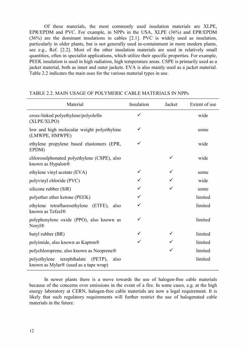
Of these materials, the most commonly used insulation materials are XLPE, EPR/EPDM and PVC. For example, in NPPs in the USA, XLPE (36%) and EPR/EPDM (36%) are the dominant insulations in cables [2.1]. PVC is widely used as insulation, particularly in older plants, but is not generally used in-containment in more modern plants, see e.g., Ref. [2.2]. Most of the other insulation materials are used in relatively small quantities, often in specialist applications, which utilize their specific properties. For example, PEEK insulation is used in high radiation, high temperature areas. CSPE is primarily used as a jacket material, both as inner and outer jackets. EVA is also mainly used as a jacket material. Table 2.2 indicates the main uses for the various material types in use.
TABLE 2.2. MAIN USAGE OF POLYMERIC CABLE MATERIALS IN NPPs
Material Insulation Jacket Extent of use
cross-linked polyethylene/polyolefin (XLPE/XLPO)
wide
low and high molecular weight polyethylene (LMWPE, HMWPE)
some
ethylene propylene based elastomers (EPR, EPDM)
wide
chlorosulphonated polyethylene (CSPE), also known as Hypalon®
wide
ethylene vinyl acetate (EVA) some
polyvinyl chloride (PVC) wide
silicone rubber (SiR) some
polyether ether ketone (PEEK) limited
ethylene tetrafluoroethylene (ETFE), also known as Tefzel®
limited
polyphenylene oxide (PPO), also known as Noryl®
limited
butyl rubber (BR) limited
polyimide, also known as Kapton® limited
polychloroprene, also known as Neoprene® limited
polyethylene terephthalate (PETP), also known as Mylar® (used as a tape wrap)
limited
In newer plants there is a move towards the use of halogen-free cable materials because of the concerns over emissions in the event of a fire. In some cases, e.g. at the high energy laboratory at CERN, halogen-free cable materials are now a legal requirement. It is likely that such regulatory requirements will further restrict the use of halogenated cable materials in the future.

13
REFERENCES TO SECTION 2
[2.1] GAZDZINSKI, R.F., DENNY, W.M., TOMAN, G.J. & BUTWIN, R.T., Ageing Management Guideline for Commercial Nuclear Power Plants — Electrical Cable and Terminations, Rep. SAND 96-0344, US Dept. of Energy, prepared by Sandia National Labs for the US Dept. of Energy, Albuquerque, NM (1996).
[2.2] HILL, B.R., STEED, O.T., “Harsh environmental qualification of cables for use in Sizewell ‘B’ PWR power station,” Proc. Int. Conf. on ‘Operability of nuclear systems in normal and adverse environments’, Lyon, 1989, Societé Française d’Energie Nucléaire, Paris (1990).

14
3. AGEING MECHANISMS
3.1. GENERAL FEATURES OF AGEING OF POLYMERS
3.1.1. Basic conditions for ageing to occur
The ageing of polymeric materials is dependent on three basic factors which are: the polymer system itself, the pre-service and service environmental conditions on this system, the time scale (generally long periods). The external jacket and the insulating materials are formulated organic compounds. They are made of a basic polymer (a macromolecular chain obtained by multiple replications of a unitary monomer) or co-polymer and of additives which provide the material with specific properties. These additives are mainly protective agents (anti-oxidants, thermal stabilizers, fire retardants), mineral fillers, plasticizers, oil (used to aid manufacture of the material), pigments etc. Some complex compounds may contain up to ten or fifteen different constituents. Variations in formulation can affect both the activation energy and rate of thermal ageing and the maximum dose for radiation ageing. The electrical cables inside the containment building of an NPP are exposed to various environmental conditions. The most important factors are temperature and ionizing radiation, to which should be associated the nature of the environment, typically the presence of oxygen in most reactor types and the presence of water vapour in some designs of BWR reactors (the relative humidity being possibly above 80%). Mechanical influences should also be considered, e.g. vibration, for cables connected to running machines; connection/disconnection operations during maintenance, installation anomalies where bending stresses are excessive, which may locally affect some cables. For I&C cables, electrical stresses are not significant in ageing, since this type of cable is exposed to voltages <1 kV. The electrical cables in NPPs are also used over very long periods of time, which can typically reach 40 to 50 years. The three basic factors for ageing are therefore present and will cause ageing of the polymeric materials of the cables. The consequences of this ageing on the required functional capability of cables need to be considered.
3.1.2. Basic effects of ageing
The environmental service conditions will induce chemical and/or physical processes at the molecular level of the material; these processes are the ageing mechanisms. The consequence at the macroscopic level is a slow and irreversible change in the properties (electrical, mechanical) of the material, which can lead to the functional failure of the cable. Typical macroscopic changes in the properties of common cable materials include: (a) decrease in the tensile elongation of the material, often associated with a decrease in the
tensile strength

15
(b) increase in the hardness or compressive modulus (particularly for materials commonly used as jackets)
(c) increase in the density (d) changes in the electrical properties, e.g. small increases in dielectric loss are observed in
some materials. In most cable types, the changes in electrical properties are not large. Loss of cable functionality is usually determined by the changes in mechanical properties, cracking of the insulation preceding electrical failure (i.e. loss of insulation resistance). PVC cables, however, may fail electrically during a DBE test before becoming severely embrittled. The ageing mechanism may include various elementary mechanisms which may have cumulative, competitive, synergistic and/or antagonistic effects. Two large categories of ageing mechanisms (chemical/physical) are usually distinguished, depending on whether they imply a change in the chemical structure or not of the macromolecular chains or the additives. The following sections describe the practical aspects of ageing and why ageing mechanisms need to be understood, how to identify ageing mechanisms and recommendations on how to carry out meaningful accelerated ageing tests.
3.2. UNDERSTANDING AGEING MECHANISMS
Ageing mechanisms are active when a sensitive/susceptible material is exposed to suitable environmental conditions. As a result, changes occur in material properties (ageing effects) which may cause changes/degradation in the functional characteristics of cable. Although the best scientific solution for appreciating the long term behaviour of cable materials would consist in removing cables after a 40 to 50-year operating period in an NPP, such a solution is generally unrealistic, except where samples are available from redundant circuits or from specific deposits of cable materials. Another possible solution would be to simulate ageing in an accelerated manner by carrying out in a few months (short term) what happens over long periods of time. In order to be satisfactory, accelerated ageing should include a fundamental concept — that the simulation of ageing must be representative. It is therefore necessary to select the conditions for the accelerated tests to simulate the ageing mechanisms involved in NPPs. Numerous studies over the past 20 years have generated a great number of examples which enable this key notion to be appreciated. Some examples of practical aspects of ageing mechanisms that need to be considered in accelerated ageing tests are given in the following subsections.
3.2.1. Use of a predominance diagram
Figure 3.1 is a schematic representation of the different ageing domains which can occur in a cable material, plotted as a function of dose rate and temperature. Each of the domains is separated by boundaries for which it is possible to establish equations, in a region defined by temperature and dose rate. The ageing mechanisms involved in the various domains are not identical. The relevant domain depends on the temperature and radiation dose rate. Domain I is controlled by a homogeneous radiation ageing process; Domain II is

16
controlled by homogeneous thermal ageing; Domain III is a “mixed” ageing process, both radiation and thermal and represents a boundary region between Domains I and II. Domain IV represents the region dominated by diffusion-controlled processes. The major condition for the validity of accelerated ageing is that accelerated ageing conditions in the graph should be in the same domain as the conditions for natural ageing. For example, if the ageing conditions in the NPP are represented by the dark area in Figure 3.1, then accelerated ageing should be carried out in Domain I [3.1, 3.2]. If the accelerated ageing is not carried out in the same domain, then additional uncertainties are introduced which need to be addressed using other information, such as condition monitoring, or by including additional margin.
In (I
)
III
IV
III
1/T
Oxidation controlled by defusion
Thermolysis
Radiolysis
FIG. 3.1. Schematic diagram showing the dominant ageing mechanisms for different conditions of dose rate I and temperature T (Domain (III) represents the
boundary between domains (I) and (II). Ageing mechanism = f (In I, 1/T) [3.1, 2.2]. The black square represents the service conditions in an NPP.
3.2.2. Arrhenius diagram
Arrhenius’s law is often used as a physical model for lifetime prediction during thermal ageing. It assumes that the rate of the thermal ageing mechanism decreases with the inverse of the temperature, such that the rate constant k can be described by the following equation.
(In k = In A - Ea/RT)
where A is a constant for the material being tested, Ea is the activation energy for the process, R is the gas constant and T is the absolute temperature. A plot of the reaction rate on a log

17
scale against 1/T should yield a straight line whose slope is determined by the activation energy Ea. The activation energy controls the temperature sensitivity of the degradation rate. Carrying out accelerated ageing over a large range of temperatures will sometimes show a “break point” in the plot, which corresponds to a change in the kinetic regime. The value of the activation energy is not constant over the whole temperature domain [3.3]. An example of this effect in a cable material is shown in Figure 3.2. Most examples where changes in slope have been observed show lower values of Ea at lower temperatures. In such conditions, an extrapolation based on the data measured at high temperature would give a significant underestimation of the ageing at lower temperatures. It is generally recommended that the interval between the lowest temperature used in the accelerated ageing test and the temperature of use should not exceed 25°C, if possible [3.4]. The value of activation energy which is used for acceleration ageing tests is of major importance in obtaining representative data. The measurement of activation energy values is discussed in Annex A.1. Guidance for the application of the Arrhenius law to ageing of polymers is given in IEC 216 [3.4].
10-5
2.510 / T3 (K )-1
k(l /
h)
2.7 2.9 3.12.3
10-4
10-3
10-2
96, 6kJ / mol{23kcal / mol}
54, 6kJ / mol
( C)o130 70100
10-1
CSM
FIG. 3.2. Arrhenius plot for thermal degradation rate for CSPE material [3.3].

18
3.2.3. Plasticized PVC: Competition between HCl elimination and evaporation of plasticizers
For thermal ageing at temperatures below 70–80°C in the absence of radiation, themain ageing mechanism for plasticized PVC is evaporation of plasticizers from the surface of the external sheath of the cable. At higher temperatures (>80°C) and under irradiation, this mechanism is in competition with intramolecular elimination of hydrochloric acid (HCl) from the macromolecular chains of PVC. Thus, increasing of temperature of the accelerated ageing reduces the validity of the ageing simulation.
3.2.4. Semi-crystalline polymers: Ageing through a physical transition
Some of the polymeric materials used in cables are semi-crystalline, with a crystalline melting region close to the temperature range used in service. Studies have shown the influence of the crystalline phase on physical properties, particularly for polyethylene based materials. For this type of material, care must be taken in extrapolation of data from accelerated thermal ageing tests. If the extrapolation is through the crystalline melting region, then the Arrhenius equation will not be valid and the accelerated tests will not be a representative simulation of natural ageing. In accelerated radiation ageing, semi-crystalline polymers (such as XLPE) will often show a reverse temperature effect, with ageing occurring more rapidly at lower temperature than at higher temperature. This is because of the complex “repairing” mechanism of the macromolecules when recrystallisation takes place [3.5, 3.6]. This is discussed further in Annex A.2.
3.2.5. Compatibility of materials: The constitution of the cable
For some cable configurations, the external jacket is in direct contact with the insulation material. In the specific case of plasticized PVC cables, this can lead to diffusion of plasticizers from one material to another. This is a physical ageing mechanism (mass transfer). This mechanism is not observed when a solid metallic screen is placed between the two materials, but can occur if the metallic screen is braided. The degradation observed will not be the same when ageing is performed separately on dumbbells cut from the jacket or insulation PVC materials, compared with ageing of complete cable samples. The diffusion of plasticizers has also been observed with polyethylene external jacket/PVC insulation and PVC jacket/PE insulation material systems. Materials compatibility may also affect connectors or terminations. Interaction between the degradation products of the jacket and insulation materials can also occur, affecting the observed behaviour, particularly in accelerated tests. This is the case for PVC jacketed cables with PE insulation, which are radiation aged or thermally aged at temperatures >80°C, when HCl elimination is a dominant mechanism. The selected sample geometry (pre-cut dumbbells, complete cable) for an ageing study may strongly affect the ageing mechanisms because of interaction between the cable components. A study highlights that the activation energy of a CSPE material depends upon the sample geometry during thermal ageing [3.7].

19
3.3. IDENTIFICATION OF THE MAIN AGEING MECHANISMS
In considering the main ageing mechanisms in cable materials, we can distinguish between chemical ageing mechanisms, which affect the molecular structure, and physical ageing mechanisms, which affect the composition of the compound.
3.3.1. Chemical ageing mechanisms
The main chemical ageing mechanisms are the following: Scission of macromolecular chains: two new chains are created after the breaking up of one. It is usually a scission of alkoxyl or peroxide radicals. This is shown schematically below.
Cross-linking reactions: cross-linking corresponds to the formation of a covalent link of two adjacent macromolecules. As the number of cross-links increases, the cross-link density increases as shown schematically below, forming a three dimensional network.
Oxidation reaction: this is a free radical chain mechanism whose classical series of reaction steps can be found in numerous reference works (see Annex A.3). The reaction scheme is summarized below. (a) initiation step = formation of free radicals (b) propagation step = formation of peroxy radicals and hydroperoxide (c) chain branching step = decomposition of hydroperoxide (d) termination step = deactivation of radicals in inert products (alcohol, acid ...). The initiation step leads to the formation of reactive species, i.e. radicals, because of the initial break of a covalent link under the effect of temperature and/or radiation. Oxidation leads both to chain scission and cross-linking, dependent on the detailed kinetics of the individual steps in the oxidation chain reaction. These kinetics are strongly dependent on the additives present in the polymeric compound and will therefore vary with the detailed formulation of the material. Process controlled by oxygen diffusion: the kinetics of ageing are governed by the diffusion of oxygen when the free radical initiation rate is faster than the rate of dissolved oxygen diffusion in the polymeric material. This behaviour leads to a concentration profile in oxidation products in the material thickness (heterogeneous degradation). An oxidized surface layer with a cross-linked core is observed. Oxygen diffusion controlled processes depend on

20
the oxygen permeability of the polymer, the radiation dose rate, and the sample thickness. Diffusion-limited oxidation is the first type of radiation dose rate effect identified in polymer ageing. This diffusion-limited process can also occur in thermal ageing of polymers. Synergistic effect: this is observed in a number of polymeric materials when the combined effects of environmental conditions are higher than the individual effects of the conditions applied separately. It is particularly evident in combined thermal and radiation ageing for some polymers, but can also be observed for other conditions, e.g. moisture and radiation in polyurethane and polyimide materials. Elimination of hydrochloric acid: this corresponds to the elimination of a molecule of hydrochloric acid (dehydrochlorination) from the macromolecular chain of PVC. A similar mechanism occurs in fluorinated polymers, with the elimination of hydrofluoric acid (HF). It goes together with the formation of conjugated polyenes. When the degradation is advanced enough, the material becomes coloured.
3.3.2. Physical ageing mechanisms
The main physical ageing mechanisms are the following: Evaporation of plasticizers: plasticizers will evaporate at the surface of the material. The surface is then replenished by plasticizer diffusion from the core as shown schematically below. There can be competition between these two kinetic regimes (evaporation and diffusion), depending on temperature. This ageing mechanism is of particular concern in PVC based materials, which usually have a high plasticizer content.
Migration of plasticizers: this phenomenon appears in multilayer cables using plasticized materials. The migration of plasticizers occurs until equilibrium is reached corresponding to a uniform distribution of each plasticizer, in each material [3.8].
3.3.3. Practical tools for identification of ageing mechanisms
Identification of the dominant mechanisms can be conducted on samples that have either undergone an accelerated laboratory ageing programme or that have been taken from an NPP. The most common characterization methods are the following: (a) mechanical tests: elongation at break, tensile strength, compressive modulus, (b) electrical measurements: insulation resistance, dielectric strength, dielectric loss,

21
(c) physical and chemical tests: FT-IR spectroscopy, oxidation induction time and temperature (OIT & OITP), swelling ratio, gel fraction, mass loss, visco-elasticity properties, NMR, density.
Cross-linking and chain scission modify the macromolecular chains of the material. The consequence is a change in the mechanical properties and of the swelling ratio of the three dimensional molecular network. For example, the radiation ageing of EPR leads to a decrease of the elongation at break and of the swelling ratio, and also to an initial increase of the tensile strength. The change in these three properties indicates that the dominant ageing mechanism is cross-linking. In the case of plasticized PVC, the evaporation of plasticizers can be followed by gravimetry measurements (mass loss). The identification of an ageing mechanism is made possible through following several properties of the material with time. In some situations, variations of some properties such as elongation at break for polyolefins stabilized by anti-oxidants (existence of an induction period) are “pass/fail” type. After an induction time, the property decreases strongly (end of life of the material). such properties should not be selected as a sensitive parameter to follow the ageing of the material: other properties should be used (see Section 6). For ageing mechanisms which lead to heterogeneous degradation, it is important to select tools which allow a “local” analysis on the thickness of the material. Techniques such as DMA Pin-Point, two dimension FT-IR analysis and micro-indentation are adapted to carry out such investigation. These types of techniques enable the properties of the material to be evaluated as a function of depth into the material (see Annex A.4).
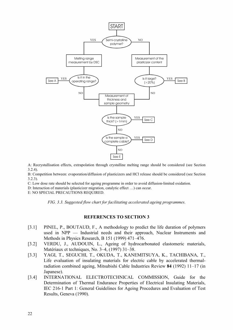
3.4. AN APPROACH TO FACILITATE ACCELERATED AGEING STUDIES
A simplified flow chart is shown in Figure 3.3 which provides a suggested route for avoiding some of the common mistakes that can occur in implementing accelerated ageing studies. This diagram can be applied to all of the polymeric materials that are usually used in commercial electrical cables. By tracing through the flow chart, the main pitfalls commonly experienced in accelerated ageing can be avoided and the results will be more representative of natural ageing. The suggested approach involves a small amount of initial checks carried out before the start of an accelerated ageing programme to identify the potential problem areas.
22
START
Semi-crystallinepolymer?
Melting rangemeasurement by DSC
Is it in theoperating range?See A See B
See C
See D
See E
Is it large?(>20%)
Is the samplethick? (>1mm)
Is the sample acomplete cable?
Measurement of theplasticizer content
Measurement ofthickness and
sample geometry
YES
YES YES
YES
YES
NO
NO NO
NO
NO
A: Recrystallisation effects, extrapolation through crystalline melting range should be considered (see Section 3.2.4). B: Competition between: evaporation/diffusion of plasticizers and HCl release should be considered (see Section 3.2.3). C: Low dose rate should be selected for ageing programme in order to avoid diffusion-limited oxidation. D: Interaction of materials (plasticizer migration, catalytic effect …) can occur. E: NO SPECIAL PRECAUTIONS REQUIRED.
FIG. 3.3. Suggested flow chart for facilitating accelerated ageing programmes.
REFERENCES TO SECTION 3
[3.1] PINEL, P., BOUTAUD, F., A methodology to predict the life duration of polymers used in NPP — Industrial needs and their approach, Nuclear Instruments and Methods in Physics Research, B 151 (1999) 471–476.
[3.2] VERDU, J., AUDOUIN, L., Ageing of hydrocarbonated elastomeric materials, Matériaux et techniques, No. 3–4, (1997) 31–38.
[3.3] YAGI, T., SEGUCHI, T., OKUDA, T., KANEMITSUYA, K., TACHIBANA, T., Life evaluation of insulating materials for electric cable by accelerated thermal-radiation combined ageing, Mitsubishi Cable Industries Review 84 (1992) 11–17 (in Japanese).
[3.4] INTERNATIONAL ELECTROTECHNICAL COMMISSION, Guide for the Determination of Thermal Endurance Properties of Electrical Insulating Materials, IEC 216-1 Part 1: General Guidelines for Ageing Procedures and Evaluation of Test Results, Geneva (1990).

23
[3.5] GILLEN, K.T., CLOUGH, R.L., WISE, J., MALONE, G.M., Explanation of enhanced mechanical degradation for radiation-aged polyolefins as the temperature is decreased, Rep. SAND 94-1104C, Sandia National Laboratories, Albuquerque, NM (1994).
[3.6] BURNAY, S.G., DAWSON, J., “Reverse temperature effect during radiation ageing of XLPE cable insulation material”, (Proc. of Int. Conf. on Ageing Studies and Lifetime Extension of Materials”, Oxford, 1999) Kluwer/Plenum Press, London (in press).
[3.7] CARLIN, F., LAURENT, J.P., GAUTHIER, G., CALMET, J.F., The effect of the environment on the ageing of electric cables, results from a study related to Hypalon and EPR parts of HN 33 S25 cable type, paper presented at 1995 IAEA specialists meeting on Effectiveness of methods for the detection and monitoring of age related degradation in Nuclear power plants, San Carlos de Bariloche, Argentina.
[3.8] BENHABILES, K., PINEL, B., Plasticizers diffusion kinetics for PVC cables: Correlation between electrical properties and plasticizer migration, paper presented at 1995 Congrès JICABLE, June, Versailles.

24
4. MANAGING AGEING OF CABLES THROUGH ENVIRONMENTAL QUALIFICATION
Cable ageing management is aimed at ensuring that cables within an NPP are capable of carrying out their function under expected service conditions over the lifetime of the plant. For some cables important to safety, service conditions include postulated accident and post-accident conditions, commonly referred to as design basis event (DBE) conditions. The operational requirements of I&C cables as components of circuit systems include the dielectric properties of the conductor insulation, e.g. insulation resistance between conductors or between conductors and earth. Qualification establishes the ability of the cables to function during DBE conditions and should define application constraints, including ageing constraints. Qualification manages ageing to the extent that these constraints (e.g. ambient temperature, qualified life, qualified condition) are applied to installed devices. Supplementary ageing management activities refine or verify these constraints and thus provide confidence that in-plant condition is within the constraints established by the design or qualification programme. This section provides an overview of existing environmental qualification (EQ) methods that provide the basis for managing the ageing of in-containment cables important to safety. The qualification methods outlined in this section are primarily intended for application to cables that are required to be functional under service conditions including DBE. The management of ageing of cables that are not required to function in a DBE can use the same approach, without a DBE test.
4.1. EXISTING QUALIFICATION METHODS
4.1.1. Objectives
The objective of environmental qualification is to provide reasonable assurance that the cable will operate or demand, under specified service conditions, to meet system performance requirements. The specified service conditions include both normal operating conditions and, where applicable, DBE conditions at the end of its expected service life. EQ can be performed on a generic basis (e.g. by application of a general standard such as references [4.1–4.4] or on a plant specific basis developed around predicted worst case accident conditions. Initial qualifications (type testing) is used for establishing the environmental qualification of a new cable before installation. The basic objective of initial qualification is to demonstrate that the cable is qualified for the specific service conditions, including normal and abnormal operation, and to define application constraints. The initial qualification is often use to establish a qualified life. An alternative approach, which is also used, is to establish a qualified condition. Qualified life is the period of time under normal operational conditions when ageing does not prevent satisfactory performance of the cable during a subsequent DBE condition.

25
Qualified condition is the condition of a cable expressed in terms of a measurable condition indicator(s) for which it has been demonstrated that the cable will meet its functional requirements. It is independent of elapsed time.
4.1.2. Environmental qualification
Environmental qualification can be achieved by any appropriate combination of the following approaches. (a) An EQ test on samples representative of the cables to be installed (type test). (b) Application of relevant experience with the same materials in similar applications. (c) Analysis based on extrapolation of engineering data and operating experience. An EQ test normally includes the following activities to address ageing: (a) Preparation of the qualification procedure including the functional requirements during
normal plant operation, abnormal plant operation and DBE. Essential elements that are usually included in the procedure are:
identification of the cable insulation material; a review of past operating experience on the same material (if available); information on the material’s ageing behaviour and sensitivity to various environmental conditions; reference measurements.
(b) Functional testing before subjection to environmental stresses,
(c) Accelerated ageing, including evaluation of long term behaviour, and
(d) DBE testing and, where applicable, post-DBE testing, including functional monitoring. This type of test is usually used to establish a qualified life. As an alternative to the use of a time-based qualified life, a condition-based qualified life may be more appropriate. To establish a condition-based qualified life, the test cable is artificially aged to a predetermined condition, for example to an elongation of 50% absolute. The subsequent qualification process is identical to that for a time-based qualified life in that the test cable is subjected to a functional test under simulated accident conditions. In this case, however, once the cable is qualified, it is acceptable for continued service as long as it has not degraded to the point where its condition is below the qualified condition, regardless of the amount of time it is in service. Since the functional condition of the cable is the ultimate concern, a condition-based qualified life would appear to be a more reasonable requirement. The disadvantage for a condition-based qualified life is that periodic monitoring is required to verify that the cable condition is still acceptable. This could be problematic if a destructive test such as elongation is used. However, the advantage is that cables that have not experienced significant degradation would not need to be re-evaluated to extend their qualified life or replaced after a certain period of time. In addition, the uncertainties introduced by analytical modelling are avoided.
4.1.3. Concerns in EQ testing
If the goal of the initial qualification test is to demonstrate a qualified life equivalent to a relatively long installed life (e.g. 30 to 40 years), the accelerated ageing may have to be performed with very high acceleration factors to ensure completion in a reasonable period of time. This may require that the accelerated ageing be performed at high temperatures and/or

26
radiation dose rates, which introduce a high degree of uncertainty in the prediction of the qualified life or in the establishment of a qualified condition. In this connection, Reference [4.5] gives examples of several different insulation materials tested in both long term NPP conditions and under short term accelerated tests of the type used in qualification. Although most materials performed satisfactorily, some specific materials failed the DBE tests after radiation doses much lower than predicted. There are several ways in which these uncertainties can be reduced, including: (a) to initially qualify for a life shorter than the expected service life of the plant and then
extend the qualified life by activities after installation,
(b) to initially qualify for a life equal to the expected service life of the plant, using very high acceleration factors, then perform supplementary qualification testing after installation, using moderate acceleration factors and long term duration in order to provide increased confidence in (or revise) the qualified life.
There are also uncertainties in establishing a qualified condition. If the accelerated thermal ageing is carried out at too high a temperature, the ageing mechanisms will not be the same as those seen in service. A similar concern arises in accelerated radiation ageing, where heterogeneous oxidation can occur at high dose rates, particularly in the whole cable samples used for DBE tests. In both cases, the aged material which has been demonstrated to survive a DBE will not be representative of cables aged in service and the qualified condition may not be valid. The artificial ageing section of the qualification programme needs to take into account all of the potentially important ageing conditions to which the cable will be subjected during its installed life (see Section 3). Heat (thermal ageing) and ionizing radiation are always important environmental factors for cables installed inside containment. Other environmental factors, e.g. vibration, humidity, may be important, depending on the individual plant design and on the location of the cable. In addition, the sequence in which the cable is subjected to the various environmental factors has been shown to be important for simulating the effects of ageing. Synergism resulting from a combination of environmental factors applied simultaneously may increase the ageing degradation further than the application of the environmental factors in sequence. These aspects of the accelerated ageing programme and DBE testing are briefly discussed in the following sections. 4.1.4. Accelerated thermal ageing
Thermal ageing is always present, to some degree, for cables installed inside containment. Accelerated thermal ageing is achieved by exposing the cables to temperatures significantly higher than the expected service temperature. The assumption of an Arrhenius relationship between temperature and rate of degradation is typically used for determination of the acceleration factor (see Section 3.2.2). A qualification margin is applied in the establishment of the qualified life. This margin is dependent on a number of factors, including

27
(a) knowledge of the cable temperature during operation. Less margin is needed if the temperature is controlled (and measured) throughout the cable’s qualified life,
(b) knowledge of the characteristics of the materials from which the cable insulation is constructed, especially access to measured activation energies within the actual temperature range of service,
(c) test tolerances, e.g. the tolerances on temperature in the working space of the dry heat test chamber, and
(d) the number of samples tested. Several studies have shown that the activation energy and degradation rate may vary with the composition of the insulation material (fillers, additives, etc) and with the temperature. It is recommended that the activation energy of the cable insulation materials be measured as part of the preparation for the testing. Values taken from studies based on similar, but not identical materials or at temperatures other than the specific application temperature may be of limited use. In cases where such values are used instead of measurements on the actual cable materials, a high degree of conservatism is required. Test temperature tolerances are stated in standards used for climatic testing, e.g. IEC 60068-2-2 for high temperature testing [4.6]. Studies of the relationship between required qualification margin and the number of samples tested show that a high margin may be needed to account for the deviation between individual cable samples, if very few samples are used in the qualification test. However, the margin needed can be significantly reduced by increasing the number of samples tested [4.7]. The accuracy of the qualified life established through laboratory testing is limited by the factors discussed above, but also by the inaccuracy inherent in the application of the Arrhenius formula to a complex component. The inaccuracy grows with increasing acceleration factor; that is with increasing difference between test temperature and operating temperature. In Sweden, a limit of 250 on the acceleration factor to be used for establishment of qualified life is included in some documents [4.8]. Even when limiting the acceleration factor to 250, the temperature used for the thermal ageing may be too high for certain materials. In establishing a qualified condition, care must be taken that the accelerated thermal ageing is carried out at a temperature where the ageing degradation mechanism is the same as that seen in service.
4.1.5. Accelerated radiation ageing
The radiation ageing component of an accelerated ageing test normally includes subjecting the test specimen to the total expected lifetime dose (before DBE) in a short time, which means a much higher dose rate than under normal operating conditions. The acceleration factor is defined by the ratio between the dose rate used in the artificial ageing and the dose rate in operating conditions.

28
The qualification margin applied in radiation ageing for establishing of the qualified life depends on (a) knowledge of the dose rate during normal operation. Less margin is needed if the dose
rate is controlled (and measured) throughout the cables qualified life,
(b) knowledge of the dose rate effect on the cable insulation materials,
(c) test tolerances, and
(d) the number of samples tested. For many insulation materials, the degradation due to a specific total radiation dose depends on the dose rate. For most cable insulation materials, oxidation is the dominant degradation mechanism during long term ageing. The observed degradation during accelerated ageing will be dependent on whether oxygen is able to diffuse into the cable material during the test period. Diffusion limited oxidation effects are described in more detail in Ref. [4.9]. Unless it has been proven by tests that the dose rate effect is negligible, it is recommended that the dose rate be limited in the artificial ageing test. Very low dose rates (20–30 Gy/h) have been found necessary for testing certain materials particularly sensitive to the dose rate. In establishing a qualified condition, care must be taken to avoid the development of heterogeneous oxidation which occurs when diffusion limited oxidation takes place. This is a particular concern in the whole cable samples used for DBE testing.
4.1.6. Other environmental conditions
For most applications of cables inside the containment of NPPs, humidity is not a factor. The relative humidity is often low in the containment of PWR reactors. Cables in the wet well of some designs of BWR reactors may, however, be exposed to high relative humidity, typically 80%, during normal operation. High humidity may accelerate the thermal ageing since hydrolysis adds to the rate of degradation of the insulation material. Cables in locations that are normally not subjected to humidity will be exposed to high humidity during a DBE. For cables that are required to maintain their dielectric properties during post-DBE, humidity may be a factor that needs to be considered when establishing qualification. Most cables in the containment of an NPP are not subjected to significant vibration under normal operating conditions. However, vibration may have to be taken into account if cables are attached to vibrating machinery or if they may be subjected to vibration due to abnormal operation conditions. The fatigue effect of vibration is not significant but vibration may increase the adverse effects of ageing by creating small, not visually detectable, cracks in thermally aged insulation that may be detrimental to the dielectric behaviour when the cables are exposed to high-pressure steam in a DBE [4.10]. Installation and maintenance activities may affect the mechanical integrity of cables by inadvertent bending, connection and disconnection, cutting for mounting of accessories, cable pulling, etc. Such mechanical stresses can be managed within the scope of maintenance activities.

29
4.1.7. Influence of combined and sequential environmental conditions
In some cases, significant synergism increases the rate of degradation of cable insulation materials as a result of simultaneous exposure to two or more environmental conditions, e.g., high temperature and ionizing radiation. In such cases, it may be necessary to combine the conditions in the accelerated ageing process or add margins to account for the known synergistic effects. In sequential testing, the order in which the thermal and radiation conditions are applied may be important. Ionizing radiation followed by thermal ageing has in various studies been found to be more conservative than thermal ageing followed by ionizing radiation for many of the polymers used in cable insulation and jacket materials. Most existing EQ tests carry out thermal ageing first and then apply a radiation ageing component, often combined with the DBE radiation dose. The qualification margin used needs to be sufficiently conservative to allow for any effects of sequential testing of this type. It is not common practice, and for normal positions not important, to include vibration ageing as part of the initial environmental qualification of cables. If, however, the specific condition of a certain cable location is such that it is desirable to include vibration in the qualification, the vibration test should be performed either intermittently during the thermal and radiation ageing or at the end of the thermal and radiation ageing [4.10].
4.1.8. DBE and post-DBE testing
The DBE test (accident simulation test) normally includes a gamma radiation exposure, which represents the total accident and post accident irradiation dose, followed by a thermodynamic test in steam under high pressure. The radiation dose in the DBE test usually includes significant qualification margins. The testing is carried out at high dose rates, between 1 kGy/h and 10 kGy/h. The ambient temperature in the test chamber may be higher than in actual conditions (e.g., 70°C) in order to take into account ohmic heating, although this is not an issue for I&C cables. The thermodynamic test is normally designed on the basis of the specific conditions of the plant and includes a steam temperature/pressure profile as a function of time that envelopes various postulated accident situations. LOCA (loss of coolant accident) simulation, with or without chemical spray, is typically taken into account in establishing the test profile. In some cases MSLB (main steam line break) simulation and, if applicable, post-LOCA and/or post-MSLB-simulation which may last for a long period (up to one year), may also be addressed by the test profile. Simulation of post-DBE may include acceleration of thermal effects by testing at a higher temperature than in actual conditions and application of the Arrhenius formula. It is reasonable to believe, though not experimentally verified, that keeping the relative humidity at a high level at the high test temperature would also accelerate the humidity effect on ageing to a similar degree as the thermal effect. The functional characteristics (dielectric behaviour) of the test cable are monitored during the thermodynamic test and form the basis for the pass/fail outcome of the test. Mechanical and electrical measurements may be performed after the radiation exposure but do
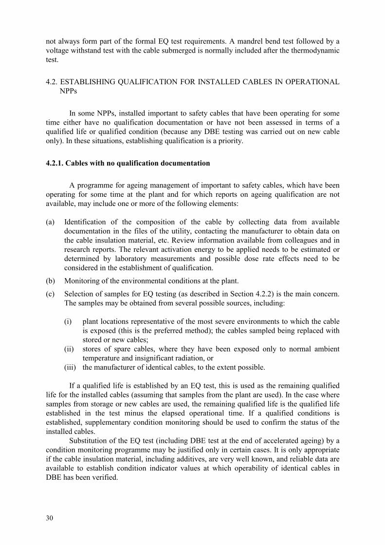
30
not always form part of the formal EQ test requirements. A mandrel bend test followed by a voltage withstand test with the cable submerged is normally included after the thermodynamic test.
4.2. ESTABLISHING QUALIFICATION FOR INSTALLED CABLES IN OPERATIONAL NPPs
In some NPPs, installed important to safety cables that have been operating for some time either have no qualification documentation or have not been assessed in terms of a qualified life or qualified condition (because any DBE testing was carried out on new cable only). In these situations, establishing qualification is a priority.
4.2.1. Cables with no qualification documentation
A programme for ageing management of important to safety cables, which have been operating for some time at the plant and for which reports on ageing qualification are not available, may include one or more of the following elements: (a) Identification of the composition of the cable by collecting data from available
documentation in the files of the utility, contacting the manufacturer to obtain data on the cable insulation material, etc. Review information available from colleagues and in research reports. The relevant activation energy to be applied needs to be estimated or determined by laboratory measurements and possible dose rate effects need to be considered in the establishment of qualification.
(b) Monitoring of the environmental conditions at the plant.
(c) Selection of samples for EQ testing (as described in Section 4.2.2) is the main concern. The samples may be obtained from several possible sources, including: (i) plant locations representative of the most severe environments to which the cable
is exposed (this is the preferred method); the cables sampled being replaced with stored or new cables;
(ii) stores of spare cables, where they have been exposed only to normal ambient temperature and insignificant radiation, or
(iii) the manufacturer of identical cables, to the extent possible. If a qualified life is established by an EQ test, this is used as the remaining qualified life for the installed cables (assuming that samples from the plant are used). In the case where samples from storage or new cables are used, the remaining qualified life is the qualified life established in the test minus the elapsed operational time. If a qualified conditions is established, supplementary condition monitoring should be used to confirm the status of the installed cables. Substitution of the EQ test (including DBE test at the end of accelerated ageing) by a condition monitoring programme may be justified only in certain cases. It is only appropriate if the cable insulation material, including additives, are very well known, and reliable data are available to establish condition indicator values at which operability of identical cables in DBE has been verified.

31
4.2.2. Cables with undefined qualified life or condition
Some NPPs may have important to safety cables which have been operating for some time and for which a report on EQ testing is available that includes some accelerated ageing (thermal and radiation) but does not define a qualified life. A programme for ageing management of such cables may include the following elements: (a) Determine (preferably by measurements) the values of parameters relevant for the
calculation of the acceleration factors for the artificial thermal and radiation ageing (e.g., activation energy for the insulation materials). Some cables have different materials in the jacket and in the conductor insulation. In this case, the value of the activation energy of the conductor insulation should normally be used, since the integrity of the conductor insulation is normally of prime importance.
(b) Determine (preferably by measurements) the temperature and radiation levels during normal operation in areas representative of the cable locations. Identify the qualification margins included in the original EQ test.
(c) Calculate the acceleration factors for the reported EQ tests.
(d) Calculate the qualified life or establish the qualified condition.
It may be necessary to extend the qualified life. In this case, additional EQ laboratory testing (accelerated ageing plus DBE testing) may need to be performed. CM programmes supplementing laboratory testing may be included to provide additional assurance that the actual degradation of the cables is well monitored and managed. An alternative, which may be possible, is to establish a qualified condition by repeating the accelerated ageing segment of the original EQ report and measuring the condition of the cable. This would only be feasible if samples of unaged cables are available for such tests.
4.3. PRESERVING QUALIFICATION
EQ is the primary means of addressing ageing of important to safety cables and normally includes worst case environmental conditions. This means that large qualification margins are included for most cables in NPPs which help to offset some of the uncertainties inherent are existing EQ methods. Supplementary activities (environmental monitoring, cable CM, additional accelerated ageing tests) are performed to verify application constraints defined by the initial EQ of a cable and to increase the confidence in the qualified life or qualified condition initially established. The basis for the qualified life established through initial EQ test methods using high acceleration factors can be improved substantially by various supplementary cable testing and monitoring activities. Where a qualified condition is used, condition monitoring would be required to confirm that installed cables have not degraded beyond the qualification condition. These activities can be performed after installation to increase confidence in the qualified life or qualified condition, and/or to extend the qualified life of the cable. They can be used separately or in combination, depending on the qualification status and plant situation. These activities are briefly described in the Sections 4.3.1 to 4.3.3.

32
4.3.1. Monitoring of actual environmental conditions in the plant
The qualified life established in the initial environmental qualification is based on estimates of the environmental conditions to which the cables will be exposed after installation. Qualification margins are normally included in such estimates to take into account uncertainties in the environmental conditions predicted. If the ageing management programme includes continuous or intermittent monitoring of the environmental conditions (primarily temperature and ionizing radiation) in areas representative of the location of the cables, the margins can be limited and an adjustment of the qualified life can be made. This adjustment can be periodically after installation, based on the actual environmental conditions (pacing). Methods for environmental monitoring are described in Section 5.2.
4.3.2. Condition monitoring (CM)
Most qualifications indicate that the tested cables can withstand normal environments for long periods. Monitoring of the condition of cables in the field can be used to verify that ageing is not proceeding more rapidly than expected and that the cable materials retain their mechanical properties. If normal environments and cable service conditions are severe, then more care is required in managing the ageing of the cable. If a CM programme is to be used, it is necessary to produce the baseline data for such a programme during the initial qualification or during additional ageing tests. The value of a condition indicator (CI), measured at the end of the qualified life, before a successful DBE test, constitutes the condition of the cable at which the operability has been verified in the qualification test. An installed cable is at the end of its qualified life when this value of the CI is reached. The purpose of the CM programme is to verify that the qualified condition has not been exceeded. To accomplish this, the value of the CI at the end of the qualified life, along with the variation of the CI value with time, needs to be known. The selection of one or more appropriate condition indicators depends on the cable insulation material. Detailed information for selection of indicator(s), sampling of cables from installations or deposits for monitoring, selection of monitoring intervals, etc. is given in Section 5. Any CM programme used as part of a cable ageing management programme is likely to be limited to a small number of cables of concern, mainly in hot spot areas. Identification of such cables is discussed in Section 5.
4.3.3. Additional accelerated ageing tests
The time available for accelerated ageing at the initial qualification is often restricted and does not allow long term artificial ageing. Therefore the predicted qualified life may be limited or high acceleration factors may be used which introduce considerable uncertainties in the estimation of the qualified life. A high degree of conservatism is then normally used in the prediction of the qualified life. After installation, an improved assessment of qualified life and its possible extension can be obtained by additional laboratory testing of cables from storage or of installed cables that are removed and replaced by new cables. Available time will then allow thermal and radiation ageing for a long duration at more moderate acceleration factors (moderate temperatures and radiation dose rates), followed by DBE testing. The time available may also allow more accurate determination of relevant activation energies for the thermal ageing.

33
Alone or together with the results of monitoring of the actual environmental conditions, additional accelerated ageing tests after installation can be used to reduce the uncertainty in the predicted qualified life. Additional accelerated testing may also be used to reduce uncertainties in qualified condition. Supplementary testing on samples aged with lower acceleration factors than those usually used in EQ testing can help improve confidence that the qualified condition is representative of the ageing of the cable in the plant. In some plants, cable deposits were installed during the installation of new cables. The deposit cables are used in a programme for periodically monitoring the condition of the installed cables and revising the qualified life. Samples for the deposit cables are taken out at predetermined intervals (well before the end of the current qualified life or qualified condition) and subjected to accelerated laboratory ageing and DBE testing. If this testing shows that the cables still retain their required dielectric and other characteristics in DBE after the accelerated ageing, a revised qualified life is established for the installed cables. The procedure may then be repeated well before the end of the revised qualified life, etc. Activities performed subsequent to the initial EQ to extend qualification for an additional period of time are commonly referred to as “on-going qualification”. Instead of deposit cables, installed cables that are removed and replaced with cables from the storage may be used for testing. Where the qualified condition approach to EQ has been used, supplementary accelerated ageing tests may be used to establish the dependence of the selected condition indicators on the level of ageing.
4.3.4. Examples
An example of supplementary ageing management activities currently in use is described in Annex B2 and an example of a programme aimed at establishing qualification of unqualified cables is described in Annex B3.
REFERENCES TO SECTION 4
[4.1] INSTITUTE OF ELECTRICAL & ELECTRONIC ENGINEERS, IEEE Standard 323-1983 IEEE Standard for Qualifying Class 1E Equipment for Nuclear Power Generating Stations, The Institute of Electrical and Electronics Engineers, Inc., New York (1983).
[4.2] INSTITUTE OF ELECTRICAL & ELECTRONIC ENGINEERS, IEEE Standard 383-1974 IEEE Standard for Type Test of Class 1E Electric Cables, Field Splices, and Connections for Nuclear Power Generating Stations, The Institute of Electrical and Electronics Engineers, Inc., New York (1974).
[4.3] NORME FRANÇAISE NF M 64-001 (Nov 1991), Procédure de qualifications des matérials électriques installés dans l’enceinte de confinement des réacteurs à eau sous pression et soumis aux conditions accidentelles, Association Française de Normalisation, Paris.
[4.4] INTERNATIONAL ELECTROTECHNICAL COMMISSION, Qualification of electrical equipment of the safety system for nuclear power plants, IEC 780, Geneva (1984).

34
[4.5] ROST H., BLEIER, A., BECKER, W., Lifetime of cables in nuclear power plants, Proc. Int. Conf. on ‘Operability of nuclear systems in normal and adverse environments’, Lyon, Sep 18–22 1989, Volume 2, Société Française d’Energie Nucléaire, Paris (1990).
[4.6] INTERNATIONAL ELECTROTECHNICAL COMMISSION, Publication 60068-2-2 (1974-01), Environmental Testing — Part 2: Tests. B: Dry Heat, Geneva (1974).
[4.7] SPÅNG, K., Methodology for artificial ageing of electrical components in nuclear power plants. Results of experimental studies, SKI Technical Report 93:39, Swedish Nuclear Power Inspectorate, Stockholm (1993).
[4.8] SPÅNG, K., STÅHL, G., Elkomponenter I kärnkraftverk, Hantering av äldring (Electrical components in nuclear power plants, Handling of ageing) Ingemansson Technology Report H-14061 r-l, Ingemansson Technology AB, Göteborg (2000) (in Swedish).
[4.9] INTERNATIONAL ELECTROTECHNICAL COMMISSION, Technical Report IEC 1244-1, Determination of long term radiation ageing in polymers: Part 1: Techniques for monitoring diffusion-limited oxidation, Geneva (1993).
[4.10] SPÅNG, K., Ageing of electrical components in nuclear power plants, relationships between mechanical and chemical degradation after artificial ageing and dielectric behaviour during LOCA, SKI Technical Report 97:40, Swedish Nuclear Power Inspectorate, Stockholm (1997).

35
5. IDENTIFYING CABLES OF CONCERN
Large numbers of electrical cables of different types with a total length in excess of 1000 km exist in a typical NPP. It would not be practical to assess the ageing of every cable in a plant and for many cables, the environmental ageing conditions are not significant. Therefore, to limit the scope of any additional ageing management activities supplementing an EQ programme, it is necessary to identify the cables of highest concern and begin by evaluating their condition first. The scope of this document relates primarily to safety important I&C cables within containment, which automatically tends to focus on portions of the cable system of higher concern. Cables subject to more severe normal temperature and radiation conditions will age more rapidly then cables in less severe conditions. In general, normal temperature and radiation conditions within containment are more severe than conditions in the remainder of the plant. Within containment, some cables will have higher importance than others. Safety cables will be of higher interest than cables important to operation or that support non-essential loads. Once cables have been ranked by importance of application, then evaluation of the severity of the environment of the cable within containment is desirable. Once the cable applications with the more severe environments have been identified, the need to inspect or monitor the condition of these cables can be evaluated. Fig. 5.1. shows an approach for identification of cables important to safety that are of concern. A similar approach can also be used for cables that are of operational importance. The following subsections deal with evaluating priorities (Section 5.1), determining the environments (Section 5.2), identifying hot spots, (Section 5.3) and performing an initial identification of worst case cables (Section 5.4). Discussions of condition monitoring methods are contained in Section 6.
5.1. PRIORITIES FOR SUPPLEMENTARY AGEING MANAGEMENT ACTIVITIES
Identification of cables of concern that require supplementary ageing management depends on the scope of effort chosen. Not all cable circuits need to have the same priority. The initial scope could cover all cables within containment. Generally, those cables performing safety functions during and following an accident would be of most concern. Those cables that are important to continued operation may also be considered. In an initial evaluation of cable systems for ageing management, the scope should be wide to allow issues to arise for evaluation. The scope can then be narrowed as the issues are understood. This report is primarily concerned with identifying safety important cables of most concern.
5.2. MONITORING OF ENVIRONMENTAL CONDITIONS
The operability and long term behaviour of cables installed within the containment area of nuclear power plants can be influenced by a variety of factors. In order to establish an appropriate ageing management system, knowledge of these influences and their quantification are an important prerequisite (see Section 3). The most important influences are discussed below.

36
START
Determine cableapplication
Identify normal operatingenvironment, including hotspots (design and current
values, if known)
Identify the expected impact of thenormal operating environment on
ageing of cable (e.g. usingfeedback from plant personnel andrecords, through Arrhenius analysis
and prediction of expectedageing effects)
Will environmentcause severe
ageing?
Will environmentcause moderate
ageing?
Assign high priority toaffected cables for
condition monitoringor other ageing
management actions
Assign medium priority toaffected cables for
condition monitoringor other ageing
management actions
Assign to lowpriority for ageing
management
Importantto safety?
Assign to lowpriority for ageing
management
YES
YES
YES
NO
NO
NO
FIG. 5.1. Suggested approach for identification of cables important to safety which are of concern.
For the normal operation of the power plant, the temperature and the radiation dose rate are generally the dominating factors for organic materials; in some exceptional cases humidity or chemical contaminants may also be important.2 A major condition for the implementation of ageing management methods is knowledge of these environmental conditions. For this purpose it is useful to monitor the temperatures and radiation dose rates inside containment. Design calculations for the temperatures and the radiation dose distribution inside containment may be used for an initial assessment in the absence of detailed calculations giving local temperature and radiation environments. A sufficiently detailed picture of the temperature and dose rate distribution in the plant can be obtained with the aid of temperature recorders (see Section 5.2.2) and dosimeters (see 2 For example, steam leaks with extended duration may cause swelling of rubber jacket materials or direct thermal damage of insulation. Chemical contamination within containment is unusual; however, leakage of oil, hydraulic fluid and borates onto cables should be carefully evaluated if observed.

37
Section 5.2.3) installed at the most exposed and other representative cable positions. Operational fluctuations and seasonal influences on these parameters should be considered and their consequences assessed. Experience from long term measurements in various power plants has shown that extrapolations to future periods can be made. However, periodic verification should be performed.
5.2.1. Selection of locations for environmental monitoring in the plant
Before an environmental monitoring programme is initiated in the power plant, a classification list of cables or database should be available. This list should identify all cables as to whether they are serving normal or safety functions in the plant and identify their routing. Further information on function and requirements for post accident operation are desirable. This list can be used to identify locations and set priorities for environmental monitoring in the plant.
5.2.2. Temperature monitoring
Temperature monitoring within the plant is the form of environmental monitoring which is most frequently in place in NPPs. Some power utilities have well established monitoring programmes of this type, which are used to re-evaluate the qualified life of components based on the measured temperatures rather than the design temperatures. For the monitoring of the temperature in cable installations, it is important to note that the temperature should be measured as close as possible to the cable position in order to avoid misinterpretation of the influences from nearby heat sources. The temperature of a cable may be higher than the surrounding air temperature because of thermal radiation from a nearby hot object or surface. In such cases, it may be necessary to measure the surface temperature of the cable.
There are a number of proven solutions for temperature monitoring; some of them are briefly mentioned here.
(a) Bulk area temperature monitoring (b) Local area temperature monitoring (c) Distributed measurement of temperature.
Bulk temperature monitors exist for the containment of most NPPs. They may also exist for steam tunnels. These temperature sensors are installed within pre-selected locations in the plant and they are connected via the plant cabling system to the plant computer. Additional area monitors can be added to the existing system. The advantage of this approach lies in the use of the existing process computer with all its processing and storage facilities. The disadvantage is characterized by the need for extra wiring and the installation of sensors if additional monitors need to be installed.
Another proven and very flexible approach for local area monitoring is the use of self contained temperature recorders, consisting of measuring electronics, a digital memory and a battery. These devices are small and permit easy and rapid installation in the plant, specifically because they do not need any external wiring, neither for signal transmission nor for the power supply. Their battery capacity is suitable for nearly two years of continuous operation and they can be programmed very flexibly, from continuous monitoring to measurement at longer intervals. The readout can be carried out with any standard personal computer. The processing of the data can be managed in numerous ways ranging from time histories to statistical evaluations. Due to their compactness and their low weight, they can be fixed at nearly any
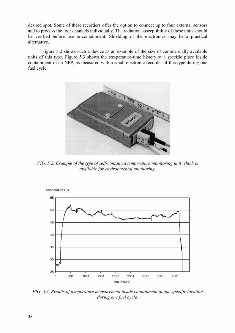
38
desired spot. Some of these recorders offer the option to connect up to four external sensors and to process the four channels individually. The radiation susceptibility of these units should be verified before use in-containment. Shielding of the electronics may be a practical alternative.
Figure 5.2 shows such a device as an example of the size of commercially available units of this type. Figure 5.3 shows the temperature-time history at a specific place inside containment of an NPP, as measured with a small electronic recorder of this type during one fuel cycle.
FIG. 5.2. Example of the type of self-contained temperature monitoring unit which is available for environmental monitoring.
5555
Temperature (C)
time (hours)
50
45
40
35
30
25501 1001 1501 2001 2501 3001 3501 40011
FIG. 5.3. Results of temperature measurement inside containment at one specific location during one fuel cycle.

39
Experience has also shown that the installation of simple mercury thermometers with minimum and maximum value storage also delivers practical and useful results for some types of NPP. In many cases this solution will be acceptable when the low price and the simplicity of these instruments are taken into consideration. One of the key areas in temperature monitoring is determining the location of hot spots along a cable run. Distributed temperature monitoring using fibre optic cable is a relatively new method that is starting to be evaluated for use in NPPs. Annex C1 discusses this technique in more detail.
5.2.3. Radiation monitoring The dose rate distribution in the plant can be measured with the aid of dosimeters installed at the most severe and other representative cable positions. In order to improve the validity of such measurements, it is recommended that the measurement period be extended to cover two operating cycles. The type of radiation dosimetry used for personnel purposes may not be appropriate for monitoring long term dose exposures to cables. Alanine dosimeters have proven to be particularly suitable for such long term measurements for the following reasons: (a) They are not significantly affected by temperature (0.2%/K). (b) Their fading at moderate temperatures is limited to 1% per year. (c) The influence of humidity can be overcome by hermetic sealing of the dosimeter. (d) The neutron dose to cable materials can generally be neglected during normal plant
operation. Dosimetry using alanine is well established and widely used. The method is based on radiation induced formation of stable radicals in alanine, using electron spin resonance (ESR) to measure the number of radicals present in the dosimeter [5.1]. Since radiation fields can be quite variable within a plant, dosimetry at the location of the cables is desirable. Annex C2 gives some examples of radiation monitoring programmes.
5.3. IDENTIFICATION OF LOCALIZED SEVERE ENVIRONMENTS (HOT SPOTS)
Adverse localized equipment environments include locations where temperature, radiation levels, chemical conditions, moisture and/or vibration are significantly more severe than the bulk conditions for the area. These are sometimes referred to as hot spots. Identification of such locations in a plant is an important aspect of cable ageing management, since these conditions are most likely to cause significant degradation within the lifetime of the plant. Four activities may be used to identify hot spot conditions. These are: interviews of plant personnel, review of operation and maintenance records, review of plant layout and equipment location drawings, and plant walkdowns. Each will provide a different perspective on the hot spot conditions that can lead to a full understanding of their significance for a particular plant.

40
Guidelines for the management of adverse localized environment conditions have recently been published [5.2]. The following sections provide a summary only of this publication; for further details and examples, please consult this publication.
5.3.1. Interviews of plant personnel
Frequently, hot spots have previously been identified by various groups. Interviewing plant maintenance, operations, health physics, and system-engineering personnel is a quick way to obtain hot spot information. These people are knowledgeable about the condition of equipment and plant areas, and can provide much of the information required. Plant design personnel should be able to identify those general areas and some specific areas where severe conditions would be expected. The interview of NPP operations, maintenance and technical staff is a quick way to obtain hot spot information on the basis of experience rather than analysis or hypothesis. Hot spots that have been remedied should also be identified. The interview process also helps to identify unusual effects of adverse environments that may not be obvious if the review is limited to radiation and thermal conditions alone. For example, the interview process for one plant identified reactor instrumentation cables that were susceptible to a combined thermal, radiation and humidity condition. Rather than hardening of the polymers, the result was swelling of the cable jacket that prevented proper installation of connector backshells when the connectors had to be replaced. Continuous feedback of information from maintenance personnel concerning observations of cables during routine tasks is important for early problem identification. Under this approach, maintenance personnel are trained to identify degraded cables and report their findings to a cable system engineer for evaluation and corrective action. The cable system engineer is responsible for determining appropriate actions such as further inspections, changes to the cable type, and rerouting. This continuous feedback method will identify many conditions before the overall cable system degrades significantly.
5.3.2. Review of operating and maintenance experience
Corrective action programmes exist in many power plants. These programmes are used to track plant resolution of identified problems including equipment failures and damage from adverse environmental conditions. The events that have occurred are often summarized in databases that may be searched electronically or manually to identify cases where adverse conditions exist that could affect cables. Other databases related to maintenance and operations may exist and in some cases databases related to multiple plants exist (e.g., NPRDS) that may provide insights and information.
5.3.3. Review of plant layout
Review of plant layout drawings can also be used to identify locations of equipment that generate conditions such as significant temperatures, and/or high levels of radiation, vibration or adverse chemical environments. The review of the drawings allows the determination of the areas expected to be benign and to have a very low likelihood of a hot spot and those areas that should be reviewed further. The areas with the potential for hot spot conditions can be reviewed in more detail to determine if there are susceptible cables and equipment in them. The review can also indicate areas that should be given priority for specific inspections or general walkdowns to confirm or disprove the existence of hot spots.

41
5.3.4. Walkdowns Walkdowns of the plant can be performed to identify areas with adverse conditions. The scope of a walkdown can range from evaluating the entire cable system on an area by area basis to very focused evaluation of specific areas. These walkdowns can serve to identify such conditions as environmentally induced damage to cables and equipment, damage to thermal insulation on hot pipes and vessels that would make hot spots more severe, and the location of cables in adverse environments. The walkdowns can be integrated into normal activities of plant personnel or can be performed on a formal basis for specific plant. For a formal walkdown effort, plant floor plans would be obtained and the areas reduced to manageable sizes to be inspected and evaluated. If hot spots are identified, specific data concerning the environment can be obtained by such techniques as thermal data loggers and radiation surveys and monitoring. Hot spots would only be of interest if cables important to safety or plant operations were located in the vicinity. Walkdowns may also identify other adverse conditions such as improper installation of cables (e.g., cable lying across sharp metal edges) or obvious physical damage that should be corrected to assure the overall adequacy of the cable system. Indications of hot spot locations may be obtained by evaluation of cable surfaces; for example, the observations listed below would be useful indicators: (a) discolouration of jacket (b) blooming or weeping of plasticizer (c) powdering of surface (d) cracking or crazing of jackets. Indication of hot spot conditions may also be observed from the cable environs. Scorched or deteriorated paint or wall coatings are indicative of adverse thermal or radiation environments. Accumulation of borates or other chemicals observed on or around cables should be evaluated. Walkdowns in containment may or may not be a practical method for evaluating cable depending on the layout and design of the cable system. If the cables are located in conduits, inspection may only be possible at terminations and in junction boxes. Inspections may be time consuming in such cases, because junction and termination boxes will have to be located and opened. Integration of such evaluations into normal work practices may be the most practical means of implementing such inspections. Where cables are located in trays, walkdowns may be easier to implement. If inspections are integrated into normal work practices, cable sections that are not evaluated by normal efforts (such as penetration terminations) should be evaluated by specific walkdowns. The goal of the walkdown is to identify indications of damage or severe environmental conditions. The indication of high stress environment may be through signs such as discoloured paints or chemical deposits in the vicinity of the cable. This is discussed further in Section 6.4.1.
5.3.5. Typical hot spots in various NPP designs
Some examples of generic hot spot areas and environmental monitoring levels associated with the areas are shown in Table 5.1.

42
5.4. IDENTIFICATION OF WORST CASE CABLES
The process for identifying those cables which are most likely to be of concern is illustrated in Fig. 5.1. The evaluation falls into several stages, each of which will tend to reduce the number of cables that need to be evaluated further. At the end of the process, all of the cables included in the evaluation will have been prioritized in terms of the need for supplementary ageing management activities. TABLE 5.1. TYPICAL HOT SPOT AREAS IN NPPs
Reactor type Hot spot location Temperature Radiation dose rate
PWR Steam generator box 47–48°C (max. 100°C)
0.1 Gy/h
Primary loop 50°C 0.7 Gy/h
BWR Drywell neck region 100 ± 5°C 0.5 Gy/h
Primary steam relief valve region
70 ± 5°C 0.01 Gy/h
Power range monitor region
80 ± 5°C 0.24 Gy/h
CANDU
(Ontario Power Generation plants)
Feeder cabinet and reactor vault Boiler areas
41–60°C
30–60°C
0.6–2.1 Gy/h
0.008–0.2 Gy/h
The first stage is to identify the type of circuit that each cable serves. In terms of the scope of this report, all safety important I&C cables within containment would go through to the next stage of the evaluation. All other cables would be assigned a low priority for ageing management. Utilities might also choose to include in the next stage cables which are operationally important. The second stage of the process is to identify the normal operating conditions of the cable within the lifetime of the plant, including accident conditions. This stage would need to include the normal environmental conditions (i.e. temperature, radiation) at the cable locations using methods such as those described in Section 5.2, and the location of known hot spots (Section 5.3). It would utilize measured values of the environmental conditions, where available; in their absence, design values would need to be used. Having identified the operating conditions, the third stage is to assess their impact on the ageing behaviour of the cable materials. This stage would utilize the following types of existing information.

43
• feedback from operational experience, from plant personnel and records, • prediction of expected ageing effects using Arrhenius analysis, predictive methods for
radiation ageing and available accelerated test data. The cables are then assigned to one of three priority categories, depending on the results of the preliminary evaluation. • high priority — safety important cables where the environmental conditions are likely to
cause severe ageing during the plant lifetime, • medium priority — safety important cables where the environmental conditions are
likely to cause moderate ageing during the plant lifetime, • low priority — safety important cables where the environmental conditions are likely to
cause minimal ageing during the plant lifetime, and all other cables not important to safety.
It would be expected that all cables in the high priority category would be subjected to further ageing management activities, such as condition monitoring (see Section 6) or planned replacement. The evaluation process can be refined as additional information becomes available from supplementary ageing management activities. For example, if condition monitoring of high priority cables within the plant indicates that degradation is less severe than predicted, it may be possible to move some cables into a lower priority category and discontinue condition monitoring on those cables. Similarly, if more detailed predictive modelling information becomes available which indicates that more severe degradation would occur, then some cables may need to be moved into a higher priority category. An example of a preliminary evaluation of this type, which covered all cables in a US NPP, is given in Ref. [5.3]. For this plant, thermal ageing of the cables was the main concern, radiation effects being found to be negligible. Reference [5.3] describes a project that evaluated the ability of over 53 000 cables to perform their design function throughout a 60 year period of normal plant operation. The programme is summarized below. The goals of the cable ageing management programme were to reduce maintenance and replacement costs, maintain the reliability of electrical cables and to assess the impact that cable ageing issues have on license renewal. The programme was conducted in three phases: data collection, life cycle management, and licence renewal. The project team separated the cables into two groups, those that had to be environmentally qualified (EQ), and those that did not require EQ. The project team analysed plant environments, operating requirements, loads, and cable insulation materials. They also evaluated various condition monitoring (CM) techniques for use in assessing ongoing ageing. The initial analysis, based on design basis environmental conditions, showed that most of the non-EQ cables had a 40-year thermal life. The design basis conditions contained conservative assumptions on the temperature within the plant. A re-evaluation using less conservative assumptions, more appropriate to actual conditions in the plant, showed that most cables had a calculated life of at least 60 years for thermal ageing. For most of the EQ cables, a 60-year qualified life had been demonstrated during the initial EQ testing

44
programme. The overall assessment was that benign service conditions existed for most of the cables within this particular plant. The evaluation identified those cables which could be placed in a condition monitoring programme (see Section 6). If condition monitoring indicated severe degradation in these worst case cables, additional cables in slightly less severe environmental conditions could be added to the scope of the supplementary programme.
REFERENCES TO SECTION 5
[5.1] AMERICAN SOCIETY FOR THE TESTING OF MATERIALS, Practice for the use of alanine/ESR dosimetry system, Rep. ASTM 1607-94, ASTM, Philadelphia (1994).
[5.2] ELECTRIC POWER RESEARCH INSTITUTE, WEINACHT, R., Guideline for the management of adverse localized equipment environments, Rep. EPRI TR-109619, Palo Alto CA (1999).
[5.3] ELECTRIC POWER RESEARCH INSTITUTE, Cable ageing management programme for D C Cook nuclear plants Units 1 and 2, Rep. EPRI TR-106687, Palo Alto, CA (1996).
45
6. CONDITION MONITORING
Condition monitoring (CM) refers to activities performed to assess the functional capability/operational readiness of equipment [6.1]. CM provides information on the status of the cable in terms of the value of a condition monitoring parameter, hereafter called a condition indicator (CI), which is representative of the degree of degradation of the cable materials. Effective monitoring of ageing degradation requires knowledge of one or more condition indicators which indicate the physical state of the cable at the time of observation. CM may identify ageing mechanisms that may not have been adequately addressed during original qualification; it can also identify incipient failures. CM can be a valuable adjunct to initial environmental qualification (EQ) — see Section 4. CM can be used to verify the qualified condition and qualified life, assess the remaining service life of the cable, and possibly revise the qualified life. For a CM technique to be of practical use for installed cables, it also needs to be non-destructive or essentially non-destructive (e.g. by taking microsamples of a few mg of material). Where deposits of cable samples are available, or where cable samples are replaced with new cable, non-destructive tests are not essential. This section of the report reviews possible condition indicators and puts forward practical recommendations for sampling. Each individual CM technique will then be reviewed, together with its pros and cons, and finally, the possibility of correlating CM with DBE survivability will be discussed.
6.1. CONDITIONS INDICATORS
All condition monitoring techniques are aimed at ensuring the operability of cables. The operability is mainly guaranteed by maintaining the most important electrical parameters (such as insulation resistance, leakage current, breakdown voltage, etc.) Electrical engineers are therefore mainly focused on surveying electrical parameters. However, practical experience with most cable types has demonstrated that electrical parameters are normally not representative of cable insulation and jacket ageing; electrical failure usually follows after mechanical degradation. Therefore, international practice is to monitor mechanical or chemical parameters of cable insulation/jacket materials to assess ageing. In addition, as will be discussed under Section 6.5, electrical indicators are required to assess DBE survivability. A condition indicator (CI) which shows a trend where the indicated degradation is insignificant for a long period and then rapidly decreases to an unsatisfactory level is not suitable for assessing the degree of ageing. An appropriate CI is keyed to detecting changes caused by significant ageing mechanisms and provides a warning of impending functional degradation that may not otherwise be apparent. Ideally, monitoring a single Ci would be sufficient to determine the cable’s qualification status. Even more ideally, it would be possible to rely on one single CI for all cable types. As will be shown, in reality there is not a single CI that can be used for all types of cable insulating material.
6.1.1. Electrical parameters
As mentioned in the introduction to this section, the change in electrical properties such as insulation resistance, leakage current, loss factor, permittivity, or breakdown voltage,

46
are not generally representative of the ageing of the insulation material and cannot be used as condition indicators at present for most cable types. Some electrical parameters, such as dielectric loss, show promise as condition indicators but this is an area that is still under investigation and is not currently at a stage of practical application, with the possible exception of insulation resistance measurements in PVC insulated cables. Electrical parameters can usually be measured on the given cable, provided that both ends are accessible and that the cable can be de-energized.
6.1.2. Visual aspects
A colour change of the cable jacket is usually an indicator that something has changed in the chemical structure or composition of the insulating material. For different materials, the colour change can be either discolouration or darkening. Black rubber cables can change to grayish-white. Even for a given material, the intensity of the colour change cannot be correlated to the amount of degradation. Therefore, the colour change can only be used as a preliminary indicator, of the need for further enquiry. Sometimes the insulation of a wire or the jacket of a cable may show crazing on its surface. This indicates a severe deterioration of the cable and is an indicator of failure. For some materials, the cable jacket may exude an oily substance. This indicates a loss of some additive (such as plasticizer in PVC) and hence a significant degradation of the material. Swelling of the cable may indicate that it has absorbed moisture, hence its dielectric properties may no longer be guaranteed. The main advantage of visual aspects as a condition indicator is that they do not require sampling or measuring equipment and can easily be incorporated into walkdowns and normal maintenance procedures.
6.1.3. Chemical properties
Because ageing always results in modification of the physico-chemical structure and/or composition of the material, ageing can be monitored using a CI related to the material’s properties at the molecular level. Measurements of the molecular weight, the gel fraction, the degree of unsaturation, or the crystallinity of the polymer are powerful means of understanding its ageing mechanisms. Measurements of the content of protective agents (such as anti-oxidants) and plasticizers are also a good means of following the ageing of the compound. Usually these chemical parameters are not easy to measure, and one needs a baseline to be able to correlate the results within the degree of ageing and remaining capability of the compound. Most of the chemical properties mentioned can usually be measured from microsamples.
6.1.4. Mechanical properties
The tensile elongation at break is usually accepted internationally as a good reference to assess the degradation of the insulating material(s) of a cable [6.2]. It may reasonably be used to assess the degree of ageing of the cable. Whether it can be used to assess the remaining operability of the cable is still an open question for some materials. Hardness and

47
compressive-modulus characteristics of the complete cable are also a good indicator of ageing in some cable materials (this is used in indenter measurements). Some methods are still under development to try to correlate the torque modulus of a complete cable with its ageing.
6.2. SAMPLING METHODS
Having decided on the condition indicator which is the most appropriate for the cable materials of concern and on the cable type to be evaluated (as described in Section 4), the next aspect to be considered is the approach to sampling. Practical considerations of access, such as those described in Section 6.2.4 and in the practical experience described in Appendices D.1 and D.2, need to be taken into account, and this will influence the CI to be chosen. Also a basic decision needs to be taken as to whether the cables to be tested are installed cables which are in use in the NPP or whether there are ‘sacrificial’ cables, which are not part of functioning circuits, that could be used. In the latter situation, cables which are no longer in use or which form part of a deposit of cable samples installed specifically for monitoring can be used for testing purposes.
6.2.1. Cable deposits
Where deposits of cable samples have been installed in an NPP, these generally provide access for condition monitoring with the least requirement for disturbance to operations. However, very few NPPs have such deposits in place. Cable deposits are normally installed in hot spot areas within the plant, where the radiation and/or thermal environment is more severe than for the bulk of the installed cables. There is often only a limited quantity of material available in the deposit for testing, so it is important that samples for any destructive tests (e.g. elongation measurements) are conserved as much as possible. For this reason, non-destructive methods (such as indenter measurements or OIT/OITP), which are known to correlate well with changes in elongation , can be used initially to conserve material, if necessary. When there are indications of significant degradation in the mechanical properties, the first samples can be removed for destructive tests.
6.2.2. Real time aged cables
Any condition monitoring or sampling of installed cables which form part of functional circuits will entail some disruption to operations. Formal documentation will be required and it will be necessary to demonstrate that any CM test being used does not affect the long term functionality of the cable. Section 6.2.4. highlights some of the practical difficulties involved.
6.2.3. Microsampling methods
At present it is not easy to get permission from NPP operations staff for microsampling of cables for CM methods such as OIT/OITP in some countries (e.g. in USA). This is mainly due to concerns about the sampling introducing physical damage (such as cuts) which could affect the electrical properties of the cable. Sampling is usually accepted on cable

48
jackets, but taking samples from the insulations can usually only be performed at cable ends. Otherwise, repairing techniques have to be defined and accepted by the operators. A programme at EPRI is currently in place to establish acceptable microsampling test methods [6.3].
6.2.4. Precautions during in situ measurements and/or sampling
Planning is important for sampling and/or testing to be performed in a reasonable time period and at reasonable cost. The cables to be sampled must be determined and then their routing must be evaluated to determine where sampling can be performed. Cable trays and junction boxes are often located inconveniently near ceilings or hidden from sight. Trying to locate test positions can take more than 50% of the sampling/test time. In addition, the test equipment needs to be self-powered because locating power outlets and obtaining extension cords in a power plant can consume large amounts of time. When trying to perform CM tests, identification of individual circuits at other than the terminations can be extremely difficult, especially in older plants where cables may have no identifying markings even as to type and manufacturer. In trays with anything more than a few cables, finding a specific cable is generally not possible. Often there are 50 or more cables of the same type and configuration. Therefore, one may have to sample/test a representative set of cables of the same construction and manufacture as that of the cable circuit that is to be tested. Generally, the only place where a specific cable circuit can be identified is at a termination to an end device. In addition, only at the end device does one have access to the insulation. Elsewhere, only the overall jacket is exposed, making direct insulation evaluation impractical. When sampling/testing cables, wipes are need to clean surfaces (health physics personnel may be needed to verify that loose contamination levels are not severe). In addition, the sample/tester must have a means of covering test equipment to prevent permanent contamination when it is used in radiologically controlled areas. Equipment becomes difficult to carry and operate when covered with plastic and tape. Testers should be prepared for working in places with low or difficult accessibility, sometimes in tight spaces. The vertical distance between trays may be as little as 20 cm causing work to be at arms’ length. Junction boxes may be 25 cm square or even smaller, leaving little space for applying tests to cable surfaces and little length to take samples. Flashlights will be needed for work in dark areas. Staging for testing may also require a significant amount of effort. Often the location of the cables to be tested requires the use of ladders or scaffolds. Having scaffolding erected may require considerable effort and time. In addition, modern plant practice may require the use of harnesses for fall protection and training in their use, further increasing preparation time and discomfort for the tester. A further consideration during testing includes the state of energization of the cable. in principle, the indenter does not penetrate jackets or insulations and can be used with low voltage circuits energized. However, other sampling methods may require de-energization. De-energization greatly impedes testing of cables in trays where the state of energization of a cable would be difficult to ascertain. In some cases, the operator may not allow sampling/testing of some particular cable, e.g. where a break or a short-circuit could cause loss of the equipment, causing a safety system operability problem. While sampling/testing of energized low voltage cable is usually possible with most of the CM techniques, care is

49
necessary at terminations where exposed conductors and buses are near the test area. Use of insulating gloves may be desirable in such situations. Testing of medium and high voltage cable while energized is not recommended without strong precautions.
6.3. AVAILABLE CM METHODS
A wide range of CM techniques have been evaluated over the last few years and there is still considerable development work which is ongoing [6.4–6.8]. This is still a developing area but there are a number of techniques which are already of practical use and are being used in plants. Reference [6.7] provides a summary of most of the techniques which have been evaluated in recent years. Most of the currently available CM methods give information on the state of degradation of the cable material only at the position measured, and do not give direct data on adjacent areas. Measurements at intervals along a cable will give some information on general trends but will not identify a highly localized area of degradation. Most methods are also limited to the accessible parts of the cable (see Section 6.3.4). In practice this means that the cable jacket can be measured (where the cable lies in cable trays) and the insulation can only be measured at terminations or junction boxes, unless sacrificial samples are available. The most widely used methods at present are indenter measurements and thermal analysis of microsamples, using oxidation induction time (OIT) or temperature (OITP) measurements. There is currently no single CM method which is suitable for all cable materials. Indenter measurements are probably the most widely applicable, but are not suitable for materials like XLPE. The other widely used technique (OIT/OITP) in contrast, works best with XLPE and similar materials. Some of the limitations of specific CM methods are detailed together with their description in the following sections. More recently, measurements based on photo-acoustic spectroscopy are showing some promise [6.8]. This is currently at the laboratory evaluation stage and work is continuing to develop suitable sensors to enable the technique to be applied directly to cables. Table 6.1 summarizes the main characteristics of the available CM methods. They are discussed further in Sections 6.3.1 to 6.3.7.
6.3.1. Visual/tactile inspection
Although not a quantifiable method for condition monitoring, visual/tactile inspection of cables can be a very useful and practical adjunct to any cable ageing management programme. As part of normal maintenance activities, it can be used to detect the absence or presence of severe deterioration, it can identify significant ageing (e.g. hardening, cracking, crazing), damage from cutting or chafing, or contamination of cable materials. When ageing is detected by visual inspections, decisions can be made concerning the application of more sophisticated CM techniques to more precisely define the extent of ageing. Application of sophisticated CM techniques to all cables in a system is cost prohibitive. However, when testing a limited set of cables, the surrounding cables can be visually and tactilely inspected. Such inspections will provide further insight regarding the general condition of the surrounding cables and may lead the tester to widen the scope of evaluation if unexpected conditions are identified. The results of the visual/tactile inspection

50

51
strengthen the findings from the application of the more sophisticated CM tests and provide a broader perspective of the condition of the cable system as a whole.
Guidelines for visual inspections of cable by plant maintenance personnel have been developed by a number of organizations [e.g. Ref. 6.9]. These give examples of the types of effects that should be looked for and methods for systematic inspections.
The most relevant signs of degradation have been described in Section 6.1.2. In addition, one may look for ionic deposits (white or greenish powder). Tactile inspection consists of gentle manipulation of the cable (torsion or bending, but it should not be bent over the permissible bending radius), looking for a change of colour (usually discoloration) at the place of bending, looking for the appearance of cracks (on the outer jacket), and listening for any cracking noise (from the inner insulation).
6.3.2. Indenter measurements
Indenter measurements provide an indication of the compressive modulus of the cable material under controlled conditions. A probe tip, based on the ASTM hardness probe, is driven into the surface of the cable material and the load-displacement curve is measured. The slope of the curve is taken as an indenter modulus (IM) value.
The IM values obtained are dependent on the test parameters used — the probe speed, the force range used for analysis of the slope, and in some materials, the test temperature. Provided that standardized test parameters are used, IM values show a good correlation with ageing degradation in most of the cable materials commonly used in NPPs. The main exception is XLPE, where changes in IM are small until severe degradation is present. The main restrictions to this CM method are: (a) it does not show a good correlation with ageing degradation in radiation aged PVC and
for XLPE, IM values stay quite constant over a long period and then rapidly increase at high degradation levels;
(b) the cable construction can influence the result, particularly in cables with a loose construction or with significant variations of thickness of jacket or insulation material. If present, an inner metallic shielding may influence the result obtained;
(c) the indenter only measures the jacket behaviour (except in junction boxes) and correlation with insulation properties is required;
(d) the temperature during measurement affects the value obtained for some materials which may need a temperature correction factor;
(e) it requires correlation with elongation at break. The benefits from this method are: (a) easy in situ application (b) it allows quick screening (in conjunction with visual inspection) (c) results are obtained immediately on the spot. Portable indenter instruments, suitable for use in plant, are available commercially. Practical experience with indenter measurements has been gained in some NPPs. Some examples of this experience are described in Annex C.3 for evaluation of hot spots and in Annex D.1 for experience in Canadian NPPs.

52
If indenter data are to be made available to other users, it is important that information on the test procedure used be reported, in addition to the test results. For direct comparison of data, the following additional information should be included in the test report. • Test temperature • Probe speed • Force range used for analysis (it would be helpful to establish standard ranges for
materials commonly used in cables) • Calibration procedure (it would be helpful to have standard samples available for
calibration purposes).
6.3.3. OIT/OITP measurements
OIT and OITP measurements are mainly linked to the level of anti-oxidants present in the material. These measurements use standard thermal analysis equipment (DSC) to measure the onset of oxidation of a microsample exposed to flowing oxygen, either at a constant temperature (OIT) or during a temperature ramp (OITP). The onset time (OIT) or onset temperature (OITP) shows a good correlation with ageing degradation in some cable materials. It has been known for a long time that the effectiveness of the antioxidant depends on the temperature [6.10]. For reproducible results, it is important for the test method for OIT and OITP to be standardized. Some of the factors that need to be considered are sample size and form, sample pan material, oxygen flow rate, stablization time in nitrogen before admitting oxygen (OIT), test temperature (OIT) and temperature ramp rate (OITP) [6.10–6.13]. An ASTM standard exists for polyolefins [6.14]. To date, the following recommendation can be given for any material: before starting an OIT measuring campaign, the most appropriate test temperature must be determined for each type of material. This would preferably be investigated in the laboratory by correlating the OIT results with values of the elongation at break after ageing at low dose rate. An example of correlation between OIT (by DSC) and elongation at break is shown in Annex D.2. OIT is particularly useful for materials like XLPE and PE, for which no confident results can be obtained from indenter or elongation measurements. For other materials, applications have been reported but special knowledge about the material composition and its ageing mechanisms is required. The main restrictions related to these methods are:
(a) the method is only applicable to materials containing anti-oxidants (b) the methods are not easily applicable to PVC materials but can be used with special
precautions (c) microsamples are usually taken from the surface of the cable jacket, which may not be
representative of the state of the bulk material (d) contamination may be a restriction for sampling; the use of a chemical decontaminant
must be avoided to avoid altering the surface (e) correlation from jacket to insulation does not seem possible

53
(f) requires correlation with the elongation at break [6.15] or with other properties reflecting cable functionality.
The main advantages of the methods are: (a) in situ microsampling is usually possible (b) almost non-destructive sampling. Practical experience with OIT/OITP and DSC measurements has been gained in some NPPs. In particular, practical details are given in references [6.16] and [6.17] as well as in Annex D.2. Predictions of residual lifetime based on OIT/OITP measurements can also be done in some cases [6.17, 6.18]. An analytical method is proposed in Annex D.3. If OIT/OITP data are to be made available to other users, it is important that information on the test procedure used is reported, in addition to the test results. For direct comparison of data, the following additional information should be included in the test report. OIT tests: • Type of instrument used • Method of calibration • Sample weight and preparation method • Type of sample pan (whether open or closed) • Oxygen flow rate used • Temperature profile used to reach oxidation temperature • Method of establishing baseline (a raw data plot would be helpful) • Method of establishing oxidation onset. OITP tests: • Type of instrument used • Method of calibration • Sample weight and preparation method • Type of sample pan (whether open or closed) • Oxygen flow rate used • Temperature ramp rate and starting temperature • Method of establishing baseline (a raw data plot would be helpful) • Method of establishing oxidation onset.
6.3.4. Thermo-gravimetry analysis (TGA)
This method monitors the weight loss of a sample when heated at a constant temperature ramp rate. It is representative of the content of volatile molecules and is mainly suitable for PVC materials that lose their plasticizers. A detailed explanation of TGA practice is described in Annex D.4. There are standards available for TGA testing [6.19, 6.20].

54
The test should be carried out at a constant temperature ramp rate, in a given atmosphere (usually oxygen, but nitrogen can also be used). The maximum temperature in the TGA test only needs to be high enough to determine the onset value. Sample preparation for TGA tests is the same as that used for OIT tests. Hence, the restrictions and advantages concerning the sampling for both methods are the same. If TGA data are to be made available to other users, it is important that information on the test procedure used is reported, in addition to the test results. For direct comparison of data, the following additional information should be included in the test report. • Type of instrument used • Method of calibration • Sample weight and preparation method • Type of sample pan (whether open or closed) • Oxygen flow rate used • Temperature ramp rate and starting temperature • Method of establishing oxidation onset.
6.3.5. Other physico-chemical methods
Torque measurements were made at JAERI [6.8] and were included in the round-robin test [6.21] for comparison with other techniques. The torque tester uses lengths of whole cables which are gripped in a pair of chucks separated by a given distance. One end of the cable is fixed and the other is twisted by a given angle at a constant frequency. The recorded torque value is related to the stiffness of the cable; for most cables, there is an increase in torque with ageing. The initial torque measured is a function of both the material properties and the construction of the cable. The method is probably also temperature dependent. Like the indenter method, the torque measurements can be done in situ without sampling. Work on this technique has been discontinued due to the risk of possible cable damage during in situ testing. Density measurements on microsamples taken from the surface of cables have also shown some potential as a CM method. For most cable materials, the density increases with increasing degradation and can be measured with simple laboratory equipment, such as a density gradient column or microbalance [6.22]. FTIR (Fourier transform infrared spectroscopy), chemi-luminescence and photo-acoustic spectroscopy have also been tried, but so far have been limited to laboratory studies. Microcalorimetry, measuring the heat dissipation (exothermal) and heat absorption (endothermal) as a result of chemical and physical processes in the material, has been used in laboratory studies with promising results [6.4]. It has the advantage that it can also be used to measure the activation energy at normal service temperatures.
6.3.6. Elongation measurements
For many years, the procedures for determining the effects of ionizing radiation on insulating materials have been clearly described in IEC Standard 544 [6.2]. This standard
55
recommends basing the radiation tests on mechanical tests. Practical details to carry out the tensile tests and to measure the elongation at break of polymeric samples are given in several international standards [6.23–6.25]. Over many years, 50% absolute elongation has been considered as a practical and safe limit as a failure criterion. This criterion was based on the fact that if a single wire is coiled around itself, the maximum elongation undergone by its insulation is 50% absolute. Experience has demonstrated that cables with a residual elongation of their insulation and jacket >50% absolute can still fulfil their required functions under normal operation. However, long term studies have shown that some materials (mainly PVCs) may show a strong degradation of their electrical properties, and fail the DBE test, even with residual elongation well above 50% absolute. In contrast, experience has shown that some cables with a residual elongation of their insulation as low as a few percentage points can still pass a DBE test [6.26]. It is recognized that the 50% absolute elongation criterion is not necessarily fully representative of the material degradation. To reach this value, a material with an initial elongation of 500% absolute is more degraded than one starting with 100% absolute The IEC Standard 544 recommends using 50% of initial value as an end point criterion [6.2]. It is therefore recommended to use available experience about a specific material to judge which of either the 50% absolute or the 50% relative is the best criterion.
The main benefits of elongation measurements are:
(a) elongation-at-break measurements based on tensile tests are internationally standardized.
(b) elongation-at-break is generally a good condition indicator. It decreases gradually with the amount of induced degradation for most polymeric materials, this degradation being either thermally or radiation induced. This is the reason why most CM techniques mentioned here have been correlated to elongation-at-break measurements. An example of the reduction of elongation with simulated service ageing is shown in Annex D.2.
The main limitations to elongation measurements are:
(a) Tensile tests require quite large samples. Sampling is destructive from the viewpoint of the cable. Sampling may not be destructive from the viewpoint of the NPP if a cable deposit is available or cable replacement has been planned.
(b) For cross-linked polyolefins, elongation-at-break is not a good condition indicator because it stays quite constant over a long period and then rapidly decreases to an unsatisfactory level.
(c) Elongation-at-break measurements may not be possible, or not be representative, if the material consists of a composite (two inseparable layers).
If elongation data are to be made available to other users, it is important that information on the test procedure used is reported, in addition to the test results. For direct comparison of data, the following additional information should be included in the test report: • Type of test machine used • Calibration procedure • Method of gripping samples and type of grip face

56
• Test temperature (particularly if outside the range 20–25°C) • Cross-head speed • Method of measuring elongation.
6.3.7. Reproducibility of CM measurements
The reproducibility of a range of the more commonly used CM methods has recently been assessed in a series of round-robin tests [6.21]. These tests were carried out on a wide range of cable materials (15 insulations and 15 jackets, made out of PVC, PE, XLPE, CSPE, EPR, EPDM, SiR, and EVA) from different countries as part of the IAEA co-ordinated research project. Unaged materials and samples that had been thermally aged were sent out to 12 institutes or companies participating in the CRP. Each of the participants tested the samples according to the technique(s) usually in use in their laboratory. The methods that were included in the round-robin tests were: (a) Elongation at break (b) Indenter modulus (c) OIT and OITP (d) Thermo-gravimetric analysis (TGA) The most robust of the non-destructive (or essentially non-destructive) CM methods examined was indenter modulus. Once allowance had been made for temperature variations between the laboratories, variability of the order 5% to 10% was typical for most materials. Some cables, particularly the harder PVC materials and those cables with a loose structure, showed somewhat higher variability. The main conclusion to come out of the round-robin tests was that if international comparison of CM data is envisaged, then more detailed standardization of CM test methods is needed. Annex D.9 contains the CRP report on the round-robin tests reprinted from reference [6.21], which includes information on cable samples and materials used, test results, variability between laboratories of test procedures and recommendations for reducing it, and gives specific recommendations as to the test parameters that need to be reported for each CM method. The participants agree that international comparison of CM data is not essential; each plant operator may apply his own method and compare the results with his own reference data. However, it would then be necessary for each plant to generate their own baseline data. Working Group 15E of the International Electrotechnical Commission is currently preparing a document with recommendations for some of the more common CM methods [Part 5 of Ref. 6.2 is in preparation].
6.3.8. Recommended CM methods for cable materials
There is enough information available on the most developed of the CM methods for some preliminary recommendations to be made on the most suitable test methods for different types of cable material. The table below gives a brief summary of the applicability of the most developed methods.

57
CM method XLPE CSPE EPR/EPDM PVC EVA
Visual/tactile inspection
Tensile tests X
Indenter X
OIT/OITP X ( )
TGA X X X X – CM method shows a reasonable correlation with ageing.
( ) – CM method shows reasonable correlation with ageing, but care is needed to avoid damage to the test equipment from degradation products.
X – CM method does not show good correlation with ageing.
6.4. CORRELATION BETWEEN JACKET AND INSULATION DEGRADATIONS
For all of the currently available CM methods that are in use in NPPs, measurements are limited to those parts of the cable that are directly accessible. In practice this means that the cable insulation material can only be measured at terminations and junction boxes, unless repairing techniques are defined and allowed or samples are available from a suitable deposit or unused circuit. For the main cable run, only the jacket material may be accessible for CM measurements, provided that the cable is not installed in a conduit. However, since the functionality of the cable is determined by the condition of the insulation, it is important to know whether there is any correlation between the degradation of the jacket and the degradation of the insulation in practical cables. If there is some correlation, it may be possible to use the jacket properties as an indicator of the insulation condition. In general, the insulation and jacket are of different materials and it is expected that their rates of degradation would be different. However, for some material combinations, there is a correlation between the ageing rates of jacket and insulation, or the jacket can provide an indication of the insulation conditions. Some examples taken from real ageing of various cables are given in Appendices D.5, D.6 and D.7. They confirm that from one cable to another, and from one ageing environment (e.g. thermal) to another (e.g. radiation), correlation between insulation and jacket materials is only occasionally observed. In addition, when assessing degradation for a complete cable, chemical interactions between the insulation and jacket materials must be considered (see Section 3.2.5).
6.5. CORRELATION OF CM WITH DBE SURVIVABILITY
The first aim of any CM technique is to provide information on the status of the cable and on its degree of degradation. From this, and in comparison with the qualification data, it should be possible to assess the remaining lifetime. The CM programme also seeks to answer the question as to whether the cables monitored are in a condition to survive the additional stress that is introduced during and after a DBE. With regard to environmental qualification, DBE survivability means that a component is able to perform its function satisfactorily through the end of the DBE including the required post-DBE period. As this event has not taken place at the time of measuring the selected condition indicator, this additional stress must be considered in a suitable way. In general, DBE failures only occur after the cable material has become severely embrittled. There are some exceptions to this, particularly for

58
PVC cables, where degradation of electrical properties during a DBE are significant in cables which retain significant flexibility. At present, few systematic studies have been carried out to correlate the values given by the CI and the ability of a cable to survive a DBE, and no appropriate acceptance or failure criteria have been identified. Therefore, a master curve (or lifetime curve) must be determined to correlate the selected CI prior to the DBE to cable functionality during and after the DBE. This section does not give guidance on DBE testing, nor the DBE sequence or the parameters to be measured. It gives specific guidance on the way to draw a master curve (or lifetime curve). The proposed method is the following: (a) Selection of an appropriate CI and related CM technique (see Sections 6.1 and 6.2). (b) Artificial pre-ageing in the laboratory with respect to the most important constraints
(usually temperature and radiation). This ageing campaign is divided into steps simulating for example 5 year periods, and it must take into account the recommended accelerating factors, as discussed in Section 3 of this report.
(c) At each time interval, the selected CI are measured, then the DBE sequence is conducted and the CI are again recorded (during or after the DBE sequence).
(d) Both values prior to and after the DBE sequence are plotted as function of time (Fig. 6.1).
After ageing in operation, measurements of the selected CI can be made either in situ, or
on sacrificial cables, or on cables from the deposit or from sampling. The measured value of the CI is then compared to the master curve. From this comparison, it is possible to determine whether the simulation has been well done (in particular the accelerating factors). If the simulation has been close to reality, then the point should fit on the exact co-ordinates (CI-value and time) of the curve. If the simulation has been too optimistic, the point will correspond to a longer time on the master (lifetime) curve, and the remaining lifetime will have to be shortened. If the simulation has been too conservative, the point will correspond to a shorter time on the curve and the remaining lifetime can be extended.
120
CI prior to DBE
limit of acceptance
CI after DBE
Con
ditio
n In
dica
tor (
%)
Simulated time (years)
100
80
60
40
20
00 10 20 30 40 50
FIG. 6.1. Variation with simulated time of the condition indicator (in % of initial value), measured prior to and after the DBE sequence.

59
When the CI-value (measured on the real time aged cable prior to DBE sequence) approaches the limit of acceptance, the operator may decide to perform further tests, such as a full DBE test on a complete cable, or to replace the cables altogether. The results of a study of correlation of CM methods with DBE survivability on cables used in Swedish NPPs are reported in Ref. [6.4]. An example of correlation between indenter modulus and DBE survivability for CSPE cables is given in Annex D8. Cable specimens artificially aged to different degradation levels, as defined by different values of the selected condition indicator (in this case, indenter modulus), are subjected to the DBE test during which the insulation resistance is measured. A reasonable correlation between these two parameters is found. Correlation of CM methods with DBE survivability was one of the objectives of the 2nd CRP which has not been fully achieved. There have been only a limited number of such studies reported in the open literature and there is still a need for further work in this critical area.
REFERENCES TO SECTION 6
[6.1] INTERNATIONAL ATOMIC ENERGY AGENCY Safety Report Series No. 3, Equipment Qualification in Operational Nuclear Power Plants: Upgrading, Preserving and Reviewing, IAEA, Vienna (1998).
[6.2] INTERNATIONAL ELECTROTECHNICAL COMMISSION, “Guide for determining the effects of ionizing radiation on insulating materials”, Part 1: Radiation interaction, Rep. IEC 544-1 (1977), Part 2: Procedures and test for irradiation, Rep. IEC 544-2 (1991), Part 4: Classification for service in radiation environment, Rep. IEC 544-4 (1985), Part 5: Procedures for assessment of ageing in service (in preparation), Rep. IEC 544-5 (Geneva).
[6.3] ELECTRIC POWER RESEARCH INSTITUTE, Microsampling technique development for in-plant cables, EPRI, Palo Alto, CA (1999) — (report in preparation).
[6.4] SPÅNG K. “Ageing of electrical components in nuclear power plants; Relationships between mechanical and chemical degradation after artificial ageing and dielectric behaviour during LOCA”, SKI Rep. 97:40, Swedish Nuclear Power Inspectorate SKI, Stockholm (1997).
[6.5] ELECTRIC POWER RESEARCH INSTITUTE, Proceedings of EPRI workshop on cable condition monitoring (1988), Rep. EPRI EL/NP/CS-5914-SR, Palo Alto, CA (1989).
[6.6] ELECTRIC POWER RESEARCH INSTITUTE, Proceedings of EPRI workshop on cable condition monitoring (1993), Rep. EPRI TR-102399, Palo Alto, CA (1994).
[6.7] INTERNATIONAL ELECTROTECHNICAL COMMISSION, “Long term radiation ageing in polymers. Part 3: Procedures for in-service monitoring of low voltage cable materials” Rep. IEC 61244-3, Geneva (1993).

60
[6.8] MORITA, Y., YAGI, T., SEGUCHI, T., “Temperature and dose monitoring of surroundings and accelerated ageing of electrical cables in nuclear power plants”, Proc. of the Twenty-sixth Water Reactor Safety Information Meeting (Bethesda, 1998; USNRC, Washington, D.C. (1999), YAGI, T., et al., Development of condition monitoring method of cables by stress-stain response, The Institute of Electrical Engineers of Japan (IEEJ), The papers of technical meeting on electrical insulation, EIM-90-124, Tokyo (1990) (in Japanese).
[6.9] ELECTRIC POWER RESEARCH INSTITUTE, WEINACHT, R., Guidance for the management of adverse localized equipment environments, Rep. EPRI TR-109619, Palo Alto, CA (1999).
[6.10] HOWARD, J.B., GILROY, H.M., Polym. Eng. Sci. 15 (1975) 268.
[6.11] BLAINE, R.L., LUNDGREN, C.J. & HARRIS, M.B., Oxidative induction time — a review of DSC experimental effects, Ref. No. TA232, TA Instruments, New Castle, DE (1997).
[6.12] PATTERSON, G.H. & RIGA, A.T., Thermochimica Acta, 226 (1993) 201.
[6.13] BOUTAUD, F., et al., “IAEA Cable Group Inter-laboratory tests: measurement of oxidation induction time: conclusion of the French experts”, IAEA Research Co-ordination Meeting, Prague, 1999.
[6.14] AMERICAN SOCIETY FOR TESTING OF MATERIALS, Standard test method for oxidation induction time of polyolefins by Differential Scanning Calorimetry, ASTM D3895, West Conshohocken, PA.
[6.15] CALMET, J-F., GAUTHIER, G., CARLIN, F., NGUYEN, T.M., QUINTOT, P., Correlation between mechanical properties and oxidation of polymers, IAEA Research Co-ordination Meeting, Prague, 1999.
[6.16] BARTONICEK, B., HNAT, V., JANOVSKY, I, PLACEK, V., A methodology of qualification of cables at the Dukovany NPP, NRI Rez report no. QA-804/rep/1996/04, Rež (1996).
[6.17] MASON, L.R., REYNOLDS, A.B., Reduction of oxidation induction time testing to practice as a life assessment technique for cable insulation, EPRI TR/106320, 3427, EPRI, Palo Alto, CA (1996).
[6.18] ROSIK, L., KOVAROVA, J., POSPISIL, J., Lifetime prediction of ABS polymers based on thermoanalytical data, J. Thermal Anal. 46 (1996) 465.
[6.19] AMERICAN SOCIETY FOR TESTING OF MATERIALS, Test method for rapid thermal degradation of solid electrical insulation materials by thermogravimetric method (TGA), ASTM 3850, West Conshohocken, PA.
[6.20] INTERNATIONAL STANDARDS ORGANIZATION, Plastics: thermogravimetry of polymers, temperature scanning method, ISO7111 Geneva (1987).
[6.21] BURNAY, S.G., Round-robin testing of cable materials (IAEA co-ordinated research programme 2), AEA Technology report AEAT-3631 Issue 2 (1999).
[6.22] GILLEN, K.T., CELINA, M., CLOUGH, R.L., Density measurements as a condition monitoring approaching for following the ageing of nuclear power plant cable materials, EPRI Cable Condition Monitoring Working Group Meeting, Newton, USA, April 1999.
[6.23] INTERNATIONAL STANDARDS ORGANIZATION, Rubber, vulcanized–Determination of tensile stress-strain properties, ISO 37, Geneva (1997).
[6.24] INTERNATIONAL STANDARDS ORGANIZATION, Plastics–Determination of tensile properties, ISO 527-3, Geneva (1993).

61
[6.25] INTERNATIONAL ELECTROTECHNICAL COMMISSION, Common test method for insulating and sheathing materials of electrical cables, Part 1: methods of general application; Section 1 – measurement of thickness and overall dimensions – tests for determining the mechanical properties, Rep. IEC 811-1-1, Geneva (1993).
[6.26] MARES, G., VLADARAU, I., Qualification of instrumentation and control cables, progress report, Eurotest SA, Bucharest (1999).

62
7. PREDICTIVE MODELLING OF CABLE AGEING
Predictive modelling of cable ageing has a valuable place in cable ageing management to support testing of cables which have been exposed to either accelerated or natural ageing. Modelling can be used for: (a) Initial estimation of cable lifetimes using design basis environments. (b) More detailed evaluation of cable degradation where there is sufficient confidence in the
model parameters and environmental monitoring history. (c) Identification of potential worst case cable applications where supplementary ageing
management actions may be advisable. A wide range of approaches have been developed by researchers over the past few years. All of the analytical models outlined here are based on experimental data obtained on cable samples which have been subjected to accelerated ageing. Care must be taken that factors such as dose rate effects and the existence of diffusion-limited oxidation are taken into account in such ageing programmes [7.1]. These have been previously discussed in Section 3 of this publication. Some of the analytical methods which have been developed are outlined in the following sections: they are the generically applicable methods (Section 7.1) and the methods suitable for specific material types (Section 7.2). Section 7.3 examines the concerns over obtaining suitable samples to enable the application of modelling for new installations and older plants.
7.1. ANALYTICAL METHODS
Analytical methods are generally based on an understanding of the kinetics of the degradation process. In many cases, a semi-empirical approach with simplifying assumptions yields a useful mathematical tool for estimating residual lifetime of cables under environmental conditions (temperature and dose rate) applicable to the use in plant. Current models do not take into account other environmental conditions (e.g. moisture, vibration, chemical contaminants) which may have an effect on the lifetime. For thermal ageing in the absence of radiation, the Arrhenius model has been widely used. This is described in Section 3.2.2.
7.1.1. Simple linear model for cable materials
Linear modelling of cable life is based on linear fitting of experimental data, ignoring any synergistic or dose rate effects. This simplified approach has the advantage of requiring relatively small amounts of data, which must be offset against the limitations imposed by the simplifying assumptions. This approach has been used in the examples described in Annexes D.2 and D.5. A description of the application of this model and its assumptions is given in Annex E.1.

63
7.1.2. Power law extrapolation model
The simple power law model is based on the extrapolation of radiation ageing data obtained under isothermal conditions at several dose rates. Application of this model and its limitations are described in detail in Ref. [7.2]. It is particularly useful for materials which show a marked dose rate effect but is generally limited to temperatures near ambient temperature, ie. <40°C. The dose required to reach a specific end point criterion (for example, decrease in elongation to 50% of initial value) is found to follow a simple power law, where
Dose to end point = K.Dn Where D is the dose rate, K and n are material specific parameters; n typically is in the range 0 to 0.3. For materials with no dose rate effect, the parameter n = 0, and the damage is a function of the total absorbed dose only. Details of the method and examples of its application to cable materials are given in Annex E.2.
7.1.3. Superposition of time dependent data
The superposition model combines data from both thermal and radiation ageing. The model uses the superposition principle applied to time-temperature-dose rate superposition. This generates a series of multiplicative shift factors which are a function of both temperature and dose rate. A semi-empirical equation can be used to describe the functional relationship between the shift factors and the ageing conditions. The model can take into account both dose rate effects and synergism between radiation and thermal ageing. This model is applicable to those materials where there is a single dominant ageing mechanisms for both thermal and radiation ageing. It has proved to be useful for a number of polymeric materials used in cables. Application of this model and its limitations are described in detail in Ref. [7.2]. A summary of the modelling method and some examples of its application to cable materials are shown in Annex E.3.
7.1.4. Superposition of end point dose data
This model also uses a superposition approach to radiation and thermal ageing data, but can be used in materials where there is not a single dominant degradation mechanism. The model uses superposition to generate a series of curves of end point doses as a function of dose rate for different temperatures. The multiplicative shift factors required to superpose the data are a function of the temperature only and can often be linked to a simple Arrhenius relationship. This model is particularly useful where the material exhibits a strong dose rate effect. Application of this model and its limitations are described in detail in Ref. [7.2]. A summary of the modelling method and some examples of its application to cable materials are shown in Annex E.4.

64
7.2. MATERIAL SPECIFIC MODELS
Material specific models (for rubber, PVC and PE insulated cables) have recently been developed. The model for rubber cable insulation is described in Annex E.5. Models using condition indicators to predict residual life are described in Annex D.3 (using OITP for PE insulation) and in Annex D.4 (using TGA for PVC insulation). Future work might indicate a wider application of these models.
7.3. APPLICATION OF PREDICTIVE MODELLING TO NPP CABLES
7.3.1. Application of modelling to new installations
For new cable installations, in newly constructed NPPs and for new cables in older NPPs, there are a wider choice of approaches than in an older plants. Generally, unaged cable material is readily available for accelerated ageing programmes and there is a selection of predictive methods available (as outlined in Sections 7.1 an d 7.2). The selection of the most suitable method will depend on the scope of the accelerated ageing programme and the type of data available from it. Some recent examples are briefly described below. In Sizewell B (PWR, UK), all of the cable types used inside containment were included in an accelerated ageing programme during the design and construction phase of the NPP. The programme covered measurements of elongation at break over a matrix of temperatures and dose rates. The experimental data were used with the model based on superposition of time dependent data (Section 7.1.2) to predict the behaviour of the cable materials under their expected service conditions. This information was used in support of the safety case for the NPP and was carried out in addition to the formal qualification process. In addition, a cable deposit has been installed for future sampling. For the Temelin NPP (Czech Republic), which is under construction, cable deposits and laboratory testing are planned. A location for the deposits has been identified and the best solution appears to be the hot leg between the reactor vessel and the steam generator. Temperature monitoring (by using a datalogger capable of recording temperature every 4 hours for up to one year) and radiation monitoring equipment (alanine/ESR dosimeter system together with cobalt/nickel activation monitors) will be installed in various deposit locations. Cable samples will be periodically withdrawn and replaced to provide basic information on the ageing effects of the environment at the deposit. The installation of the cobal/nickel activation monitors will be performed only for one fuel cycle to verify that neutron fluxes are negligible and have no importance in terms of cable degradation. The accuracy of the equivalent of 40 years of cable ageing will occur in only 5–10 years so that an understanding of representative cable degradation will be obtained earlier than for the cables under normal operation conditions. As a further attempt to understand long term ageing of cable materials, radiation ageing using 60Co gamma source and thermal ageing at low accelerated ageing temperatures will be implemented in parallel with the cable deposit programme at Temelin. For laboratory ageing of new cables, the power law extrapolation method will be applied, utilizing data on changes of elongation at break, density and electrical parameters as a function of ageing time under accelerated test conditions. In addition to the irradiation at room temperature over several dose rates, irradiation at enhanced temperature (about 75°C) will also be performed for comparison with results of oven ageing at the same temperature. Included in the programme

65
are the preparation of well defined aged cable samples for LOCA simulation tests. Cable samples of about 4 m will be prepared for these tests, which will be carried out with electrical measurements.
7.3.2. Application of modelling to existing NPP
The main limitation to the application of modelling to ageing plants is in obtaining suitable samples for accelerated ageing programmes. Often, there are no samples available of the original material which could be used as the unaged material for a testing programme. Even where the original cable manufacturer is still in business and the formulation to be recreated. Any accelerated ageing programme is therefore limited to cable samples removed from the plant, taken from a relatively benign area where ageing is expected to be least advanced. The use of cables from abandoned circuits can also be considered. The amount of material available will often be severely restricted, limited further the scope of the accelerated ageing programme. Because of these restrictions, modelling tends to utilize the simpler approaches which require less data for their application. Programmes have been carried out by the Institute of Nuclear Safety Systems, Japan, on a number of cable types utilized in Japanese nuclear power stations. These programmes have included extensive accelerated ageing tests, predictive modelling and correlation of condition indicators with elongation at break for the different cable types.
REFERENCES TO SECTION 7
[7.1] INTERNATIONAL ELECTROTECHNICAL COMMISSION, Determination of long term radiation ageing in polymers, Part 1: Techniques for monitoring diffusion-limited oxidation, Rep. IEC 1244-1, Geneva (1993).
[7.2] INTERNATIONAL ELECTROTECHNICAL COMMISSION, Determination of long term radiation ageing in polymers, Part 2: Procedures for predicting ageing at low dose rates, Rep. IEC 1244-2, Geneva (1996).

66
8. AGEING MANAGEMENT PROGRAMME FOR IN-CONTAINMENT I&C CABLES
8.1. THE NEED FOR CABLE AGEING MANAGEMENT PROGRAMMES The information presented in this publication suggests that long term exposure to radiation and thermal conditions, which could lead to embrittlement of electrical insulation of I&C cables, continues to be a safety and, possibly, an economic concern for NPPs. All cables need to be functional during normal operational conditions over the lifetime of the plant. For some cables, which are important to safety, there is an additional requirement to operate satisfactorily during postulated accident conditions or DBEs. It is recognized that, in general, only a limited number of cables within an NPP will be of concern owing to the severity of service conditions and the type of polymers used in a cable. Environmental qualification (EQ) testing and analysis of I&C cables provide a basis for assuring the required functionality of cables in NPPs. However, accelerated ageing models are not highly precise for extending high rate ageing to long service lives in NPPs. Operational experience to date indicates that the qualification margins included in EQ testing are sufficient to offset uncertainties in accelerated ageing for most cables within NPPs. However, there is no operational experience that includes DBE and no formally qualified NPPs have reached the end of plant life. There is also particular concern for those cables in hot spot areas and for those NPPs were current EQ is unavailable or insufficiently documented. Some form of confirmation of cable condition is desirable as plants age, to assure function under both normal and accident conditions. Therefore, a systematic cable ageing management programme (AMP) is needed at all NPPs. The preceding sections of this publication have dealt with important elements that could be included in a cable ageing management programme whose objective is to maintain the electrical functionality of the cables at an NPP throughout their service life. It is not expected that all of these elements would be required in any one AMP, but they provide alternatives that can be adapted to the specific needs of an individual NPP. This section describes how these elements are integrated within a plant specific cable ageing management programme utilizing a systematic ageing management process which is an adaptation of Deming’s Plan-Do-Check-Act cycle to ageing management (Fig. 8.1). Such an AMP should be developed and implemented in accordance with guidance prepared by an interdisciplinary cable ageing management team organized at a corporate or owners group level. For guidance on the organizational aspects of a plant AMP and interdisciplinary ageing management teams, one should refer to the IAEA Safety Report “Implementation and Review of a Nuclear Power Plant Ageing Management Programme” [8.1]. The functionality of I&C cables, which are important to safety, under normal and accident conditions is primarily assured through cable-specific environmental qualification (EQ) programmes. In such EQ programmes, representative cable specimens are first exposed to accelerated thermal and radiation ageing, and subsequently to simulated accident radiation and steam conditions (see Section 4). Only cables that pass the qualification tests and analysis are suitable for installation in NPP systems important to safety in potentially harsh environments, such as inside containment. While EQ provides a reasonable basis for long term use of cables in NPP, uncertainties in the local cable environments and in the accuracy of

67
accelerated ageing models for long term prediction suggest that additional ageing management actions, supplementary to the initial EQ, may be prudent, particularly for plant life extension. These supplementary ageing management actions could include periodic replacement of cables in adverse environments, monitoring of environments, condition monitoring and ongoing qualification. As shown in Fig. 8.1, an understanding of cable ageing, including cable applications, cable ageing degradation mechanisms, and the effects of the degradation on the ability of the cable to function, is the fundamental basis of an AMP. To maintain cable functionality, the age related degradation of the cables must be no more severe than that simulated in the accelerated ageing test or analysis in the EQ programme. Effective ageing degradation control is achieved through the systematic ageing management process consisting of the following ageing management tasks, based on understanding of cable ageing, which includes identifying localized hot spots where radiation and/or thermal conditions may lead to more rapid degradation and determining worst case cable applications that may need supplementary ageing management actions. (a) Operating cables in ambient environments aimed at minimizing the rate of degradation
(managing ageing mechanisms). (b) Performing condition monitoring, on-going qualification and/or predictive modelling
activities (detecting and assessing ageing effects). (c) Replacing degraded cables (managing ageing effects).
FIG. 8.1. Key elements of an I&C cable ageing management programme (AMP) utilizing the systematic ageing management process.

68
A cable AMP reflects the level of understanding of the cable ageing, the available technology, the regulatory/licencing requirements, and plant life management considerations/objectives. Timely feedback of operating experience, root cause analysis and associated corrective actions are essential for improvement in the understanding of cable ageing and the effectiveness of the ageing management programme. The main features of a cable AMP, including the roles and interfaces of relevant programmes and activities in the ageing management process are shown in Fig. 8.1 and discussed in turn in the following sub-sections.
8.2. KEY ELEMENTS OF A CABLE AGEING MANAGEMENT PROGRAMME
8.2.1. Understanding cable ageing
Understanding cable ageing is the key to effective management of cable ageing, i.e., it is the key to: (a) co-ordinating ageing management activities within a systematic AMP (b) managing ageing mechanisms through prudent operating procedures and practices (c) detecting and assessing ageing effects through effective inspection, monitoring, and
assessment methods (d) managing ageing effects using proven maintenance methods. This understanding consists of a knowledge of: (a) cable materials and material properties; (b) cable service conditions (including normal and DBE conditions); (c) hot spot locations; (d) significant ageing mechanisms; (e) suitable condition indicators and the data needed for assessment of cable ageing; (f) the consequences of cable failure. The understanding of cable ageing is derived from a combination of cable baseline data, operating and maintenance histories, and external experiences. It should be periodically updated to provide a sound basis for continuous improvement of the AMP. The cable baseline data consists of the performance requirements, the design basis (including standards, regulatory requirements and environmental conditions), the manufacturer’s data (including materials data), and EQ results and analyses. The cable operating history includes the radiation and temperature monitoring records and any operational upsets such as overloads. The cable maintenance history includes installation date, results of condition monitoring, and any repairs or replacements. Retrievable and updated records of this information are needed for making comparisons with relevant external experience. External experience consists of the operating and maintenance experience with cables of similar design, materials of construction, and manufacture; cables operated with similar operating histories, even if the cable designs are different; and relevant research results. External experience can also be used when considering the most appropriate condition monitoring methods and predictive methods.

69
8.2.2. Co-ordination of cable ageing management programmes
Existing programmes relating to the management of cable ageing include environmental qualification, operations, surveillance and maintenance programmes, operating experience feedback, research and development and technical support programmes. Experience shows that ageing management effectiveness can be improved by co-ordinating relevant programmes and activities within an ageing management programme utilizing the systematic ageing management process. Safety authorities increasingly require licencees to implement such ageing management programmes for selected systems, structures and components (SSCs) important to safety. The co-ordination of a cable ageing management programme includes the documentation of applicable regulatory requirements and safety criteria, and of relevant programmes and activities and their respective roles in the ageing management process, as well as a description of mechanisms used for programme co-ordination and continuous improvement. Improvement or optimization of the ageing management programme is based on current understanding of cable ageing, advances in cable ageing research and improvements in cable condition monitoring techniques and their application.
8.2.3. NPP operation
NPP operation has a significant influence on the rate of degradation of plant SSCs. Exposure of cables to elevated operating conditions (e.g. temperature, radiation) could lead to premature degradation. Since operating practices influence cable operating conditions, NPP operations staff have an important role within the AMP to minimize age related degradation of cables. They can do this by maintaining operating conditions within operational limits that are prescribed to avoid accelerated ageing and premature degradation of cable components during operation. Examples of such operating practices are: (a) Maintaining plant heating, ventilation and air conditioning in a state that keeps plant
environments within prescribed (design basis) conditions. (b) Maintaining thermal insulation on high temperature lines and equipment adjacent to
cables in good order. (c) Correcting steam, water, oil etc. leaks that impinge on cables, to limit their effects on
ageing (and taking corrective actions as needed). (d) Identifying thermal and radiation hot spots for evaluation under the cable ageing
management programme. (e) Performing monitoring of thermal and radiation environments, especially in areas with
more severe conditions.
8.2.4. Cable inspection, monitoring and assessment
Inspection and monitoring The cable inspection and monitoring activities are designed to detect and characterize significant degradation of cable insulation before the functional capability of the cable is compromised. Together with an understanding of the cable ageing, environmental monitoring records, and the results of cable inspections, condition monitoring and ongoing qualification provide a basis for decisions regarding the timing of potential cable replacement.

70
Current inspection and monitoring requirements and techniques for cables are described in Section 6. The use of predictive modelling is described in Section 7. It is important to know the accuracy, sensitivity, reliability and adequacy of the condition monitoring techniques and predictive ageing models. Some insights regarding accuracy and repeatability of CM techniques are contained in the discussion of the round robin testing contained in Section 6.3.7 and in Annex E9. The importance of standardization and definition of test methods is also described there. Assessment The main safety function of the I&C cables is to link the components of I&C systems, such as transducers, with the instrumentation and control equipment used to monitor and control the plant. While electrical function assessment is important for verifying that no gross deterioration or damage has occurred in the cable circuit, electrical function testing is insensitive to the detection of ageing degradation of most types of cable insulation. Therefore, in addition to initial EQ, supplementary ageing management actions (e.g. environmental monitoring, CM, ongoing qualification, predictive modelling or periodic replacement at conservative intervals) may be needed to effectively manage cable ageing.
8.2.5. Cable maintenance
Essentially the only maintenance activity directly applicable to cables is replacement when significant ageing is observed. When ageing occurs too rapidly, relocation of the cable, modification of the environment or use of a different type of cable should be considered. When cables are replaced, cable deposits should be installed to facilitate future condition monitoring (see Sec. 6.2.1 and Annex B.1).
REFERENCES TO SECTION 8
[8.1] INTERNATIONAL ATOMIC ENERGY AGENCY, Implementation and Review of a Nuclear Power Plant Ageing Management Programme, Safety Report Series No. 15, IAEA, Vienna (1999).

71
9. CRP CONCLUSIONS AND RECOMMENDATIONS
This section is based on the results of the co-ordinated research project (CRP), including round-robin testing of condition monitoring methods, the experience of the CRP participants and the specific information summarized in this publication.
9.1. CONCLUSIONS OF THE CRP
(a) Practical experience with the performance of most cables in operational NPPs has been good, with only a limited number of cable types and locations being of concern in most NPPs of the PWR, BWR and CANDU types. Methods for identifying cables of concern have been discussed in this report. There are still major concerns over cabling in NPPs where environmental qualification has not been carried out or is inadequately documented. However, there is no operational experience relating to the behaviour of aged cables under DBE conditions. Practical experience with the behaviour of naturally aged cables under simulated DBE conditions has been limited to a few examples. These include stations where cable deposits have been installed specifically for this purpose and those where formal ongoing qualification is established.
(b) There is a good understanding in the scientific community of the basic degradation
mechanisms and the practical factors which affect ageing degradation, both in plants under normal operating conditions and during accelerated ageing programmes.
(c) The development of cable condition monitoring methods has made considerable
progress over the last few years. There are now a number of techniques which are of practical use in cable ageing management programmes (AMPs). The limitations and reproducibility of these methods are sufficiently understood for their wider use as part of a toolbox of techniques for ageing management.
(d) As yet, there is only limited experience with the practical application of condition
monitoring (CM) methods in plants as part of a cable AMP. Visual inspection is currently the most widely used method of cable CM in use at plants.
(e) Although a few test programmes have looked at the correlation of condition indicators
with DBE survivability, this issue has still not been adequately addressed. (f) Maintenance of cables is limited to replacement of heavily aged cables, either by
replacement of all or a short section of cable. (g) A systematic cable AMP including possible supplementary ageing management actions
is described in Section 8. Together with the information on different ageing management methods and activities described in this publication, it provides the technical basis for the assessment and management of ageing of in-containment I&C cables.
9.2. RECOMMENDATIONS
(a) To ensure required functional capability of cables throughout NPP service life, plant
specific cable AMPs should be implemented using the technical methods described in

72
this report. NPP operators and regulators should provide application guidance for these technical methods.
(b) Plant specific AMPs could be enhanced by drawing on the wider experience of cable
ageing available worldwide. It would be useful to combine experience, particularly on CM methods, into a database of international experience, utilizing a common format. This would aid in developing baseline data for CM and identify generic trends.
(c) The results of this CRP, particularly from the round-robin testing, have highlighted the
need for standardized procedures and test methods for the most commonly used CM techniques. Such standardized procedures need to include calibration of the equipment and the test parameters required. This would aid information exchange internationally.
(d) To enable microsampling methods for CM to be used in plants, it is necessary to further
develop sampling techniques that are acceptable to both operators and regulators. In parallel, it may also be necessary to develop qualified repair techniques to use on cables which have been sampled.
(e) Development of training materials for NPP operators would aid in the dissemination of
cable ageing experience. These materials should cover visual inspection and more formal CM techniques, interpretation of CM test results and their application to plant conditions.

Part II
USER PERSPECTIVES AND GUIDANCE ON IMPLEMENTATION OF AN AGEING MANAGEMENT PROGRAMME FOR CABLES

.
.

75
1. BACKGROUND
The purpose of Part II is to promote systematic ageing management for I&C cables in nuclear plants using the methods and practices which are documented in Part I. This information was developed and documented by the participants of the CRP on Management of Ageing of In-containment I&C Cables, who were, in general, researchers.
Part II complements the information on methods for managing ageing of I&C cables in
real NPP environments (given in Part I) by presenting the perspectives of potential users, i.e. NPP owners/operators and regulators, on the practical aspects of applications of these methods. The user perspectives, which were discussed at a Technical Committee meeting in Vienna from 8 to 11 May 2000, are written in the form of general guidance.
To ensure electrical functionality of I&C cables throughout plant service life, it is
desirable to implement a systematic ageing management programme (AMP). Such an AMP can be used for both cables important to safety and those important to production. The methods and practices described in Part I should be used as complementary elements of the AMP, as appropriate for a particular plant. An established cable EQ programme can form the basis of an AMP for cables important to safety.
The EQ methodology is accepted by both plant owners/operators and regulators and the EQ process is generally considered adequate due to conservative assumptions and methods. Research has identified possible uncertainties, particularly with the accelerated ageing phase of EQ testing, which could result in overestimated (or underestimated) qualified life values. Overestimating may require unanticipated cable replacements in plant locations with higher temperatures or dose rates. Conservative EQ assumptions about plant ageing conditions may be able to compensate for some of these uncertainties.
The benefits of a systematic cable AMP include: • provides increased confidence of the electrical functionality of cables under all service
conditions, including DBE and post-DBE conditions; • provides assurance of design life and facilitates life extension considerations; • facilitates preparation and assessment of a licence renewal application.
In this part of the report, section 2 briefly outlines the key attributes of a cable AMP. Section 3 provides more detailed practical guidance on each of these key points.
2. KEY ATTRIBUTES OF CABLE AMP
There are several key attributes which are fundamental to successful cable ageing management. Any effective cable AMP, from the simplest to the most complex, should include the following attributes:
Focused approach on cables of concern — it is not appropriate or practical to apply
detailed ageing management actions to all cables within a NPP. The best approach to cable ageing management is to iteratively focus and refine efforts emphasizing those cables with the greatest potential for adversely affecting plant safety or availability due to age-related cable failures. Typically, these are the cables most likely to be significantly degraded from their

76
service or accident environments and of most importance to safe operation of the plant. Knowledge of plant environments and cable materials is fundamental to such a focused approach.
Visual inspection / condition monitoring — formalized inspection of cables using
visual and tactile methods provides valuable information on the current state of degradation of cable materials. Visual inspection is the most practical method of condition monitoring for NPP operators. More sophisticated condition monitoring methods are available to provide additional information on / assurance of the state of insulation for the few cables of most concern.
Knowledge of actual plant environments — is fundamental to any effective cable
AMP. Without this specific data, particularly temperature and radiation, it is not possible to focus cable AMP efforts on those plant cables in environments that may challenge the cable material’s ageing capabilities. Without this information it is also difficult to predict ageing degradation of cables with reasonable assurance.
Knowledge of cable materials — is also necessary in order to effectively implement a
cable AMP. This information permits logical groupings based on the specific materials used as the insulation and jacket for the plant cables.
EQ programme balance between conservatism and uncertainties — environmental
qualification provides the basis for a cable AMP, demonstrating the cable’s ability to function satisfactorily during its service life, including during accidents. The conservatisms built into the EQ testing process need to be balanced against the uncertainties in the qualification method, particularly the accelerated ageing test, when deciding on the extent of ageing management actions in a cable AMP.
3. APPLICATION GUIDANCE
3.1. FOCUSED APPROACH ON CABLES OF CONCERN
Experience indicates that the most effective cable AMPs include efforts to systematically narrow programme attention to those cable locations and applications with the most important ageing consequences. This can best be achieved by an iterative process of applying screening criteria to a larger population, focusing follow on ageing management efforts to the screened subset, and iteratively refining the screen and focus efforts. As actual in-plant cable ageing is more completely understood, this iterative process improves the efficiency of the AMP. Examples of this approach include:
• Identification of “possible” hot spot locations by screening design information and
operational experience • Environmental monitoring or cable inspection in “possible” hot spot locations to
determine “actual” hot spots • Cable AMP efforts should focus on “cables of concern” based on knowledge of cable
materials, service environments and safety significance. • More sophisticated condition monitoring techniques should focus on plant cables at
risk of premature degradation.

77
• The need for supplemental accelerated ageing tests (e.g. longer term, lower rate tests) should focus on those cable designs where significant uncertainties are not adequately offset by EQ programme conservatisms.
It is important that feedback from plant personnel is incorporated into the cable AMP.
It is equally important that maintenance personnel are trained to recognize which information is relevant.
There may be relevant experience of failures or degradation in industry databases which could be utilized. For example, oil leakage can affect EPR, Neoprene and CSPE materials; UV damage from fluorescent lighting has been observed in PVC.
Section 5 of Part I suggests prioritizing cables for ageing management based on importance to safety and the severity of anticipated ageing degradation during cable service life. One element of this prioritization can involve the relative safety significance of a cable and the effects of its failure on associated devices and safety systems. The failure consequences of certain safety cables may be less severe than the consequences of other safety cables. Some examples, include: • Cables whose only accident mitigation function is to remove power from an actuated
device (e.g., solenoid valve) may have no failure modes that prevent the accomplishment of this function or cause other consequential failures, such as loss of other circuit functions.
• Some cables may perform their function within a short time after accident initiation. Other cables may require extended functionality during the DBE and post-DBE.
• Some cables may support safety functions with limited redundancy or diversity. Failure of these cables can result in a loss of safety function.
• Certain safety functions may be less risk important than others (e.g., loss of certain post-accident monitoring functions may not be risk significant).
3.2. VISUAL INSPECTION AND OTHER CONDITION MONITORING METHODS
3.2.1. Visual inspection
Although typically qualitative in nature, visual inspection of cables appears to be
widely accepted by regulators and utilities as the most important and practical cable condition monitoring and screening method. Visual inspection refers to the use of visual, tactile, or other sensory methods to establish some qualitative assessment of cable condition. Visual inspection can be efficiently integrated into many current maintenance activities and is the screening method which focuses subsequent efforts on those cables experiencing significant operational ageing. To be effective, the visual inspection efforts should include formalized inspection methods and use personnel trained in the use of visual and tactile techniques for the evaluation of cable ageing.
Visual inspection does not normally identify subtle changes in cable condition but can identify locations where significant changes in the cable material are occurring. When significant changes are detected, plant personnel may choose either to use more sophisticated means of quantifying and evaluating the effects of ageing or may choose to begin a replacement program for the affected cables.

78
Visual inspection as an initial and on-going ageing management activity provides a means of identifying cables with severe degradation or damage. Visual inspection can also justify reducing AMP activities for cable locations with insignificant ageing effects. An initial inspection provides a general indication of the relative condition of cables within the plant, and how they compare with as-new cables. The visual inspection process can be continually refined as more information becomes available, such as the location of hot spot areas. Cable visual inspection can be integrated into many current maintenance activities. Feedback from maintenance staff carrying out work on equipment to which cables are attached can identify problem areas. The problems identified during general inspections or equipment maintenance should be evaluated further by more experienced cable personnel.
A detailed visual/tactile inspection can be used to identify the condition of cables in those areas where the environments are most likely to cause degradation. The types of indicators used in these inspections are discussed in more detail in sections 5.3.4, 6.1.2 and 6.3.1 of PART I.
Potential problem areas are:
• Degradation of cables located above high temperature lines or equipment • Degradation of cables located near significant sources of radiation during operation • Local degradation of cables from steam leaks or damaged thermal insulation • Local degradation of cables installed inside thermal insulation of piping/equipment
For visual inspection to be of most use, the inspection staff should be given suitable training on the indicators of degradation and how to judge the severity of degradation. In preparation for such inspections, it is important to verify that replacement cables of the appropriate configurations are available since severely degraded cables may require immediate replacement.
Some plant operators replace cables if cracked jacket materials are found during operation or visual inspection, even though the insulation may still be in relatively good condition. They feel that premature jacket cracking indicates the presence of high ageing rates that could cause unanticipated insulation degradation. It was felt that such cracking could also adversely affect cable fire retardancy and beta shielding under accident conditions.
3.2.2. Other CM methods
Although visual inspection can provide very useful information on the general state of
cables within a plant, it may be appropriate to apply more sophisticated condition monitoring methods to a very limited number of plant critical cables. Candidate cables include those meeting all the following criteria: are most likely to be severely degraded during operation, are exposed to severe accident conditions (e.g. high temperature steam and radiation), and are important to safety or plant availability.
The types of CM methods which can be used have been described in section 6 of Part I. At present, there is some concern over the use of CM methods requiring sample removal. This is restricting wider acceptance of these methods for use in plant.

79
Testing experience suggests that for many materials (for example CSPE, EPDM/EPR, EVA, silicone rubber, Neoprene and some PVC), the cables will adequately perform during a DBE if some amount of material flexibility is retained after ageing. This experience suggests that a value of a condition indicator which is equivalent to 50% absolute elongation at break would give reasonable assurance that the cable would survive a DBE. However this may be unnecessarily restrictive for materials with very low initial values of elongation at break.
There are a number of practical issues relating to CM that need to be considered. Some
of these are: • Availability of redundant cables or deposit samples in suitable environmental
conditions that could be used for performing CM • Elevated temperatures during measurements may affect the results for certain CM
methods (e.g. indenter) • Cables must be accessible in order to perform CM — certain factors limiting
accessibility include
• Cable access may be restricted because they are located in conduits, in trays with many other cables, or are covered with fire retardant coatings
• Scaffolding or ladders may be needed to reach the important cable CM locations • Sufficient space must exist in order to use CM or sampling equipment. Sampling
will require 5 to 10 cm of exposed material to allow removal of specimens. In situ test devices, such as the indenter, may require a similar amount of exposed length to allow testing. Sufficient space is required to work with hands covered with anti-contamination gloves.
Other practical considerations that should be considered are the precautions taken
during removal of samples. It is important that the exact location of the samples is documented and that the samples are removed without physical damage. This may require engineering supervision and the use of photographs or drawings of the area. Care must also be taken that the decontamination process does not alter the cable material. It is recommended that only water is used to clean surfaces, and that metal tags are used to identify the sample location and/or orientation. Bags for containing the specimens should be chosen such that the samples are not contaminated inadvertently. The removal of micro-samples for some CM methods may require approved local repair techniques, such as the use of heat-shrink tube or tape.
3.3. KNOWLEDGE OF ACTUAL PLANT ENVIRONMENTS
Knowledge of actual plant environments is fundamental to a successful cable AMP.
Design documents and processes, such as the Environmental Qualification Program, can provide generalized information on environmental and service conditions. However, experience indicates that such generalized information may be an inadequate basis for identifying many plant locations where severe environments (hot spots) can challenge the ability of cable materials to withstand ageing. When the EQ process is used as the basis for cable ageing management, knowledge of plant environments is fundamental to establishing the ageing conservatisms in the EQ process and the significance of uncertainties in the ageing methodology.

80
Experience indicates that the vast majority of a plant’s cable system is exposed to conditions significantly less severe than in hot spot locations. Generally, these relatively mild conditions are not significant with respect to ageing of most cable materials. However, some hot spot locations have severe normal conditions that may require cable ageing to be evaluated or monitored. Identifying these hot spots and establishing the actual environmental conditions in these locations is key to understanding the rate of expected ageing and determining the need for cable monitoring or replacement. Some hot spots can be very localized (e.g. < 1 m), such that design information is insufficient to identify them.
Innovative methods can be used to maximize the effectiveness of environmental monitoring efforts. Both permanent and temporary monitoring may be used. Methods for environmental monitoring are described in more detail in Section 5.2 of Part I. In addition, some utilities have effectively used portable infrared thermographic guns and cameras during walkdowns to determine both general area and hot spot locations. Very localized hot spot areas have been found using thermography techniques linked to digital temperature measurements; this has proved to be a valuable approach to hot spot location. When walkdown data are used to define environmental conditions, plant operational conditions should be representative of those occurring during normal operation.
The locations for initial monitoring may be determined from various sources, including known hot spots, input from operational and maintenance staff on locations of concern, preliminary walkdowns, and devices where higher temperature/radiation levels are expected. As an initial step in this process, a walkdown of the plant can be used to broadly identify the areas with severe thermal and radiation conditions and if important cables are in these locations. This effort can also include a preliminary visual inspection of the cables, looking for indications of severe degradation. This initial screening process will help to identify those areas where cable AMP actions should be concentrated.
Some NPPs have initially placed monitoring equipment in up to 20 to 30 plant locations. This may be sufficient to establish environmental conditions for severe environment areas, particularly if the detectors are moved periodically. Monitoring for 1 to 4 fuel cycles should provide an adequate basis to cover typical variations due to seasonal influences and operational fluctuations. As information is gathered on the environmental conditions, the methods used can be refined to focus limited resources on those areas which are of most concern.
Additional monitoring may be needed to reverify prior data if plant modifications, operational changes, or significant degradation of plant ventilation/cooling systems affect local environments. Modifications to the plant may require a re-evaluation of the cable environment. The types of changes which may be important include: • Changes to the ventilation system • Deterioration or removal of thermal insulation from pipes and equipment • Addition of cables to trays (for power cables) • Additional fire barriers or fire retardant coatings to cable trays or conduit (for power
cables) • Changes to the cable rating or duty cycle (for power cables)

81
3.4. KNOWLEDGE OF CABLE MATERIALS
Knowledge of cable materials is necessary if logical cable groupings, based on
materials and service conditions, are used to focus cable AMP activities on cables of concern. Cable groupings based on material permit cable monitoring and assessment activities to be selectively implemented for certain cables within a group; yet, the conclusions and implications may be broadly applied to the entire group. Typically, these monitoring and assessment activities are performed for those cables in areas where environmental conditions are likely to cause significant degradation.
It is beneficial to have sufficient information to permit groupings based on the specific formulation (additives, fillers etc.) used for the insulation and jacket. Since ageing degradation of cable materials is influenced by formulation, groupings based on generic material (e.g., EPR, silicone) should include conservatisms to account for performance differences among material formulations.
Useful cable information might include the following; construction of the cable, manufacturer, generic formulation of insulation and jacket, and specific formulation or manufacturer’s code for insulation and jacket materials. Such information may be available from an existing database of installed cables (e.g. from the plant EQ programme). In the absence of such information, data can be obtained from other sources such as • Storehouse cables — if they are the same as the in-plant cables • Cable markings may indicate the manufacturer and type. Markers may be on the jacket
or on the individual insulated conductors. These markers may be in the form of text or a colour marker.
• Physical characteristics (colour, shape, texture) which may allow installed cable to be identified.
• Laboratory evaluation of specimens (infrared spectroscopy, density etc.) can identify the basic polymers used as jacket and insulation material
• Information may also be available from cable routing and procurement documents
Some plant cables may have no useful identification markings and the manufacturer and type are unknown. In this case, some attempt must be made to group cables according to their basic material types and behaviour under ageing conditions. The grouping can include linking similar cable designs with jackets of the same texture and colouring. The grouping will reduce the number of cable types to be sampled or inspected further for identification. Laboratory testing of samples may be necessary to identify the polymers in use.
3.5. EQ PROGRAMME BALANCE BETWEEN CONSERVATISM AND UNCERTAINTIES
The CRP researchers have presented very useful information about cable ageing
mechanisms and the uncertainties associated with various types of accelerated ageing methods. The main uncertainties relate to — activation energies and thermal ageing parameters; diffusion limited oxidation; sequence of ageing; semi-crystalline materials; and effects of manufacturing variations on ageing. Each of these is briefly discussed in section 3.5.1. Not discussed are conservatisms that can be inherent in the assumptions made in the EQ process (e.g. the required ageing and accident conditions) and the qualification methods

82
(e.g. application of all accident radiation prior to the steam exposure). Both conservatisms and uncertainties vary based on cable-specific qualification methodologies, assumptions, materials, acceptance criteria, plant applications, and actual plant conditions. These conservatisms and uncertainties should be considered when establishing how much reliance should be put on the EQ programme in a cable AMP.
EQ methodology is widely used and is accepted by both utilities and regulators and, despite the uncertainties, can form the basis for a cable ageing management programme. Where such cable qualification programmes do not exist, priority should be given to qualification of the cables. The points listed under suggestions for future EQ tests (section 3.5.3) should be considered.
3.5.1. Areas of uncertainty in EQ testing
The vast majority of accelerated thermal and radiation ageing is sequentially
performed. The main areas of ageing uncertainty can be divided into those associated with thermal ageing methods, radiation ageing methods, and the sequencing of the two accelerated ageing simulations. Unusual radiation ageing behaviour has also been observed for some semicrystalline polyolefin materials. (i) Potentially significant ageing uncertainties are associated with the selection of activation
energy values and suitable time/temperature parameters during accelerated thermal ageing.
If the activation energy has not been measured for a specific cable material
formulation, then it is necessary to use conservative generic values — i.e. a low value identified from the literature for similarly formulated materials. The decision on whether to use a conservative generic value or to measure it for the specific material formulation is likely to be a cost balance. If cables have sufficient qualified life using the conservative value, then it may not be necessary to obtain more accurate measurements of the activation energy.
When performing the ageing portion of qualification tests, the accelerated ageing rates should be as low as practical with due consideration given to time and cost constraints. Some cable EQ tests have used 100 hours of thermal ageing to simulate 40 years of operation. This represents a very high acceleration factor (about 3500 for equivalence to 40 years). Much lower acceleration factors are preferable. Conversely, the recommended extrapolation limit given in some commercial standards, such as IEC 216, of 25°C below the lowest test temperature is not practical for NPP applications. In some countries, a maximum limit of 250 has been put on the acceleration factor.
Methods are available for measuring activation energy nearer ambient conditions (see Annex A1). This may be valuable for XLPE where accelerated ageing requires extrapolation through a crystallization melting transition. (ii) A potentially significant radiation ageing concern involves diffusion limited oxidation.
Diffusion limited oxidation and other radiation ageing uncertainties are primarily a concern where the operational ageing dose is comparable to the accident dose. If the accident dose is dominant, then dose rates used for accelerated ageing are less of a concern. Existing research suggests upper limits on accelerated ageing dose rates of 1 kGy/h for thin samples

83
and 100 Gy/h for thicker samples, as a method of minimizing diffusion-limited oxidation effects. There are methods of estimating maximum dose rate as a function of sample thickness based on oxygen consumption and diffusion rates for a particular material. However, the use of lower dose rates will always reduce the uncertainty in radiation ageing. (iii) The order of radiation and thermal ageing may introduce uncertainties for certain
materials. For thermal and radiation ageing, the sequence may be of concern where there are
significant synergistic effects and ageing and accident doses are comparable in magnitude. Traditional practice has been to carry out thermal ageing then irradiation (often with a combined ageing dose and accident dose), with the entire dose given at high dose rate. If the ageing dose is small relative to accident, then current practice is acceptable. If the ageing dose is comparable, then synergistic and dose rate effects should be considered. It may be appropriate to do the irradiation in 2 stages, first at a low dose rate for normal ageing, followed by thermal ageing and then at high dose rate for accident conditions. (iv) In some semi-crystalline materials (particularly XLPE) there is a reverse temperature
effect during radiation ageing and thermal-ageing extrapolation through the crystalline melt region may introduce uncertainties.
Because of the reverse temperature effect for some semi-crystalline materials, it may
be more appropriate to perform the radiation ageing at the lowest design temperature, rather than the highest, in order to get the worst case condition for these materials. This is normally only a concern for new tests, because nearly all previous tests have had irradiation performed at room temperature.
Some questions have been raised about the suitability of the Arrhenius approach for extrapolation of thermal ageing data through a crystalline melting region. For XLPE and EPR materials these melting regions, in the range of 90–140°C, are quite close to power cable rated operating temperatures. Although conceptually appropriate, this concern has not been established for XLPE and EPR materials. Normal in-plant ageing to date does not indicate that XLPE is experiencing more rapid ageing than expected. (v) Potential ageing differences due to formulation and manufacturing variations
Changes in a material’s formulation or manufacturing differences based on size or cable style might introduce ageing uncertainties. This can be addressed by using multiple samples during EQ tests. Suitable quality assurance programmes at the manufacturer should reduce concerns with formulation variations. In those cases where multiple qualification programs have been performed for a specific manufacturer and cable design, there is no strong indication that materials variability is a large problem. If ageing data is available for several cable styles or production lots then any generic ageing differences can be identified. In older plant where detailed formulation information is unavailable, the cables have to be grouped according to their basic material types and behaviour under ageing conditions. For these groupings, materials variability concerns would be much higher.

84
3.5.2. Using existing EQ tests as part of an AMP
There is a lot of information that should be found within existing EQ documentation which is valuable in an ageing management programme. The types of data of interest include:
• Cables that are important to safety are specifically identified • The cable materials used in the plant and the types of cable constructions are identified,
including the manufacturer’s designation for the specific cable material. This type of information provides traceability of material specifications and technical data.
• Functional requirements for the circuits served by the cables • The envelope of environmental conditions assumed within the plant (usually assumed to
be the worst-case conditions) • Ageing regime, test criteria and test methods used in the EQ test and the accident
conditions that the cable survived • Acceptance criteria used • Qualified life (or qualified condition) established from the EQ programme
Post-DBE mandrel bend, immersion and dielectric tests demonstrate physical and electrical cable margin and provide additional confidence that the cable will perform the safety function. The use of multiple EQ samples (different cable sizes, constructions and batches) can strengthen the qualification basis.
Life data and baseline data can be developed for previously qualified cable constructions by repeating the ageing portions of the original programme on samples of the unaged cable and performing CM measurements on these aged and unaged specimens. Extension of qualified life is also possible without additional DBE testing by using these samples to identify a qualified condition. This can be compared with the condition measured on samples taken from the plant. Provided that the measured condition indicator (CI) shows less degradation than the qualified condition, the cable is deemed to be qualified, irrespective of the actual elapsed time.
In some cases, there is a regulatory requirement to demonstrate a specific qualified life beyond the current condition (as in some formal on-going qualification programmes). In this case, samples from the plant are exposed to further accelerated ageing, using low acceleration factors to reduce ageing uncertainties, and their condition re-measured. Provided that the CI shows less degradation than the qualified condition, the qualified life can then extended by the time equivalent to the additional ageing.
3.5.3. Refining EQ testing
During future EQ tests, whether for qualification of new cable installations or as part
of an ageing management programme, the following suggestions should be considered. These suggestions fall within the scope of existing EQ procedures and should not require major changes to the test programme, but will aid cable AMPs. • Ageing uncertainties can be reduced whenever acceleration factors are lowered;
therefore, ageing tests should be conducted at the lowest practical temperatures and dose rates.
• Consideration should be given to testing various cable sizes and production batches.

85
• EQ testing should use specimens of both complete cables and insulated single conductors. Test samples of multi-layer insulation or bonded jacket constructions should include all layers or bonded jackets.
• EQ testing of smaller diameter cables with thinner insulation and jacket thickness may help to reduce uncertainties associated with diffusion limited oxidation.
• Testing of over-aged samples might be used to minimize unexpected consequences of ageing uncertainties.
• Condition indicators should be measured after the ageing portion of the qualification programme to establish life data for the materials being tested. If possible, testing should be made on sacrificial samples to prevent possible damage to the EQ test specimens. Similar testing should be conducted on unaged samples to establish baseline information. These additional data will aid the application of CM in an AMP.
• The evaluation process used for selecting activation energies and assessing sensitivity to synergistic and dose rate effects should be well documented, particularly for those cables where a qualified life is established (rather than a qualified condition)
• When new cables are installed, samples of the cable should be stored (under controlled climatic conditions) for future ageing management actions and samples may also be installed in-plant in a deposit for future CM actions. Samples in a deposit provide a wider choice of options for CM.

86
GLOSSARY OF TERMS AND ABBREVIATIONS
Glossary Accelerated ageing Artificial ageing in which the simulation of natural ageing
approximates, in a short time, the ageing effects of longer term service conditions. (Ageing carried out at higher temperatures and/or dose rates than would be seen in service)
Ageing assessment Evaluation of appropriate information for determining the effects of ageing on the current and future ability of systems, structures and components to function within acceptance criteria
Ageing management Engineering, operations and maintenance actions to control within acceptable limits ageing degradation of systems, structures and components
Cable deposit Selection of cable samples placed inside an NPP at elevated temperature and/or radiation locations specifically for condition monitoring or removal for testing
Design basis event Accident conditions against which an NPP has been designed to establish design criteria, where damage to the final and radioactive release are kept within authorized limits
Environmental monitoring Measurements of ambient environmental conditions, temperature and radiation levels (in particular), within an NPP
Hot spots Areas (often localized) within an NPP where temperatures and/or radiation dose rates are higher than expected
Installed life Period from installation to removal of a system, structure or component
Lead time (for a cable deposit)
The increase in equivalent ageing time relative to worst case cable positions
Ongoing qualification Activities performed subsequent to initial qualification, including monitoring, maintenance and analysis of operating experience, to extend qualification for an additional period of time
Polyolefins Generic polymer group covering polyethylene-based materials and co-polymers of polyethylene with polypropylene
Qualification Generation and maintenance of evidence to ensure that the equipment (a cable) will operate on demand to meet system performance requirements

87
Qualified condition Condition of a cable expressed in terms of (a) measurable condition indicator(s) for which it has been demonstrated that the cable will meet its performance requirements
Qualified life Period of time for which satisfactory performance has been verified for a specified set of service conditions. (Time during which cable may be used before requalification is required)
Round robin test Tests carried out by different laboratories on identical samples using the same test method. Used to assess variability of measurements
Walkdown (for cables) Formal visual/tactile inspection of cables by maintenance staff to identify abnormal conditions (e.g. discoloration and hardening)
Abbreviations
AMP ageing management programme ASTM american society for testing of materials BR butyl rubber BWR boiling water reactor CI condition indicator CM condition monitoring CSPE chlorosulphonated polyethylene DBE design basis event (e.g. LOCA or MSLB) DMA dynamic mechanical analysis DSC differential thermal calorimeter EPR/EPDM ethylene propylene based materials EPRI Electric Power Research Institute EQ environmental qualification ETFE ethylene trifluoroethylene ESR electron spin resonance EVA ethylene vinyl acetate FR fire retardant FTIR fourier transform infrared spectroscopy HELB high energy line break I&C instrumentation and control IEC International Electrotechnical Commission IEEE Institute of Electric and Electronic Engineers IM indenter modulus ISO International Standards Organization LCM life cycle management LOCA loss of coolant accident LR licence renewal MSLB main steam link break NPP nuclear power plant OIT/OITP oxidation induction time/temperature PE polyethylene PEEK polyether ether ketone

88
PPO polyphenylene oxide PVC polyvinyl chloride PWR pressurized water reactor SiR silicone rubber SSC(s) systems, structures and component(s) TGA thermo-gravimetric analysis XLPE cross-linked polyethylene XLPO cross-linked polyolefin

89
CONTRIBUTORS TO DRAFTING AND REVIEW
Aggarwal, S.K. (Part II)
US Nuclear Regulatory Commission, Rockville, United States of America
Alonso, J. (Part II) TECNATOM, Madrid, Spain Anandakumaran, A. (Part I) Ontario Hydro Technologies, Toronto, Canada Aulický, J. (Part II) ÈEZ, a.s. HSP, Prague, Czech Republic Bartoníèek, B. (Parts I and II) NRI Re¾, Czech Republic van Beusekom, J.F.V.R. (Part II)
NPP Borssele, Vlissingen, Netherlands
Baumeister, P. (Part II)
Slovenské elektrárne a.s. Atómové elektrárne Mochovce o.z., Mochovce, Slovak Republic
Bora, J.S. (Part I) Bhabha Atomic Research Centre, Trombay, India Bousquet, S. (Part II) Institut de Protection et de Sûreté Nucléaire,
Fontenay-aux-Roses, France Boutaud, F. (Part I) EdF, Les Renardières, France Burnay, S.G. (Parts I and II) John Knott Associates Ltd, Berks, United Kingdom Carlin, F. (Part I) CIS-Bio, Gif-sur-Yvette, France Castaldo, P. (Part I) Ontario Power Generation Inc., Toronto, Canada Dawson, J. (Part II) AEA Technology, Oxon, United Kingdom Dochie, I. (Part II) Nuclearelectríca S.A., Cernavoda, Romania Fernandez-Cernuda, J.M. (Part II)
Consejo de Seguridad Nuclear, Madrid, Spain
Gauthier, G. (Part I) CEA-IPSN, Fontenay-aux-Roses, France Goo, C. (Part II) Korea Institute of Nuclear Safety (KINS),
Taejon, Republic of Korea Guerpinar, A. (Part II) International Atomic Energy Agency Hnat, V. (Part I) NRI Rež, Czech Republic Holzman, P.M. (Part II) STAR Inc., Winchester, United States of America Hutchison, J. (Part I) EPRI/PSE, Charlotte, United States of America Juntunen, T. (Part II) Fortum Engineering Ltd, Fortum, Finland Kalmacai, F. (Part II)
Slovenské elektrárne a.s. Atómové elektrárne Mochovce o.z., Mochovce, Slovakia
Kirschvink, M.L.H. (Part II) Kabelwerk Eupen AG, Eupen, Belgium Kononenko, A.I. (Parts I and II)
RISI, Moscow, Russian Federation
Kudoh, H. (Part I) JAERI, Takasaki, Japan Laval, F. (Part II) Commissariat à l’Energie Atomique, France Leung, H.C.W. (Part II) Atomic Energy of Canada Limited, Mississauga, Canada Lofaro, R. (Part I) Brookhaven National Laboratory, Brookhaven,
United States of America Lojk, R. (Part II) Atomic Energy Control Board, Ottawa, Canada Lopez-Vergara, T. (Part II) Empresarios Agrupados, Madrid, Spain Lukáč, M. (Part II) VÚJE Trnava a.s., Trnava, Slovakia Mares, G. (Part I) Eurotest SA, Bucharest, Romania Mathet, E. (Part II) OECD Nuclear Energy Agency, Issy-les-Moulineaux,
France Mekhed, A. (Part II)
State Nuclear Regulatory Administration of Ukraine (UkrSNRA), Kiev, Ukraine
Michel, W. (Parts I and II)) Siemens, Erlangen, Germany

90
Napolitano, O.C. (Part II) Angra Nuclear Power Plant — Eletronuclear, Angra dos Reis, Brazil
Pachner, J. (Parts I and II) International Atomic Energy Agency Peers, G.J. (Part II)
British Energy Generation (UK) Ltd, East Kilbride, United Kingdom
Placek, V. (Part I) NRI Rež, Czech Republic Ramteke, P.K. (Part II) Bhabha Atomic Research Centre (BARC), Trombay, India Řezník, V. (Part II) ČEZ, a.s. HSP, Prague, Czech Republic Rogács, T. (Part II) Paks Nuclear Power Plant, Paks, Hungary Rycyna, J. (Part II) Constellation Nuclear Services, Inc., Crofton,
United States of America Siddiqui, S.I. (Part II)
Karachi Nuclear Power Complex (KANUPP), Karachi, Pakistan
Soares, P.O.C.F. (Part II) Eletrobrás Termonuclear S.A, Rio de Janeiro, Brazil Spång, K.K. (Parts I and II) Ingemansson Technology, Göteborg, Sweden Stăhl, G. (Part II) Westinghase Atom AB, Västerăs, Sweden Štefanovič, P. (Part II) VÚJE Trnava a.s., Trnava, Slovakia Steiner, S.E. (Part II) TÜV Süddeutschland, München, Germany Stokus, D.J. (Part I) DJS Associates, Toronto, Canada Takala, H. (Part II)
Radiation and Nuclear Safety Authority of Finland (STUK), Helsinki, Finland
Tavlet, M. (Part I) CERN, Geneva, Switzerland Thoma, K. (Part II)
Nordostschweizerische Kraftwerke, Switzerland Kernkraftwerk Beznau, Doettingen, Switzerland
Toman, G. (Parts I and II) EPRI/PSE, Charlotte, United States of America Verlaeken, J.G.O (Part II) Association Vinçote Nucléaire, Bruxelles, Belgium Vladarau, I. (Part I) Eurotest SA, Bucharest, Romania White, J.L. (Part II) TXU, Glen Rose, United States of America Zlámal, P. (Part II) NPP Dukovany, Dukovany, Czech Republic
PART I
Research Co-ordination Meetings
Vienna, Austria: 6–8 December 1993 Erlangen, Germany: 7–10 November 1994 Bariloche, Argentina: 16–20 October 1995
Vienna, Austria: 9–13 December 1996 Bordeaux, France: 8–12 June 1998
Prague, Czech Republic: 4–8 October 1999
PART II
Technical Committee Meeting
Vienna, Austria: 8–11 May 2000
Consultants Meeting
Vienna, Austria: 8–12 May 2000

������

� � � � � � � � � � � � � � � � � � � � � � � � � � � � � � � � � � � � � � � � � � � � � � � ���������