assessment of a precast prestressed segmental concrete rail
TRANSCRIPT

Assessment of a Precast Prestressed Segmental ConcreteRail Transit Guideway Design
by
H6ctor J. CruzadoB.S. Civil Engineering (1996) University of Puerto Rico
Submitted to the Department of Civil and EnvironmentalEngineering in partial fulfillment of the requirements for
the degree of
Master of Science inCivil and Environmental Engineering
at the
MASSACHUSETTS INSTITUTE OF TECHNOLOGY
June 1998
@ Massachusetts Institute of Technology, 1998. All Rights Reserved.
A uthor ..... . ......... ..... .... .. .. . .........................Depairoent of Civil d Environmental Engineering
May 8, 1998
Certified by ... ... ......................... ...........................
Y Jerome J. ConnorProfessor of Civil and Environmental Engineering
Thesis Supervisor
Accepted by ............Joseph M. Sussman
Chairman, Department Committee on Graduate Students
JN 0 210,E


Assessment of a Precast Prestressed Segmental ConcreteRail Transit Guideway Design
by
H6ctor J. Cruzado
Submitted to the Department of Civil and Environmental Engineeringon May 8, 1998, in partial fulfillment of the requirements for the degree
of Masters of Science in Civil and Environmental Engineering
Abstract
The four objectives of bridge design (safety, serviceability, economy, and aesthetics) arediscussed, and their complex interrelation is analyzed using, as a background, a precastprestressed segmental concrete rail transit guideway being constructed as part of the TrenUrbano Project in Puerto Rico. Advantages and problems with this type of structure arediscussed. Special attention is given to problems related to bearings and expansion joints.To observe the effects that a design decision would have on the four objectives, a bridgemodel is developed and analyzed using the program SAP2000 in which the continuity ofthe superstructure is given different configurations. The changes of the structural behaviorwith changes in continuity are evaluated under dead loads, live loads, earthquake loads,creep, shrinkage, and thermal effects. A life-cycle cost analysis is executed to observe theeconomical impact of changing continuity. Suggestions on how to evaluate a design deci-sion while considering the four objectives are made.
Thesis Supervisor: Jerome J. ConnorTitle: Professor of Civil and Environmental Engineering


To the memory of Eugene Francis.

Acknowledgments
First and foremost, I would like to thank my advisors, Ken Kruckemeyer and Professor
Connor, without whose advise I would not have been able to undertake this difficult research
project. Their encouragement and support helped me do more than I could have imagined.
My good friend Salvatore Di Bernardo never got tired of me asking him so many ques-
tions. He acted as my 24-hours-a-day advisor.
I made many friends in M.I.T., but there is nothing like the friendship given to me by
Mia Lindsey, Patricia Llana, Jerry King, Adrian LeBuffe, and Mark Chow. Without them, I
probably wouldn't have lasted this long in here.
I had two great roommates when I was an undergrad in Puerto Rico, and I never
thought I would ever find roommates like that again. I was so wrong! My roommates at M.I.T.,
Carlos Gallegos and Gilberto Mosqueda, are now like family to me. Many thanks also to my
undergrad roommates, Pepin Torres and Miguel Rullin, for always supporting me.
I would also like to thank Daniel Zarrilli, O. P. Agarwal, and Emma Shepherdson, who
gave me their help without asking for anything in return.
Of course, the members of my family have always been my biggest fans. I have to
thank my dad, for giving me that Flash Gordon comic book more than fifteen years ago and for
renting those Clint Eastwood movies for me, and to my mom, who always made sure I had
everything I needed. I send my love to my three sisters and my two grandmas, and I wish so
much that my grandpa Hector was still alive to see this.
Thanks to my godparent for giving me a second family, and to my two best friends in
the world, Luicho and Picu, for sticking with me through good and bad times.
Finally, I would like to thank all those great professors I had in the University of Puerto
Rico. Especially Luis Suirez, Mario Rivera Borrero, Leandro Rodriguez, Gerson Beauchamp,
Antonio GonzAlez, and Juan Bernal. Their dedication to teaching took me to where I am today.

Table of Contents
1 Introduction ................................................................................................................ 151.1 Bridge and Elevated Guideway Design ...................................... ....... 151.2 The Tren Urbano Project ...................................................................... 171.3 Bridges in Puerto Rico ........................................................................... 171.4 Research Objectives................................................ ......................... 191.5 O rganization.................................................. ............................................. 20
2 Precast Prestressed Segmental Concrete Bridges and Guideways ......................... 222.1 Reinforced vs. Prestressed Concrete ....................................... ...... 232.2 Non-Segmental Prestressing vs. Segmental Prestressing ............................. 252.3 Precast vs. Cast-In-Place............................................ ....................... 262.4 Precast Prestressed Segmental Concrete Construction ................................. 27
2.4.1 Fabrication of the Precast Segments ..................................... .... 282.4.2 Erection Methods ..................................................... 302.4.3 Joints ................................................. ............................................. 322.4.4 Railroad Bridges and Guideways.................... ...... 33
3 Design Considerations for Precast Prestressed Segmental Concrete Bridges andG uidew ays...................................................... .......................................... ..... 37
3.1 Introduction ................................................... ............................................. 373.2 Design Objectives ....................................................... ...................... 37
3.2.1 Safety ....................................................................... ...................... 373.2.2 Serviceability ............................................ ........ ......... ........... 393.2.3 Economy ......................................................... ....................... 403.2.4 A esthetics .................................................................... ................... 41
3.3 Major Issues in the Design of Precast Prestressed Segmental Concrete Bridgesand Guideways ...................................................... ....................... 43
3.3.1 Continuity ...................................................... .......... ............ 433.3.2 Expansion Joints ...................................................... 483.3.3 B earings ..................................................................... .................... 513.3.4 Fabrication of the Precast Segments ..................................... .... 543.3.5 Joints ....................................................................... ....................... 553.3.6 Ducts, Prestressing Tendons, and Anchors................................573.3.7 Erection Methods ..................................................... 593.3.8 Instabilities ....................................................... .......... ........... 593.3.9 Geometric Control .................................................... 603.3.10 Time Dependent Effects ................................................................. 603.3.11 Superstructure/Rail Interaction ...................................... ...... 61
4 Tren Urbano Rail Transit Guideway Design .......................................................... 634.1 The Bayam6n Contract ....................................................... 634.2 D esign .......................................................... . ............................................. 634.3 Methods of Erection................................................... ........................ 674.4 Loads and Forces .......................................... .......................................... 714.5 Possible Sources of Problems .......................................... ........ 78
5 Structural A naly s ..................................................................................................... 81

5.1 Improvements Through Continuity................................. ........ 815.2 SA P2000 ........................................................................... ......................... 825.3 Description of Models................................................. ...................... 83
5.3.1 Model for Analysis of Dead Loads, Live Loads, and SeismicLoads ....................................................... .......... ........... 83
5.3.2 Model for Analysis of Creep, Shrinkage, and Thermal Effects.....875.4 M odeling of Loads ....................................................... .......... ........... 90
5.4.1 Dead Loads ......................................................................... 915.4.2 Live Loads ........................................................ 925.4.3 Earthquake Loads..............................................935.4.4 Creep and Shrinkage ......................................... ....... 945.4.5 Temperature Effects............................................. 95
5.5 A nalysis Process .................................................................... ....................965.6 R esults ....................................................... ................................................. 97
6 Life-Cycle Costing.................................. 1036.1 Bridge Economy ..................................... ........ ...................... 1036.2 Effects of Increasing Continuity on the Life Cycle Cost of a Bridge......... 1056.3 Life-Cycle Cost Analysis ..................................... 1066.4 Results........................................................... ....................................... 109
7 Increasing Continuity of Tren Urbano ..................................... 1137.1 Introduction ....................................................................................... 1137.2 Safety .................................................. 1137.3 Serviceability ........................................................................................... 1147.4 Economy ........................................ 1167.5 Aesthetics .................................................. 1177.6 Conclusions ................................................................... ................... 118
Appendix A Input Files for Dead Loads, Live Loads, and Earthquake Loads ......... 123A .1 Sim ple Span Design.............................................................. ................... 123A.2 Two-Span-Continuous Design..................................... ........ 133A.3 Three-Span-Continuous Design............................... ............ 141A.4 Four-Span-Continuous Design..................................... ........ 148
Appendix B Input Files for Creep, Shrinkage, and Thermal Effects ........................ 155B.1 Simple Span Design ....................................... 155B.2 Two-Span-Continuous Design.................................... ........ 167B.3 Three-Span-Continuous Design............. o ................... ......... 175B.4 Four-Span-Continuous Design ... ............................... 186
Appendix C Elastomeric Bearings Properties ....................................... ..... 195Appendix D Column Design ......................................................... ......................... 199Appendix E Spread Footing Design ................................................... 203Appendix F Pier Segments Cross-Sections ........................................ ...... 213Appendix G Stresses in the Rail ...................................................... 217B ibliography ......................................................... ................................................ 219
List of Figures
Figure 1.1: Construction of a precast segmental concrete bridge................................ 16Figure 2.1: The long-line method .............................................................................. 29Figure 2.2: The short-line method ...................................................... 29Figure 4.1: Elevation of column with pier cap ....................................... ...... 65Figure 4.2: Reinforced elastomeric bearing. .............................................................. 66Figure 4.3: Expansion joint.............................................. ......................................... 67Figure 4.4: Span-by-span method ....................................................... 69Figure 4.5: Balanced cantilever method ..................................... ........... 70Figure 4.6: R ail vehicle................................................. ............................................ 72Figure 5.1 :Model of two-span-continuous design for dead loads, live loads, and earthquake
loads ............................................................... .............. ................ 84Figure 5.2: Expansion column model ................................................... 85Figure 5.3: Model of two-span-continuous design for creep, shrinkage, and temperature ef-
fects .................................................................. ............... ............... 87Figure 5.4: Idealization of the rail/superstructure interaction.............................88Figure 5.5: Modeling of the rail/superstructure interaction using SAP2000 ............... 88Figure 5.6: Equivalent loads for prestressing .......................................... ..... 92Figure 5.7: Response spectrum .................................................................................. 94Figure 6.1: Sensitivity analysis for operating costs ..................................... 110Figure 6.2: Sensitivity analysis for life-cycle cost..................................................... 111Figure 7.1: Interrelationship of the four objectives based on issues of continuity for a pre-
cast prestressed segmental rail transit bridge structure supported on spread foot-ing ................................................................. .............. ................ 120
Figure D. 1: Example of column interaction diagram ..................................... .. 201Figure E. 1: Spread footing dimensions.................................................................... 204Figure E.2: Pressure distribution for e/IL > 1/6, and ea/B > 1/6 ................................ 205Figure E.3: Pressure distribution for e/L < 0.5, and 0 < eB/B <1/6 ........................... 209Figure E.4: Pressure distribution for er/L < 1/6, and 0 < es/B < 0.5 .......................... 210Figure E.5: Determination of maximum pressure............................. 211Figure F. 1: Expansion segment, cross-section one ..................................... .... 213Figure F.2: Expansion segment, cross-section two.................................... .... 214Figure F.3: Pier segm ent ...................................................................... ................... 215Figure F.4: Typical segm ent ...................................................................................... 216


List of Tables
Table 5.1: Bearing dimensions ......................................................... 98Table 5.2: Maximum loads in the superstructure due to creep, shrinkage, and
tem perature ......................................................................... ...................... 99Table 5.3: Maximum stresses in the rail .................................................. 99Table 5.4: Applied prestressing load ............................................................................. 100Table 5.5: Gross reinforcing ratio of the columns ........................................................ 100Table 5.6: Spread footing dimensions of width and length ........................................ 101Table 6.1: U nit costs .................................................... .............................................. 106Table 6.2: Detailed construction costs ..................................... 109Table 6.3: Total construction costs ..................................... 109Table C. 1: Material and thickness of layers of elastomeric bearing............................ 195


Chapter 1
Introduction
1.1 Bridge and Elevated Guideway Design
An elevated guideway is a structure that is similar to a bridge. The difference
between these two structures has not been clearly established, but normally an elevated
guideway is a longer structure that is not used for crossing over an specific obstacle, like a
river or a canyon. Instead, it crosses a city, over previously built streets and other structures.
In any case, in engineering terms, both the bridge and the elevated guideway are the
same structure. The structural engineering terms that apply to one also applies to the other.
Therefore, when referring to all bridge-like structures including elevated guideways and
viaducts, only the word bridge is used. The same terminology has, therefore, been used in
this report as well.
Designing a bridge structure or an elevated guideway is a very complex task. Its fun-
damental objectives are safety, serviceability, economy, and elegance (Menn, 1990). The
final design depends on the relative weight given to each of these objectives.
Progress in the field of structural analysis includes innovations in computer analysis
and a greater understanding of the behavior of structures. This has caused an increase in the
demand for structures that require less maintenance, make optimal use of space, and behave
better when subjected to lateral loads such as earthquakes and wind loads. Therefore, it has
become very important to have an understanding of what it means to accomplish the above
mentioned objectives. It is also very important to learn the complex relationship that exists
between the four objectives.
There are a great number of decisions that need to be made in order to make a bridge
design that fulfills all the desired objectives. Probably, one of the first decisions to be taken
is what type of bridge will be used. One of the options that a bridge designer has is the Pre-
cast Prestressed Segmental Concrete bridge. This type of construction is specially appropri-
ate when one or more of the following conditions are met:
1. There is a need for longer spans than the ones that can be built using other simpler con-struction methods.
2. The bridge has to pass over an area where a critical requirement is for the constructionof the superstructure to be done from the top of the piers. Examples of such require-ments are when a bridge has to be built over a canyon or across an urban area, wheretraffic cannot be obstructed.
3. The bridge has a large number of repetitive spans.
In the concrete segmental construction of bridges, the bridge is composed of several
elements called segments. These segments can be either precast or cast-in-place. They are
held together and made to carry loads by post-tensioning. The advantages of this construc-
tion method (discussed in Chapter 2) have made segmental construction very popular today.
Like any other type of bridge construction method, the relationship between the four design
objectives is a very complex one that needs to be understood.
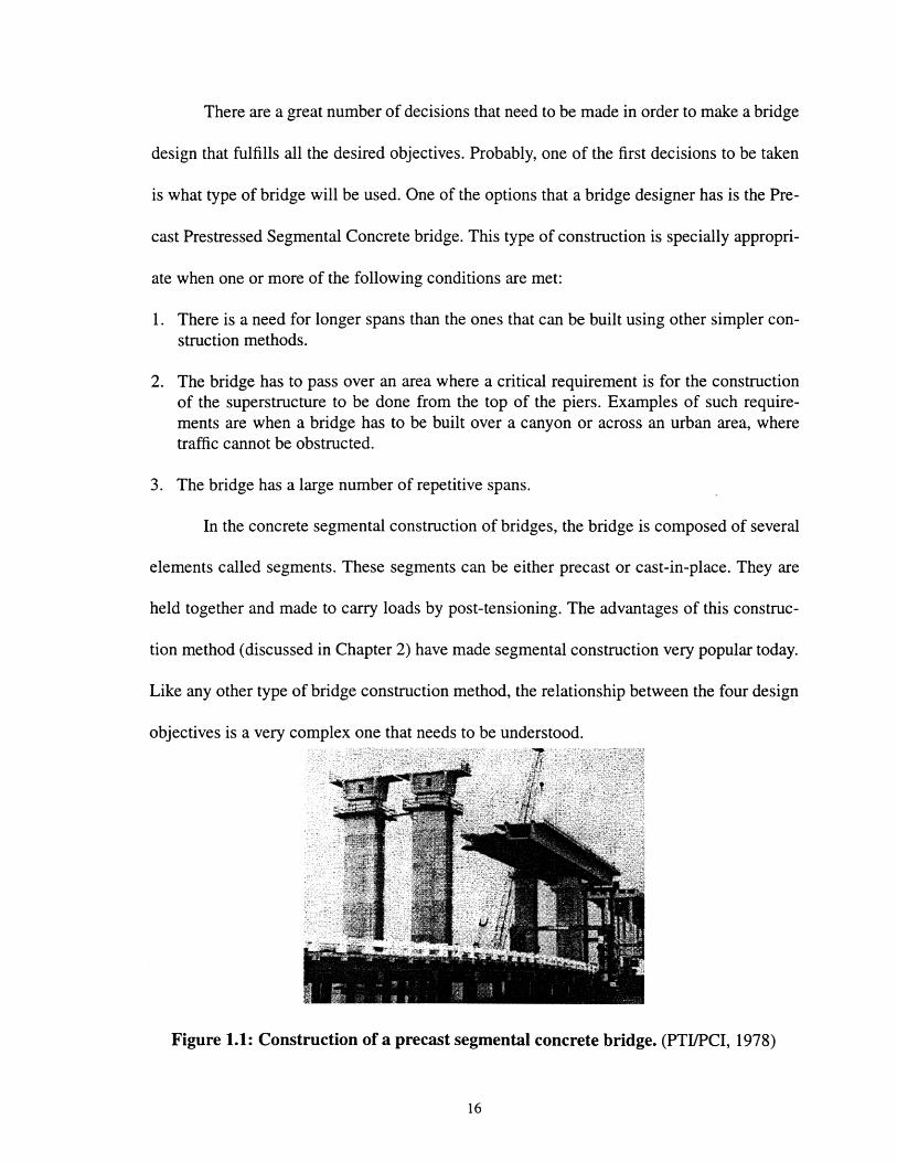
Figure 1.1: Construction of a precast segmental concrete bridge. (PTI/PCI, 1978)

1.2 The Tren Urbano Project
The Tren Urbano is a rapid transit system being designed and built for the metropol-
itan area of San Juan, Puerto Rico. The system includes elevated, underground and ground-
level rail transit sections.
The first section of the Tren Urbano Project is known as the Bayam6n contract. It is
currently under construction and is scheduled to be finished by September of 1999. It con-
sists of an elevated railway of 2.9 km length.
The elevated railway design of the Bayam6n phase is composed mostly of two-span-
continuous units, formed by precast box segments, seated in epoxy, and held together by
prestressing steel cables. At the beginning and at the end of each unit, expansion joints and
elastomeric bearings are used.
The design of the Bayam6n phase will be covered in more detail in Chapter 4.
Before covering the design in detail, it is important to know the past history of bridges in
Puerto Rico, so that likely problems can be anticipated.
1.3 Bridges in Puerto Rico
When posed with the question: "What is the major source of problems with bridges
in Puerto Rico?", most bridge experts would probably answer: "expansion joints".
This is not a problem that is unique to Puerto Rico. Expansion joints are a source of
problems for bridges around the world. If there are problems with the sealing system of the
joint, leaks can occur. Therefore, there can be corrosion in the reinforcement steel and in the
bearing system, and stains noticeable on the columns. Protection against corrosion is very
important in Puerto Rico, given that it is an island and has a lot of salt in the air. Without
enough cover, reinforcement steel quickly corrodes.
Another problem typical in Puerto Rico is that the expansion joints themselves dete-
riorate. This deterioration can be felt by a rider in a moving vehicle as a bump. How uncom-
fortable and noisy the bump is will depend on how deteriorated is the expansion joint. The
deterioration will also cause stresses that were not accounted for in the guideway design.
The causes of problems with expansion joints are: improper installation and poor
inspection and maintenance. It is generally believed in Puerto Rico that if expansion joints
were properly installed and given reasonable inspection and maintenance, there would be
no problems with them on the island.
Usually, the highest loads for which bridges in Puerto Rico are designed are earth-
quake loads. Although there has not been an earthquake in Puerto Rico since 1918, the
island is located in an earthquake prone zone. Recent events in California and Japan make
designing for earthquakes a field that is increasing in importance and sophistication.
Another fact is that bridges in Puerto Rico are mostly built using simple spans. Very
seldom do designers try to take advantage of using continuous units. They seem to be
extremely cautious about changes in length due to changes in temperature, which is very
strange because the temperature in the Puerto Rico does not goes through such drastic
changes as it does in other parts of the world. It also appears that not many designers are
willing to go through the more complicated procedure of designing for continuous spans.
Segmental bridge construction is practically new in Puerto Rico. Only one segmen-
tal concrete bridge has been constructed: the Caguana River Bridge in Utuado, a part of
Highway 10. There are no segmental elevated railways in Puerto Rico. In fact, there are no
railway bridges in operation in Puerto Rico.
1.4 Research Objectives
The objectives of this research are:
a) Improve upon the current design philosophy for the elevated railway structure of the first
phase of the Tren Urbano Project with the hope that these improvements are considered for
adoption in the design of future sections of the project and in future designs similar to the
one presented here. This objective will be achieved by analyzing how the behavior of the
structure would be affected by changes in span continuity (simple span, two-span-continu-
ous, three-span continuous, etc.). Alternative designs might have the following advantages
over the current design:
1. Less vibrations.
2. Smallerodeflections.
3. More stability.
4. Greater resistance and better behavior under lateral loads, particularly earthquakes.
5. Use of fewer expansion joints and bearings, which in turn would mean a structurethat needs less maintenance.
6. Improved appearance.
b) Study the feasibility and economic impact of the alternative designs. Once an optimal
design is found, it needs to be determined as to what is needed to be done to make the
changes and what are the costs associated with these changes. The cost-effectiveness of
making the changes, as compared to keeping the current design, will be studied by perform-

ing a life-cycle cost analysis. This will determine the plausibility of making the improve-
ments to the design.
1.5 Organization
In Chapter 2, the precast prestressed segmental concrete construction method is
introduced, presenting advantages and disadvantages that this method will have in compari-
son with other methods. A general overview on the process of design and construction of
precast prestressed segmental concrete bridges and guideways is given.
In Chapter 3, the four design objectives (safety, serviceability, economy, and aes-
thetics) of bridge structures are discussed. Design issues that may cause the failure of not
achieving the four objectives when constructing the precast prestressed segmental concrete
bridges or guideways are presented.
In Chapter 4, the design of the first phase of the Tren Urbano is presented in detail.
The method of construction is also explained. Possible problems that may arise with the
structure are mentioned.
In Chapter 5, an analysis is performed in order to study the structural impact of
increasing changing the continuity of a bridge structure similar to that of the Tren Urbano
Project. An introduction to the computer program SAP2000 is given. The results obtained
from the analysis using the program are discussed.
In Chapter 6, a Life-Cycle Cost analysis is performed on each of the design alterna-
tives evaluated in Chapter 5.

Finally, in Chapter 7, the results of the analysis presented in Chapter 5 and 6 are ana-
lyzed to show how the four fundamental objectives of bridge design get affected with one
design decision, in this case being increasing continuity of the superstructure. Final recom-
mendations are given on how to improve the design philosophy in the design of bridges.

22

Chapter 2
Precast Prestressed Segmental Concrete Bridgesand Guideways
2.1 Reinforced vs. Prestressed Concrete
Prestressed concrete is defined by the American Concrete Institute (ACI) as: "con-
crete in which there have been introduced internal stresses of such magnitude and distribu-
tion that the stresses resulting from given external loadings are counteracted to a desired
degree. In reinforced-concrete members, the prestress is commonly introduced by tension-
ing the steel reinforcement."
It is known that concrete performs well under compression, but it is not as good
under tension. When prestressed concrete was invented, it was with the idea of achieving a
concrete that did not have any tensile stresses when external loads were applied. As the def-
inition of the ACI says, the prestressing was done by tensioning the reinforcement steel of
the concrete members.
In reinforced concrete, the tensile forces resulting from the bending moments are
resisted by the reinforcing steel, which is put into tension by the bond created in the rein-
forcement process. Therefore it is assumed that the tensile strength of the concrete in rein-
forced concrete is negligible and disregarded. Once a reinforced member reaches its limit
state at service load, the cracking and deflection that occur are practically irrecoverable.
In contrast, in prestressed concrete, the prestressing permits a relatively high con-
trolled recovery of cracking and deflection. In the case the flexural tensile strength of con-
crete is exceeded, the prestressed member starts to act like a reinforced concrete element.
There are certain qualities of prestressed concrete that can make its use more cost-
effective than the use of reinforced concrete. A prestressed member usually has a depth of
about 65 to 80 percent of the depth of a reinforced concrete member with the same span and
loading conditions (Nawy, 1996). This means that there is a saving in materials when pre-
stressed concrete is used. Also, by having shallower depths, the prestressing members can
be lighter than the reinforced members, which means that lighter foundations can be
achieved with prestressed members. In addition, because cracking is reduced, less mainte-
nance is needed and longer working life can be achieved using prestressed members, again
meaning more savings.
By no means do the statements above imply that prestressed concrete its always
more economical than reinforced concrete. In prestressing, a higher quality of materials is
needed. Besides, performing the prestressing is a more complex task than simply reinforc-
ing the concrete, therefore resulting in an additional cost. Which one is more economical
between prestressed or reinforced concrete depends on the specifics of the structure being
designed.
When a beam is being designed for a span longer than 30 meters (like the ones used
in bridges and guideways), if reinforced concrete is used, the cross-section needed to resist
the moments caused by the life loads will be very large. This increases the self-weight of the
beam substantially, causing excessive cracking and deflections. Therefore, the use of pre-
stressed concrete becomes necessary, unless arches are used.
2.2 Non-Segmental Prestressing vs. Segmental Prestressing
Currently, short-span bridges (up to 50 meters) in the United States are most com-
monly build using precast pretensioned concrete I-girders, taking advantage of all the bene-
fits of using prestressed concrete (PCI, 1992). Still, although longer spans can be achieved
with prestressed concrete than with reinforced concrete, sometimes there were requirements
for even longer spans that could not be achieved with just prestressed concrete. Other mate-
rials, like steel, had to be used. Therefore, segmental construction got its start as an alterna-
tive concept for bridging longer spans.
Segmental bridges are those that are constructed from a number of short transverse
segments. Usually, prestressing is applied to segmental bridge construction, allowing the
construction of longer and/or thinner spans. Prestressing is done by using post-tensioning
tendons in the longitudinal direction of the beams.
The most typical configuration in prestressed segmental bridge construction is the
box girder. This is true because in most cases, box girders are the most efficient and eco-
nomical design for a bridge (Podolny and Muller, 1982). In fact, the box girder has been
used in almost every type of bridge construction including simple span, continuous spans,
cantilevers, arches, stayed girders, and suspension. When using box girders, permanent
post-tensioning can also be applied transversely to the top slab to increase the strength of
the deck, and vertically to the webs to increase the shear capacity of the box girder.
The box girders used are mostly single cell and double cell. There have been cases
where three-cell box girders has been used, but these segments need temporary stiffeners to
prevent buckling during construction (Wium and Buyukozturk, 1984).

Since getting started as an alternative to bridging longer spans, segmental construc-
tion continued development because it offers other advantages. One of them is that horizon-
tally curved alignments, humps or sag vertical curves, and transitioned cross slopes can
easily be accommodated with segmental construction. Also, when compared to other types
of construction, segmental prestressed construction can be done by a small work force per-
forming repetitive tasks. Besides, with segmental construction it is possible to reduce signif-
icantly the interference with existing traffic, eliminating expensive detours.
Finally, it is normally believe that segmental construction protects the environment
(Podolny and Muller, 1982). If an elevated guideway is constructed instead of constructing
a highway, a road, or a railway using cut-and-fill type of construction, then an environmen-
tally sensitive area would be less affected with the narrower path of the alignment construc-
tion. Then, if the guideway was constructed using segmental construction, longer spans
would be possible and the construction of the superstructure could be done from top of the
piers, thereby protecting the environment even more.
2.3 Precast vs. Cast-In-Place
As mentioned before, segmental bridges are constructed from a number of short
transverse segments. The segments can be either:
1. Precast, meaning they are manufactured in a precast yard on or off-site, which then aretaken to the bridge location where they are assembled; or
2. Cast-In-Place, meaning they are cast in their final position.
Choosing between any of the two will bring advantages and disadvantages.
The advantages of the using precast concrete over cast-in-place concrete in pre-
stressed segmental bridge construction are:
1. The precast segments can be fabricated while the substructure is being built, whichmeans a saving in construction time.
2. The fabrication of this segments is done by the repetitive use of industrialized manufac-turing techniques. This provides the opportunity of achieving high quality and highstrength concrete.
3. There is no need for falsework and everything can be accomplished from the top of thecompleted portions of the structure. This is very useful when traffic has to remain undis-turbed under the bridge or for high-level crossings.
4. The effects of shrinkage and creep are substantially reduced. This happens because usu-ally, the segments have already matured to full design strength by the time of erectionand post-tensioning.
5. Precast construction is less sensitive to weather conditions than cast-in-place construc-tion.
The advantages of using cast-in-place segments instead of precast segments in seg-
mental construction are:
1. There is no required dimensional control of high degree during the manufacturing anderection of the segments. Connections of the ducts for tensioning cables between seg-ments can be done more easily.
2. There is room for error in cast-in-place construction. If the actual camber does not agreewith predicted camber, corrections can be made as the construction progresses by revis-ing the alignment of the following segments.
3. Joints can be treated better for transfer of bending and shear stresses and for water tight-ness for protection of the tendons. Longitudinal reinforcing steel can be placed betweenthe segments.
4. The size and weight of the cast-in-place segments is not limited to the transportationequipment, as it is for the precast segments.
2.4 Precast Prestressed Segmental Concrete Construction
All the advantages of precast concrete, prestressed concrete, and segmental con-
struction come together in precast prestressed segmental concrete construction. This type of

construction is most widely used in the construction of bridges. In this section, general
aspects of this type of construction for bridges are presented.
2.4.1 Fabrication of the Precast Segments
The fabrication of the segments can be distinguished by the type of joint to be used
between the segments themselves (PTI and PCI, 1978). This joint can either be a cast-in-
place joint or a contact joint. These joints will be discussed in more detail in the Section
2.4.3.
When using cast-in-place joints (also known as wide joints or broad joints), the pre-
cision of line of segments depend more on how accurate is the casting of the joint during
erection and less the accuracy of the segments (PTI and PCI, 1978). Segments using wide
joints can be cast separately.
When using contact joints (also known as match-cast joints), the connecting sur-
faces between the segments fit each other very accurately, so only a thin layer of filling
material is needed for the joint. Sometimes no filling material is needed at all. Segments
using match-cast joints are cast by either long-line method or the short-line method.
In the long-line method (Figure 2.1), all the segments are cast on a long line. One or
more formwork units move along the line. The formwork units are guided by a pre-adjusted
soffit. A long line is easy to setup and to maintain control. After stripping the forms, it is not
necessary to take away the segments immediately. Its main advantage is that similar correc-
tions are usually needed for each span, so that only one base structure has to be built for all
of the spans in the structure.
Unfortunately, the long-line method has some disadvantages. Substantial space may
be required for a long line (usually about half the length of the longest span of the struc-

ture). The long line must be constructed on a firm foundation which will not settle under the
weight of the cast segments. If the structure has a curvature, the long line must be designed
to accommodate for it. Also, the equipment for casting and curing has to move from place
to place since the forms are mobile.
OUTSe9 O tWO*oRK.
PL AN
Figure 2.1: The long-line method. (Barker, 1980)
l8 DC FOOMWOCR
CARRIAGE
Figure 2.2: The short-line method. (Barker, 1980)
In the short-line method (Figure 2.2), the segments are cast at the same place in sta-
tionary forms and against a neighboring segment. After the segment is cast, the neighboring
segment is taken away and the new segment takes its place, so that another segment can be
cast. The space needed for the short-line method is about three times the length of a seg-
ment, small compared to the space needed for the long-line method (PTI and PCI, 1978).
Curves and twisting of the structure can be obtained by adjusting the neighboring segment.
In the short-line method, the elements can be cast in the vertical position to be later used in
the horizontal position.
The short-line method has a disadvantage. To obtain the desired structural configu-
ration, the neighboring segment must be positioned with extreme accuracy.
The length of the precast segment will depend largely on what equipment is avail-
able for transporting, lifting and prestressing. When choosing what is going to be the size of
the segments, it has to be decided between having segments with the same length or having
segments with the constant weight (Wium and Buyukozturk, 1984). Designing for the same
length has the advantage that less adjustments are needed for the formwork. Meanwhile,
designing for constant weight means having the advantage of always transporting and lift-
ing units at full capacity which could reduce the construction time.
2.4.2 Erection Methods
There are four methods used to assemble a segmental bridge: the balanced cantilever
method, the progressive placing method, the incremental launching method, and the span-
by-span method. The method used depends on the length of the bridge or guideway, the
individual span lengths, the height of the superstructure along its length, access to the area
below where the superstructure is going to be, and the available equipment.

In the balanced cantilever method, a segment is placed on top of a column and
securely anchored so that it can resist large overturning moments. This segment can be
either cast-in-place or precast. Then, other segments are put on each side of the pier, one at
a time alternating from side to side, stressing tendons that go through the segments and over
the pier. Segments on both sides of the pier balance each other. When the number of seg-
ments on each side of the pier is not equal, there is a large unbalanced moment at the col-
umn. The procedure is repeated until the cantilever segments from adjacent piers meet at
midspan. The segments used can be either precast or cast-in-place.
The progressive placing method is very similar to the balanced cantilever method.
The difference is that the construction starts at a pier and proceeds in only one direction.
Therefore, in this method, a cantilever can be almost as long as the length of the span being
constructed. The bending moments on the columns are substantial, often requiring the use
of temporary intermediate supports.
In the incremental launching method, the construction of the superstructure is per-
formed from the top of an abutment. A segment is cast on top of the abutment. The segment
is cured and prestressed, and then moved forward, so that a new segment is cast against this
segment. Then, prestress is applied to the segments, and both segments are moved forward.
This procedure is repeated, and the superstructure spans from pier to pier until it is com-
pleted. Very often, a steel launching nose is attached to the deck of the first segment in order
to reduce the free cantilever length of the first span. Temporary piers or temporary stays
might be used in cases where the negative moments are too large.
In the span-by-span method, a supporting system is used to place all the segments of
a given span during construction. This structure can be a truss fixed at the columns that sup-

ports the segments (in case of precast construction) or formwork (in case of cast-in-place
construction) from below, or it can be a truss that holds the segments or formwork from
above the deck. Since this method uses the truss, the length of the spans of the bridge to be
constructed is limited to the length of the truss.
The method used to erect precast units for any of the previous methods will depend
on the site conditions. They can be lifted and put in place by using a crane on the ground or
a barge. They can be lifted using equipment on the deck of previously erected units, or, in
the case of erection using the span-by-span method, they can be placed using a launching
gantry.
The launching gantry can be supported by the completed piers, by the completed
parts of the superstructure, or by both. They are very expensive and are only used economi-
cally in large projects. They are very useful when the area under the superstructure can not
be used for the delivering of precast units or for operating erection equipment.
2.4.3 Joints
When placing the segments to create the superstructure, the segments can be placed
together using contact joints or cast-in-place joints. One type of contact joint is the dry joint,
which does not need any filling material between the segments, but the most popular is the
epoxy joint. In the epoxy joint, the adjacent segments have matching surfaces, and a very
thin layer (less than 1 millimeter) of epoxy coating is used between the segments.
Epoxy has many uses. It acts as a lubricant when placing the segments and works as
a glue that helps the segments act as a single unit. Also, epoxy helps correct some of the
irregularities between the mating surfaces of adjacent segments, and serves as waterproof
material for the joints between segments.

Cast-in-place joints are made using mortar and concrete. They are wider than the
epoxy joints. Mortar or unreinforced concrete has been used frequently for joints between
segments of 24 to 100 millimeters. Reinforced concrete has been used for joints from 200 to
600 millimeters, where the reinforcing steel from adjacent segments is lapped or welded
together (Degenkolb, 1977).
Mortar and concrete joints do not require the exact fitting that epoxy joints need, but
they are not suited for cantilever construction. This type of joint is mostly suited for con-
struction using falsework.
Today, almost all the joints used in segmental construction are contact joints. Cast-
in-place joints are mostly used when the alignment needs to be corrected (Wium and
Buyukozturk, 1984), and to make a a final adjustment in a span of contact joints.
2.4.4 Railroad Bridges and Guideways
Segmental prestressed construction is as suitable for rail transit and railroads as it is
for highways. The procedure for designing an elevated railway is similar to that of a high-
way bridge. The difference lies in the larger design life and impact loads for railroad struc-
tures. Therefore, elevated railways are more stocky than highway bridges.
In the case of a railway bridge, the actual load applied to the structure is much closer
to the design load than in the case of a highway bridge. Therefore, fatigue and durability of
railway structures could be a problem and need careful consideration (Podolny and Muller,
1982). This is made even more important due to the fact that the maintenance and repair of
railway structures could cause unacceptable disturbance in the train operation.
Usually, ballast is used across the railroad bridge so that the ties and rails are kept in
proper alignment and grade separate from the bridge structure. Typically, for rail transit, the

ballast is not used, and either the ties are fixed directly on top of the deck, or the track is set
directly on pads and shims attached to the bridge deck, eliminating the use of ties and bal-
last. When using ties, they can be made of wood, steel, reinforced concrete, or prestressed
concrete. Whichever system is used to fixed the track to the deck, it should have drains or
sufficient slope so that water is not trapped.
Until about 30-40 years ago, all tracks, in all networks, were laid by leaving gaps
between consecutive rails, and then jointing the rails with fishplates (Profillidis, 1995). The
gaps and fishplates were used to permit elongations in the rail due to temperature changes.
The use of fishplates has many problems (Profillidis, 1995):
1. It significantly reduces passenger comfort.
2. It causes considerable wheel and rail fatigue and wear.
3. A bumping noise is produced when the vehicle's wheels run on top of it.
4. It greatly increases maintenance expenses.
An alternative to jointed rails is the continuous-welded rail (CWR). A CWR is
formed by putting together discrete pieces of rail, eliminating the use of fishplates. No ther-
mal expansions along the length of the rail are permitted. This generates forces in the rail
that it must be able to resist.
The cost of installing CWR is higher than that of installing a jointed rail. Neverthe-
less, the CWR provides an adequate return in capital for the initial investment by reducing
maintenance cost, improving track stability, permitting the achievement of higher speed by
the vehicles, reducing power consumption, slowing the development in track defects, reduc-
ing noise, and improving passenger comfort (Profillidis, 1995).

There is a tendency to use continuous-welded rails wherever possible (Fryba, 1996).
However, with the introduction of the continuous-welded rail into railroad bridges and
guideways, a new problem came up with regard to the interaction between the superstruc-
ture and the rail. New forces and stresses are developed with changes in temperatures. This
problem is presented in more detail in Chapter3.

36
Chapter 3
Design Considerations for Precast Prestressed SegmentalConcrete Bridges and Guideways
3.1 Introduction
Bridge design for any kind of bridge, including precast prestressed segmental con-
crete bridges, should always have the same fundamental objectives. In this chapter, these
fundamental objectives of bridge design are presented, and what it means to achieve these
objectives is discussed. Later in the same chapter, major issues concerning precast pre-
stressed segmental concrete bridges are discussed, and how they affect the accomplishment
of the fundamental objectives is analyzed.
3.2 Design Objectives
The fundamental objectives of bridge design are safety, serviceability, economy and
elegance. A design can only be successful when all four goals have been achieved. The rel-
ative importance of each objective is going to be defined by the consequences of not achiev-
ing them (Menn, 1990). Things get further complicated by the fact that all four objectives
are interrelated. For example, it is possible that making a structure more aesthetically pleas-
ing may mean added costs that would make it less economical.
3.2.1 Safety
A bridge is safe when it is known that it is not going to collapse under the applied
loads. The achievement of safety for a bridge structure is mostly believed to be scientific
process (Menn, 1990). A bridge designer follows design codes, and a bridge is designed to

resist ultimate loads. When an ultimate load is applied and the structure resists the load,
then it is said that the applied and resisting loads are in equilibrium. If an applied load
exceeds the value of an ultimate load, the structure is not in equilibrium and, therefore, col-
lapses. If all the steps in the design and construction process are followed accordingly, and
if the structure is inspected properly and given the necessary maintenance, the bridge is said
to be safe, and the structure is not supposed to collapse as long as the values of the ultimate
loads are not exceeded.
The fact is that the value of both, the loads to which the structure is subjected and
the ultimate load which the structure can resist, are not known exactly. Both are functions of
many different factors. Among other things, the loading will depend on the actual traffic
patterns that use the bridge, the wind loads and earthquake loads to which the structure is
subjected, the settlements taking place in the foundations, and the changes in temperature
that occur in the structure. Likewise, the ultimate load the structure resists will depend,
among other things, on the actual strength of materials, the workmanship given in the con-
struction, the deterioration the structure suffers, and the inspection and maintenance given
to the structure. That is why design codes have factors of safety included in their procedure.
There are factors of safety that make the expected applied load larger, and factors of safety
that make the expected structure resistance lower.
Design codes are not infallible. Bridges that have followed design codes have been
known to collapse. Sometimes this is because the applied loads were larger than expected,
even with the use of factors of safety. At other times it was because the structure was not
constructed according to its design, or because it was not given the proper inspection and
maintenance. At times design codes improperly simulate the structural action of bridges.

The factors of safety and equations found in design codes are trying to simulate
what will happen to the structure in reality. Sometimes the simulations are not as close to
reality as they need to be. Therefore, codes are revised and changed, trying to get closer to
reality and helping in the design of safer structures.
In spite of all of the above, safety is not only achieved by following the design
codes. The codes do not specify which material to use for construction, what method of
construction to use, how to arrange the components of the structures, and many other issues
that arise in the design phase. These issues, that have to be decided by the designers, are
also going to play a role in determining how safe the structure will be. Therefore designers
must use their creativity and common sense, as well as their personal and observed experi-
ences with similar projects. It is good to know what has gone both, right and wrong, with
similar projects so that this knowledge can be used in the design of a safer structure.
3.2.2 Serviceability
Serviceability is an issue very similar to safety. It is sometimes believed to be
achieved completely through scientific procedures by following design codes (Menn, 1990).
In reality, this will also depend on the creativity, common sense, knowledge, and experience
of the designer.
A bridge is serviceable when it fulfills the need for which it was designed in a posi-
tive manner. The most important aspects of serviceability are appearance, function, and
durability (Menn, 1990). Appearance refers to giving the impression that the structure is
secure. The showing of cracks and large deflections can give the impression that a structure
will fail if used, although it may not. Function refers to how the bridge works when used.
The bridge should be safe for the users (and for any traffic that passes under it) during both

normal and emergency conditions. It should not be uncomfortable, and it must meet the
requirements of abutters and the aspirations of the community as a whole. Finally, durabil-
ity refers to remaining in service or remaining fit for use for a long period of time.
There are aspects of serviceability that can be quantified such as deflection, vibra-
tion, cracking, run-off of rain water on the deck, and traffic volumes. These aspects can be
fulfilled by following design codes and following proper construction procedures. Other
aspects, that can not be quantified, need of the creativity and experience of the designer to
be provided, for example, corrosion of the bearing system. The designer should think of
protecting the system against corrosion, and provide for easy inspection and replacement of
components in case of corrosion.
A bridge will deteriorate with time. The more serviceable will deteriorate slower. In
any case, all bridges need inspection. Therefore, inspection is very important in maintaining
a bridge serviceable, like proper design and construction are too.
3.2.3 Economy
Economy in bridges is about getting as much as possible out of money. It is not
about spending the least possible amount of money in the construction of the bridge. The
big picture has to be seen, and costs incurred in operation, maintenance, rehabilitation, and
demolition of the bridge have to be considered too.
When a bridge is designed, a number of decisions have to be made. These decisions
will impact the cost of construction, and other costs in the long run. They include the selec-
tion of materials, the type of construction to be used, how will the workers get organized,
details of the structure, and the equipment to be used. Also, an appropriate strategy has to be
established for construction, maintenance, rehabilitation, and ultimate disposal.

As mentioned earlier, every bridge deteriorates. The difference is how fast they dete-
riorate. This will depend on those very first decisions made for the construction phase. How
it deteriorates will impact the operation of the bridge and the maintenance needed for the
bridge to remain serviceable. Also, how the bridge deteriorates will determine if the bridge
needs at some point in the future a major rehabilitation, or how can it be disposed of the
structure in the case is deemed the bridge is not useful anymore. Operation, maintenance,
rehabilitation and demolition represent costs, and they can be very substantial.
The important thing to remember here is that when aiming for cost-effectiveness in
the design of a bridge, the future operation, maintenance, rehabilitation and demolition, as
well as the present (or immediate future) construction costs must all be thought of. The best
tool the designer has to determine the cost effectiveness of a bridge is the life-cycle cost, in
which the total cost of the bridge is calculated for the life-span that the bridge is designed
for.
3.2.4 Aesthetics
The issue of achieving aesthetics in bridges can, at first, appear to be very compli-
cated, because beauty is believed to be very subjective. In reality, by checking the literature
written by experts in aesthetics of bridges, it can be found that there is agreement on most of
the major issues of elegance in bridges.
The experts agree that bridges must be adequate for their surroundings, whatever
they are. As Ritner (1990) explained: "visual beauty is something that is not awkward, it is
something that does not appear to be out of place". At the same time, the bridge structure
can be perceived as an individual entity (Menn, 1990, 1991), therefore its beauty will also
depend on the bridge's structural form.
Commonly believed ways of achieving an elegant bridge include: using efficiently
the materials for a structure that is slender and transparent as opposed to heavy and massive;
integrating harmonically all the structures components into one coherent, organized struc-
ture; making the structure symmetrical; designing for simplicity without unnecessary orna-
mentation; and, incorporating topographical features of the surroundings.
As for safety, serviceability, and economy, when designing for aesthetics, the future
must be kept in mind. How the bridge will deteriorate has to be considered, along with what
kind of maintenance must be given to keep its elegance has to be thought through.
In many cases, the first obstacle that has to be crossed in order to get an aesthetically
pleasing bridge is to have the bridge designer understand that making a bridge more elegant
does not always means having a more expensive structure. Sometimes money has been
saved by changing a bridge design to make it more elegant. And in the cases where making
a design more elegant means an increase in cost, the changes should not always be dis-
carded just for the sake of saving money. The designers have to understand that the public
does care about having an aesthetically pleasing bridge, approaching the decision of adding
cost for elegance as they would do for adding a safety feature that would increase the cost of
the bridge (Gottemoeller, 1990, 1991).
The majority of bridges are designed by engineers who have no formal education in
aesthetics. That is why the engineer must work together with a person who does have the
formal education: the architect (Lacroix, 1990). It is in public agencies on whom the
responsibility of designing, building, maintaining, and as consequence, achieving elegance
in bridges falls (Kruckemeyer, 1990). Therefore, they should get architects to be involved in
the design of public bridges.

3.3 Major Issues in the Design of Precast Prestressed Segmental ConcreteBridges and Guideways
In 1994, the American Segmental Bridge Institute (ASBI) published in the PCI Jour-
nal the results of a survey in which the performance of 96 segmental concrete bridges of the
United States and Canada was evaluated (Miller 1994). The major conclusions of this report
were:
1. Segmental concrete construction performs well over time, with consistently high condi-tions ratings for bridges that have been in use for up to 30 years.
2. The performance of post-tensioned segmental concrete is similar to that of other pre-stressed concrete bridges.
Though it has been found that precast prestressed segmental construction is a very
good method of construction, it is still not perfect. In this section are presented important
design decisions and possible sources of problems related to precast prestressed segmental
concrete bridge. Some of the decisions and problems are not exclusive to precast pre-
stressed segmental construction. It will be shown how these decisions and problems will
affect the achievement of the four before mentioned objectives of bridge design.
3.3.1 Continuity
One decision to be made in a bridge or elevated guideway design is what kind of
span configuration should be used. Basically, a decision must be taken between using sim-
ple spans or a continuous system. Furthermore, if a continuous system is selected, then a
continuous unit needs to be chosen (two span continuous, three span continuous, etc.).
Selecting a continuous system over the use of simple spans will have an effect on a number
of important aspects of the structure. Some of these effects are positive, and some are not.

In a simple span configuration, the maximum moment on each beam occurs at mid-
span, while the moments at both ends are zero. If the configuration is changed to continu-
ous, the moment at midspan is reduced, while the maximum moments occur on the section
of the unit that passes on top the support continuously. The moments at the end of the con-
tinuous unit are zero.
A problem with using a continuous design is that it is much more difficult than mak-
ing the design of a bridge in which all its spans are simply supported. It is important that the
bridge designer realizes that there are many possible advantages that can be taken out of
designing a more continuous structure and that it is worth going through the trouble. Not
exploring the possibility of using a continuous system could mean not achieving the four
objectives of bridge design.
Safety
If a bridge design is changed from using simple spans to using continuous units
while the size of the cross-section is not changed for the new design, the stiffness of the
girders would be increased. Therefore, the continuous unit could resist heavier loads than
the simply supported member.
Another advantage obtained by using continuity is that the over-all structural stabil-
ity is improved through redundancy. Continuity increases safety margins by allowing the
redistribution of stresses under overload conditions (Taly, 1998). Also improved is the
response to dynamic loads such as earthquake and wind loads. This happens because
increasing the continuity of the structure means having more columns connected to the
girder, which is what causes the improvement of stability, and provides a better mechanism
to resist horizontal loads.

Another way of improving resistance of lateral loads, is that by increasing continuity
of a design, the maximum moments at mid-span are reduced, therefore allowing for a reduc-
tion in the size of the girder cross-section. This reduces the weight of the structure which, in
turn, reduces the momentum of the structure, which reduces the lateral loads to be resisted
(Taly, 1998).
Is not always better to increase continuity. As explained before, in the columns
where the superstructure pass over continuously, there is a concurrence of moment and
shear at the support sections, which reduces the moment strength at this locations. Also at
these columns, new lateral forces and moments are formed. These forces are caused by the
elastic shortening of the long-span beam under prestress, and by horizontal loading that
could come from earthquakes, acceleration and breaking of vehicles, and temperature
changes. Additionally, the secondary stresses, usually produced by shrinkage, creep, tem-
perature variations, and settlement of the supports, are magnified when compared to a sim-
ply supported structure. All these possibilities need to be considered, and the supports may
need more reinforcement, be made more flexible or made larger.
Another possible problem that could present itself if the continuity of a bridge
design is increased is the reversal of moments. If live loads are much heavier than dead
loads, and if partial loadings on the spans are considered, the beam can be subjected to seri-
ous reversal of moments. This problem could be addressed for by using partial prestressing
(in which some tension is allowed in the concrete).
Serviceability
By changing a bridge design from using simple spans to using continuous units, if
the size of the cross-section that would be used for the simple span design is kept, the stiff-

ness of the girder would be increased. Therefore, the continuous units would have a smaller
deflection than the simply supported.
The number of expansion joints and bearings used could be reduced by increasing
the continuity of the bridge. This means that the structure would require less of the inspec-
tion and maintenance associated with expansion joints and bearings. Other problems associ-
ated with expansion joints, such as leakage, and corrosion of the reinforcement and the
bearing support system, could be minimized. Also, by reducing the number of expansion
joints, the number of bumps felt by riding over them is reduced, thus the ride comfort is
improved.
The problem with an increase in continuity is that there are going to be greater elon-
gations at the free-ends caused by an increase in temperature. Therefore, bigger and more
complex expansion joints have to be provided. It is more difficult to provide sealant for
these joints.
Economy
If a bridge design is changed from simple span to continuous, the size of the cross-
section can be reduced due to the reduction of the maximum moments and stresses at the
midspan. Having a smaller cross-section means a reduction in the cost of materials and,
possibly, construction. Also, the structure would be lighter, which means that the columns
and foundations can be lighter, which, in turn, means further reduction in the cost of materi-
als and, possibly, construction. Alternatively, the span length could be increased with conti-
nuity which, in turn, could mean that the number of piers to be constructed could be
reduced.

By increasing continuity, the number of anchorages needed to tension the steel at
intermediate supports can be reduced when compared to the quantity used for simply sup-
ported members. This means further reduction in costs and labor.
The number of expansion joints and bearings is reduced by increasing the continuity
of a bridge. This means that the structure would require less inspection and maintenance,
and therefore, there would be a reduction in cost. Sometimes, depending on the develop-
ment of new lateral stresses, the width and thickness of the piers can be reduced by reducing
the number of bearings, which means further savings of materials. Other problems associ-
ated with expansion joints, such as leakage and corrosion, could be minimized, therefore the
possibility of having to perform what could be a very costly bridge rehabilitation are
reduced.
In continuous beams, various spans can be prestressed with the same continuous
tendon by providing and undulating profile, resulting in the reduction of anchorages needed.
This is not always possible, because there could be a non-acceptable reduction in the pre-
stressing force when continuous tendons are used due to the friction between the prestress-
ing steel and the duct through which the steel pass caused by the increase number of bends
that the tendon has to go through.
Various disadvantages that come with continuity are: the concurrence of moment
and shear at the support where the superstructure passes over continuously; excessive lateral
forces and moments at this supports due to the elastic shortening of the long-span beam
under prestress and by horizontal loading that could come from earthquakes, acceleration
and breaking of vehicles, and temperature changes; and, the secondary stresses, usually pro-
duced by shrinkage, creep, temperature variations, and settlement of the supports, are mag-

nified when compared to a simply supported structure. Therefore, these supports require
more reinforcement, unless the reduction of the moment strength at this section is accept-
able.
Aesthetics
As mentioned before, continuity allows the reduction of the cross-section of the
beam. This permits having a slender, hence more elegant, structure than a bridge that uses
simple spans.
Again, by increasing the continuity of a bridge, the number of expansion joints and
bearings needed could be reduced. This causes the reduction of the possible leakages of the
expansion joints that causes the staining of the substructure (Wasserman, 1991). Also, by
reducing the number of bearings, the width and thickness of the piers can be reduced, which
makes the structure more aesthetically pleasing (Menn, 1990).
3.3.2 Expansion Joints
Another important decision that has to be made when designing a bridge or a guide-
way is the selection of expansion joints to be used. The ones chosen must be fit to handle
displacements of the structures such as those caused by the changes in temperature or seis-
mic loads. According to David J. Lee(1994): "expansion joints should, more correctly, be
known as movement joints since they cater for relative movement between bridge deck
spans and abutments resulting from a number of causes not exclusively due to the tempera-
ture".
There are two ways in which expansion joints can be classified. The first way is by
classifying them as either open gap or covered gap (K6ster, 1969). The use of this classifica-
tion has to do with the riding quality of the expansion joint when the joint is used in high-

ways, as opposed to when it is used in rail transit, where the vehicle does not make contact
with it. The classification has nothing to do with the sealing used. The other method of clas-
sification is based on the size of the movement the joint has to take into account. They can
be classified as joints for small movements, for medium movements, or for large move-
ments (Lee, 1992).
All over the world, bridges deteriorated due to faulty expansion joints. Usually these
joints have defective or ineffective waterproofing, or poor drainage details.
Serviceability
Expansion joints are located in an extremely vulnerable position. They are subjected
to the impact and vibration of traffic, and exposed to both the effects of the natural elements
(water, dust, grit, ultra-violet rays, and ozone) and applied chemicals (salt solutions, cement
alkalis, and petroleum derivatives).
The expansion joints must fulfill the following conditions (Lee, 1994):
1. accommodate horizontal and vertical movements of the structure;
2. withstand applied loadings;
3. be hardly noticeable when ridden on top of it, therefore not being a hazard to any kindof road user;
4. resist corrosion and withstand attack from grit and chemicals;
5. require little maintenance;
6. permit easy inspection, maintenance, repair or replacement.
7. prevent the penetration of water, silt, and girt, or provide for their removal.
The lifetime of the expansion joint will depend on the chosen model, the type of
structure which it serves, the quality of the workmanship given at installation, and the traffic
it is subjected to (Chabert and Ambrosino, 1996). Problems have been registered with

expansion joints for the seven conditions mentioned above. When expansion joints are not
performing well (either because of improper design or improper installation), they can be a
nightmare for the serviceability of a bridge.
If an expansion fails while the joint is used in a highway bridge, it becomes quite
noticeable to the riders in vehicles. Also, if the waterproofing fails, damage can be caused to
the reinforcing steel of the beams end that the joint is supposed to protect, accelerating the
deterioration of the bridge. The elastomeric bearings can also get affected with the corro-
sion of its reinforcing steel. The same can happen to the piers. The fact that the expansion
joint fails means that it is going to need replacement, creating additional maintenance for
the bridge. Also, the deterioration of the joint causes new forces and stresses in the bridge
that were not accounted for in the design.
Therefore, it is important to give special attention to expansion joints. When care-
fully designed and detailed, properly installed, and given reasonable maintenance, expan-
sion joints should be trouble-free for many years.
Economy
There is a large selection of expansion joints in the market. It is important to choose
one that gives good performance and trouble-free life for at least as long as that of the sur-
facing. They should be properly installed, and given the necessary inspection and mainte-
nance. Otherwise, the expansion joint could start producing problems that could be costly to
fix. If they don't work properly: they could permit leakage that could cause the corrosion of
reinforcement and of the bearing system; and they would have to be replaced with new
expansion joints.

Aesthetics
The major aesthetic problem that expansion joints present is leakage. Those that
permit the passage of water borne chemicals, solids, and pollutants stain and discolor the
structure which can significantly alter and detract from the elegance of the structure (Wat-
son, 1996).
3.3.3 Bearings
Another important decision that has to be made when designing a bridge or a guide-
way is the selection of the bearings to be used. The bearings chosen must be fit to handle
displacements of the structures such as those caused by the changes in temperature or seis-
mic loads.
Bearings can be classified broadly into three groups: mechanical bearings, elasto-
meric bearings, and a combination of both. Mechanical bearings are usually regarded as
rigid, while elastomerics are elastically yielding.
In mechanical bearings, movements and rotations are accommodated by rolling,
rocking or sliding action, usually of metal parts. Much use is made of low friction plastics in
the sliding surfaces. In elastomeric bearings, movements and rotations are accommodated
by compressing or shearing layers of rubber-like materials. They can be long strips, plain
pads or laminated, that is, several rubber-like layers interleaved with and bonded to thin
sheets of steel.
There exist intermediate types of bearings. For example, a bearing where an elas-
tomer is used as the rotation medium, but horizontal movement capacity is provided
mechanically.
Serviceability
Bearings are used to take care of all kinds of movements that a bridge could face.
Sources of movement in bridges are:
1. temperature and humidity changes;
2. creep, shrinkage and fatigue effects;
3. axial and flexural strains arising from dead loading, live loading, prestressing, etc.;
4. dynamic load effects;
5. overload;
6. tilt, settlement or movement of ground;
7. mining subsistence;
8. seismic disturbance;
9. moving parts of structures;
10. erection procedures.
Generally, bridge bearings fulfill the following functions (Lee, 1994):
1. They transfer forces from one part of the bridge to another, typically from the super-structure to the substructure.
2. They allow movements of one part of the bridge in relation to another.
3. They allow free movement in some directions but not in others.
Bearings should normally be designed to last as long as the bridge in which they are
placed. The problem with metallic bearings is that can suffer corrosion and subsequent seiz-
ing and collapse. Meanwhile, improper maintenance of the non-metallic materials may
reduce the serviceability life of the bearing.
It is important to provide for the inspection and the replacement of bearings in
whole or in part. Provisions should be made for the installation of jacks necessary for the
removal of bearings or any part thereof, insertion of shims or any other operation requiring
lifting of the bridge deck from the bearings. This operations should be completed with min-
imal difficulty.
Bearings should be detailed without crevices and recesses that can trap moisture and
dirt. The materials used in their manufacture and the method adopted for protection against
corrosion should be such as to ensure that the bearings function properly throughout their
life. Dissimilar materials that can give rise to corrosion currents should not be used. Special
precautions should be taken when a bearing is used in aggressive conditions, such as a
marine environment.
Bearings must be put in places where they are able to operate as intended. Any sec-
ondary effect produced by eccentric loading or by movements not along a major axis of the
bearing should be taken into account in the design of the bearings.
Economy
In particular for bearings, a decision must be made between bearings of low cost that
need a lot of maintenance and have a short life-span, or more expensive bearings that need
less maintenance and a have a longer life. The selection should be made carefully, probably
with the help of calculating life-cycle costs, which should include costs of installation,
inspection, maintenance, and replacement of the bearing.
The lifespan of a bridge can depend on the time of life of the bearings used. Spend-
ing more money on bearings can result in an overall cheaper structure (due to reduction in
bending moments) with a longer time of life.
Aesthetics
Bearings are usually designed only with structural performance in mind, forgetting

about their aesthetic impact (Watson, 1996). The area of the location of bearings are a
source of aesthetic problems. When using bearings, the width and thickness of the piers
needs to be increased which makes the structure less aesthetically pleasing (Menn, 1990).
Also, the use of bearings can provide enough space between the top of the pier and the bot-
tom of the beam for birds to make their nests, whose defecation could make a bridge less
elegant and cause deterioration due to the acid and humid nature of the droppings.
3.3.4 Fabrication of Precast Segments
There are two methods of fabricating precast segments: with cast-in-place joints and
with contact joints. These methods are discussed in more detail in Section 2.4.1.
Economy
There are certain problems that can occur during the fabrication of precast segments.
These problems are economically related because, if these problems were to occur, the seg-
ment or segments would need to be fabricated again, creating an additional construction
cost. All of them can be avoided if proper construction procedures are followed.
Since precast prestressed segmental concrete bridges are designed to very close tol-
erances, it is important to ensure that the concrete reaches the specified strength at an early
age in order to be able to transfer prestressing forces to the concrete. Therefore, a low water-
cement ratio is used for the concrete, but this reduces its workability, and makes it difficult
to compact. Proper quality control is therefore needed to reduce the variability in the con-
crete strength. Doing so will allow the reduction of the target strength while producing a
concrete with sufficient strength, but with better workability (Wium and Buyukozturk,
1984).

Sometimes steam curing is used in the fabrication of the precast segments. If the
steam curing is applied too early, it could cause the cracking of the segments. It has been
suggested that steam should only be applied after four hours have passed since the placing
of the concrete.
Problems can occur when an element being cast has a different temperature than the
elements that is being cast against. This is due to the heat generated by the curing concrete
of the segment being cast. It could cause the elements not to fit properly anymore after the
concrete is cured. Therefore, ample heat should be applied so that both elements have the
same temperature, and the joints can match perfectly after the segments cool off (Wium and
Buyukozturk, 1984).
Segments should not be placed on top of poor bearing surfaces before being erected.
This way, warping and permanent deformations are avoided (Wium and Buyukozturk,
1984).
All the problems mentioned above are economy related, because if they occur it will
mean that a segment or various segments will need to be fabricated again.
Other problem that does not necessary means the fabrication of a new segment is the
complexity of the section, which makes it hard to compact the concrete during casting. This
can cause the problem of honeycombing, which can be very costly to fix, and thus is econ-
omy related (Casey, 1982).
3.3.5 Joints
There are two kinds of joints used with precast prestressed segmental concrete con-
struction: cast-in-place joints and contact joints. Joints are discussed in more in detail in
Section 2.4.3.
Serviceability
Joints between segments should be carefully designed and constructed. They must
transmit normal and shear stresses, but they should also be designed to require as little
maintenance as possible. Joints must prevent the entrance of water into the prestressing
ducts, therefore protecting the tendons from corrosion.
In some precast prestressed segmental concrete bridges, contact joints have failed
because the epoxy was not handled properly during the mixing and application procedure,
particularly in rain and cold weather. The negative effects of this problem can be largely
reduced by designing shear keys in the webs (Podolny and Muller, 1982).
Also when using epoxy joints, tendons should not be threaded until after the epoxy
has reached its design strength. Otherwise, the high stresses caused by the already placed
tendons can cause the epoxy to bleed and block the ducts where tendons have not been
placed yet.
Economy
If the joints are not properly designed and constructed, the rehabilitation of the
bridge can be very costly. This is especially true if the joint allows the water to get into the
ducts, permitting the corrosion of the tendons.
The fabrication of cast-in-place joints requires a long curing period of time. There-
fore, additional equipment might be required to hold the new segment in place while the
joint achieves its working strength (Wium and Buyukozturk, 1984). Still, they might be nec-
essary to correct the alignment of the bridge.
Aesthetics
Joints can be an aesthetic problem because they can make the structure divided,

instead of the preferably continuous appearance. This can be especially true for the case
when cast-in-place joints are used, and the concrete between the joints and the segments is
of different color. In the case when contact joints are used, if there is oozing epoxy between
the segments, the discontinuity is accentuated, besides having non pleasing stains.
3.3.6 Ducts, Prestressing Tendons, and Anchors
Steel tendons are normally installed in precast prestressed segmental concrete
bridges by being pulled or pushed through voids in the concrete formed by ferrous metal
tubing known as ducts. Commonly, galvanized metal tubing is used (PTI/PCI, 1978).
All ducts must have sufficient grouting inlets, vent pipes and drains, to permit proper
grouting and to avoid accumulation of water inside the ducts. Inlets and/or vent pipes shall
be located at all high points of the tendon profile (PTI/PCI, 1978).
Post-tensioning tendons are used to apply both temporary and permanent prestress-
ing forces to the precast segmental concrete bridges. Permanent post-tensioning is required
for the primary longitudinal reinforcement, and sometimes is used in the top slab to provide
transverse post-tensioning, and in the webs for vertical post-tensioning. At other times, per-
manent post-tensioning is used to provide a permanent connection between the superstruc-
ture and the piers (PTI/PCI, 1978).
Temporary post-tensioning is used during cantilever construction. Permanent post-
tensioning is not applied only after a segment has been erected at each end of the cantilever.
Therefore, during the placing of the first segment at one end, the element is attached to the
cantilever using temporary post-tensioning (PTI/PCI, 1978).
The anchorages for permanent longitudinal tendons may be located at either the
webs in the face of the segment, or in special web stiffeners cast into the segment for the

purpose of providing a location for anchorage that does not interferes with the erection pro-
cess (PTI/PCI, 1978).
Serviceability
Using too many ducts for post-tensioning tendons in thin concrete plates can cause
the spalling off of concrete due to insufficient bearing. Also, it is important that the ducts
are not damaged or misplaced during construction because these could make more difficult
the threading of tendons, and they could cause the loss of friction forces (Wium and
Buyukozturk, 1984). In some cases, laminar cracking in the deck slab or in the bottom
flange have occurred, due to the wobble and improper alignment of the ducts at the joints
(Podolny and Muller, 1982).
In a number of precast prestressed segmental concrete bridges, the concrete has
cracked or spalled off in the area of the prestressing tendons and anchors (Wium and
Buyukozturk, 1984). Tensile cracks have been found behind tendons anchorages, particu-
larly for high-capacity continuity tendons in the bottom flange of the box section (Podolny
and Muller, 1982).
Usually, after the tendons are stressed, they are grouted to improve the bond
between the tendons and the ducts. This grout could enter adjacent ducts, blocking it before
the adjacent tendon is placed. Therefore, grout should be placed only after all adjacent ten-
dons have been placed and post-tensioned enough so that the safety of the bridge during
construction does not depend on whether the ducts have been grouted or not. At tendons
anchors, all voids left in the webs must be fill with grout, to prevent the formation of ice
there.

Economy
There have been cases in which water has entered the ducts during construction,
where it has frozen. This is a particular problem for the ducts anchored in the deck slab, like
the vertical prestressing tendons or draped continuity tendons (Podolny and Muller, 1982).
This can slow the construction process, which in turn can mean an additional construction
cost.
3.3.7 Erection Methods
There are four methods used to erect the segments in precast prestressed segmental
construction: the balanced cantilever method, the progressive placing method, the incre-
mental launching method, and the span-by-span method. These methods are discussed in
Section 2.4.2.
Economy
Usually the contractor has the task of selecting which of the four methods of con-
struction should be used. This selection will significantly impact the cost of the project. It
will determine the equipment needed for construction and the time it will take to complete
the project, plus it will also impact adjacent traffic to the construction.
Segmental bridge design vary from one to the other. Usually, a lot of the equipment,
like gantries, trusses and lifting devices, have to be designed and built for each project,
increasing the time and construction of a project (Otter, 1982).
3.3.8 Instabilities
During segmental construction, partially completed spans will create large forces
and moments on the substructure, especially during cantilever construction. Sometimes
these are going to be the largest loads the substructure will ever experience. It is very impor-

tant to account for these loads in the design of the substructure.
Safety
It is important that all partially constructed parts of the bridge structure remain sta-
ble during construction (Wium and Buyukozturk, 1984). Bridges constructed using a canti-
lever method are more prone to having stability problems.
Emphasis has to be given to the strength of small local details such as temporary
prestressing tendons, temporary jacks and bearings, and spacer blocks used prior to the
installation of expansion joints (Wium and Buyukozturk, 1984).
3.3.9 Geometric Control
Geometric control refers to making sure that the completed bridge has the correct
elevations on the deck level. Geometry control needs to be accounted for from conceptual
design through production and final erection methods. If this control is not provided, the
project will be unsatisfactory (Bender and Janssen, 1982).
Serviceability
Bridges constructed using cantilever methods are more susceptible to having
changes in the elevation on the deck level due to creep, shrinkage, elastic deformation, and
changes in loads. Therefore, elements have to be cast with additional camber to obtain the
desire elevation (Wium and Buyukozturk, 1984).
3.3.10 Time Dependent Effects
Creep and shrinkage are deformations that occur to the concrete through time. Creep
is the property of continuing to deform over considerable lengths of time at constant stress
loads, like post-tensioning. Shrinkage is caused by the evaporation of a large part of free
water in concrete (meaning water that was not needed for hydration). This effects cause the
shortening of the superstructure, therefore new stresses and forces are developed in both the
superstructure and substructure.
Safety
Time dependent effects in concrete can cause serious problems in precast pre-
stressed segmental concrete bridges. Typically, these bridges are much larger and have
expansion joints farther apart than the conventional concrete bridges do, which make the
total shortening more significant. In some precast prestressed segmental concrete bridges,
the creep and shrinkage deformations were not correctly calculated, probably because of
their large size and due to their sensitivity to changes in the material properties (Wium and
Buyukozturk, 1984).
Serviceability
Creep and shrinkage can cause transverse cracking, opening of joints, and deflec-
tions in the structure. To avoid the problem of cracking and opening of joints, transverse
post-tensioning may be needed. Deflections can be critical when joining two cantilever sec-
tion. If the two sections are not at the same level, large secondary moments can be devel-
oped by joining them. The camber of the segments has to be adjusted to avoid this problem.
3.3.11 Superstructure/Rail Interaction
In Section 2.4.4, the tendency of using continuous-welded rail (CWR) was dis-
cussed. Using CWR in bridges introduces forces not very well understood into both the
superstructure and the rail due to changes in temperature. In Chapter 5, a model is analyzed
to study the superstructure/rail interaction.
Safety
The use of CWR introduces several new forces and modifies the distribution of other
superstructure design forces during temperature changes. Variations in temperature develop
significant interaction forces between the rail and the superstructure that need to be consid-
ered in the design of both, the superstructure and the substructure. Usually these forces are
longitudinal, but they can be transversely horizontal if the bridge is curved.
Likewise, the superstructure will influence the stresses and displacement of the
CWR, especially above the movable bridge bearings. Therefore, the use of the CWR has to
be evaluated, using as limiting factor the expansion length of the bridge (Fryba, 1996).
The maximum expansion length of the bridge will be determined by four conditions:
strength, gap in the case of rail structure, mutual rail and bridge displacement, and stability.
The strength and gap conditions determine the maximum expansion length if ballast is used,
while the mutual displacement condition determines in the case ballast is not used. The sta-
bility condition is complied with as long as a maximum stress in the rail is not exceeded.
The four conditions, in turn, will depend on the fastening of rails and its maintenance, on
the rail cross-section area, on the presence of ballast, on the material of the bridge, and on
the maximum difference of temperature of the rails and the bridge from the fixing tempera-
ture (Fryba, 1996).
Serviceability and Economy
If the interaction between the rail and the bridge is not studied carefully, it could
affect the serviceability and the economy of the guideway. The superstructure has to be
designed to resist the stresses and forces of this interaction, which could mean an increase
in construction costs. In the case rail failure occurs, the rail system would be interrupted,
and fixing this problem would mean additional maintenance costs.

Chapter 4
Tren Urbano Rail Transit Guideway Design
4.1 The Bayam6n Contract
The construction of the Tren Urbano Project has been divided into seven contracts.
Some of these segments, and other possible future ones, are to consist of an elevated rail-
way, including the first section of the project. The first section is known as the Bayam6n
contract.
Since the Bayam6n contract is the first section and is currently under construction,
more information is available than for any other elevated railway segment. Tlierefore, the
design of this contract's guideway is described here. Still, most of the information given
here for the Bayam6n contract applies to the other elevated railway sections.
The reader must understand, that a guideway for a rapid transit system is a complex
structure that has a lot of details to take into account, and that covering all these details here
is not possible, nor is it useful to what this research is investigating. What it is presented in
this chapter is a general overview of what to expect from the Bayam6n contract. The infor-
mation given here applies to most of the contract, but there are going to be exceptions that
are not going to be discussed here. For example, it will be said that elastomeric bearings
will be used, but there might be a pier in the contract that uses a pot bearing.
4.2 Design
The elevated railway of the Bayam6n contract of the Tren Urbano Project is cur-
rently under construction using the segmental construction method. The use of this method
is very appropriate in this and in future phases of the Tren Urbano because the San Juan
Metropolitan Area is densely populated. A lot of existing traffic needs to remain undis-
turbed, and the segmental construction method provides a way of minimizing disturbances.
Also, the Project can take advantage of the repetitiveness of segmental construction, which
can accelerate the erection of a structure of such length as that of the Bayam6n contract (2.9
km).
The substructure of the guideway consists of columns with circular cross-sections,
and of two kinds of foundations: piles and spread footings. The type of foundation used for
a specific column will depend on the available space, on the nature of the soil, and on the
forces and moments developed in the columns.
The superstructure is made using precast concrete box girder segments. In the
majority of the Bayam6n contract, the units formed with the segments are two-span-contin-
uous, with each span having a length of about 36 meters. The units are seated together in
epoxy and held together using post-tensioning steel. The size of the cross-section of the seg-
ments will depend on if the guideway is single track or dual track. In both cases, the shape
of the cross-section of each segment will depend on the location of the segment in the span.
On top of the columns where the superstructure is not continuous, a pier cap with an
inverted-T shape is cast in place (Figure 4.1). Two elastomeric bearings are located on each
of the flanges of the inverted-T. On top of each pair of bearings rests part of the precast con-
crete segment known as the joint segment. This segment is a non-prismatic member. It has
two cross-section, of which one rests on top of the bearing, while the other is on the air (Fig-
ure 4.1). On Appendix F Figures F. 1 and F.2, these two cross-sections are shown.

so! reo i reco 1 ooo
Expa ioan Joint
JointBearing Segment
Figure 4.1: Elevation of column with pier cap.
On top of the columns where the superstructure is continuous, a segment is cast in
place forming a monolithic structure with the column. This segment is known as the pier
segment (Figure F.3).
The methods used for construction are the span-by-span method and the balanced
cantilever method. Which method of construction is used depends on where the span is
going to be constructed. This will determine construction conditions like span length, lim-
ited clearance or construction over traffic.
When a span is constructed using the span-by-span method, eleven segments are
used between each pier segment and each joint segment. These segments are known as typ-
ical segments. The typical segment cross-section is shown in Appendix F (Figure F.4).
When the balanced cantilever method is used for the assembly of a span, the number
of typical segments between the joint segment and the pier segment varies. Besides typical
segments, cast-in-place joints that could be longer than 1 meter are used.

5- 'n STEE, PLATE
4 ne STEEL PLATES
____n ' NEOPKEE LAYER
6 6 mm NEOPRE'NE LAYER
Figure 4.2: Reinforced elastomeric bearing. (Tren Urbano and GMAEC, 1996)
The bearings used consist of various slabs of elastomer bonded to metal plates in
sandwich form (Figure 4.2). The elastomer is neoprene and the metal is steel. The bearings
have outer steel plates at the top and at the bottom. The bottom outer plate is attached to the
flange of the inverted-T, while the top plate is attached to the joint segment. The transla-
tional movement is accommodated by shear in the elastomer. Rotational movement is
accommodated by the variation in the compressive strain across the elastomer.
The elastomer should have sufficient shearing flexibility to avoid transmitting high
horizontal loads and sufficient rotational capacity to avoid transmission of significant
moments to the supports. The vertical stiffness should be such that significant changes in
height under loads are avoided (Lee, 1994).
Between the top of the joint segment and the top of the pier cap, expansion joints are
to be located (Figure 4.1). At the time this is being written, the designers of the Bayam6n
contract appeared to have chosen a certain type of expansion joint that is very similar to the
joints used for other bridges in Puerto Rico (Figure 4.3). It consists of edge-protection
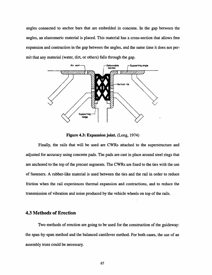
angles connected to anchor bars that are embedded in concrete. In the gap between the
angles, an elastomeric material is placed. This material has a cross-section that allows free
expansion and contraction in the gap between the angles, and the same time it does not per-
mit that any material (water, dirt, or others) falls through the gap.
Air vent r-Deformable rSupporting ongleSsection
Vertical rib
Supporting--ledge
Figure 4.3: Expansion joint. (Long, 1974)
Finally, the rails that will be used are CWRs attached to the superstructure and
adjusted for accuracy using concrete pads. The pads are cast in place around steel rings that
are anchored to the top of the precast segments. The CWRs are fixed to the ties with the use
of fasteners. A rubber-like material is used between the ties and the rail in order to reduce
friction when the rail experiences thermal expansion and contractions, and to reduce the
transmission of vibration and noise produced by the vehicle wheels on top of the rails.
4.3 Methods of Erection
Two methods of erection are going to be used for the construction of the guideway:
the span-by-span method and the balanced cantilever method. For both cases, the use of an
assembly truss could be necessary.
The span-by-span method can be used whenever the span length can be covered
with the assembly truss. As described in the Tren Urbano Fixed Facilities Category II Draw-
ings (Tren Urbano and GMAEC, 1996), the erection of a segment with the span-by-span
method is done in three phases (Figure 4.4). They are:
1. Segment Placementa. After the previous span has been completed, the truss has been advanced and placed
between two piers to construct the next span.
b. The precast segments are delivered by truck and loaded onto the assembly truss withthe use of a ground based crane.
c. After all the segments have been loaded on the truss, the grade and alignment of eachsegment is adjusted, leaving a gap between each segment for the application of epoxy.
2. Epoxy Joining and Stressing of Longitudinal Tendonsa. In a typical span, there are eleven segments between the joint segment and the pier
segment, segments one through three are named section 1, segments five throughseven are named section 2, and segments nine through eleven are named section 3.Segments four and eight are where the deviation ribs are located. The deviation ribsare used to change the trajectory of the post-tensioning tendons through the span. Foreach of the sections 1,2, and 3, epoxy is applied between the segments, and the seg-ments are stressed together with temporary post-tensioning bars.
b. Polyethylene ducts are positioned between the expansion joint segment, the pier seg-ment, and the deviation ribs.
c. Longitudinal post-tensioning tendons are installed.
d. Concrete joints are placed in closure joints.
e. Selected tendons are stressed in both webs simultaneously to approximately 10% ofthe final stressing force.
f. Closure joints are poured.g. After closure joints have reached a minimum compressive strength, the tendons are
stressed simultaneously to their final force.
h. The completed span is lowered onto the bearings.
3. Truss Advancementa. A truss support bracket (used to support the assembly truss) is positioned at the next
pier.

b. The assembly truss is advanced to the next pier.
c. Phases 1 and 2 are repeated to assemble a new span.
Assembly Trss-%
-Truss Support Bracket
Section 1 Section 2 Section 3 Assembly TrSS
Truss support Bracket
/-Assembly Truss
Truss Support racket
Figure 4.4: Span-by-span method. (Tren Urbano and GMAEC, 1996)
When the balanced cantilever method is used (Figure 4.5), it is mostly because a
span can not be constructed with the assembly truss. Following is an example of how the
balanced cantilever method can be used in the erection of a span A, located between piers A
and B, which is next to a span B between piers B and C. Span A is too long to be con-
structed with the span-by-span method. The procedure is presented in five phases:

Span A
Pier A
TempomTempora
Span B
Pier B Pier CPMSE 1
Span B
iry Pier Pier Pier CPHASE 2
"i..*; ;P . I. .:, . ,. ie I ,,a .-... ... .ii ; .
span A span B
Pier A Temporary Pier Pier 8 " Pier CPIASE 3
Span .A'i Span B
Pier A Temporary Pier Pier B .= -Pier CP*OSC 4
Span A
Pier A
Span B
Pier B L Ja Pier CPHASE 5
Figure 4.5: Balanced cantilever method. (Tren Urbano and GMAEC, 1996)
1. Using the assembly truss to support the segments for span B, a balanced cantilever isconstructed at pier B toward pier A.
2. A temporary pier is constructed for span A.
Pier A
___ ,,~,s;-n ICI

3. The assembly truss is placed between pier A and the temporary pier.
4. The remaining portion of span A is constructed with the span-by-span method.
5. Continuity post-tensioning is stressed, cast-in-place joint are made, and the temporarypier is removed.
4.4 Loads and Forces
According to the Tren Urbano Design Criteria (United States Department of Trans-
portation, 1996), in the design of the Tren Urbano structures, the following loads and forces
shall be considered:
1. Dead loads (DL):
Dead loads include the actual weight of the structure and other permanently
installed fixtures such as track-work, acoustical barrier, and emergency walkway. Also
needed here to be considered are the loads to which the structure is subjected during its
erection.
2. Live loads (LL), including rail vehicle (RV), and maintenance rail crane car (RC):
A train in the Tren Urbano will consist of 1, 2, or 3 pairs of rail vehicles. One rail
vehicle has four axles (Figure 4.6). The weight of each axle shall be taken as 146 kN (this
includes the weight of the vehicle and its passengers). It has to be taken into consideration
the possibility of one train pushing or pulling a failed train. The guideway has to be
designed for any train combination that produces the most critical condition.
The guideway has to be designed for one rail crane car on one track at a time. It has
four axles, each weighing 134 kN.

22 785
584 kN
o0 oI 00 010-' L .2085 TO 2310
320C T32o 16 460 TO 15 850 3209, 320._i TO To TOTO' T3505 3505 22860 3505 1 3505
Figure 4.6: Rail vehicle. (USDOT, et al., 1996)
3. Derailment loads (DR):
These loads are produced in the case the derailing of a train occurs. It includes verti-
cal derailment loads, and horizontal derailment loads.
Vertical derailment loads shall be produced by fully loaded vehicles placed with
their longitudinal axes parallel to the track. The lateral vehicle excursion shall vary from
100 to 900 millimeters maximum for tangent track and for curved track with radii greater
than 1.5 kilometers. A vertical impact factor of 100 percent of vehicle weight shall be
applied in computing the equivalent static derailment load. When designing a dual track
guideway, only one train on the track shall be considered to have derailed, while the other
track is loaded with a stationary train.
For cross-sections having clearance between vehicle and barrier wall of 150 milli-
meters to 900 millimeters, with maximum vehicle speed of 88 kilometers per hour, the hor-
izontal derailment force shall be taken as 40 percent of a single fully loaded vehicle acting
600 millimeters above the top of the rail and normal to the barrier wall for a distance of 3
meters along the wall.
4. Earthquake force (EQ):
The guideway has to be designed in accordance with Division I-A, Seismic Design
of the 15th Edition of the AASHTO Standard Specification for Highway Bridges. The fol-
lowing parameters have to be used:
Acceleration Coefficient A = 0.2
Importance Factor IF = 1.25
5. Impact (I), including vertical impact (VI) and horizontal impact (IH):
Impact loads are statically equivalent dynamic loads resulting from the vertical and
horizontal acceleration of the life load. Vertical impact is taken as 30 percent of the rail
vehicle or of the rail crane car. The horizontal impact is taken as 10 percent.
6. Centrifugal force (CF):
These are the forces that are produced by the train on the superstructure when the
superstructure is curved. The centrifugal force shall be taken as a horizontal radial force
equal to the percentage C of the live load. C is calculated with the formula:
S2
C=1.27R
where:
S = design speed in kilometers per hour,
R = the radius of the curve of the track centerline in meters.
7. Longitudinal force (LF):
These forces are produced by the acceleration and the deceleration of the train. They
are applied as uniformly distributed load over the length of the train in a horizontal plane at
the top of the low rail. It is calculated as 28 percent of the live load for decelerating trains,
and 14 percent of the live load for accelerating trains. It must be taken into consideration

possible combinations of acceleration and deceleration where the guideway has more than
one track.
8. Hunting force (HF):
This force is caused by the lateral interaction of the vehicle and the guideway due to
the oscillation of the vehicle back and forth between rails. It is applied at the top of the rail
head, at the lead axle of the train only, and its magnitude its taken as 12.5 percent of the live
load.
9. Rolling force (RF):
It is taken as 10 percent of the live load per track, with a force applied upwards in
one track and downwards on the other track.
10. Earth pressure (E):
This load is applied to structures that retain earth. Consideration shall be given for
side pressure due to earth abutting against the retaining structure and load surcharges resting
on abutting earth, as according to the AASHTO Standard Specification for Highway
Bridges.
11. Hydrostatic pressure and buoyancy (B):
For this loads, the effects of hydrostatic pressure and buoyancy are considered
whenever the presence of groundwater is indicated. Possible changes in groundwater eleva-
tion shall be taken into consideration.
12. Wind load on structure (W):
The guideway has to be designed to withstand wind loads of uniform pressure acting
on the superstructure and the substructure. For the superstructure, if H is taken as the eleva-
tion of the underside of the main girder above the mean retarding surface, then:

H = 0 to 12 meters Transverse wind pressure = 3.6 kN/m 2
Longitudinal wind pressure = 0.9 kN/m2
H = 12 to 18 meters Transverse wind pressure = 4.0 kN/m 2
Longitudinal wind pressure = 1.0 kN/m2
H = 18 to 30 meters Transverse wind pressure = 4.4 kN/m 2
Longitudinal wind pressure = 1.1 kN/m2
The substructure shall be designed to withstand the preceding loads applied to the
superstructure as they are transmitted to the substructure, including the bearings. Also, an
upward linear load shall be applied at the windward quarter point of the transverse width of
the superstructure. Its intensity will be equal to 1.4 kN/m 2 of the exposed plan area of the
deck and the walkway.
13. Wind load on live load (WL):
The guideway has to be designed for the effects caused by the wind load acting on
the life load while the train is operating on top of the guideway. If H is taken as the elevation
of the underside of the main girder above the mean retarding surface, then the loads acting
on the train are taken as:
H = 0 to 12 meters Transverse wind pressure = 2.4 kN/m2
Longitudinal wind pressure = 0.6 kN/m2
H = 12 to 18 meters Transverse wind pressure = 2.7 kN/m2
Longitudinal wind pressure = 0.7 kN/m2
H = 18 to 30 meters Transverse wind pressure = 2.9 kN/m2
Longitudinal wind pressure = 0.7 kN/m 2
For the case of the guideway being dual track, the loads shall be increased 30 per-
cent when both tracks are loaded, in order to account for the shielding effect of vehicle-on-
vehicle as the two trains run alongside each other.

14. Stream flow pressure and flooding (SF):
These loads take into consideration the loads applied to the structures in the case of
flooding.Anticipated flood elevations shall be determined by a study of official flood
records. These loads have to be applied to the guideway as applicable.
15. Creep and Shrinkage forces (R+S):
The stresses and loads caused by the creep and shrinkage of the concrete have to be
considered in accordance with the AASHTO code.
16. Thermal force (T):
The stresses and deformations produced by changes in temperatures have to be con-
sidered in the design. The changes in temperature have to be taken above or below 26 OC.
For concrete, it has to be considered a temperature rise of 11 OC, a temperature fall of 11 OC,
and a coefficient of thermal expansion of 0.000011 per OC. In addition, a differential tem-
perature between the top and the bottom of the box girder has to be considered. The top part
of the box girder will be assumed warmer than the bottom. The differential is taken as 0 OC
at the bottom and as either 10 OC or 5 OC at the top depending on if the thermal load is only
to the dead load, or added to both the dead and live load, respectively.
For the direct fixation track, the controlled setting temperature will be between 27
OC and 32 OC, and it will be considered a temperature rise of 28 OC maximum, a temperature
fall of 17 OC maximum, and a coefficient of thermal expansion of 0.000012 per oC. Provi-
sions shall be made for transverse and longitudinal forces due to temperature variations in
the rail. These loads shall be applied in a horizontal plane at the top of the low rail as fol-
lows:

- Transverse Force
205kNT-R
where R is the radius of curvature of the guideway in meters.
- Longitudinal Force
T = 0.65 xP xL
where P is the longitudinal restraint force per meter (30 kN/m), and L is the
effective length for longitudinal force calculation in meters. For curved track,
L is measured along the curve. In this case, T can not be taken larger than 890
kN.
Wherever a continuous welded rail is terminated, provisions shall be made to fully
restrain its end. This restrain shall be taken as 734 kN based on a 28 OC.
17. Forces due to rail fracture (RB):
For the direct fixation track, horizontal forces resulting from rail break shall be taken
into consideration. Only the break of one rail at a time shall be considered.
18. Differential settlement (DS):
The possibility of differential settlements occurring in a foundation has to be taken
into consideration, and the guideway has to be designed for the stresses and displacement
that such settlement will produce. The foundations have to be designed in such a way that
for girder spans up to 45 meters do not have differential settlements larger than 6 millime-
ters.
19. Collision loads (CL):
Piers or other guideway support elements that are situated less than 3 meters from
the edge of an adjacent street or highway shall be designed to withstand a horizontal static
force of 1 MN, unless it is protected by suitable barriers. This force shall be applied at an
angle of 10 degrees from the direction of the road traffic, and at a height of 1.2 meters above
ground level.
4.5 Possible Sources of Problems
As mentioned before, expansion joints have always been a source of problems in
bridges, not only in Puerto Rico, but also in the rest of the world. To know what to expect
we turn to Beneda and McKenna, whom in 1997 wrote about the aerial structure of the Met-
ropolitan Atlanta Rapid Transit Authority (MARTA), a structure very similar to Tren
Urbano:
"Almost everyone involved in the design, construction and maintenance of bridges
knows that there is no perfect expansion joint seal. Failure of these joint seals dumps water
directly onto the bearings, anchor bolts and substructure below where it can eventually
cause critical problems. Replacement of the joint seals is very expensive, especially for
transit structures. Costs are escalated because the work must be done in the trackway".
The joints being considered for the Bayam6n contract have consistently failed in
highway bridges in Puerto Rico. The major reason for failure is that at the time of installa-
tion, air voids form in the concrete under the edge-protection angles. With air under the
angles, the angles give away, and the elastomeric material between the angles gets taken out
of place. Another common reason is that the elastomeric seal is not placed correctly, and it
gets hit by the vehicle wheels.
Bearings usually are not a source of problems unless expansion joints do not present
any problem. In the case expansion joints fail, the metal support of the bearing could cor-
rode, and then replacement would be needed.

Beneda and McKenna (1997) reported having mixed results with elastomeric bear-
ings on MARTA. Many of the original bearings are still in use, but others have been
replaced. From the writing it is deduced that the damage to bearings could have been pre-
vented with proper design, manufacturing, and construction procedures.
Problems with expansion joints and bearings could be reduced by increasing the
continuity of the guideway. The more continuous the guideway is, the less the number of
expansion joints and bearings is. Still, reducing these sources of problems is not as easy as
increasing continuity. By increasing continuity, other problems get magnified, such as loads
produced by the creep and shrinkage of the concrete. Yet, the most interesting problem that
could come up with increasing the continuity of the superstructure is the thermal forces that
would develop in both the girder and the CWR, and how these forces would interact.

80

Chapter 5
Structural Analysis
5.1 Improvements Through Continuity
In Chapter 3, the complex relationship between the four objectives in bridge design
was presented. It was also presented how these objectives affect certain design decisions of
continuity, expansion joints and bearings. The accomplishment of the four objectives gets
more complicated when it is realized that the three before mentioned design decisions are
themselves interrelated. When the continuity of a bridge or guideway is increased, the num-
ber of expansion joints and bearings needed is generally reduced. Therefore, increasing or
decreasing continuity of a bridge or guideway will have a complex impact that needs to be
considered.
To study the impact of changing continuity in the Tren Urbano superstructure, two
models of a bridge were developed. One model was used to analyze the effects of the dead
loads, live loads, and seismic loads. The other models were used to analyze creep, shrink-
age, and thermal effects.
The dimensions of the models are those of a typical single track section of the guide-
way for the Tren Urbano Project. Typical means that there is no actual section of the Project
that has the exact arrangement and dimensions that the models have, but they do have what
would be found on the average. It is made out of six spans, each of 36 meters long. These
six spans are made of two-span-continuous units, for a total of three units
Besides these models for the two-span-continuous structure, three other pairs of
models were developed. In each of pair, the continuity was changed, but the number of

spans and the span length remained unchanged. These other three models developed are:
* a design in which the spans are simply supported,* a design made out of three-span-continuous, and* a design made out of two units, a four span-continuous with a two span continuous. This
structure will be refer to from now on as the four-span-continuous structure.
Each of the eight models developed were analyzed using the program SAP2000, a finite ele-
ment and structural analysis computer program.
For each pair of models, the results were combined. With these final results, the
structural behavior of the four arrangements is predicted, providing a basis for comparison
to define how the structural behavior gets affected with changes in continuity.
5.2 SAP2000
SAP2000 is the latest version of the series of SAP programs developed by Comput-
ers and Structures, Inc. (CSI). This series of programs is for use in the analysis and design
of structures. The previous version of this series, SAP90, was used in the design process of
the Bayam6n contract by the consortium headed by company ICA, that includes the compa-
nies Euro Estudios and Stone & Webster Engineering Corporation. This consortium is the
design/build contractor for the Bayam6n contract.
Using SAP2000, a structure can be analyzed and designed by creating a model using
the program's graphical user interface. The model can include the structure's properties,
such as material properties, connections, and restraints. Loads can be applied to the model
and the program provides results of the analysis including displacements, stresses, and reac-
tions in the structure.
The use SAP2000 in this research, instead of SAP90, is a matter of the newer ver-
sion being available to the author. SAP2000 is also more user friendly and has other modifi-

cations that SAP90 does not have (CSI, 1997). Still, these modifications are of no
importance to this research, because the models used to analyze the dead loads, live loads,
and seismic loads for this research are mostly based on the modeling done by ICA using
SAP90. Using the same model in SAP2000 and SAP90 will still provide the same results.
5.3 Description of Models
The model analyzed in this research is based a precast prestressed segmental con-
crete rail transit bridge supported on spread footings with a single track. It consist of six
spans with abutments at the end. Four different span configurations were studied for the
bridge. For each span configuration, two models were used.
5.3.1 Model for Analysis of Dead Loads, Live Loads, and Seismic Loads
The first model (Figure 5.1) developed for each span configuration is mostly based
on the model used by the consortium headed by ICA in the design of the Bayam6n contract.
This first model was used to study the effects in the structure due to dead loads (including
prestressing), live loads, and earthquake loads.
In the Tren Urbano Fixed Facilities Category I Contract Drawings (Tren Urbano and
GMAEC, 1996), it is shown that the guideway for the project will be mostly composed of
two-span-continuous units, and that each span will normally be of 36 meters in length.
Therefore, the reinforced concrete columns in all models were spaced 36 meters apart.
There where two columns sizes taken: a column with diameter of 1.83 meters and a height
of 5.9 meters, and another with diameter of 2.135 meters and a height of 6 meters. The col-
umn with the smaller dimensions is used to model the expansion joint pier. It has a slightly

shorter height to allow the placement of elastomeric bearings, while keeping the superstruc-
ture at constant height.
These columns dimensions were taken from the model developed by the consortium
involving ICA, because this columns have been proven to support the loads sustained dur-
ing the construction of the guideway by the span-by-span erection method. These should
not change, no matter what span configuration is built. Therefore, the loads can be ignored
from the analysis.
Each column is modeled with one frame element. Isotropic material properties are
given, meaning that the material properties are independent of the direction of loading or of
the orientation of the material. Isotropic behavior is usually assumed for steel and concrete
(CSI, 1997). The columns were given the properties of concrete with a strength of f'c = 28
MPa (4000 psi). These properties are a density of 0.6 kg/m3 , unit weight of 5.866 kN/m3, a
modulus of elasticity of 23.42x10⁶ kN/m2 , and a Poisson's ratio of 0.25.
Figure 5.1: Model of two-span-continuous design for dead loads, live loadsand earthquake loads.

The bottom node of each column was restricted of all movements and rotations. This
is done assuming that the interaction between the spread footing and the soil behaves very
closely to them being rigidly attach.
On top of the columns in which the guideway is not continuous, frame elements are
used to represent rigid links and bearings (Figure5.2). Rigid links are members used to sim-
ulate the connection between the beams and the bearings, and between the bearings and the
columns. Naming these elements rigid links means that they are given such properties that
their stiffness is very high, therefore the elements do not suffer any deformation. Having
rigid links permit the modeling of two bearings for one end of a beam unit.
bearing
rigid links
column
bearing
Figure 5.2: Expansion column model.
The elastomeric bearings are modeled as frame elements arranged vertically, with a
length of 10 centimeters. This length of the frame element is what would be the bearing
thickness. The cross-section size given to this element are the bearing's dimensions of width
and length. All bearings have the same shear modulus of 1400 kPa, but each bearing's elas-
tic modulus will depend on its dimensions. Details on how the bearing properties were
obtained are presented in Appendix C.
To model the abutments, the same kind of rigid link configuration with bearings that
was used for expansion piers was used. The joints at each end of the structure (that is part of
this configuration) is restricted for all movements, same as it was assumed for the spread
footings.
Four types of frame elements were used to model the precast segments. The types
One and Two are used to model the joint segment, each type represents one of the joint seg-
ment's two different cross sections. The type Three is used to model the typical segments.
One Type Three element represents one typical segment. Type Four is used to model the
pier segment. Two Type four elements are used to model one pier segment. This is to allow
the rigid connection of the pier segment and the column to occur at the mid-length of the
segment. Each type was given the corresponding properties of the cross-section they repre-
sent.
Consecutive elements representing consecutive precast segments share one joint.
Eleven typical elements were placed in each of the model six spans. The number of ele-
ments used to represent pier segments and expansion segments depend on the span configu-
ration of the structure. All frame elements representing precast segments where given
isotropic material properties corresponding to concrete of strength of f'c = 35 MPa (5000

psi). These properties are a density of 2.4 kg/m3, a unit weight of 23.544 kN/m3 , a modulus
of elasticity of 27.67x10⁶ kN/m2, a Poisson's ratio of 0.30.
5.3.2 Model for Analysis of Creep, Shrinkage, and Thermal Effects
The second model is a two-dimensional (Figure 5.3). It was use to model the effects
of creep, shrinkage, and changes in temperature.
Figure 5.3: Model of two-span-continuous design for creep, shrinkage,and temperature effects.
The modeling of the columns is done in the same way that it was done for the first
model. A change made from one model to the other is that only one rigid link is used to con-
nect expansion joint piers with the elastomeric bearing, but each rigid link is modeled with
ten frame elements, to model the rail superstructure/interaction, as it will be explained later
in this section. The joint of each rigid link at the each end of this structure is restricted from
all movements, to account for the abutments. Also, only one frame element is used to model
a pair of bearings. The cross sectional properties of the bearing models were adjusted to do
SO.
I I I I I

A critical subject in the modeling, in order to perform a successful analysis of the
effects of creep, shrinkage, and temperature changes, is representing the superstructure/rail
interaction. Fryba (1996) suggested that the connection between the CWRs and the super-
structure is idealized by a system of infinitely close horizontal springs. Fryba offers typical
values to be taken for the stiffness per unit length of the horizontal spring (Figure 5.4). For
prestressed concrete bridge directly fixed to the structure (without ballast), a stiffness per
unit length of 8 N mm-2 is suggested.
t 12
Figure 5.4: Idealization of the rail/superstructure interaction. (Fryba, 1996)
First, to model the superstructure/rail interaction for this research, the beams were
modeled with the same four types of frame elements used in the first model, but this time,
ten elements were used where only one element was used in the first model. Also, another
property was added to the frame elements representing the segments: a coefficient of ther-
mal expansion of 11x10 -6 per Celsius degree.
rail
bearinghorizontal spring
superstructure column model
Figure 5.5: Modeling of rail/superstructure interaction using SAP2000.

Second, on top of each frame element that represents either the superstructure or a
rigid link, a corresponding new frame element of the same length was place parallel at an
arbitrary chosen distance of 40 cm from the superstructure, and a distance of 50 cm of the
rigid links (which are located 10 cm below the superstructure). These new frame elements
represent the rails. The area and the moment of inertia of each of this elements is that of the
double of a typical 115 RE as specified by the American Railway Engineering Association
(AREA). Also, typical properties for the rails were given: a modulus of Elasticity of
2.1x10 5 MPa, a Poisson's ratio of 0.30, and a coefficient of thermal expansion of 12x10 -6 /
OC. Both ends of the rail were restricted of all displacements.
Finally, the infinitely horizontal springs were modeled with vertical frame elements
(Figure 5.5), connecting each of the joints of the rigid links and the superstructure to a cor-
responding joint of the rail directly on top. In order for them to act as a horizontal spring, a
large area was given to each the vertical elements, so that they act as bending beams. Then
the properties of the vertical element were fixed so that the beam acts as a horizontal spring
of stiffness per unit length of 8 N mm"2. This is done by equating:
12 x Elkxs-h3
where:
k = the stiffness per unit length of the horizontal spring;
s = distance between vertical elements;
E = modulus of elasticity for the vertical elements;
I = moment of inertia of the vertical element;
h = height of the vertical element.

The value of k is given, and the values of s and h are defined by the geometry of this
model. An arbitrary value of E of 8 N mm-2 was chosen, and it was solved for I, assigning
this value to the vertical element this result.
5.4 Modeling of Loads
As mentioned before, for each span arrangement, two models were developed using
SAP2000. For the first model, the loads included in this analysis are dead loads (including
prestressing), live loads (specifically, loads caused by the train, including vertical impact),
and earthquake loads. Loads caused by creep, shrinkage, and temperature changes are ana-
lyzed in the second model. The results of the analysis of each corresponding pair of models
are added to determine how a span arrangement will work.
Other loads could be part of the analysis (like wind loads), but they are not going to
be considered here. This is done because by experience, the load combination that will
determine the design of the elements when using either, Service Load Design or Load Fac-
tor Design, of a bridge with such a small height as this one, located in a Seismic Zone 3 is:
Group VIII= DL+LL +IV +B +SF+E +EQ
For the case analyzed here, B, SF and E are equal to zero. (Refer to Section 4.4 for load def-
initions). EQ has to be analyzed in both the transversal and longitudinal direction of the
structure. The one that produces the most critical loading is used in the design procedure.
Also, its written in the Tren Urbano Design Criteria (United States Department of Transpor-
tation, et al., 1996): "The permanent effect of creep (R) and shrinkage (R) shall be added to
all service load and load factor design group loading combinations with a load factor of
1.0".

5.4.1 Dead Loads
The dead loads include the weight of the beams, columns, pier caps for the columns
with bearings on top, the acoustical barrier, and the emergency walkway. The weight of the
beams and columns were assigned with the material properties for its frame elements. The
weight of the pier caps is represented as a concentrated load of 421.44 kN acting downward
on top of columns with pier caps. The weight of the acoustical barrier and the emergency
walkway is represented as a distributed load on top of the precast segments of 39.127 kN/m,
as calculated by the consortium headed by ICA.
Also included in the dead loads are the prestressing loads. These loads are difficult
to model, so assumptions were taken to simplify the analysis.
The major assumption made was that the each span is prestressed with just one ten-
don placed inside the beam with a parabolic profile and tensioned at the center of gravity of
the beam cross-section. In reality, at least eight tendons are used to prestress one span. This
simplification allows the modeling of the prestress with equivalent loads.
With the simplification, a prestressing force P is chosen. The effects of this load are
model with equivalent loads. Theses are two downward loads at each end of the span, a hor-
izontal load acting in compression at each end of the span, and a distributed load acting
upward (Figure 5.6). The magnitude of the downward load is P sine and the magnitude of
the horizontal load is P cose, where 0 is the angle from the horizontal plane at which the
prestressing load acts. This angle was estimated from Tren Urbano drawings (Tren Urbano
and et al., 1986) as being 5.86 degrees.
To calculate the distributed load, the following equation is used:
w12
Pe=8

where:
P = the prestressing force;
e = the eccentricity of the tendon from the center of gravity of the beam cross-
section at the center of the beam.;
I = the beam length;
w = the equivalent distributed load produced by the prestressing.
Psin 8 Psin 8
P cos 8
Figure 5.6: Equivalent loads for prestressing. (Nilson and Winter, 1987).
In the above equation, P is given, I is known, and e is estimated from drawings to be
1.07 meters. The equation is solved for w and this result is included in the loading of the
model.
5.4.2 Live Loads
The effects of the live load is represented by performing a Bridge Analysis with the
program SAP2000. First, the track of the train is modeled by specifying a lane on top of the
precast segments, and on top of the rigid links aligned with the models of the segments.
Second, three kinds of Vehicles were defined. The first is made out of one pair of
Rail Vehicles (RV), the second is made with two pairs of RV's, and the third one is com-
posed of three pairs. Each RV has four axles, weighing each 146 kN. The separation
between axes were taken from the Tren Urbano Design Criteria (United States Department
of Transportation, et al., 1996), and are shown in Figure 4.6. The axle load given is taken by
the program as a maximum value, meaning that SAP2000 will change this value, trying to
find the most critical response of the structure. This is done to take into account for cases in
which the train is not fully loaded (CSI, 1997). The Rail Crane Car (RC) is not included in
this analysis because it has a lower weight than the Rail Vehicle.
Third, a Vehicle Class including the three modeled vehicles was defined, and finally,
a Moving Load case was also defined. SAP2000 performs the analysis by taking all the
assignments in a Moving Load case, trying every possible permutation of loading. The pro-
gram gives as a result the maximum and minimum response quantities for the permutations
of a Moving Load case as permitted by vehicle and lane assignments (CSI, 1997).
To include the effects of the vertical impact, as scale factor of 1.30 was assigned to
the Moving Load case. This adds 30% to the live load, the specified load for the vertical
impact.
5.4.3 Earthquake Loads
To perform the seismic analysis, the program SAP2000 uses the masses specified in
the different elements of the model. By specifying density for the columns and precast seg-
ments, the program calculates lumped masses for the joints in the model. To account for the
emergency walkway and the noise barrier, a distributed mass of 399 kg/m was added to the
precast elements. To account for the piercaps, a mass of 429.6 kg was assigned to the top
node of each column with a pier cap.
The response spectrum used for this analysis was calculated according to AASHTO
(1996), using an acceleration coefficient of A = 0.2, a soil type II, and a structure impor-
tance factor of 1 (Figure 5.7). The response spectrum was inputted in SAP2000. The analy-
sis is performed twice, first applying seismic forces in the transversal direction of the
bridge, and then in the longitudinal direction.

~0.6
E 0.5
~ 0.4-
0.3
0.2
0.1
U) 0 , , ,
0 0.5 1 1.5 2 2.5
Period (seconds)
Figure 5.7: Response spectrum. (Euro Estudios, 1997)
The program performs a modal analysis after a 5 percent damping was assigned to
each mode. SAP2000 solves for each mode performing an eigenvector analysis.
5.4.4 Creep and Shrinkage
Creep and shrinkage are going to produce a shortening of the beams in the structure.
The Precast/Prestressed Concrete Institute (1992) offers a procedure to approximate the
strain shortening due to these time dependent effects. Knowing that the design temperature
change for Tren Urbano is 220C, and that the average ambient relative humidity is 78%, cal-
culations were performed using the PCI procedures, for different spans configurations. For
all calculations, the total strain due to creep and shrinkage fell between 4.5x10 -4 and 5x10⁻⁴.
Using SAP2000, strains can not be included in an analysis directly. Indirectly, these
effects can be accounted for by representing them as an equivalent temperature drop. This is
done by equating:

aATL = EL
where:
a = coefficient of thermal expansion
AT = temperature change
L = length of the beam
E = strain due to creep and shrinkage.
Taking a strain of 5x10 -4, and the thermal coefficient of concrete, it is solve for the
change in temperature. A result of 450 C was obtained and used for all models.
5.4.5 Temperature Effects
The first step in modeling temperature loads was assigning a reference temperature
to the frame elements representing the precast segments and the CWRs. This temperature,
as specified in the Tren Urbano Design Criteria, is 26 OC for the precast segments, and
between 270C and 32 0C (it does not matter what temperature is chosen for the steel).
Then, a temperature drop of 110C is added to the equivalent temperature fall calcu-
lated for the precast segments to account for creep and shrinkage. For the steel, a drop of
170C is assigned. Also, a gradient of 100C is assigned to the concrete segments to account
for the top slab getting warmer than the bottom slab. A temperature drop was assigned in
this analysis, because it will make the effects of creep and shrinkage more critical than a
temperature rise.

5.5 Analysis Process
After the input for SAP2000 have been prepared with the model and the loading, the
program was run. With the results provided by the program, the maximum shear deforma-
tion of the bearings due to the most critical combination of loads (dead load, live load, ver-
tical impact, creep, shrinkage, temperature effects, and either a longitudinal or a transversal
earthquake) was checked. AASHTO limits this deformation to one half the bearing thick-
ness. Therefore it was checked that the bearings would not deform more that 5 cm. Sizes of
the bearings were adjusted to comply with this specification.
After a satisfactory bearing size has been found, the program was run again. After
the results were obtained, the stresses occurring in the precast segments were checked. It is
desirable that the concrete is always in compression, so the prestressing force was adjusted
trying to reduce to a minimum the tensile forces in the superstructure. When an optimum in
prestressing forces was found, the reinforcing steel (with yield strength of fy = 60 ksi) nec-
essary to account for tensile forces in the superstructure was calculated.
Then, the stresses occurring in the rail were checked. This stresses were obtained
from the analysis of the model used for creep, shrinkage, and thermal effects, and by per-
forming a simple calculation to determine the effects of the live load on the rail. More
details on these calculations are presented in Appendix G.
Later, the loads acting on the elements representing the columns were used to find
the reinforcement that is going to be needed for the columns. Details of the design of rein-
forcement for the columns are presented in Appendix D.
Finally, the loads at the bottom of the columns were used to design spread footings.
It was assumed that the soil on which the foundation is built is leveled all through the length
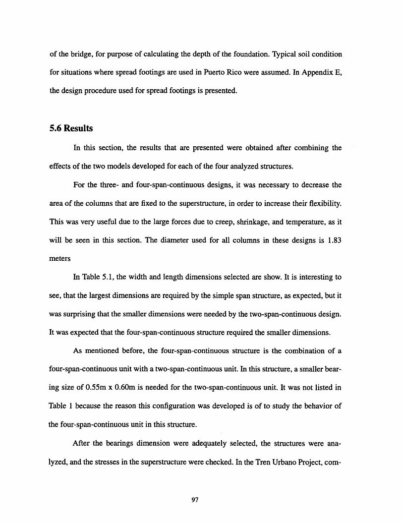
of the bridge, for purpose of calculating the depth of the foundation. Typical soil condition
for situations where spread footings are used in Puerto Rico were assumed. In Appendix E,
the design procedure used for spread footings is presented.
5.6 Results
In this section, the results that are presented were obtained after combining the
effects of the two models developed for each of the four analyzed structures.
For the three- and four-span-continuous designs, it was necessary to decrease the
area of the columns that are fixed to the superstructure, in order to increase their flexibility.
This was very useful due to the large forces due to creep, shrinkage, and temperature, as it
will be seen in this section. The diameter used for all columns in these designs is 1.83
meters
In Table 5.1, the width and length dimensions selected are show. It is interesting to
see, that the largest dimensions are required by the simple span structure, as expected, but it
was surprising that the smaller dimensions were needed by the two-span-continuous design.
It was expected that the four-span-continuous structure required the smaller dimensions.
As mentioned before, the four-span-continuous structure is the combination of a
four-span-continuous unit with a two-span-continuous unit. In this structure, a smaller bear-
ing size of 0.55m x 0.60m is needed for the two-span-continuous unit. It was not listed in
Table 1 because the reason this configuration was developed is of to study the behavior of
the four-span-continuous unit in this structure.
After the bearings dimension were adequately selected, the structures were ana-
lyzed, and the stresses in the superstructure were checked. In the Tren Urbano Project, com-
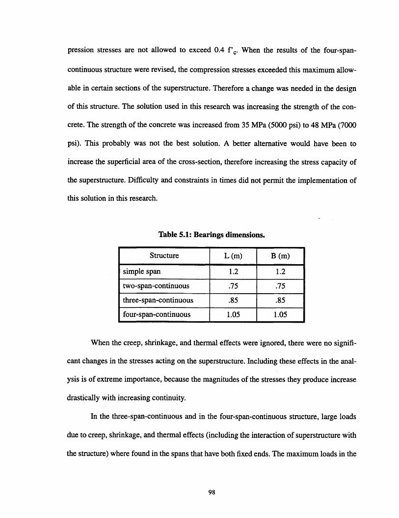
pression stresses are not allowed to exceed 0.4 f'c. When the results of the four-span-
continuous structure were revised, the compression stresses exceeded this maximum allow-
able in certain sections of the superstructure. Therefore a change was needed in the design
of this structure. The solution used in this research was increasing the strength of the con-
crete. The strength of the concrete was increased from 35 MPa (5000 psi) to 48 MPa (7000
psi). This probably was not the best solution. A better alternative would have been to
increase the superficial area of the cross-section, therefore increasing the stress capacity of
the superstructure. Difficulty and constraints in times did not permit the implementation of
this solution in this research.
Table 5.1: Bearings dimensions.
Structure L (m) B (m)
simple span 1.2 1.2
two-span-continuous .75 .75
three-span-continuous .85 .85
four-span-continuous 1.05 1.05
When the creep, shrinkage, and thermal effects were ignored, there were no signifi-
cant changes in the stresses acting on the superstructure. Including these effects in the anal-
ysis is of extreme importance, because the magnitudes of the stresses they produce increase
drastically with increasing continuity.
In the three-span-continuous and in the four-span-continuous structure, large loads
due to creep, shrinkage, and thermal effects (including the interaction of superstructure with
the structure) where found in the spans that have both fixed ends. The maximum loads in the

superstructure due to creep, shrinkage and temperature effects are shown in Table 5.2.
Notice the drastic increase in loading that occurs from the two-span-continuous to the three-
span-continuous structure.
Table 5.2: Maximum loads in the superstructure due to creep, shrinkageand temperature.
Axial Load MomentStructure(kN) (kN m)
simple span 371 3773
two-span-continuous 271 4198
three-span-continuous 4,211 9,618
four-span-continuous 10,346 20,518
Meanwhile, it can be seen in Table 5.3 that the stresses in the rail practically remain
unaffected with changes in the continuity of the superstructure. This maximum values
shown in here were found in the areas of the rail that are on of expansion piers, where the
end of two beams meet and expand in different directions.
Table 5.3: Maximum stresses in the rail.
Structure Compression Tension(kPa) (kPa)
simple span 219,126 102,888
two-span-continuous 219,256 101,369
three-span-continuous 217,990 102,022
four-span-continuous 218,242 100,537
The prestressing loads P that were applied to the superstructure are shown in Table
5.4. The simple span structure needs a high prestressing load to reduce the deflections of the

beams at midspan. The continuity in the two-span-continuous structure permits the reduc-
tion in prestressing load. In the three-span continuous structure, spans 2 and 5 have fix ends,
as do spans 2 and 3 in the four-span-continuous structure. Creep, shrinkage and thermal
effects required that these spans had their prestressing load increased, although the other
spans of these structures could maintained the lower prestressing loads of the two-span-con-
tinuous structure.
Table 5.4: Applied prestressing load (kN).
Structure Span 1 Span 2 Span 3 Span 4 Span 5 Span 6
simple span 160 160 160 160 160 160
two-span-continuous 130 130 130 130 130 130
three-span-continuous 130 160 130 130 160 130
four-span-continuous 130 160 160 130 130 130
A measure of the reinforcement needed in the columns for each structure is pre-
sented in Table 5.5. It can be seen that the required reinforcement increases drastically for
piers 1, 2, 4, and 5 in the three-span-continuous structure, and in piers 1 and 3 in the four-
span-continuous structure. These piers are rigidly connected to the superstructure. Again,
this drastic increases are due to the large loads produced by creep, shrinkage, and tempera-
ture changes.
Table 5.5: Gross reinforcing ratio of columns.
Structure Pier 1 Pier 2 Pier 3 Pier 4 Pier 5
simple span 0.01 0.01 0.01 0.01 0.01
two-span-continuous 0.01 0.01 0.01 0.01 0.01
three-span-continuous 0.05 0.05 0.01 0.05 0.05
four-span-continuous 0.08 0.01 0.08 0.01 0.01
100
Of course, the higher loads in the columns produce higher loads in the foundations.
In Table 5.6 it can be seen that the required dimensions are larger for the foundation that
support the columns were there was a drastic increase in reinforcement.
Table 5.6: Spread footing dimensions of width and length in meters.
Structure Pier 1 Pier 2 Pier 3 Pier 4 Pier 5
simple span 4x6 4x7 4x7 4x7 4x6
two-span-continuous 6x7 4x4 6x7 4x4 6x7
three-span-continuous 10x5 11x5 3x6 11x5 10x5
four-span-continuous 13x7 1 l1x5 15x5 3x5 6x7

102

Chapter 6
Life-Cycle Costing
6.1 Bridge Economy
A common error made when estimating the cost of a bridge is to include only the
costs of construction, primarily the costs of materials and labor. This error leads to the
design of a bridge with minimum construction costs that fulfills only immediate safety and
serviceability requirements. Usually this is the type of bridge that will need a lot of inspec-
tion, maintenance, and, probably, a major rehabilitation, in order for it to keep fulfilling the
safety and serviceability requirements.
The cost-effectiveness of a bridge can not based only on the construction cost. The
economy of a bridge is best evaluated using the life-cycle cost (Menn, 1990). Life-cycle
cost analysis is defined by the The American Institute of Architects (1977) as any technique
which allows assessment of a given solution or choice among alternative solutions on the
basis of considering all relevant economic consequences over a given period of time (or life-
cycle). In the case of a bridge or guideway, the life-cycle cost should at least include the
costs of construction and operation. Other costs can be included in the analysis, such as
costs of major rehabilitation, and demolition. Brito and Branco's (1994) life-cycle model
(which they called global cost analysis) includes the benefits a bridge provides in offering a
better service for traffic.
Life-cycle cost analysis can be performed during different stages of the construction
process, including planning and design, construction, and operation. It is in the design and
planning phase of a project where the life-cycle cost analysis has the greatest potential to
103

produce savings (Arditi and Messiha, 1996). When the project gets into the construction
and operation phase, it is more difficult to make a change in the bridge that will bring sav-
ings. In addition, these changes at this point are more costly.
The cost of operation includes costs incurred in inspection, maintenance, and reha-
bilitation. When calculating life-cycle cost, operating costs are usually represented as an
equivalent annual expenditure. Usually, as explained before, annual operating expenditures
will be higher for bridges that have been designed solely to minimize construction costs.
Although it seems advantageous to perform a life-cycle cost analysis for the con-
struction of bridges, there are many bridge designers who do not implement this method.
Ignoring life-cycle cost is very common among bridge designers in Puerto Rico, and for that
matter, designers of the Tren Urbano Project. The reasons for this could be (Arditi and
Messiha, 1996):
1. The lack of standards or formal guidelines for the performance of a life-cycle cost anal-ysis.
2. The lack of reliable past data.
3. The disability to determine future costs and factors.
4. Focusing on present costs, and lack of concern for future cost implications.
The second reason is especially true for the Tren Urbano Project, since nothing like
this project has ever been built in Puerto Rico. Still, similar projects have been built in the
United States and in other countries, and many of the private design and construction com-
panies involved have also worked on similar projects.
104

6.2 Effects of Increasing Continuity on the Life-Cycle Cost of a Bridge
As it was seen in Chapter 5, increasing continuity of a bridge design can cause
major changes in the design. Foundations sizes can change, beam cross-sections sizes could
be changed, the amount of reinforcing and prestressing steel could be changed.
The reader must not make the mistake of generalizing the results of Chapter 5 to all
other projects. For example, in this research it was found that the sizes of the spread foot-
ings increased with the increase of bridge continuity. The main reasons for this increase
were the high loads induced by creep, shrinkage and temperature effects. Foundation sizes
do not necessary have to increased in other kind of bridges. For example, it is possible that
the problem of creep and shrinkage could have been avoided by not connecting rigidly the
columns with the superstructure. In any case, the increase in continuity of a bridge or a
guideway will most certainly cause a change in the consumption of materials, which means
a change in the construction costs.
One thing is certain: when continuity is increased, the number of expansion joints
decreases. No expansion joint last forever. Therefore, they need to be inspected and
replaced when damaged. Failure to do so may result in damages to the bridge structure that
could be very costly. It can be safely concluded that with increase in continuity, there is a
reduction in operation costs.
Also, with an increase in continuity, the number of bearings is reduced, depending
on whether the continuous beam units are integral with the columns. It is usually said that if
designed properly, bearings can last the lifetime of the bridge. Still, bearings have failed in
many cases. Therefore, bearings need to be inspected, and sometimes replaced. If bearings
can be reduced through an increase in continuity, operation costs can be further lowered.
105

6.3 Life-Cycle Cost Analysis
In this section, a simplified life-cycle cost analysis is performed for each of the
structures analyzed in Chapter 5. The costs used in the analysis were taken from a list of
costs prepared by the Bridge Department of the Massachusetts Highway Department in
order to estimate the construction costs of a future project. These costs are presented in
Table 6.1.
Table 6.1: Unit costs (Source: Massachusetts Highway Department)
Material Unit Price
Prestressed Concrete Box Beam- f'c=35 MPa $452.13 per surface square foot
Prestressed Concrete Box Beam - f'c-48 MPa $484.42 per surface square foot
Prestressing Steel - ASTM, Grade 270 $38,137.26 per cubic meter
Reinforcing Steel - fy=60 ksi $19,068.63 per cubic meter
Elastomeric Bearings $61,032.68 per cubic meter
Expansion Joints $1,049.92 per linear meter
Concrete - f'c=28 MPa $459.34 per cubic meter
Concrete -f'c=35 MPa $548.83 per cubic meter
Concrete -f'c=35 MPa $548.83 per cubic meter
In the calculation of construction costs for this analysis, labor costs and other mate-
rial costs were not included in the analysis. These costs were ignored because they would be
roughly the same for all four designs. Therefore they will not affect a comparison of costs
between the structures.
First, the cost of the precast segments was calculated. This was obtained by calculat-
ing the total surface area of the top of the superstructure. This cost is only different to the
four-span-continuous structure because a higher strength concrete was used.
106
Second, the cost of prestressing steel was estimated. The tendons to be used, as
specified by the Tren Urbano Design Criteria (United States Department of Transportation,
et al., 1996), are ASTM A416, Grade 270. Their maximum allowable stress at anchorage is
1300 MPa. The area of the tendons required for each structure was obtained by dividing the
prestressing load by the allowable stress. Then, the tendon length needed for each span was
approximated and multiplied by the area to obtain the volume of prestressing steel.
Third, the reinforcing steel area required for the tensile stresses in the precast seg-
ments was considered. It was assumed that the reinforcing bars were going to be placed
through the length of the precast segments, therefore allowing the calculation of the total
steel volume.
Fourth, knowing the bearings dimensions, the volume of each bearing was calcu-
lated. Considering the number of bearings used in each design, the total bearing volume was
calculated for each structure.
Fifth, the number of expansion joints needed for each structure was calculated. By
multiplying this number by the top width of the cross-section of the segments (5.7 meters),
the total expansion joint length was obtained.
Sixth, the total cost of the columns was obtained by computing the required steel
volume of each column and the required concrete volume. By multiplying the required
gross steel ratio (obtained in the analysis presented in Chapter 5) by the gross area of the
column, and then multiplying the result by the height of the column, the steel volume was
estimated. Then, subtracting this volume off the gross column volume, an estimate of the
concrete volume was obtained. For all columns, concrete with f'C = 28 MPa was used,
except for the four-span-continuous structure where concrete with f'c = 35 MPa was used.
107

Finally, costs of the foundations are calculated using the results of the analysis pre-
sented in Chapter 5. With the obtained dimensions, the volume of excavation and the vol-
ume of the concrete needed for the foundation were calculated. For all foundations,
concrete of strength f'c = 28 MPa was used.
In the calculation of operation costs, two assumption were made: all expansion
joints of each structure would need to be replaced every ten years, and half of the bearings
of each structure would be replaced at half the life of the project. The life of Tren Urbano
Project is taken as 50 years. Therefore, it is expected that bearings will be replaced at years
10, 20, 30, and 45 of the project, while half of the bearings will be replaced at year 25.
Each of the maintenance costs were changed into present costs with the equation:
P = F(1 + i) - n
where:
P = present cost;
F = future cost;
i = annual interest rate;
n = year when the future cost takes place.
For the interest rate i, effects of inflation can be considered. Different values of i were used
in the analysis to observe its effect in the maintenance cost.
Finally, the construction costs and the maintenance costs were added to obtain the
total cost of each structure considered.
108
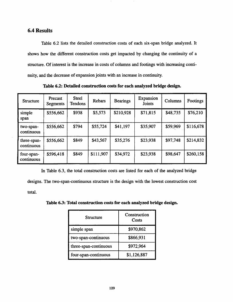
6.4 Results
Table 6.2 lists the detailed construction costs of each six-span bridge analyzed. It
shows how the different construction costs get impacted by changing the continuity of a
structure. Of interest is the increase in costs of columns and footings with increasing conti-
nuity, and the decrease of expansion joints with an increase in continuity.
Table 6.2: Detailed construction costs for each
In Table 6.3, the total construction costs are listed
designs. The two-span-continuous structure is the design
total.
analyzed bridge design.
for each of the analyzed bridge
vith the lowest construction cost
Table 6.3: Total construction costs for each analyzed bridge design.
109
r e Precast Steel ExpansionStructure Precast Steel Rebars Bearings Columns FootingsSegments Tendons Joints
simple $556,662 $938 $5,573 $210,928 $71,815 $48,735 $76,210span
two-span- $556,662 $794 $55,724 $41,197 $35,907 $59,969 $116,678continuous
three-span- $556,662 $849 $43,567 $35,276 $23,938 $97,748 $214,832continuous
four-span- $596,418 $849 $111,907 $34,972 $23,938 $98,647 $260,158continuous
ConstructionStructure
Costs
simple span $970,862
two-span-continuous $866,931
three-span-continuous $972,964
four-span-continuous $1,126,887
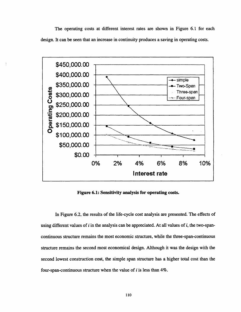
The operating costs at different interest rates are shown in Figure 6.1 for each
design. It can be seen that an increase in continuity produces a saving in operating costs.
Figure 6.1: Sensitivity analysis for operating costs.
In Figure 6.2, the results of the life-cycle cost analysis are presented. The effects of
using different values of i in the analysis can be appreciated. At all values of i, the two-span-
continuous structure remains the most economic structure, while the three-span-continuous
structure remains the second most economical design. Although it was the design with the
second lowest construction cost, the simple span structure has a higher total cost than the
four-span-continuous structure when the value of i is less than 4%.
110

Strictly speaking in economic terms, the two-span-continuous structure turns out to
be the best design. It is the structure that uses both the advantages of continuity, and mini-
mizes the effects of creep, shrinkage, and expansion joints.
Figure 6.2: Sensitivity analysis for life-cycle cost.
$1,600,000.00
$1,400,000.00
., $1,200,000.00
O $1,000,000.00 _-- , . . .'--- ---I i,__
" $800,000.00
S$600,000.00 I-.-Simple.- U-Two-span
$400,000.00-*A'-Three-span
$200,000.00 I-- Four-span
$0.00
0% 2% 4% 6% 8% 10%
Interest rate

112
Chapter 7
Increasing Continuity for Tren Urbano
7.1 Introduction
It has been shown in Chapter 5, that continuity of the guideway design of the
Bayam6n contract of Tren Urbano can be increased to at least three spans, without changing
the strength of the concrete used and the yield strength of the reinforcing steel. Also shown
is that a four-span-continuous unit could be constructed if a higher strength concrete is used,
or different alternatives are considered, like increasing the area of the cross-section of the
precast segments. A different kind of foundation could be considered, such as piles.
Changing the continuity in the Tren Urbano Project would have some impact on the
achievement of the four objectives of bridge design. In this chapter, these effects and their
interrelation are presented.
7.2 Safety
Any design must be safe, no matter what span continuity is adopted. It cannot be
allowed to fail under design loads. Yet, things go wrong and designs can fail. In the event of
there being a failure, the more continuous the structure is, the safer it will be because of its
redundancy.
When using simple spans, if a failure were to occur in the superstructure, there
would be a large deflection at midspan, and the columns would not be able to offer much
resistance to reduce this deflection, and there could be a collapse in the structure. Mean-
while, if the superstructure were continuous, the columns would be able to offer more resis-
113

tance against there being larger deflections. The more continuous the structure is, the more
columns that would be able to act in the resistance against deflections.
Another advantage of redundancy is more protection if a column were to fail. In the
case that simple spans were used, if a column were to collapse, the spans that it supports
would collapse too. In the case of having continuous units, if a column were to collapse,
there is a better chance that the beam or beams that the column supports will not collapse,
because other columns continue to support the continuous unit.
One must not conclude from the discussion presented above that continuous units
are safer for Tren Urbano. It was found in the analysis presented in Chapter 5 that with the
increase in continuity, there are going to be increased stresses in the precast units. Again,
this is due to there being columns monolithic with the continuous units, which in turn
causes the development of stresses due to creep, shrinkage, temperature changes, and rail/
superstructure interaction. Therefore, stresses in the superstructure get closer to the allow-
able stresses with increasing continuity.
7.3 Serviceability
Increasing continuity would definitely be an improvement to the serviceability of
Tren Urbano. The first obvious reason for this is that the number of expansion joints would
be reduced.
Expansion joints have always been a source of problems for bridges. No expansion
joint lasts forever. Therefore they need to be inspected periodically, because an expansion
joint failure, when undetected, can cause damages to the concrete and reinforcing steel of
the beams and pier cap, and to the bearings and their supports.
114

Imagine having a rail transit guideway of 30 spans (29 columns plus two abutments)
with a similar design to that of the Bayam6n contract. If simple spans were used, the guide-
way would have 60 expansion joints (two per columns plus one per abutment). All these
expansion joints need to be inspected and at some point be replaced. All 60 expansion joints
could damage the structure if they fail. Instead, if two-span-continuous units are used, the
number of expansion joints would be reduced to 30, and if three-span-continuous units were
used, the number of expansion joints would be further reduced to 20, and so on...
Therefore, the increase of continuity would decrease the number of expansion
joints. This would decrease the required inspection of the structure. Since there would be
fewer expansion joints to be repaired or replaced, the required maintenance is also reduced.
Also, there is less possibility of the bridge structure suffering any major damage due to
leakage.
The second advantage of increasing continuity in the Tren Urbano Project is that the
number of elastomeric bearings can be reduced. Bearings are not a great source of problems
as the expansion joints are, but they still need to be inspected, and sometimes replaced. It is
important that bearings remain fit to handle the displacements of the bridge structure, such
as those caused by creep, shrinkage, temperature and seismic loads. When this is not done,
there is a great risk that the design loads will exceed the allowable stresses and a localized
failure will occur.
Returning to the example of the 30 span guideway mentioned above, if simple spans
were used, 120 bearings would be needed. If two-span-continuous units were used, the
number of bearings would be reduced to 60, the number of bearings would be further
reduced to 40 if three-span-continuous units are used, and so on... Therefore, increasing
115

continuity reduces both the time spent on maintenance of bearings, and the possibility of
there being bearings that need replacement (assuming that the number of bearings that
needs to be replaced in a bridge is directly proportional to the number of bearings the bridge
possesses).
By increasing continuity and reducing the number of expansion joints and bearings,
another aspect of serviceability gets affected. The interruption of the rail transit system due
to the replacement of bearings and expansion joints is minimized. It is anticipated that Tren
Urbano will operate 20 hours a day, providing little opportunity to replace bearings and
expansions joints without interrupting service.
Still, there is one more improvement obtained with an increase in continuity: the
more continuous the structure, the smoother the ride. Every time there is a break in the con-
tinuity of the structure, there is also a break in the continuity of the deflections of the struc-
ture. These breaks make the ride less smooth.
7.4 Economy
It was shown in Chapter 6 that two things are likely to happen if the continuity is
increased in Tren Urbano. First, that the construction costs will be higher, and second, that
the operation costs of maintenance and inspection will be lower.
As shown by the analysis in Chapter 5, increasing continuity would require more
reinforcing steel for the columns. Also, the size of the spread foundations will increase, and
with it, the size of the excavation. In addition, more reinforcing and prestressing steel would
be needed for the continuous units. Even though the costs expansion joints and bearings
decreases, the increase in continuity translates into an increase in construction costs.
116

Still, an increase in continuity would mean a reduction of operating costs. Increasing
continuity in Tren Urbano would reduce the number of expansion joints and bearings in the
guideway. As mentioned in the previous section this would reduce substantially the neces-
sary inspection and maintenance of the structure, (including major rehabilitation due to the
failure of expansion joints), and the costs associated with them.
Still, it was found in this research that the structure with the lowest life-cycle cost is
the two-span-continuous design that Tren Urbano is using on most of its guideway. This
result is tentative, since a lot of assumptions had to be made because reliable data was
unavailable. Not included in the analysis, because they were unavailable, was the cost of
inspection, which is expected to be more beneficial for an increase in continuity
The effects of increasing the continuity of the Tren Urbano guideway in the total (or
life-cycle) cost is something that needs to be determined more carefully using data on the
economy of Puerto Rico. The life-cycle cost depends on such values as interest rates and
inflation. These must be determined accurately in order to perform a correct analysis. It also
depends on keeping accurate data on all the costs that can be expected to be incurred during
the life of the bridge construction. Costs incurred after the bridge have been constructed
also need to be predicted with accuracy.
7.5 Aesthetics
Increasing continuity would certainly improve the aesthetics of the guideway. First,
the number of expansion joints would be reduced. As mentioned before, no expansion joint
last forever. And when expansion joints fail, leakage starts to occur. With leakage, the pas-
sage of water borne chemicals, solids, and pollutants that stain and discolor the structure.
117

This affect negatively the elegance of the structure. With an increase in continuity, leakage
is reduced, and therefore elegance is improved.
Another way aesthetics are improved as continuity is increased is that the number of
expansion piers is reduced. The gap between the beam and the pier, where the bearings and
expansion joints are located, make the structure seem awkward at this locations. All compo-
nents of a bridge structure should be harmoniously integrated into one coherent, organic
entity (Menn, 1990). The connection between the expansion pier and the beams does not
fulfill this requirement by making the structure seem discontinuous.
Also, increasing continuity in Tren Urbano would reduce the number of bearings in
the structure. Sometimes, birds use the gap provided by the bearings between the pier cap
and the beam for nesting. Birds droppings would certainly be source of ugliness in a bridge
structure. Increasing continuity would reduce the number of pier caps where birds could
nest, improving the chance of keeping a cleaner structure.
Notice that none of the sources of problems in aesthetics mentioned above are com-
pletely eliminated with increasing continuity in the Tren Urbano Project, unless the super-
structure is made completely continuous. To do this, it would be necessary to explore other
design possibilities that were not tried in this research, such as changing the cross-section of
the precast segments, or not attaching rigidly the columns to the superstructure.
7.6 Conclusions
It is important for bridge designers to always keep in mind the four objectives of
bridge design. They should give each objective the necessary attention, and they should not
commit the error that many designers have committed before of neglecting some objectives.
118

They should try to understand the complex relationship between the objectives. One way of
understanding this relationship would be with the development of graphs as the one shown
in Figure 7.1.
Figure 7.1 shows the effects that increasing bridge continuity in Tren Urbano would
have on the achievement of the four objectives of bridge design. This graph can only be
applied to other similar structures like the one analyzed here. Meaning, this particular graph
only applies to a precast prestressed segmental concrete rail transit guideway, supported on
spread footings, with similar temperature changes, seismological conditions, and skills for
construction and maintenance as Puerto Rico. Changing any of these aspects could change
the final graph.
In the graph, "safety 1" identifies the changes in safety as affected by continuity
through redundancy, as explained in Section 7.2. Likewise, "safety 2" refers to the changes
on safety due to the variations in stresses in the precast segmental units, also explained in
Section 7.2. Due to the nature of the Tren Urbano Project, it was necessary to use these two
lines to represent safety. In other graphs for different conditions that the ones of Figure 7.1,
it is possible that safety could be replaced with just one line, or it may need additional lines.
Representing the economy of the bridge in Figure 7.1 are both, the "initial (or con-
struction) costs" of the project, with the "operation costs". The graph would be more helpful
if instead, the two lines were replaced with one line for "life-cycle cost". A line that could
be done with accurate information of the economy of Puerto Rico. Notice that for this
graph, a reduction in cost means a better rating.
119

10
1 2 3 4 5 6
Span Continuity-- safety 1 ---- safety 2
. A,.initial costs / ,opaoperating costs--- servicea bility/a esthetics
Figure 7.1: Interrelationship of the four objectives based on issues of continuity for aprecast prestressed segmental rail transit bridge structure supported on spread foot-
ingsFinally, in the graph of Figure 7.1, the objectives of serviceability and aesthetics
share one line. This occurs because both of these objectives are directly related to the num-
ber of expansion joints.
Figure 7.1 shows that when trying to improve an aspect of a bridge design, it is inev-
itable that other aspects will get affected. It is important to find a point in the graph where
all lines of the objectives are maximized. There are necessary tradeoffs in the decisions that
can be made as a result of the knowledge gained by this graph.
Similar graphs to the one shown in Figure 7.1 could be developed for different alter-
natives that were not analyzed in this research. For example a graph could show the effects
120
of increasing continuity of the superstructure using bearings on top of the columns, as
opposed to the continuous units being integral with the columns.
Another important thing shown by this research is that the life-cycle cost analysis
can be a powerful tool for design. It does not make sense to spend money on products of bad
quality. The life-cycle costing can help predict the quality of a bridge by predicting all the
money that is going to be spent on it.
This research has shown that it would be wise for the Tren Urbano Project to start
collecting data from the construction of the guideway sections that are already underway.
Also, the performance under operation of these guideways should be observed. The col-
lected data should be used to perform life-cycle costing for future phases of Tren Urbano.
121

122

Appendix A
Input Files for Dead Loads, Live Loads, and EarthquakeLoads
A.1 Simple Span DesignSIMPLE SPAN
SYSTEM
LENGTH=M FORCE=KN
JOINT2003 X=0 Y=36 Z=0
2004 X=0 Y=36 Z=5.9
3003 X=0 Y=72 Z=0
3004 X=0 Y=72 Z=5.9
4003 X=0 Y=108 Z=0
4004 X=0 Y=108 Z=5.9
5003 X=0 Y=144 Z=O
5004 X=0 Y=144 Z=5.9
6003 X=0 Y=180 Z=0
6004 X=0 Y=180 Z=5.9
101 X=O Y=O Z=5.9
102 X=1.1 Y=1.4 Z=5.9
103 X=O Y=1.4 Z-=5.9
104 X=-1.1 Y=1.4 Z-=5.9
105 X=1.1 Y=1.4 Z-6106 X=O Y=1.4 Z=6107 X=-1.1 Y=1.4 Z=6
201 X=O Y=36 Z-5.9202 X=1.1 Y=34.6 Z-=5.9
203 X=O Y=34.6 Z=5.9204 X=-1.1 Y=34.6 Z-=5.9
205 X=1.1 Y=34.6 Z=6
206 X=O Y=34.6 Z=6
207 X=-1.1 Y=34.6 Z=6
208 X=O Y=36 Z-=5.9
209 X=1.1 Y=37.4 Z-=5.9
210 X=O Y=37.4 Z-=5.9
211 X=-1.1 Y=37.4 Z-=5.9
212 X=1.1 Y=37.4 Z=6
213 X=O Y=37.4 Z=6
214 X=-1.1 Y=37.4 Z=6
301 X=O Y=72 Z-=5.9
123

302 X=1.1 Y=70.6 Z=5.9303 X=O Y=70.6 Z=5.9304 X=-1.1 Y=70.6 Z=5.9
305 X=1.1 Y=70.6 Z=6306 X=O Y=70.6 Z=6307 X=-1.1 Y=70.6 Z=6308 X=O Y=72 Z=5.9
309 X=I.1 Y=73.4 Z=5.9
310 X=O Y=73.4 Z=5.9311 X=-1.1 Y=73.4 Z=5.9312 X=I.1 Y=73.4 Z=6
313 X=O Y=73.4 Z=6314 X=-1.1 Y=73.4 Z=6401 X=O Y=108 Z=5.9
402 X=1.1 Y=106.6 Z=5.9403 X=O Y=106.6 Z=5.9404 X=-1.1 Y=106.6 Z=5.9405 X=1.1 Y=106.6 Z=6406 X=O Y=106.6 Z=6
407 X=-1.1 Y=106.6 Z=6
408 X=O Y=108 Z=5.9
409 X=1.1 Y=109.4 Z=5.9410 X=O Y=109.4 Z-=5.9411 X=-1.1 Y=109.4 Z=5.9412 X=1.1 Y=109.4 Z=6413 X=O Y=109.4 Z=6414 X=-1.1 Y=109.4 Z=6
501 X=O Y=144 Z=-5.9502 X=I.1 Y=142.6 Z=-5.9
503 X=O Y=142.6 Z=5.9504 X=-1.1 Y=142.6 Z=5.9505 X=I.1 Y=142.6 Z=-6506 X=O Y=142.6 Z=6
507 X=-1.1 Y=142.6 Z=6508 X=O Y=144 Z=5.9509 X=1.1 Y=145.4 Z=5.9
510 X=O Y=145.4 Z=-5.9511 X=-1.1 Y=145.4 Z=5.9
512 X=I.1 Y=145.4 Z=6
513 X=O Y=145.4 Z=6
514 X=-I.1 Y=145.4 Z=6
601 X=O Y=180 Z-=5.9
602 X=I.1 Y=178.6 Z-=5.9
603 X=O Y=178.6 Z=5.9
604 X=-1.1 Y=178.6 Z=5.9
605 X=I.1 Y=178.6 Z=6
124

606 X=O Y=178.6 Z=6
607 X=-1.1 Y=178.6 Z=6
608 X=0 Y=180 Z-=5.9
609 X=I.1 Y=181.4 Z=5.9
610 X=0 Y=181.4 Z-5.9
611 X=-1.1 Y=181.4 Z=5.9
612 X=I.1 Y=181.4 Z=6
613 X=0 Y=181.4 Z=6
614 X=-1.1 Y=181.4 Z=6
701 X=0 Y=216 Z=5.9
702 X=I.1 Y=214.6 Z=5.9
703 X=0 Y=214.6 Z=5.9
704 X=-1.1 Y=214.6 Z=5.9
705 X=I.1 Y=214.6 Z=6
706 X=0 Y=214.6 Z=6
707 X=-1.1 Y=214.6 Z=6
1 X=0 Y=1.4 Z=6
2 X=0 Y=1.9 Z=6
3 X=0 Y=2.9 Z=6
14 X=0 Y=33.1 Z=6
LGEN=3,14,115 X=0 Y=34.1 Z=616 X=0 Y=34.6 Z=6
17 X=0 Y=37.4 Z=-6
18 X=0 Y=37.9 Z=619 X=0 Y=38.9 Z=6
30 X=0 Y=69.1 Z=6
LGEN=19,30,131 X=0 Y=70.1 Z=6
32 X=0 Y=70.6 Z=6
33 X=0 Y=73.4 Z=6
34 X=0 Y=73.9 Z=6
35 X=0 Y=74.9 Z=646 X=0 Y=105.1 Z=6
LGEN=35,46,147 X=0 Y=106.1 Z=6
48 X=0 Y=106.6 Z=6
49 X=0 Y=109.4 Z=6
50 X=0 Y=109.9 Z=6
51 X=0 Y=110.9 Z=6
62 X=0 Y=141.1 Z=6
LGEN=51,62,163 X=0 Y=142.1 Z-6
64 X=0 Y=142.6 Z=6
65 X=0 Y=145.4 Z=6
66 X=0 Y=145.9 Z=6
125

67 X=0 Y=146.9 Z=678 X=0 Y=177.1 Z=6LGEN=67,78,1
79 X=0 Y=178.1 Z=680 X=0 Y=178.6 Z=681 X=0 Y=181.4 Z=682 X=0 Y=181.9 Z=683 X=0 Y=182.9 Z=6
94 X=0 Y=213.1 Z=6
LGEN=83,94,195 X=0 Y=214.1 Z=6
96 X=0 Y=214.6 Z=6
RESTRAINT
ADD=2003,6003,1000 DOF=ALL
ADD=101,701,600 DOF=ALL
WELD
NAME=ALL TOL=0.000001ADD=*
MASS
ADD=2004,6004,1000 UX=42.96 UY=42.96 UZ=42.96ADD= 101,701,600 UX=42.96 UY=42.96 UZ=42.96
MATERIAL
NAME=BEAM TYPE=ISO M=2.4 W=23.544E=27670000 U=0.30 A=0.000011
NAME=COLUMN TYPE-ISO M=2.4 W=23.544
E=23420000 U=0.25NAME=TBEAM TYPE=ISO
E=27670000 U=0.30NAME=ELASTO TYPE-=ORTHO
E=1619956,1619956,1619956 G=1400,1400,1400
FRAME SECTION
NAME=ONE TYPE=PRISM MAT=BEAM A=4.2374 J=1.054 I=.43567,7.1614AS=2.862,3.2669 MPL=3.99 WPL=39.127
NAME=TWO TYPE=PRISM MAT=BEAM A=6.6136 J=3.883 I=2.8134,9.1271AS=2.900,3.480 MPL=3.99 WPL=39.127
NAME=THREE TYPE=PRISM MAT=BEAM A=3.0664 J=2.976 I=1.8551,6.8861AS= 1.175,1.460 MPL=3.99 WPL=39.127
NAME=FOUR TYPE=PRISM MAT=BEAM A=6.9040 J=4.076 1=2.9480,9.1760AS=3.183,3.850 MPL=3.99 WPL=39.127
NAME=COLFIX TYPE=PRISM MAT=COLUMN SH=P T=2.135NAME=COLEXP TYPE=PRISM MAT=COLUMN SH=P T=1.83
126

NAME=LINK TYPE=PRISM MAT=TBEAM A=1000 J=1000 I=1000,1000AS= 1000, 1000
NAME=BEARING TYPE=PRISM MAT=ELASTO SH=R T=1.200,1.200
FRAME
1 J=1,2 SEC=ONE
2 J=2,3 SEC=TWO
3 J=3,4 SEC=THREE
GEN=3,13,1
14 J=14,15 SEC=TWO
15 J=15,16 SEC=ONE
16 J=17,18 SEC=ONE
17 J= 18,19 SEC=TWO
18 J=19,20 SEC=THREE
GEN=1 8,28,1
29 J=30,31 SEC=TWO
30 J=31,32 SEC=ONE
31 J=33,34 SEC=ONE
32 J=34,35 SEC=TWO
33 J=35,36 SEC=THREE
GEN=33,43,1
44 J=46,47 SEC=TWO
45 J=47,48 SEC=ONE
46 J=49,50 SEC=ONE
47 J=50,51 SEC=TWO
48 J=51,52 SEC=THREE
GEN=48,58,1
59 J=62,63 SEC=TWO
60 J=63,64 SEC=ONE
61 J=65,66 SEC=ONE
62 J=66,67 SEC=TWO
63 J=67,68 SEC=THREE
GEN=63,73,1
74 J=78,79 SEC=TWO
75 J=79,80 SEC=ONE
76 J=81,82 SEC=ONE
77 J=82,83 SEC=TWO
78 J=83,84 SEC=THREE
GEN=78,88,1
89 J=94,95 SEC=TWO
90 J=95,96 SEC=ONE
2003 J=2003,2004 SEC=COLEXP
3003 J=3003,3004 SEC=COLEXP
4003 J=4003,4004 SEC=COLEXP
5003 J=5003,5004 SEC=COLEXP
6003 J=6003,6004 SEC=COLEXP
127

101 J=101,102
102 J=101,103
103 J=101,104
104 J=102,103
105 J=103,104
106 J=102,105
107 J=104,107
108 J=105,106
109 J=106,107
201 J=201,202
202 J=203,201
203 J=201,204
204 J=202,203
205 J=203,204
206 J=202,205
207 J=204,207
208 J=205,206
209 J=206,207
210 J=208,209
211 J=208,210
212 J=208,211
213 J=209,210
214 J=210,211
215 J=209,212
216 J=211,214
217 J=212,213
218 J=213,214
301 J=301,302
302 J=303,301
303 J=301,304
304 J=302,303
305 J=303,304
306 J=302,305
307 J=304,307
308 J=305,306
309 J=306,307
310 J=308,309
311 J=308,310
312 J=308,311
313 J=309,310
314 J=310,311
315 J=309,312
316 J=311,314
317 J=312,313
318 J=313,314
401 J=401,402
SEC=LINK
SEC=LINK
SEC=LINK
SEC=LINK
SEC=LINK
SEC=BEARING
SEC=BEARING
SEC=LINK
SEC=LINK
SEC=LINK
SEC=LINK
SEC=LINK
SEC=LINK
SEC=LINK
SEC=BEARING
SEC=BEARING
SEC=LINK
SEC=LINK
SEC=LINK
SEC=LINK
SEC=LINK
SEC=LINK
SEC=LINK
SEC=BEARING
SEC=BEARING
SEC=LINK
SEC=LINK
SEC=LINKSEC=LINK
SEC=LINKSEC=LINK
SEC=LINKSEC=BEARING
SEC=BEARING
SEC=LINK
SEC=LINK
SEC=LINK
SEC=LINK
SEC=LINK
SEC=LINK
SEC=LINK
SEC=BEARING
SEC=BEARING
SEC=LINK
SEC=LINK
SEC=LINK
128
402 J=403,401
403 J=401,404
404 J=402,403
405 J=403,404
406 J=402,405
407 J=404,407
408 J=405,406
409 J=406,407
410 J=408,409
411
412
413
414
J=408,410
J=408,411
J=409,410
J=410,411
415 J=409,412
416 J=411,414
417 J=412,413
418 J=413,414
501 J=501,502502 J=503,501
503 J=501,504
504 J=502,503
505 J=503,504506 J=502,505507 J=504,507508 J=505,506
509 J=506,507
510 J=508,509
511 J=508,510
512 J=508,511
513 J=509,510
514 J=510,511
515 J=509,512
516 J=511,514517 J=512,513518 J=513,514601 J=601,602602 J=603,601
603
604
605
606
607
608
609
610
J=601,604
J=602,603
J=603,604
J=602,605
J=604,607
J=605,606
J=606,607
J=608,609
611 J=608,610
SEC=LINK
SEC=LINK
SEC=LINKSEC=LINK
SEC=BEARING
SEC=BEARING
SEC=LINKSEC=LINK
SEC=LINK
SEC=LINK
SEC=LINK
SEC=LINK
SEC=LINK
SEC=BEARING
SEC=BEARING
SEC=LINK
SEC=LINK
SEC=LINK
SEC=LINK
SEC=LINK
SEC=LINK
SEC=LINK
SEC=BEARING
SEC=BEARING
SEC=LINKSEC=LINK
SEC=LINK
SEC=LINK
SEC=LINK
SEC=LINK
SEC=LINK
SEC=BEARINGSEC=BEARING
SEC=LINK
SEC=LINKSEC=LINK
SEC=LINKSEC=LINK
SEC=LINK
SEC=LINK
SEC=BEARING
SEC=BEARING
SEC=LINK
SEC=LINK
SEC=LINK
SEC=LINK
129
612 J=608,611
613 J=609,610
614 J=610,611
615 J=609,612
616 J=611,614
617 J=612,613
618 J=613,614
701 J=701,702
702 J=703,701
703 J=701,704
704 J=702,703
705 J=703,704
706 J=702,705
707 J=704,707
708 J=705,706
709 J=706,707
SEC=LINK
SEC=LINK
SEC=LINK
SEC=BEARINGSEC=BEARING
SEC=LINK
SEC=LINK
SEC=LINK
SEC=LINK
SEC=LINK
SEC=LINK
SEC=LINK
SEC=BEARING
SEC=BEARING
SEC=LINK
SEC=LINK
LOAD
NAME=DEADTYPE=GRAV ELEM=FRAME
ADD=* UZ=-1
TYPE=FORC
ADD=2004,6004,1000 UZ=-421.440ADD=101,701,600 UZ=-421.440TYPE=DISTADD=1,15,1 UZ=160ADD=16,30,1 UZ=160ADD=31,45,1 UZ=-160ADD=46,60,1 UZ=160ADD=61,75,1 UZ= 160ADD=76,90, 1 UZ= 160TYPE=FORC
ADD=1,81,16 UY=20496 UZ=-2092ADD=16,96,16 UY=-20496 UZ=-2092
MODES
TYPE=EIGEN N=50
FUNCTION
NAME=ACCSPEC NPL=1
0 .5
0.1 .5
0.2 .50.3 .5
0.4 .5
0.5 .4572
130
0.6 .40480.7 .36530.8 .3342
0.9 .3090
1.0 .2880
1.1 .2703
1.2 .25501.3 .2418
1.4 .2301
1.5 .2198
1.6 .2105
1.7 .2022
1.8 .1946
1.9 .1877
2.0 .1814
SPEC
NAME=TRANS ANG=0 DAMP=0.05ACC=U1 FUNC=ACCSPEC SF=9.81
NAME=LONGIT ANG=0 DAMP=0.05
ACC=U2 FUNC=ACCSPEC SF=9.81
LANE
NAME=TRACK
PATH=102
PATH= 1,15,1
PATH=202,211,9
PATH=16,30,1
PATH=302,311,9
PATH=31,45,1
PATH=402,411,9
PATH=46,60,1PATH=502,511,9
PATH=61,75, 1
PATH=602,611,9
PATH=76,90,1PATH=702
VEHICLE
NAME=1PAIR TYPE=GEN
P= 146
D=2.085 P=146
D=13.54 P=146
D=2.085 P=146
D=4.09 P=146
D=2.085 P=146

D=13.54 P=146D=2.085 P=146
NAME=2PAIR TYPE=GENP=146
D=2.085 P=146
D=13.54 P=146D=2.085 P=146
D=4.09 P=146
D=2.085 P=146
D=13.54 P=146
D=2.085 P=146
D=4.09 P=146D=2.085 P=146
D=13.54 P=146D=2.085 P=146
D=4.09 P=146D=2.085 P=146
D=13.54 P=146D=2.085 P=146NAME=3PAIR TYPE=GEN
P=146
D=2.085 P=146D=13.54 P=146
D=2.085 P=146D=4.09 P=146D=2.085 P=146D=13.54 P=146
D=2.085 P=146D=4.09 P=146
D=2.085 P=146D=13.54 P=146
D=2.085 P=146
D=4.09 P=146D=2.085 P=146D=13.54 P=146
D=2.085 P=146
D=4.09 P=146
D=2.085 P=146
D=13.54 P=146
D=2.085 P=146
D=4.09 P=146
D=2.085 P=146
D=13.54 P=146
D=2.085 P=146
VEHICLE CLASS
132

NAME=ALL
VEHI=IPAIRVEHI=2PAIR
VEHI=3PAIR
BRIDGE RESPONSE
ELEM=JOINT TYPE=DISP,REAC,SPRING
ADD=1,87,1
ADD=2003,6003,1000
ADD=2004,6004, 1000ELEM=FRAME
ADD=1,80,1
ADD=2003,6003,1000
MOVING LOAD
NAME=TRAIN RF=1
CLASS=ALL LANE=TRACK SF=1.3
COMBO
NAME=ONE TYPE=ADD
LOAD=DEAD
MOVE=TRAIN
NAME=TWO TYPE=ADDLOAD=DEAD
SPEC=TRANS SF=1.25
MOVE=TRAIN
NAME=THREE TYPE=ADD
LOAD=DEAD
SPEC=LONGIT SF= 1.25
MOVE=TRAIN
END
A.2 Two-Span-Continuous DesignTWO-SPAN-CONTINUOUS
SYSTEM
LENGTH=M FORCE=KN
JOINT
2003 X=0 Y=36 Z=0
2004 X=0 Y=36 Z=6
3003 X=0 Y=72 Z=0
3004 X=0 Y=72 Z=5.9
4003 X=0 Y=108 Z=0
133
4004 X=0 Y=108 Z=65003 X=0 Y=144 Z=05004 X=0 Y=144 Z-=5.96003 X=0 Y=180 Z=06004 X=0 Y=180 Z=6101 X=O Y=O Z=5.9102 X=1.1 Y=1.4 Z-=5.9103 X=O Y=1.4 Z-=5.9104 X=-1.1 Y=1.4 Z-5.9105 X=I.1 Y=1.4 Z=6106 X=O Y=1.4 Z=6107 X=-1.1 Y=1.4 Z=6301 X=O Y=72 Z-5.9302 X=I.1 Y=70.6 Z-=5.9303 X=O Y=70.6 Z-=5.9
304 X=-I.1 Y=70.6 Z-=5.9305 X=1.1 Y=70.6 Z=6306 X=O Y=70.6 Z=6307 X=-1.1 Y=70.6 Z=6308 X=O Y=72 Z-5.9309 X=I.1 Y=73.4 Z-=5.9310 X=O Y=73.4 Z-=5.9311 X=-1.1 Y=73.4 Z-5.9312 X=1.1 Y=73.4 Z=6313 X=O Y=73.4 Z=6314 X=-1.1 Y=73.4 Z=6501 X=O Y=144 Z-=5.9502 X=1.1 Y=142.6 Z-5.9503 X=O Y=142.6 Z-=5.9504 X=-1.1 Y=142.6 Z-=5.9505 X=1.1 Y=142.6 Z=6506 X=O Y=142.6 Z=6507 X=-1.1 Y=142.6 Z=6508 X=O Y=144 Z-=5.9509 X=1.1 Y=145.4 Z-=5.9510 X=O Y=145.4 Z-=5.9
511 X=-1.1 Y=145.4 Z-=5.9512 X=1.1 Y=145.4 Z=6
513 X=O Y=145.4 Z=6514 X=-1.1 Y=145.4 Z=6701 X=O Y=216 Z-5.9
702 X=1.1 Y=214.6 Z-=5.9703 X=O Y=214.6 Z-=5.9704 X=-1.1 Y=214.6 Z-5.9705 X=1.1 Y=214.6 Z=6
706 X=O Y=214.6 Z=6
134

707 X=-1.1 Y=214.6 Z=61 X=O Y=1.4 Z=6
2 X=0 Y=1.9 Z=6
3 X=0 Y=2.9 Z=6
14 X=0 Y=35 Z=6
LGEN=3,14,115 X=O Y=36 Z=6
16 X=0 Y=37 Z-6
27 X=0 Y=69.1 Z=6
LGEN=16,27,128 X=0 Y=70.1 Z=6
29 X=0 Y=70.6 Z=6
30 X=0 Y=73.4 Z=6
31 X=O Y=73.9 Z=6
32 X=0 Y=74.9 Z=6
43 X=0 Y=107 Z=6
LGEN=32,43,144 X=0 Y=108 Z=6
45 X=0 Y=109 Z=6
56 X=0 Y=141.1 Z=6
LGEN=45,56,157 X=0 Y=142.1 Z=658 X=0 Y=142.6 Z=6
59 X=0 Y=145.4 Z=6
60 X=0 Y=145.9 Z=6
61 X=0 Y=146.9 Z=6
72 X=0 Y=179 Z=6
LGEN=61,72,173 X=0 Y=180 Z=6
74 X=0 Y=181 Z=6
85 X=0 Y=213.1 Z=6
LGEN=74,85,186 X=0 Y=214.1 Z=6
87 X=0 Y=214.6 Z=6
RESTRAINT
ADD=2003,6003,1000 DOF=ALL
ADD=101,701,600 DOF=ALL
WELD
NAME=ALL TOL=0.000001
ADD=*
MASS
ADD=3004,5004,2000 UX=42.96 UY=42.96 UZ=42.96
ADD= 101,701,600 UX=42.96 UY=42.96 UZ=42.96
135

MATERIAL
NAME=BEAM TYPE=ISO M=2.4 W=23.544E=27670000 U=0.30 A=0.000011NAME=COLUMN TYPE=ISO M=2.4 W=23.544E=23420000 U=0.25
NAME=TBEAM TYPE=ISOE=27670000 U=0.30
NAME=ELASTO TYPE=ORTHO
E= 1110242,1110242,1110242 G= 1400,1400,14000
FRAME SECTION
NAME=ONE TYPE=PRISM MAT=BEAM A=4.2374 J=1.054 I=.43567,7.1614AS=2.862,3.2669 MPL=3.99 WPL=39.127
NAME=TWO TYPE=PRISM MAT=BEAM A=6.6136 J=3.883 I=2.8134,9.1271AS=2.900,3.480 MPL=3.99 WPL=39.127NAME=THREE TYPE=PRISM MAT=BEAM A=3.0664 J=2.976 1=1.8551,6.8861AS= 1.175,1.460 MPL=3.99 WPL=39.127
NAME=FOUR TYPE=PRISM MAT=BEAM A=6.9040 J=4.076 1=2.9480,9.1760AS=3.183,3.850 MPL=3.99 WPL=39.127NAME=COLFIX TYPE=PRISM MAT=COLUMN SH=P T=2.135NAME=COLEXP TYPE=PRISM MAT=COLUMN SH=P T=1.83NAME=LINK TYPE=PRISM MAT=TBEAM A=1000 J=1000 I=1000,1000AS= 1000, 1000
NAME=BEARING TYPE=PRISM MAT=ELASTO SH=R T=0.75,0.75
FRAME
1 J=1,2 SEC=ONE
2 J=2,3 SEC=TWO3 J=3,4 SEC=THREEGEN=3,13,114 J=14,15 SEC=FOUR15 J=15,16 SEC=FOUR16 J=16,17 SEC=THREEGEN= 16,26,1
27 J=27,28 SEC=TWO28 J=28,29 SEC=ONE
29 J=30,31 SEC=ONE
30 J=31,32 SEC=TWO
31 J=32,33 SEC=THREE
GEN=31,41,1
42 J=43,44 SEC=FOUR43 J=44,45 SEC=FOUR
44 J=45,46 SEC=THREE
GEN=44,54,1
55 J=56,57 SEC=TWO
56 J=57,58 SEC=ONE
136
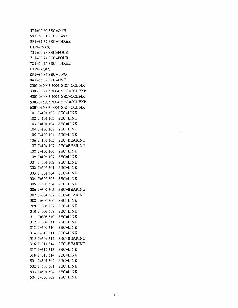
57 J=59,60 SEC=ONE
58 J=60,61 SEC=TWO
59 J=61,62 SEC=THREE
GEN=59,69,1
70 J=72,73 SEC=FOUR
71 J=73,74 SEC=FOUR
72 J=74,75 SEC=THREE
GEN=72,82, 1
83 J=85,86 SEC=TWO
84 J=86,87 SEC=ONE
2003 J=2003,2004 SEC=COLFIX
3003 J=3003,3004 SEC=COLEXP
4003 J=4003,4004 SEC=COLFIX
5003 J=5003,5004 SEC=COLEXP
6003 J=6003,6004 SEC=COLFIX
101 J=101,102 SEC=LINK
102 J=101,103 SEC=LINK
103 J=101,104 SEC=LINK
104 J=102,103 SEC=LINK
105 J=103,104 SEC=LINK
106 J=102,105 SEC=BEARING
107 J=104,107 SEC=BEARING
108 J=105,106 SEC=LINK
109 J=106,107 SEC=LINK
301 J=301,302 SEC=LINK
302 J=303,301 SEC=LINK
303 J=301,304 SEC=LINK
304 J=302,303 SEC=LINK
305 J=303,304 SEC=LINK
306 J=302,305 SEC=BEARING
307 J=304,307 SEC=BEARING
308 J=305,306 SEC=LINK
309 J=306,307 SEC=LINK
310 J=308,309 SEC=LINK
311 J=308,310 SEC=LINK
312 J=308,311 SEC=LINK
313 J=309,310 SEC=LINK
314 J=310,311 SEC=LINK
315 J=309,312 SEC=BEARING
316 J=311,314 SEC=BEARING
317 J=312,313 SEC=LINK
318 J=313,314 SEC=LINK
501 J=501,502 SEC=LINK
502 J=503,501 SEC=LINK
503 J=501,504 SEC=LINK
504 J=502,503 SEC=LINK
137

505 J=503,504
506 J=502,505
507 J=504,507508 J=505,506
509 J=506,507
510 J=508,509
511 J=508,510
512 J=508,511
513 J=509,510
514 J=510,511
515 J=509,512
516 J=511,514
517 J=512,513
518 J=513,514
701 J=701,702
702 J=703,701
703 J=701,704
704 J=702,703
705 J=703,704706 J=702,705
707 J=704,707
708 J=705,706
709 J=706,707
SEC=LINKSEC=BEARING
SEC=BEARING
SEC=LINKSEC=LINK
SEC=LINK
SEC=LINK
SEC=LINK
SEC=LINK
SEC=LINK
SEC=BEARING
SEC=BEARINGSEC=LINKSEC=LINK
SEC=LINKSEC=LINK
SEC=LINK
SEC=LINK
SEC=LINK
SEC=BEARINGSEC=BEARING
SEC=LINK
SEC=LINK
LOADNAME=DEAD
TYPE=GRAV ELEM=FRAME
ADD=* UZ=-
TYPE=FORC
ADD=3004,5004,2000 UZ=-421.440ADD= 101,701,600 UZ=-421.440TYPE=DIST
ADD=1,84, 1TYPE=FORCADD= 1,15,14ADD=30,44,14
ADD=59,73,14
ADD=15,29,14
ADD=44,58,14
ADD=73,87,14
UZ=130
UY=18087 UZ=-1846
UY=18087 UZ=-1846
UY=18087 UZ=-1846
UY=-18087 UZ=-1846
UY=-18087 UZ--1846
UY=-18087 UZ=-1846
MODESTYPE=EIGEN N=50
FUNCTION
NAME=ACCSPEC NPL=1
138
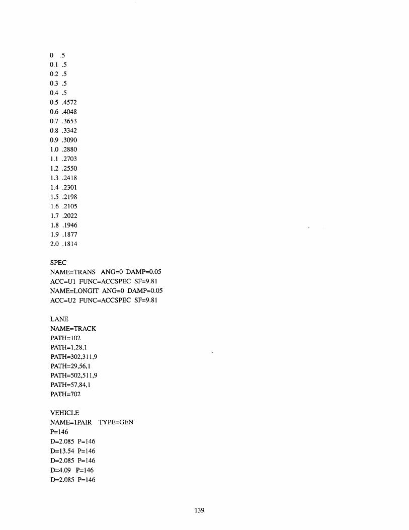
0 .50.1 .50.2 .50.3 .50.4 .50.5 .45720.6 .4048
0.7 .36530.8 .3342
0.9 .3090
1.0 .2880
1.1 .2703
1.2 .25501.3 .2418
1.4 .2301
1.5 .2198
1.6 .2105
1.7 .2022
1.8 .19461.9 .1877
2.0 .1814
SPECNAME=TRANS ANG=0 DAMP=0.05
ACC=U1 FUNC=ACCSPEC SF=9.81
NAME=LONGIT ANG=0 DAMP=0.05
ACC=U2 FUNC=ACCSPEC SF=9.81
LANE
NAME=TRACK
PATH= 102
PATH=1,28,1PATH=302,311,9
PATH=29,56,1PATH=502,511,9
PATH=57,84,1PATH=702
VEHICLE
NAME=1PAIR TYPE=GEN
P=146
D=2.085 P=146
D=13.54 P=146
D=2.085 P=146
D=4.09 P=146
D=2.085 P=146
139

D=13.54 P=146D=2.085 P=146
NAME=2PAIR TYPE=GENP=146D=2.085 P=146
D=13.54 P=146
D=2.085 P=146D=4.09 P=146D=2.085 P=146
D=13.54 P=146
D=2.085 P=146
D=4.09 P=146
D=2.085 P=146
D=13.54 P=146
D=2.085 P=146
D=4.09 P=146D=2.085 P=146D=13.54 P=146
D=2.085 P=146
NAME=3PAIR TYPE=GENP=146
D=2.085 P=146D=13.54 P=146
D=2.085 P=146D=4.09 P=146D=2.085 P=146
D=13.54 P=146D=2.085 P=146
D=4.09 P=146D=2.085 P=146D=13.54 P=146D=2.085 P=146
D=4.09 P=146D=2.085 P=146D=13.54 P=146
D=2.085 P=146
D=4.09 P=146
D=2.085 P=146
D=13.54 P=146
D=2.085 P=146
D=4.09 P=146
D=2.085 P=146
D=13.54 P=146
D=2.085 P=146
VEHICLE CLASS
140
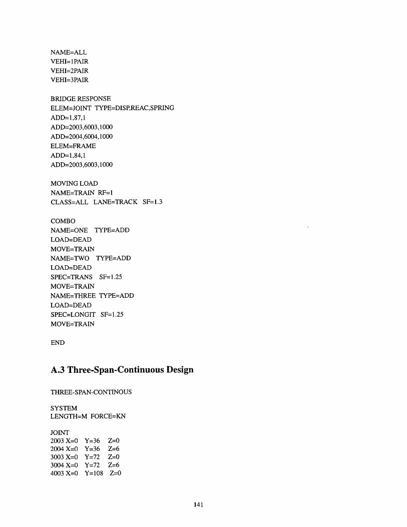
NAME=ALLVEHI=1 PAIR
VEHI=2PAIRVEHI=3PAIR
BRIDGE RESPONSE
ELEM=JOINT TYPE=DISP,REAC,SPRING
ADD=1,87,1
ADD=2003,6003,1000
ADD=2004,6004,1000ELEM=FRAME
ADD=1,84,1
ADD=2003,6003,1000
MOVING LOAD
NAME=TRAIN RF=1
CLASS=ALL LANE=TRACK SF=1.3
COMBO
NAME=ONE TYPE=ADD
LOAD=DEAD
MOVE=TRAINNAME=TWO TYPE=ADD
LOAD=DEAD
SPEC=TRANS SF= 1.25
MOVE=TRAIN
NAME=THREE TYPE=ADD
LOAD=DEAD
SPEC=LONGIT SF=1.25
MOVE=TRAIN
END
A.3 Three-Span-Continuous Design
THREE-SPAN-CONTINOUS
SYSTEMLENGTH=M FORCE=KN
JOINT2003 X=0 Y=36 Z=02004 X=0 Y=36 Z=63003 X=0 Y=72 Z=03004 X=0 Y=72 Z=64003 X=0 Y=108 Z=0
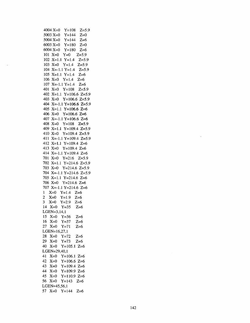
4004 X=0 Y=108 Z=5.95003 X=0 Y=144 Z=05004 X=0 Y=144 Z=66003 X=0 Y=180 Z=06004 X=0 Y=180 Z=-6101 X=0 Y=0 Z=5.9102 X=1.1 Y=1.4 Z=5.9103 X=0 Y=1.4 Z=-5.9104 X=-1.1 Y=1.4 Z=5.9105 X=I.1 Y=1.4 Z=6106 X=0 Y=1.4 Z=6107 X=-1.1 Y=1.4 Z=6401 X=0 Y=108 Z=5.9402 X=1.1 Y=106.6 Z=5.9403 X=0 Y=106.6 Z=5.9404 X=-1.1 Y=106.6 Z-5.9405 X=1.1 Y=106.6 Z=6406 X=0 Y=106.6 Z=6407 X=-1.1 Y=106.6 Z=6408 X=0 Y=108 Z=5.9409 X=1.1 Y=109.4 Z=5.9410 X=0 Y=109.4 Z=5.9411 X=-1.1 Y=109.4 Z=5.9412 X=I.1 Y=109.4 Z=6413 X=0 Y=109.4 Z=6414 X=-I.1 Y=109.4 Z=-6701 X=0 Y=216 Z=5.9702 X=1.1 Y=214.6 Z=5.9703 X=0 Y=214.6 Z=-5.9704 X=-1.1 Y=214.6 Z=5.9705 X=1.1 Y=214.6 Z=6706 X=0 Y=214.6 Z=6707 X=-1.1 Y=214.6 Z=61 X=0 Y= 1.4 Z=62 X=0 Y=1.9 Z=63 X=0 Y=2.9 Z=614 X=0 Y=35 Z=6LGEN=3, 14,115 X=0 Y=36 Z=616 X=0 Y=37 Z=627 X=0 Y=71 Z=6LGEN= 16,27,128 X=0 Y=72 Z=629 X=0 Y=73 Z=640 X=0 Y=105.1 Z=6LGEN=29,40,141 X=0 Y=106.1 Z=642 X=0 Y=106.6 Z=643 X=0 Y=109.4 Z=644 X=0 Y=109.9 Z=645 X=0 Y=110.9 Z=656 X=0 Y=143 Z=6LGEN=45,56, 157 X=0 Y=144 Z=6
142

58 X=0 Y=145 Z=669 X=0 Y=179 Z=6LGEN=58,69,170 X=0 Y=180 Z=671 X=0 Y=181 Z=682 X=O Y=213.1 Z=6LGEN=71,82,183 X=0 Y=214.1 Z=684 X=0 Y=214.6 Z=6
RESTRAINTADD=2003,6003,1000 DOF=ALLADD=101,701,600 DOF=ALL
WELDNAME=ALL TOL=0.000001ADD=*
MASSADD=4004 UX=42.96 UY=42.96 UZ=42.96ADD= 101,701,600 UX=42.96 UY=42.96 UZ=42.96
MATERIALNAME=BEAM TYPE=ISO M=2.4 W=23.544E=27670000 U=0.30 A=0.000011NAME=COLUMN TYPE=ISO M=2.4 W=23.544E=23420000 U=0.25NAME=TBEAM TYPE=ISOE=27670000 U=0.30NAME=ELASTO TYPE=ORTHOE=1284349,1284349,1284349 G=1400,1400,1400
FRAME SECTIONNAME=ONE TYPE=PRISM MAT=BEAM A=4.2374 J=1.054 I=.43567,7.1614AS=2.862,3.2669 MPL=3.99 WPL=39.127NAME=TWO TYPE=PRISM MAT=BEAM A=6.6136 J=3.883 1=2.8134,9.1271AS=2.900,3.480 MPL=3.99 WPL=39.127NAME=THREE TYPE=PRISM MAT=BEAM A=3.0664 J=2.976 1=1.8551,6.8861AS=1.175,1.460 MPL=3.99 WPL=39.127NAME=FOUR TYPE=PRISM MAT=BEAM A=6.9040 J=4.076 1=2.9480,9.1760AS=3.183,3.850 MPL=3.99 WPL=39.127NAME=COLFIX TYPE=PRISM MAT=COLUMN SH=P T=1.83NAME=COLEXP TYPE=PRISM MAT=COLUMN SH=P T=1.83NAME=LINK TYPE=PRISM MAT=TBEAM A=1000 J=1000 I=1000,1000AS= 1000, 1000NAME=BEARING TYPE=PRISM MAT=ELASTO SH=R T=0.85,0.85
FRAME1 J=1,2 SEC=ONE2 J=2,3 SEC=TWO3 J=3,4 SEC=THREEGEN=3,13,114 J=14,15 SEC=FOUR15 J=15,16 SEC=FOUR
143

16 J=16,17 SEC=THREEGEN=16,26,127 J=27,28 SEC=FOUR28 J=28,29 SEC=FOUR29 J=29,30 SEC=THREEGEN=29,39, 140 J=40,41 SEC=TWO41 J=41,42 SEC=ONE42 J=43,44 SEC=ONE43 J=44,45 SEC=TWO44 J=45,46 SEC=THREEGEN=44,54, 155 J=56,57 SEC=FOUR56 J=57,58 SEC=FOUR57 J=58,59 SEC=THREEGEN=57,67, 168 J=69,70 SEC=FOUR69 J=70,71 SEC=FOUR70 J=71,72 SEC=THREEGEN=70,80, 181 J=82,83 SEC=TWO82 J=83,84 SEC=ONE2003 J=2003,2004 SEC=COLFIX3003 J=3003,3004 SEC=COLFIX4003 J=4003,4004 SEC=COLEXP5003 J=5003,5004 SEC=COLFIX6003 J=6003,6004 SEC=COLFIX101 J=101,102 SEC=LINK102 J=101,103 SEC=LINK103 J=101,104 SEC=LINK104 J=102,103 SEC=LINK105 J=103,104 SEC=LINK106 J=102,105 SEC=BEARING107 J=104,107 SEC=BEARING108 J=105,106 SEC=LINK109 J=106,107 SEC=LINK401 J=401,402 SEC=LINK402 J=403,401 SEC=LINK403 J=401,404 SEC=LINK404 J=402,403 SEC=LINK405 J=403,404 SEC=LINK406 J=402,405 SEC=BEARING407 J=404,407 SEC=BEARING408 J=405,406 SEC=LINK409 J=406,407 SEC=LINK410 J=408,409 SEC=LINK411 J=408,410 SEC=LINK412 J=408,411 SEC=LINK413 J=409,410 SEC=LINK414 J=410,411 SEC=LINK415 J=409,412 SEC=BEARING416 J=411,414 SEC=BEARING417 J=412,413 SEC=LINK418 J=413,414 SEC=LINK
144
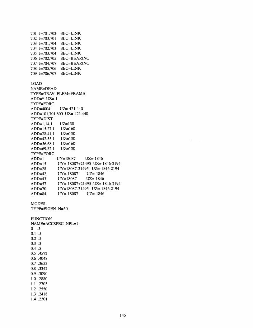
701 J=701,702702 J=703,701703 J=701,704704 J=702,703705 J=703,704706 J=702,705707 J=704,707708 J=705,706709 J=706,707
SEC=LINKSEC=LINKSEC=LINKSEC=LINKSEC=LINKSEC=BEARINGSEC=BEARINGSEC=LINKSEC=LINK
LOADNAME=DEADTYPE=GRAV ELEM=FRAMEADD=* UZ=-lTYPE=FORCADD=4004 UZ=-421.440ADD=101,701,600 UZ=-421.440TYPE=DISTADD= 1,14,1 UZ=130ADD=15,27,1 UZ=160ADD=28,41,1 UZ=130ADD=42,55,1 UZ=130ADD=56,68,1 UZ=160ADD=69,82,1 UZ=130TYPE=FORCADD=1 UY= 18087 UZ=- 1846ADD=15 UY=-18087+21495 UZ=-1846-2194ADD=28 UY=18087-21495 UZ=- 1846-2194ADD=42 UY=- 18087 UZ=- 1846ADD=43 UY= 18087 UZ=- 1846ADD=57 UY=-18087+21495 UZ=-1846-2194ADD=70 UY= 18087-21495 UZ=- 1846-2194ADD=84 UY=- 18087 UZ=-1846
MODESTYPE=EIGEN N=50
FUNCTIONNAME=ACCSPEC NPL=0 .50.1 .50.2 .50.3 .50.4 .50.5 .45720.6 .40480.7 .36530.8 .33420.9 .30901.0 .28801.1 .27031.2 .25501.3 .24181.4 .2301
145

1.5 .21981.6 .21051.7 .20221.8 .19461.9 .18772.0 .1814
SPECNAME=TRANS ANG=0 DAMP=0.05ACC=U1 FUNC=ACCSPEC SF=9.81NAME=LONGIT ANG=O DAMP=0.05ACC=U2 FUNC=ACCSPEC SF=9.81
LANENAME=TRACKPATH=102PATH=1,41,1PATH=402,411,9PATH=42,82,1PATH=702
VEHICLENAME=1PAIR TYPE=GENP=146D=2.085 P=146D=13.54 P=146D=2.085 P=146D=4.09 P= 146D=2.085 P=146D=13.54 P=146D=2.085 P=146NAME=2PAIR TYPE=GENP=146D=2.085 P=146D=13.54 P=146D=2.085 P=146D=4.09 P=146D=2.085 P=146D=13.54 P=146D=2.085 P=146D=4.09 P=146D=2.085 P=146D=13.54 P=146D=2.085 P=146D=4.09 P=146D=2.085 P=146D=13.54 P=146D=2.085 P=146NAME=3PAIR TYPE=GENP=146D=2.085 P=146D=13.54 P=146D=2.085 P=146D=4.09 P=146
146

D=2.085 P=146D=13.54 P=146D=2.085 P=146D=4.09 P=146D=2.085 P=146D=13.54 P=146D=2.085 P=146D=4.09 P=146D=2.085 P=146D=13.54 P=146D=2.085 P=146D=4.09 P=146D=2.085 P=146D=13.54 P=146D=2.085 P=146D=4.09 P=146D=2.085 P=146D=13.54 P=146D=2.085 P=146
VEHICLE CLASSNAME=ALLVEHI=IPAIRVEHI=2PAIRVEHI=3PAIR
BRIDGE RESPONSEELEM=JOINT TYPE=DISP,REAC,SPRINGADD=1,84,1ADD=2003,6003, 1000ADD=2004,6004, 1000ELEM=FRAMEADD=1,82,1ADD=2003,6003, 1000
MOVING LOADNAME=TRAIN RF= 1CLASS=ALL LANE=TRACK SF=1.3
COMBONAME=ONE TYPE=ADDLOAD=DEADMOVE=TRAINNAME=TWO TYPE=ADDLOAD=DEADSPEC=TRANS SF= 1.25MOVE=TRAINNAME=THREE TYPE=ADDLOAD=DEADSPEC=LONGIT SF=1.25MOVE=TRAIN
END
147
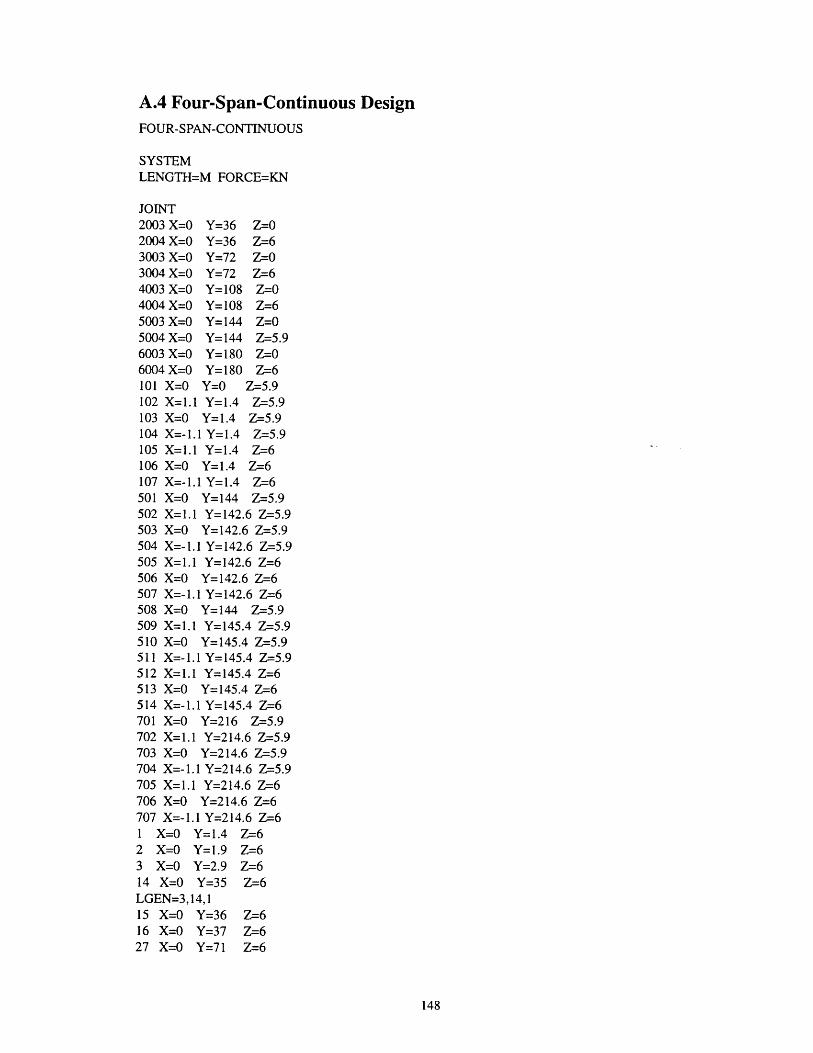
A.4 Four-Span-Continuous DesignFOUR-SPAN-CONTINUOUS
SYSTEMLENGTH=M FORCE=KN
JOINT2003 X=0 Y=36 Z=02004 X=0 Y=36 Z=63003 X=0 Y=72 Z=03004 X=0 Y=72 Z=64003 X=0 Y=108 Z=O4004 X=0 Y=108 Z=65003 X=0 Y=144 Z=O5004 X=0 Y=144 Z=5.96003 X=0 Y=180 Z=06004 X=0 Y=180 Z=6101 X=O Y=O Z-5.9102 X=1.1 Y=1.4 Z-=5.9103 X=0O Y=1.4 Z-5.9104 X=-1.1 Y=1.4 Z=5.9105 X=I.1 Y=1.4 Z=6106 X=0 Y= 1.4 Z=6107 X=-1.1 Y=1.4 Z=6501 X=0 Y=144 Z-5.9502 X=1.1 Y=142.6 Z-5.9503 X=0 Y=142.6 Z-=5.9504 X=-1.1 Y=142.6 Z-5.9505 X=1.1 Y=142.6 Z=6506 X=0 Y=142.6 Z=6507 X=-1.1 Y=142.6 Z=6508 X=0 Y=144 Z-=5.9509 X=1.1 Y=145.4 Z-=5.9510 X=0 Y=145.4 Z-=5.9511 X=-1.1 Y=145.4 Z-5.9512 X=1.1 Y=145.4 Z=6513 X=0 Y=145.4 Z=6514 X=-1.1 Y=145.4 Z-6701 X=0 Y=216 Z-=5.9702 X=1.1 Y=214.6 Z-=5.9703 X=0 Y=214.6 Z-=5.9704 X=-1.1 Y=214.6 Z-=5.9705 X=1.1 Y=214.6 Z-=6706 X=0 Y=214.6 Z=6707 X=-1.1 Y=214.6 Z=61 X=0 Y=1.4 Z=62 X=0 Y=1.9 Z=63 X=0 Y=2.9 Z=614 X=0 Y=35 Z=6LGEN=3,14,115 X=0 Y=36 Z=616 X=0 Y=37 Z=627 X=0 Y=71 Z=6
148

LGEN=16,27,128 X=0 Y=72 Z=629 X=0 Y=73 Z=640 X=O Y=107 Z=6LGEN=29,40,141 X=O Y=108 Z=642 X=O Y=109 Z=653 X=O Y=141.1 Z=6LGEN=42,53,154 X=O Y=142.1 Z=655 X=0 Y=142.6 Z=656 X=0 Y=145.4 Z=657 X=0 Y=145.9 Z=658 X=0 Y=146.9 Z=669 X=O Y=179 Z=6LGEN=58,69,170 X=0 Y=180 Z=671 X=O Y=181 Z=682 X=0 Y=213.1 Z=6LGEN=71,82,183 X=O Y=214.1 Z=684 X=O Y=214.6 Z=6
RESTRAINTADD=2003,6003,1000 DOF=ALLADD=101,701,600 DOF=ALL
WELDNAME=ALL TOL=0.000001ADD=*
MASSADD=101,701,600 UX=42.96 UY=42.96 UZ=42.96ADD=5004 UX=42.96 UY=42.96 UZ=42.96
MATERIALNAME=BEAM TYPE=ISO M=2.4 W=23.544E=34970000 U=0.30 A=0.000011NAME=COLUMN TYPE=ISO M=2.4 W=23.544E=27670000 U=0.25NAME=TBEAM TYPE=ISOE=34970000 U=0.30NAME=ELASTO TYPE=ORTHOE=1496953,1496953,1496953 G=1400,1400,1400NAME=ELASTO2 TYPE=ORTHOE=898736,898736,898736 G= 1400,1400,1400
FRAME SECTIONNAME=ONE TYPE=PRISM MAT=BEAM A=4.2374 J=1.054 I=.43567,7.1614AS=2.862,3.2669 MPL=3.99 WPL=39.127NAME=TWO TYPE=PRISM MAT=BEAM A=6.6136 J=3.883 1=2.8134,9.1271AS=2.900,3.480 MPL=3.99 WPL=39.127NAME=THREE TYPE=PRISM MAT=BEAM A=3.0664 J=2.976 I=1.8551,6.8861AS=1.175,1.460 MPL=3.99 WPL=39.127
149
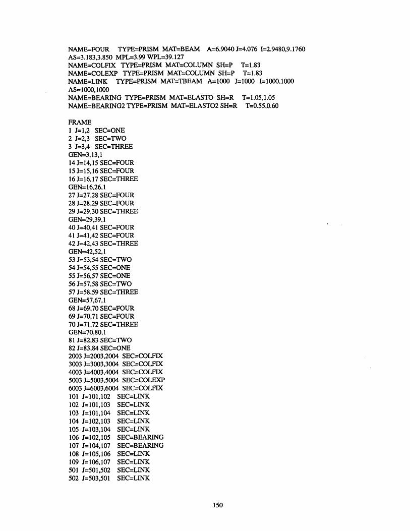
NAME=FOUR TYPE=PRISM MAT=BEAM A=6.9040 J=4.076 I=2.9480,9.1760AS=3.183,3.850 MPL=3.99 WPL=39.127NAME=-COLFIX TYPE=PRISM MAT=COLUMN SH=P T=1.83NAME=COLEXP TYPE=PRISM MAT=COLUMN SH=P T=1.83NAME=LINK TYPE=PRISM MAT=TBEAM A=1000 J=1000 I=1000,1000AS=1000,1000NAME=BEARING TYPE=PRISM MAT=ELASTO SH=R T=1.05,1.05NAME=BEARING2 TYPE=PRISM MAT=ELASTO2 SH=R T=0.55,0.60
FRAME1 J=1,2 SEC=ONE2 J=2,3 SEC=TWO3 J=3,4 SEC=THREEGEN=3,13,114 J=14,15 SEC=FOUR15 J=15,16 SEC=FOUR16 J=16,17 SEC=THREEGEN=16,26,127 J=27,28 SEC=FOUR28 J=28,29 SEC=FOUR29 J=29,30 SEC=THREEGEN=29,39,140 J=40,41 SEC=FOUR41 J=41,42 SEC=FOUR42 J=42,43 SEC=THREEGEN=42,52,153 J=53,54 SEC=TWO54 J=54,55 SEC=ONE55 J=56,57 SEC=ONE56 J=57,58 SEC=TWO57 J=58,59 SEC=THREEGEN=57,67, 168 J=69,70 SEC=FOUR69 J=70,71 SEC=FOUR70 J=71,72 SEC=THREEGEN=70,80,181 J=82,83 SEC=TWO82 J=83,84 SEC=ONE2003 J=2003,2004 SEC=COLFIX3003 J=3003,3004 SEC=COLFIX4003 J=4003,4004 SEC=COLFIX5003 J=5003,5004 SEC=COLEXP6003 J=6003,6004 SEC=COLFIX101 J=101,102 SEC=LINK102 J=101,103 SEC=LINK103 J=101,104 SEC=LINK104 J=102,103 SEC=LINK105 J=103,104 SEC=LINK106 J=102,105 SEC=BEARING107 J=104,107 SEC=BEARING108 J=105,106 SEC=LINK109 J=106,107 SEC=LINK501 J=501,502 SEC=LINK502 J=503,501 SEC=LINK
150
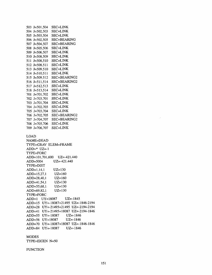
503 J=501,504 SEC=LINK504 J=502,503 SEC=LINK505 J=503,504 SEC=LINK506 J=502,505 SEC=BEARING507 J=504,507 SEC=BEARING508 J=505,506 SEC=LINK509 J=506,507 SEC=LINK510 J=508,509 SEC=LINK511 J=508,510 SEC=LINK512 J=508,511 SEC=LINK513 J=509,510 SEC=LINK514 J=510,511 SEC=LINK515 J=509,512 SEC=BEARING2516 J=511,514 SEC=BEARING2517 J=512,513 SEC=LINK518 J=513,514 SEC=LINK701 J=701,702 SEC=LINK702 J=703,701 SEC=LINK703 J=701,704 SEC=LINK704 J=702,703 SEC=LINK705 J=703,704 SEC=LINK706 J=702,705 SEC=BEARING2707 J=704,707 SEC=BEARING2708 J=705,706 SEC=LINK709 J=706,707 SEC=LINK
LOADNAME=DEADTYPE=GRAV ELEM=FRAMEADD=* UZ=-TYPE=FORCADD=101,701,600 UZ=-421.440ADD=5004 UZ=-421.440TYPE=DISTADD=1,14,1 UZ=130ADD= 15,27,1 UZ=160ADD=28,40,1 UZ=160ADD=41,54,1 UZ-130ADD=55,68,1 UZ=130ADD=69,82,1 UZ- 130TYPE=FORCADD=1 UY=18087 UZ=-1845ADD=15 UY=-18087+21495 UZ=-1846-2194ADD=28 UY=-21495+21495 UZ=-2194-2194ADD=41 UY=-21495+18087 UZ=-2194-1846ADD=55 UY=- 18087 UZ-- 1846ADD=56 UY=18087 UZ=-1846ADD=70 UY=-18087+18087 UZ=-1846-1846ADD=84 UY=-18087 UZ=- 1846
MODESTYPE=EIGEN N=50
FUNCTION
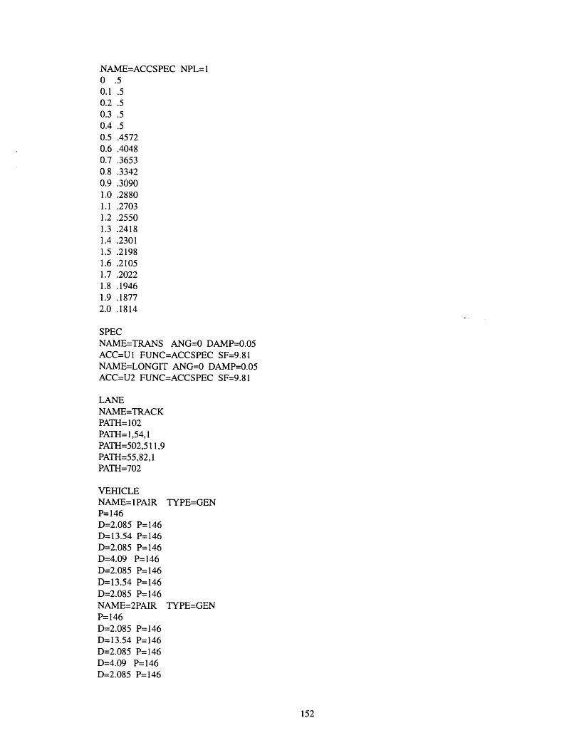
NAME=ACCSPEC NPL=10 .50.1 .50.2 .50.3 .50.4 .50.5 .45720.6 .40480.7 .36530.8 .33420.9 .30901.0 .28801.1 .27031.2 .25501.3 .24181.4 .23011.5 .21981.6 .21051.7 .20221.8 .19461.9 .18772.0 .1814
SPECNAME=TRANS ANG=0 DAMP=0.05ACC=U1 FUNC=ACCSPEC SF=9.81NAME=LONGIT ANG=0 DAMP=0.05ACC=U2 FUNC=ACCSPEC SF=9.81
LANENAME=TRACKPATH= 102PATH=1,54,1PATH=502,511,9PATH=55,82,1PATH=702
VEHICLENAME=1PAIR TYPE=GENP= 146D=2.085 P=146D=13.54 P=146D=2.085 P=146D=4.09 P=146D=2.085 P=146D=13.54 P=146D=2.085 P=146NAME=2PAIR TYPE=GENP=146D=2.085 P=146D=13.54 P=146D=2.085 P=146D=4.09 P=146D=2.085 P=146
152
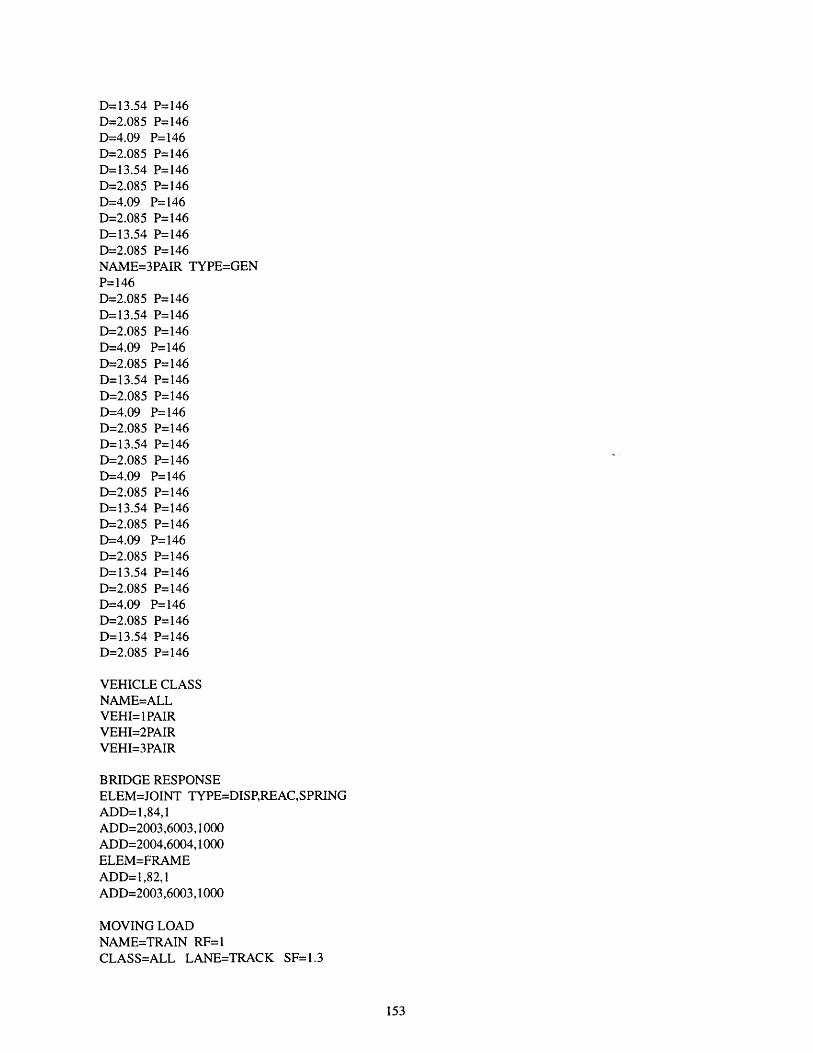
D=13.54 P=146D=2.085 P=146D=4.09 P=146D=2.085 P=146D=13.54 P=146D=2.085 P=146D=4.09 P=146D=2.085 P=146D=13.54 P=146D=2.085 P=146NAME=3PAIR TYPE=GENP=146D=2.085 P=146D=13.54 P=146D=2.085 P=146D=4.09 P=146D=2.085 P=146D=13.54 P=146D=2.085 P=146D=4.09 P=146D=2.085 P=146D=13.54 P=146D=2.085 P=146D=4.09 P=146D=2.085 P=146D= 13.54 P=146D=2.085 P=146D=4.09 P=146D=2.085 P=146D=13.54 P=146D=2.085 P=146D=4.09 P=146D=2.085 P=146D=13.54 P=146D=2.085 P=146
VEHICLE CLASSNAME=ALLVEHI=1PAIRVEHI=2PAIRVEHI=3PAIR
BRIDGE RESPONSEELEM=JOINT TYPE=DISP,REAC,SPRINGADD= 1,84,1ADD=2003,6003, 1000ADD=2004,6004, 1000ELEM=FRAMEADD=1,82,1ADD=2003,6003,1000
MOVING LOADNAME=TRAIN RF=1CLASS=ALL LANE=TRACK SF=1.3
153
COMBONAME=ONE TYPE=ADDLOAD=DEADMOVE=TRAINNAME=TWO TYPE=ADDLOAD=DEADSPEC=TRANS SF= 1.25MOVE=TRAINNAME=THREE TYPE=ADDLOAD=DEADSPEC=LONGIT SF=1.25MOVE=TRAIN
END
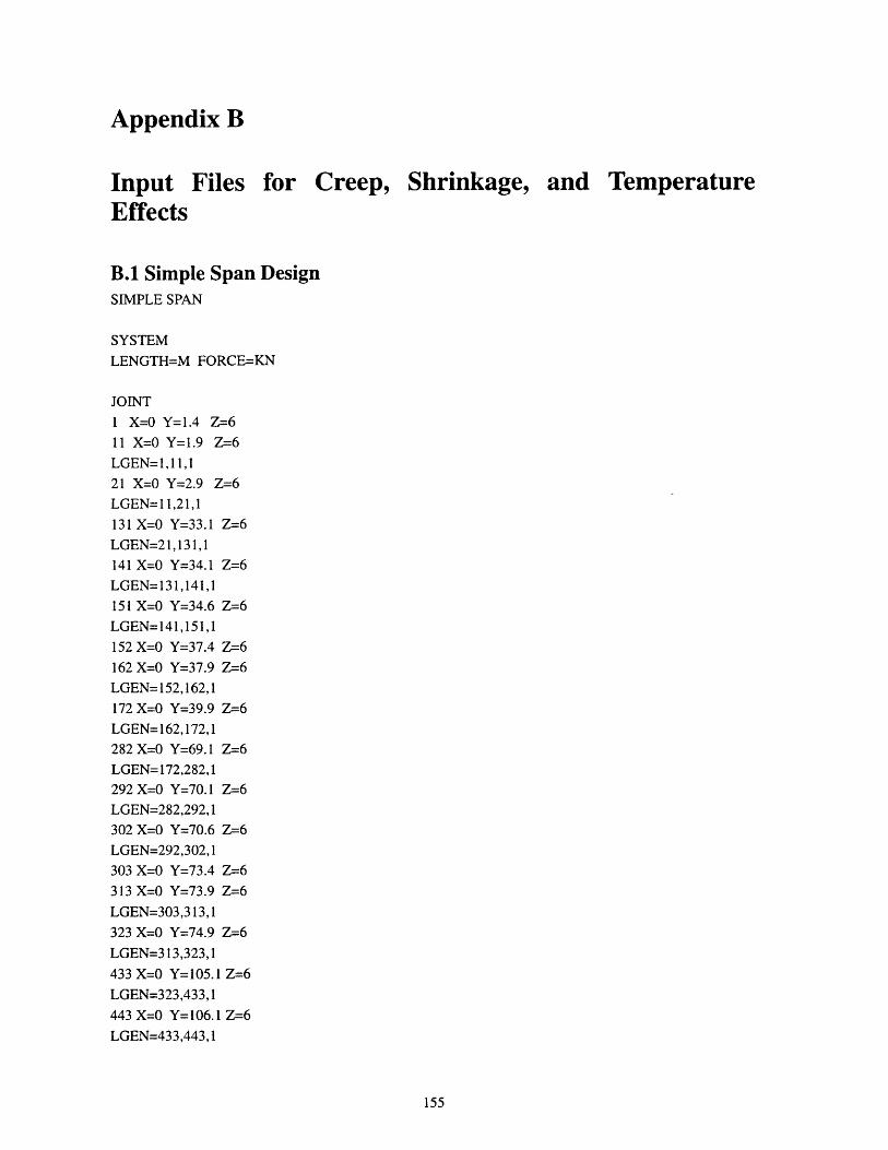
Appendix B
Input Files for Creep, Shrinkage, and TemperatureEffects
B.1 Simple Span DesignSIMPLE SPAN
SYSTEM
LENGTH=M FORCE=KN
JOINT
1 X=0 Y=1.4 Z=6
11 X=0 Y=1.9 Z=6
LGEN= 1,11,121 X=0 Y=2.9 Z=6
LGEN= 11,21,1131 X=0 Y=33.1 Z=6
LGEN=21,131,1141 X=0 Y=34.1 Z=6
LGEN=131,141,1151 X=0 Y=34.6 Z=6
LGEN=141,151,1152 X=0 Y=37.4 Z=6
162 X=0 Y=37.9 Z=6
LGEN= 152,162,1172 X=0 Y=39.9 Z=6
LGEN=162,172,1282 X=0 Y=69.1 Z=6
LGEN= 172,282,1292 X=0 Y=70.1 Z=6
LGEN=282,292,1302 X=0 Y=70.6 Z=6
LGEN=292,302,1303 X=0 Y=73.4 Z=6
313 X=0 Y=73.9 Z=6
LGEN=303,313,1323 X=0 Y=74.9 Z=6
LGEN=313,323,1433 X=0 Y=105.1 Z=6
LGEN=323,433,1443 X=0 Y=106.1 Z=6
LGEN=433,443,1
155

453 X=O Y=106.6 Z=6LGEN=443,453,1
454 X=0 Y=109.4 Z=6464 X=0 Y= 109.9 Z=6LGEN=454,464, 1474 X=0 Y=110.9 Z-6
LGEN=464,474,1584 X=0 Y=141.1 Z=6LGEN=474,584,1
594 X=O Y= 142.1 Z=6LGEN=584,594,1
604 X=0 Y=142.6 Z-6LGEN=594,604, 1605 X=0 Y= 145.4 Z=6615 X=0O Y=145.9 Z=6LGEN=605,615,1625 X=O Y=146.9 Z=6
LGEN=615,625,1735 X=0 Y= 177.1 Z=6LGEN=625,735,1745 X=O Y=178.1 Z=6LGEN=735,745,1755 X=0 Y=178.6 Z=6
LGEN=745,755,1756 X=O Y=181.4 Z=6766 X=O Y=181.9 Z=6LGEN=756,766,1776 X=0 Y= 182.9 Z=6LGEN=766,776,1886 X=0 Y=213.1 Z=6LGEN=776,886,1896 X=0 Y=214.1 Z=6LGEN=886,896,1906 X=0 Y=214.6 Z=6LGEN=896,906,1
2001 X=0 Y=1.4 Z=6.42011 X=0 Y= 1.9 Z=6.4
LGEN=2001,2011,12021 X=0 Y=2.9 Z=6.4
LGEN=2011,2021,12131 X=0 Y=33.1 Z=6.4
LGEN=2021,2131,12141 X=0 Y=34.1 Z=6.4LGEN=2131,2141,1
2151 X=0 Y=34.6 Z=6.4
156

LGEN=2141,2151,12152 X=0 Y=37.4 Z=6.4
2162 X=0 Y=37.9 Z=6.4
LGEN=2152,2162,12172 X=0 Y=39.9 Z=6.4
LGEN=2162,2172,12282 X=0 Y=69.1 Z=6.4
LGEN=2172,2282,12292 X=0 Y=70.1 Z=-6.4
LGEN=2282,2292,12302 X=0 Y=70.6 Z=6.4
LGEN=2292,2302,12303 X=0 Y=73.4 Z=6.4
2313 X=0 Y=73.9 Z=6.4
LGEN=2303,2313,12323 X=0 Y=74.9 Z=6.4
LGEN=2313,2323,12433 X=0 Y=105.1 Z=6.4
LGEN=2323,2433,12443 X=0 Y=106.1 Z=6.4
LGEN=2433,2443,12453 X=0 Y=106.6 Z=-6.4
LGEN=2443,2453,12454 X=0 Y=109.4 Z=6.42464 X=0 Y=109.9 Z=6.4
LGEN=2454,2464,12474 X=0 Y=110.9 Z=-6.4
LGEN=2464,2474,12584 X=0 Y=141.1 Z=6.4
LGEN=2474,2584,12594 X=0 Y=142.1 Z-6.4
LGEN=2584,2594,12604 X=0 Y=142.6 Z=6.4
LGEN=2594,2604,12605 X=0 Y=145.4 Z=6.4
2615 X=0 Y=145.9 Z=6.4
LGEN=2605,2615,12625 X=0 Y=146.9 Z=6.4
LGEN=2615,2625,1
2735 X=0 Y= 177.1 Z=6.4
LGEN=2625,2735,12745 X=0 Y=178.1 Z=6.4
LGEN=2735,2745,12755 X=0 Y=178.6 Z=6.4
LGEN=2745,2755,12756 X=0 Y= 181.4 Z=6.4
157
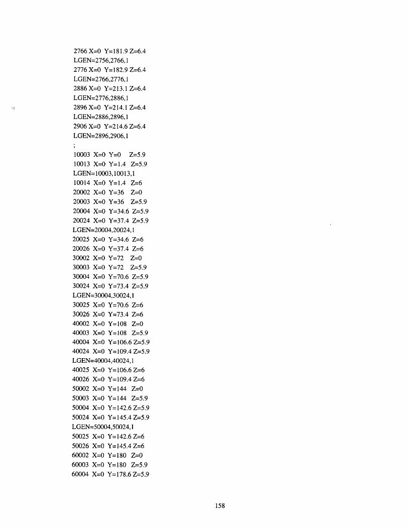
2766 X=0 Y=181.9 Z=6.4LGEN=2756,2766,12776 X=0 Y= 182.9 Z=6.4LGEN=2766,2776,12886 X=0 Y=213.1 Z=6.4
LGEN=2776,2886,1
2896 X=0 Y=214.1 Z=6.4
LGEN=2886,2896,1
2906 X=0 Y=214.6 Z=-6.4
LGEN=2896,2906,1
10003 X=O Y=0 Z=5.910013 X=0 Y=1.4 Z=5.9LGEN= 10003,10013,110014 X=0 Y=1.4 Z=620002 X=O Y=36 Z=0
20003 X=0 Y=36 Z=5.9
20004 X=0 Y=34.6 Z=5.920024 X=0 Y=37.4 Z=5.9
LGEN=20004,20024,1
20025 X=0 Y=34.6 Z=620026 X=0 Y=37.4 Z=630002 X=0 Y=72 Z=030003 X=0 Y=72 Z=5.930004 X=0 Y=70.6 Z=-5.930024 X=0 Y=73.4 Z=-5.9LGEN=30004,30024,1
30025 X=0 Y=70.6 Z=630026 X=0 Y=73.4 Z=640002 X=0 Y=108 Z=040003 X=0 Y=108 Z-=5.940004 X=0 Y=106.6 Z-=5.940024 X=0 Y=109.4 Z-=5.9LGEN=40004,40024, 140025 X=0 Y=106.6 Z-640026 X=0 Y=109.4 Z=6
50002 X=0 Y=144 Z=050003 X=0 Y=144 Z=5.9
50004 X=0 Y=142.6 Z=5.9
50024 X=0 Y= 145.4 Z-=5.9
LGEN=50004,50024,1
50025 X=0 Y=142.6 Z=6
50026 X=0 Y=145.4 Z=660002 X=0 Y= 180 Z=060003 X=0 Y=180 Z-=5.960004 X=0 Y=178.6 Z=5.9
158

60024 X=0 Y=181.4 Z=5.9
LGEN=60004,60024,160025 X=0 Y=178.6 Z=6
60026 X=0 Y=181.4 Z=6
70003 X=0 Y=216 Z=5.9
70013 X=O Y=214.6 Z=5.9
LGEN=70003,70013,170014 X=0 Y=214.6 Z=6
12003 X=0 Y=0 Z=6.4
12013 X=0 Y=1.4 Z=6.4
LGEN=12003,12013,122004 X=0 Y=34.6 Z=6.4
22024 X=0 Y=37.4 Z=6.4
LGEN=22004,22024,132004 X=0 Y=70.6 Z=6.4
32024 X=0 Y=73.4 Z=6.4
LGEN=32004,32024,142004 X=0 Y=106.6 Z=6.4
42024 X=0 Y=109.4 Z=6.4
LGEN=42004,42024,152004 X=0 Y=142.6 Z=6.4
52024 X=0 Y=145.4 Z-=6.4
LGEN=52004,52024,162004 X=0 Y=178.6 Z=6.4
62024 X=0 Y=181.4 Z=6.4
LGEN=62004,62024,172003 X=0 Y=216 Z-=6.4
72013 X=0 Y=214.6 Z=6.4
LGEN=72003,72013,1
RESTRAINT
ADD=20002,60002,10000 DOF=ALL
ADD= 12003,72003,60000 DOF=ALL
ADD= 10003,70003,60000 DOF=ALL
WELDNAME=ALL TOL=0.000001
ADD=*
MATERIAL
NAME=BEAM TYPE=ISO M=2.4 W=23.544
E=27670000 U=0.30 A=0.000011
NAME=COLUMN TYPE=ISO M=2.4 W=23.544
E=23420000 U=0.25
NAME=TBEAM TYPE=ISO
159

E=27670000 U=0.30 A=0.000011
NAME=ELASTO TYPE=ORTHO
E=1619956,1619956,1619956 G=1400,1400,1400
NAME=RAIL TYPE-ISO
E=2.1E8 U=0.30 A=12E-6
NAME=RSPRING TYPE=ISOE=8000
FRAME SECTION
NAME=ONE TYPE=PRISM MAT=BEAM A=4.2374 J=1.054 1=.43567,7.1614AS=2.862,3.2669
NAME=TWO TYPE=PRISM MAT=BEAM A=6.6136 J=3.883 1=2.8134,9.1271AS=2.900,3.480NAME=THREE TYPE=PRISM MAT=BEAM A=3.0664 J=2.976 I=1.8551,6.8861AS=1.175,1.460NAME=FOUR TYPE=PRISM MAT=BEAM A=6.9040 J=4.076 1=2.9480,9.1760AS=3.183,3.850NAME=COLFIX TYPE=PRISM MAT=COLUMN SH=P T=2.135
NAME=COLEXP TYPE=PRISM MAT=COLUMN SH=P T=1.83
NAME=LINK TYPE=PRISM MAT=TBEAM A=1000 J=1000 I=1000,1000AS=1000,1000
NAME=BEARING TYPE=PRISM MAT=ELASTO SH=R T=2*1.200,1.200
NAME=S1 TYPE=PRISM MAT=RSPRING A=1000 I=0.5/10/187.5J=1000
NAME=S2 TYPE=PRISM MAT=RSPRING A=1000 1=1/10/187.5J=1000NAME=S3 TYPE=PRISM MAT=RSPRING A=1000 1=32.1/110/187.5J=1000NAME=S4 TYPE=PRISM MAT=RSPRING A=1000 I=1/10/187.5J=1000NAME=S5 TYPE=PRISM MAT=RSPRING A=1000 I=1.4/10/96J=1000NAME=RAIL TYPE=PRISM MAT=RAIL A=2*7257.34/1000/1000 I=2*27304781.52/1000/1000/1000/1000
FRAME
1 J=1,2 SEC=ONE
GEN=1,10,1
11 J=11,12 SEC=TWO
GEN= 11,20,1
21 J=21,22 SEC=THREE
GEN=21,130,1
131 J=131,132 SEC=TWO
GEN= 131,140,1
141 J=141,142 SEC=ONEGEN=141,150,1
151 J=152,153 SEC=ONE
GEN=151,160,1
160

161 J=162,163 SEC=TWO
GEN= 161,170,1
171 J=172,173 SEC=THREE
GEN=171,280,1281 J=282,283 SEC=TWOGEN=281,290,1
291 J=292,293 SEC=ONE
GEN=291,300,1
301 J=303,304 SEC=ONE
GEN=301,310,1
311 J=313,314 SEC=TWO
GEN=311,320,1
321 J=323,324 SEC=THREE
GEN=321,430,1
431 J=433,434 SEC=TWO
GEN=431,440,1
441 J=443,444 SEC=ONE
GEN=441,450,1
451 J=454,455 SEC=ONE
GEN=451,460,1
461 J=464,465 SEC=TWO
GEN=461,470,1471 J=474,475 SEC=THREE
GEN=471,580,1
581 J=584,585 SEC=TWO
GEN=581,590,1
591 J=594,595 SEC=ONE
GEN=591,600,1601 J=605,606 SEC=ONE
GEN=601,610,1611 J=615,616 SEC=TWO
GEN=611,620,1621 J=625,626 SEC=THREE
GEN=621,730,1731 J=735,736 SEC=TWO
GEN=731,740,1
741 J=745,746 SEC=ONE
GEN=741,750,1
751 J=756,757 SEC=ONE
GEN=751,760,1
761 J=766,767 SEC=TWO
GEN=761,770,1
771 J=776,777 SEC=THREE
GEN=771,880,1
881 J=886,887 SEC=TWO
GEN=881,890,1
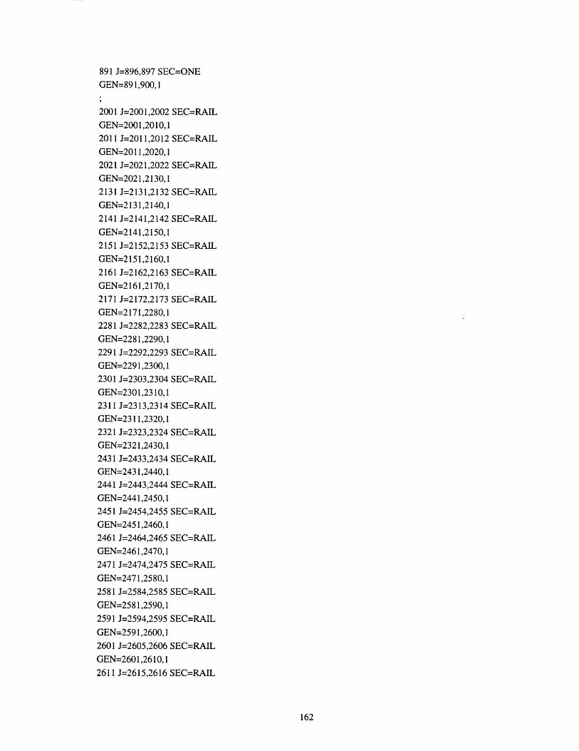
891 J=896,897 SEC=ONEGEN=89 1,900,1
2001 J=2001,2002 SEC=RAILGEN=2001,2010,1
2011 J=2011,2012 SEC=RAIL
GEN=2011,2020,1
2021 J=2021,2022 SEC=RAIL
GEN=2021,2130,1
2131 J=2131,2132 SEC=RAIL
GEN=2131,2140,1
2141 J=2141,2142 SEC=RAIL
GEN=2141,2150,1
2151 J=2152,2153 SEC=RAIL
GEN=2151,2160,1
2161 J=2162,2163 SEC=RAILGEN=2161,2170,1
2171 J=2172,2173 SEC=RAIL
GEN=2171,2280,12281 J=2282,2283 SEC=RAIL
GEN=2281,2290,1
2291 J=2292,2293 SEC=RAILGEN=2291,2300,1
2301 J=2303,2304 SEC=RAIL
GEN=2301,23 10,12311 J=2313,2314 SEC=RAILGEN=2311,2320,12321 J=2323,2324 SEC=RAILGEN=2321,2430,12431 J=2433,2434 SEC=RAILGEN=2431,2440,12441 J=2443,2444 SEC=RAILGEN=2441,2450,1
2451 J=2454,2455 SEC=RAILGEN=2451,2460,12461 J=2464,2465 SEC=RAIL
GEN=2461,2470,1
2471 J=2474,2475 SEC=RAIL
GEN=2471,2580,1
2581 J=2584,2585 SEC=RAIL
GEN=2581,2590,1
2591 J=2594,2595 SEC=RAIL
GEN=2591,2600,12601 J=2605,2606 SEC=RAIL
GEN=2601,2610,1
2611 J=2615,2616 SEC=RAIL
162

GEN=2611,2620,12621 J=2625,2626 SEC=RAIL
GEN=2621,2730,12731 J=2735,2736 SEC=RAIL
GEN=2731,2740,1
2741 J=2745,2746 SEC=RAIL
GEN=2741,2750,1
2751 J=2756,2757 SEC=RAIL
GEN=2751,2760,1
2761 J=2766,2767 SEC=RAIL
GEN=2761,2770,1
2771 J=2776,2777 SEC=RAIL
GEN=2771,2880,1
2881 J=2886,2887 SEC=RAIL
GEN=2881,2890,1
2891 J=2896,2897 SEC=RAIL
GEN=2891,2900,1
12003 J= 12003,12004 SEC=RAIL
GEN=12003,12012,1
22004 J=22004,22005 SEC=RAIL
GEN=22004,22023,132004 J=32004,32005 SEC=RAIL
GEN=32004,32023,142004 J=42004,42005 SEC=RAIL
GEN=42004,42023,1
52004 J=52004,52005 SEC=RAIL
GEN=52004,52023,162004 J=62004,62005 SEC=RAIL
GEN=62004,62023,1
72003 J=72003,72004 SEC=RAIL
GEN=72003,72012,1
10003 J=10003,10004
GEN= 10003,10012,110013 J=10013,10014
20002 J=20002,20003
20003 J=20004,20005
GEN=20003,20022,1
20023 J=20004,20025
20024 J=20024,20026
30002 J=30002,30003
30003 J=30004,30005
GEN=30003,30022, 1
30023 J=30004,30025
30024 J=30024,30026
SEC=LINK
SEC=BEARING
SEC=COLEXP
SEC=LINK
SEC=BEARING
SEC=BEARING
SEC=COLEXP
SEC=LINK
SEC=BEARING
SEC=BEARING
163

40002 J=40002,40003
40003 J=40004,40005GEN=40003,40022,140023 J=40004,40025
40024 J=40024,40026
50002 J=50002,50003
50003 J=50004,50005
GEN=50003,50022,1
50023 J=50004,50025
50024 J=50024,50026
60002 J=60002,6000360003 J=60004,60005
GEN=60003,60022, 160023 J=60004,6002560024 J=60024,60026
70003 J=70003,70004
GEN=70003,70012,1
70013 J=70013,70014
1001 J=1,2001GEN=1001,101 1,11012 J=12,2012
GEN=1012,1021,1
1022 J=22,2022
GEN= 1022,1131,11132 J=132,2132GEN= 1132,1141,1
1142 J=142,2142
GEN=1142,1151,1
1152 J=152,2152
GEN=1152,1162,11163 J=163,2163GEN=1163,1172,1
1173 J=173,2173
GEN= 1173,1302,11283 J=283,2283
GEN=1283,1292, 1
1293 J=293,2293
GEN= 1293,1302,1
1303 J=303,2303
GEN=1303,1313,1
1314 J=314,2314
GEN=1314,1323,1
1324 J=324,2324
GEN= 1324,1433,1
1434 J=434,2434
SEC=COLEXPSEC=LINK
SEC=BEARING
SEC=BEARING
SEC=COLEXP
SEC=LINK
SEC=BEARING
SEC=BEARING
SEC=COLEXP
SEC=LINK
SEC=BEARING
SEC=BEARING
SEC=LINK
SEC=BEARING
SEC=S1
SEC=S2
SEC=S3
SEC=S2
SEC=SI
SEC=S1
SEC=S2
SEC=S3
SEC=S2
SEC=S1
SEC=S1
SEC=S2
SEC=S3
SEC=S2
164

GEN= 1434,1443,1
1444 J=444,2444 SEC=S 1
GEN= 1444, 1453,1
1454 J=454,2454 SEC=S 1
GEN=1454,1464,11465 J=465,2465 SEC=S2
GEN= 1465,1474,1
1475 J=475,2475 SEC=S3
GEN=1475,1584,1
1585 J=585,2585 SEC=S2
GEN=1585, 1594,1
1595 J=595,2595 SEC=S 1
GEN= 1595,1604, 11605 J=605,2605 SEC=S 1
GEN=1605, 1615,1
1616 J=616,2616 SEC=S2
GEN=1616,1625,1
1626 J=626,2626 SEC=S3
GEN=1626,1735,1
1736 J=736,2736 SEC=S2
GEN=1736,1745,1
1746 J=746,2746 SEC=S 1
GEN= 1746,1755,1
1756 J=756,2756 SEC=S1
GEN= 1756,1766,11767 J=767,2767 SEC=S2
GEN= 1767,1776,1
1777 J=777,2777 SEC=S3
GEN= 1777,1886,1
1887 J=887,2887 SEC=S2
GEN=1887,1896,1
1897 J=897,2897 SEC=S1
GEN= 1897,1906,1
11004 J=10004,12004 SEC=S5
GEN=11004,11012,1
21005 J=20005,22005 SEC=S5
GEN=21005,21023,1
31005 J=30005,32005 SEC=S5
GEN=31005,31023,1
41005 J=40005,42005 SEC=S5
GEN=41005,41023,1
51005 J=50005,52005 SEC=S5
GEN=51005,51023,1
61005 J=60005,62005 SEC=S5
GEN=61005,61023,1
165

71004 J=70004,72004 SEC=S5
GEN=71004,71012,1
REFTEMP
ELEM=FRAME
ADD=1,900,1 T=299.15ADD=10003,10012,1 T=299.15
ADD=20003,20022,1 T=299.15
ADD=30003,30022,1 T=299.15
ADD=40003,40022,1 T=299.15ADD=50003,50022,1 T=299.15
ADD=60003,60022,1 T=299.15
ADD=70003,70012,1 T=299.15
ADD=2001,2900,1 T=300.15ADD=12003,12012,1 T=300.15
ADD=22003,22012,1 T=300.15
ADD=32004,32023,1 T=300.15
ADD=42003,42012,1 T=300.15
ADD=52004,52023,1 T=300.15
ADD=62003,62012,1 T=300.15
ADD=72003,72012,1 T=300.15
LOAD
NAME=CST
TYPE=TEMP ELEM=FRAMEADD=1,900,1 T=288.15-45 T2=10ADD=10003,10012,1 T=288.15-45 T2=10ADD=20003,20022,1 T=288.15-45 T2=10ADD=30003,30022,1 T=288.15-45 T2=10
ADD=40003,40022,1 T=288.15-45 T2=10ADD=50003,50022,1 T=288.15-45 T2=10ADD=60003,60022,1 T=288.15-45 T2=10ADD=70003,70012,1 T=288.15-45 T2=10ADD=2001,2900,1 T=283.15ADD=12003,12012,1 T=283.15ADD=22003,22012,1 T=283.15ADD=32004,32023,1 T=283.15
ADD=42003,42012,1 T=283.15
ADD=52004,52023,1 T=283.15
ADD=62003,62012,1 T=283.15
ADD=72003,72012,1 T=283.15
166

B.2 Two-Span-Continuous DesignTWO-SPAN-CONTINUOUS
SYSTEM
LENGTH=M FORCE=KN
JOINT
1 X=O Y=1.4 Z=611 X=O Y=1.9 Z=6
LGEN= 1,11,121 X=0 Y=2.9 Z=6
LGEN= 11,21,1131 X=0 Y=35 Z=6
LGEN=21,131,1141 X=0 Y=36 Z=6
LGEN=131,141,1151 X=0 Y=37 Z=6
LGEN=141,151,1261 X=0 Y=69.1 Z=6
LGEN=151,261,1271 X=0 Y=70.1 Z=6
LGEN=261,271,1281 X=0 Y=70.6 Z=6
LGEN=271,281,1282 X=O Y=73.4 Z=6
292 X=O Y=73.9 Z=-6
LGEN=282,292,1302 X=0 Y=74.9 Z=6
LGEN=292,302,1412 X=O Y= 107 Z=6
LGEN=302,412,1
422 X=0 Y=108 Z=6
LGEN=412,422,1432 X=O Y=109 Z=6
LGEN=422,432,1542 X=0 Y=141.1 Z=6
LGEN=432,542,1552 X=0 Y=142.1 Z=6
LGEN=542,552,1562 X=O Y=142.6 Z=6
LGEN=552,562,1
563 X=0 Y=145.4 Z=6
573 X=O Y=145.9 Z=6
LGEN=563,573,1
583 X=0 Y=146.9 Z=6
LGEN=573,583,1
167

693 X=O Y=179 Z=6LGEN=583,693,1
703 X=0 Y=180 Z=6
LGEN=693,703,1713 X=O Y=181 Z=6LGEN=703,713,1823 X=0 Y=213.1 Z=6LGEN=713,823,1
833 X=O Y=214.1 Z=6LGEN=823,833,1
843 X=0 Y=214.6 Z=6
LGEN=833,843,1
2001 X=0 Y=1.4 Z=6.42011 X=0 Y=1.9 Z=6.4LGEN=2001,2011,12021 X=0 Y=2.9 Z=6.4LGEN=2011,2021,12131 X=0 Y=35 Z=6.4
LGEN=2021,2131,1
2141 X=0 Y=36 Z=6.4
LGEN=2131,2141,12151 X=0 Y=37 Z=6.4LGEN=2141,2151,12261 X=0 Y=69.1 Z=6.4LGEN=2151,2261,12271 X=0 Y=70.1 Z=6.4LGEN=2261,2271,1
2281 X=0 Y=70.6 Z=6.4
LGEN=2271,2281,12282 X=0 Y=73.4 Z=6.42292 X=0 Y=73.9 Z-=6.4LGEN=2282,2292, 12302 X=0 Y=74.9 Z=6.4LGEN=2292,2302,12412 X=0 Y=107 Z-=6.4
LGEN=2302,2412,1
2422 X=0 Y=108 Z-=6.4LGEN=2412,2422,1
2432 X=0 Y=109 Z=6.4
LGEN=2422,2432, 12542 X=0 Y= 141.1 Z-=6.4
LGEN=2432,2542,1
2552 X=0 Y=142.1 Z=6.4LGEN=2542,2552,12562 X=0 Y= 142.6 Z=6.4
168

LGEN=2552,2562,1
2563 X=0 Y=145.4 Z=6.4
2573 X=0 Y=145.9 Z=6.4
LGEN=2563,2573,12583 X=0 Y=146.9 Z=6.4
LGEN=2573,2583,1
2693 X=O Y=179 Z=6.4
LGEN=2583,2693,12703 X=0 Y= 180 Z=6.4
LGEN=2693,2703,12713 X=0 Y= 181 Z=6.4
LGEN=2703,2713,12823 X=0 Y=213.1 Z=6.4
LGEN=2713,2823,12833 X=0 Y=214.1 Z=6.4
LGEN=2823,2833,12843 X=0 Y=214.6 Z=6.4
LGEN=2833,2843,1
10003 X=0 Y=O Z=5.9
10013 X=0 Y=1.4 Z=5.9
LGEN=10003,10013,110014 X=0 Y=1.4 Z=6
20002 X=0 Y=36 Z-0
20003 X=0 Y=36 Z=6
30002 X=0 Y=72 Z=0
30003 X=0 Y=72 Z=5.9
30004 X=0 Y=70.6 Z=5.9
30024 X=0 Y=73.4 Z=-5.9
LGEN=30004,30024,130025 X=0 Y=70.6 Z=6
30026 X=0 Y=73.4 Z=-6
40002 X=0 Y= 108 Z-040003 X=0 Y=108 Z=6
50002 X=0 Y=144 Z=0
50003 X=0 Y=144 Z=5.9
50004 X=0 Y=142.6 Z-5.9
50024 X=0 Y=145.4 Z=5.9
LGEN=50004,50024,1
50025 X=0 Y=142.6 Z=6
50026 X=0 Y=145.4 Z=-6
60002 X=0 Y= 180 Z=0
60003 X=0 Y=180 Z=670003 X=0 Y=216 Z=5.9
70013 X=0 Y=214.6 Z=5.9
LGEN=70003,70013,1
169
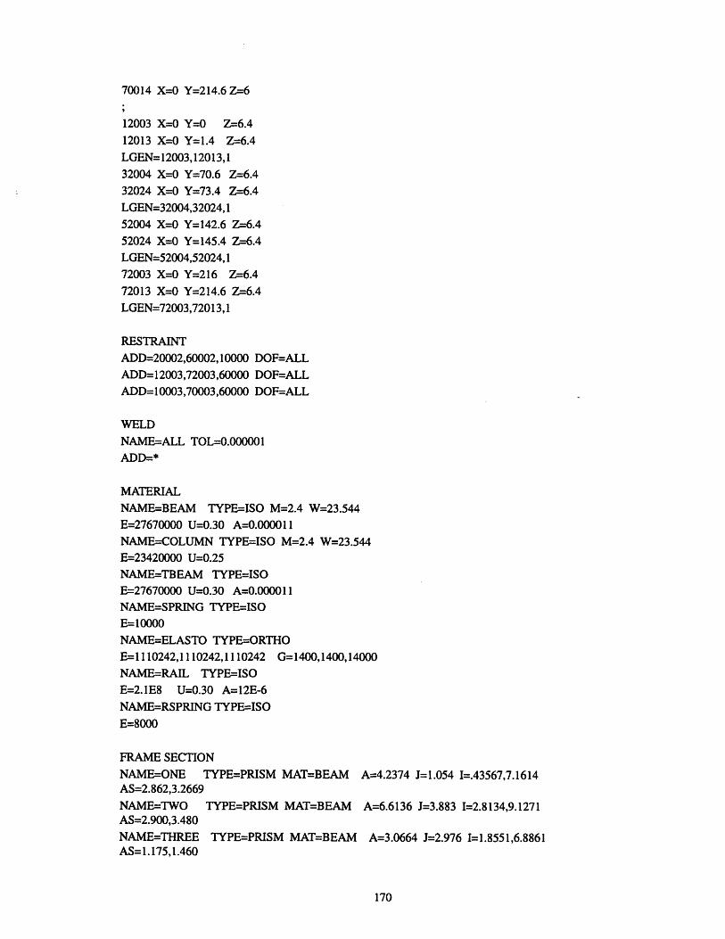
70014 X=0 Y=214.6 Z-6
12003 X=0 Y=0 Z=6.4
12013 X=0 Y=1.4 Z-=6.4LGEN= 12003,12013,132004 X=0 Y=70.6 Z=6.432024 X=0 Y=73.4 Z=-6.4
LGEN=32004,32024,152004 X=0 Y=142.6 Z=6.452024 X=0 Y=145.4 Z=6.4LGEN=52004,52024,172003 X=0 Y=216 Z-=6.472013 X=0 Y=214.6 Z-=6.4LGEN=72003,72013,1
RESTRAINTADD=20002,60002, 10000 DOF=ALLADD=1 2003,72003,60000 DOF=ALLADD= 10003,70003,60000 DOF=ALL
WELD
NAME=ALL TOL=0.000001ADD=*
MATERIAL
NAME=BEAM TYPE=ISO M=2.4 W=23.544E=27670000 U=0.30 A=0.000011
NAME=COLUMN TYPE-ISO M=2.4 W=23.544E=23420000 U=0.25NAME-TBEAM TYPE=ISOE=27670000 U=0.30 A=0.000011NAME=SPRING TYPE=ISOE=10000NAME=ELASTO TYPE=ORTHO
E=1110242,1110242,1110242 G= 1400,1400,14000
NAME=RAIL TYPE=ISOE=2.1E8 U=0.30 A=12E-6NAME=RSPRING TYPE=ISO
E=8000
FRAME SECTION
NAME=ONE TYPE=PRISM MAT=BEAM A=4.2374 J=1.054 I=.43567,7.1614AS=2.862,3.2669
NAME=TWO TYPE=PRISM MAT=BEAM A=6.6136 J=3.883 I=2.8134,9.1271AS=2.900,3.480
NAME=THREE TYPE=PRISM MAT=BEAM A=3.0664 J=2.976 I=1.8551,6.8861AS=1.175,1.460
170

NAME=FOUR TYPE=PRISM MAT=BEAM A=6.9040 J=4.076 1=2.9480,9.1760AS=3.183,3.850NAME=COLFIX TYPE=PRISM MAT=COLUMN SH=P T=2.135
NAME=COLEXP TYPE=PRISM MAT=COLUMN SH=P T=1.83
NAME=LINK TYPE=PRISM MAT=TBEAM A=1000 J=1000 I=1000,1000AS=1000,1000NAME=BEARING TYPE=PRISM MAT=ELASTO SH=R T=2*0.70,0.75
NAME=S1 TYPE=PRISM MAT=RSPRING A=1000 I=0.5/10/187.5J= 1000
NAME=S2 TYPE=PRISM MAT=RSPRING A=1000 1=1/10/187.5J= 1000
NAME=S3 TYPE=PRISM MAT=RSPRING A=1000 1=32.1/110/187.5J=1000NAME=S4 TYPE=PRISM MAT=RSPRING A=1000 1=1/10/187.5J= 1000NAME=S5 TYPE=PRISM MAT=RSPRING A=1000 1=1.4/10/96J= 1000NAME=RAIL TYPE=PRISM MAT=RAIL A=2*7257.34/1000/1000 I=2*27304781.52/1000/1000/1000/1000
FRAME
1 J=1,2 SEC=ONE
GEN= 1, 10, 111 J=11,12 SEC=TWO
GEN= 11,20,121 J=21,22 SEC=THREE
GEN=21,130,1131 J=131,132 SEC=FOUR
GEN=131,150,1
151 J=151,152 SEC=THREE
GEN=151,260,1
261 J=261,262 SEC=TWO
GEN=261,270,1271 J=271,272 SEC=ONE
GEN=271,280,1281 J=282,283 SEC=ONE
GEN=281,290,1291 J=292,293 SEC=TWO
GEN=291,300,1301 J=302,303 SEC=THREE
GEN=301,410,1
411 J=412,413 SEC=FOUR
GEN=411,430,1
431 J=432,433 SEC=THREE
GEN=431,540,1
541 J=542,543 SEC=TWO
GEN=541,550,1
171

551 J=552,553 SEC=ONEGEN=551,560,1561 J=563,564 SEC=ONE
GEN=561,570,1571 J=573,574 SEC=TWO
GEN=571,580,1
581 J=583,584 SEC=THREE
GEN=581,690,1691 J=693,694 SEC=FOUR
GEN=691,710,1711 J=713,714 SEC=THREE
GEN=711,820,1821 J=823,824 SEC=TWOGEN=821,830,1
831 J=833,834 SEC=ONE
GEN=831,840,1
2001 J=2001,2002 SEC=RAILGEN=2001,2010,1
2011 J=2011,2012 SEC=RAILGEN=2011,2020,1
2021 J=2021,2022 SEC=RAILGEN=2021,2130,1
2131 J=2131,2132 SEC=RAILGEN=2131,2150,12151 J=2151,2152 SEC=RAILGEN=2151,2260,1
2261 J=2261,2262 SEC=RAILGEN=2261,2270,1
2271 J=2271,2272 SEC=RAILGEN=2271,2280,12281 J=2282,2283 SEC=RAIL
GEN=2281,2290,12291 J=2292,2293 SEC=RAILGEN=2291,2300,12301 J=2302,2303 SEC=RAIL
GEN=2301,2410,1
2411 J=2412,2413 SEC=RAIL
GEN=2411,2430,1
2431 J=2432,2433 SEC=RAIL
GEN=2431,2540,1
2541 J=2542,2543 SEC=RAIL
GEN=2541,2550,1
2551 J=2552,2553 SEC=RAIL
GEN=2551,2560,1
2561 J=2563,2564 SEC=RAIL
172

GEN=2561,2570,1
2571 J=2573,2574 SEC=RAIL
GEN=2571,2580,1
2581 J=2583,2584 SEC=RAIL
GEN=2581,2690,1
2691 J=2693,2694 SEC=RAIL
GEN=2691,2710,1
2711 J=2713,2714 SEC=RAIL
GEN=2711,2820,1
2821 J=2823,2824 SEC=RAIL
GEN=2821,2830,1
2831 J=2833,2834 SEC=RAIL
GEN=2831,2840,1
12003 J=12003,12004 SEC=RAIL
GEN=12003,12012,132004 J=32004,32005 SEC=RAIL
GEN=32004,32023,152004 J=52004,52005 SEC=RAIL
GEN=52004,52023,1
72003 J=72003,72004 SEC=RAIL
GEN=72003,72012,1
10003 J=10003,10004 SEC=LINK
GEN=10003,10012,1
10013 J=10013,10014 SEC=BEAR
20002 J=20002,20003 SEC=COLF
30002 J=30002,30003 SEC=COLE
30003 J=30004,30005 SEC=LINK
GEN=30003,30022,1
30023 J=30004,30025 SEC=BEAR
30024 J=30024,30026 SEC=BEAR
40002 J=40002,40003 SEC=COLF
50002 J=50002,50003 SEC=COLE
50003 J=50004,50005 SEC=LINK
GEN=50003,50022,150023 J=50004,50025 SEC=BEAR
50024 J=50024,50026 SEC=BEAR
60002 J=60002,60003 SEC=COLF
70003 J=70003,70004 SEC=LINK
GEN=70003,70012,1
70013 J=70013,70014 SEC=BEAR
1001 J= 1,2001 SEC=S 1
GEN=1001,1011,1
1012 J=12,2012 SEC=S2
ING
IX
XP
INGING
IX:XP
ING
ING
IX
ING
173

GEN=1012,1021,1
1022 J=22,2022 SEC=S3
GEN= 1022,1131,1
1132 J=132,2132 SEC=S4
GEN= 1132,1151,1
1152 J=152,2152 SEC=S3
GEN=1152,1261,11262 J=262,2262 SEC=S2
GEN=1262,1271,1
1272 J=272,2272 SEC=S1
GEN=1272,1281,1
1282 J=282,2282 SEC=S 1
GEN= 1282,1292,1
1293 J=293,2293 SEC=S2
GEN= 1293,1302,1
1303 J=303,2303 SEC=S3GEN= 1303,1412,11413 J=413,2413 SEC=S4
GEN=1413,1432,1
1433 J=433,2433 SEC=S3
GEN= 1433,1542,11543 J=543,2543 SEC=S2
GEN=1543,1552,1
1553 J=553,2553 SEC=S 1GEN= 1553,1562,11563 J=563,2563 SEC=S 1GEN=1563,1573,11574 J=574,2574 SEC=S2GEN=1574,1583,1
1584 J=584,2584 SEC=S3GEN=1584,1693,11694 J=694,2694 SEC=S4GEN=1694,1713,1
1714 J=714,2714 SEC=S3GEN= 1714,1823,11824 J=824,2824 SEC=S2GEN=1824,1833,1
1834 J=834,2834 SEC=S 1
GEN=1834,1843,1
11004 J=10004,12004 SEC=S5
GEN=11004,11012,1
31005 J=30005,32005 SEC=S5
GEN=31005,31023,1
51005 J=50005,52005 SEC=S5GEN=51005,51023,1
174
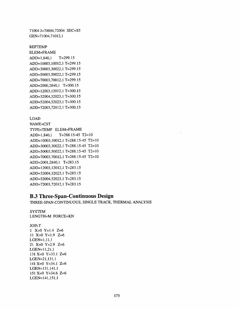
71004 J=70004,72004 SEC=S5
GEN=71004,71012,1
REFTEMP
ELEM=FRAME
ADD=1,840,1 T=299.15
ADD= 10003,10012,1 T=299.15
ADD=30003,30022,1 T=299.15
ADD=50003,50022,1 T=299.15
ADD=70003,70012,1 T=299.15
ADD=2000,2840,1 T=300.15
ADD=12003,12012,1 T=300.15
ADD=32004,32023,1 T=300.15
ADD=52004,52023,1 T=300.15
ADD=72003,72012,1 T=300.15
LOAD
NAME=CST
TYPE=TEMP ELEM=FRAME
ADD=1,840,1 T=288.15-45 T2=10
ADD=10003,10012,1 T=288.15-45 T2=10
ADD=30003,30022,1 T=288.15-45 T2=10
ADD=50003,50022,1 T=288.15-45 T2=10
ADD=70003,70012,1 T=288.15-45 T2=10
ADD=2001,2840,1 T=283.15
ADD=12003,12012,1 T=283.15
ADD=32004,32023,1 T=283.15
ADD=52004,52023,1 T=283.15
ADD=72003,72012,1 T=283.15
B.3 Three-Span-Continuous DesignTHREE-SPAN-CONTINUOUS, SINGLE TRACK, THERMAL ANALYSIS
SYSTEMLENGTH=M FORCE=KN
JOINT1 X=0 Y=1.4 Z=611 X=0 Y=1.9 Z=6LGEN= 1,11,121 X=0 Y=2.9 Z=6LGEN= 11,21,1131 X=0 Y=33.1 Z=6LGEN=21,131,1141 X=0 Y=34.1 Z=6LGEN= 131,141,1151 X=0 Y=34.6 Z=6LGEN=141,151,1
175
152 X=0 Y=37.4 Z=6162 X=0 Y=37.9 Z=6LGEN=152,162,1172 X=0 Y=39.9 Z=6LGEN=162,172,1282 X=0 Y=69.1 Z=6LGEN=172,282,1292 X=0 Y=70.1 Z=6LGEN=282,292,1302 X=0 Y=70.6 Z=6LGEN=292,302,1303 X=0 Y=73.4 Z=6313 X=0 Y=73.9 Z-6LGEN=303,313,1323 X=0 Y=74.9 Z=6LGEN=313,323,1433 X=O Y=105.1 Z=6LGEN=323,433,1443 X=0 Y=106.1 Z=6LGEN=433,443,1453 X=0 Y=106.6 Z=6LGEN=443,453,1454 X=0 Y= 109.4 Z=6464 X=0 Y=109.9 Z-6LGEN=454,464,1474 X=0 Y=110.9 Z=6LGEN=464,474, 1584 X=0 Y=141.1 Z=6LGEN=474,584,1594 X=0 Y=142.1 Z=6LGEN=584,594,1604 X=0 Y=142.6 Z=6LGEN=594,604,1605 X=0 Y= 145.4 Z=6615 X=0 Y=145.9 Z=6LGEN=605,615,1625 X=0 Y=146.9 Z=6LGEN=615,625,1735 X=O Y=177.1 Z=6LGEN=625,735,1745 X=0 Y=178.1 Z=6LGEN=735,745,1755 X=O Y=178.6 Z=6LGEN=745,755,1756 X=0 Y=181.4 Z=6766 X=0 Y=181.9 Z=6LGEN=756,766,1776 X=0 Y= 182.9 Z=6LGEN=766,776,1886 X=0 Y=213.1 Z=6LGEN=776,886,1896 X=0 Y=214.1 Z-=6LGEN=886,896,1906 X=0 Y=214.6 Z=6
176

LGEN=896,906,1
2001 X=0 Y=1.4 Z-=6.42011 X=0 Y=1.9 Z-=6.4LGEN=2001,2011,12021 X=0 Y=2.9 Z-=6.4LGEN=2011,2021,12131 X=0 Y=33.1 Z-=6.4LGEN=2021,2131,12141 X=0 Y=34.1 Z-=6.4LGEN=2131,2141,12151 X=0 Y=34.6 Z-=6.4LGEN=2141,2151,12152 X=0 Y=37.4 Z-=6.42162 X=0 Y=37.9 Z-=6.4LGEN=2152,2162,12172 X=0 Y=39.9 Z-=6.4LGEN=2162,2172,12282 X=0 Y=69.1 Z-=6.4LGEN=2172,2282,12292 X=0 Y=70.1 Z-=6.4LGEN=2282,2292,12302 X=0 Y=70.6 Z-=6.4LGEN=2292,2302,12303 X=0 Y=73.4 Z-=6.42313 X=0 Y=73.9 Z-=6.4LGEN=2303,2313,12323 X=0 Y=74.9 Z-=6.4LGEN=2313,2323,12433 X=0 Y=105.1 Z-=6.4LGEN=2323,2433,12443 X=0 Y= 106.1 Z-=6.4LGEN=2433,2443,12453 X=0 Y=106.6 Z-6.4LGEN=2443,2453,12454 X=0 Y=109.4 Z-=6.42464 X=0 Y=109.9 Z-6.4LGEN=2454,2464,12474 X=0 Y=110.9 Z-=6.4LGEN=2464,2474,12584 X=0 Y=141.1 Z-=6.4LGEN=2474,2584,12594 X=0 Y=142.1 Z-=6.4LGEN=2584,2594,12604 X=0 Y= 142.6 Z-=6.4LGEN=2594,2604,12605 X=0 Y= 145.4 Z-6.42615 X=0 Y= 145.9 Z-6.4LGEN=2605,2615,12625 X=0 Y=146.9 Z-6.4LGEN=2615,2625,12735 X=0 Y=177.1 Z-=6.4LGEN=2625,2735,12745 X=0 Y=178.1 Z-=6.4
177
LGEN=2735,2745,12755 X=0 Y=178.6 Z=6.4LGEN=2745,2755,12756 X=0 Y= 181.4 Z=6.42766 X=0 Y= 181.9 Z=6.4LGEN=2756,2766, 12776 X=0 Y=182.9 Z=6.4LGEN=2766,2776,12886 X=0 Y=213.1 Z=6.4LGEN=2776,2886, 12896 X=0 Y=214.1 Z=6.4LGEN=2886,2896,12906 X=0 Y=214.6 Z=6.4LGEN=2896,2906,1
10003 X=0 Y=0 Z=5.910013 X=0 Y=1.4 Z=5.9LGEN= 10003,10013,110014 X=0 Y=1.4 Z=620002 X=0 Y=36 Z-020003 X=O Y=36 Z=620004 X=0 Y=34.6 Z=620024 X=0 Y=37.4 Z=6LGEN=20004,20024,130002 X=0 Y=72 Z=030003 X=0 Y=72 Z=630004 X=0 Y=70.6 Z=630024 X=0 Y=73.4 Z=6LGEN=30004,30024,140002 X=0 Y=108 Z=040003 X=0 Y=108 Z-=5.940004 X=0 Y=106.6 Z=5.940024 X=0 Y= 109.4 Z-=5.9LGEN=40004,40024,140025 X=0 Y=106.6 Z-=640026 X=0 Y= 109.4 Z-650002 X=0 Y= 144 Z=050003 X=0 Y=144 Z=650004 X=0 Y=142.6 Z=650024 X=0 Y=145.4 Z=6LGEN=50004,50024,160002 X=0 Y=180 Z=060003 X=0 Y=180 Z=660004 X=0 Y=178.6 Z=660024 X=0 Y=181.4 Z=6LGEN=60004,60024,170003 X=0 Y=216 Z-=5.970013 X=0 Y=214.6 Z=5.9LGEN=70003,70013,170014 X=0 Y=214.6 Z=6
12003 X=0 Y=0 Z-=6.412013 X=0 Y=1.4 Z-=6.4LGEN= 12003,12013,1
178

22004 X=O Y=34.6 Z=6.422024 X=0 Y=37.4 Z=6.4LGEN=22004,22024, I132004 X=0 Y=70.6 Z=6.432024 X=0 Y=73.4 Z=6.4LGEN=32004,32024,142004 X=0 Y=106.6 Z=6.442024 X=0 Y=109.4 Z=6.4LGEN=42004,42024,152004 X=0 Y=142.6 Z=6.452024 X=0 Y=145.4 Z=6.4LGEN=52004,52024,162004 X=0 Y=178.6 Z=6.462024 X=0 Y=181.4 Z=6.4LGEN=62004,62024,172003 X=0 Y=216 Z=6.472013 X=0 Y=214.6 Z=6.4LGEN=72003,72013,1
RESTRAINTADD=20002,60002, 10000 DOF=ALLADD= 12003,72003,60000 DOF=ALLADD= 10003,70003,60000 DOF=ALL
WELDNAME=ALL TOL=0.000001ADD=*
MATERIALNAME=BEAM TYPE=ISO M=2.4 W=23.544E=27670000 U=0.30 A=0.000011NAME=COLUMN TYPE=ISO M=2.4 W=23.544E=23420000 U=0.25NAME=TBEAM TYPE=ISOE=27670000 U=0.30 A=0.000011NAME=ELASTO TYPE=ORTHOE=1284349,1284349,1284349 G=1400,1400,1400NAME=RAIL TYPE=ISOE=2.1E8 U=0.30 A=12E-6NAME=RSPRING TYPE=ISOE=8000
FRAME SECTIONNAME=ONE TYPE=PRISM MAT=BEAM A=4.2374 J=1.054 1=.43567,7.1614AS=2.862,3.2669NAME=TWO TYPE=PRISM MAT=BEAM A=6.6136 J=3.883 1=2.8134,9.1271AS=2.900,3.480NAME=THREE TYPE=PRISM MAT=BEAM A=3.0664 J=2.976 1=1.8551,6.8861AS=1.175,1.460NAME=FOUR TYPE=PRISM MAT=BEAM A=6.9040 J=4.076 1=2.9480,9.1760AS=3.183,3.850NAME=COLFIX TYPE=PRISM MAT=COLUMN SH=P T=1.83NAME=COLEXP TYPE=PRISM MAT=COLUMN SH=P T=1.83NAME=LINK TYPE=PRISM MAT=TBEAM A=1000 J=1000 I=1000,1000
179

AS= 1000, 1000NAME=BEARING TYPE=PRISM MAT=ELASTO SH=R T=2*0.85,0.85NAME=S1 TYPE=PRISM MAT=RSPRING A=1000 I=0.5/10/187.5J= 1000NAME=S2 TYPE=PRISM MAT=RSPRING A=1000 1=1/10/187.5J=1000NAME=S3 TYPE=PRISM MAT=RSPRING A=1000 1=32.1/110/187.5J= 1000NAME=S4 TYPE=PRISM MAT=RSPRING A=1000 I=1/10/187.5J= 1000NAME=S5 TYPE=PRISM MAT=RSPRING A=1000 I=1.4/10/96J= 1000NAME=RAIL TYPE=PRISM MAT=RAIL A=2*7257.34/1000/1000 I=2*27304781.52/1000/1000/1000/1000
FRAME1 J=1,2 SEC=ONEGEN= 1,10,111 J=11,12 SEC=TWOGEN= 11,20,121 J=21,22 SEC=THREEGEN=21,130,1131 J=131,132 SEC=THREEGEN=131,140,1141 J=141,142 SEC=THREEGEN=141,150,1151 J=152,153 SEC=THREEGEN=151,160,1161 J=162,163 SEC=THREEGEN=161,170,1171 J=172,173 SEC=THREEGEN=171,280,1281 J=282,283 SEC=THREEGEN=281,290,1291 J=292,293 SEC=THREEGEN=291,300,1301 J=303,304 SEC=THREEGEN=301,310,1311 J=313,314 SEC=THREEGEN=311,320,1321 J=323,324 SEC=THREEGEN=321,430,1431 J=433,434 SEC=TWOGEN=431,440,1441 J=443,444 SEC=ONEGEN=441,450,1451 J=454,455 SEC=ONEGEN=451,460,1461 J=464,465 SEC=TWOGEN=461,470,1471 J=474,475 SEC=THREEGEN=471,580,1581 J=584,585 SEC=THREEGEN=581,590,1
180

591 J=594,595 SEC=THREEGEN=591,600,1601 J=605,606 SEC=THREEGEN=601,610,1611 J=615,616 SEC=THREEGEN=611,620,1621 J=625,626 SEC=THREEGEN=621,730,1731 J=735,736 SEC=THREEGEN=73 1,740,1741 J=745,746 SEC=THREEGEN=741,750,1751 J=756,757 SEC=THREEGEN=751,760,1761 J=766,767 SEC=THREEGEN=761,770,1771 J=776,777 SEC=THREEGEN=771,880,1881 J=886,887 SEC=TWOGEN=881,890,1891 J=896,897 SEC=ONEGEN=891,900,1
2001 J=2001,2002 SEC=RAILGEN=2001,2010,12011 J=2011,2012 SEC=RAILGEN=2011,2020,12021 J=2021,2022 SEC=RAILGEN=2021,2130,12131 J=2131,2132 SEC=RAILGEN=2131,2140,12141 J=2141,2142 SEC=RAILGEN=2141,2150,12151 J=2152,2153 SEC=RAILGEN=2151,2160,12161 J=2162,2163 SEC=RAILGEN=2161,2170,12171 J=2172,2173 SEC=RAILGEN=2171,2280,12281 J=2282,2283 SEC=RAILGEN=2281,2290,12291 J=2292,2293 SEC=RAILGEN=2291,2300,12301 J=2303,2304 SEC=RAILGEN=2301,2310,12311 J=2313,2314 SEC=RAILGEN=2311,2320,12321 J=2323,2324 SEC=RAILGEN=2321,2430,12431 J=2433,2434 SEC=RAILGEN=2431,2440,12441 J=2443,2444 SEC=RAILGEN=2441 ,2450,12451 J=2454,2455 SEC=RAIL

GEN=2451,2460,12461 J=2464,2465 SEC=RAILGEN=2461,2470,12471 J=2474,2475 SEC=RAILGEN=2471,2580,12581 J=2584,2585 SEC=RAILGEN=2581,2590,12591 J=2594,2595 SEC=RAILGEN=2591,2600,12601 J=2605,2606 SEC=RAILGEN=2601,2610,12611 J=2615,2616 SEC=RAILGEN=2611,2620,12621 J=2625,2626 SEC=RAILGEN=2621,2730,12731 J=2735,2736 SEC=RAILGEN=2731,2740,12741 J=2745,2746 SEC=RAILGEN=2741,2750,12751 J=2756,2757 SEC=RAILGEN=2751,2760,12761 J=2766,2767 SEC=RAILGEN=2761,2770,12771 J=2776,2777 SEC=RAILGEN=2771,2880,12881 J=2886,2887 SEC=RAILGEN=2881,2890,12891 J=2896,2897 SEC=RAILGEN=2891,2900,1
12003 J=12003,12004 SEC=RAILGEN=12003,12012,122004 J=22004,22005 SEC=RAILGEN=22004,22023,132004 J=32004,32005 SEC=RAILGEN=32004,32023,142004 J=42004,42005 SEC=RAILGEN=42004,42023,152004 J=52004,52005 SEC=RAILGEN=52004,52023,162004 J=62004,62005 SEC=RAILGEN=62004,62023,172003 J=72003,72004 SEC=RAILGEN=72003,72012,1
10003 J=10003,10004 SEC=LINKGEN= 10003,10012,110013 J=10013,10014 SEC=BEARING20002 J=20002,20003 SEC=COLFIX20003 J=20004,20005 SEC=THREEGEN=20003,20009,120010 J=20011,20012 SEC=FOURGEN=20010,20015,120016 J=20017,20018 SEC=THREE
182

GEN=20016,20022,130002 J=30002,30003 SEC=COLF30003 J=30004,30005 SEC=THREGEN=30003,30009, 130010 J=30011,30012 SEC=FOURGEN=30010,30015,130016 J=30017,30018 SEC=THREGEN=30016,30022,140002 J=40002,40003 SEC=COLE40003 J=40004,40005 SEC=LINKGEN=40003,40022,140023 J=40004,40025 SEC=BEAR40024 J=40024,40026 SEC=BEAR50002 J=50002,50003 SEC=COLF50003 J=50004,50005 SEC=THREGEN=50003,50009,150010 J=50011,50012 SEC=FOURGEN=50010,50015,150016 J=50017,50018 SEC=THREGEN=50016,50022,160002 J=60002,60003 SEC=COLF60003 J=60004,60005 SEC=THREGEN=60003,60009,160010 J=60011,60012 SEC=FOURGEN=60010,60015,160016 J=60017,60018 SEC=THREGEN=60016,60022,170003 J=70003,70004 SEC=LINKGEN=70003,70012,170013 J=70013,70014 SEC=BEAR
1001 J=1,2001 SEC=S 1GEN=1001,1011,11012 J=12,2012 SEC=S2GEN=1012,1021,11022 J=22,2022 SEC=S3GEN=1022,1131,11132 J=132,2132 SEC=S2GEN=1132,1141,11142 J=142,2142 SEC=S IGEN=1142,1151,11152 J=152,2152 SEC=S1GEN=1152,1162,11163 J=163,2163 SEC=S2GEN=1163,1172,11173 J=173.2173 SEC=S3GEN= 1173,1302,11283 J=283,2283 SEC=S2GEN=1283,1292,11293 J=293,2293 SEC=S 1GEN= 1293,1302,11303 J=303,2303 SEC=S 1GEN= 1303,1313,11314 J=314,2314 SEC=S2
IXE
E
XP
INGINGIXE
E
IXE
E
ING
183

GEN=1314,1323,11324 J=324,2324 SEC=S3GEN=1324,1433,11434 J=434,2434 SEC=S2GEN=1434,1443,11444 J=444,2444 SEC=S 1GEN= 1444,1453,11454 J=454,2454 SEC=SIGEN= 1454,1464,11465 J=465,2465 SEC=S2GEN= 1465,1474,11475 J=475,2475 SEC=S3GEN=1475,1584,11585 J=585,2585 SEC=S2GEN=1585,1594,11595 J=595,2595 SEC=S IGEN=1595,1604,11605 J=605,2605 SEC=S 1GEN=1605,1615,11616 J=616,2616 SEC=S2GEN=1616,1625,11626 J=626,2626 SEC=S3GEN= 1626,1735,11736 J=736,2736 SEC=S2GEN= 1736,1745,11746 J=746,2746 SEC=S1GEN= 1746,1755,11756 J=756,2756 SEC=SIGEN= 1756,1766,11767 J=767,2767 SEC=S2GEN=1767,1776,11777 J=777,2777 SEC=S3GEN=1777,1886,11887 J=887,2887 SEC=S2GEN= 1887,1896,11897 J=897,2897 SEC=S 1GEN= 1897,1906,1
11004 J=10004,12004 SEC=S5GEN=11004,11012,121005 J=20005,22005 SEC=S5GEN=21005,21023,131005 J=30005,32005 SEC=S5GEN=3 1005,31023,141005 J=40005,42005 SEC=S5GEN=41005,41023,151005 J=50005,52005 SEC=S5GEN=51005,51023,161005 J=60005,62005 SEC=S5GEN=61005,61023,171004 J=70004,72004 SEC=S5GEN=71004,71012,1
REFTEMP
184

ELEM=FRAMEADD= 1,900,1 T=299.15ADD=10003,10012,1 T=299.15ADD=20003,20012,1 T=299.15ADD=20013,20022,1 T=299.15ADD=30003,30012,1 T=299.15ADD=30013,30022,1 T=299.15ADD=40003,40012,1 T=299.15ADD=40013,40022,1 T=299.15ADD=50003,50012,1 T=299.15ADD=50013,50022,1 T=299.15ADD=60003,60012,1 T=299.15ADD=60013,60022,1 T=299.15ADD=70003,70012,1 T=299.15ADD=2001,2900,1 T=300.15ADD= 12003,12012,1 T=300.15ADD=22003,22012,1 T=300.15ADD=32004,32023,1 T=300.15ADD=42003,42012,1 T=300.15ADD=52004,52023,1 T=300.15ADD=62003,62012,1 T=300.15ADD=72003,72012,1 T=300.15
LOADNAME=CSTTYPE=TEMP ELEM=FRAMEADD=1,150,1 T=288.15-45 T2=10ADD=151,300,1 T=288.15-45 T2=10ADD=301,450,1 T=288.15-45 T2=10ADD=451,600,1 T=288.15-45 T2=10ADD=601,750,1 T=288.15-45 T2=10ADD=751,900,1 T=288.15-45 T2=10ADD=10003,10012,1 T=288.15-45 T2=10ADD=20003,20012,1 T=288.15-45 T2=10ADD=20013,20022,1 T=288.15-45 T2=10ADD=30003,30012,1 T=288.15-45 T2=10ADD=30013,30022,1 T=288.15-45 T2=10ADD=40003,40012,1 T=288.15-45 T2=10ADD=40013,40022,1 T=288.15-45 T2=10ADD=50003,50012,1 T=288.15-45 T2=10ADD=50013,50022,1 T=288.15-45 T2=10ADD=60003,60012,1 T=288.15-45 T2=10ADD=60013,60022,1 T=288.15-45 T2=10ADD=70003,70012,1 T=288.15-45 T2=10ADD=2001,2900,1 T=283.15ADD=12003,12012,1 T=283.15ADD=22003,22012,1 T=283.15ADD=32004,32023,1 T=283.15ADD=42003,42012,1 T=283.15ADD=52004,52023,1 T=283.15ADD=62003,62012,1 T=283.15ADD=72003,72012,1 T=283.15
185

B.4 Four-Span-Continuous DesignFOUR-SPAN-CONTINUOUS
SYSTEMLENGTH=M FORCE=KN
JOINT1 X=O Y=1.4 Z=611 X=0 Y=1.9 Z=6LGEN= 1,11,121 X=0 Y=2.9 Z=6LGEN= 11,21,1131 X=0 Y=35 Z=6LGEN=21,131,1141 X=0 Y=36 Z=6LGEN=131,141,1151 X=0 Y=37 Z=6LGEN=141,151,1261 X=0 Y=69.1 Z=6LGEN=151,261,1271 X=0 Y=70.1 Z=6LGEN=261,271,1281 X=0 Y=70.6 Z=6LGEN=271,281,1282 X=0 Y=73.4 Z=6292 X=0 Y=73.9 Z=6LGEN=282,292,1302 X=O Y=74.9 Z=6LGEN=292,302, 1412 X=O Y= 107 Z=6LGEN=302,412,1422 X=O Y=108 Z=6LGEN=412,422,1432 X=0 Y=109 Z=6LGEN=422,432,1542 X=0 Y=141.1 Z=6LGEN=432,542, 1552 X=0 Y=142.1 Z=6LGEN=542,552, 1562 X=0 Y=142.6 Z=6LGEN=552,562, 1563 X=0 Y=145.4 Z=6573 X=0 Y=145.9 Z=6LGEN=563,573,1583 X=0 Y=146.9 Z=6LGEN=573,583,1693 X=O Y=179 Z=6LGEN=583,693,1703 X=0 Y=180 Z=6LGEN=693,703,1713 X=0 Y=181 Z=6LGEN=703,713,1823 X=0 Y=213.1 Z=6
186

LGEN=713,823,1833 X=O Y=214.1 Z=6LGEN=823,833,1843 X=0 Y=214.6 Z=6LGEN=833,843,1
2001 X=0 Y=1.4 Z=-6.42011 X=O Y=1.9 Z=6.4LGEN=2001,2011,12021 X=0 Y=2.9 Z=-6.4LGEN=2011,2021,12131 X=0 Y=35 Z=-6.4LGEN=2021,2131,12141 X=0 Y=36 Z=-6.4LGEN=2131,2141,12151 X=0 Y=37 Z=6.4LGEN=2141,2151,12261 X=0 Y=69.1 Z=6.4LGEN=2151,2261,12271 X=0 Y=70.1 Z=6.4LGEN=2261,2271,12281 X=0 Y=70.6 Z=6.4LGEN=2271,2281,12282 X=0 Y=73.4 Z=6.42292 X=0 Y=73.9 Z=6.4LGEN=2282,2292,12302 X=0 Y=74.9 Z=6.4LGEN=2292,2302,12412 X=0 Y=107 Z=6.4LGEN=2302,2412,12422 X=0 Y=108 Z=6.4LGEN=2412,2422,12432 X=0 Y=109 Z-=6.4LGEN=2422,2432, 12542 X=0 Y=141.1 Z=6.4LGEN=2432,2542, 12552 X=0 Y=142.1 Z=6.4LGEN=2542,2552,12562 X=0 Y=142.6 Z=6.4LGEN=2552,2562,12563 X=0 Y=145.4 Z=6.42573 X=0 Y= 145.9 Z=6.4LGEN=2563,2573,12583 X=0 Y=146.9 Z-=6.4LGEN=2573,2583,12693 X=0 Y=179 Z=6.4LGEN=2583,2693,12703 X=0 Y=180 Z=-6.4LGEN=2693,2703,12713 X=0 Y=181 Z-=6.4LGEN=2703,2713,12823 X=0 Y=213.1 Z-6.4LGEN=2713,2823,12833 X=0 Y=214.1 Z-6.4
187
LGEN=2823,2833,12843 X=0 Y=214.6 Z-6.4LGEN=2833,2843,1
10003 X=0 Y=0 Z=5.910013 X=0 Y=1.4 Z=5.9LGEN= 10003,10013,110014 X=0 Y=1.4 Z=620002 X=O Y=36 Z=020003 X=O Y=36 Z=630002 X=0 Y=72 Z=-030003 X=0 Y=72 Z=630004 X=0 Y=70.6 Z=-630024 X=0 Y=73.4 Z=6LGEN=30004,30024,140002 X=0 Y=108 Z=040003 X=0 Y=108 Z=650002 X=0 Y=144 Z=050003 X=0 Y=144 Z=5.950004 X=0 Y=142.6 Z=-5.950024 X=0 Y=145.4 Z=5.9LGEN=50004,50024,150025 X=0 Y=142.6 Z=650026 X=0 Y= 145.4 Z=660002 X=0 Y=180 Z=060003 X=0 Y=180 Z=670003 X=0 Y=216 Z=5.970013 X=0 Y=214.6 Z=5.9LGEN=70003,70013,170014 X=0 Y=214.6 Z=6
12003 X=0 Y=0 Z=6.412013 X=0 Y=1.4 Z=6.4LGEN= 12003,12013,132004 X=0 Y=70.6 Z=6.432024 X=0 Y=73.4 Z=6.4LGEN=32004,32024,152004 X=0 Y=142.6 Z=6.452024 X=0 Y=145.4 Z=-6.4LGEN=52004,52024,172003 X=0 Y=216 Z=6.472013 X=0 Y=214.6 Z=-6.4LGEN=72003,72013,1
RESTRAINTADD=20002,60002,10000 DOF=ALLADD= 12003,72003,60000 DOF=ALLADD= 10003,70003,60000 DOF=ALL
WELDNAME=ALL TOL=0.000001ADD=*
MATERIAL
188

NAME=BEAM TYPE=ISO M=2.4 W=23.544E=34970000 U=0.30 A=0.000011NAME=COLUMN TYPE=ISO M=2.4 W=23.544E=27670000 U=0.25NAME=TBEAM TYPE=ISOE=34970000 U=0.30 A=0.000011NAME=ELASTO TYPE=ORTHOE= 1496953,1496953,1496953 G=1400,1400,1400NAME=ELASTO2 TYPE=ORTHOE=898736,898736,898736 G=1400,1400,1400NAME=RAIL TYPE=ISOE=2.1E8 U=0.30 A=12E-6NAME=RSPRING TYPE=ISOE=8000
FRAME SECTIONNAME=ONE TYPE=PRISM MAT=BEAM A=4.2374 J=1.054 I=.43567,7.1614AS=2.862,3.2669NAME=TWO TYPE=PRISM MAT=BEAM A=6.6136 J=3.883 1=2.8134,9.1271AS=2.900,3.480NAME=THREE TYPE=PRISM MAT=BEAM A=3.0664 J=2.976 1=1.8551,6.8861AS= 1.175,1.460NAME=FOUR TYPE=PRISM MAT=BEAM A=6.9040 J=4.076 1=2.9480,9.1760AS=3.183,3.850NAME=COLFIX TYPE=PRISM MAT=COLUMN SH=P T=1.83NAME=COLEXP TYPE=PRISM MAT=COLUMN SH=P T=1.83NAME=LINK TYPE=PRISM MAT=TBEAM A=1000 J=1000 I=1000,1000AS= 1000, 1000NAME=BEARING TYPE=PRISM MAT=ELASTO SH=R T=2*1.05,1.05NAME=BEARING2 TYPE=PRISM MAT=ELASTO2 SH=R T=2*0.55,0.60NAME=S 1 TYPE=PRISM MAT=RSPRING A=1000 1=0.5/10/187.5J= 1000NAME=S2 TYPE=PRISM MAT=RSPRING A=1000 I=1/10/187.5J=1000NAME=S3 TYPE=PRISM MAT=RSPRING A=1000 1=32.1/110/187.5J= 1000NAME=S4 TYPE=PRISM MAT=RSPRING A=1000 I=1/10/187.5J= 1000NAME=S5 TYPE=PRISM MAT=RSPRING A=1000 1=1.4/10/96J= 1000NAME=RAIL TYPE=PRISM MAT=RAIL A=2*7257.34/1000/1000 I=2*27304781.52/1000/1000/1000/1000
FRAME1 J=1,2 SEC=ONEGEN= 1,10, 111 J= 1,12 SEC=TWOGEN= 11,20,121 J=21,22 SEC=THREEGEN=21,130,1131 J=131,132 SEC=FOURGEN=131,150,1151 J=151,152 SEC=THREEGEN= 151,260,1
189

261 J=261,262 SEC=THREEGEN=261,270,1271 J=271,272 SEC=THREEGEN=271,280,1281 J=282,283 SEC=THREEGEN=281,290,1291 J=292,293 SEC=THREEGEN=291,300,1301 J=302,303 SEC=THREEGEN=301,410,1411 J=412,413 SEC=FOURGEN=411,430,1431 J=432,433 SEC=THREEGEN=431,540,1541 J=542,543 SEC=TWOGEN=541,550,1551 J=552,553 SEC=ONEGEN=551,560,1561 J=563,564 SEC=ONEGEN=561,570,1571 J=573,574 SEC=TWOGEN=571,580,1581 J=583,584 SEC=THREEGEN=58 1,690,1691 J=693,694 SEC=FOURGEN=691,710,1711 J=713,714 SEC=THREEGEN=711,820,1821 J=823,824 SEC=TWOGEN=821,830,1831 J=833,834 SEC=ONEGEN=831,840,1
2001 J=2001,2002 SEC=RAILGEN=2001,2010,12011 J=2011,2012 SEC=RAILGEN=2011,2020,12021 J=2021,2022 SEC=RAILGEN=2021,2130,12131 J=2131,2132 SEC=RAILGEN=2131,2150,12151 J=2151,2152 SEC=RAILGEN=2151,2260,12261 J=2261,2262 SEC=RAILGEN=2261,2270,12271 J=2271,2272 SEC=RAILGEN=2271,2280,12281 J=2282,2283 SEC=RAILGEN=2281,2290,12291 J=2292,2293 SEC=RAILGEN=2291,2300,12301 J=2302,2303 SEC=RAILGEN=2301,2410,12411 J=2412,2413 SEC=RAIL
190

GEN=2411,2430,12431 J=2432,2433 SEC=RAILGEN=2431,2540,12541 J=2542,2543 SEC=RAILGEN=2541,2550,12551 J=2552,2553 SEC=RAILGEN=2551,2560,12561 J=2563,2564 SEC=RAILGEN=2561,2570,12571 J=2573,2574 SEC=RAILGEN=2571,2580, 12581 J=2583,2584 SEC=RAILGEN=2581,2690,12691 J=2693,2694 SEC=RAILGEN=2691,2710,12711 J=2713,2714 SEC=RAILGEN=2711,2820,12821 J=2823,2824 SEC=RAILGEN=2821,2830,12831 J=2833,2834 SEC=RAILGEN=2831,2840,1
12003 J=12003,12004 SEC=RAILGEN=12003,12012,132004 J=32004,32005 SEC=RAILGEN=32004,32023,152004 J=52004,52005 SEC=RAILGEN=52004,52023,172003 J=72003,72004 SEC=RAILGEN=72003,72012,1
10003 J=10003,10004 SEC=LINKGEN=10003,10012,110013 J=10013,10014 SEC=BEARING20002 J=20002,20003 SEC=COLFIX30002 J=30002,30003 SEC=COLFIX30003 J=30004,30005 SEC=THREEGEN=30003,30009, 130010 J=30011,30012 SEC=FOURGEN=30010,30015,130016 J=30017,30018 SEC=THREEGEN=30016,30022, 140002 J=40002,40003 SEC=COLFIX50002 J=50002,50003 SEC=COLEXP50003 J=50004,50005 SEC=LINKGEN=50003,50022,150023 J=50004,50025 SEC=BEARING50024 J=50024,50026 SEC=BEARING260002 J=60002,60003 SEC=COLFIX70003 J=70003,70004 SEC=LINKGEN=70003,70012,170013 J=70013,70014 SEC=BEARING2
1001 J=1,2001 SEC=S1

GEN=1001,1011,11012 J=12,2012 SEC=S2GEN=1012,1021,11022 J=22,2022 SEC=S3GEN= 1022, 113 1,11132 J=132,2132 SEC=S4GEN=1132,1151,11152 J=152,2152 SEC=S3GEN=1152,1261,11262 J=262,2262 SEC=S2GEN=1262,1271,11272 J=272,2272 SEC=S1GEN=1272,1281,11282 J=282,2282 SEC=S1GEN= 1282,1292,11293 J=293,2293 SEC=S2GEN=1293,1302,11303 J=303,2303 SEC=S3GEN=1303,1412,11413 J=413,2413 SEC=S4GEN=1413,1432,11433 J=433,2433 SEC=S3GEN= 1433,1542,11543 J=543,2543 SEC=S2GEN= 1543,1552,11553 J=553,2553 SEC=S 1GEN= 1553,1562,11563 J=563,2563 SEC=S 1GEN= 1563,1573,11574 J=574,2574 SEC=S2GEN=1574,1583,11584 J=584,2584 SEC=S3GEN=1584,1693,11694 J=694,2694 SEC=S4GEN=1694,1713,11714 J=714,2714 SEC=S3GEN=1714,1823,11824 J=824,2824 SEC=S2GEN=1824,1833,11834 J=834,2834 SEC=S 1GEN=1834,1843,1
11004 J=10004,12004 SEC=S5GEN=11004,11012,131005 J=30005,32005 SEC=S5GEN=31005,31023,151005 J=50005,52005 SEC=S5GEN=51005,51023,171004 J=70004,72004 SEC=S5GEN=71004,71012,1
REFTEMPELEM=FRAMEADD=1,840,1 T=299.15
192
ADD= 10003,10012,1 T=299.15ADD=30003,30012,1 T=299.15ADD=30013,30022,1 T=299.15ADD=50003,50012,1 T=299.15ADD=50013,50022,1 T=299.15ADD=70003,70012,1 T=299.15ADD=2000,2840,1 T=300.15ADD= 12003,12012,1 T=300.15ADD=32004,32023,1 T=300.15ADD=52004,52023,1 T=300.15ADD=72003,72012,1 T=300.15
LOADNAME=CSTTYPE=TEMP ELEM=FRAMEADD=1,140,1 T=288.15-45 T2=10ADD=141,280,1 T=288.15-45 T2=10ADD=281,420,1 T=288.15-45 T2=10ADD=421,560,1 T=288.15-45 T2=10ADD=561,700,1 T=288.15-45 T2=10ADD=701,840,1 T=288.15-45 T2=10ADD=10003,10012,1 T=288.15-45 T2=10ADD=30003,30012,1 T=288.15-45 T2=10ADD=30013,30022,1 T=288.15-45 T2=10ADD=50003,50012,1 T=288.15-45 T2=10ADD=50013,50022,1 T=288.15-45 T2=10ADD=70003,70012,1 T=288.15-45 T2=10ADD=2000,2840,1 T=283.15ADD=12003,12012,1 T=283.15ADD=32004,32023,1 T=283.15ADD=52004,52023,1 T=283.15ADD=72003,72012,1 T=283.15

194

Appendix C
Elastomeric Bearings Properties
The bearings used in the Tren Urbano Project are laminated bearings comprising
various slabs of elastomer bonded to metal plates in sandwich form. These are sometimes
known as reinforced elastomeric bearings. The elastomer used is natural rubber, and the
metal is stainless steel.
For the analysis presented in Chapter 5, the thickness of all bearings was taken as 10
cm. The material and thickness taken for each of the layers are listed in Table C1.
Table CI: Material and thickness of layers of elastomeric bearings.
Layer No. Material Thickness (mm)
1 Steel 8
2 Rubber 5
3 Steel 4
4 Rubber 10
5 Steel 4
6 Rubber 10
7 Steel 4
8 Rubber 10
9 Steel 4
10 Rubber 10
11 Steel 4
12 Rubber 10
13 Steel 4
14 Rubber 5
15 Steel 8
195

To model the bearings in the analysis of Chapter 5, it was necessary to assign to the
bearing models a modulus of elasticity and a shear modulus. The rubber used in the bear-
ings has a hardness of 70 IRHD. The properties of this rubber are known: elastic modulus of
E = 6200 kN/m 2, a bulk modulus of Eb = 2,200,000 kN/m 2, and a shear modulus of G=
1400 kN/m 2 . Reinforcing the bearing with steel does not affect its shear modulus, but it
changes the elastic modulus. Therefore, the shear modulus given to the model is that of the
rubber.
The calculate the elastic modulus, first, the shape factor (S) is computed:
LBS=
2t(L + B)
where:
L = Length of the bearing;
B = width of the bearing;
t = thickness of an inner layer of elastomer (10 mm).
The purpose of adding steel to the bearing is to increase the shape factor. For exam-
ple, if the bearing of the analysis done for this research is not reinforced, then t would be
equal to 10 cm, and the shape factor would be greatly reduced.
Knowing the shape factor, the "apparent modulus" can be calculated:
Ea = E(1 + 2KS2 )
where K is an empirically determined constant (Long, 1974). For rubber with a hardness of
70 IRHD, K is equal to 0.55.
196

Finally, the effects of the bulk modulus of the elastomer have to be considered. The
"modified modulus is then computed:
EaEm-
Ea1+-Eb
The modified modulus was then taken as the elastic modulus of the bearing for the model
discussed in Chapter 5.
197

198

Appendix D
Column Design
For the model used in the analysis presented in Chapter 5, column dimensions of
length and diameter were given. Also given were properties of modulus of elasticity, den-
sity, and Poisson's ratio. This properties corresponded to a concrete of a certain strength f'c.
Once the loads that were acting on the column were known, it was necessary to determine
how much reinforcement the column required.
The steps taken to calculate the reinforcement were:
1. Check for slenderness effects. Slenderness effects have to be considered if:
kLu> 5.5h
where k is the effective length factor for compression members, Lu is the unsupported length
of the column, and h is the diameter of the column. The columns had to be checked for slen-
derness in both the longitudinal, and the transversal direction of the bridge. For the transver-
sal direction of the bridge is a good estimate to take k = 2. Using this value, it was always
found in the analysis that slenderness effects had to be considered.
2. Compute factor to approximate the effects of creep in the columns:
MdM
where Md is the moment produced by the dead load, and M is the maximum moment acting
in the column.
199
3. Compute the gross moment of inertia of the column:
nh 4
Ig =64
4. Compute flexural rigidity:
EcIg2.5El =
1 + pd
where Ec is the modulus of Elasticity of the concrete.
5. Compute critical buckling load:
P 2EIPc =
(kLu)2
6. Compute moment magnification factor:
12.5PPc
where P is the maximum axial load acting on the column.
7. Magnify P and M by mutiplying each by 5.
8. Compute P /f' and M / h Ag to use the appropiate interaction diagram prepared by the
American Concrete Institute (ACI) according to the strength of the concrete used, to the
reinforcing steel to be used, and to:
200
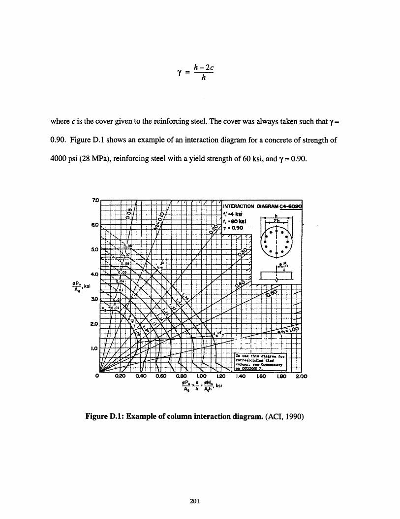
h-2c'Y- hh
where c is the cover given to the reinforcing steel. The cover was always taken such that y=
0.90. Figure D. 1 shows an example of an interaction diagram for a concrete of strength of
4000 psi (28 MPa), reinforcing steel with a yield strength of 60 ksi, and y = 0.90.
7.0
5.0
4.0
S ,ksiA,
0 020 0.40 0.60 0.80 1.00 1.20 1.40 1.60 1.80
Op. 0M- ksiA h Agh'
2.00
Figure D.1: Example of column interaction diagram. (ACI, 1990)
201
-- . .... ....INTERACTION DIAGRAM C4-
.............................. '-4 k s i
..,__._ _ 7 = .90 "".,. . .... .. ..i±. .....il
IN............................... ...--.. ... .. n1 1i
.. .... ............ .... ...... I ... .....
"
.... .--
-1
..... .. ..i 0. ... ..... .
_. d ran forc' i see- Commentary
. ... .... ..... .OTA COLUMNS

202
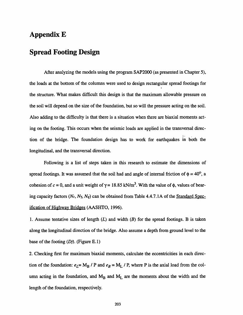
Appendix E
Spread Footing Design
After analyzing the models using the program SAP2000 (as presented in Chapter 5),
the loads at the bottom of the columns were used to design rectangular spread footings for
the structure. What makes difficult this design is that the maximum allowable pressure on
the soil will depend on the size of the foundation, but so will the pressure acting on the soil.
Also adding to the difficulty is that there is a situation when there are biaxial moments act-
ing on the footing. This occurs when the seismic loads are applied in the transversal direc-
tion of the bridge. The foundation design has to work for earthquakes in both the
longitudinal, and the transversal direction.
Following is a list of steps taken in this research to estimate the dimensions of
spread footings. It was assumed that the soil had and angle of internal friction of 4 = 400, a
cohesion of c = 0, and a unit weight of y = 18.85 kN/m3 . With the value of 4, values of bear-
ing capacity factors (Nc, Ny, Nq) can be obtained from Table 4.4.7.1A of the Standard Spec-
ification of Highway Bridges (AASHTO, 1996).
1. Assume tentative sizes of length (L) and width (B) for the spread footings. B is taken
along the longitudinal direction of the bridge. Also assume a depth from ground level to the
base of the footing (Df). (Figure E. 1)
2. Checking first for maximum biaxial moments, calculate the eccentricities in each direc-
tion of the foundation: eL= MB / P and eB = ML / P, where P is the axial load from the col-
umn acting in the foundation, and MB and ML are the moments about the width and the
length of the foundation, respectively.
203
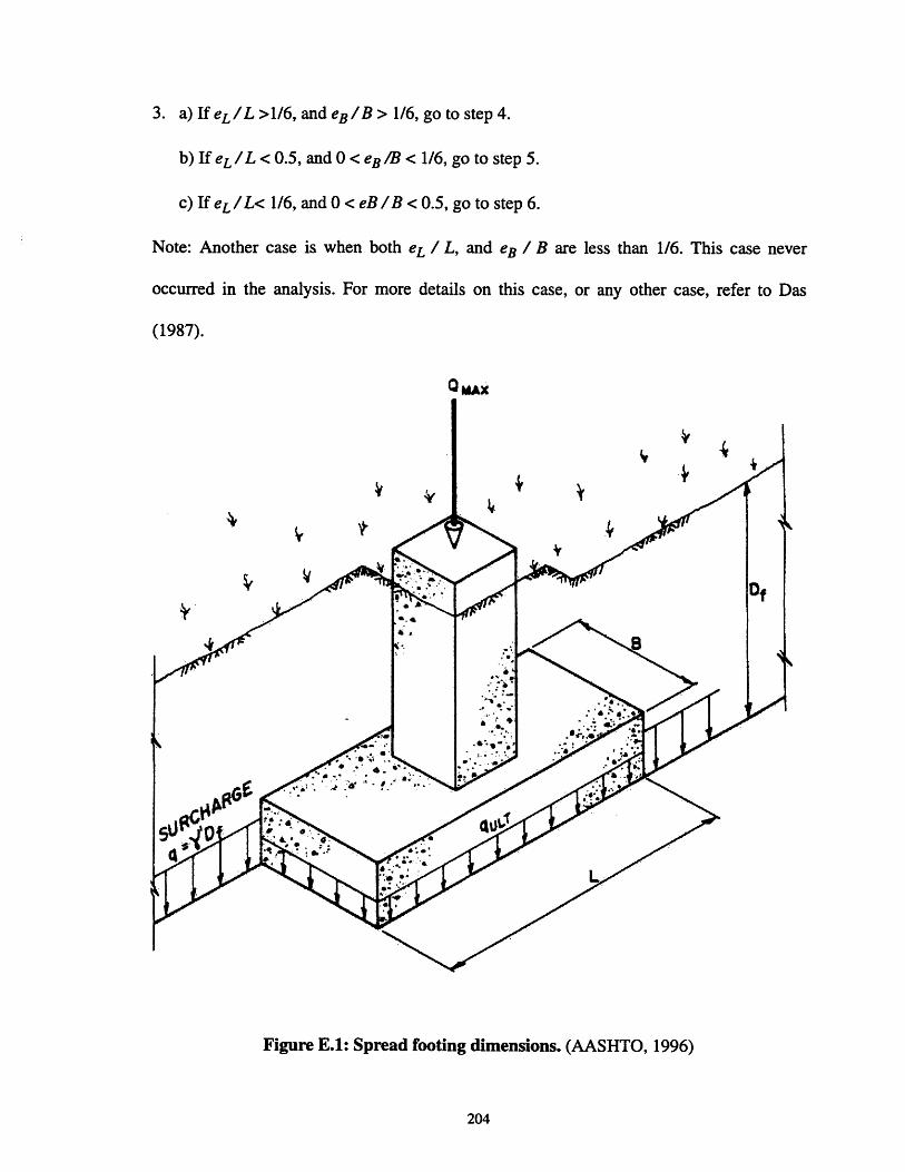
3. a) If eL /L >1/6, and eg / B > 1/6, go to step 4.
b) If eL /L < 0.5, and 0 < eg /B < 1/6, go to step 5.
c) If eL /L< 1/6, and 0 < eB /B < 0.5, go to step 6.
Note: Another case is when both eL / L, and eB / B are less than 1/6. This case never
occurred in the analysis. For more details on this case, or any other case, refer to Das
(1987).
Q LMAX
N.4
Figure E.1: Spread footing dimensions. (AASHTO, 1996)
204

4. This case corresponds to a pressure distribution shown in Figure E.2. Compute:
Bi = B(1.5 - )
Take smaller of B and L is taken as B, and the larger as L for steps 8 and 9. Go to step 7.
Take smaller of B1 and L1 is taken as B, and the larger as L for steps 8 and 9. Go to step 7.
B 1 Effectivearea
- B .
Figure E.2: Pressure distribution for eL / L >1/6, and eB / B > 1/6. (Das, 1987)
5. With values of eL /L and eB /B, obtain from Figure E.3 values of L 1 / L and L2 /L. Com-
pute:
1A = -(L1 + L2)B
2
AB1 = A
L1
205
i

where L1 is the larger of L1 and L2 . Take B 1 as B, and L1 as L for steps 8 and 9. Go to step 7.
6. With values of eL /L and eB /B, obtain from Figure E.4 values of B1 /B and B2 /B. Com-
pute:
1A = (B1 + B2)L
AB1 =-
L
Take B1 as B for step 8. Go to step 7.
7. Calculate the moment of inertia around the axis ZZ of the shaded area in Figures E.2, E.3,
or E.4 depending on the case being designed for. This is the area where the pressure is act-
ing on the soil. Referring to Figure E.5, calculate the maximum pressure acting on the soil:
IVzbqmax -
Izz
where IV is equal to the axial load P.
8. Compute footing shape factors:
Sc = l XN)
Bsq = l+ Ztano
sy = 1 - 0.4Z)
206

9. Compute ultimate soil pressure:
quit = sccNc + 0.5ysyBNy +yDfsqNq
10. Compute maximum allowable pressure:
qail = quitFS
where FS is a factor of security. In this research it was taken as 1.5.
11. Check that qmax is less than qall. If it is not, then return to step 1.
12. Check the foundation size works for uniaxial bending, computing:
B1 = B-2e8
A = BIL
Use B1 as B in step 14.
13. Compute maximum pressure acting on the soil:
2Pqall =
A
14. Compute ultimate soil pressure:
quit = sccNc + 0.5ysyBNy + yDfsqNq
207

15. Compute maximum allowable pressure:
qall = quitFS
16. Check that qmax is less than qall. If it is not, then return to step 1.
17. Once in this step, the foundation works for both situations of earthquake in the longitu-
dinal and the transversal direction. It can be returned to step 1 to try to reduce the size of the
foundation, otherwise, the design is finish.
208

0 B J
Effectivearea
(a)
0.5
0.4
0.3
0.2
0.1
00 0.2
ForobtainingL1/
0.4 0.6 0.8 1.0
L1/L, 2/L
(b)
Figure E.3: Pressure distribution for eL / L < 0.5, and 0 < es/B < 1/6. (Das, 1987)
209
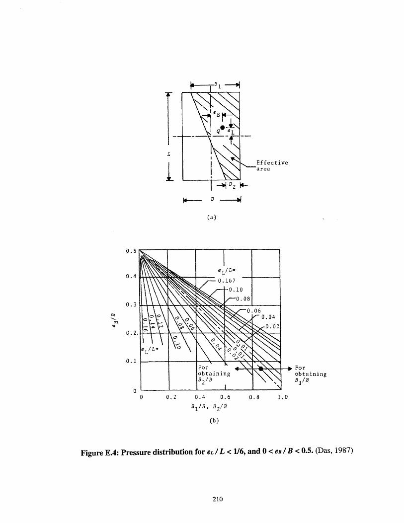
Effective
1 B _
(a)
ForobtainingB 1 /B
0.4 0.6 0.8 1.0
B 1 /B, B 2 /B
(b)
Figure E.4: Pressure distribution for eL /L < 1/6, and 0 < eB/ B < 0.5. (Das, 1987)
210
0.5
0.4
0.3
0. 2.
0.1
00 0.2

Iv
z
IV
Bof
Figure E.5: Determination of maximum pressure. (Peck, Hanson, and Thombum, 1973)
211

212

Appendix F
Precast Segments Cross-Sections
Area: 4.237371 sq mPerimeter: 13.01848 mBounding box: X: -2.85 -- 2.85 m
Y: -0.5944844 -- 0.5855156 mCentroid: X: 0 m
Y: 0 mMoments of inertia: X: 0.4356741 sq m sq m
Y: 7.161368 sq m sq mProduct of inertia: XY: -1.997796e-14 sq m sq mRadii of gyration: X: 0.320651 m
Y: 1.300019 mPrincipal moments(sq m sq m) and X-Y directions about centroid:
1: 0.4356741 about [1 0 ]J: 7.161368 about [0 1 ]
Figure F.l: Expansion segment, cross-section one. (Euro Estudios, 1997)
213
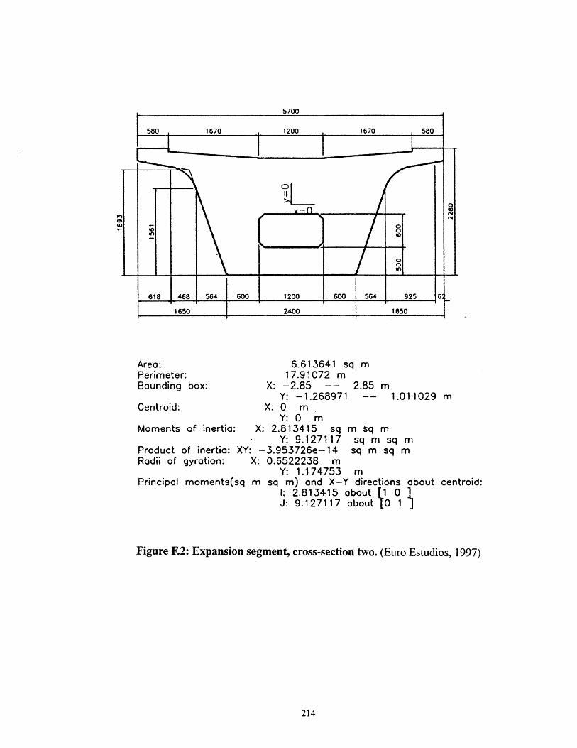
Area:Perimeter:Bounding box:
Centroid:
6.613641 sq m17.91072 m
X: -2.85 -- 2.85 mY: -1.268971 -- 1.011029 m
X: 0 mY: 0 m
Moments of inertia: X: 2.813415 sq m tq mY: 9.127117 sq m sq m
Product of inertia: XY: -3.953726e-14 sq m sq mRadii of gyration: X: 0.6522238 m
Y: 1.174753 mPrincipal moments(sq m sq m) and X-Y directions about centroid:
I: 2.813415 about [1 0J: 9.127117 about 0 1
Figure E2: Expansion segment, cross-section two. (Euro Estudios, 1997)
214

5700
580 , 1670 1200 1670 580
I-rI
0 -
- 0
618
/i7 85d
468
0
00* -
1000
.39.
564 1
Area:Perimeter:Bounding box:
Centroid:
1200 11650 2400 1650
1200 564
6.903641 sq m17.17072 m
X: -2.85 -- 2.85 mY: -1.211559 -- 1.068441 m
X: 0 .mY: 0 m
Moments of inerti6: X: 2.947524 sq m sq mY: 9.175617 sq m sq m
Product of inertia: XY: 5.897599e-15 sq m sq mRadii of gyration: X: 0.6534157 m
Y: 1.152865 mPrincipal moments(sq m sq m) and X-Y directions about centre
1: 2.947524 about [1 0J: 9.175617 about [0 1
Figure F.3: Pier segment. (Euro Estudios, 1997)
215
I I !
.c °
• i_
r . r I . I 1 ..1..
L-l

5700
580 1670 1200 1670 580
o
x=O
618 468 564 247 1907 5 7 293 925 61650 2400 1650
Area: 3.06642 sq m
Perimeter: 22.82792 mBounding box: X: -2.85 -- 2.85 m
Y: -1.378351 -- 0.9016492 mCentroid: X: O. m
Y: 0 mMoments of inertia: X: 1.855144 sq m sq m
Y: 6.886054 sq m sq mProduct of inertia: XY: 8.511437e-14 sq m sq mRadii of gyration: X: 0.777809 m
Y: 1.498544 mPrincipal moments(sq m sq m) and X-Y directions about centroid:
1: 1.855144 about [1 0 1J: 6.886054 about 0 1
Figure F.4: Typical segment. (Euro Estudios, 1997)
216
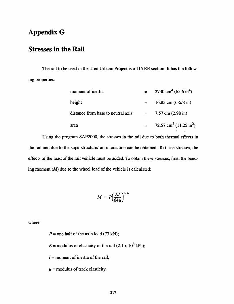
Appendix G
Stresses in the Rail
The rail to be used in the Tren Urbano Project is a 115 RE section. It has the follow-
ing properties:
moment of inertia = 2730 cm4 (65.6 in4)
height = 16.83 cm (6-5/8 in)
distance from base to neutral axis = 7.57 cm (2.98 in)
area = 72.57 cm 2 (11.25 in2)
Using the program SAP2000, the stresses in the rail due to both thermal effects in
the rail and due to the superstructure/rail interaction can be obtained. To these stresses, the
effects of the load of the rail vehicle must be added. To obtain these stresses, first, the bend-
ing moment (M) due to the wheel load of the vehicle is calculated:
M p(EI 1/4
where:
P = one half of the axle load (73 kN);
E = modulus of elasticity of the rail (2.1 x 10⁸ kPa);
I = moment of inertia of the rail;
u = modulus of track elasticity.
217

The value of u was assumed to be 17,238 kPa (2500 psi).
After computing M, the stress due to bending (S) in the rail can be checked with the
equation:
McS
I
where c can be taken as either the distance from the neutral axis to the bottom or to the top
of the rail. These stresses are added to the ones obtained using SAP2000 to compute the
total stress.
218
Bibliography
1. American Association of State Highway and Transportation Officials (AASHTO), Stan-dard Specification for Highway Bridges, Sixteenth Edition, AASHTO, 1996.
2. American Concrete Institute (ACI), Design Handbook Volume 2: Columns, ACI, 1990.
3. American Concrete Institute (ACI), Building Code Requirements for Reinforced Con-crete ACI 318-89) (Revised 1992) and Commentary -- ACI 318R-89 (Revised 1992),ACI, 1992.
4. American Institute of Architects (AIA), Life Cycle Cost Analysis: A Guide for Archi-tects, AIA, 1977.
5. Arditi, David A., and Hany M. Messiha, "Life-Cycle Costing in Municipal ConstructionProjects", Journal of Infrastructure Systems, Volume 2, No. 1, March 1996.
6. Ashby, Michael F., and David R. H. Jones, Engineering Materials 1: An Introduction toTheir Properties & Applications, Second Edition, Butterworth-Heinemann, 1996.
7. Barker, James M., "Construction Techniques for Segmental Concrete Bridges", Journalof the Prestressed Concrete Institute, Volume 25, No. 4, July-August, 1980.
8. Barker, Richard M., and Jay A. Puckett, Design of Highway Bridges, John Wiley &Sons, 1997.
9. Barker, Richard, and Jay A. Puckett, Design of Highway Bridges: Based on AASHTOLRFD, Bridge Design Specifications, John Wiley & Sons, 1997.
10. Bender, Brice F., and H. Hubert Janssen, "Geometry Control of Precast Segmental Con-crete Bridges", Proceedings of the Segmental Concrete Bridge Conference, 1982.
11. Beneda, Robert V., and Phillip A. McKenna, Lessons Learned in 25 Years of Engineer-ing MARTA's Aerial Structures, MARTA, 1997.
12. Bowles, Joseph E., Foundation Analysis and Design, Fifth Edition, McGraw-Hill, 1996.
13. Burke, Martin P., "Flawed Assumptions and the Failure of Bridge Deck Joints and Bear-ings", The Fourth World Congress on Joint Sealing and Bearing Systems for ConcreteStructures, ACI, 1996.
14. Casey, C. J., "Zilwaukee Bridge Construction", Proceedings of the Segmental ConcreteBridge Conference, 1982.
219

15. Cernica, John N., Geotechnical Engineering: Foundation Design, John Wiley & Sons,1995.
16. Chabert, A., and R. Ambrosino, "Behavior of Expansion Joints", The Fourth WorldCongress on Joint Sealing and Bearing Systems for Concrete Structures, ACI, 1996.
17. Cohen, E., "In the Eye of the Beholder", Esthetics in Concrete Bridge Design, ACI,1990.
18. Computer and Structures, Inc. (CSI), SAP2000: Integrated Finite Element Analysis andDesign of Structures -- Analysis Reference, Volume 1, CSI, 1997.
19. Computer and Structures, Inc. (CSI), SAP2000: Integrated Finite Element Analysis andDesign of Structures -- Analysis Reference, Volume 2, CSI, 1997.
20. Computer and Structures, Inc. (CSI), SAP2000: Integrated Finite Element Analysis andDesign of Structures -- Getting Started, Volume 2, CSI, 1997.
21. Concrete Reinforcing Steel Institute (CRSI), CRSI Handbook, CRSI, 1982.
22. Cowan, Henry J. and Peter R. Smith, The Design of Prestressed Concrete, Angus &Robertson, 1966.
23. Curtin, W. G., G. Shaw, G. I. Parkinson, and J. M. Golding, Structural FoundationDesigners Manual, Blackwell Scientific Publications, 1994.
24. Dale, S. J., "Introduction to Life Cycle Costing", Life Cycle Costing for Construction,Chapman & Hall, 1993.
25. Das, Braja M., Theoretical Foundation Engineering, Elsevier, 1987.
26. De Brito, J., and F. A. Branco, "Bridge Management Policy Using Cost Analysis", Pro-ceedings of the Institution of Civil Engineers: Structures and Buildings, No. 104,November 1994.
27. Degenkolb, Oris H., Concrete Box Girder Bridges, ACI, 1977.
28. Euro Estudios, Model of Structure (Pier 1 - Pier 7). Foundation with Piles, Review ofStresses In Superstructure, 95% Submittal, Calculation No. 96040-3.1a, ASC 1, Con-tract No.AC-500007, August 8, 1997.
29. Euro Estudios, Model of Structure (Pier 24 - Pier 30), Review of Stresses In Superstruc-ture, 95% Submittal, Calculation No. 96040-5.2, ASC 1, Contract No. AC-500007, Sep-tember, 1997.
220

30. Fryba, Ladislav, Dynamics of Railway Bridges, Thomas Telford, 1996.
31. Gloyd, C. S., "Some Thoughts on Bridge Esthetics", Esthetics in Concrete BridgeDesign, ACI, 1990.
32. Gottemoeller, F., "Esthetics and Engineers", Esthetics in Concrete Bridge Design, ACI,1990.
33. Gottemoeller, Frederick, "Aesthetics and Engineers: Providing for Aesthetic Quality inBridge Design", Bridge Aesthetics Around the World, Transportation Research Board,1991.
34. Grant, A., "Beauty and Bridges", Esthetics in Concrete Bridge Design, ACI, 1990.
35. Haviland, David S., Life Cycle Cost Analysis 2: Using It in Practice, The AmericanInstitute of Architects, 1978.
36. Hay, William W., Railroad Engineering, Second Edition, John Wiley & Sons, 1982.
37. Kawashima, K., "Bridges", Computer Analysis and Design of Earthquake ResistantStructures -- A Handbook, Computational Mechanics Publications, 1997.
38. K6ster, Waldemar, Expansion Joints in Bridges and Concrete Roads, MacLaren andSons, 1969.
39. Kruckemeyer, K. E., "Bridge Design Process -- Achieving the Goal of Aesthetic Qual-ity",Esthetics in Concrete Bridge Design, ACI, 1990.
40. Lacroix, R., "Fundamental Principles of Bridge Esthetics", Esthetics in Concrete BridgeDesign, ACI, 1990.
41. Lee, David J., Bridge Bearings and Expansion Joints, Second Edition, E & F. N. Spon,1994.
42. Leonhardt, Fritz, Prestressed Concrete: Design and Construction, Wilhelm Ernst &Sons, 1964.
43. Leonhardt, Fritz, Bridges: Aesthetics and Design, M.I.T. Press, 1982.
44. Libby, James R., Modern Prestressed Concrete: Design Principle and ConstructionMethods, Van Nostrand Reinhold, 1971.
45. Liebenberg, A. C., "The Controversy About Rules for the Aesthetic Design of Bridge,Esthetics in Concrete Bridge Design, ACI, 1990.
221
46. Liebenberg, A. C., "Aesthetic Evaluation of Bridges", Bridge Aesthetics Around theWorld, Transportation Research Board, 1991.
47. Lin, T. Y., and Ned H. Bums, Design of Prestressed Concrete Structures, Third Edition,John Wiley & Sons, 1981.
48. Long, J. E., Bearings in Structural Engineering, Butterworth & Co., 1974.
49. Mays, R. R., "Aesthetic Rules Should Not Be Set in Concrete -- A Bridge Architect'sView on Bridge Design", Bridge Aesthetics Around the World, Transportation ResearchBoard, 1991.
50. Menn, Christian, Prestressed Concrete Bridges, Birkhiuser Verlag, 1990.
51. Menn, Christian, "Aesthetics in Bridge Design", Bridge Aesthetics Around the World,Transportation Research Board, 1991.
52. Miller, Maurice D., "Durability Survey of Segmental Concrete Bridges", PCI Journal,May-June, 1995.
53. Muller, Jean M., "Aesthetics in Concrete Segmental Bridges", Bridge AestheticsAround the World, Transportation Research Board, 1991.
54. Muller, J., "Precast Segmental Construction", Continuous and Integral Bridges, E & FNSpon, 1994.
55. Muller, J. M., and L. F. McCallister, "Esthetics for Concrete Segmental Bridges",Esthetics in Concrete Bridge Design, ACI, 1990.
56. Naaman, Antoine E., Prestressed Concrete Analysis and Design: Fundamentals,McGraw-Hill, 1982.
57. Narbey, Khachaturian, and German Gurfinkel, Prestressed Concrete, McGraw-Hill,1969.
58. Nawy, Edward G., Prestressed Concrete: A Fundamental Approach, Prentice Hall,1989.
59. Nilson, Arthur H., Design of Prestressed Concrete, Second Edition, John Wiley & Sons,1987.
60. Nilson, Arthur H. and George Winter, Design of Concrete Structures, Eleventh Edition,McGraw-Hill, 1991.
61. Otter, J., "Ontario Segmental Bridges: A Contractor's Viewpoint", Proceedings of theSegmental Concrete Bridge Conference, 1982.
222
62. Pais, Artur, and Eduardo Kausel, "Approximate Formulas for Dynamic Stiffnesses ofRigid Foundations", Soil Dynamics and Earthquake Engineering, Volume 7, No. 4,1988.
63. Parsons, Robert R., and Graham W. Taylor, "Vancouver ALRT Special Guideway Struc-ture", 12th Congress, International Association for Bridge and Structural Engineering,1984.
64. Pats, Monica L., "Introduction", Aesthetic Bridges Users' Guide, Maryland Departmentof Transportation, 1993.
65. Peck, Ralph B., Walter E. Hanson, and Thomas H. Thornburn, Foundation Engineering,Second Edition, John Wiley & Sons, 1973.
66. Podolny, Walter and Jean M. Muller, Construction and Design of Prestressed ConcreteSegmental Bridges, John Wiley & Sons, 1982.
67. Post-Tensioning Institute and Prestressed Concrete Institute, Precast Segmental BoxGirder Bridge Manual, PTI & PCI, 1978
68. Precast/Prestressed Concrete Institute, PCI Design Handbook: Precast and PrestressedConcrete, Fourth Edition, PCI, 1992.
69. Profillidis, V. A., Railway Engineering, Avebury Technical, 1995.
70. Prommersberger, Gerhard, and Richard Rojek, "Transmission of Longitudinal Forceson Railroad Bridges", 12th Congress, International Association for Bridge and Struc-tural Engineering, 1984.
71. Revelo, Carlos King, "Form, Modeling, and Composition in Bridge Aesthetics", BridgeAesthetics Around the World, Transportation Research Board, 1991.
72. Ritner, J. C., "Creating a Beautiful Concrete Bridge", Esthetics in Concrete BridgeDesign, ACI, 1990.
73. Sweet's Group, Sweet's Engineering & Retrofit: Mechanical, Electrical, Civil/StructuralCatalog File, Vol. 2, McGraw-Hill, 1992.
74. Taly, Narendra, Design of Modem Highway Bridges, McGraw-Hill, 1998.
75. Tilly, G. P., "Historical Review of the Development of Continuity and Expansion Jointsin Bridges", Continuous and Integral Bridges, E & FN Spon, 1994.
76. Tonias, Demetrios E., Bridge Engineering, McGraw-Hill, 1995.
223

77. Tren Urbano, and GMAEC, Bayam6n Contract Category I Contract Drawings, January2, 1996.
78. Tren Urbano, and GMAEC, Bayam6n Contract Category II Contract Drawings, January2, 1996.
79. Tren Urbano, and GMAEC, Tren Urbano Fixed Facilities Category I Contract Draw-ings, May 31, 1996.
80. Tren Urbano, and GMAEC, Tren Urbano Fixed Facilities Category II Contract Draw-ings, May 31, 1996.
81. Troitsky, M. S., Planning and Design of Bridges, John Wiley & Sons, 1994.
82. United States Department of Transportation, Federal Transit Administration, Govern-ment of Puerto Rico, Department of Transportation and Public Works of Puerto Rico,and Highway and Transportation Authority of Puerto Rico, Phase I of Tren Urbano:Systems and Test Track Turnkey Contract -- Design Criteria Part A, Contract Book III,Contract No. 500006 STTT, June 26, 1996.
83. Wang, Chu-Kia, and Charles G. Salmon, Reinforced Concrete Design, Fifth Edition,Harper Collins, 1992,
84. Wasserman, Edward P., "Aesthetics for Short- and Medium-Span Bridges", Bridge Aes-thetics Around the World, Transportation Research Board, 1991.
85. Watson, Stewart C., "A Half-Century of Involvement with Joints and Bearings andSome Lessons Learned", The Fourth World Congress on Joint Sealing and Bearing Sys-tems for Concrete Structures, ACI, 1996.
86. Watson, Stewart C., "The Role of Joints and Bearings in the Esthetic Discipline ofStructures", The Fourth World Congress on Joint Sealing and Bearing Systems for Con-crete Structures, ACI, 1996.
87. White, Kenneth R., John Minor, and Kenneth N. Derucher, Bridge Maintenance Inspec-tion and Evaluation, Second Edition, Marcel Dekker, 1992.
88. Wium, Daniel J. W. and Oral Buyukozturk, Behavior of Precast Segmental ConcreteBridges, M.I.T. Research Report No. R84-06, May 1984.
89. Wium, Daniel J. W. and Oral Buyukozturk, "Variability in Long-Term Concrete Defor-mations", Journal of Structural Engineering, Vol. 111, No. 8, August, 1985.
90. Wolf, John P., Foundation Vibration Analysis Using Simple Physical Models, PrenticeHall, 1994.
224

91. Xanthakos, Petros P., Theory and Design of Bridges, John Wiley & Sons, 1994.
92. Xanthakos, Petros P., Bridge Substructure and Foundation Design, Prentice Hall, 1995.
225