assessment of dam safety coal combustion surface ... · cha project no. 20085.1010.1510 assessment...
TRANSCRIPT


American Electric Power
Muskingum River Power Plant
Waterford, Ohio
Prepared for
Lockheed Martin 2890 Woodridge Ave #209 Edison, New Jersey 08837
December 22, 2009
CHA Project No. 20085.1010.1510
Assessment of Dam Safety Coal Combustion Surface Impoundments (Task 3)
Draft Report

-ii- Draft Report Assessment of Dam Safety of
Coal Combustion Surface Impoundments American Electric Power
Muskingum River Power Plant Beverley, OH
I acknowledge that the management units referenced herein:
Upper Fly Ash Reservoir Dams Middle Fly Ash Reservoir Dams Lower Fly Ash Reservoir Dam Units 1-4 Bottom Ash Pond Dam
Have been assessed on October 21, 2009 and October 22, 2009 Signature: _________________________________________ Malcolm D. Hargraves, P.E. Senior Geotechnical Engineer Registered in the State of Ohio Reviewer: _________________________________________ Warren A. Harris, P.E. Geotechnical Operations Manager
-iii- Draft Report Assessment of Dam Safety of
Coal Combustion Surface Impoundments American Electric Power
Muskingum River Power Plant Beverley, OH
TABLE OF CONTENTS SECTION PAGE NUMBER 1.0 INTRODUCTION & PROJECT DESCRIPTION........................................................ 1
1.1 Introduction............................................................................................................. 1 1.2 Project Background................................................................................................. 2
1.2.1 State Issued Permits ................................................................................................ 3 1.2.1.1 NPDES Permits........................................................................................ 3 1.2.1.2 Ohio Department of Natural Resources Dam Permit .............................. 4
1.3 Site Description....................................................................................................... 4 1.3.1 Upper Fly Ash Reservoir ........................................................................................ 5
1.3.1.1 Mill Stone Creek Dam ............................................................................. 5 1.3.1.2 No-Name Creek Dam .............................................................................. 6 1.3.1.3 Wing Dike................................................................................................ 6 1.3.1.4 Spillway Dam........................................................................................... 7 1.3.1.5 Freeboard Dam......................................................................................... 7
1.3.2 Middle Fly Ash Reservoir....................................................................................... 8 1.3.3 Lower Fly Ash Reservoir........................................................................................ 9 1.3.4 Units 1-4 Bottom Ash Pond.................................................................................. 10 1.3.5 Other Impoundments ............................................................................................ 11
1.4 Previously Identified Safety Issues....................................................................... 11 1.4.1 Previously Identified Safety Issues - Upper Fly Reservoir................................... 11 1.4.2 Previously Identified Safety Issues - Middle Fly Reservoir ................................. 12 1.4.3 Previously Identified Safety Issues - Lower Fly Ash Reservoir........................... 12 1.4.4 Previously Identified Safety Issues - Units 1-4 Bottom Ash Pond....................... 12
1.5 Site Geology.......................................................................................................... 13 1.6 Bibliography ......................................................................................................... 14
2.0 FIELD ASSESSMENT................................................................................................... 19
2.1 Visual Observations .............................................................................................. 19 2.2 Visual Observation – Upper Fly Ash Reservoir ................................................... 20
2.2.1 Mill Stone Creek Dam .......................................................................................... 20 2.2.2 No-Name Creek Dam ........................................................................................... 22 2.2.3 Wing Dam............................................................................................................. 23 2.2.4 Spillway Dam........................................................................................................ 25 2.2.5 Freeboard Dam...................................................................................................... 26 2.2.6 Upper Fly Ash Reservoir – Outlet Structure......................................................... 27
2.3 Visual Observations – Middle Fly Ash Reservoir ................................................ 27 2.3.1 Middle Fly Ash Reservoir Dam............................................................................ 27 2.3.2 Emergency Spillway Dam .................................................................................... 29 2.3.3 Middle Fly Ash Dam – Outlet Structure............................................................... 30
2.3.3.1 Middle Fly Ash Dam Emergency Spillway........................................... 30 2.4 Visual Observations – Lower Fly Ash Reservoir ................................................. 30
2.4.1 Lower Fly Ash Reservoir Dam............................................................................. 30
-iv- Draft Report Assessment of Dam Safety of
Coal Combustion Surface Impoundments American Electric Power
Muskingum River Power Plant Beverley, OH
TABLE OF CONTENTS - continued SECTION PAGE NUMBER
2.4.2 Lower Fly Ash Reservoir - Outlet Structure......................................................... 32
2.5 Visual Observations – Units 1-4 Bottom Ash Pond ............................................. 32 2.5.1 Units 1-4 Bottom Ash Pond.................................................................................. 33 2.5.2 Units 1-4 Bottom Ash Pond – Outlet Structure .................................................... 35
2.6 Monitoring Instrumentation .................................................................................. 35 2.6.1 Pond and Reservoir Water Levels......................................................................... 35 2.6.2 Monitoring Instrumentation – Upper Fly Ash Reservoir...................................... 36
2.6.2.1 Upper Fly Ash Reservoir Piezometers...................................................... 36 2.6.2.2 Upper Fly Ash Reservoir Survey Monuments.......................................... 37 2.6.2.3 Upper Fly Ash Reservoir Inclinometers ................................................... 39
2.6.3 Monitoring Instrumentation – Middle Fly Ash Reservoir .................................... 40 2.6.4 Monitoring Instrumentation – Lower Fly Ash Reservoir ..................................... 40 2.6.5 Monitoring Instrumentation – Units 1-4 Bottom Ash Pond ................................. 41
3.0 DATA EVALUATION ................................................................................................... 99
3.1 Design Assumptions ............................................................................................. 99 3.2 Hydrologic and Hydraulic Design ........................................................................ 99
3.2.1 Hydrologic and Hydraulic Design – Ash Pond Complex..................................... 99 3.2.2 Hydrologic and Hydraulic Design – Units 1-4 Bottom Ash Pond...................... 100
3.3 Structural Adequacy & Stability......................................................................... 101 3.3.1 Subsurface Investigation and Soil Testing Program........................................... 102 3.3.2 Stability - Upper Fly Ash Reservoir Dams and Dikes........................................ 105
3.3.2.1 Case I – End of Construction............................................................... 105 3.3.2.2 Cases II and III – Sudden Drawdown.................................................. 106 3.3.2.3 Case IV – Partial Pool.......................................................................... 106 3.3.2.4 Case V – Steady Seepage with Maximum Storage Pool ..................... 106 3.3.2.5 Case VI – Steady Seepage with Surcharge Pool.................................. 107 3.3.2.6 Case VII – Earthquake Loading Condition.......................................... 107
3.3.2 Stability - Middle Fly Ash Reservoir Dam......................................................... 108 3.3.3 Stability – Lower Fly Ash Reservoir .................................................................. 110 3.3.4 Stability – Units 1-4 Bottom Ash Pond .............................................................. 111
3.4 Foundation Conditions........................................................................................ 114 3.4.1 Documentation of Foundation Preparations ....................................................... 114
3.5 Operations & Maintenance ................................................................................. 114 3.5.1 Owner Inspections .............................................................................................. 114
3.5.2 State of Ohio Inspections .................................................................................... 117 4.0 CONCLUSIONS/RECOMMENDATIONS ............................................................... 135
4.1 Acknowledgement of Management Unit Condition ........................................... 135 4.1.1 Acknowledgement of the Upper Fly Ash Reservoir Dams Conditions.............. 135

-v- Draft Report Assessment of Dam Safety of
Coal Combustion Surface Impoundments American Electric Power
Muskingum River Power Plant Beverley, OH
TABLE OF CONTENTS - continued SECTION PAGE NUMBER
4.1.2 Acknowledgement of the Middle & Lower Fly Ash Reservoir Dams ............... 135 4.1.2 Acknowledgement of the Units 1-4 Bottom Ash Pond Dike Conditions ........... 135
4.2 Monitoring of Seeps............................................................................................ 136 4.3 Repair of Erosion ................................................................................................ 137 4.4 Repair of Rodent Burrows .................................................................................. 138 4.5 Additional Stability Analyses – Upper Fly Ash Reservoir................................. 138 4.6 Additional Stability Analyses – Middle Fly Ash Reservoir ............................... 139 4.7 Additional Stability Analyses – Lower Fly Ash Reservoir ................................ 139 4.8 Stability of the Units 1-4 Bottom Ash Pond East Dike ...................................... 139 4.9 Trees and Stumps................................................................................................ 140 4.10 Establishing Vegetation ...................................................................................... 141 4.11 Monitoring of Middle Fly Ash Reservoir Principal Spillway ............................ 141 4.12 Repair of Damaged Instrumentation................................................................... 141 4.13 Routine Observations, Data Collection and Documentation .............................. 142
5.0 CLOSING ...................................................................................................................... 143
TABLES
Table 1 - Ash Pond NPDES Discharge Locations.......................................................................... 4 Table 2 – Approximate Precipitation Prior to Site Visit............................................................... 19 Table 3 – Pond and Reservoir Water Levels - December 2001 to 2008....................................... 36 Table 4 – Summary of Settlement Monument Deformation Data for Years 1975-2008.............. 37 Table 5 – Summary of Units 1-4 Bottom Ash Pond Flood Modeling........................................ 101 Table 6 - Minimum Safety Factors Required ............................................................................. 102 Table 7 – Shear Strength and Density Parameters for Proposed Borrow Materials................... 103 Table 8 – Shear Strength and Density Parameters...................................................................... 103 Table 9 – Shear Strength and Density Parameters for the Wing Dam Materials ....................... 104 Table 10 – Shear Strength and Density Parameters for the Freeboard Dams Materials............. 104 Table 11 – Factors of Safety for End of Construction ................................................................ 106 Table 12 – Factors of Safety for Steady Seepage with Maximum Storage Pool........................ 107 Table 13 – Factors of Safety for Steady Seepage with Surcharge Pool...................................... 107 Table 14 – Estimated Total Displacement at the Maximum Section of the Dams and Dikes.... 108 Table 15 – Strength Values for Static Conditions ...................................................................... 112 Table 16 – Strength Values for Pseudo- Static Conditions......................................................... 112 Table 17 – Stability Analysis Summary – Existing Conditions ................................................. 113 Table 18 – Summary of 2009 Annual Inspection Conclusions & Recommendations ............... 114 Table 19 – Summary of Required Remedial Measures .............................................................. 118
-vi- Draft Report Assessment of Dam Safety of
Coal Combustion Surface Impoundments American Electric Power
Muskingum River Power Plant Beverley, OH
FIGURES
Figure 1 - Project Location Map ................................................................................................. 16 Figure 2 - Photo Site Plan ........................................................................................................... 17 Figure 3 - Critical Infrastructure Map........................................................................................... 18 Figure 4A - Photo Location Plan ................................................................................................. 42 Figure 4B - Photo Location Plan ................................................................................................. 43 Figure 4C - Photo Location Plan ................................................................................................. 44 Figure 4D - Photo Location Plan ................................................................................................. 45 Figure 4E - Photo Location Plan .................................................................................................. 46 Figure 4F - Photo Location Plan .................................................................................................. 47 Figure 4G - Photo Location Plan ................................................................................................. 48 Figure 4H - Photo Location Plan ................................................................................................. 49 Figure 5A - Historical Records of Water Levels at the Upper Reservoir Since 2004 ................. 94 Figure 5B - Water Levels in Piezometers at the Main Dam Since 2004 ..................................... 95 Figure 6 - Historical Records of Water Levels at the Middle Reservoir Since 1987 .................. 96 Figure 7 - Historical Records of Water Levels at the Low Reservoir Since 1991 ....................... 97 Figure 8 - Historical Records of Water Levels at the Units 1-4 Bottom Ash Pond ..................... 98 Figure 9A - Middle Reservoir Dam Stability Analysis ...............................................................120 Figure 9B - Middle Reservoir Dam Stability Analysis ...............................................................121 Figure 9C - Middle Reservoir Dam Stability Analysis ...............................................................122 Figure 10A - Lower Reservoir Dam Stability Analysis...............................................................123 Figure 10B - Lower Reservoir Dam Stability Analysis .............................................................124 Figure 10C - Lower Reservoir Dam Stability Analysis ...............................................................125 Figure 10D - Lower Reservoir Dam Stability Analysis .............................................................126 Figure 11A - Units 1-4 Bottom Ash Pond Stability Analysis .....................................................127 Figure 11B - Units 1-4 Bottom Ash Pond Stability Analysis ....................................................128 Figure 11C - Units 1-4 Bottom Ash Pond Stability Analysis ....................................................129 Figure 11D - Units 1-4 Bottom Ash Pond Stability Analysis ....................................................130 Figure 11E - Units 1-4 Bottom Ash Pond Stability Analysis ....................................................131 Figure 11F - Units 1-4 Bottom Ash Pond Stability Analysis ....................................................132 Figure 11G - Units 1-4 Bottom Ash Pond Stability Analysis ....................................................133 Figure 11H - Units 1-4 Bottom Ash Pond Stability Analysis ....................................................134
APPENDIX
Appendix A - Completed EPA Coal Combustion Dam Inspection Checklist Form & Completed EPA Coal Combustion Waste (CCW) Impoundment Inspection Form

-1- Draft Report Assessment of Dam Safety of
Coal Combustion Surface Impoundments American Electric Power
Muskingum River Power Plant Beverley, OH
1.0 INTRODUCTION & PROJECT DESCRIPTION
1.1 Introduction
CHA was contracted by Lockheed Martin (a contractor to the United States Environmental
Protection Agency) to perform site assessments of selected coal combustion surface
impoundments (Project #0-381 Coal Combustion Surface Impoundments/Dam Safety
Inspections). As part of this contract, CHA was assigned to perform a site assessment of the Ash
Reservoir Complex and the Units 1-4 Bottom Ash Pond.
CHA made a site visit to the Muskingum River Power Plant on October 21, 2009 and October
22, 2009 to inventory coal combustion surface impoundments at the facility, perform visual
observations of the containment dams and dikes, and collect relevant information.
CHA Engineers Malcolm Hargraves, P.E. and Rebecca Filkins were accompanied by the
following individuals:
Company or Organization Name
American Power Company Pedro Amaya, P.E., Senior Engineer
American Power Company Behrad Zand, P.E., Ph.D., Engineer II
American Power Company Jim Ludwig, Plant Environmental Coordinator Sr.
American Power Company Russel Gwin, Maintenance Superintendent
American Power Company David Wickline, Plant Manager
American Power Company Jeffrey Wiegand, Energy Production Superintendent
American Power Company Deanna King, Environmental Specialist IV
ODNR – Division of Water Mia Kannuck, P.E., Project Engineer
ODNR – Division of Water Tom G. Lagucke, Construction Specialist
-2- Draft Report Assessment of Dam Safety of
Coal Combustion Surface Impoundments American Electric Power
Muskingum River Power Plant Beverley, OH
1.2 Project Background
The Muskingum River Power Plant is owned by Ohio Power Company, a subsidiary of
American Electric Power (AEP). The facility is located in Waterford, OH in Washington County
on the west bank of the Muskingum River, as shown in Figure 1 – Project Location Map. The
Township Road 607 Bridge over the Muskingum River is immediately adjacent to the facility,
just north of the coal stacking area. The site is accessible by State Highway 60, County Road 32
and Township Road 105.
The Ash Reservoir Complex consists of three separate impoundments; the Upper Fly Ash
Reservoir, the Middle Fly Ash Reservoir and the Lower Fly Ash Reservoir. The Upper Fly Ash
Reservoir was created by constructing five separate dams and dikes; the Mill Stone Creek, No-
Name Creek, the Wing (Main and Extension), the Spillway, and the Freeboard Dams. The
Middle Fly Ash Reservoir is impounded by the Middle Reservoir Dam and the Emergency
Spillway Dam (aka Saddle Dam). The Lower Fly Ash Reservoir is impounded by the Lower
Reservoir Dam. Figure 2 – Photo Site Plan shows the location of the reservoirs and their
associated dikes and dams.
The Units 1-4 Bottom Ash Pond is located north of County Road 32, adjacent to the Muskingum
River. The pond consists of a northern portion filled with dry dredge spoils, a southern main
pond for the storage of bottom ash, and a connecting channel between the two areas. Figure 2 –
Photo Site Plan shows the locations of the Units 1-4 Bottom Ash Pond and its corresponding
dikes.
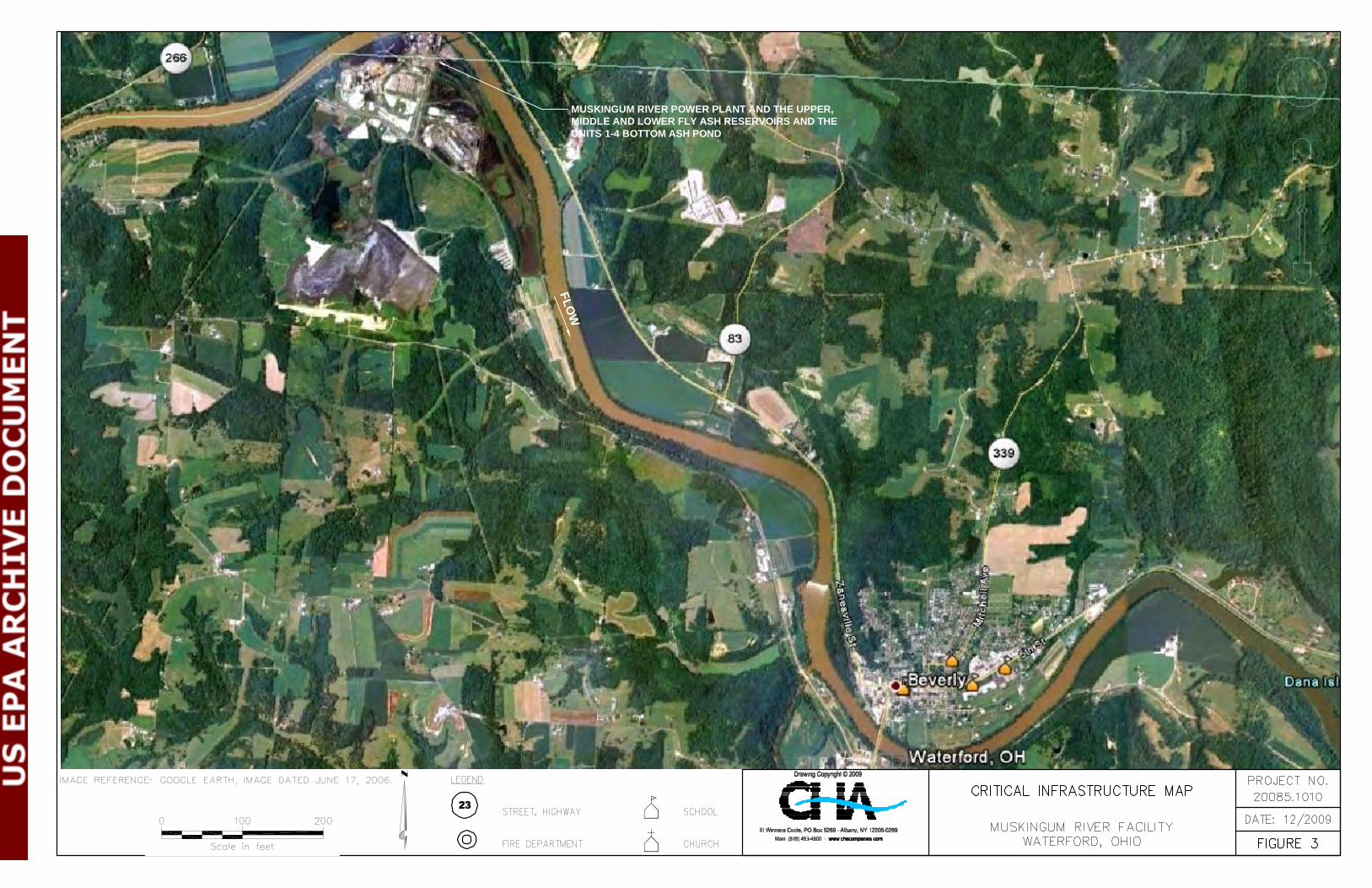
An aerial photograph of the region indicating the location of the Muskingum River Power Plant
and identifying schools, hospitals, or other critical infrastructure located within approximately
five miles down gradient of the ash ponds is provided as Figure 3 – Critical Infrastructure Map.

-3- Draft Report Assessment of Dam Safety of
Coal Combustion Surface Impoundments American Electric Power
Muskingum River Power Plant Beverley, OH
The ash management impoundments at the Muskingum River Power Plant are under the
jurisdiction of the Ohio Department of Natural Resources (ODNR) Division of Water – Dam
Safety Program. The structures creating the impoundments for the Upper, Middle and Lower Fly
Ash Reservoirs are classified by ODNR as Class I dams based upon the height, storage capacity
and potential downstream hazard of each of the dams. Potential downstream hazards, considered
by the ODNR in their November 3, 2008 Dam Safety Inspection Reports, included the probable
loss of human life, loss of public water supply and the potential damage to public utilities and
damage to local roads.
The impoundment for the Units 1-4 Bottom Ash Pond has been given a Class II Hazard rating by
the State of Ohio Department of Natural Resources due to the potential for release of materials
into the Muskingum River.
The Upper, Middle and Lower Fly Ash Reservoirs dikes and dams have been given a “High”
hazard rating and the Units 1-4 Bottom Ash Pond has been given a “Significant” hazard rating as
defined on the EPA Coal Combustion Dam Inspection Checklists and Coal Combustion Waste
(CCW) Impoundment Inspection Forms, included Appendix A.
1.2.1 State Issued Permits
The Ohio Power Company has received the following state and federal issued permits for the
facility based upon publicly available records:
1.2.1.1 NPDES Permits
Application No. OH0006149 and Permit No. 0IB00003*OD has been issued to the Ohio Power
Company (c/o American Electric Power Muskingum River Plant) authorizing discharge under
the National Pollutant Discharge Elimination System (NPDES) to the Mill Stone Creek and
Muskingum River in accordance with effluent limitations, monitoring requirements and other
conditions set forth in the permit. The permit became effective on August 1, 2007 and will
expire on July 31, 2011. The permit covers the entire generating facility including 11 discrete
-4- Draft Report Assessment of Dam Safety of
Coal Combustion Surface Impoundments American Electric Power
Muskingum River Power Plant Beverley, OH
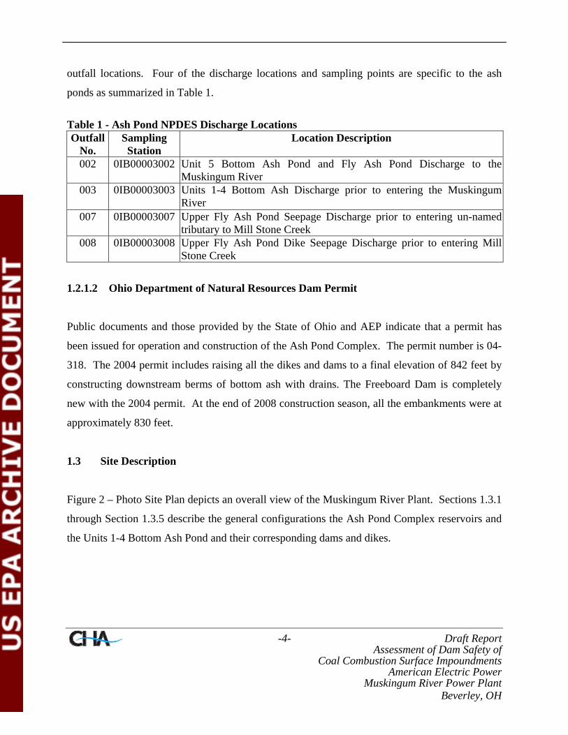
outfall locations. Four of the discharge locations and sampling points are specific to the ash
ponds as summarized in Table 1.
Table 1 - Ash Pond NPDES Discharge Locations Outfall
No. Sampling Station
Location Description
002 0IB00003002 Unit 5 Bottom Ash Pond and Fly Ash Pond Discharge to the Muskingum River
003 0IB00003003 Units 1-4 Bottom Ash Discharge prior to entering the Muskingum River
007 0IB00003007 Upper Fly Ash Pond Seepage Discharge prior to entering un-named tributary to Mill Stone Creek
008 0IB00003008 Upper Fly Ash Pond Dike Seepage Discharge prior to entering MillStone Creek
1.2.1.2 Ohio Department of Natural Resources Dam Permit
Public documents and those provided by the State of Ohio and AEP indicate that a permit has
been issued for operation and construction of the Ash Pond Complex. The permit number is 04-
318. The 2004 permit includes raising all the dikes and dams to a final elevation of 842 feet by
constructing downstream berms of bottom ash with drains. The Freeboard Dam is completely
new with the 2004 permit. At the end of 2008 construction season, all the embankments were at
approximately 830 feet.
1.3 Site Description
Figure 2 – Photo Site Plan depicts an overall view of the Muskingum River Plant. Sections 1.3.1
through Section 1.3.5 describe the general configurations the Ash Pond Complex reservoirs and
the Units 1-4 Bottom Ash Pond and their corresponding dams and dikes.

-5- Draft Report Assessment of Dam Safety of
Coal Combustion Surface Impoundments American Electric Power
Muskingum River Power Plant Beverley, OH
1.3.1 Upper Fly Ash Reservoir
The Upper Reservoir Dam (ODNR File No. 9415-009) was formed by the construction of a dam,
a wing dike east of the dam and three low freeboard dikes around the reservoir; known as the
Mill Stone Creek Dam, the No-Name Creek Dam, the Wing Dam (Main and Extension), the
Spillway Dam and the Freeboard Dam. The Mill Stone Creek Dam, the No-Name Creek Dam
and the right part of the Wing Dam are collectively referred to as the Main Dam in some design
and inspection reports prepared for the facility.
The Upper Reservoir dams and dikes are currently being raised to increase the available storage
volume. The dams and dikes will be raised to a settled crest of Elev. 842 feet and the reservoir
will have a maximum normal water pool of Elev. 837 feet. The anticipated completion date for
this work is 2011.
The outlet structure for the Upper Reservoir consists of a drop-inlet decanting structure located
in a saddle dam to the west of the wing dike. This spillway is a 24-inch concrete pipe with a 48-
inch square concrete riser with an inlet elevation of 820 feet. The ODNR Dam Inventory Sheet
notes that there is no lake drain or emergency spillway for the Upper Reservoir.
1.3.1.1 Mill Stone Creek Dam
The Mill Stone Creek Dam was constructed to a final settled crest Elev. of 825 feet for a total
maximum height of 140 feet above the stripped ground surface of No-Name Creek and
approximately 100 feet above Mill Stone Creek.
The existing cross section of the Mill Stone Creek Dam consists of an upstream shell of boiler
slag, a central core of impervious silty clay, a downstream transition zone of bottom ash, and a
downstream shell of boiler slag. An impervious backfilled core trench was reportedly excavated
into rock for the full length of the main dam embankment. The crest of the dam is approximately

-6- Draft Report Assessment of Dam Safety of
Coal Combustion Surface Impoundments American Electric Power
Muskingum River Power Plant Beverley, OH
30 feet wide. The upstream embankment slopes are 2H:1V from Elev. 750 feet to the crest and
3H:1V below Elev. 750 feet. The downstream embankment slopes, protected by approximately
18 inches of rip rap, are 2.5H:1V.
On-going construction for the raising of the Upper Reservoir dams and dikes will increase the
Mill Stone Creek Dam to Elev. 842 feet. The new embankment height will consist of an
impervious core on the upstream slope of the dam graded to a 3H:1V and having a width ranging
from 15 to 25 feet. The downstream shell will be comprised of granular fill made of bottom ash
and boiler slag graded to a slope of 2H:1V extending from the base to the crest with a bench at
Elev. 800 feet. A 40-foot wide crest width will be maintained.
1.3.1.2 No-Name Creek Dam
The No-Name Creek Dam is located in the next saddle to the west of Mill Stone Creek Dam. It
is on the same horizontal axis and maintains the crest between Elev. 826 and 830 feet. A
seepage collection pond is located downstream of the toe of the embankment. A small
embankment located on the downstream side of the pond. The toe drains for the dam outlet into
the pond and the pond also collects surface runoff.
Construction for the increase dam height for No-Name Creek Dam has followed the plan
described above for Mill Stone Creek Dam.
1.3.1.3 Wing Dike
The Wing Dike is a 1,500-foot long dike, with a maximum height of 30 feet that was constructed
from the west abutment of the Mill Stone Creek Dam to a low ridge to effect reservoir closure.
The Wing Dike cross section geometry is similar to that of the Mill Stone Creek Dam, with the
exception that a 5-foot deep cut-off trench was provided instead of a core trench.

-7- Draft Report Assessment of Dam Safety of
Coal Combustion Surface Impoundments American Electric Power
Muskingum River Power Plant Beverley, OH
The Wing Dam is divided into two sections separated by a natural ridge. The east side of the
Wing Dam is located in line with the Mill Stone Creek and No-Name Creek Dams. The main
portion of the Wing Dam is located on the west side of the ridge and along the north edge of the
Upper Reservoir impoundment. The toe of the embankment is located within the Middle
Reservoir impoundment.
As previously noted all embankments within the Upper Fly Reservoir are being raised to
Elevation 842 feet. Upstream slopes will be graded at 3H:1V and downstream slopes will be
graded at 2H:1V. The design report indicates that the new embankment will consist of a clay
upstream core and a bottom ash downstream shell. A 20 foot wide bench will be constructed at
Elevation 810 feet. Slope protection will consist of topsoil and seeding for the upstream slope
and riprap on the downstream slope.
1.3.1.4 Spillway Dam
The Spillway Dam is located on the north side of the Upper Fly Ash Reservoir and the toe of the
embankment terminates in the Middle Reservoir. It is immediately east of the Wing Dam. The
maximum dam height is between 25 and 30 feet. There is a concrete outfall structure located
upstream of the embankment that outlets into the Middle Fly Ash Reservoir.
The current freeboard dike will be raised to Elevation 842 feet to form the new Spillway Dam.
The dam will consist of an impervious core on the upstream slope of the dam graded to 3H:1V.
The downstream shell will consist of bottom ash graded to a slope of 3H:1Vl. Slope protection
will consist of topsoil and seeding on the upstream and downstream slopes.
1.3.1.5 Freeboard Dam
The existing Freeboard Dam is constructed in saddles around the south side of the Upper Fly Ash
Reservoir. It is about 2,800 feet long with a maximum height of 32 feet (based on original

-8- Draft Report Assessment of Dam Safety of
Coal Combustion Surface Impoundments American Electric Power
Muskingum River Power Plant Beverley, OH
design crest at Elev. 825 feet) and a crest width of 25 feet. Slopes are reported to be 3H:1V and
2H:1V for upstream and downstream respectively. They are constructed of impervious material
with a crest of 20 feet. Slope protection consists of topsoil and seeding on the upstream and
downstream faces of the dikes and boiler slag on the crest.
The new dam will result in the existing freeboard dikes being joined into a long single dike with
an average height of approximately 28 feet with the final crest at Elev. 842 feet. The dam will
be constructed with an impervious zone upstream shell with a granular downstream shell. The
final crest will be 20 feet wide and side slopes will be three horizontal to one vertical on the
upstream side and two horizontal to one vertical on the downstream slope. Slope protection will
consist of topsoil and seeding on the upstream slopes and riprap on the downstream slopes.
1.3.2 Middle Fly Ash Reservoir
The Middle Fly Ash Reservoir (ODNR File No. 9415-008) impoundment is contained by two
structures, the Middle Fly Ash Reservoir Dam and the Spillway (aka Saddle Dam). The Middle
Reservoir Dam is located on the north side of the Middle Fly Ash Reservoir. The dam is about
100 feet high and 750 feet long and originally had upstream and downstream slopes of 2H:1V.
The crest is at Elev. 800 feet and has a width of about 43 feet. The dam is comprised of earthen
fill with a central impervious clay soil core and upstream and downstream shells made of boiler
slag. Currently the Middle Fly Ash Reservoir is full and the facility primarily conveys discharge
water from the Upper Fly Ash Reservoir to the Lower Fly Ash Reservoir.
The dam has been modified several times since it was constructed in 1968. Modifications have
included the following:
• A toe drain was installed in 1969 to address high seepage quantities and boils in the toe
area.

-9- Draft Report Assessment of Dam Safety of
Coal Combustion Surface Impoundments American Electric Power
Muskingum River Power Plant Beverley, OH
• Several geometric modifications of the downstream slope of the have been performed
since 1974. The top 20 feet of the slope is now at 1.5H :1V and gradually decreases to
4H:1V near the toe
• The reservoir was reportedly last dredged in 1994.
The Spillway Dam is located on the west side of the Middle Fly Ash Reservoir. In 2007 a new
emergency spillway was constructed on the west side of the pond to route stormwater that cannot
be stored in the Upper and Middle Fly Ash Reservoirs to the Lower Reservoir during storm
events.
1.3.3 Lower Fly Ash Reservoir
The Lower Reservoir Dam (ODNR File No. 9415-007) is between 25 and 85 feet high and 1600
feet long. The dam was completed in 1968 forming the Lower Reservoir for sluicing bottom ash
produced at Unit 5. The crest of the dam is generally about 20 feet wide and constructed at Elev.
725 feet. The toe of the dam at its deepest point is at Elev. 640 feet. County Highway 32 crosses
the downstream slope at Elev. 699 feet on a 35 foot wide bench. The embankment was
originally constructed of coarse to fine boiler slag with no clay core and with upstream and
downstream slopes of 2H:1V. The original spillway was a reinforced concrete side hill shaft
installed at the tallest section of the dam the discharge water was directed and discharged into the
waste water pond via a 42-inch diameter pipe through the embankment. This spillway was
replaced by a reinforced concrete drop-inlet spillway in 1975. This current spillway leads to a 54
inch diameter pipe that transitions to a 72 inch diameter corrugated metal pipe, discharging the
water directly into a channel downstream of the Wastewater Pond.
Due to excessive seepage several improvements were made to the Lower Reservoir Dam
between 1969 and the late 1980’s:

-10- Draft Report Assessment of Dam Safety of
Coal Combustion Surface Impoundments American Electric Power
Muskingum River Power Plant Beverley, OH
• A layer of rock fill was placed on the downstream slope below County Highway 32
flattening the slope to 2.4H to 1V
• Boiler slag on the downstream slope above the County road was excavated and replaced
with a 10 foot wide layer of rock fill.
• The upstream slope was covered with a blanket of clayey material that was placed by
dropping it from the crest and allowing it to consolidate under its own weight.
• In 1990 a 30 inch cement-bentonite-fly ash slurry wall was installed along the centerline
of the dam and extending down to the foundation soils to control seepage. An ODNR
report states that the wall could not penetrate all pervious soils due to depth limitations.
The southern portion of the reservoir is dedicated as the bottom ash holding area. It is isolated
from the rest of the reservoir by two low head splitter dikes to promote sedimentation of the
bottom ash. This portion of the reservoir is dredged on a yearly basis and the excavated bottom
ash is used for the dam raising construction.
1.3.4 Units 1-4 Bottom Ash Pond
The Units 1-4 Bottom Ash Pond (ONDR File No. 9415-001) sits along the west bank of the
Muskingum River and is located south of the main plant. The pond was originally construed in
the early 1950’s. The embankment varies in height from approximately 25 feet along the south
end to near existing grade near the northwest corner. The embankment has 2H:1V inboard and
outboard slopes with a 12 foot wide crest width. The embankment crest is at approximately
Elev. 650 feet with a normal pool in the impoundment at Elev. 637.6 feet (based on September
2009 survey data). The maximum designed operating pool level reported in the ODNR Dam
Safety Inspection Reports is at Elev. 635.5 feet. Documents provided to CHA indicate that the
normal pool for the stretch of the adjacent Muskingum River is approximately Elev. 617.5 and is
controlled by a low head dam located about two miles downstream.
-11- Draft Report Assessment of Dam Safety of
Coal Combustion Surface Impoundments American Electric Power
Muskingum River Power Plant Beverley, OH
The active pond is located on the southern end of the impoundment and comprises a water
surface area of about 8.4 acres. This area is surrounded by dikes on the east, west and south
sides. The northern two thirds of the impoundment have been filled in and have much smaller
embankments. The two areas are connected by a small channel conveying flow from the plant to
the active pond to the south.
The outlet structure is believed to date back to about the year 2000 with a new effluent pipe
outlet headwall in 2007. It is located in the extreme southeast corner of the pond. The 48-inch
diameter outlet pipe is partially submerged.
1.3.5 Other Impoundments
There is a Wastewater Pond located at the toe of the downstream embankment slope of the
Lower Fly Ash Reservoir Dam. The pond receives water from various discharge points within
the plant. It does not receive coal combustion waste and therefore was not a part of our site
assessment.
1.4 Previously Identified Safety Issues
Section 1.4.1 through Section 1.4.4 summarize safety issues or concerns within the past ten years
based on our review of the information provided for the Upper Fly Ash Reservoir, the Middle
Fly Ash Reservoir, the Lower Fly Ash Reservoir and Units 1-4 Bottom Ash Pond dams and
dikes.
1.4.1 Previously Identified Safety Issues - Upper Fly Reservoir
There have been no significant safety issues at any of the Upper Fly Ash Reservoir dikes and
dams in the last 10 years.

-12- Draft Report Assessment of Dam Safety of
Coal Combustion Surface Impoundments American Electric Power
Muskingum River Power Plant Beverley, OH
1.4.2 Previously Identified Safety Issues - Middle Fly Reservoir
Historical issues with seepage and piping problems near the downstream toe have been evaluated
and remediated starting in 1968. Seepage was noted in both the left and right abutment in 1975
and 1976. The seepage on the right groin is still noted in the 2008 AEP inspection report and is
estimated to be about two gallons per minute. The most recent ODNR Dam Safety Inspection
Report also noted this seepage condition and recommended the installation of a weir to monitor
its flow.
1.4.3 Previously Identified Safety Issues - Lower Fly Ash Reservoir
The Lower Fly Ash Reservoir Dam has had historic stability and seepage issues dating back to
1969. From October through December 1989 a cutoff wall was constructed within the Lower
Reservoir Dam to reduce the observed seepage through the portions of the dam that was
constructed of boiler slag. The cutoff wall is a minimum of 30 inches wide and 1,400 feet long
and consists of hardened cement-bentonite-fly ash slurry. At the left abutment the cutoff wall
extended through the boiler slag and terminated into the underlying clay stratum or at the top of
rock. At the right abutment the cutoff wall extended through a thin layer of boiler slag and
terminated a minimum of 60 feet below the crest of the dam in the natural granular soils. The
wall is reported to have been successful in meeting its intended goal. Additional remedial
recommendations (installation of additional piezometers, inspection of the river bank, and
installation of an inverted filter at the toe) were made in the April 1980 report by Woodward-
Clyde Consultants. However, CHA was not provided with documentation that these
recommendations were ever implemented.
1.4.4 Previously Identified Safety Issues - Units 1-4 Bottom Ash Pond
Several repairs have been made to the exterior portion of the dike due to continued stability
issues. This has been the subject of repeated study and analysis since 1972 when a portion of the
-13- Draft Report Assessment of Dam Safety of
Coal Combustion Surface Impoundments American Electric Power
Muskingum River Power Plant Beverley, OH
dike in the northern reach of the embankment slid into the Muskingum River midway between
the outflow and the overflow structure. An additional minor slippage was also noted 600 feet to
the south at that time. Repairs were made to the dike and the following recommendations were
made at that time:
• Limit the pool in the bottom ash pond to Elev. 640 feet.
• Deepen the connecting channel to Elev. 638 feet.
• Provide a chimney drain with intermediate finger drains along the entire length of the
dike system
• The bottom ash portion of the dike is to be considered a roadway.
• A clay plug is to be installed around the discharge pipes
In 1988 additional slide areas caused materials to slip into the Muskingum River. AEP submitted
a plan to the Army Corp of Engineers for the removal of about 6,000 cubic yards of material
from the river as well as the stabilization of the embankment.
Further stability issues have been noted within the area adjacent to the open water portion of the
Ash Pond. The 2008 Annual Dam and Inspection Report prepared by AEP states that the lower
portion of the riverbank slope close to the river appears to be in unstable condition with several
slumps noted between stations 6+00 and 7+00. This same condition was noted in the 2009
inspection report prepared by BBCM. A plan developed in October 2009 incorporated the use of
sheet piling; rip rap and regrading to stabilize an area. The plans also included a seepage and
slope stability analysis completed in November 2009.
1.5 Site Geology
Based on a review of available surficial and bedrock geology maps, and reports by others, the
Ash Pond Complex appears to be underlain by interbedded Pennsylvanian clay shales,
limestones, and sandstones of the Monongahela Series. Overlying the predominantly fine-

-14- Draft Report Assessment of Dam Safety of
Coal Combustion Surface Impoundments American Electric Power
Muskingum River Power Plant Beverley, OH
grained bedrock section are residual soils ranging in thickness from 0 to over 40 feet, consisting
mainly of clay and silty or sandy clay. In general the bedrock is not extensively fractured.
Within the Units 1-4 Bottom Ash Pond area natural soils are likely to consist of recently
deposited alluvium silt, clay and fine sand over older alluvial/fluvial deposits overlying the
bedrock surface. The alluvium clays and silts were deposited in the backwater of the
Muskingum River, while the deeper sand and gravel deposits were likely deposited in the
channel itself. Based upon available geologic literature the deeper sand and gravel soils are
believed to extend to the bedrock surface, estimated to be between 45 and 60 feet below the
natural ground surface at the pond. The upper most bedrock most likely consists of shale,
siltstone, sandstone, limestone, and/or coal of Pennsylvanian Age.
1.6 Bibliography
CHA reviewed the following documents provided by AEP in preparing this report:
• 2009 Inspection Report Reservoir Complex, Bottom Ash Ponds and Wastewater Pond,
BBC&M Engineering, Inc., May 2009;
• Annual Dam and Dike Inspection Report Reservoir Complex Bottom Ash Pond and
Wastewater Pond Year 2008, American Electric Power Service Corporation
Civil/Geotechnical Engineering, September 25, 2008;
• Annual Dam and Dike Inspection Report Reservoir Complex Bottom Ash Pond and
Wastewater Pond Year 2005, American Electric Power Service Corporation
Civil/Geotechnical Engineering, January 2006;
• Upper Reservoir Dam Raising Engineering Report Volume 1, AEP Service Corporation,
December 2003;
• Dam Safety Inspection Report Units 1-4 Bottom Ash Pond Dam, Ohio Department of
Natural Resources, November 3, 2008;

-15- Draft Report Assessment of Dam Safety of
Coal Combustion Surface Impoundments American Electric Power
Muskingum River Power Plant Beverley, OH
• Dam Safety Inspection Report Muskingum River Middle Fly Ash Dam, Ohio Department
of Natural Resources, November 3, 2008;
• Dam Safety Inspection Report Muskingum River Lower Fly Ash Dam, Ohio Department
of Natural Resources, November 3, 2008;
• Muskingum River Plant Middle Fly Ash Reservoir Main Dam Stability Study, American
Electric Power, September 18, 2009;
• Muskingum Generating Plant Units 1-4 Bottom Ash Pond Investigation, BBCM
Engineering, Inc., November, 2009;
• Muskingum River Plant Units 1-4 BAP Slope Stabilization (hard copy of email document
and attachments), BBC&M Engineering, Inc., October 2, 2009;
• Muskingum River Plant Repairs to Units 1-4 Bottom Ash Pond Dike, American Electric
Power, August, 1988;
• Muskingum River Plant Bottom Ash Dike Instability – Units 1 thru 4 Area; American
Electric Power, July 20, 1972.
• Final Summary Report Construction of Cutoff Wall Lower Reservoir Dam, Woodward-
Clyde Consultants, April 1990.


FLOW
MUSKINGUM RIVER POWER PLANT AND THE UPPER,MIDDLE AND LOWER FLY ASH RESERVOIRS AND THEUNITS 1-4 BOTTOM ASH POND
-19- Draft Report Assessment of Dam Safety of
Coal Combustion Surface Impoundments American Electric Power
Muskingum River Power Plant Beverley, OH
2.0 FIELD ASSESSMENT
2.1 Visual Observations
CHA performed visual observations of the Muskingum River Power Plant’s Upper Fly Ash
Reservoir, Middle Fly Ash Reservoir, Lower Fly Ash Reservoir, and Units 1-4 Bottom Ash Pond
dams and dikes. The observations were made following the general procedures and
considerations contained in FEMA’s Federal Guidelines for Dam Safety (April 2004), and FERC
Part 12 Subpart D concerning settlement, movement, erosion, seepage, leakage, cracking, and
deterioration. Coal Combustion Dam Inspection Checklist Forms, prepared by the US
Environmental Protection Agency, were completed on-site during the site visit for each
impoundment. Copies of the completed forms were submitted via email to a Lockheed Martin
representative following the site visit to the Muskingum River Power Plant. Copies of these
completed forms are included in Appendix A. Photo logs and Site Photo Location Plans (Figures
through 4H) for the fly ash reservoirs and bottom ash pond are also located at the end of Section
2.6.
CHA’s visual observations were made on October 6, 2009 and October 7, 2009. The weather
was generally rainy and overcast to partly cloudy with day time high temperatures of 66 degrees
Fahrenheit and low temperatures of 42 and 44 degrees Fahrenheit. Prior to the days we made our
visual observations, the following approximate rainfall amounts occurred (as reported by
www.weather.com).
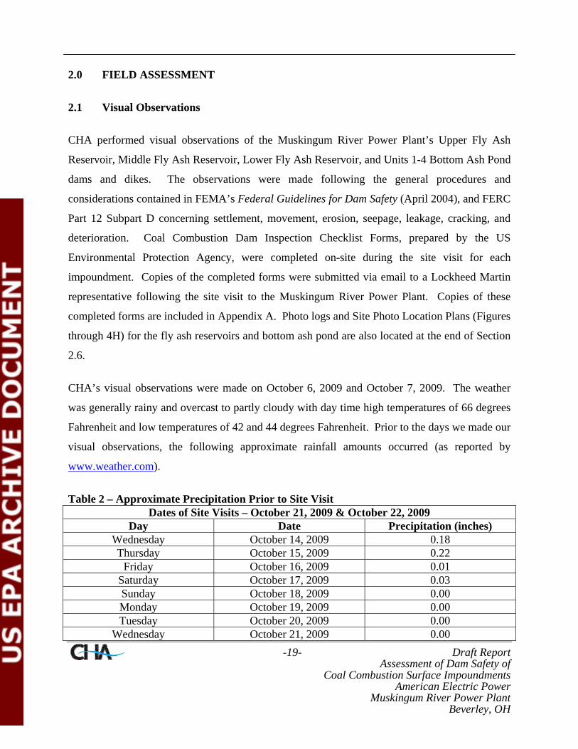
Table 2 – Approximate Precipitation Prior to Site Visit Dates of Site Visits – October 21, 2009 & October 22, 2009
Day Date Precipitation (inches) Wednesday October 14, 2009 0.18 Thursday October 15, 2009 0.22
Friday October 16, 2009 0.01 Saturday October 17, 2009 0.03 Sunday October 18, 2009 0.00 Monday October 19, 2009 0.00 Tuesday October 20, 2009 0.00
Wednesday October 21, 2009 0.00

-20- Draft Report Assessment of Dam Safety of
Coal Combustion Surface Impoundments American Electric Power
Muskingum River Power Plant Beverley, OH
Dates of Site Visits – October 21, 2009 & October 22, 2009 Day Date Precipitation (inches)
Thursday October 22, 2009 0.00 Total Week Prior to Site Visit 0.44
2.2 Visual Observation – Upper Fly Ash Reservoir
CHA performed visual observations of the dams and dikes impounding the Upper Fly Ash
Reservoir. At the time of the site visit, construction was underway to raise the normal operating
pool elevation of the reservoir, which involves increasing the height of the existing Mill Stone
Creek Dam, the No-Name Creek Dam, the Wing Dam, and the Spillway Dam embankments and
the construction of a new dam, known as the Freeboard Dam. According to AEP personnel,
these dams were approximately 5 feet below the modified crest elevations at the time of our site
assessment. The existing Mill Stone Creek Dam, No-Name Creek Dam, Wing Dam, and
Spillway Dam are essentially joined at the top, forming a continuous crest on the north and east
sides of the Upper Fly Ash Reservoir, while the new Freeboard Dam forms the southern limit of
the impoundment. These impoundments are discussed separately in the Sections 2.2.1 through
2.2.5.
2.2.1 Mill Stone Creek Dam
The Mill Stone Creek Dam is approximately 600 feet in length with its centerline aligned in a
northwest to southeast orientation. Its crest area consisted of exposed compacted ash and
appeared stable and free from any abrupt lateral translation, vertical deformation or cracking
(Photo 1). Due to on-going construction activities, including the placement of compacted ash
and an upstream clay zone, ash was exposed in part of the crest and downstream construction
bench (Photo 2). As construction progresses, this ash material will be capped and armored with
stone and rip rap.

-21- Draft Report Assessment of Dam Safety of
Coal Combustion Surface Impoundments American Electric Power
Muskingum River Power Plant Beverley, OH
The downstream embankment slope of the Mill Stone Creek Dam is armored with rip rap (Photo
4). The rip rap is well maintained and in general free from vegetation, with only isolated, dying
woody plants being visible. Rip rap is also used to line the drainage ditches along the southeast
and northwest abutments at the natural hillside contact (Photo Nos. 3 and 8). Rock check dams
were observed in theses drainage ditches.
An isolated seep was observed in the natural hillside at the right (southeast) abutment outside of
the rock lined ditch. This seep appeared to be fairly superficial as a wooden stake could only
penetrate about 6 inches into the soil at this location. It appeared that the wooden stake
penetrated a thin layer of soil cover and came in contact with bedrock. Bedrock is exposed near
the crest of the dam at the northwest (left) abutment (Photo 10). Another isolated feature
observed in the abutment area was a rodent burrow established in the natural hillside. It was
unclear if this burrow had been treated but it appeared to be abandoned.
At mid-slope of the Mill Stone Creek Dam, a bench for embankment monitoring instrumentation
was observed. Slope inclinometers, deformation monuments and piezometers have been
installed (Photo 7). Further down the slope, cleanout and inspection ports for the blanket drain
system located at the base of the dam were noted. The blanket drain discharges via an 18-inch
corrugated HPDE pipe at the toe of the embankment (Photo 5). The pipe conveys the seepage
into an open channel to a seepage collection pond (Photo 6). Seepage exiting this pipe was
observed to be clear at the time of our site visit. Iron precipitate staining from the seepage was
observed on the pipe, the rock lined splash basin, and in the pond. Seepage collected in this
pond is pumped back into the Upper Fly Ash Reservoir. According to AEP personnel, this
collection pond was installed to enable the facility to meet environmental discharge
requirements.
The upstream embankment slope of the Mill Stone Creek Dam is the exposed surface of the
upstream clay zone. In general, the slope appeared to be stable with little erosion evident.
Approximately 3 to 5 feet of the clay slope surface was exposed above the pond surface and part

-22- Draft Report Assessment of Dam Safety of
Coal Combustion Surface Impoundments American Electric Power
Muskingum River Power Plant Beverley, OH
of it had been seeded to provide a stabilizing cover during construction. Weedy vegetation along
with some isolated woody plants was observed at the pond surface interface. It was also evident
that much of the upstream slope impounded part of the saturated ash delta instead of open water.
2.2.2 No-Name Creek Dam
The No-Name Creek Dam is approximately 930 feet in length with its centerline aligned in a
northwest to southeast orientation. It has a similar construction to the Mill Stone Creek Dam
(Photo 11). The crest area of the dam consists of exposed compacted ash and appears to be
stable and free from any abrupt lateral translation, vertical deformation or cracking (Photo 29).
An exposed compacted ash construction bench, a continuation of the construction bench
observed on the Mill Stone Creek Dam was observed near the crest of the dam at its present
elevation (Photo 9).
The downstream embankment slope of the No-Name Creek Dam appears to be stable and with
well maintained rip rap armoring the slope which was observed to be generally free from
vegetation. The armoring was observed to extend to the drainage ditches at the left and right
abutment contacts on the natural hillside (Photos 12 and 16). Rock check dams were observed in
the drainage ditches.
Seepage was observed adjacent to the rock outcrop above the right (southeast) abutment ditch.
This seepage area was just below where AEP personnel have noted seasonal seepage outbreaks
in years past. Seepage was also noted outside the left (northwest) abutment in an area closer to
the embankment toe. Cattail growth in the hillside may indicate that the seepage in this location
is fairly persistent. Where these hillside seeps have been encountered, a short segment of the
abutment ditch has been extended beyond the dam into the hillside (Photo 12).
At approximately ⅓ the vertical embankment height distance down from the crest, a bench for
embankment monitoring instrumentation can be observed, upon which slope inclinometers,
-23- Draft Report Assessment of Dam Safety of
Coal Combustion Surface Impoundments American Electric Power
Muskingum River Power Plant Beverley, OH
deformation monuments and piezometers have been installed (Photo 11). Further down the
slope, cleanout and inspection ports for the blanket drain system installed at the base of the dam
are visible. The blanket drain discharges via an 18-inch corrugated HPDE pipe at the toe of the
embankment (Photo 13). The pipe conveys the seepage into an open channel to a seepage
collection pond (Photo 14). The seepage was observed at this pipe was clear at the time of our
site visit. Iron precipitate staining from the seepage was evident. Seepage in the pond is
collected from the No-Name Creek and the Wing Dams and pumped back into the Upper Fly
Ash Reservoir. According to AEP personnel, this collection pond was installed to meet
environmental discharge requirements.
The upstream embankment slope of the No-Name Creek Dam is the exposed surface of the
upstream clay zone. In general, the slope appeared to be stable with little erosion observed.
Approximately 3 to 5 feet of the clay slope surface is exposed above the pond surface and part of
it had been seeded to provide a stabilizing cover during construction. Weedy vegetation was
observed on the slope near the pond surface, which mostly consists of saturated ash material.
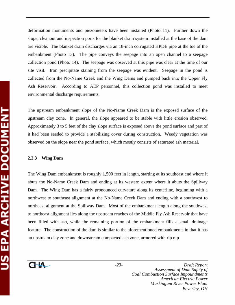
2.2.3 Wing Dam
The Wing Dam embankment is roughly 1,500 feet in length, starting at its southeast end where it
abuts the No-Name Creek Dam and ending at its western extent where it abuts the Spillway
Dam. The Wing Dam has a fairly pronounced curvature along its centerline, beginning with a
northwest to southeast alignment at the No-Name Creek Dam and ending with a southwest to
northeast alignment at the Spillway Dam. Most of the embankment length along the southwest
to northeast alignment lies along the upstream reaches of the Middle Fly Ash Reservoir that have
been filled with ash, while the remaining portion of the embankment fills a small drainage
feature. The construction of the dam is similar to the aforementioned embankments in that it has
an upstream clay zone and downstream compacted ash zone, armored with rip rap.

-24- Draft Report Assessment of Dam Safety of
Coal Combustion Surface Impoundments American Electric Power
Muskingum River Power Plant Beverley, OH
The crest area of the Wing Dam consisted of exposed compacted ash which appears to be stable
and free from any abrupt lateral translation, vertical deformation or cracking (Photo 22). An
exposed compacted ash construction bench, a continuation of the construction bench observed on
the No-Name Creek Dam was observed near the crest of the dam on the portion of the
embankment with the northwest to southeast alignment. A similar bench was noted on the
portion of the embankment bordering the Middle Fly Ash Reservoir, but this was not continuous
with the other portion of the embankment because of an ash construction access ramp (Photo 20)
being incorporated into the dam at the northeast extent of this section.
The downstream embankment slope appears to be stable and is covered with well maintained rip
rap armor, which is in general is free from vegetation (Photos 17 and 21). Some isolated dying
woody plant vegetation was observed on the portion of the embankment filling the drainage
feature immediately adjacent to the No-Name Creek Dam (Photo 19). In this location, the dead
or dying vegetation appeared to be mainly limited to the drainage ditches at the toe where runoff
has likely carried finer grained material to these features where it settled and supported plant
growth.
Cleanout and inspection ports for the blanket drain system at the base of the dam were observed
(Photo 17) near a mid-slope bench on the downstream slope. The blanket drain discharges via a
18-inch diameter corrugated HPDE pipe at the toe of the embankment (Photo 18). Discharge
from this location flowed clear at the time of our site visit. Flow is conveyed via a smaller
diameter pipe to the aforementioned seepage basin below the No-Name Creek Dam, where it is
pumped back into the Upper Fly Ash Reservoir. Iron precipitate was not evident in the discharge
at this embankment.
The upstream embankment slope of the Wing Dam consists of the exposed upstream clay zone
which appears to be stable (Photo Nos. 26 and 28). The slope is intermittently covered with light
grass vegetation for stabilization purposes, depending upon how recently additional clay fill
material had been placed. Isolated erosion rills were observed in locations where the compacted

-25- Draft Report Assessment of Dam Safety of
Coal Combustion Surface Impoundments American Electric Power
Muskingum River Power Plant Beverley, OH
ash was exposed and runoff has concentrated during rain events. However, such erosion features
were not readily observed in the clay material (Photo 27). Broken instrumentation was also
observed in the upstream slope.
2.2.4 Spillway Dam
The Spillway Dam extends roughly 1,200 feet to the west from the Wing Dam. The highest
portion of the embankment occurs at the western terminus of the structure where the spillway or
outfall of the Upper Fly Ash Reservoir is located and the embankment alignment curves to a
more northeast to southwest orientation. The embankment is a zoned, compacted ash and clay
structure similar to the other dams. However, the embankment is constructed with a flatter
downstream slope. The crest area consists of exposed clay soil and appears to be stable and free
from any abrupt lateral translation, vertical deformation or cracking. A temporary construction
bench was not observed in this area.
The downstream embankment slope is approximately 3H:1V and will eventually be grass
covered with rip rap protection at the toe area (Photo 23). At the time of the site visit, only part
of the slope was covered with grass. Other portions had no established vegetation through out
their entire height of the embankment. The downstream embankment slope appears stable.
The rip rap at the toe of the downstream slope has been placed for protection in the event that the
Middle Fly Ash Reservoir pool elevation raises causing water to back up against the Spillway
Dam. The rip rap toe and the rock lined abutment groins connected to it are well maintained and
generally free of vegetation. An exception was noted in the left (west/southwest) abutment groin
where dead or dying weeds was observed
The upstream embankment slope of the Spillway Dam consists of the exposed upstream clay
zone (Photo 24) and appears to be stable with no sloughs or scarps observed at the time of our
site visit. The lower elevation of the upstream embankment slope adjacent to the present pool

-26- Draft Report Assessment of Dam Safety of
Coal Combustion Surface Impoundments American Electric Power
Muskingum River Power Plant Beverley, OH
level was covered with dead or dying seasonal grass vegetation (Photo 25). More recently
placed fill material on the upper portions of the slope was generally not vegetated.
2.2.5 Freeboard Dam
The Freeboard Dam is a new embankment being constructed to accommodate the higher
reservoir pool and provide the necessary freeboard. It is approximately 2,800 feet in length and
is located at the southern rim of the reservoir. The Freeboard Dam embankment is comprised of
an upstream clay zone and a compacted ash downstream zone with rip rap slope protection
(Photo 33). At the time of the site assessment, the embankment was observed to be impounding
less than a foot of water.
The crest consists of exposed clay soil and appears to be stable and free from any abrupt lateral
translation, vertical deformation or cracking. At the time of the site visit, clay fill was being
actively placed and compacted on the eastern end of the crest where the embankment ties in to
the natural ground surface. Fine grading of the crest to shape and seal it to shed water had not
yet occurred.
The downstream embankment slope is partially armored with rip rap to about ½ of the exposed
height (Photo 33). Above this elevation, the compacted ash and clay cap material were exposed.
The slope appears to be stable with no sloughs or scarps observed and the riprap armoring is
generally free of vegetation. Isolated immature woody growth (Photos 30 and 32) was observed.
Exposed soil and ash closer to the crest intermittently exhibited signs of erosion at locations
where surface runoff had been concentrated and less compact material was present. In some
cases the erosion rills were on the order of 12 inches deep, particularly in locations were ash is
exposed.
The downstream toe of the embankment generally terminated on fairly level ground. One
exception to this was approximately 100 feet of embankment length adjacent to a small pond
-27- Draft Report Assessment of Dam Safety of
Coal Combustion Surface Impoundments American Electric Power
Muskingum River Power Plant Beverley, OH
near the western extent of the dam (Photo 31). In this area a monitoring well was observed at the
embankment toe. Another exception was where a large topsoil stockpile has been placed. In this
area the stockpile appears to be inhibiting surface drainage adjacent to the toe.
The upstream embankment slope consists of the exposed clay zone and appears to be stable with
no sloughs or scarps observed at the time of the site visit. The lower elevations of the upstream
slopes adjacent to the present pool level are covered with dead or dying seasonal grass-type
vegetation. More recently placed fill materials on the upper portions of the embankment slope
are generally not vegetated. Isolated deep erosion rills were observed adjacent to the upstream
toe in locations where some grass had been established.
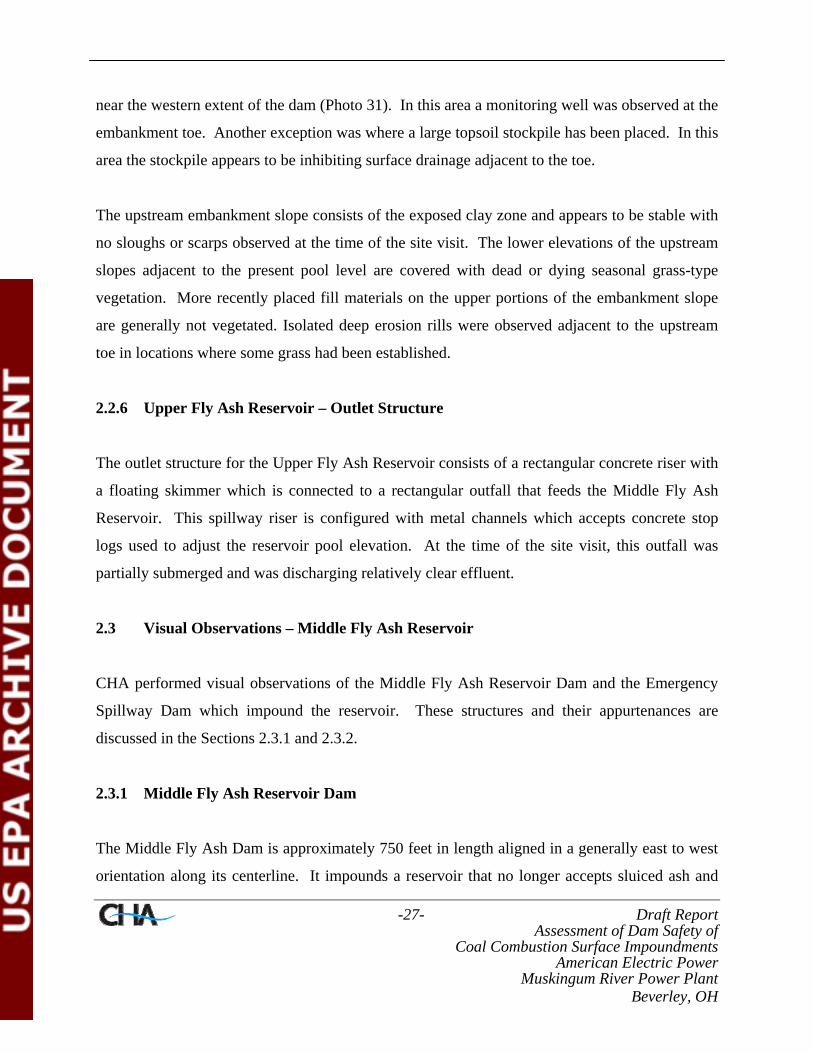
2.2.6 Upper Fly Ash Reservoir – Outlet Structure
The outlet structure for the Upper Fly Ash Reservoir consists of a rectangular concrete riser with
a floating skimmer which is connected to a rectangular outfall that feeds the Middle Fly Ash
Reservoir. This spillway riser is configured with metal channels which accepts concrete stop
logs used to adjust the reservoir pool elevation. At the time of the site visit, this outfall was
partially submerged and was discharging relatively clear effluent.
2.3 Visual Observations – Middle Fly Ash Reservoir
CHA performed visual observations of the Middle Fly Ash Reservoir Dam and the Emergency
Spillway Dam which impound the reservoir. These structures and their appurtenances are
discussed in the Sections 2.3.1 and 2.3.2.
2.3.1 Middle Fly Ash Reservoir Dam
The Middle Fly Ash Dam is approximately 750 feet in length aligned in a generally east to west
orientation along its centerline. It impounds a reservoir that no longer accepts sluiced ash and

-28- Draft Report Assessment of Dam Safety of
Coal Combustion Surface Impoundments American Electric Power
Muskingum River Power Plant Beverley, OH
essentially functions as a secondary settling basin. Activities at this embankment are generally
limited to maintenance, monitoring, and routine grading activities associated with the access road
on the crest of the dam.
The crest of the Middle Fly Ash Reservoir Dam consists of boiler ash outer shell material, which
appears to be stable and free from any abrupt lateral translation, vertical deformation or cracking
(Photos 36 and 37). Maintenance activity associated with embankment monitoring was on going
at the time of our site visit, including installation of a deformation monument and advancement
of a soil boring (Photo 40). Some slight localized rutting associated with these activities was
observed on the crest.
The upstream embankment slope appears to be stable with no sloughs or scarps observed. The
slope is covered with dead or dying vegetation (Photos 40). This vegetation was established on a
soil cover on the upstream slope, which is an apparently an alteration to the original boiler ash
upstream shell design, and made some time after the dam was initially constructed. This soil
cover was also apparent from the cuttings where a soil boring was recently drilled on the dam.
Intermittent erosion rills were observed in this upstream soil cover (Photos 35 and 47).
Approximately 6 to 7 feet of freeboard on the upstream slope was observed at the time of the site
visit, based upon observation of the staff gage mounted on the spillway. A rock groin was
observed on the upstream slope at the western abutment contact which was constructed to
channelize captured runoff and direct it back into the reservoir.
The downstream embankment slope is comprised of the exposed boiler ash outer shell material
and is generally void of vegetative cover (Photos 39, 39, and 44). This area appears to be stable
with no sloughs or scarps observed. The downstream toe of the dam abuts the lower Fly Ash
Reservoir and is submerged. Rip rap has been placed in this area to protect the toe and minimize
beaching erosion. Erosion features were observed in the unarmored surface on this slope, but
were generally isolated and less than 2 or 3 inches in depth. The erosion observed during the site

-29- Draft Report Assessment of Dam Safety of
Coal Combustion Surface Impoundments American Electric Power
Muskingum River Power Plant Beverley, OH
visit may have been the result of the recent drilling activity and not concentrated run-ff from
precipitation.
Rock groins are constructed along the east and west abutment contact at the hillside (Photo 39).
These appear to be well maintained and void of vegetation. According to AEP personnel, the
hillside areas adjacent to these groins had been recently cleared prior to the site visit. An active
seepage pipe was observed emptying into the east rock groin (Photo 45). Seepage at this
location flowed clear, though iron precipitate staining on the rock groin and in the pipe was
apparent. Outside of that area, the groins did not carry discernable water.
2.3.2 Emergency Spillway Dam
The crest of the Emergency Spillway Dam serves as an access drive and is constructed of boiler
ash material. The crest appears to be stable and free from any abrupt lateral translation, vertical
deformation or cracking. Small erosion rills were observed in the crest surface adjacent to the
upstream slope.
The upstream embankment slope consists of exposed gabion baskets (Photo 43) and the
downstream embankment slope is armored with rip rap (Photo 41). These slopes appear to be
stable with no sloughs, scarps, or other deformations observed. In some isolated areas toward
the northeast end of the spillway works, pieces of the rip rap slope protection on the downstream
slope were missing, exposing the underlying geotextile fabric.
On the downstream embankment slope an active seepage drain at the toe of the slope was
observed. Seepage conveyed through the drain was clear and the drain was free from iron
precipitates at the time of the site visit.

-30- Draft Report Assessment of Dam Safety of
Coal Combustion Surface Impoundments American Electric Power
Muskingum River Power Plant Beverley, OH
2.3.3 Middle Fly Ash Dam – Outlet Structure
The outlet structure of the Middle Fly Ash Reservoir is an inclined concrete spillway with a
floating fabric skimmer located on the upstream slope of the dam near the east abutment (Photo
46). This spillway is configured to utilize concrete stop logs to adjust the reservoir pool
elevation (Photo 34). It was clear and unobstructed, actively conveying water at the time of the
site visit. The spillway outfall is a concrete pipe culvert located on the east (right) downstream
abutment, emptying into a rip rap lined splash basin above the Lower Fly Ash Reservoir. Water
exits this splash basin and continues down an exposed rock slope at this location before it enters
the Lower Fly Ash Reservoir (Photos 38 and 39).
2.3.3.1 Middle Fly Ash Dam Emergency Spillway
The emergency spillway for the Middle Fly Ash Reservoir is located roughly 400 to 500 feet to
the southwest of the main dam structure. It is a gabion basket, soil, and boiler ash structure
roughly 450 feet in length founded above a smaller drainage tributary. The control section of the
spillway is roughly 80 feet wide (Photo 42).
2.4 Visual Observations – Lower Fly Ash Reservoir
CHA performed visual observations of the Lower Fly Ash Reservoir Dam which impounds the
Lower Fly Ash Reservoir. This structure and its appurtenances are discussed in the Sections
2.4.1 and 2.4.2.
2.4.1 Lower Fly Ash Reservoir Dam
The Lower Fly Ash Reservoir Dam is approximately 1,500 to 1,600 feet in length and aligned in
a generally east to west orientation along its centerline. It impounds the Lower Fly Ash
Reservoir which accepts sluiced boiler and bottom ash from the Unit 5 generation facility.

-31- Draft Report Assessment of Dam Safety of
Coal Combustion Surface Impoundments American Electric Power
Muskingum River Power Plant Beverley, OH
Activities on this embankment are limited to routine maintenance, monitoring, and grading
activities.
The crest of the Lower Fly Ash Reservoir Dam has a boiler ash and gravel surface, and appears
to be stable and free from any abrupt lateral translation, vertical deformation or cracking (Photos
50, 56, and 60). The crest supports old, inactive sluice lines that traverse most of the
embankment length (Photo 50).
The upstream embankment slope is partially covered with moderate to heavy, dying or dead,
weeds and brushy vegetation and appears to be stable with no sloughs or scarps observed (Photos
49). Slight beaching erosion, up to about a foot in some locations, was observed on the slope.
This is somewhat evident in areas where dried cenospheres have delineated the previous high
water levels in the reservoir and embankment soil has been exposed. Approximately 8 to 10 feet
of freeboard was observed at the time of the site visit, based upon a staff gage formed into the
spillway riser.
The downstream embankment slope has a bench that carries Sparling Road and creates upper and
lower sections of the slope. These upper and lower slopes appear to be stable with no sloughs,
scarps, or deformations observed (Photos 51, 53, and 55). Surface cover varies on the upper
portion of the slope. It is partially vegetated with grasses at elevations closer to the road surface.
At the west abutment area of the slope, dying woody vegetation was observed in what appeared
to be a bottom ash and topsoil mixture. Between this area to about the middle of the
embankment the slope, the surface is protected with small (roughly 4 to 8-inch diameter) rip rap.
Vegetation is generally absent or sparse, while boiler ash, and soil (Photo 53) is evident on the
slope surface over the eastern half of the embankment.
Isolated rodent burrows were observed in the portion of the embankment not armored with rip
rap (Photo Nos. 52 and 54). Dead and dying weedy vegetation and erosion rills (Photo Nos. 60,

-32- Draft Report Assessment of Dam Safety of
Coal Combustion Surface Impoundments American Electric Power
Muskingum River Power Plant Beverley, OH
61, and 63) also are more prevalent in this area, though in some cases the erosion features were
the result of poorly abandoned pipe traces or utility locations as opposed to concentrated runoff.
The lower portion of the downstream embankment slope is protected with rip rap to a toe drain
and buttress. Areas of this armament were partially vegetated with weeds and small brush in the
lower ⅓ of the slope. Upper portions of this rip rap slope, closer to the road, were in better
condition, with sparse, dead or dying weeds. The slope toe terminated in a partially incised basin
which collects stormwater runoff and wastewater from the various facility activities (Photos 58
and 64). An inactive rectangular weir type drain and an active drain pipe conveying seepage was
noted above the pond at the toe buttress. Iron precipitate was observed on the slope at this
location (Photo 59). A small seep was also observed at the very base of the rock buttress area at
the Wastewater Pond.
2.4.2 Lower Fly Ash Reservoir - Outlet Structure
The outlet spillway for the Lower Fly Ash Reservoir is comprised of a rectangular concrete riser
with a skimmer. It is connected to a corrugated metal culvert that conveys water through the
embankment and west of the wastewater basin to a tributary of the Muskingum River (Photo 57).
In addition to having gate openings set to allow normal operating pool levels, this spillway riser
also has fixed levels at the estimated flood elevation to allow it to function as an emergency
spillway. At the time of the site visit, this spillway riser was unobstructed and was actively
discharging relatively clear effluent to the outfall.
2.5 Visual Observations – Units 1-4 Bottom Ash Pond
CHA performed visual observations of the dike impounding the Unit 1-4 Bottom Ash Pond.
This structure and its appurtenances are discussed in the Sections 2.5.1 and 2.5.2.

-33- Draft Report Assessment of Dam Safety of
Coal Combustion Surface Impoundments American Electric Power
Muskingum River Power Plant Beverley, OH
2.5.1 Units 1-4 Bottom Ash Pond
The dikes impounding the active portion of the Units 1-4 Bottom Ash Pond total approximately
3,200 feet in length, with approximately 450 feet of that length actually occurring as an interior
dike within the inactive pond area. The dikes are constructed with compacted bottom ash and
soil, with benches on the south and east dikes. In the inactive pond area, also known as the
dredge spoil area, the eastern dike along the Muskingum River measures roughly 4,400 feet.
The crests of the dikes appear to be stable and free from any abrupt lateral translation, vertical
deformation or cracking (Photos 76, 77, and 84). In the area of the active pond, the crests
consisted of compacted bottom ash. In the inactive or dredge spoil area north of the active pond,
the crests were often obscured by large spoil piles placed on the dikes and were not visible. In
the northern third of the basin the bottom ash crests were visible.
The interior slopes of the dikes are fairly steep and consist of compacted bottom ash (Photos 76,
78, 80, and 86). The dikes appear to be stable with no sloughs, scarps, bulges, or unusual
deformations observed at the time of the site visit. The bottom ash surface does not appear to
readily support vegetation.
The exterior slopes of the dikes have varying characteristics, depending upon their location. The
west dike, which is in general the shortest of the dikes, has a uniform bottom ash surface on the
exterior slope (Photos 65 and 66). This slope is generally free of vegetation and appears to be
well maintained and stable with no sloughs, scarps, bulges, or unusual deformations observed at
the time of the site visit. The toe area is fairly level, wooded, and dry with a drainage swale
between the railroad embankment and the pond.
The exterior slope of the south dike has a bench on the order of about 30 to 40 feet wide
separating the lower slope from the upper portions of the slope (Photo 79). The lower portion of
the slope is fairly steep and consists of compacted soil. A recently cut, heavily vegetated surface
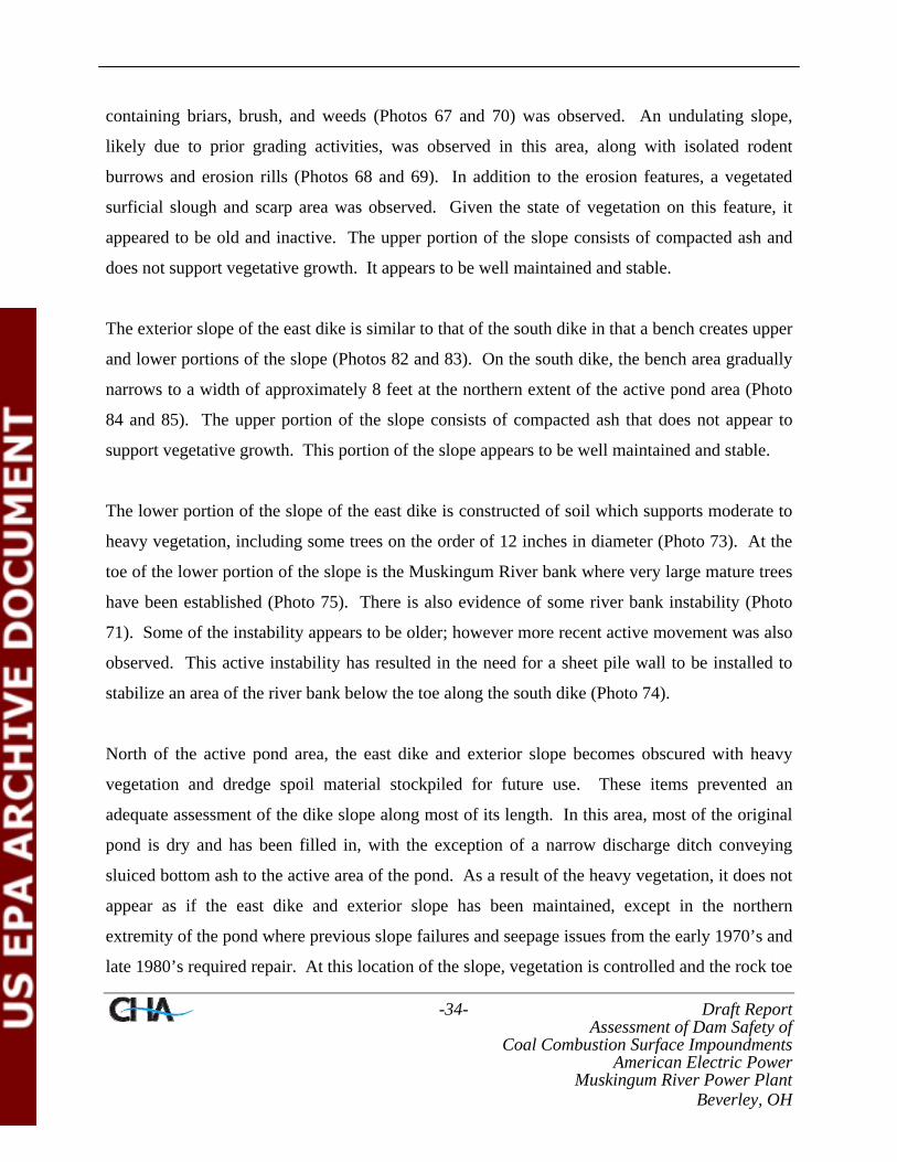
-34- Draft Report Assessment of Dam Safety of
Coal Combustion Surface Impoundments American Electric Power
Muskingum River Power Plant Beverley, OH
containing briars, brush, and weeds (Photos 67 and 70) was observed. An undulating slope,
likely due to prior grading activities, was observed in this area, along with isolated rodent
burrows and erosion rills (Photos 68 and 69). In addition to the erosion features, a vegetated
surficial slough and scarp area was observed. Given the state of vegetation on this feature, it
appeared to be old and inactive. The upper portion of the slope consists of compacted ash and
does not support vegetative growth. It appears to be well maintained and stable.
The exterior slope of the east dike is similar to that of the south dike in that a bench creates upper
and lower portions of the slope (Photos 82 and 83). On the south dike, the bench area gradually
narrows to a width of approximately 8 feet at the northern extent of the active pond area (Photo
84 and 85). The upper portion of the slope consists of compacted ash that does not appear to
support vegetative growth. This portion of the slope appears to be well maintained and stable.
The lower portion of the slope of the east dike is constructed of soil which supports moderate to
heavy vegetation, including some trees on the order of 12 inches in diameter (Photo 73). At the
toe of the lower portion of the slope is the Muskingum River bank where very large mature trees
have been established (Photo 75). There is also evidence of some river bank instability (Photo
71). Some of the instability appears to be older; however more recent active movement was also
observed. This active instability has resulted in the need for a sheet pile wall to be installed to
stabilize an area of the river bank below the toe along the south dike (Photo 74).
North of the active pond area, the east dike and exterior slope becomes obscured with heavy
vegetation and dredge spoil material stockpiled for future use. These items prevented an
adequate assessment of the dike slope along most of its length. In this area, most of the original
pond is dry and has been filled in, with the exception of a narrow discharge ditch conveying
sluiced bottom ash to the active area of the pond. As a result of the heavy vegetation, it does not
appear as if the east dike and exterior slope has been maintained, except in the northern
extremity of the pond where previous slope failures and seepage issues from the early 1970’s and
late 1980’s required repair. At this location of the slope, vegetation is controlled and the rock toe

-35- Draft Report Assessment of Dam Safety of
Coal Combustion Surface Impoundments American Electric Power
Muskingum River Power Plant Beverley, OH
buttress installed to repair the slide is visible at the Muskingum River surface. This repair area
appeared to be stable exhibiting no readily observable sloughs, scarps, bulges, or unusual
deformations. Isolated erosion rills in the slope surface, where sheet flow has become
concentrated, were observed as well as rodent burrows.
2.5.2 Units 1-4 Bottom Ash Pond – Outlet Structure
The outlet structure of the Units 1-4 Bottom Ash Pond is an inclined concrete spillway with a
floating fabric skimmer located on the upstream embankment slope of the dam in the southeast
corner of the pond (Photo 81). The structure was clear and unobstructed, actively conveying
water at the time of the site visit. The spillway outfall is a 48-inch diameter concrete pipe
located on the bank of the Muskingum River (Photo 72).
2.6 Monitoring Instrumentation
Instrumentation has been installed in the Muskingum River Power Plant dams and dikes to
monitor the pheratic surfaces within the embankments and for any movement of the
embankments. A summary of the monitoring instrumentation installed at each of the Ash Pond
Complex Reservoirs and the Units 1-4 Bottom Ash Pond is provided in Section 2.6.1 through
Section 2.6.5.
2.6.1 Pond and Reservoir Water Levels
Pond and reservoir water levels for the period from December 2001 to 2008 were recorded at the
overflow structures by plant personnel. This data is summarized in Table 3.
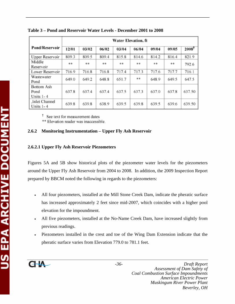
-36- Draft Report Assessment of Dam Safety of
Coal Combustion Surface Impoundments American Electric Power
Muskingum River Power Plant Beverley, OH
Table 3 – Pond and Reservoir Water Levels - December 2001 to 2008
2.6.2 Monitoring Instrumentation – Upper Fly Ash Reservoir
2.6.2.1 Upper Fly Ash Reservoir Piezometers
Figures 5A and 5B show historical plots of the piezometer water levels for the piezometers
around the Upper Fly Ash Reservoir from 2004 to 2008. In addition, the 2009 Inspection Report
prepared by BBCM noted the following in regards to the piezometers:
• All four piezometers, installed at the Mill Stone Creek Dam, indicate the pheratic surface
has increased approximately 2 feet since mid-2007, which coincides with a higher pool
elevation for the impoundment.
• All five piezometers, installed at the No-Name Creek Dam, have increased slightly from
previous readings.
• Piezometers installed in the crest and toe of the Wing Dam Extension indicate that the
pheratic surface varies from Elevation 779.0 to 781.1 feet.
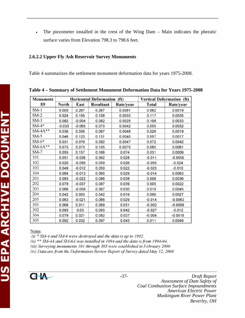
-37- Draft Report Assessment of Dam Safety of
Coal Combustion Surface Impoundments American Electric Power
Muskingum River Power Plant Beverley, OH
• The piezometer installed in the crest of the Wing Dam – Main indicates the pheratic
surface varies from Elevation 798.3 to 798.6 feet.
2.6.2.2 Upper Fly Ash Reservoir Survey Monuments
Table 4 summarizes the settlement monument deformation data for years 1975-2008.
Table 4 – Summary of Settlement Monument Deformation Data for Years 1975-2008

-38- Draft Report Assessment of Dam Safety of
Coal Combustion Surface Impoundments American Electric Power
Muskingum River Power Plant Beverley, OH
The 2009 Inspection Report prepared by BBCM noted the following in regards to the survey
monuments:
• One survey monument which was installed in late 2008 at the Mill Stone Creek Dam has
had no subsequent readings. Two survey monuments (304 and 305) indicate minor
movement (less than 0.13 feet cumulative) towards the northeast. Two of the monuments
(301 and 302) indicate minor movement (less than 0.13 feet cumulative) to the north.
Elevation changes for the five monuments at the Mill Stone Creek Dam have been
erratic, with measurements indicating both upwards and downwards movement since the
initial February 14, 2006 readings.
• Five of the surface monuments installed at the No-Name Creek Dam show minor
movement towards the north; cumulative movements of less than 0.10 feet were
measured since February 14, 2006. Measurements show movements less than 0.05 feet
towards the east. Elevation changes for the five monuments at the No-Name Creek Dam
have been erratic, with measurements indicating both upwards and downwards
movement since the initial February 14, 2006 readings.
• The four survey monuments at the Wing Dam – Extension show cumulative movements
of less than 0.10 feet. The readings show a general trend of movement in the northeast
direction. Elevation changes for the four monuments at the Wing Dam – Extension have
been erratic, with measurements indicating both upwards and downwards movement
since the initial February 14, 2006 readings.
• The three survey monuments at the Wing Dam – Main were installed in late 2008 and no
additional data was available.
• The two survey monuments at the Freeboard Dam were installed in late 2008 and no
additional data was available.

-39- Draft Report Assessment of Dam Safety of
Coal Combustion Surface Impoundments American Electric Power
Muskingum River Power Plant Beverley, OH
2.6.2.3 Upper Fly Ash Reservoir Inclinometers
There are seven inclinometers installed at the Upper Fly Ash Reservoir. The 2009 Inspection
Report prepared by BBCM noted the following in regards to the inclinometers:
• Inclinometer SI-1, located near the toe of the embankment of the Mill Stone Creek Dam,
indicates a slight deflection in both the A and B axis, but less than 0.05 inches. The most
pronounced movement was measured in the top 5 feet of the B-axis.
• Inclinometer SI-5, located on the berm of the downstream face of the Mill Stone Creek
Dam, indicates a slight deflection in both the A and B axis to a depth of approximately 6
feet below grade. This deflection trends in both positive and negative direction for the A
and B axis. Above 6 feet, there is a pronounced deflection in the A-axis positive
direction and to B-axis negative direction. Readings from November 12, 2007 showed a
deflection of approximately 0.10 feet in the A-axis at a depth of approximately 35 feet
below grade. This deflection was not measured in later readings.
• Measurements of Inclinometer SI-2, installed near the toe of the No-Name Creek Dam,
show a slight gradual deflection with cumulative movement of less than 0.10 feet.
However, the deflection curve fluctuates from the negative to the positive. Along the B-
axis there is a pronounced deflection to a depth of approximately 6 feet.
• Readings from Inclinometer SI-8, located on the berm of the downstream face of the No-
Name Creek Dam, show that there is pronounced defection in the positive to a depth of
approximately 8 feet, where it shifts to the negative direction. There have been sets of
readings in between readings with pronounced movement that have indicated near zero
displacement. The inclinometer showed movement up to ¼-inch from February 2008 to
November 2008. In the B-axis, minor displacement was evident in the bottom 30 feet.
Above 30 feet, up to 0.10 feet of displacement was recorded to a depth of 8 feet. Above
8 feet, movement up to ½-inch was recorded.
• Inclinometer SI-3, installed near the toe of the Wing Dam – Extension embankment,
shows a gentle deflection in both the A and B axis that varies from negative to positive

-40- Draft Report Assessment of Dam Safety of
Coal Combustion Surface Impoundments American Electric Power
Muskingum River Power Plant Beverley, OH
from the bottom of the inclinometer up to approximately 6 feet below grade. The
readings showed a noticeable displacement in the negative A-axis and positive B-axis
direction above 6 feet.
• Inclinometer SI-10, located on the berm of the downstream face of the Wing Dam –
Extension embankment, indicated minor displacements along the both the A and B axis
with cumulative measurements generally less than 0.10 inches of movement along the B-
axis in the negative direction with cumulative displacement gradually increasing from the
bottom of the instrument to the top.
• Inclinometer SI-11, installed on the crest of the Freeboard Dam embankment, has had
one reading taken on November 11, 2008 which showed cumulative displacements of
less than 0.006 inches along both the A and B axis.
2.6.3 Monitoring Instrumentation – Middle Fly Ash Reservoir
There appears to be one piezometer located at the Middle Fly Ash Reservoir. The water level
recorded in October 1996 showed that the Piezometer PF level had increased approximately 4 to
4½ feet from the previous year, since then the water level has been steady. The historical data is
presented on Figure 6. No updates for this piezometer have been provided since 2006.
2.6.4 Monitoring Instrumentation – Lower Fly Ash Reservoir
Instrumentation installed at the Lower Fly Ash Reservoir appears to consist of ten piezometers.
Two original piezometers, PH and PG, are operating at the Lower Reservoir Dam. Piezometer
PG is located downstream of the slurry wall and Piezometer PH is located upstream of the slurry
wall. Piezometers P-9201 through P-9208 were installed after the construction of the slurry wall
in the fall of 1992. The historical records of the piezometers are included in Figure 7.
A summary of the piezometer data provided in the 2008 Annual Dam and Dike Inspection
Report is provided below.

-41- Draft Report Assessment of Dam Safety of
Coal Combustion Surface Impoundments American Electric Power
Muskingum River Power Plant Beverley, OH
• The water level in Piezometer PH was relatively uniform following installation of the
slurry wall up until November 1995 through September 2001 when an increase in the
water level occurred to about Elevation 700 feet. This change represents a significant
increase in the water level, although slightly less than the level reported before 1990.
Since 2001, the recorded water levels have remained relatively steady at an average
Elevation of approximately 695 feet.
• Water elevations recorded from Piezometer PG for the period of December 1999 through
December 2005 were within the normal range since the slurry wall was installed (i.e.
Elevation 666 to 670 feet).
• Piezometer P-9201 has shown steady levels since installation, except for one anomalous
reading in March 1999.
• Piezometer P-9202 through P-9208 have shown water elevations approximately within
their normal historical ranges.
2.6.5 Monitoring Instrumentation – Units 1-4 Bottom Ash Pond
There appear to be a total of three piezometers installed at the Units 1-4 Bottom Ash Pond. One
piezometer was installed above the old slide area on the riverbank dike opposite to the
connecting channel and has been monitored since June 1992. The water levels in the piezometer
have shown an increasing trend, as shown in Figure 8, even though the water level in the channel
has remained fairly constant during the monitoring period. Two piezometers, 2W and 3E, were
installed above the old slide are on the riverbank dike in 2005. Water level data from these
piezometers have not been received from the plant to date.
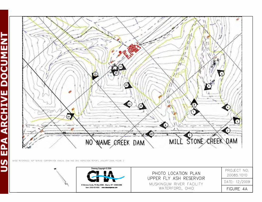
3
2
4
6
5
7
8
1
9
29
16
1110
12
13
14
15

22
26
28
27
20
19
21
17
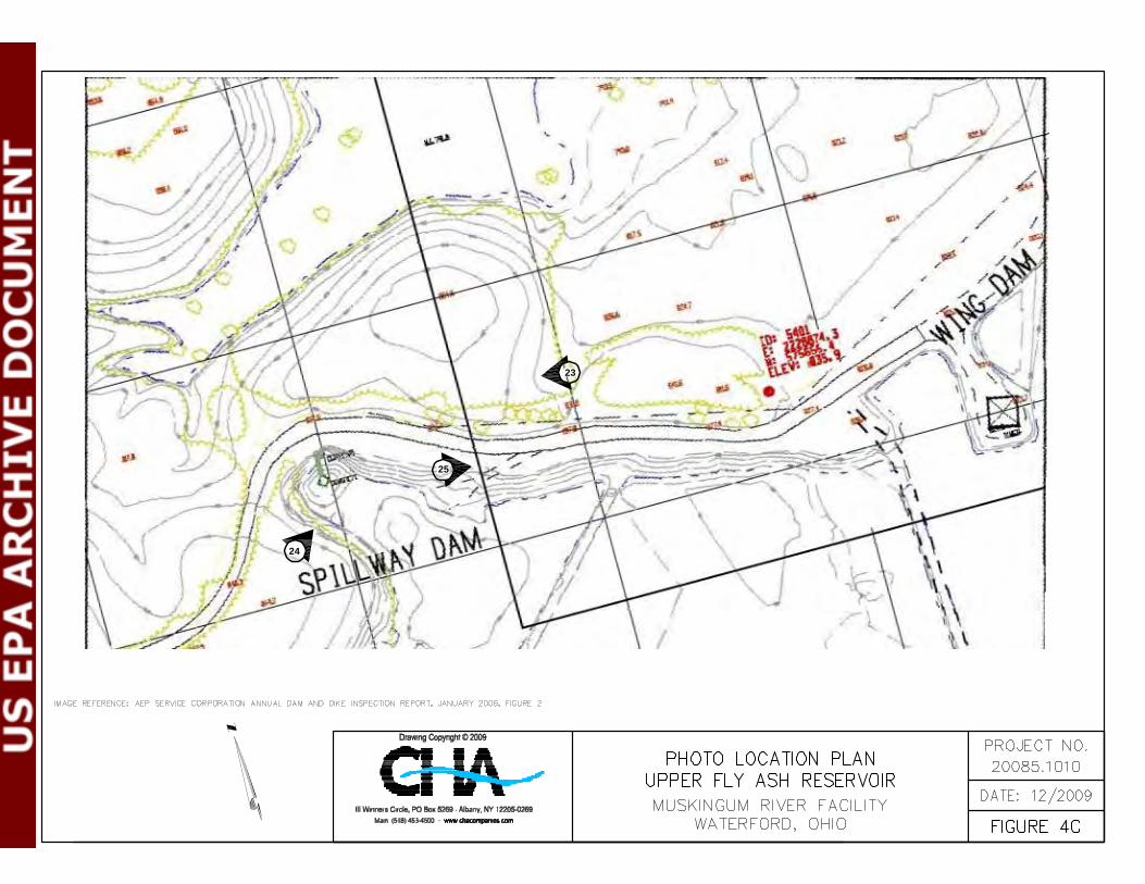
23
25
24
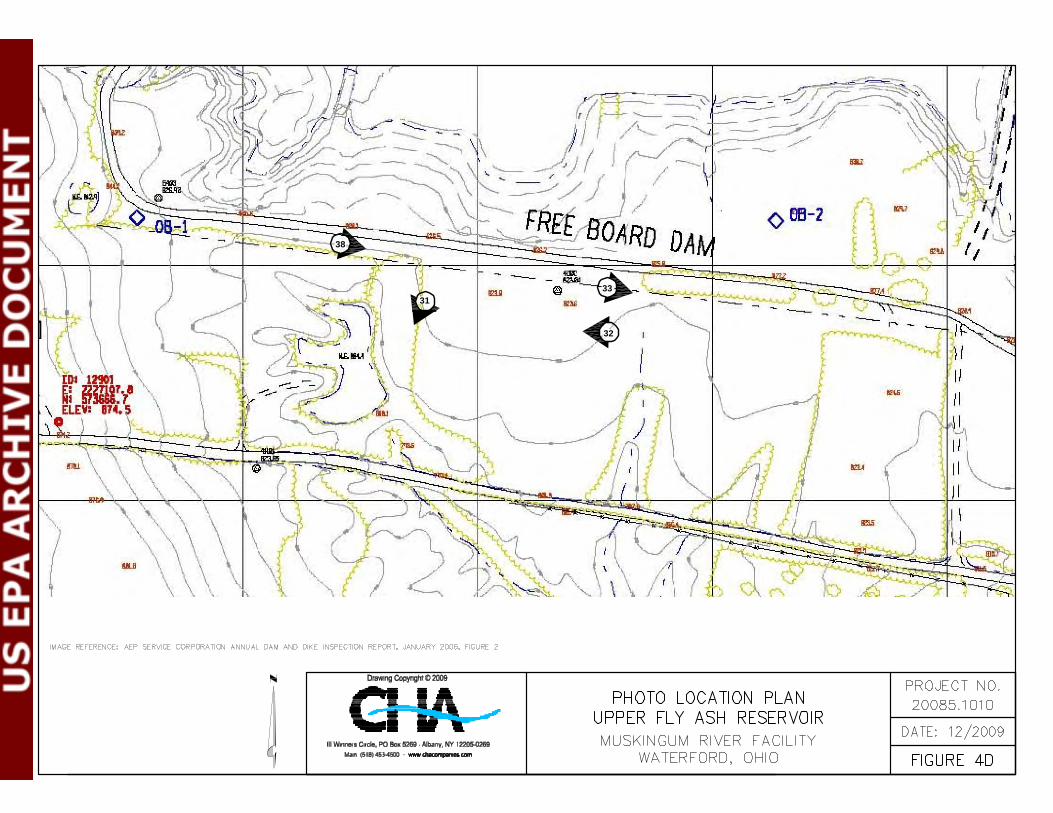
38
3133
32

42
41
44
43
45
39
3437
40
3836
35

50
51
49
53
56

58

65
66
67
72
7071 74
75
76

Page 50
Crest area of Mill Stone Creek Dam, No-Name Creek Dam and part of Wing Dam, looking northwest. Note upstream clay zone and fly ash crest area – active construction.
Crest and downstream fly ash construction bench of the Mill Stone Creek Dam, looking northwest.
AMERICAN ELECTRIC POWER
MUSKINGUM RIVER POWER PLANT WATERFORD, OH
UPPER FLY ASH RESERVIOR
CHA Project No.: 20085.1010.1510 October 21 & October 22, 2009
1
2
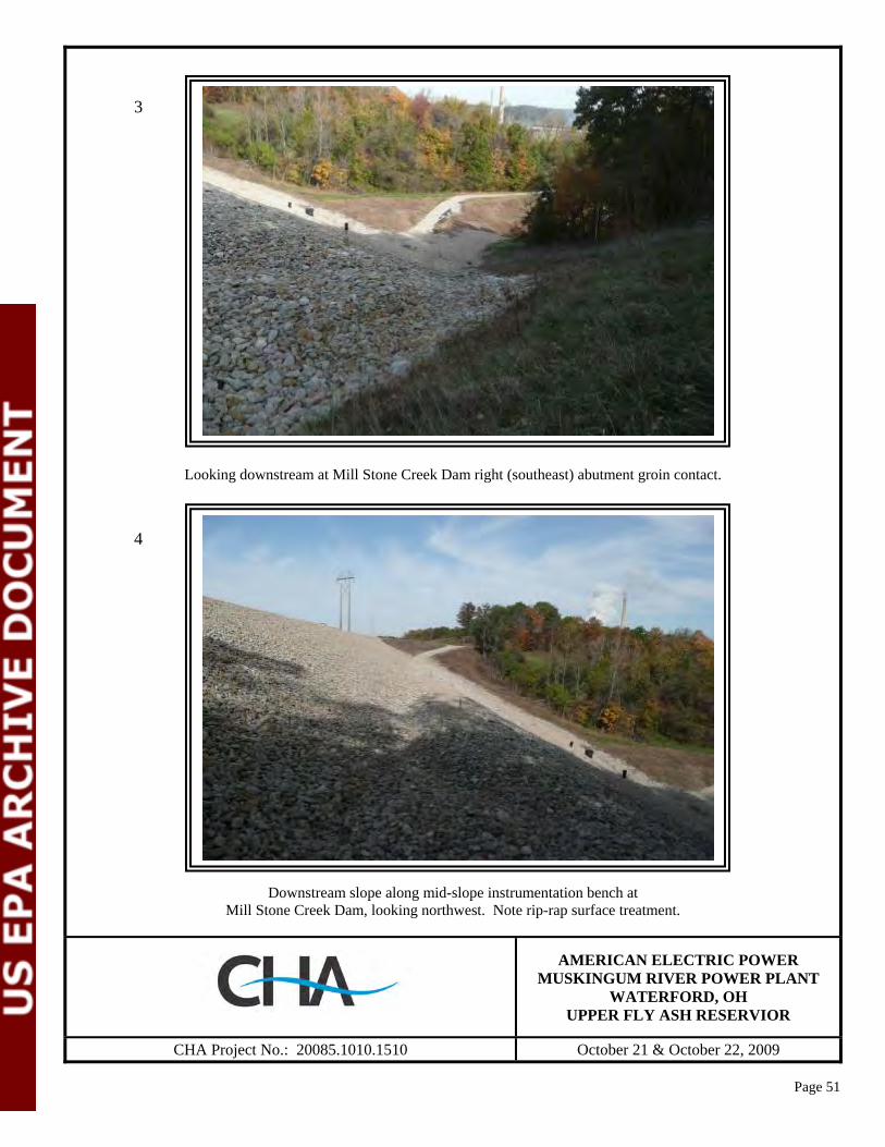
Page 51
Looking downstream at Mill Stone Creek Dam right (southeast) abutment groin contact.
Downstream slope along mid-slope instrumentation bench at Mill Stone Creek Dam, looking northwest. Note rip-rap surface treatment.
AMERICAN ELECTRIC POWER MUSKINGUM RIVER POWER PLANT
WATERFORD, OH UPPER FLY ASH RESERVIOR
CHA Project No.: 20085.1010.1510 October 21 & October 22, 2009
3
4
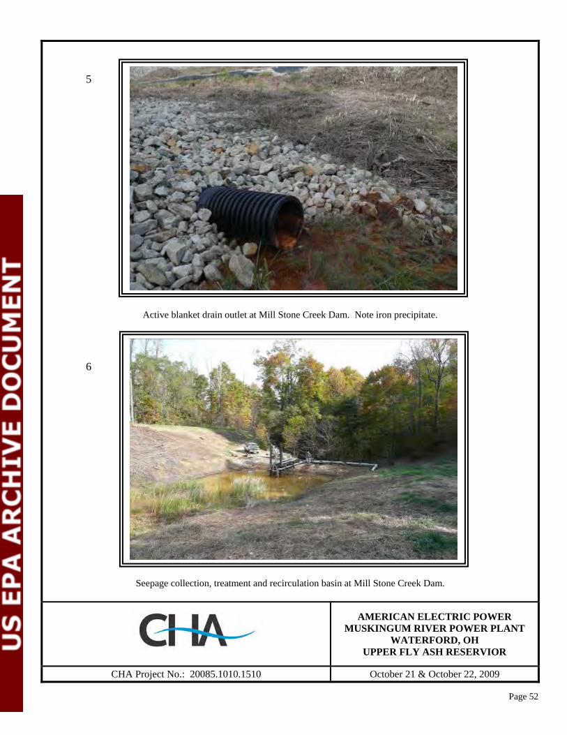
Page 52
Active blanket drain outlet at Mill Stone Creek Dam. Note iron precipitate.
Seepage collection, treatment and recirculation basin at Mill Stone Creek Dam.
AMERICAN ELECTRIC POWER MUSKINGUM RIVER POWER PLANT
WATERFORD, OH UPPER FLY ASH RESERVIOR
CHA Project No.: 20085.1010.1510 October 21 & October 22, 2009
5
6
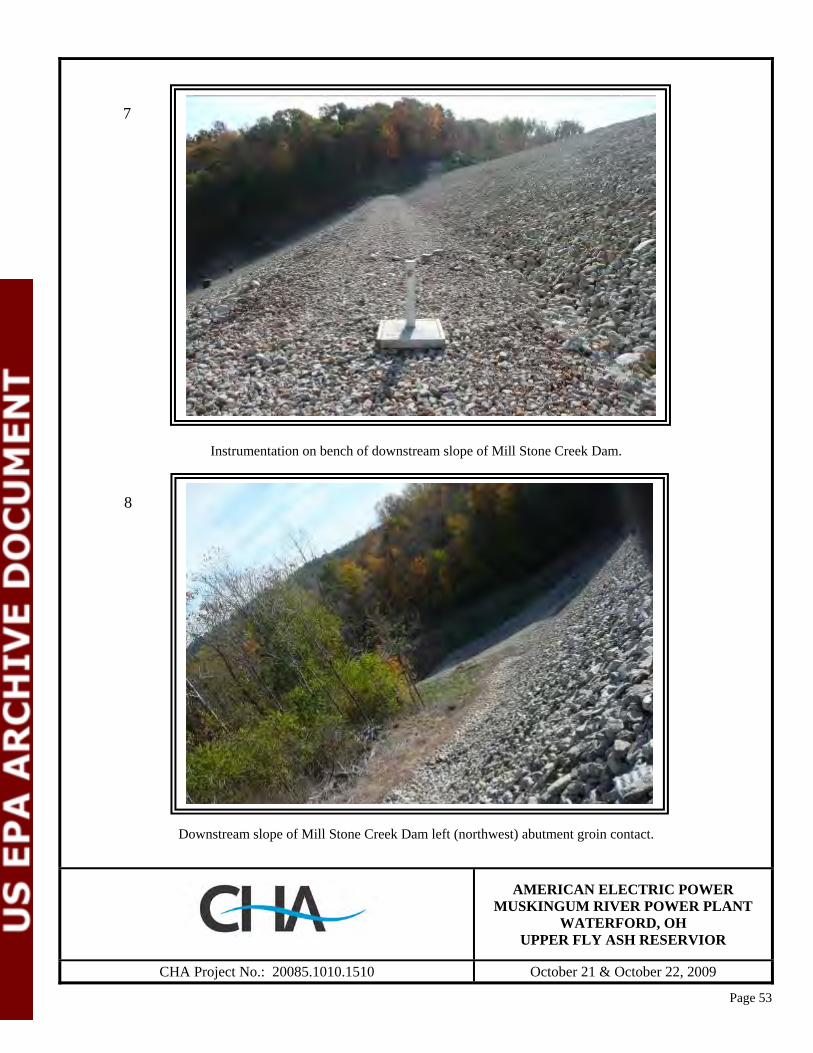
Page 53
Instrumentation on bench of downstream slope of Mill Stone Creek Dam.
Downstream slope of Mill Stone Creek Dam left (northwest) abutment groin contact.
AMERICAN ELECTRIC POWER
MUSKINGUM RIVER POWER PLANT WATERFORD, OH
UPPER FLY ASH RESERVIOR
CHA Project No.: 20085.1010.1510 October 21 & October 22, 2009
7
8

Page 54
Fly ash bench near the crest of the No-Name Creek Dam.
Rock outcrop (sandstone and siltstone) in hillside between No-Name Creek Dam and Mill Stone Creek Dam.
AMERICAN ELECTRIC POWER
MUSKINGUM RIVER POWER PLANT WATERFORD, OH
UPPER FLY ASH RESERVIOR
CHA Project No.: 20085.1010.1510 October 21 & October 22, 2009
9
10

Page 55
No-Name Creek Dam, looking northwest along the downstream slope at bench area.
Slope at right (southeast) abutment contact where extension from groin was constructed to intercept hillside seepage, looking southeast.
AMERICAN ELECTRIC POWER MUSKINGUM RIVER POWER PLANT
WATERFORD, OH UPPER FLY ASH RESERVIOR
CHA Project No.: 20085.1010.1510 October 21 & October 22, 2009
11
12
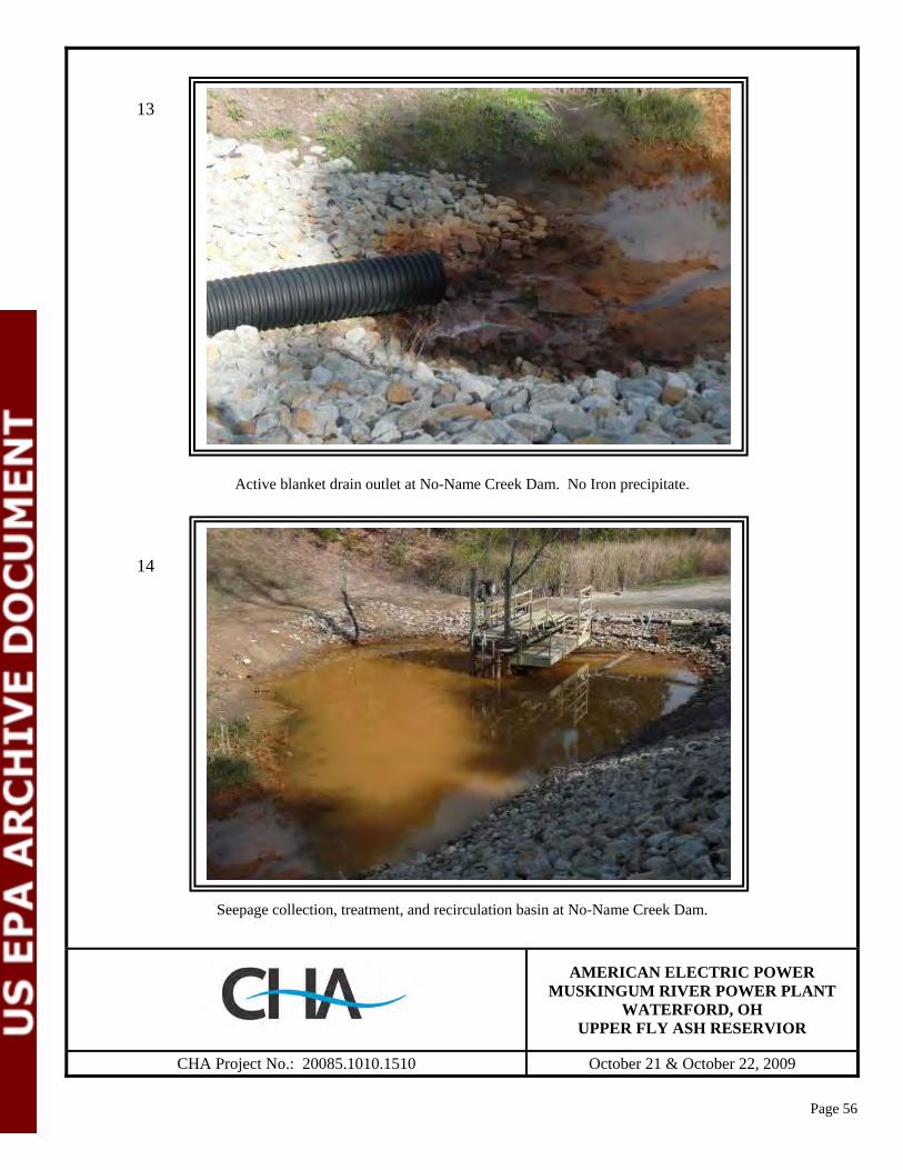
Page 56
Active blanket drain outlet at No-Name Creek Dam. No Iron precipitate.
Seepage collection, treatment, and recirculation basin at No-Name Creek Dam.
AMERICAN ELECTRIC POWER
MUSKINGUM RIVER POWER PLANT WATERFORD, OH
UPPER FLY ASH RESERVIOR
CHA Project No.: 20085.1010.1510 October 21 & October 22, 2009
13
14

Page 57
Downstream slope and left (northwest) abutment groin contact of the No-Name Creek Dam.
Note blanket drain system inspection, access and cleanout ports.
Downstream slope near crest of No-Name Creek Dam at left (northwest) abutment groin contact.
AMERICAN ELECTRIC POWER
MUSKINGUM RIVER POWER PLANT WATERFORD, OH
UPPER FLY ASH RESERVIOR
CHA Project No.: 20085.1010.1510 October 21 & October 22, 2009
15
16

Page 58
Downstream slope and abutment groin of the Wing Dam at right (southeast) abutment contact, looking northwest. Note blanket drain system inspection, access, and cleanout ports in the slope.
Active blanket drain outlet at Wing Dam. Note absence of iron precipitate.
AMERICAN ELECTRIC POWER
MUSKINGUM RIVER POWER PLANT WATERFORD, OH
UPPER FLY ASH RESERVIOR
CHA Project No.: 20085.1010.1510 October 21 & October 22, 2009
17
18
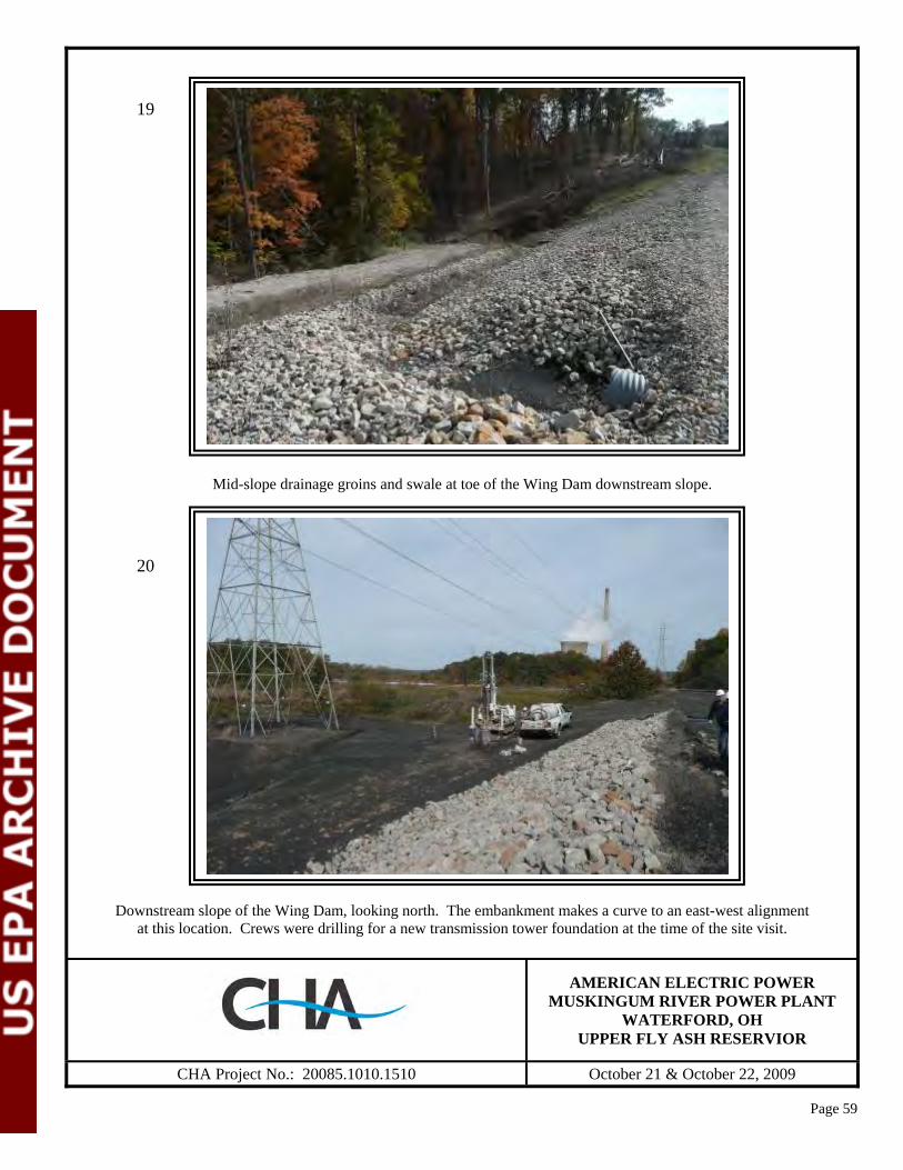
Page 59
Mid-slope drainage groins and swale at toe of the Wing Dam downstream slope.
Downstream slope of the Wing Dam, looking north. The embankment makes a curve to an east-west alignment at this location. Crews were drilling for a new transmission tower foundation at the time of the site visit.
AMERICAN ELECTRIC POWER
MUSKINGUM RIVER POWER PLANT WATERFORD, OH
UPPER FLY ASH RESERVIOR
CHA Project No.: 20085.1010.1510 October 21 & October 22, 2009
19
20

Page 60
Downstream slope of the Wing Dam, looking west. Downstream slope toe forms upstream wall of the Middle Fly Ash Reservoir.
Wing Dam crest, looking east.
AMERICAN ELECTRIC POWER
MUSKINGUM RIVER POWER PLANT WATERFORD, OH
UPPER FLY ASH RESERVIOR
CHA Project No.: 20085.1010.1510 October 21 & October 22, 2009
21
22

Page 61
Downstream slope of the Spillway Dam showing upper grass covered slope and rip-rap protection on the lower portion of the slope, looking west.
Upstream slope of the Spillway Dam, looking northeast. Spillway riser structure is visible in the right of the photo.
AMERICAN ELECTRIC POWER
MUSKINGUM RIVER POWER PLANT WATERFORD, OH
UPPER FLY ASH RESERVIOR
CHA Project No.: 20085.1010.1510 October 21 & October 22, 2009
23
24

Page 62
Upstream slope of the Spillway Dam, looking east towards transition to the Wing Dam. Note grass cover and moderate slope.
Crest and upstream slope of the Wing Dam, looking east.
AMERICAN ELECTRIC POWER
MUSKINGUM RIVER POWER PLANT WATERFORD, OH
UPPER FLY ASH RESERVIOR
CHA Project No.: 20085.1010.1510 October 21 & October 22, 2009
25
26
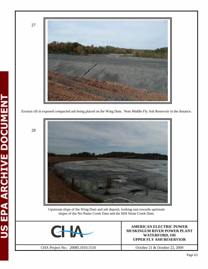
Page 63
Erosion rill in exposed compacted ash being placed on the Wing Dam. Note Middle Fly Ash Reservoir in the distance.
Upstream slope of the Wing Dam and ash deposit, looking east towards upstream
slopes of the No-Name Creek Dam and the Mill Stone Creek Dam.
AMERICAN ELECTRIC POWER
MUSKINGUM RIVER POWER PLANT WATERFORD, OH
UPPER FLY ASH RESERVIOR
CHA Project No.: 20085.1010.1510 October 21 & October 22, 2009
27
28
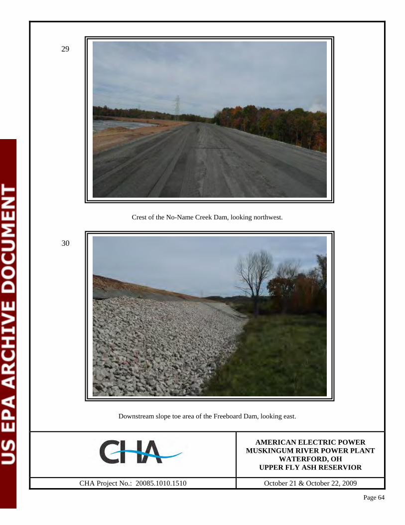
Page 64
Crest of the No-Name Creek Dam, looking northwest.
Downstream slope toe area of the Freeboard Dam, looking east.
AMERICAN ELECTRIC POWER
MUSKINGUM RIVER POWER PLANT WATERFORD, OH
UPPER FLY ASH RESERVIOR
CHA Project No.: 20085.1010.1510 October 21 & October 22, 2009
29
30
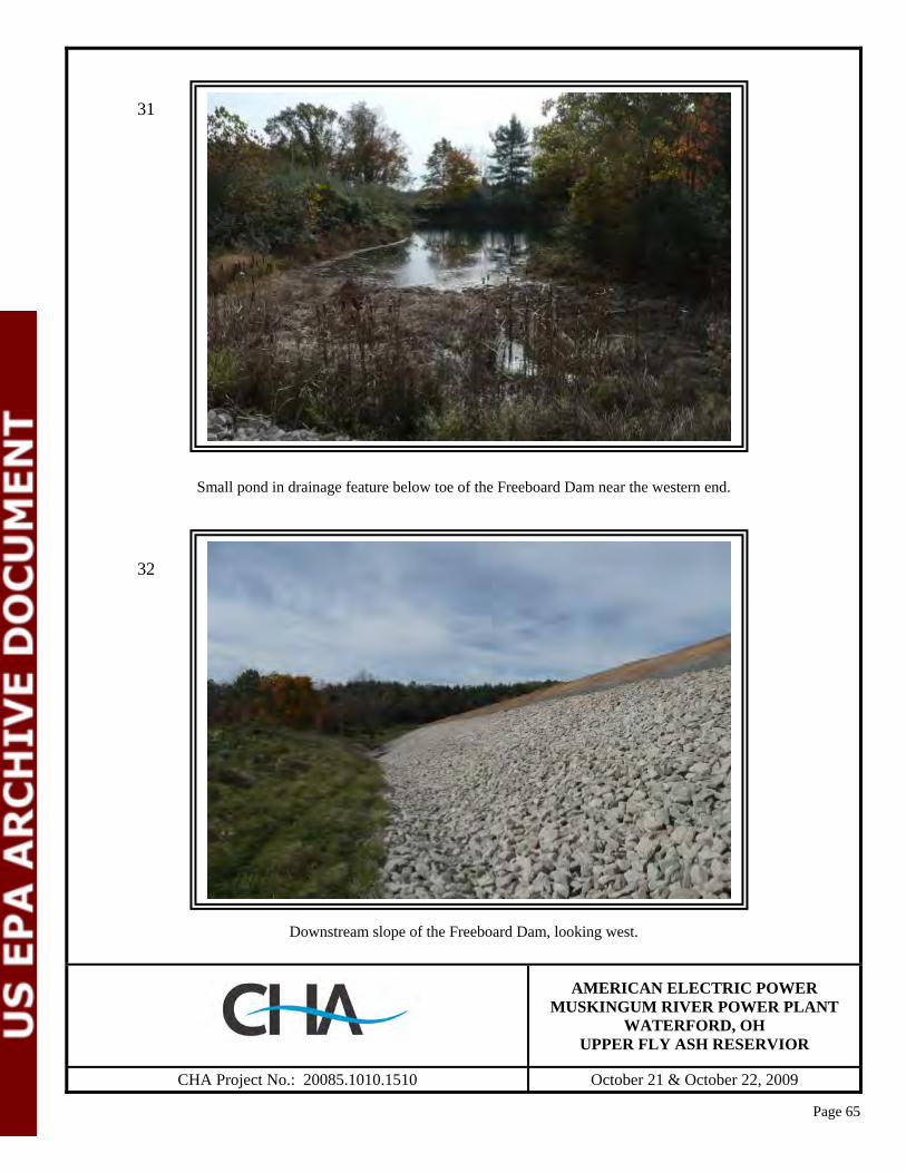
Page 65
Small pond in drainage feature below toe of the Freeboard Dam near the western end.
Downstream slope of the Freeboard Dam, looking west.
AMERICAN ELECTRIC POWER
MUSKINGUM RIVER POWER PLANT WATERFORD, OH
UPPER FLY ASH RESERVIOR
CHA Project No.: 20085.1010.1510 October 21 & October 22, 2009
31
32
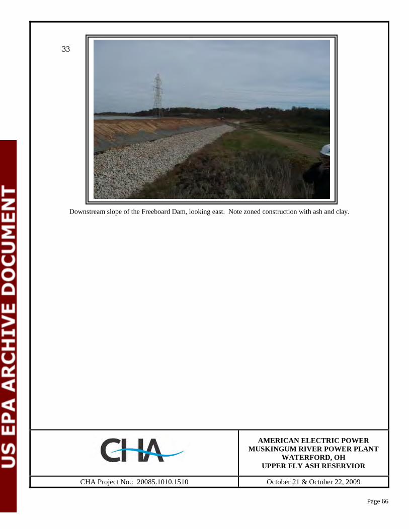
Page 66
Downstream slope of the Freeboard Dam, looking east. Note zoned construction with ash and clay.
AMERICAN ELECTRIC POWER
MUSKINGUM RIVER POWER PLANT WATERFORD, OH
UPPER FLY ASH RESERVIOR
CHA Project No.: 20085.1010.1510 October 21 & October 22, 2009
33

Page 67
Upstream slope and inclined spillway of the Middle Fly Ash Dam, looking east. Note concrete stop logs at top of slope.
Erosion rills on upstream slope of the Middle Fly Ash Dam.
AMERICAN ELECTRIC POWER
MUSKINGUM RIVER POWER PLANT WATERFORD, OH
MIDDLE FLY ASH RESERVIOR
CHA Project No.: 20085.1010.1510 October 21 & October 22, 2009
34
35
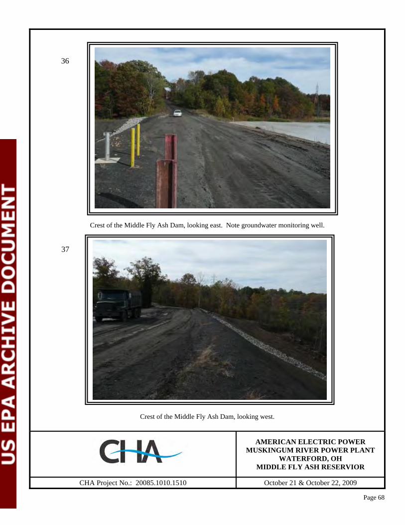
Page 68
Crest of the Middle Fly Ash Dam, looking east. Note groundwater monitoring well.
Crest of the Middle Fly Ash Dam, looking west.
AMERICAN ELECTRIC POWER
MUSKINGUM RIVER POWER PLANT WATERFORD, OH
MIDDLE FLY ASH RESERVIOR
CHA Project No.: 20085.1010.1510 October 21 & October 22, 2009
36
37

Page 69
Looking downstream from the Middle Fly Ash Dam. Note ash slope construction and rip-rap toe protection.
Looking downstream from the Middle Fly Ash Dam. Note effluent above right (east) abutment.
AMERICAN ELECTRIC POWER
MUSKINGUM RIVER POWER PLANT WATERFORD, OH
MIDDLE FLY ASH RESERVIOR
CHA Project No.: 20085.1010.1510 October 21 & October 22, 2009
38
39

Page 70
Upstream slope of the Middle Fly Ash Dam at left (west) abutment rock groin contact, looking west.
Downstream slope of emergency spillway embankment for the Middle Fly Ash Dam, looking northeast.
AMERICAN ELECTRIC POWER
MUSKINGUM RIVER POWER PLANT WATERFORD, OH
MIDDLE FLY ASH RESERVIOR
CHA Project No.: 20085.1010.1510 October 21 & October 22, 2009
40
41

Page 71
Middle Fly Ash Dam, emergency spillway section, looking upstream.
Looking southwest along upstream slope of the gabion emergency spillway.
AMERICAN ELECTRIC POWER
MUSKINGUM RIVER POWER PLANT WATERFORD, OH
MIDDLE FLY ASH RESERVIOR
CHA Project No.: 20085.1010.1510 October 21 & October 22, 2009
42
43

Page 72
Looking east along rock toe drain and rip-rap slope protection of the Middle Fly Ash Dam.
Seepage from hillside above the east abutment contact of the Middle Fly Ash Dam. Note iron precipitate.
AMERICAN ELECTRIC POWER
MUSKINGUM RIVER POWER PLANT WATERFORD, OH
MIDDLE FLY ASH RESERVIOR
CHA Project No.: 20085.1010.1510 October 21 & October 22, 2009
44
45
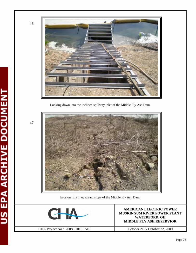
Page 73
Looking down into the inclined spillway inlet of the Middle Fly Ash Dam.
Erosion rills in upstream slope of the Middle Fly Ash Dam.
AMERICAN ELECTRIC POWER
MUSKINGUM RIVER POWER PLANT WATERFORD, OH
MIDDLE FLY ASH RESERVIOR
CHA Project No.: 20085.1010.1510 October 21 & October 22, 2009
46
47

Page 74
Looking north-northwest from crest of the Middle Fly Ash Dam across the Lower Fly Ash Reservoir. .
AMERICAN ELECTRIC POWER
MUSKINGUM RIVER POWER PLANT WATERFORD, OH
MIDDLE FLY ASH RESERVIOR
CHA Project No.: 20085.1010.1510 October 21 & October 22, 2009
48
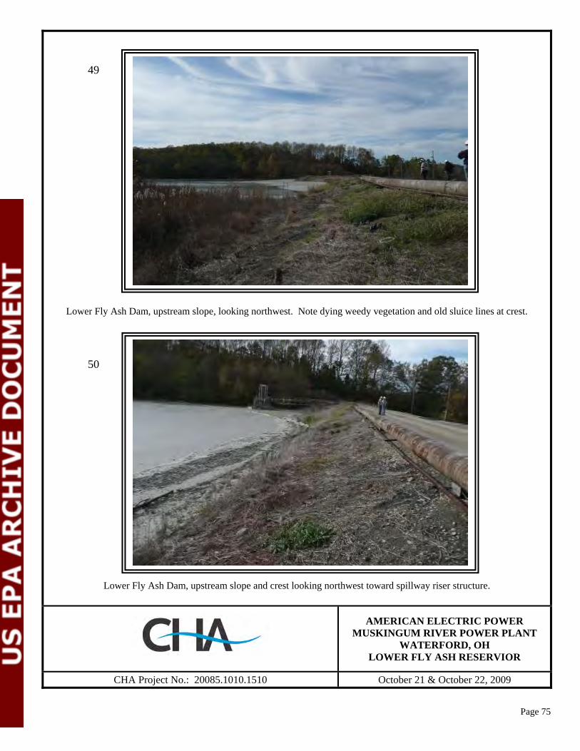
Page 75
Lower Fly Ash Dam, upstream slope, looking northwest. Note dying weedy vegetation and old sluice lines at crest.
Lower Fly Ash Dam, upstream slope and crest looking northwest toward spillway riser structure.
AMERICAN ELECTRIC POWER
MUSKINGUM RIVER POWER PLANT WATERFORD, OH
LOWER FLY ASH RESERVIOR
CHA Project No.: 20085.1010.1510 October 21 & October 22, 2009
49
50
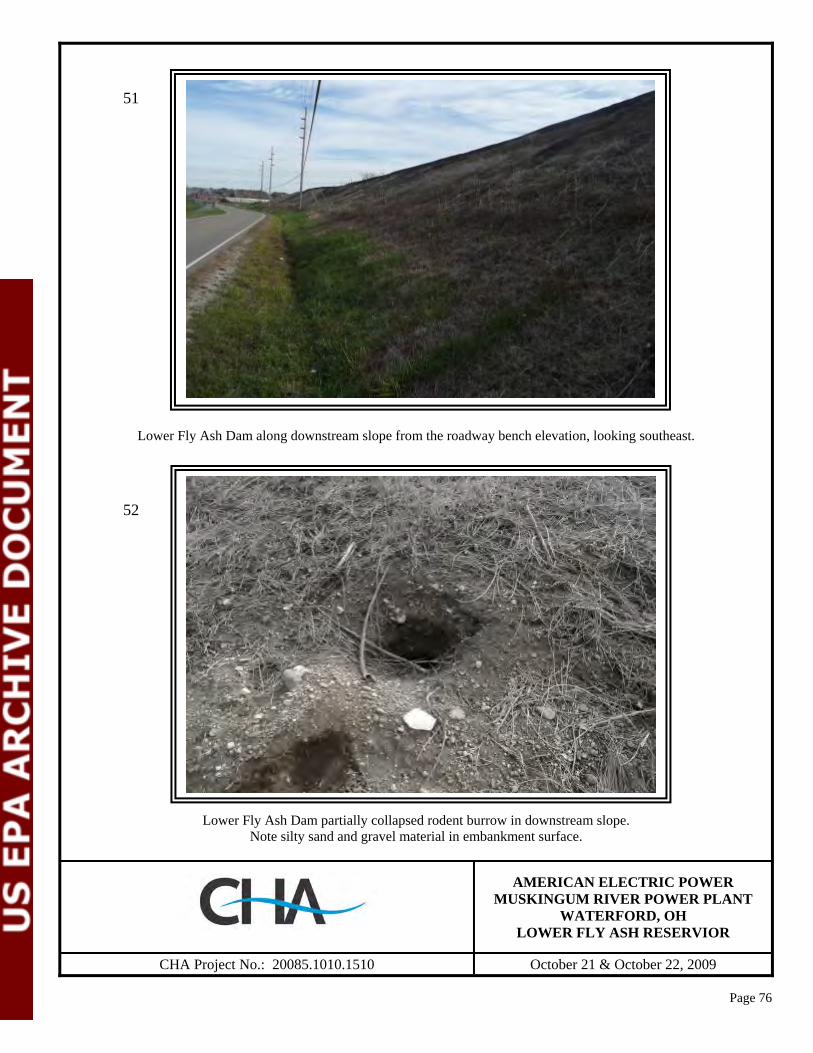
Page 76
Lower Fly Ash Dam along downstream slope from the roadway bench elevation, looking southeast.
Lower Fly Ash Dam partially collapsed rodent burrow in downstream slope. Note silty sand and gravel material in embankment surface.
AMERICAN ELECTRIC POWER MUSKINGUM RIVER POWER PLANT
WATERFORD, OH LOWER FLY ASH RESERVIOR
CHA Project No.: 20085.1010.1510 October 21 & October 22, 2009
51
52

Page 77
Lower Fly Ash Dam along downstream slope near crest, looking northwest. Note bottom ash material at crest elevation.
Rodent burrow on the Lower Fly Ash Dam, southeast facing downstream slope.
AMERICAN ELECTRIC POWER
MUSKINGUM RIVER POWER PLANT WATERFORD, OH
LOWER FLY ASH RESERVIOR
CHA Project No.: 20085.1010.1510 October 21 & October 22, 2009
53
54

Page 78
Lower Fly Ash Dam along southeast facing portion of the downstream slope adjacent to Unit 5 bottom ash sluice lines at the toe of the slope, looking southwest. Note slope undulations resulting from previous grading and dormant surficial sloughing.
Lower Fly Ash Dam upstream slope and crest area along southeast facing portion of the dam.
AMERICAN ELECTRIC POWER
MUSKINGUM RIVER POWER PLANT WATERFORD, OH
LOWER FLY ASH RESERVIOR
CHA Project No.: 20085.1010.1510 October 21 & October 22, 2009
55
56
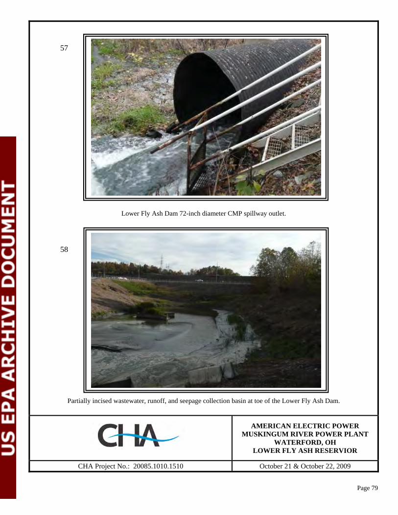
Page 79
Lower Fly Ash Dam 72-inch diameter CMP spillway outlet.
Partially incised wastewater, runoff, and seepage collection basin at toe of the Lower Fly Ash Dam.
AMERICAN ELECTRIC POWER
MUSKINGUM RIVER POWER PLANT WATERFORD, OH
LOWER FLY ASH RESERVIOR
CHA Project No.: 20085.1010.1510 October 21 & October 22, 2009
57
58
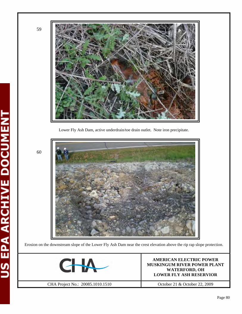
Page 80
Lower Fly Ash Dam, active underdrain/toe drain outlet. Note iron precipitate.
Erosion on the downstream slope of the Lower Fly Ash Dam near the crest elevation above the rip rap slope protection.
AMERICAN ELECTRIC POWER
MUSKINGUM RIVER POWER PLANT WATERFORD, OH
LOWER FLY ASH RESERVIOR
CHA Project No.: 20085.1010.1510 October 21 & October 22, 2009
59
60
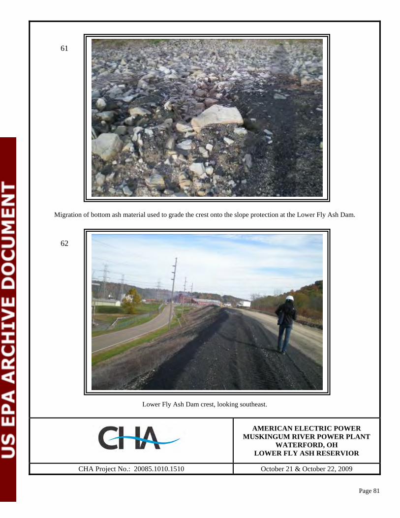
Page 81
Migration of bottom ash material used to grade the crest onto the slope protection at the Lower Fly Ash Dam.
Lower Fly Ash Dam crest, looking southeast.
AMERICAN ELECTRIC POWER
MUSKINGUM RIVER POWER PLANT WATERFORD, OH
LOWER FLY ASH RESERVIOR
CHA Project No.: 20085.1010.1510 October 21 & October 22, 2009
61
62

Page 82
Erosion rills in bottom ash and soil surface on downstream slope of the Lower Fly Ash Dam.
Looking south across the facility water and drainage catch basin at the toe of the Lower Fly Ash Dam. Water entering basin is circulated into the Lower Fly Ash Reservoir.
AMERICAN ELECTRIC POWER MUSKINGUM RIVER POWER PLANT
WATERFORD, OH LOWER FLY ASH RESERVIOR
CHA Project No.: 20085.1010.1510 October 21 & October 22, 2009
63
64
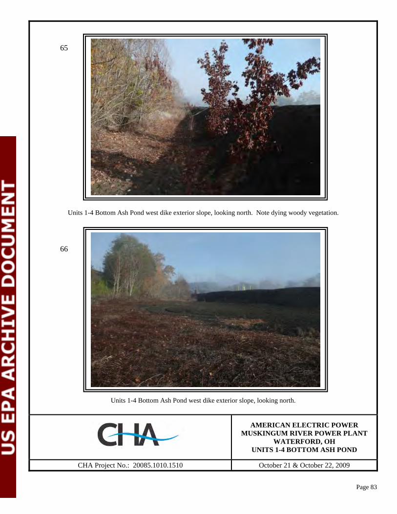
Page 83
Units 1-4 Bottom Ash Pond west dike exterior slope, looking north. Note dying woody vegetation.
Units 1-4 Bottom Ash Pond west dike exterior slope, looking north.
AMERICAN ELECTRIC POWER
MUSKINGUM RIVER POWER PLANT WATERFORD, OH
UNITS 1-4 BOTTOM ASH POND
CHA Project No.: 20085.1010.1510 October 21 & October 22, 2009
65
66

Page 84
Units 1-4 Bottom Ash Pond south dike exterior slope, looking west. Note recently cut heavy vegetation and woody brush.
Rodent burrow on the Units 1-4 Bottom Ash Pond south dike exterior slope.
AMERICAN ELECTRIC POWER
MUSKINGUM RIVER POWER PLANT WATERFORD, OH
UNITS 1-4 BOTTOM ASH POND
CHA Project No.: 20085.1010.1510 October 21 & October 22, 2009
67
68
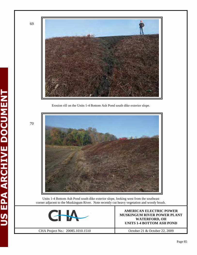
Page 85
Erosion rill on the Units 1-4 Bottom Ash Pond south dike exterior slope.
Units 1-4 Bottom Ash Pond south dike exterior slope, looking west from the southeast corner adjacent to the Muskingum River. Note recently cut heavy vegetation and woody brush.
AMERICAN ELECTRIC POWER
MUSKINGUM RIVER POWER PLANT WATERFORD, OH
UNITS 1-4 BOTTOM ASH POND
CHA Project No.: 20085.1010.1510 October 21 & October 22, 2009
69
70

Page 86
Units 1-4 Bottom Ash Pond east dike exterior slope along the Muskingum River, looking north (or upstream with respect to the river flow). Note relatively large trees at the river bank leaning towards the river.
Units 1-4 Bottom Ash Pond outlet and headwall.
AMERICAN ELECTRIC POWER
MUSKINGUM RIVER POWER PLANT WATERFORD, OH
UNITS 1-4 BOTTOM ASH POND
CHA Project No.: 20085.1010.1510 October 21 & October 22, 2009
71
72
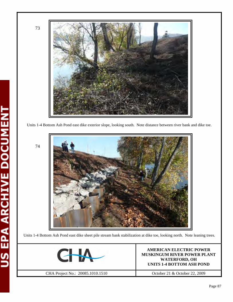
Page 87
Units 1-4 Bottom Ash Pond east dike exterior slope, looking south. Note distance between river bank and dike toe.
Units 1-4 Bottom Ash Pond east dike sheet pile stream bank stabilization at dike toe, looking north. Note leaning trees.
AMERICAN ELECTRIC POWER
MUSKINGUM RIVER POWER PLANT WATERFORD, OH
UNITS 1-4 BOTTOM ASH POND
CHA Project No.: 20085.1010.1510 October 21 & October 22, 2009
73
74
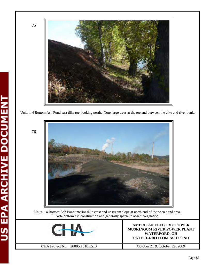
Page 88
Units 1-4 Bottom Ash Pond east dike toe, looking north. Note large trees at the toe and between the dike and river bank.
Units 1-4 Bottom Ash Pond interior dike crest and upstream slope at north end of the open pond area. Note bottom ash construction and generally sparse to absent vegetation.
AMERICAN ELECTRIC POWER
MUSKINGUM RIVER POWER PLANT WATERFORD, OH
UNITS 1-4 BOTTOM ASH POND
CHA Project No.: 20085.1010.1510 October 21 & October 22, 2009
75
76

Page 89
Units 1-4 Bottom Ash Pond west dike crest, looking north.
Units 1-4 Bottom Ash Pond south dike interior slope, looking east.
AMERICAN ELECTRIC POWER
MUSKINGUM RIVER POWER PLANT WATERFORD, OH
UNITS 1-4 BOTTOM ASH POND
CHA Project No.: 20085.1010.1510 October 21 & October 22, 2009
77
78

Page 90
Units 1-4 Bottom Ash Pond south dike upper exterior slope and bench area, looking west. Note bench width in this area is on the order of 30 to 40 feet.
Units 1-4 Bottom Ash Pond east dike interior slope, looking east. Note relatively steep slope.
AMERICAN ELECTRIC POWER
MUSKINGUM RIVER POWER PLANT WATERFORD, OH
UNITS 1-4 BOTTOM ASH POND
CHA Project No.: 20085.1010.1510 October 21 & October 22, 2009
79
80

Page 91
Outfall structure in the south dike of the Units 1-4 Bottom Ash Pond.
Units 1-4 Bottom Ash Pond east dike bench area and upper exterior slope. Bench is on the order of 15 to 20 feet wide in this area with evidence recently mowed dormant vegetation.
AMERICAN ELECTRIC POWER
MUSKINGUM RIVER POWER PLANT WATERFORD, OH
UNITS 1-4 BOTTOM ASH POND
CHA Project No.: 20085.1010.1510 October 21 & October 22, 2009
81
82
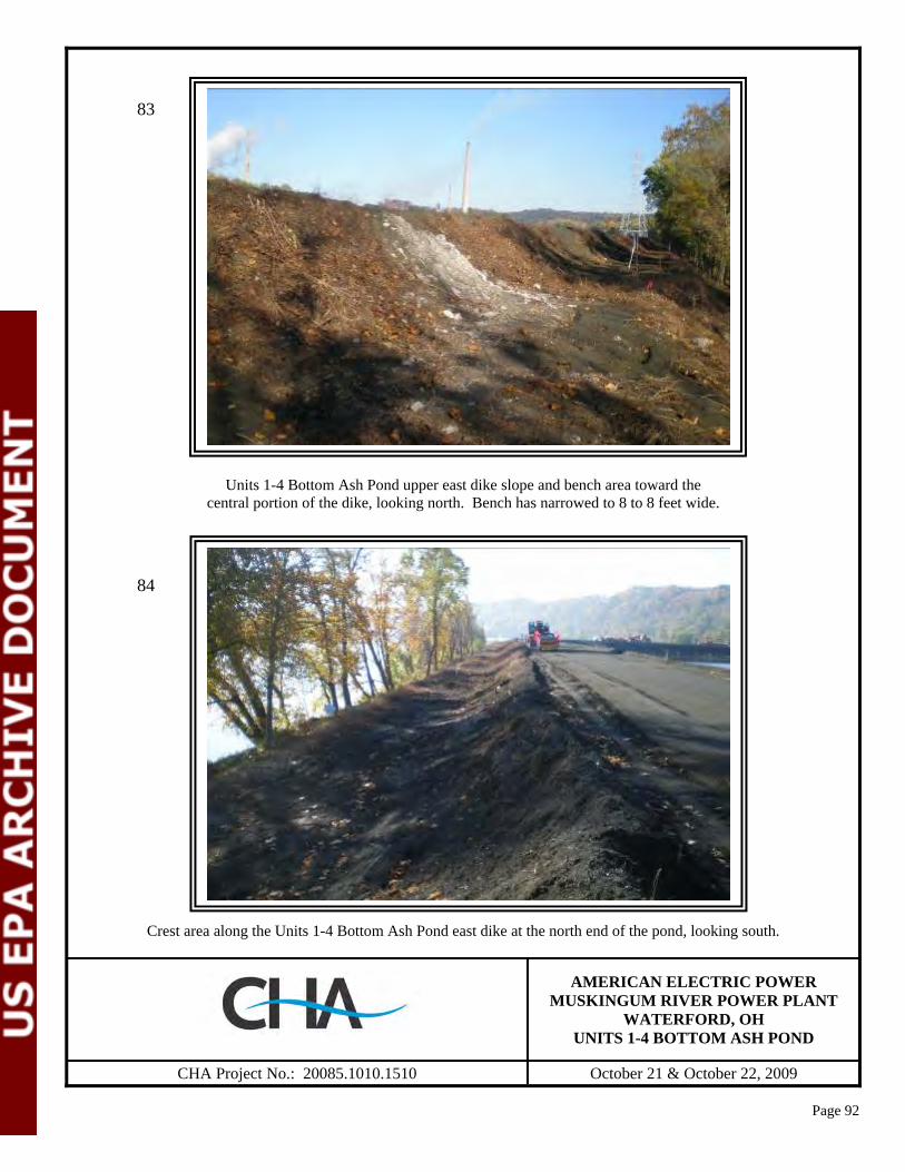
Page 92
Units 1-4 Bottom Ash Pond upper east dike slope and bench area toward the central portion of the dike, looking north. Bench has narrowed to 8 to 8 feet wide.
Crest area along the Units 1-4 Bottom Ash Pond east dike at the north end of the pond, looking south.
AMERICAN ELECTRIC POWER
MUSKINGUM RIVER POWER PLANT WATERFORD, OH
UNITS 1-4 BOTTOM ASH POND
CHA Project No.: 20085.1010.1510 October 21 & October 22, 2009
83
84

Page 93
Crest area along Units 1-4 the Bottom Ash Pond east dike at the north end of the open pond, looking north.
Units 1-4 Bottom Ash Pond east dike interior slope and open pond area, looking south. Note relatively steep slopes and sparse to absent vegetation.
AMERICAN ELECTRIC POWER
MUSKINGUM RIVER POWER PLANT WATERFORD, OH
UNITS 1-4 BOTTOM ASH POND
CHA Project No.: 20085.1010.1510 October 21 & October 22, 2009
85
86

Figure 5A. Historical records of water levels at the Upper Reservoir since 2004
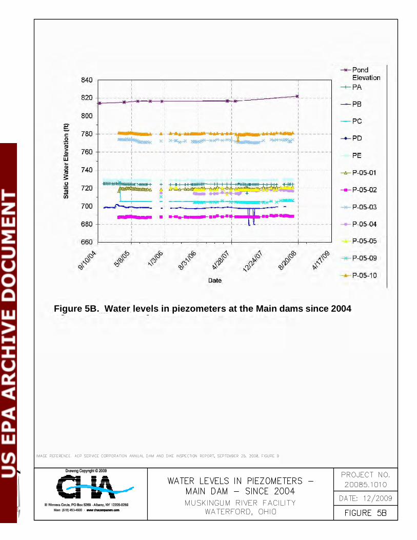
Figure 5B. Water levels in piezometers at the Main dams since 2004
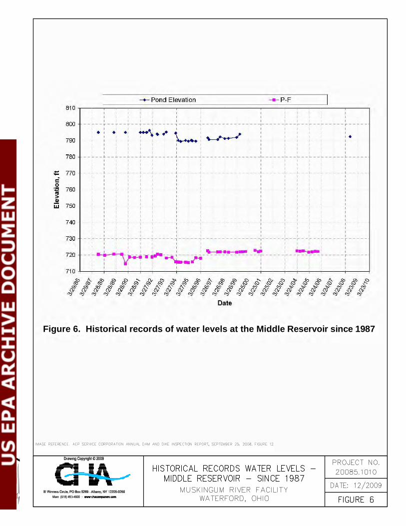
Figure 6. Historical records of water levels at the Middle Reservoir since 1987
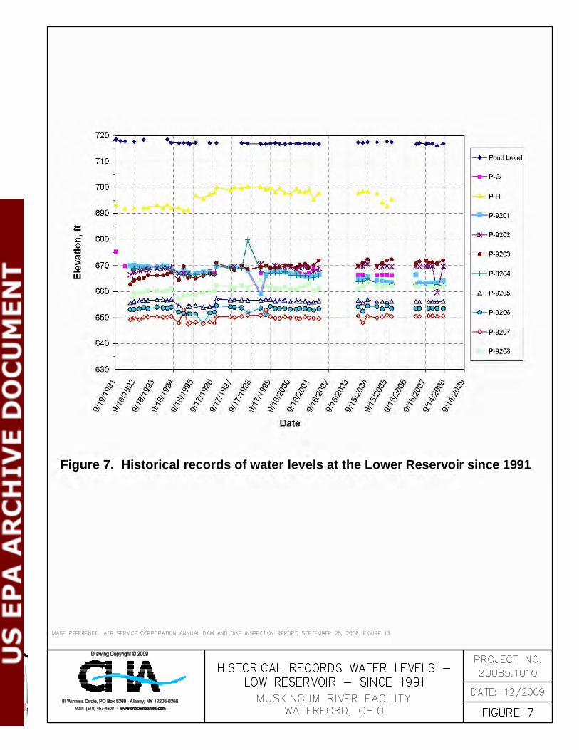
Figure 7. Historical records of water levels at the Lower Reservoir since 1991
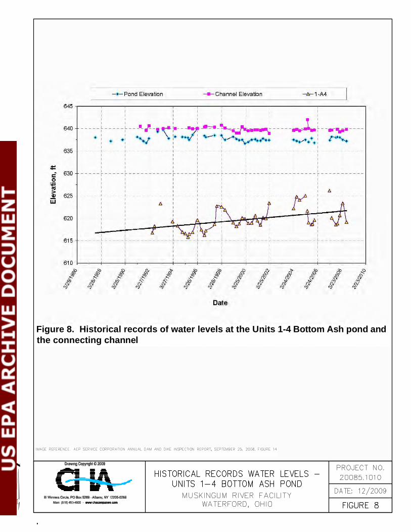
Figure 8. Historical records of water levels at the Units 1-4 Bottom Ash pond andthe connecting channel
-99- Draft Report Assessment of Dam Safety of
Coal Combustion Surface Impoundments American Electric Power
Muskingum River Power Plant Beverley, OH
3.0 DATA EVALUATION
3.1 Design Assumptions
CHA has reviewed the available design assumptions related to the design and analysis of the
stability and hydraulic adequacy of Ash Pond Complex and the Units 1-4 Bottom Ash Pond
available at the time of our site visits and provided to us by AEP. The design assumptions are
listed in the following sections.
3.2 Hydrologic and Hydraulic Design
3.2.1 Hydrologic and Hydraulic Design – Ash Pond Complex
An updated Hydrologic & Hydraulic (H&H) Analysis was performed for the Ash Pond Complex
as part of the Upper Reservoir Dam Raising Engineering Report prepared by AEP Service
Corporation dated December 2003. The Upper Fly Ash Reservoir is currently being raised to
Elevation 842 feet. The maximum operating level has been set at Elevation 837 feet. The
existing principal spillway structure will be raised accordingly. The maximum stoplog elevation
will be 836 feet, which will allow for 8 to 12 inches of flow over the structure during normal
operating conditions. There will be no emergency spillway for the Upper Fly Ash Reservoir.
The Bottom Ash Pond qualifies under the Class I Hazard Classification in the State of Ohio.
Due to these criteria the dams are required to safely pass or store the inflow from the Probable
Maximum Precipitation (PMP) without overtopping, based on the Ohio Administrative Code,
Design Flood for Dams. The initial flood routing indicated that the Middle Fly Ash Reservoir
Dam would be overtopped during both PMP due to the reduced capacity of the principal
spillway. Increasing storage within the Middle Fly Ash Reservoir was not considered feasible
due to the operating procedures for the facility. Therefore, an emergency spillway was proposed.

-100- Draft Report Assessment of Dam Safety of
Coal Combustion Surface Impoundments American Electric Power
Muskingum River Power Plant Beverley, OH
AEP Service Corporation generated design flood hydrographs for the 6 and 24-hour probable
maximum flood and the 6-hour, 50-year recurrence flood using SCS methods in the HEC-1
computer program. Flood routings showed that the combination of the existing Upper Fly Ash
Reservoir principal spillway, the new Middle Fly Ash Reservoir Emergency Spillway and
storage capacities in the Upper and Lower Fly Ash Reservoirs are sufficient to safely pass the
PMF.
3.2.2 Hydrologic and Hydraulic Design – Units 1-4 Bottom Ash Pond
CHA performed an abbreviated Hydrologic & Hydraulic (H&H) Analysis for the Units 1-4
Bottom Ash Pond. The analysis was used to confirm that the pond will adequately store 50% of
the volume generated during the PMF event. The Bottom Ash Pond qualifies under the Class II
Hazard Classification in the State of Ohio. Due to these criteria the dams are required to pass
50% of the full PMF without overtopping, based on the Ohio Administrative Code, Design Flood
for Dams.
The Probable Maximum Precipitation (PMP) of 27.0 inches was provided by the 2009 Inspection
Report, completed by the State of Ohio. This rainfall value was generated through runoff
calculations and reservoir routings using the US Corp of Engineers HEC-1 computer program.
Due to the time of concentration being under 1 hour, the duration of the storm event utilized a
minimum 6-hour storm duration.
Based on the Dam Inventory Sheet the Bottom Ash Pond consists of an 8-foot square concrete
drop box with an 8-foot long low-flow weir and 4-foot stop logs. There is no lake drain or
emergency spillway. The capacity of the basin was based on a recent survey and site visit,
indicating a water surface elevation of 636.9 feet. This elevation is 1.4 feet above the principal
spillway elevation and was modeled as the normal pool elevation. Based on these criteria 50%
of the PMP will safely pass over the 8-foot weir section while providing 8.2 feet of freeboard. A
secondary calculation was completed to verify that the basin was capable of passing the 50%

-101- Draft Report Assessment of Dam Safety of
Coal Combustion Surface Impoundments American Electric Power
Muskingum River Power Plant Beverley, OH
PMF based on the total volume generated from the storm event. The entire volume generated
from the 50% PMF is 75.65 ac-ft. The existing basin is capable of containing this volume
between the elevations of 635.5 feet (principal spillway elevation) and 644.4 feet, while still
maintaining a minimum of 5 feet of freeboard.
Table 5 – Summary of Units 1-4 Bottom Ash Pond Flood Modeling
Pond
Peak Flow Rate
In (cfs)
Peak Flow Rate Out (cfs)
Peak Water
Surface Elev. (ft)
Top of Pond Elev.
(ft)
Free-board
(ft)
Bottom of Pond
Elev. (ft)
(assumed)
Normal Pool Elev.
(ft)
50% PMF
Storage Vol.
(ac-ft)
Bottom Ash Pond
665.5 96.4 641.8 650.0 8.2 617.0¹ 636.9² 75.6
¹ Bottom of pond elevation assumed based on Dam Inventory Sheets. ² Normal Pool elevation based on survey and confirmed by a recent site visit.
Therefore, based on the existing site conditions, basin size, and spillway structure, the Units 1-4
Bottom Ash Pond is capable of passing 50% of the PMF while maintaining a minimum of 5 feet
of freeboard.
3.3 Structural Adequacy & Stability
The Ohio Department of Natural Resources, Division of Water, Dam Safety Program recognizes
“design procedures that have been established by the United States Army Corps of Engineers,
the United States Department of Interior, Interior Bureau of Reclamation, the Federal Energy
Regulatory Commission, The United States Natural Resources Conservation Service, and others
that are generally accepted as sound engineering practice, will be acceptable to the Chief.”
In performing a review of the structural adequacy and stability of the Upper Fly Ash Reservoir,
the Middle Fly Ash Reservoir, the Lower Fly Ash Reservoir and the Units 1-4 Bottom Ash Pond
CHA has compared the computed factor of safety provided in the design documents for the dams

-102- Draft Report Assessment of Dam Safety of
Coal Combustion Surface Impoundments American Electric Power
Muskingum River Power Plant Beverley, OH
and dikes with minimum required factors of safety as outlined by the U.S. Army Corps of
Engineers in EM 1110-2-1902, Table 3-1. The guidance values for minimum factor of safety are
provided in Table 6.
Table 6 - Minimum Safety Factors Required
Load Case Required Minimum Factor of Safety
Steady State Conditions at Present Pool or Maximum Storage Pool Elevation 1.5
Rapid Draw-Down Conditions from Present Pool Elevation 1.3 Maximum Surcharge Pool (Flood) Condition 1.4
Seismic Conditions from Present Pool Elevation 1.0 Liquefaction 1.3
In Sections 3.3.1 through 3.3.4 we discuss our review the available stability analyses for Upper
Fly Ash Reservoir, Middle Fly Ash Reservoir, Lower Fly Ash Reservoir and Units 1-4 Bottom
Ash Pond, respectively.
3.3.1 Subsurface Investigation and Soil Testing Program
Geologic investigation and soil testing programs were performed from November 1973 through
February 1974 to obtain the subsurface geology and engineering characteristics of the soil
materials to be used for the construction of the original dams and dikes. The 1970’s subsurface
investigation consisted of 21 test pits excavated to refusal on the top of rock and 41 borings
where Shelby tube and split-spoon samples were obtained. Bedrock was also sampled as part of
the investigation. Water pressure tests were made in 21 selected holes. A seismic survey was
conducted to supplement the drilling program. In addition, a subsurface investigation consisting
of 32 borings and 6 test pits was conducted for the proposed Upper Fly Ash Reservoir dam and
dike raising in 1996 and 2003, respectively.
Soil testing of foundation materials consisted of visual classification, measuring natural moisture
content, Atterberg limits, grain size analyses, consolidations, permeability, and shear strength by

-103- Draft Report Assessment of Dam Safety of
Coal Combustion Surface Impoundments American Electric Power
Muskingum River Power Plant Beverley, OH
unconsolidated undrained (UU) triaxial tests. Total and effective shear strength parameters were
obtained in the consolidated undrained (CU) triaxial tests and total shear strength parameters
were also obtained on the unconsolidated undrained tests.
Soil testing was conducted on remolded samples from test pits and from plant stockpiles for
borrow fill materials. In addition to those tests listed above, standard Proctor, consolidated
drained (CD) triaxial compression, and relative density tests were also performed.
Table 7 provides shear strength and density parameters for proposed borrow materials for the
raising of the Upper Fly Ash Reservoir dams and dikes.
Table 7 – Shear Strength and Density Parameters for Proposed Borrow Materials
Table 8 provides shear strength and density parameters for existing material the Mill Stone Creek
and No-Name Creek Dams.
Table 8 – Shear Strength and Density Parameters for Mill Stone Creek and No-Name Creek Dams Materials
Table 9 provides shear strength and density parameters for existing material of the Wing Dam.

-104- Draft Report Assessment of Dam Safety of
Coal Combustion Surface Impoundments American Electric Power
Muskingum River Power Plant Beverley, OH
Table 9 – Shear Strength and Density Parameters for the Wing Dam Materials
Table 10 provides shear strength and density parameters for existing material of the Freeboard
Dams.
Table 10 – Shear Strength and Density Parameters for the Freeboard Dams Materials
In addition design compressibility parameters for the impervious and granular fill as well as the
foundation materials were determined based on the results of oedometer tests conducted in the
laboratory. The original settlement estimation as well as the results of the post-construction
settlement recorded to date were reviewed by AEP Service Corporation as part of the Upper
Reservoir Dam Raising Engineering Report to determine the compressibility characteristics of
the impervious (clay) zones of the existing dams.

-105- Draft Report Assessment of Dam Safety of
Coal Combustion Surface Impoundments American Electric Power
Muskingum River Power Plant Beverley, OH
3.3.2 Stability - Upper Fly Ash Reservoir Dams and Dikes
A slope stability analysis was performed for the dams and dikes of the Upper Fly Ash Reservoir
as part of the Upper Reservoir Dam Raising Engineering Report prepared by AEP Service
Corporation dated December 2003. The analyses were performed using the SLOPE/W computer
algorithm of the Geo-Slope suite of programs. The cases for which stability analyses were
performed included:
• Case I – End of Construction;
• Cases II and III – Sudden Drawdown;
• Case IV – Partial Pool;
• Case V – Steady Seepage with Maximum Storage Pool.;
• Case VI – Steady Seepage with Surcharge Pool; and
• Case VII – Earthquake.
Appendix G of the Engineering Report for the Raising of the Upper Flay Ash Reservoir was not
provided to CHA and therefore the stability analyses outputs themselves could not be reviewed.
The factors of safety calculated for each loading condition is however summarized in Sections
3.3.2.1 through 3.3.2.6.
3.3.2.1 Case I – End of Construction
For the end of construction condition unconsolidated undrained shear strengths were used in the
analyses. Table 11 provides a summary of factors of safety calculated for this case.
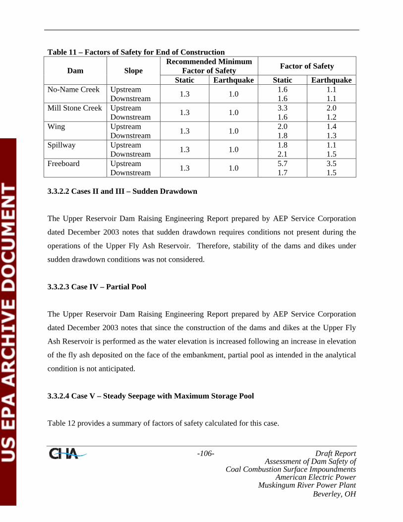
-106- Draft Report Assessment of Dam Safety of
Coal Combustion Surface Impoundments American Electric Power
Muskingum River Power Plant Beverley, OH
Table 11 – Factors of Safety for End of Construction Recommended Minimum
Factor of Safety Factor of Safety Dam Slope Static Earthquake Static Earthquake
No-Name Creek Upstream Downstream 1.3 1.0 1.6
1.6 1.1 1.1
Mill Stone Creek Upstream Downstream 1.3 1.0 3.3
1.6 2.0 1.2
Wing Upstream Downstream 1.3 1.0 2.0
1.8 1.4 1.3
Spillway Upstream Downstream 1.3 1.0 1.8
2.1 1.1 1.5
Freeboard Upstream Downstream 1.3 1.0 5.7
1.7 3.5 1.5
3.3.2.2 Cases II and III – Sudden Drawdown
The Upper Reservoir Dam Raising Engineering Report prepared by AEP Service Corporation
dated December 2003 notes that sudden drawdown requires conditions not present during the
operations of the Upper Fly Ash Reservoir. Therefore, stability of the dams and dikes under
sudden drawdown conditions was not considered.
3.3.2.3 Case IV – Partial Pool
The Upper Reservoir Dam Raising Engineering Report prepared by AEP Service Corporation
dated December 2003 notes that since the construction of the dams and dikes at the Upper Fly
Ash Reservoir is performed as the water elevation is increased following an increase in elevation
of the fly ash deposited on the face of the embankment, partial pool as intended in the analytical
condition is not anticipated.
3.3.2.4 Case V – Steady Seepage with Maximum Storage Pool
Table 12 provides a summary of factors of safety calculated for this case.

-107- Draft Report Assessment of Dam Safety of
Coal Combustion Surface Impoundments American Electric Power
Muskingum River Power Plant Beverley, OH
Table 12 – Factors of Safety for Steady Seepage with Maximum Storage Pool Recommended Minimum
Factor of Safety Factor of Safety Dam Slope Static Earthquake Static Earthquake
No-Name Creek Downstream 1.5 1.0 1.6 1.1 Mill Stone Creek Downstream 1.5 1.0 1.5 1.5 Wing Downstream 1.5 1.0 1.5 1.1 Spillway Downstream 1.5 1.0 2.0 1.5 Freeboard Downstream 1.5 1.0 1.8 1.3
3.3.2.5 Case VI – Steady Seepage with Surcharge Pool
Table 13 provides a summary of factors of safety calculated for this case.
Table 13 – Factors of Safety for Steady Seepage with Surcharge Pool Recommended Minimum
Factor of Safety Factor of Safety Dam Slope Static Earthquake Static Earthquake
No-Name Creek Downstream 1.4 NA 1.6 1.1 Mill Stone Creek Downstream 1.4 NA 1.4 1.1 Wing Downstream 1.4 NA 1.5 1.1 Spillway Downstream 1.4 NA 2.0 1.5 Freeboard Downstream 1.4 NA 1.7 1.3 NA – Not Applicable
3.3.2.6 Case VII – Earthquake Loading Condition
For the location of the Upper Fly Ash Reservoir, a horizontal acceleration equal to 0.15g was
selected as the design event. The Upper Reservoir Dam Raising Engineering Report prepared by
AEP Service Corporation dated December 2003 notes this value has a 90 percent probability of
not being exceed in 250 years.

-108- Draft Report Assessment of Dam Safety of
Coal Combustion Surface Impoundments American Electric Power
Muskingum River Power Plant Beverley, OH
A deformation analysis was completed by AEP Service Corporation using SIGMA/W, a finite
elements algorithm part of the Geo-Slope suite of programs. Table 14 provides a summary of the
total displacement at the maximum sections of the dams and dikes.
Table 14 – Estimated Total Displacement at the Maximum Section of the Dams and Dikes
The Upper Reservoir Dam Raising Engineering Report noted that the values of magnitude
calculated are within the values commonly anticipated for embankments of the size to be built as
a result of the proposed raising.
3.3.2 Stability - Middle Fly Ash Reservoir Dam
The stability of the Main Dam at the Middle Reservoir was evaluated in September 2009 by AEP
Service Corporation. The stability of the Main Dam had been assessed by Casagrande
Consultants in 1974 based upon the geometry of the dam at the time. Using a block failure in the
stability analysis a factor of safety of 1.42 was calculated for the downstream slope under
maximum possible pool elevation of 800 feet. This factor of safety was deemed unsatisfactory
and Casagrande recommended that the downstream slope be reduced to 2.5H:1V. Reportedly,
several geometric modifications of the downstream slope have been performed since 1974 that
have led to its current configuration.
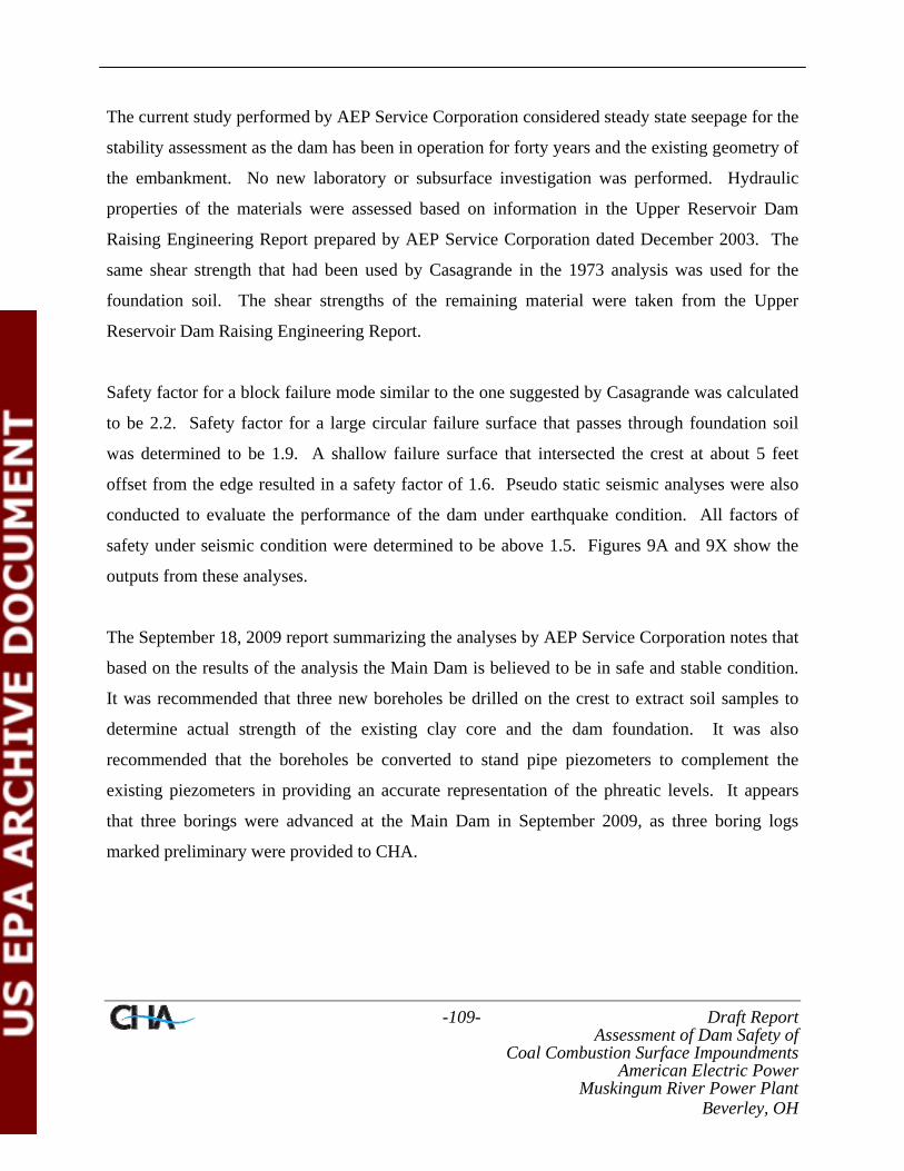
-109- Draft Report Assessment of Dam Safety of
Coal Combustion Surface Impoundments American Electric Power
Muskingum River Power Plant Beverley, OH
The current study performed by AEP Service Corporation considered steady state seepage for the
stability assessment as the dam has been in operation for forty years and the existing geometry of
the embankment. No new laboratory or subsurface investigation was performed. Hydraulic
properties of the materials were assessed based on information in the Upper Reservoir Dam
Raising Engineering Report prepared by AEP Service Corporation dated December 2003. The
same shear strength that had been used by Casagrande in the 1973 analysis was used for the
foundation soil. The shear strengths of the remaining material were taken from the Upper
Reservoir Dam Raising Engineering Report.
Safety factor for a block failure mode similar to the one suggested by Casagrande was calculated
to be 2.2. Safety factor for a large circular failure surface that passes through foundation soil
was determined to be 1.9. A shallow failure surface that intersected the crest at about 5 feet
offset from the edge resulted in a safety factor of 1.6. Pseudo static seismic analyses were also
conducted to evaluate the performance of the dam under earthquake condition. All factors of
safety under seismic condition were determined to be above 1.5. Figures 9A and 9X show the
outputs from these analyses.
The September 18, 2009 report summarizing the analyses by AEP Service Corporation notes that
based on the results of the analysis the Main Dam is believed to be in safe and stable condition.
It was recommended that three new boreholes be drilled on the crest to extract soil samples to
determine actual strength of the existing clay core and the dam foundation. It was also
recommended that the boreholes be converted to stand pipe piezometers to complement the
existing piezometers in providing an accurate representation of the phreatic levels. It appears
that three borings were advanced at the Main Dam in September 2009, as three boring logs
marked preliminary were provided to CHA.

-110- Draft Report Assessment of Dam Safety of
Coal Combustion Surface Impoundments American Electric Power
Muskingum River Power Plant Beverley, OH
3.3.3 Stability – Lower Fly Ash Reservoir
The stability of the dam at the Lower Reservoir was evaluated in September 2009 by AEP
Service Corporation. It should be noted that a more comprehensive study that includes seepage
analyses is currently in progress. It appears that four borings were advanced at the Lower
Reservoir Dam on October 2009, as four boring logs marked preliminary were provided to CHA.
The preliminary study performed by AEP Service Corporation considered steady state seepage
for the stability assessment as the dam has been in operation for forty years. No new laboratory
or subsurface investigation was performed. The shear strength of the boiler slag was taken from
the 2003 Upper Reservoir Dam Raising Engineering Report. The shear strength of the
foundation soil was taken to be the same as that used by Casagrande in 1974 to assess the
stability of the Middle Reservoir Dam. The phreatic surface was established based on the
measured water levels in the piezometers at the crest, the road and the toe area.
Safety factor for a block failure mechanism passing through the foundation of the embankment
was calculated to be 2.2. Safety factor for a large circular failure surface that passes through
foundation soil was determined to be 2.1. Shallow failure surfaces at the upper and lower
portions of the downstream slope resulted in a factor of safety of 2.0 for both portions. Pseudo
static seismic analyses were also conducted to evaluate the performance of the dam under
earthquake condition. All factors of safety under seismic condition were determined to be 1.7 or
higher. Figures 10A and 10X show the outputs from preliminary these analyses.
The September 18, 2009 report summarizing the analyses by AEP Service Corporation notes that
based on the results of the analysis the Main Dam of the Lower Reservoir is believed to be in
safe and stable condition. It was recommended that four new boreholes be drilled on the crest to
extract soil samples to determine actual strength of the existing clay core and the dam
foundation. It was also recommended that the boreholes be converted to stand pipe piezometers
to complement the existing piezometers.
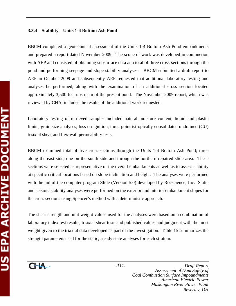
-111- Draft Report Assessment of Dam Safety of
Coal Combustion Surface Impoundments American Electric Power
Muskingum River Power Plant Beverley, OH
3.3.4 Stability – Units 1-4 Bottom Ash Pond
BBCM completed a geotechnical assessment of the Units 1-4 Bottom Ash Pond embankments
and prepared a report dated November 2009. The scope of work was developed in conjunction
with AEP and consisted of obtaining subsurface data at a total of three cross-sections through the
pond and performing seepage and slope stability analyses. BBCM submitted a draft report to
AEP in October 2009 and subsequently AEP requested that additional laboratory testing and
analyses be performed, along with the examination of an additional cross section located
approximately 3,500 feet upstream of the present pond. The November 2009 report, which was
reviewed by CHA, includes the results of the additional work requested.
Laboratory testing of retrieved samples included natural moisture content, liquid and plastic
limits, grain size analyses, loss on ignition, three-point istropically consolidated undrained (CU)
triaxial shear and flex-wall permeability tests.
BBCM examined total of five cross-sections through the Units 1-4 Bottom Ash Pond; three
along the east side, one on the south side and through the northern repaired slide area. These
sections were selected as representative of the overall embankments as well as to assess stability
at specific critical locations based on slope inclination and height. The analyses were performed
with the aid of the computer program Slide (Version 5.0) developed by Rocscience, Inc. Static
and seismic stability analyses were performed on the exterior and interior embankment slopes for
the cross sections using Spencer’s method with a deterministic approach.
The shear strength and unit weight values used for the analyses were based on a combination of
laboratory index test results, triaxial shear tests and published values and judgment with the most
weight given to the triaxial data developed as part of the investigation. Table 15 summarizes the
strength parameters used for the static, steady state analyses for each stratum.

-112- Draft Report Assessment of Dam Safety of
Coal Combustion Surface Impoundments American Electric Power
Muskingum River Power Plant Beverley, OH
Table 15 – Strength Values for Static Conditions
In addition to the values used for static, steady state stability analyses, strength parameters were
developed for use with the pseudo-static seismic analyses. Table 16 summarizes the strength
parameters used for the pseudo-static seismic analyses for each stratum.
Table 16 – Strength Values for Pseudo- Static Conditions

-113- Draft Report Assessment of Dam Safety of
Coal Combustion Surface Impoundments American Electric Power
Muskingum River Power Plant Beverley, OH
Seismic analyses were performed on the interior and exterior slopes of all four sections using a
pseudo-static analysis with a horizontal seismic coefficient of 0.06g. The coefficient was
determined from the 2008 USGS National Seismic Hazard Maps for the “Peak Acceleration
(%g) with 2% Probability of Exceedance in 50 Years”.
Graphical results of the slope stability analyses for the static and seismic conditions are shown
on Figures 11A through 11H. Table 17 summaries the lowest factors of safety determined for
each analysis case. It was noted that there is no interior slope for Section E as the pond is filled
in this location.
Table 17 – Stability Analysis Summary – Existing Conditions
The analyses suggest that at the four cross sections examined, the sections through the active
pond east embankments do not exhibit adequate factors of safety relative to those recommended
by the USACOE as outlined in Table 6. The BBCM report states that the principal reason for
this is the proximity of the east embankment to the eroding riverbank. BBCM suggested that a
revetment would significantly increase the factor of safety against failure of the east
embankment. The factors of safety computed for the northern repaired slope are met the
minimum recommended factors of safety outlined in Table 6.

-114- Draft Report Assessment of Dam Safety of
Coal Combustion Surface Impoundments American Electric Power
Muskingum River Power Plant Beverley, OH
3.4 Foundation Conditions
Based upon information the provided to and reviewed by CHA it does not appear the dikes and
dams of the Upper Fly Ash Reservoir, Middle Fly Ash Reservoir, Lower Fly Ash Reservoir and
Units 1-4 Bottom Ash Pond were constructed on wet ash, slag or other unsuitable materials.
3.4.1 Documentation of Foundation Preparations
CHA was not provided with documentation (i.e. construction observation reports, as-built
drawings, certification letters) of foundation preparation for the Upper Fly Ash Reservoir,
Middle Fly Ash Reservoir, Lower Fly Ash Reservoir and Units 1-4 Bottom Ash Pond.
3.5 Operations & Maintenance
3.5.1 Owner Inspections
It has been reported that inspections of the Ash Pond Complex and Units 1-4 Bottom Ash Pond
dams, dikes and appurtenance are conducted semi-annually by plant personnel and once a year
by either a consultant or a representative of the Civil Engineering Department of American
Electric Power Service Corporation. CHA was provided with annual inspection reports from
2003, 2004, 2005, 2008 and 2009 for the facility. A summary of the conclusions and
recommendation provided in the March 12, 2009 inspection report prepared by BBCM is
summarized in Table 18.
Table 18 – Summary of 2009 Annual Inspection Conclusions & Recommendations Upper Fly Ash Reservoir Mill Stone Creek Dam • Investigate the seep on the downstream face of the collection pond embankment. Since the
pool level of the collection pond is lower than the seep on the embankment, it may be related to groundwater. The investigation could involve some combination of test pits, borings, and piezometers.
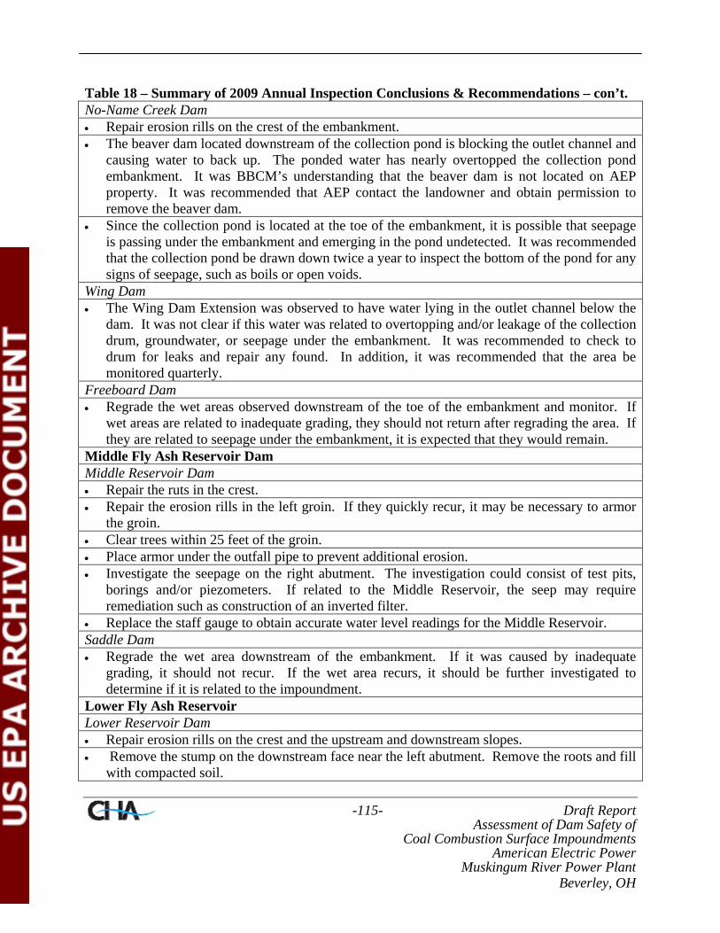
-115- Draft Report Assessment of Dam Safety of
Coal Combustion Surface Impoundments American Electric Power
Muskingum River Power Plant Beverley, OH
Table 18 – Summary of 2009 Annual Inspection Conclusions & Recommendations – con’t. No-Name Creek Dam • Repair erosion rills on the crest of the embankment. • The beaver dam located downstream of the collection pond is blocking the outlet channel and
causing water to back up. The ponded water has nearly overtopped the collection pond embankment. It was BBCM’s understanding that the beaver dam is not located on AEP property. It was recommended that AEP contact the landowner and obtain permission to remove the beaver dam.
• Since the collection pond is located at the toe of the embankment, it is possible that seepage is passing under the embankment and emerging in the pond undetected. It was recommended that the collection pond be drawn down twice a year to inspect the bottom of the pond for any signs of seepage, such as boils or open voids.
Wing Dam • The Wing Dam Extension was observed to have water lying in the outlet channel below the
dam. It was not clear if this water was related to overtopping and/or leakage of the collection drum, groundwater, or seepage under the embankment. It was recommended to check to drum for leaks and repair any found. In addition, it was recommended that the area be monitored quarterly.
Freeboard Dam • Regrade the wet areas observed downstream of the toe of the embankment and monitor. If
wet areas are related to inadequate grading, they should not return after regrading the area. If they are related to seepage under the embankment, it is expected that they would remain.
Middle Fly Ash Reservoir Dam Middle Reservoir Dam • Repair the ruts in the crest. • Repair the erosion rills in the left groin. If they quickly recur, it may be necessary to armor
the groin. • Clear trees within 25 feet of the groin. • Place armor under the outfall pipe to prevent additional erosion. • Investigate the seepage on the right abutment. The investigation could consist of test pits,
borings and/or piezometers. If related to the Middle Reservoir, the seep may require remediation such as construction of an inverted filter.
• Replace the staff gauge to obtain accurate water level readings for the Middle Reservoir. Saddle Dam • Regrade the wet area downstream of the embankment. If it was caused by inadequate
grading, it should not recur. If the wet area recurs, it should be further investigated to determine if it is related to the impoundment.
Lower Fly Ash Reservoir Lower Reservoir Dam • Repair erosion rills on the crest and the upstream and downstream slopes. • Remove the stump on the downstream face near the left abutment. Remove the roots and fill
with compacted soil.

-116- Draft Report Assessment of Dam Safety of
Coal Combustion Surface Impoundments American Electric Power
Muskingum River Power Plant Beverley, OH
Table 18 – Summary of 2009 Annual Inspection Conclusions & Recommendations – con’t. Wastewater Pond • Add armoring under the inlet pipes to prevent erosion. • Monitor the concrete in the outfall structure for additional damage. • Repair corrosion damage on the steel of the outfall structure bridge. • Operate the valve on the outfall structure quarterly. • Remove trees and stumps on the downstream face of the embankment. Backfill with
compacted soil. • Investigate the seeps in the southwest corner of the pond, which may be related to the Lower
Reservoir or groundwater. If it is related to the Lower Reservoir, remediation measures may be necessary.
Units 1-4 Bottom Ash Pond • Repair erosion rills along the inboard slope of the embankment and along the northern side of
the pond. • Repair the rodent burrows. It was recommended to fill the burrows with bentonite slurry. If
the problem persists, fumigation and/or trapping may be necessary. • Remove woody and viney vegetation from the face of the embankment. • Remove stumps and roots on the outboard slope and backfill with compacted material. • Monitor the Muskingum River west bank for tree fall and slumps. It was recommended that
it may be beneficial to cut tress before they topple to prevent stream bank erosion. • Repair the slump along the Muskingum River west bank. This area may need armoring to
prevent stream bank erosion. • Monitor the lower area on the inboard face of the west embankment from which dredging
equipment accessed the impoundment. This area appears to have more erosion than other areas on the embankment.
Instrumentation • Add general stratigraphy to the well construction diagrams and identify the flow regime for
each piezometer. Plot the pheratic surfaces on a cross section of the dam. • Establish ‘action levels’ for instruments. It was recommended to establish two criteria for
action; change from previous reading and change from a baseline established for each instrument. Action levels recommended – Alert, Warning and Emergency Procedures.
• With the raising of the Upper Fly Ash Reservoir, evaluate and estimate changes in the instrument data. Compare future readings to the estimated values.
• It was recommended that it may be desirable to install vibrating wire piezometer in addition to the existing Casagrande style piezometers for a quicker response time and connection to a data logger.
• Inclinometers seem to have more pronounced deflections in the upper three to five feet. This may be due to shifting of the rip rap and/or thermal expansion of the casing.
• Evaluate the operating procedure for field collection to minimize errors on collecting and recording data.
• Determine the accuracy of measurements for all data collected.

-117- Draft Report Assessment of Dam Safety of
Coal Combustion Surface Impoundments American Electric Power
Muskingum River Power Plant Beverley, OH
Table 18 – Summary of 2009 Annual Inspection Conclusions & Recommendations – con’t. • In general, the inclinometers show a gradual deformation starting with the first reading above
the bottom of the instrument. This may be due to an error in reading the instrument and should be evaluated. In addition, the subsurface stratigraphy should be included with the Deformation Review.
• Survey monuments on the Mill Stone Creek Dam, No-Name Creek Dam, and Wing Dam all show movement trending in the northern direction with minor movement in the east direction. If the pressure of the reservoir fill is causing movement, it would be expected that the embankment would move perpendicular to the centerline of the dam, in the northeast direction. This may suggest it is an error in the reading, although both the cumulative and differential movement are relatively small. It may be beneficial to install several survey monuments outside the embankments and obtain readings from these fixed monuments as a check against error.
• It was recommended that it may be beneficial to install piezometers in the abutments downstream of the embankments to determine the groundwater elevation, in particular along the right abutment of the Mill Stone Creek Dam.
3.5.2 State of Ohio Inspections
Ohio Revised Code Section 1521.062 states that the owners of dams must monitor, maintain, and
operate their dams safely. The owner is to maintain a safe structure and appurtenances through
inspection, maintenance, and operation.
Representatives of the ODNR Dam Safety Program inspected the Middle Fly Ash Reservoir,
Lower Fly Ash Reservoir and Units 1-4 Bottom Ash Pond structures on November 3, 2008.
Dam Safety Inspection Reports were provided to AEP following the department’s site visit. A
Dam Safety Inspection of the Upper Fly Ash Reservoir dams and dikes was not performed on
this date as the dams and dikes are currently being raised. As this is an on-going project ONDR
is making routine site visits to observe construction activities.
The ONDR Dam Safety Inspection Reports included required remedial measures based on
observations made during the inspections, calculations performed and requirements of the Ohio
Administrative Code. A summary of the required remedial measures outlined in the November
2008 inspection reports is provided in Table 19. For Engineering Repairs and Investigations the

-118- Draft Report Assessment of Dam Safety of
Coal Combustion Surface Impoundments American Electric Power
Muskingum River Power Plant Beverley, OH
dam owner must retain the services of a professional engineer to address the plans, specification,
investigative reports, and other supporting documentation. The owner is required to complete
the items within five (5) years. Owner repairs may be performed by the dam owner or by a hired
contractor.
Table 19 – Summary of Required Remedial Measures Middle Fly Ash Reservoir Dam (ODNR File Number: 9415-008) Engineering Repairs and Investigations 1. The spillway conduit system must perform properly without endangering the safety of the
dam. Investigate the condition of the pipe joints in the principal spillway outlet pipe and, as necessary, prepare plans and specifications for the repair of the pipe joints. Regardless of the results of the investigation, the condition of the entire spillway conduit system, must be monitored yearly.
Owner Repairs 1. Remove trees and brush from the downstream slope and within 10 feet from the downstream
groins. 2. Repair the erosion gully on the upstream slope. 3. Seed the sparse areas on the upstream slope to establish a proper grass cover. Remove the
tall vegetation at the principal spillway inlet. 4. Repair the staff gauge next to the principal spillway inlet so that elevations can be
determined. 5. Regrade the seepage area in the right abutment to prevent standing water. Install a weir so
that flow can be easily measured. 6. Repair the low areas on the crest. Following repairs, the alignment of the crest must be
monitored for recurrence of the low areas. Additional Items Owner Must Address 1. Review and, as necessary, update the operations, maintenance, and inspection manual and the
emergency action plan. 2. Monitor the wet area on the downstream right abutment and the saddle dam drain monthly
for any signs of increased flow, muddy flow, or instability on or adjacent to the embankment. 3. Monitor piezometer in the dam for any rise or fall of the pheratic surface within the
embankment. Perform any needed maintenance to maintain a working piezometer. 4. Monitor the condition of the concrete spillway riser yearly for further deterioration. Lower Fly Ash Reservoir Dam (ODNR File Number: 9415-007) Engineering Repairs and Investigations None noted. Owner Repairs Reapply joint sealant in the concrete spillway discharge pipe. Remove the saplings and brush from the downstream slope. Seed all disturbed areas to establish a proper grass cover or rip rap cover.

-119- Draft Report Assessment of Dam Safety of
Coal Combustion Surface Impoundments American Electric Power
Muskingum River Power Plant Beverley, OH
Table 19 – Summary of Required Remedial Measures – con’t. The embankment drain system must function properly. Clear the vegetation from around the outlet of the toe drain pipe and seepage area in the left downstream toe area. Mow all vegetation on the embankment at least twice per year. Repair rodent burrows on the embankment. Repair the erosion gully on the downstream slope. Repair the staff gauge next to the principal spillway inlet so that elevations can be determined. The access walkway to the principal spillway must be maintained to allow for maintenance and inspection of the spillway riser structure. The metal walkway must be painted to prevent rust and corrosion. Additional Items Owner Must Address Review and, as necessary, update the operations, maintenance, and inspection manual and the emergency action plan. Monitor the condition of the discharge pipe outlet yearly for further deterioration of the interior bituminous coating. Monitor the piezometer in the dam for any rise or fall of the pheratic surface within the embankment. Perform any needed maintenance to maintain a working piezometer. The embankment drain system must function properly. Monitor flow exiting the toe drain outlet and the seepage on the downstream toe and left abutment quarterly for any sign of increased flow, muddy flow, or instability on or adjacent to the embankment. Monitor the wave erosion scarp on the upstream slope yearly for additional erosion, sloughing, or slope instability. Units 1-4 Bottom Ash Pond Dam (ONDR File Number: 9415-001) Engineering Repairs and Investigations None noted. Owner Repairs Remove trees and brush from the exterior embankment. While mowing extents on the portion of the embankment adjacent to the Muskingum River appeared to be appropriate, any mature trees located on this portion of the embankment must be removed as they age or die. Establish a healthy grass cover on the embankment adjacent to the Muskingum River through routine mowing. Mowing frequency on grassed portions of the embankment must be increased to at least twice a year. If grass does not become established on portions of the embankment following an increased mowing schedule, seeding, spraying or other owner maintenance will be required to remove all brush and saplings. Update the EAP to include specific information on the Unit 1-4 Bottom Ash Pond. Update the OMI to include structure and operation for this pond.
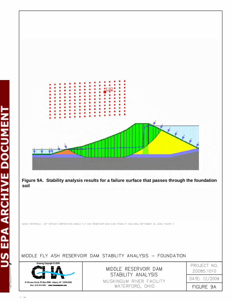
Figure 9A. Stability analysis results for a failure surface that passes through the foundationsoil
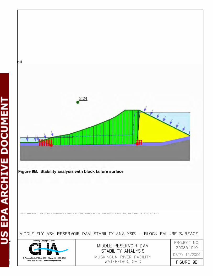
oil
Figure 9B. Stability analysis with block failure surface

Figure 9C. Stability analysis results for the top portion of the slope with a shallow failuresurface
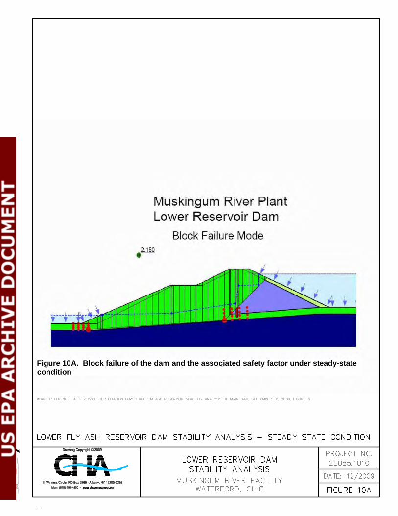
Figure 10A. Block failure of the dam and the associated safety factor under steady-statecondition

Figure 10B. Stability analysis results under steady-state condition using a seep failuresurface
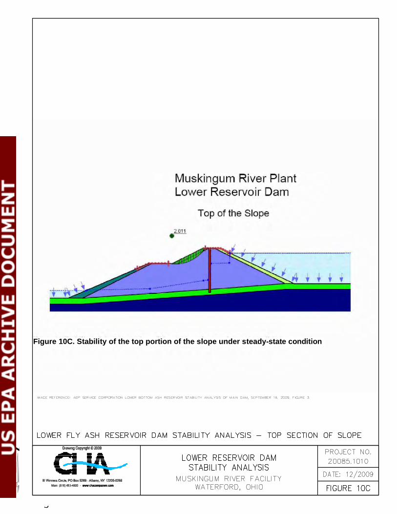
Figure 10C. Stability of the top portion of the slope under steady-state condition

Figure 10D. Stability of the lower portion of the slope under steady-state condition


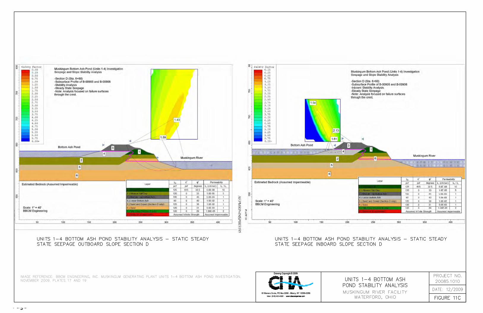

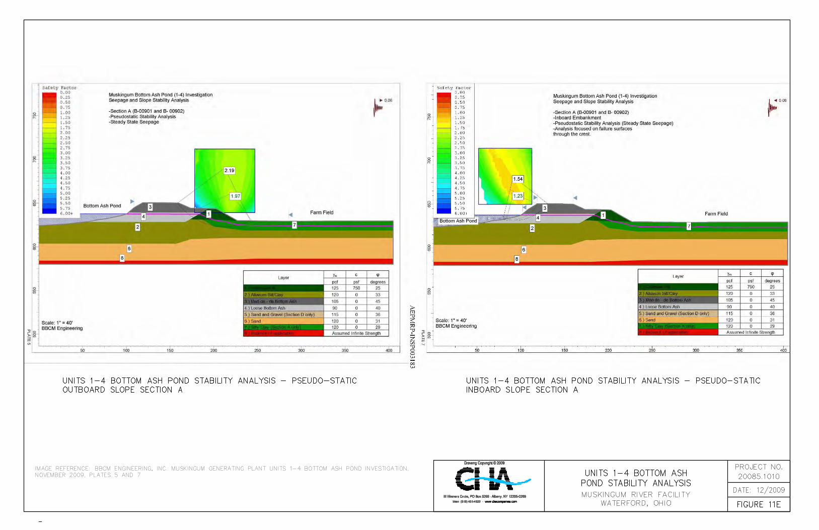


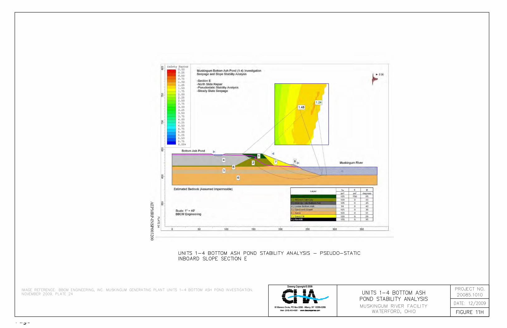

-135- Draft Report Assessment of Dam Safety of
Coal Combustion Surface Impoundments American Electric Power
Muskingum River Power Plant Beverley, OH
4.0 CONCLUSIONS/RECOMMENDATIONS
4.1 Acknowledgement of Management Unit Condition
4.1.1 Acknowledgement of the Upper Fly Ash Reservoir Dams Conditions
I acknowledge that the Upper Fly Ash Reservoir Mill Stone Creek, No-Name Creek, Wing,
Spillway and Freeboard Dams, referenced herein, were personally inspected by me and were
found to be in the following condition: Satisfactory. This indicates that there is no existing or
potential safety deficiencies recognized. Acceptable performance is expected under all applicable
loading conditions (static, hydrologic, seismic) and that minor maintenance items may be
required.
4.1.2 Acknowledgement of the Middle and Lower Fly Ash Reservoir Dams Conditions
I acknowledge that the Middle Fly Ash Reservoir Dam, the Middle Fly Ash Reservoir Spillway
Dam and the Lower Fly Ash Dam, referenced herein, were personally inspected by me and were
found to be in the following condition: Fair. This indicates acceptable performance is expected
under required loading conditions in accordance with applicable safety regulatory criteria;
however some additional analyses should be performed and documented to verify that these
criteria are met.
4.1.2 Acknowledgement of the Units 1-4 Bottom Ash Pond Dike Conditions
I acknowledge that the Units 1-4 Bottom Ash Pond dikes, referenced herein, were personally
inspected by me and were found to be in the following condition: Poor. A management unit
found to be in poor condition is defined as one in which a safety deficiency is recognized for any
required loading condition (static, hydrologic, seismic) in accordance with the applicable dam

-136- Draft Report Assessment of Dam Safety of
Coal Combustion Surface Impoundments American Electric Power
Muskingum River Power Plant Beverley, OH
safety regulatory criteria. Remedial action is necessary. Poor also applies when further critical
studies or investigations are needed to identify any potential dam safety deficiencies.
In the sections below, CHA presents recommendations for maintenance and further studies to
bring these facilities into satisfactory condition. CHA also recommends that the
recommendations presented in BBCM’s March 12, 2009 inspection report and ODNR’s
November 3, 2008 Dam Safety Inspection Reports be addressed.
4.2 Monitoring of Seeps
Seeps were observed in the following locations during CHA’s site assessment and by ODNR,
BBCM and AEP Service Corporation:
• Mill Stone Creek Dam – isolated seep in the natural hillside at the right (southeast)
abutment outside of the rock lined ditch (Section 2.2.1);
• Mill Stone Creek Dam – downstream face of the collection pond embankment (Section
3.5.1);
• No-Name Creek Dam – adjacent to the rock outcrop above the right (southeast) abutment
ditch (Section 2.2.2) and BBCM noted that it is possible that seepage is passing under the
embankment and emerging in the pond undetected (Section 3.5.1);
• Lower Fly Ash Dam (cement-bentonite-fly ash slurry wall installed, Section 1.4.4 and
Section 2.4.1);
It is that AEP develop a procedure to observe these areas on a routine basis (i.e. monthly) and
document these observations in written reports that are kept on file at the facility. The
procedure should outline steps that should be taken in the event that increased flow, muddy
flow, or instability on or adjacent to an area of seepage is observed.

-137- Draft Report Assessment of Dam Safety of
Coal Combustion Surface Impoundments American Electric Power
Muskingum River Power Plant Beverley, OH
4.3 Repair of Erosion
Areas of erosion were observed in the following locations during CHA’s site assessment and by
ODNR, BBCM and AEP Service Corporation:
• Wing Dam – upstream embankment slope where compacted ash was exposed (Section
2.2.3);
• Freeboard Dam – downstream embankment slope, particularly in the locations were ash
is exposed and upstream embankment slope (Section 2.2.5);
• No-Name Creek Dam – on the crest of the dam (Section 3.5.1);
• Middle Fly Ash Dam – downstream embankment slope in the unarmored surface (Section
2.3.1);
• Emergency Spillway Dam – observed in the crest surface adjacent to the upstream slope
(Section 2.3.2);
• Lower Fly Ash Reservoir Dam - beaching erosion on the upstream slope and downstream
slope (Section 2.4.1);
• Units 1-4 Bottom Ash Pond – exterior slope (Section 2.5.1) and interior slopes (Section
3.5.1);
These areas typically had intermittent erosion rills, likely exacerbated when grading activities
pushed loose material to the crest edge and sheet flow became concentrated during rain events.
These erosion rills should be filled in with compacted material and stabilized (seeded and
mulched).
Surface sloughs were noted in over-steepened areas (i.e. Units 1-4 Bottom Ash Pond interior
sloped). These areas should be regarded to a flatter slope where possible and reseeded or
armored with a stone material. Monitoring of these areas should be conducted to check for any
continued movement.

-138- Draft Report Assessment of Dam Safety of
Coal Combustion Surface Impoundments American Electric Power
Muskingum River Power Plant Beverley, OH
4.4 Repair of Rodent Burrows
Evidence of animal burrows was observed in the following locations during CHA’s site
assessment and by ODNR, BBCM and AEP Service Corporation:
• Mill Stone Creek Dam – right (southeast) abutment in the natural hillside (Section 2.2.1);
• Lower Fly Ash Reservoir Dam – observed in the portion of the embankment not armored
with rip rap (Section 2.4.1);
• Units 1-4 Bottom Ash Pond – exterior slope (Section 2.5.1 and Section 3.5.1);
CHA recommends that AEP keep notes of areas disturbed by animal activity, trapping of the
animals, and repair to the areas. BBCM recommended that burrow be filled with bentonite
slurry.
4.5 Additional Stability Analyses – Upper Fly Ash Reservoir
CHA recommends that rapid drawdown analyses be performed for the current conditions and for
the final raised embankment condition at the Upper Fly Ash Reservoir. While CHA understand
that rapid drawdown via pumping or other discharge methods may be undesirable for a waste
disposal impoundment, CHA suggests that in the event of an emergency at the facility, rapid
drawdown may be more desirable to reduce hydrostatic pressures on the dam, thereby preventing
a more catastrophic collapse. There have also been documented case histories where other types
of failure (such as a gate failure) have resulted in rapid drawdown conditions developing which
have led to a domino effect and made the situation worse. For these reasons, CHA recommends
that a rapid drawdown analysis be performed.

-139- Draft Report Assessment of Dam Safety of
Coal Combustion Surface Impoundments American Electric Power
Muskingum River Power Plant Beverley, OH
4.6 Additional Stability Analyses – Middle Fly Ash Reservoir
CHA recommends that an updated stability analysis be performed for the Middle Fly Ash
Reservoir Dam using the data obtained during the recent subsurface investigation. The analyses
should reflect the current pheratic surface in the embankment. Soil properties for to be used in
the analysis should be reflective of the material encountered in the three borings advanced at the
structure in September 2009 as well as historical data available for the structure. Loading
conditions that should be considered in the analyses should include: steady state conditions at
present pool or maximum storage pool elevation, rapid drawdown conditions from present pool
elevation, maximum surcharge pool (flood) condition, seismic conditions from present pool
elevation and liquefaction.
4.7 Additional Stability Analyses – Lower Fly Ash Reservoir
CHA recommends that an updated stability analysis be performed for the Lower Fly Ash
Reservoir Dam using the data obtained during the recent subsurface investigation. The analyses
should reflect the current pheratic surface in the embankment. Soil properties for to be used in
the analysis should be reflective of the material encountered in the four borings advanced at the
structure in November 2009 as well as historical data available for the structure. Loading
conditions that should be considered in the analyses should include: steady state conditions at
present pool or maximum storage pool elevation, rapid drawdown conditions from present pool
elevation, maximum surcharge pool (flood) condition, seismic conditions from present pool
elevation and liquefaction.
4.8 Stability of the Units 1-4 Bottom Ash Pond East Dike
The stability analyses conducted by BBCM (outlined in Section 3.3.4) indicated that at four cross
sections examined through the active pond east embankments the factors of safety relative to
those recommended by the USACOE were found to be inadequate. The principal reason for this
-140- Draft Report Assessment of Dam Safety of
Coal Combustion Surface Impoundments American Electric Power
Muskingum River Power Plant Beverley, OH
is unsatisfactory condition is the proximity of the east embankment to the eroding Muskingum
Riverbank. BBCM suggested that a revetment would significantly increase the factor of safety
against failure of the east embankment. Factors of safety were computed for a section of the
northern slope which was repaired in such a manner. The factors of safety met the minimum
recommended factors of safety provided by the USACOS (outlined in Table 6). CHA
recommends that AEP make similar improvements to the east dike where inadequate factors of
safety were indicated to stabilize the embankment.
4.9 Trees and Stumps
Trees were noted on the in the following locations:
• Units 1-4 Bottom Ash Pond east dike at the lower portion of the slope. Some trees
observed were on the order of 12 inches in diameter (Section 2.5.1 and 3.5.2).
• Near bottom of the downstream slope and the groins of the Middle Fly Ash Dam (Section
3.5.1).
• At the Wastewater Pond (Section 3.5.1).
Tree roots can allow for seepage of the retained water through the dikes, which could lead to
internal erosion such as is the concern in an impoundment with free water. Internal erosion
would weaken the dike, and could result in a slope failure.
Additionally, the uprooting of trees during storms can create large voids in the embankment that
are then susceptible to erosion. Considering the progressive erosion that could occur during a
storm which blows the tree over during heavy rains (i.e., hurricane type storm systems)
progressive erosion could potentially result in enough loss of soil from the dike to create an
unstable situation, which if failure occurs could result in a release of ash. CHA recommends the
removal of tree, brush and roots at the locations notes above. Large trees and roots should be
removed and the areas repaired with the direction of a qualified engineer. Once tress and roots
-141- Draft Report Assessment of Dam Safety of
Coal Combustion Surface Impoundments American Electric Power
Muskingum River Power Plant Beverley, OH
are removed, proper, short vegetation should be established to allow for more thorough
observation or changing conditions that may require routine maintenance before they become
larger problems.
4.10 Establishing Vegetation
CHA recommends that AEP seed the sparse areas on the upstream slope of the Middle Fly Ash
Reservoir to establish a proper grass cover. A healthy grass cover should also be established on
the Units 1-4 Bottom Ash pond east embankment adjacent to the Muskingum River through
routine mowing. Mowing frequency on grassed portions of the embankment should be
conducted at least twice a year. If grass does not become established on portions of the
embankment following an increased mowing schedule, seeding, spraying or other maintenance
may be necessary.
4.11 Monitoring of Middle Fly Ash Reservoir Principal Spillway
As noted by ODNR, a spillway conduit system must perform properly without endangering the
safety of the dam. The condition of the pipe joints in the principal spillway outlet pipe should be
investigated and, as necessary, plans and specifications prepared for the repair of the pipe joints.
Regardless of the results of the investigation, the condition of the entire spillway conduit system,
must be monitored yearly.
4.12 Repair of Damaged Instrumentation
The staff gauge to obtain accurate water level readings for the Middle Fly Ash Reservoir should
be replaced. The staff gauge at the Lower Fly Ash Reservoir next to the principal spillway inlet
should be repaired so that elevations can be determined.

-142- Draft Report Assessment of Dam Safety of
Coal Combustion Surface Impoundments American Electric Power
Muskingum River Power Plant Beverley, OH
4.13 Routine Observations, Data Collection and Documentation
CHA was not provided with documentation that facility personnel perform routine observations
of the dams and dikes or record data from monitoring instrumentation (piezometers, surface
monuments, inclinometers). CHA recommend that AEP update their OMI for the structures to
include the recommendation from BBCM, ODNR and CHA. Tasks that should be included in
the OMI updates are:
• Establish ‘action levels’ for instruments. It was recommended to establish two criteria
for action; change from previous reading and change from a baseline established for each
instrument. Action levels recommended – Alert, Warning and Emergency Procedures.
• A procedure for monitoring repairs (such as the low point on the crest of the Middle Fly
Ash Reservoir Dam) for recurrence
• Monitor piezometers in the dam for any rise or fall of the pheratic surface within the
embankments on a routine basis.
• Document monitoring of the condition of the Middle Fly Ash Reservoir concrete spillway
riser yearly for further deterioration.
• Document the monitor the condition of the Lower Fly Ash Reservoir discharge pipe
outlet yearly for further deterioration of the interior bituminous coating.
• Record observations of flow exiting the toe drain outlet and the seepage quarterly. Have
procedures in place should there be any sign of increased flow, muddy flow, or instability
on or adjacent to the embankment.

-143- Draft Report Assessment of Dam Safety of
Coal Combustion Surface Impoundments American Electric Power
Muskingum River Power Plant Beverley, OH
5.0 CLOSING
The information presented in this report is based on visual field observations, review of reports
by others and this limited knowledge of the history of the Muskingum River Power Plant surface
impoundments. The recommendations presented are based, in part, on project information
available at the time of this report. No other warranty, expressed or implied is made. Should
additional information or changes in field conditions occur, the conclusions and
recommendations provided in this report should be re-evaluated by an experienced engineer.

Draft Report Assessment of Dam Safety of
Coal Combustion Surface Impoundments American Electric Power
Muskingum River Power Plant Beverley, OH
APPENDIX A
Completed EPA Coal Combustion Dam Inspection Checklist Forms
&
Completed EPA Coal Combustion Waste (CCW) Impoundment Inspection Forms

Site Name: Date:Unit Name: Operator's Name: Unit I.D.: Hazard Potential Classification: High Significant Low
Inspector's Name:
Coal Combustion Dam Inspection Checklist FormUS EnvironmentalProtection Agency
Check the appropriate box below. Provide comments when appropriate. If not applicable or not available, record "N/A". Any unusual conditions or construction practices that should be noted in the comments section. For large diked embankments, separate checklists may be used for different embankment areas. If separate forms are used, identify approximate area that the form applies to in comments.
Yes No Yes No
1. Frequency of Company's Dam Inspections? 18. Sloughing or bulging on slopes?
2. Pool elevation (operator records)? 19. Major erosion or slope deterioration?
3. Decant inlet elevation (operator records)? 20. Decant Pipes:
4. Open channel spillway elevation (operator records)? Is water entering inlet, but not exiting outlet?
5. Lowest dam crest elevation (operator records)? Is water exiting outlet, but not entering inlet?
6. If instrumentation is present, are readings recorded (operator records)? Is water exiting outlet flowing clear?
7. Is the embankment currently under construction? 21. Seepage (specify location, if seepage carries fines, and approximate seepage rate below):
8. Foundation preparation (remove vegetation,stumps, topsoil in area where embankment fill will be placed)? From underdrain?
9. Trees growing on embankment? (If so, indicate largest diameter below) At isolated points on embankment slopes?
10. Cracks or scarps on crest? At natural hillside in the embankment area?
11. Is there significant settlement along the crest? Over widespread areas?
12. Are decant trashracks clear and in place? From downstream foundation area?
13. Depressions or sinkholes in tailings surface orwhirlpool in the pool area? "Boils" beneath stream or ponded water?
14. Clogged spillways, groin or diversion ditches? Around the outside of the decant pipe?
15. Are spillway or ditch linings deteriorated? 22. Surface movements in valley bottom or on hillside?
16. Are outlets of decant or underdrains blocked? 23. Water against downstream toe?
17. Cracks or scarps on slopes? 24. Were Photos taken during the dam inspection?
Major adverse changes in these items could cause instability and should be reported forfurther evaluation. Adverse conditions noted in these items should normally be described (extent, location, volume, etc.) in the space below and on the back of this sheet.
Inspection Issue # Comments
EPA FORM -XXXX
Muskingum River Power Plant October 21, 2009
Muskingum River Upper Fly Ash Dam American Electric Power
OH00989
Malcolm D. Hargraves P.E. /Rebecca Filkins
quarterly
826
826
n/a see
approx. 837 see
x x
x
x
note
note
x
x
x
x
x
x
see
xx
x
x
xx
x
x
x
x
x
x
x
note
x
N/A = Not Applicable/Available.
5, 7, 8 The upper fly dam impoundment comprises 5 dikes that are currently being raised to a final crest elevation
at 842. Four of the five dikes previously existed; the new dike (Freeboard Dam) was nearing completion at the
stream side.
time of the site visit. CHA understands that all of the dikes have been seated on bed rock.
15, 16, 20 The invert of the outlet pipe is submerged on the upstream side and partially submerged on the down-
18 Occasional erosion rills noted on working surface in ash and soil material.
21 Clear seepage was noted in underdrains and hillside at the Mill Stone, No Name, and Wing Dam dikes.

U. S. Environmental Protection Agency
Coal Combustion Waste (CCW)Impoundment Inspection
Impoundment NPDES Permit # _____________________ INSPECTOR______________________Date ____________________________________
Impoundment Name ________________________________________________________Impoundment Company ____________________________________________________EPA Region ___________________State Agency (Field Office) Addresss __________________________________________
__________________________________________Name of Impoundment _____________________________________________________(Report each impoundment on a separate form under the same Impoundment NPDES Permit number)
New ________ Update _________
Yes NoIs impoundment currently under construction? ______ ______Is water or ccw currently being pumped into the impoundment? ______ ______
IMPOUNDMENT FUNCTION: _____________________________________________
Nearest Downstream Town : Name ____________________________________Distance from the impoundment __________________________ ImpoundmentLocation: Longitude ______ Degrees ______ Minutes ______ Seconds Latitude ______ Degrees ______ Minutes ______ Seconds
State _________ County ___________________________
Does a state agency regulate this impoundment? YES ______ NO ______
If So Which State Agency?___________________________________________
EPA Form XXXX-XXX, Jan 09 1
OH0006149 Hargraves/Filkins
October 21, 2009
Muskingum River Upper Fly Ash Dam
American Electric Power5
Ohio EPA Southeast District Office2195 Front Street; Logan, Ohio 43138-8687
Muskingum River Upper Fly Ash Dam
x
x
x
Fly Ash
Beverly, Ohio3 miles
81 41 6
39 34 30Ohio Washington
x
ODNR - Division of Water

HAZARD POTENTIAL (In the event the impoundment should fail, the following would occur):
______ LESS THAN LOW HAZARD POTENTIAL: Failure or misoperation of the dam results in no probable loss of human life or economic or environmental losses.
______ LOW HAZARD POTENTIAL: Dams assigned the low hazard potential classification are those where failure or misoperation results in no probable loss of human life and low economic and/or environmental losses. Losses are principally limited to the owner’s property.
______ SIGNIFICANT HAZARD POTENTIAL: Dams assigned the significant hazard potential classification are those dams where failure or misoperation results in no probable loss of human life but can cause economic loss, environmental damage, disruption of lifeline facilities, or can impact other concerns. Significant hazard potential classification dams are often located in predominantly rural or agricultural areas but could be located in areas with population and significant infrastructure.
______ HIGH HAZARD POTENTIAL: Dams assigned the high hazard potential classification are those where failure or misoperation will probably cause loss of human life.
DESCRIBE REASONING FOR HAZARD RATING CHOSEN: _______________________________________________________________________________________________________________________________________________________________________________________________________________________________________________________________________________________________________________________________________________________________________________________________________________________________________________________________________________________________________________________________________________________________________________________________________________________________________________________________________________________________________________________________________________________________________________________________________________________________________________________________________________________________________________________________________________________________________________________________________________
EPA Form XXXX-XXX, Jan 09 2
x
In the event of a failure under full pool the Muskingum River Plant facilities, GlobeMetallurgical Plant facilities, and County route 32 would likely be affected. Eventually thebreach wave would likely impact the Muskingum River.
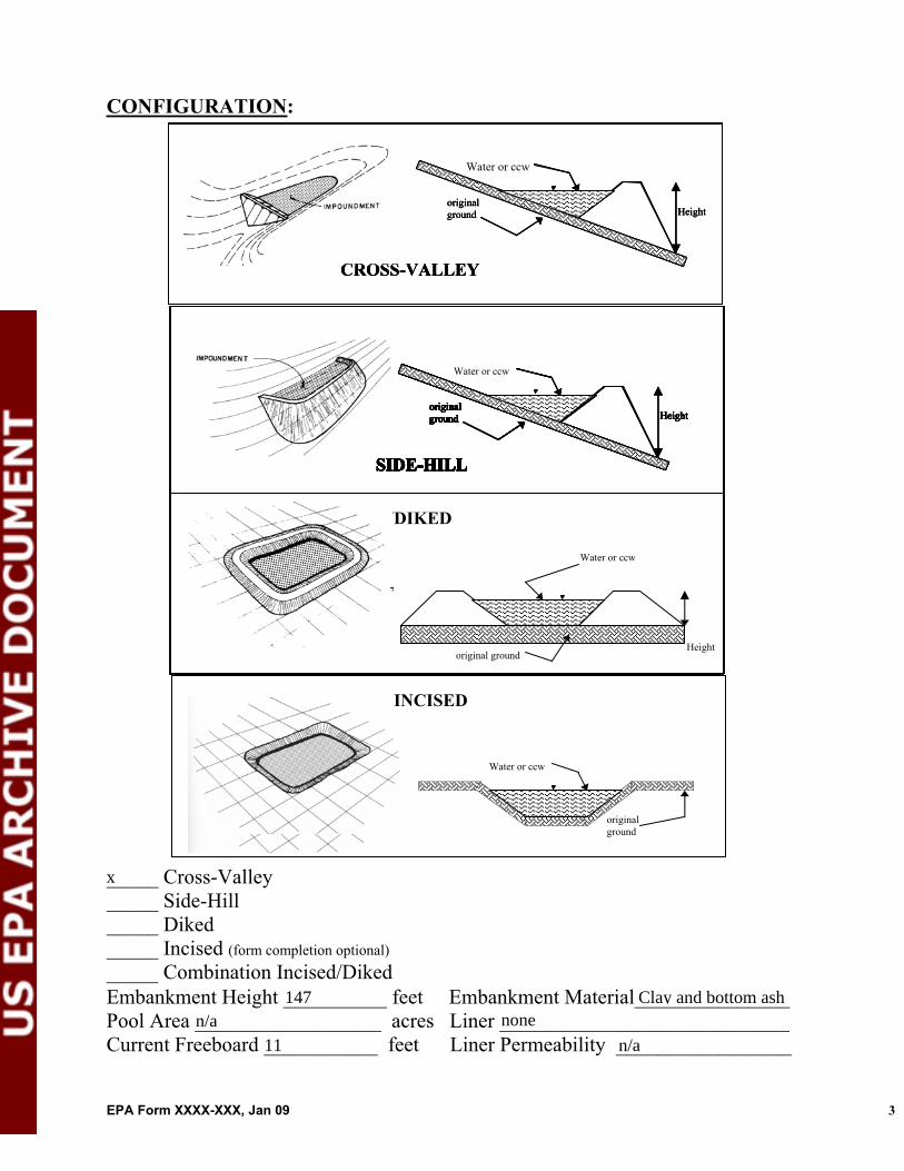
CONFIGURATION:
Height original ground
CROSS-VALLEY
Height original ground
SIDE-HILL
Water or ccw
DIKED
original ground Height
Height original ground
CROSS-VALLEY
Water or ccw
original ground
SIDE-HILL
Height original ground
CROSS-VALLEY
original ground
SIDE-HILL
original ground
SIDE-HILL
original ground
SIDE-HILL
original original ground ground
SIDE-HILLSIDE-HILL
original ground
SIDE-HILLSIDE-HILL
original ground Height
SIDE-HILLSIDE-HILLSIDE-HILL
Height Height original ground original ground Height
SIDE-HILL
original ground Height
SIDE-HILL
Water or ccw
original ground Height
SIDE-HILL
INCISED
Water or ccw
original ground
_____ Cross-Valley _____ Side-Hill _____ Diked _____ Incised (form completion optional)_____ Combination Incised/Diked Embankment Height __________ feet Embankment Material_______________Pool Area __________________ acres Liner ____________________________ Current Freeboard ___________ feet Liner Permeability _________________
EPA Form XXXX-XXX, Jan 09 3
x
147 Clay and bottom ashn/a none
11 n/a

TYPE OF OUTLET (Mark all that apply)
TRAPEZOIDAL
Avg Depth
Bottom Width
Depth
TRIANGULAR_____ Open Channel Spillway_____ Trapezoidal Top Width Top Width
_____ Triangular
RECTANGULAR IRREGULAR
Depth _____ Rectangular _____ Irregular
_____ depth _____ bottom (or average) width
Width
Depth
Average Width
_____ top width
_____ Outlet
_____ inside diameter
Material Inside Diameter
_____ corrugated metal _____ welded steel _____ concrete _____ plastic (hdpe, pvc, etc.) _____ other (specify) ____________________
Is water flowing through the outlet? YES _______ NO _______
_____ No Outlet
_____ Other Type of Outlet (specify) ________________________________
The Impoundment was Designed By ______________________________________________________________________________________________________
EPA Form XXXX-XXX, Jan 09 4
n/a
x
24
x
x
Harza Engineering Co.; AEP

Has there ever been a failure at this site? YES __________ NO ___________
If So When? ___________________________
If So Please Describe : _____________________________________________________________________________________________________________________________________________________________________________________________________________________________________________________________________________________________________________________________________________________________________________________________________________________________________________________________________________________________________________________________________________________________________________________________________________________________________________________________________________________________________________________________________________________________________________________________________________________________________________________________________________________________________________________________________________________________________________________________________________________________________________________________________________________________________________________________________________________________________________________________________________________________________________________________________________________________________________________________________________________________________________________________________________________________________________________________________________________________________________________________________________________________________________________________________________________________________________________________________________________________________________________________________________________________________________________________________________________________________________________________________________________________________________________________________________________________________________________________________________________________________________________________________________________________________________________________________________________________________________________________________________________________________________
EPA Form XXXX-XXX, Jan 09 5
x
n/a

Has there ever been significant seepages at this site? YES _______ NO _______
If So When? ___________________________
IF So Please Describe: _______________________________________________________________________________________________________________________________________________________________________________________________________________________________________________________________________________________________________________________________________________________________________________________________________________________________________________________________________________________________________________________________________________________________________________________________________________________________________________________________________________________________________________________________________________________________________________________________________________________________________________________________________________________________________________________________________________________________________________________________________________________________________________________________________________________________________________________________________________________________________________________________________________________________________________________________________________________________________________________________________________________________________________________________________________________________________________________________________________________________________________________________________________________________________________________________________________________________________________________________________________________________________________________________________________________________________________________________________________________________________________________________________________________________________________________________________________________________________________________________________________________________________________________________________________________________________________________________________________________________________________________________________________________________________________
EPA Form XXXX-XXX, Jan 09 6
x

Has there ever been any measures undertaken to monitor/lowerPhreatic water table levels based on past seepages or breaches at this site? YES ________NO ________
If so, which method (e.g., piezometers, gw pumping,...)? ____________________
If so Please Describe : ____________________________________________________________________________________________________________________________________________________________________________________________________________________________________________________________________________________________________________________________________________________________________________________________________________________________________________________________________________________________________________________________________________________________________________________________________________________________________________________________________________________________________________________________________________________________________________________________________________________________________________________________________________________________________________________________________________________________________________________________________________________________________________________________________________________________________________________________________________________________________________________________________________________________________________________________________________________________________________________________________________________________________________________________________________________________________________________________________________________________________________________________________________________________________________________________________________________________________________________________________________________________________________________________________________________________________________________________________________________________________________________________________________________________________________________________________________________________________________________________________________________________________________________________________________________________________________________________________________________________________________________________________________________________________________
EPA Form XXXX-XXX, Jan 09 7
x

Site Name: Date:Unit Name: Operator's Name: Unit I.D.: Hazard Potential Classification: High Significant Low
Inspector's Name:
Coal Combustion Dam Inspection Checklist FormUS EnvironmentalProtection Agency
Check the appropriate box below. Provide comments when appropriate. If not applicable or not available, record "N/A". Any unusual conditions or construction practices that should be noted in the comments section. For large diked embankments, separate checklists may be used for different embankment areas. If separate forms are used, identify approximate area that the form applies to in comments.
Yes No Yes No
1. Frequency of Company's Dam Inspections? 18. Sloughing or bulging on slopes?
2. Pool elevation (operator records)? 19. Major erosion or slope deterioration?
3. Decant inlet elevation (operator records)? 20. Decant Pipes:
4. Open channel spillway elevation (operator records)? Is water entering inlet, but not exiting outlet?
5. Lowest dam crest elevation (operator records)? Is water exiting outlet, but not entering inlet?
6. If instrumentation is present, are readings recorded (operator records)? Is water exiting outlet flowing clear?
7. Is the embankment currently under construction? 21. Seepage (specify location, if seepage carries fines, and approximate seepage rate below):
8. Foundation preparation (remove vegetation,stumps, topsoil in area where embankment fill will be placed)? From underdrain?
9. Trees growing on embankment? (If so, indicate largest diameter below) At isolated points on embankment slopes?
10. Cracks or scarps on crest? At natural hillside in the embankment area?
11. Is there significant settlement along the crest? Over widespread areas?
12. Are decant trashracks clear and in place? From downstream foundation area?
13. Depressions or sinkholes in tailings surface orwhirlpool in the pool area? "Boils" beneath stream or ponded water?
14. Clogged spillways, groin or diversion ditches? Around the outside of the decant pipe?
15. Are spillway or ditch linings deteriorated? 22. Surface movements in valley bottom or on hillside?
16. Are outlets of decant or underdrains blocked? 23. Water against downstream toe?
17. Cracks or scarps on slopes? 24. Were Photos taken during the dam inspection?
Major adverse changes in these items could cause instability and should be reported forfurther evaluation. Adverse conditions noted in these items should normally be described (extent, location, volume, etc.) in the space below and on the back of this sheet.
Inspection Issue # Comments
EPA FORM -XXXX
Muskingum River Power Plant October 21, 2009
Muskingum River Middle Fly Ash Dam American Electric Power
OH00972
Malcolm D. Hargraves P.E. /Rebecca Filkins
quarterly
794.8
794.8
798
800
x x
x
x
x
x
n/a
x
x
x
x
x
x
xx
x
x
xx
x
x
x
x
x
x
x
x
N/A = Not Applicable/Not Available.
4 Elevation of open channel emergency spillway has been estimated.
12 Inclined spillway has a floating skimmer.
21 Clear seepage noted from hillside drain at right abutment contact (iron precipitate observed).
19 Isolated minor erosion rills noted on downstream bottom ash slope surface (most likely initiated by recent
grading operations or facility equipment activity.
23 Water against downstream toe (rip rap protected) is from lower fly ash reservoir.

U. S. Environmental Protection Agency
Coal Combustion Waste (CCW)Impoundment Inspection
Impoundment NPDES Permit # _____________________ INSPECTOR______________________Date ____________________________________
Impoundment Name ________________________________________________________Impoundment Company ____________________________________________________EPA Region ___________________State Agency (Field Office) Addresss __________________________________________
__________________________________________Name of Impoundment _____________________________________________________(Report each impoundment on a separate form under the same Impoundment NPDES Permit number)
New ________ Update _________
Yes NoIs impoundment currently under construction? ______ ______Is water or ccw currently being pumped into the impoundment? ______ ______
IMPOUNDMENT FUNCTION: _____________________________________________
Nearest Downstream Town : Name ____________________________________Distance from the impoundment __________________________ ImpoundmentLocation: Longitude ______ Degrees ______ Minutes ______ Seconds Latitude ______ Degrees ______ Minutes ______ Seconds
State _________ County ___________________________
Does a state agency regulate this impoundment? YES ______ NO ______
If So Which State Agency?___________________________________________
EPA Form XXXX-XXX, Jan 09 1
OH0006149 Hargraves/Filkins
October 21, 2009
Muskingum River Middle Fly Ash Dam
American Electric Power5
Ohio EPA Southeast District Office2195 Front Street; Logan, Ohio 43138-8687
Muskingum River Middle Fly Ash Dam
x
x
x
Further decanting of fly ash water effluent from Upper Dam
Beverly, Ohio4.5 miles
81 41 18
39 34 54Ohio Washington
x
ODNR - Division of Water
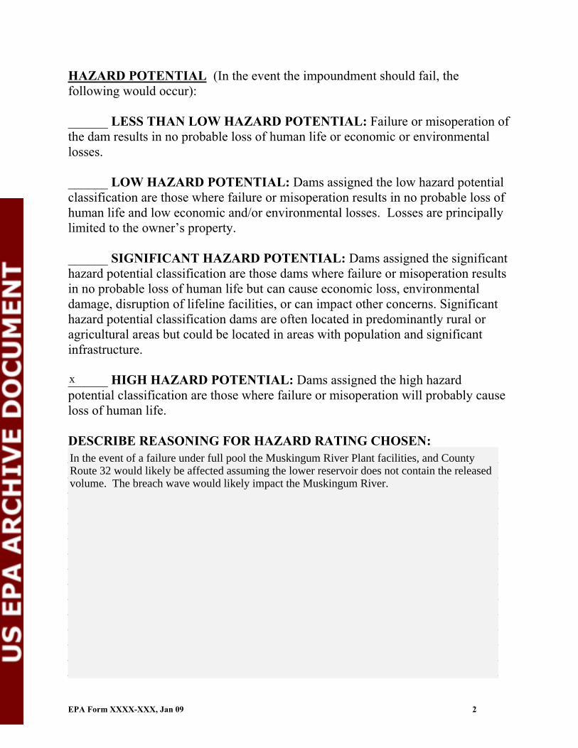
HAZARD POTENTIAL (In the event the impoundment should fail, the following would occur):
______ LESS THAN LOW HAZARD POTENTIAL: Failure or misoperation of the dam results in no probable loss of human life or economic or environmental losses.
______ LOW HAZARD POTENTIAL: Dams assigned the low hazard potential classification are those where failure or misoperation results in no probable loss of human life and low economic and/or environmental losses. Losses are principally limited to the owner’s property.
______ SIGNIFICANT HAZARD POTENTIAL: Dams assigned the significant hazard potential classification are those dams where failure or misoperation results in no probable loss of human life but can cause economic loss, environmental damage, disruption of lifeline facilities, or can impact other concerns. Significant hazard potential classification dams are often located in predominantly rural or agricultural areas but could be located in areas with population and significant infrastructure.
______ HIGH HAZARD POTENTIAL: Dams assigned the high hazard potential classification are those where failure or misoperation will probably cause loss of human life.
DESCRIBE REASONING FOR HAZARD RATING CHOSEN: _______________________________________________________________________________________________________________________________________________________________________________________________________________________________________________________________________________________________________________________________________________________________________________________________________________________________________________________________________________________________________________________________________________________________________________________________________________________________________________________________________________________________________________________________________________________________________________________________________________________________________________________________________________________________________________________________________________________________________________________________________________
EPA Form XXXX-XXX, Jan 09 2
x
In the event of a failure under full pool the Muskingum River Plant facilities, and CountyRoute 32 would likely be affected assuming the lower reservoir does not contain the releasedvolume. The breach wave would likely impact the Muskingum River.

CONFIGURATION:
Height original ground
CROSS-VALLEY
Height original ground
SIDE-HILL
Water or ccw
DIKED
original ground Height
Height original ground
CROSS-VALLEY
Water or ccw
original ground
SIDE-HILL
Height original ground
CROSS-VALLEY
original ground
SIDE-HILL
original ground
SIDE-HILL
original ground
SIDE-HILL
original original ground ground
SIDE-HILLSIDE-HILL
original ground
SIDE-HILLSIDE-HILL
original ground Height
SIDE-HILLSIDE-HILLSIDE-HILL
Height Height original ground original ground Height
SIDE-HILL
original ground Height
SIDE-HILL
Water or ccw
original ground Height
SIDE-HILL
INCISED
Water or ccw
original ground
_____ Cross-Valley _____ Side-Hill _____ Diked _____ Incised (form completion optional)_____ Combination Incised/Diked Embankment Height __________ feet Embankment Material_______________Pool Area __________________ acres Liner ____________________________ Current Freeboard ___________ feet Liner Permeability _________________
EPA Form XXXX-XXX, Jan 09 3
x
100 Clay and bottom ash(approximation) 40 none
5 n/a

TYPE OF OUTLET (Mark all that apply)
TRAPEZOIDAL
Avg Depth
Bottom Width
Depth
TRIANGULAR_____ Open Channel Spillway_____ Trapezoidal Top Width Top Width
_____ Triangular
RECTANGULAR IRREGULAR
Depth _____ Rectangular _____ Irregular
_____ depth _____ bottom (or average) width
Width
Depth
Average Width
_____ top width
_____ Outlet
_____ inside diameter
Material Inside Diameter
_____ corrugated metal _____ welded steel _____ concrete _____ plastic (hdpe, pvc, etc.) _____ other (specify) ____________________
Is water flowing through the outlet? YES _______ NO _______
_____ No Outlet
_____ Other Type of Outlet (specify) ________________________________
The Impoundment was Designed By ______________________________________________________________________________________________________
EPA Form XXXX-XXX, Jan 09 4
x
x
2'50'
x
42 "
x
x
AEP with Casagrande

Has there ever been a failure at this site? YES __________ NO ___________
If So When? ___________________________
If So Please Describe : _____________________________________________________________________________________________________________________________________________________________________________________________________________________________________________________________________________________________________________________________________________________________________________________________________________________________________________________________________________________________________________________________________________________________________________________________________________________________________________________________________________________________________________________________________________________________________________________________________________________________________________________________________________________________________________________________________________________________________________________________________________________________________________________________________________________________________________________________________________________________________________________________________________________________________________________________________________________________________________________________________________________________________________________________________________________________________________________________________________________________________________________________________________________________________________________________________________________________________________________________________________________________________________________________________________________________________________________________________________________________________________________________________________________________________________________________________________________________________________________________________________________________________________________________________________________________________________________________________________________________________________________________________________________________________________
EPA Form XXXX-XXX, Jan 09 5
x
n/a

Has there ever been significant seepages at this site? YES _______ NO _______
If So When? ___________________________
IF So Please Describe: _______________________________________________________________________________________________________________________________________________________________________________________________________________________________________________________________________________________________________________________________________________________________________________________________________________________________________________________________________________________________________________________________________________________________________________________________________________________________________________________________________________________________________________________________________________________________________________________________________________________________________________________________________________________________________________________________________________________________________________________________________________________________________________________________________________________________________________________________________________________________________________________________________________________________________________________________________________________________________________________________________________________________________________________________________________________________________________________________________________________________________________________________________________________________________________________________________________________________________________________________________________________________________________________________________________________________________________________________________________________________________________________________________________________________________________________________________________________________________________________________________________________________________________________________________________________________________________________________________________________________________________________________________________________________________________
EPA Form XXXX-XXX, Jan 09 6
x

Has there ever been any measures undertaken to monitor/lowerPhreatic water table levels based on past seepages or breaches at this site? YES ________NO ________
If so, which method (e.g., piezometers, gw pumping,...)? ____________________
If so Please Describe : ____________________________________________________________________________________________________________________________________________________________________________________________________________________________________________________________________________________________________________________________________________________________________________________________________________________________________________________________________________________________________________________________________________________________________________________________________________________________________________________________________________________________________________________________________________________________________________________________________________________________________________________________________________________________________________________________________________________________________________________________________________________________________________________________________________________________________________________________________________________________________________________________________________________________________________________________________________________________________________________________________________________________________________________________________________________________________________________________________________________________________________________________________________________________________________________________________________________________________________________________________________________________________________________________________________________________________________________________________________________________________________________________________________________________________________________________________________________________________________________________________________________________________________________________________________________________________________________________________________________________________________________________________________________________________________
EPA Form XXXX-XXX, Jan 09 7
x

Site Name: Date:Unit Name: Operator's Name: Unit I.D.: Hazard Potential Classification: High Significant Low
Inspector's Name:
Coal Combustion Dam Inspection Checklist FormUS EnvironmentalProtection Agency
Check the appropriate box below. Provide comments when appropriate. If not applicable or not available, record "N/A". Any unusual conditions or construction practices that should be noted in the comments section. For large diked embankments, separate checklists may be used for different embankment areas. If separate forms are used, identify approximate area that the form applies to in comments.
Yes No Yes No
1. Frequency of Company's Dam Inspections? 18. Sloughing or bulging on slopes?
2. Pool elevation (operator records)? 19. Major erosion or slope deterioration?
3. Decant inlet elevation (operator records)? 20. Decant Pipes:
4. Open channel spillway elevation (operator records)? Is water entering inlet, but not exiting outlet?
5. Lowest dam crest elevation (operator records)? Is water exiting outlet, but not entering inlet?
6. If instrumentation is present, are readings recorded (operator records)? Is water exiting outlet flowing clear?
7. Is the embankment currently under construction? 21. Seepage (specify location, if seepage carries fines, and approximate seepage rate below):
8. Foundation preparation (remove vegetation,stumps, topsoil in area where embankment fill will be placed)? From underdrain?
9. Trees growing on embankment? (If so, indicate largest diameter below) At isolated points on embankment slopes?
10. Cracks or scarps on crest? At natural hillside in the embankment area?
11. Is there significant settlement along the crest? Over widespread areas?
12. Are decant trashracks clear and in place? From downstream foundation area?
13. Depressions or sinkholes in tailings surface orwhirlpool in the pool area? "Boils" beneath stream or ponded water?
14. Clogged spillways, groin or diversion ditches? Around the outside of the decant pipe?
15. Are spillway or ditch linings deteriorated? 22. Surface movements in valley bottom or on hillside?
16. Are outlets of decant or underdrains blocked? 23. Water against downstream toe?
17. Cracks or scarps on slopes? 24. Were Photos taken during the dam inspection?
Major adverse changes in these items could cause instability and should be reported forfurther evaluation. Adverse conditions noted in these items should normally be described (extent, location, volume, etc.) in the space below and on the back of this sheet.
Inspection Issue # Comments
EPA FORM -XXXX
Muskingum River Power Plant October 21, 2009
Muskingum River Lower Fly Ash Dam American Electric Power
OH00972
Malcolm D. Hargraves P.E. /Rebecca Filkins
quarterly
715.6 see
715.6
n/a
725
x x
x
note
x
x
xn/a
x
x
x
x
x
x
x
x
x
xx
x
x
x
x
x
x
x
x
N/A = Not Applicable/Available.
19 Isolated, grassed erosion rills noted on downstream slope, one of which was likely an old sluice pipe location.
Beaching erosion noted is some places on upstream slope, creating about a 1 foot drop/exposed face.
23 Water against downstream toe (rip rap protected) is from waste water pond for the facility.
21 Seepage noted from rock toe near waste water pond elevation and from active drain near left abutment/rock
toe buttress contact. There may or may not be an underdrain at this location. Seepage appeared clear.
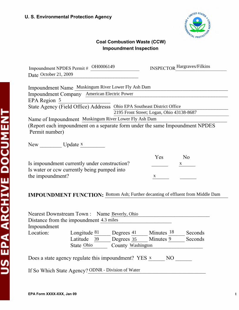
U. S. Environmental Protection Agency
Coal Combustion Waste (CCW)Impoundment Inspection
Impoundment NPDES Permit # _____________________ INSPECTOR______________________Date ____________________________________
Impoundment Name ________________________________________________________Impoundment Company ____________________________________________________EPA Region ___________________State Agency (Field Office) Addresss __________________________________________
__________________________________________Name of Impoundment _____________________________________________________(Report each impoundment on a separate form under the same Impoundment NPDES Permit number)
New ________ Update _________
Yes NoIs impoundment currently under construction? ______ ______Is water or ccw currently being pumped into the impoundment? ______ ______
IMPOUNDMENT FUNCTION: _____________________________________________
Nearest Downstream Town : Name ____________________________________Distance from the impoundment __________________________ ImpoundmentLocation: Longitude ______ Degrees ______ Minutes ______ Seconds Latitude ______ Degrees ______ Minutes ______ Seconds
State _________ County ___________________________
Does a state agency regulate this impoundment? YES ______ NO ______
If So Which State Agency?___________________________________________
EPA Form XXXX-XXX, Jan 09 1
OH0006149 Hargraves/Filkins
October 21, 2009
Muskingum River Lower Fly Ash Dam
American Electric Power5
Ohio EPA Southeast District Office2195 Front Street; Logan, Ohio 43138-8687
Muskingum River Lower Fly Ash Dam
x
x
x
Bottom Ash; Further decanting of effluent from Middle Dam
Beverly, Ohio4.3 miles
81 41 18
39 35 9Ohio Washington
x
ODNR - Division of Water

HAZARD POTENTIAL (In the event the impoundment should fail, the following would occur):
______ LESS THAN LOW HAZARD POTENTIAL: Failure or misoperation of the dam results in no probable loss of human life or economic or environmental losses.
______ LOW HAZARD POTENTIAL: Dams assigned the low hazard potential classification are those where failure or misoperation results in no probable loss of human life and low economic and/or environmental losses. Losses are principally limited to the owner’s property.
______ SIGNIFICANT HAZARD POTENTIAL: Dams assigned the significant hazard potential classification are those dams where failure or misoperation results in no probable loss of human life but can cause economic loss, environmental damage, disruption of lifeline facilities, or can impact other concerns. Significant hazard potential classification dams are often located in predominantly rural or agricultural areas but could be located in areas with population and significant infrastructure.
______ HIGH HAZARD POTENTIAL: Dams assigned the high hazard potential classification are those where failure or misoperation will probably cause loss of human life.
DESCRIBE REASONING FOR HAZARD RATING CHOSEN: _______________________________________________________________________________________________________________________________________________________________________________________________________________________________________________________________________________________________________________________________________________________________________________________________________________________________________________________________________________________________________________________________________________________________________________________________________________________________________________________________________________________________________________________________________________________________________________________________________________________________________________________________________________________________________________________________________________________________________________________________________________
EPA Form XXXX-XXX, Jan 09 2
x
In the event of a failure under full pool the Muskingum River Plant facilities and CountyRoute 32 would likely be affected. The breach wave would likely impact the MuskingumRiver.

CONFIGURATION:
Height original ground
CROSS-VALLEY
Height original ground
SIDE-HILL
Water or ccw
DIKED
original ground Height
Height original ground
CROSS-VALLEY
Water or ccw
original ground
SIDE-HILL
Height original ground
CROSS-VALLEY
original ground
SIDE-HILL
original ground
SIDE-HILL
original ground
SIDE-HILL
original original ground ground
SIDE-HILLSIDE-HILL
original ground
SIDE-HILLSIDE-HILL
original ground Height
SIDE-HILLSIDE-HILLSIDE-HILL
Height Height original ground original ground Height
SIDE-HILL
original ground Height
SIDE-HILL
Water or ccw
original ground Height
SIDE-HILL
INCISED
Water or ccw
original ground
_____ Cross-Valley _____ Side-Hill _____ Diked _____ Incised (form completion optional)_____ Combination Incised/Diked Embankment Height __________ feet Embankment Material_______________Pool Area __________________ acres Liner ____________________________ Current Freeboard ___________ feet Liner Permeability _________________
EPA Form XXXX-XXX, Jan 09 3
x
75 Earth and bottom ash(approximation) 16 none
9.4 n/a

TYPE OF OUTLET (Mark all that apply)
TRAPEZOIDAL
Avg Depth
Bottom Width
Depth
TRIANGULAR_____ Open Channel Spillway_____ Trapezoidal Top Width Top Width
_____ Triangular
RECTANGULAR IRREGULAR
Depth _____ Rectangular _____ Irregular
_____ depth _____ bottom (or average) width
Width
Depth
Average Width
_____ top width
_____ Outlet
_____ inside diameter
Material Inside Diameter
_____ corrugated metal _____ welded steel _____ concrete _____ plastic (hdpe, pvc, etc.) _____ other (specify) ____________________
Is water flowing through the outlet? YES _______ NO _______
_____ No Outlet
_____ Other Type of Outlet (specify) ________________________________
The Impoundment was Designed By ______________________________________________________________________________________________________
EPA Form XXXX-XXX, Jan 09 4
n/a
x
72
x
x
x Begins as 54" dia. concrete pipe at spillway
AEP with Casagrande

Has there ever been a failure at this site? YES __________ NO ___________
If So When? ___________________________
If So Please Describe : _____________________________________________________________________________________________________________________________________________________________________________________________________________________________________________________________________________________________________________________________________________________________________________________________________________________________________________________________________________________________________________________________________________________________________________________________________________________________________________________________________________________________________________________________________________________________________________________________________________________________________________________________________________________________________________________________________________________________________________________________________________________________________________________________________________________________________________________________________________________________________________________________________________________________________________________________________________________________________________________________________________________________________________________________________________________________________________________________________________________________________________________________________________________________________________________________________________________________________________________________________________________________________________________________________________________________________________________________________________________________________________________________________________________________________________________________________________________________________________________________________________________________________________________________________________________________________________________________________________________________________________________________________________________________________________
EPA Form XXXX-XXX, Jan 09 5
x
1968-1969
Excessive seepage and slope softening occurred during early stages of embankment constructionand first filling. A breach did not occur as a result. Additional rip-rap buttressing and drainagewas placed at this time on the downstream face at the highest portion of the dam to address theproblem.

Has there ever been significant seepages at this site? YES _______ NO _______
If So When? ___________________________
IF So Please Describe: _______________________________________________________________________________________________________________________________________________________________________________________________________________________________________________________________________________________________________________________________________________________________________________________________________________________________________________________________________________________________________________________________________________________________________________________________________________________________________________________________________________________________________________________________________________________________________________________________________________________________________________________________________________________________________________________________________________________________________________________________________________________________________________________________________________________________________________________________________________________________________________________________________________________________________________________________________________________________________________________________________________________________________________________________________________________________________________________________________________________________________________________________________________________________________________________________________________________________________________________________________________________________________________________________________________________________________________________________________________________________________________________________________________________________________________________________________________________________________________________________________________________________________________________________________________________________________________________________________________________________________________________________________________________________________________
EPA Form XXXX-XXX, Jan 09 6
See failure discussion for initial time period. Excessive seepage began to be evident againduring the late 1980's after being dormant for some time. Information regarding the nature ofthe seepage (turbidity, ash laden, etc.) at that time was not available at the time this check listwas completed.
1968-1968, 1989-1990
x

Has there ever been any measures undertaken to monitor/lowerPhreatic water table levels based on past seepages or breaches at this site? YES ________NO ________
If so, which method (e.g., piezometers, gw pumping,...)? ____________________
If so Please Describe : ____________________________________________________________________________________________________________________________________________________________________________________________________________________________________________________________________________________________________________________________________________________________________________________________________________________________________________________________________________________________________________________________________________________________________________________________________________________________________________________________________________________________________________________________________________________________________________________________________________________________________________________________________________________________________________________________________________________________________________________________________________________________________________________________________________________________________________________________________________________________________________________________________________________________________________________________________________________________________________________________________________________________________________________________________________________________________________________________________________________________________________________________________________________________________________________________________________________________________________________________________________________________________________________________________________________________________________________________________________________________________________________________________________________________________________________________________________________________________________________________________________________________________________________________________________________________________________________________________________________________________________________________________________________________________________
EPA Form XXXX-XXX, Jan 09 7
piezometers, slurry wall
x
In 1991 AEP installed a slurry wall through the dam to form a seepage cut off. Piezometershave been installed as a part of routine monitoring protocol for the embankment and to measurethe effectiveness of the cutoff wall.

Site Name: Date:Unit Name: Operator's Name: Unit I.D.: Hazard Potential Classification: High Significant Low
Inspector's Name:
Coal Combustion Dam Inspection Checklist FormUS EnvironmentalProtection Agency
Check the appropriate box below. Provide comments when appropriate. If not applicable or not available, record "N/A". Any unusual conditions or construction practices that should be noted in the comments section. For large diked embankments, separate checklists may be used for different embankment areas. If separate forms are used, identify approximate area that the form applies to in comments.
Yes No Yes No
1. Frequency of Company's Dam Inspections? 18. Sloughing or bulging on slopes?
2. Pool elevation (operator records)? 19. Major erosion or slope deterioration?
3. Decant inlet elevation (operator records)? 20. Decant Pipes:
4. Open channel spillway elevation (operator records)? Is water entering inlet, but not exiting outlet?
5. Lowest dam crest elevation (operator records)? Is water exiting outlet, but not entering inlet?
6. If instrumentation is present, are readings recorded (operator records)? Is water exiting outlet flowing clear?
7. Is the embankment currently under construction? 21. Seepage (specify location, if seepage carries fines, and approximate seepage rate below):
8. Foundation preparation (remove vegetation,stumps, topsoil in area where embankment fill will be placed)? From underdrain?
9. Trees growing on embankment? (If so, indicate largest diameter below) At isolated points on embankment slopes?
10. Cracks or scarps on crest? At natural hillside in the embankment area?
11. Is there significant settlement along the crest? Over widespread areas?
12. Are decant trashracks clear and in place? From downstream foundation area?
13. Depressions or sinkholes in tailings surface orwhirlpool in the pool area? "Boils" beneath stream or ponded water?
14. Clogged spillways, groin or diversion ditches? Around the outside of the decant pipe?
15. Are spillway or ditch linings deteriorated? 22. Surface movements in valley bottom or on hillside?
16. Are outlets of decant or underdrains blocked? 23. Water against downstream toe?
17. Cracks or scarps on slopes? 24. Were Photos taken during the dam inspection?
Major adverse changes in these items could cause instability and should be reported forfurther evaluation. Adverse conditions noted in these items should normally be described (extent, location, volume, etc.) in the space below and on the back of this sheet.
Inspection Issue # Comments
EPA FORM -XXXX
Muskingum River Power Plant October 21, 2009
Units 1 - 4 Bottom Ash Pond Dam American Electric Power
OH00974
Malcolm D. Hargraves P.E. /Rebecca Filkins
quarterly
637
x
637
n/a
650
x x
x
x
x
n/an/a
n/a
x
x
x
xx
x
x
x
x
xx
x
x
x
x
x
x
x
N/A = Not Applicable/Available
9 Trees approaching 12 to 18 inches in diameter noted on east dike facing Muskingum River; Heavy vegetation
and trees noted on central and northerly portions of east dike where bottom ash stockpiling activities surcharged
17, 18 Isolated old slough/scarp noted below bench in recently cut, heavily vegetated area on south dike.
and buried dikes and obscured constructed dike/river bank interface. No free water has been in this area, which
may be slated for closure, for at least 20 years.
23 River at east dike rock toe buttress/drain in area of 1972 and 1988 slope failure where repairs were taken to
water surface and the dike flattened.

U. S. Environmental Protection Agency
Coal Combustion Waste (CCW)Impoundment Inspection
Impoundment NPDES Permit # _____________________ INSPECTOR______________________Date ____________________________________
Impoundment Name ________________________________________________________Impoundment Company ____________________________________________________EPA Region ___________________State Agency (Field Office) Addresss __________________________________________
__________________________________________Name of Impoundment _____________________________________________________(Report each impoundment on a separate form under the same Impoundment NPDES Permit number)
New ________ Update _________
Yes NoIs impoundment currently under construction? ______ ______Is water or ccw currently being pumped into the impoundment? ______ ______
IMPOUNDMENT FUNCTION: _____________________________________________
Nearest Downstream Town : Name ____________________________________Distance from the impoundment __________________________ ImpoundmentLocation: Longitude ______ Degrees ______ Minutes ______ Seconds Latitude ______ Degrees ______ Minutes ______ Seconds
State _________ County ___________________________
Does a state agency regulate this impoundment? YES ______ NO ______
If So Which State Agency?___________________________________________
EPA Form XXXX-XXX, Jan 09 1
OH0006149 Hargraves/Filkins
October 21, 2009
Units 1 - 4 Bottom Ash Pond Dam
American Electric Power5
Ohio EPA Southeast District Office2195 Front Street; Logan, Ohio 43138-8687
Units 1 - 4 Bottom Ash Pond Dam
x
x
x
Bottom Ash disposal and processing.
Beverly, Ohio3.9 miles
81 40 18
39 35 38Ohio Washington
x
ODNR - Division of Water

HAZARD POTENTIAL (In the event the impoundment should fail, the following would occur):
______ LESS THAN LOW HAZARD POTENTIAL: Failure or misoperation of the dam results in no probable loss of human life or economic or environmental losses.
______ LOW HAZARD POTENTIAL: Dams assigned the low hazard potential classification are those where failure or misoperation results in no probable loss of human life and low economic and/or environmental losses. Losses are principally limited to the owner’s property.
______ SIGNIFICANT HAZARD POTENTIAL: Dams assigned the significant hazard potential classification are those dams where failure or misoperation results in no probable loss of human life but can cause economic loss, environmental damage, disruption of lifeline facilities, or can impact other concerns. Significant hazard potential classification dams are often located in predominantly rural or agricultural areas but could be located in areas with population and significant infrastructure.
______ HIGH HAZARD POTENTIAL: Dams assigned the high hazard potential classification are those where failure or misoperation will probably cause loss of human life.
DESCRIBE REASONING FOR HAZARD RATING CHOSEN: _______________________________________________________________________________________________________________________________________________________________________________________________________________________________________________________________________________________________________________________________________________________________________________________________________________________________________________________________________________________________________________________________________________________________________________________________________________________________________________________________________________________________________________________________________________________________________________________________________________________________________________________________________________________________________________________________________________________________________________________________________________
EPA Form XXXX-XXX, Jan 09 2
x
In the event of a failure under full pool the breach wave would likely impact the MuskingumRiver.

CONFIGURATION:
Height original ground
CROSS-VALLEY
Height original ground
SIDE-HILL
Water or ccw
DIKED
original ground Height
Height original ground
CROSS-VALLEY
Water or ccw
original ground
SIDE-HILL
Height original ground
CROSS-VALLEY
original ground
SIDE-HILL
original ground
SIDE-HILL
original ground
SIDE-HILL
original original ground ground
SIDE-HILLSIDE-HILL
original ground
SIDE-HILLSIDE-HILL
original ground Height
SIDE-HILLSIDE-HILLSIDE-HILL
Height Height original ground original ground Height
SIDE-HILL
original ground Height
SIDE-HILL
Water or ccw
original ground Height
SIDE-HILL
INCISED
Water or ccw
original ground
_____ Cross-Valley _____ Side-Hill _____ Diked _____ Incised (form completion optional)_____ Combination Incised/Diked Embankment Height __________ feet Embankment Material_______________Pool Area __________________ acres Liner ____________________________ Current Freeboard ___________ feet Liner Permeability _________________
EPA Form XXXX-XXX, Jan 09 3
x
33 Earth fill(approximation) 5 none
13 n/a
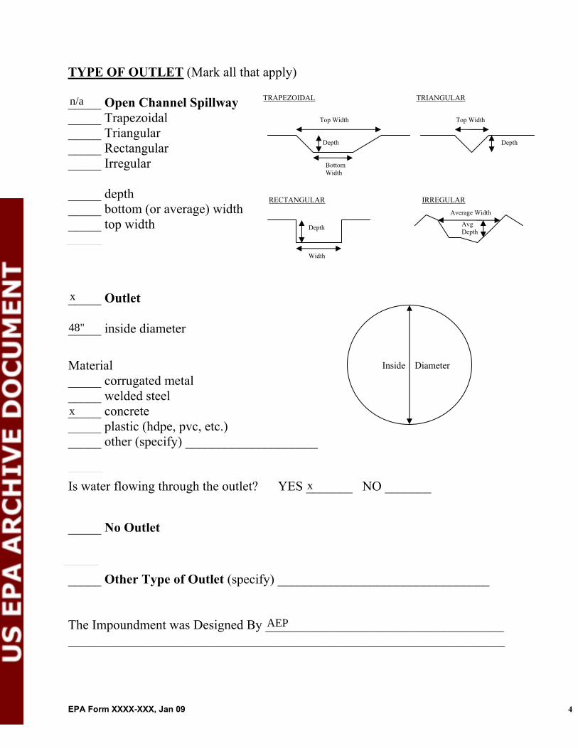
TYPE OF OUTLET (Mark all that apply)
TRAPEZOIDAL
Avg Depth
Bottom Width
Depth
TRIANGULAR_____ Open Channel Spillway_____ Trapezoidal Top Width Top Width
_____ Triangular
RECTANGULAR IRREGULAR
Depth _____ Rectangular _____ Irregular
_____ depth _____ bottom (or average) width
Width
Depth
Average Width
_____ top width
_____ Outlet
_____ inside diameter
Material Inside Diameter
_____ corrugated metal _____ welded steel _____ concrete _____ plastic (hdpe, pvc, etc.) _____ other (specify) ____________________
Is water flowing through the outlet? YES _______ NO _______
_____ No Outlet
_____ Other Type of Outlet (specify) ________________________________
The Impoundment was Designed By ______________________________________________________________________________________________________
EPA Form XXXX-XXX, Jan 09 4
n/a
x
48"
x
x
AEP

Has there ever been a failure at this site? YES __________ NO ___________
If So When? ___________________________
If So Please Describe : _____________________________________________________________________________________________________________________________________________________________________________________________________________________________________________________________________________________________________________________________________________________________________________________________________________________________________________________________________________________________________________________________________________________________________________________________________________________________________________________________________________________________________________________________________________________________________________________________________________________________________________________________________________________________________________________________________________________________________________________________________________________________________________________________________________________________________________________________________________________________________________________________________________________________________________________________________________________________________________________________________________________________________________________________________________________________________________________________________________________________________________________________________________________________________________________________________________________________________________________________________________________________________________________________________________________________________________________________________________________________________________________________________________________________________________________________________________________________________________________________________________________________________________________________________________________________________________________________________________________________________________________________________________________________________________
EPA Form XXXX-XXX, Jan 09 5
x
1972, 1988
Slope failures in the northern extremity of the east dike adjacent to where the bottom ash sluicepipes enter the pond occurred in 1972 and again in 1988. These failures also involved the riverbank in this location. A breach of the dike did not occur as a result of these failures, but theywere extensive enough to eventually require a rock toe buttress and drain, along with flatteningthe dike slope and slightly widening the crest. The rock toe buttress effectively extended thedike toe to and beyond the river bank.

Has there ever been significant seepages at this site? YES _______ NO _______
If So When? ___________________________
IF So Please Describe: _______________________________________________________________________________________________________________________________________________________________________________________________________________________________________________________________________________________________________________________________________________________________________________________________________________________________________________________________________________________________________________________________________________________________________________________________________________________________________________________________________________________________________________________________________________________________________________________________________________________________________________________________________________________________________________________________________________________________________________________________________________________________________________________________________________________________________________________________________________________________________________________________________________________________________________________________________________________________________________________________________________________________________________________________________________________________________________________________________________________________________________________________________________________________________________________________________________________________________________________________________________________________________________________________________________________________________________________________________________________________________________________________________________________________________________________________________________________________________________________________________________________________________________________________________________________________________________________________________________________________________________________________________________________________________________
EPA Form XXXX-XXX, Jan 09 6
x

Has there ever been any measures undertaken to monitor/lowerPhreatic water table levels based on past seepages or breaches at this site? YES ________NO ________
If so, which method (e.g., piezometers, gw pumping,...)? ____________________
If so Please Describe : ____________________________________________________________________________________________________________________________________________________________________________________________________________________________________________________________________________________________________________________________________________________________________________________________________________________________________________________________________________________________________________________________________________________________________________________________________________________________________________________________________________________________________________________________________________________________________________________________________________________________________________________________________________________________________________________________________________________________________________________________________________________________________________________________________________________________________________________________________________________________________________________________________________________________________________________________________________________________________________________________________________________________________________________________________________________________________________________________________________________________________________________________________________________________________________________________________________________________________________________________________________________________________________________________________________________________________________________________________________________________________________________________________________________________________________________________________________________________________________________________________________________________________________________________________________________________________________________________________________________________________________________________________________________________________________
EPA Form XXXX-XXX, Jan 09 7
x