assessment of damage and residual load bearing … · 1 molkens, t., van coile, r., & gernay,...
TRANSCRIPT

1 Molkens, T., Van Coile, R., & Gernay, T. (2017). Assessment of damage and residual load bearing capacity of a concrete slab after fire: Applied reliability-based methodology. Engineering Structures, 150, 969-985.
Assessment of damage and residual load bearing capacity of a concrete slab after fire: applied reliability-based methodology
ABSTRACT
For most fires occurring in buildings with a concrete structural frame, the structural elements do not collapse during fire exposure, and further use of the building after fire may be possible. Fire can nevertheless result in a permanent loss of strength and thus a post-fire evaluation of the residual load bearing capacity has to be made to inform decisions on continued use and the need for structural repairs. This evaluation is however particularly difficult due to the many uncertainties associated with both the fire exposure and the characteristics of the structural elements. These uncertainties cannot be neglected when determining the residual capacity since adequate safety is a major societal concern as indicated by the predominance of safety in current design standards and guidance documents. In this paper a comprehensive methodology is presented for the assessment of the residual capacity of concrete structures after exposure to fire. The methodology is introduced through application to a real-life case study of an apartment fire with a focus on the end-span of the affected continuous concrete slab. It results in a reliability-based evaluation of the maximum allowable characteristic value for the imposed load on the slab. The presented methodology is useful to make informed decision about continued use of structures after a fire event.
Keywords
Concrete structure, post-fire assessment, residual capacity, safety level, reliability analysis, numerical modelling, simple method, Eurocode
1 INTRODUCTION Current codes and provisions for fire design of building structures have been developed focussing on the objective of life safety protection (Spinardi et al., 2017). Accordingly, performance requirements are primarily designed to ensure sufficient evacuation time for building occupants and provide safety for the fire brigade during search and rescue operations. There is on the other hand minimal consideration on property protection or structural recovery after the fire (Mostafaei et al. 2014).
Recently though, the problem of maintaining functionality and ensuring fast recovery for buildings and other infrastructures affected by an accidental event such as fire has gained increasing attention. This shift is driven by a common understanding that the built environment needs to be resilient, i.e. able to absorb disruptions and bounce back rapidly (Bocchini et al., 2014). Resilience is of particular importance in a context of accelerating urbanization, where city infrastructure systems are under strain and any disruption can have major socio-economic

2 Molkens, T., Van Coile, R., & Gernay, T. (2017). Assessment of damage and residual load bearing capacity of a concrete slab after fire: Applied reliability-based methodology. Engineering Structures, 150, 969-985.
impacts. For instance, closing down of a school, a hospital or a bridge after a fire event would result in significant indirect economic cost. Therefore, performance requirements for structures under fire need to evolve towards incorporating property protection. Meanwhile, new methods need to be developed to be able to assess the level of damage, or the residual safety level, of structures after a fire. These methods are required to ease and accelerate the decision-making process following a disaster by providing sound information about the condition of the structure. Indeed, decision makers need to know whether a building can be re-used as is, needs structural repair, or should be demolished and rebuilt. Any delay in the decision process translates into a longer loss of functionality.
Assessing the condition of a structure after a fire is, however, a difficult task. Indeed, engineers face fundamental lack of information about the following elements:
• The fire event: the spatial and temporal distribution of temperatures to which the structure has been subjected is largely unknown. Hence, engineers must use models and indirect measures to infer the fire severity, or have to rely on expert judgement.
• The characteristics of the structure prior to the event: as-built drawings may not be available. Further, the structure may have been modified or may have experienced degradation during its lifetime.
• The effect of the fire on the structure and the residual material properties: estimations can be made through models and calculations, but this inevitably introduces simplifying assumptions and modelling uncertainties.
Given the many uncertainties mentioned above, the assessment of the post-fire condition of a structure needs to rely on a rigorous methodology. The objective of this research is to propose such a methodology. Emphasis is put on the post-fire load bearing capacity of concrete structures, but the methodology could easily be applied to other types of structures. The work adopts a reliability-based approach to quantify the residual load bearing capacity of a concrete structural element after a fire. This approach allows making the link with the reliability-based philosophy of the initial design by providing a clear understanding of the residual safety after the event. For practicality, the result is expressed in terms of maximum allowable imposed load for a given target safety level for the post-fire assessment (for instance, equal to the safety level of the initial design).
The presented work focuses on a reinforced concrete slab, which is one of the most common structural elements in buildings and infrastructure. Recent efforts directed at improving (the understanding of) the resilience of concrete and composite slabs with respect to fire include amongst others fragility assessments through expert-judgement (Ioannou et al., 2017), detailed reliability assessments (Van Coile, 2015) and an application of the PEER framework (Lange et al., 2014). In this paper a more direct approach is followed where the residual capacity is directly assessed after a specific fire event. The considered slab is typical of a multi-story apartment building, with a part working in cantilever (balcony). Non-fire related degradation effects (e.g. reinforcement corrosion) are however not explicitly considered in this paper. In function of the assessed case, influences of degradation should be taken into account in the methodology through the characteristics of the fire-exposed structural element (e.g. reinforcement area, concrete compressive strength).

3 Molkens, T., Van Coile, R., & Gernay, T. (2017). Assessment of damage and residual load bearing capacity of a concrete slab after fire: Applied reliability-based methodology. Engineering Structures, 150, 969-985.
The proposed methodology starts from the observation of a fire event and the collection of data and goes through the different steps up to the estimation of the maximum allowable imposed load. It makes use of a combination of forensic investigation (e.g. on-site measurements, discussion with firefighters and building designers), simplified methods, advanced numerical modelling (e.g. by finite element method), reliability-based methods, and engineering judgment. Throughout the paper, the method is illustrated by a real case study.
The application of reliability concepts allows to make a post-fire assessment which is in agreement with the safety philosophy of the Eurocodes (EN 1990). For background to the Eurocode philosophy and reliability concepts, reference is made to the Designer’s guide to EN 1990 (Gulvanessian et al., 2002) and the Probabilistic Model Code (JCSS, 2007). Basic concepts are introduced further in the paper.
The paper is structured as follows. In Section 2, the problem of safety level in post-fire assessment is discussed and the proposed general approach is presented. Section 3 introduces the case study, a fire event in a concrete apartment building in Belgium. Section 4 focuses on the determination of the fire severity and a comparison with observed structural damage, whereas Section 5 presents the reliability-based method for assessment of the post-fire load bearing capacity. Finally, the paper ends with a discussion (Section 6) and conclusive remarks (Section 7).
2 PROBLEM STATEMENT
2.1 Safety level in post-fire assessment Evaluating the post-fire load bearing capacity of concrete elements has received considerable interest in recent years. Experimental test programs have been reported for example by Chen et al. (2009) and El-Hawary et al. (1995). Combined experimental and numerical studies can be found for example in Jau and Huang (2008) and Raouffard and Nishiyama (2016), while Kodur and Agrawal (2016) and Kodur et al. (2013) focussed on developing more practical numerical methods for post-fire assessment. None of these research projects however take into account the issue of structural safety. If the analysis is limited to a single deterministic calculation of the load bearing capacity, laborious and detailed analyses can be performed, but the available safety level remains unknown.
As discussed in the Introduction, many uncertainties are associated with both the fire duration and the effect of elevated temperatures on the residual mechanical properties of the materials. Therefore, the load bearing capacity after fire exposure should be assessed based on reliability considerations, aiming to provide an adequate level of safety. Providing an adequate level of safety is not a trivial consideration and is on the contrary at the very heart of most modern structural design standards as for example the Eurocodes. EN 1990 (2002) specifies a target reliability index (safety level) βt,50 of 3.8 for a 50 year reference period tref, for structures with intermediate consequences of failure. This reliability index is related to a maximum allowable (target) probability of failure Pf,50 through the general relationship of equation (1), with Φ the cumulative standard normal distribution function. The safety target of the Eurocodes is for the
4 Molkens, T., Van Coile, R., & Gernay, T. (2017). Assessment of damage and residual load bearing capacity of a concrete slab after fire: Applied reliability-based methodology. Engineering Structures, 150, 969-985.
European Union anchored to legal requirements through the Construction Products Regulation (EU, 2011).
( )fP β= Φ − (1)
When a post-fire assessment intends to conform with the requirements of EN 1990 (or at least with its underlying focus on safety), reliability-based calculations have to be performed. In the framework of the Eurocodes the reliability considerations have been incorporated through the partial safety factors, but for the post-fire assessment of concrete elements no such partial factors exits, leaving the assessing engineer in principle with an explicit full-probabilistic calculation as the only option. This type of calculation can however be considered too complex and time-consuming for practical use. A simplified calculation tool has been presented in (Van Coile, 2015) which allows to take into account reliability requirements in a user-friendly way. The tool will be further denoted as the ReAssess-method referring both to the reliability background of the tool and to the fact that the method re-assesses the structure after fire in order to determine the reusability of structural elements. In this paper the ReAssess method is for the first time applied to a real-life case study and the specifics of the method are adapted to consider the specifics of this case study. Details of the ReAssess method are discussed further in Section 5, and theoretical applications to the post-fire assessment of concrete elements have been presented in (Van Coile, 2015) and (Van Coile et al., 2015).
It is emphasized that the proposed approach relates to the post-fire assessment of structural elements, not structural systems. This corresponds with the traditional Eurocode approach where structural systems are designed through requirements on their constituent elements. The above has important consequences. Firstly, although the safety level of the constituent elements may be ensured, the reliability obtained by the structural system remains unknown (as is the case for the Eurocode design rules). Generally, the global structural system can be expected to obtain a safety level exceeding the target safety level of the constituent elements, as acknowledged summarily in EN 1990 (2002). This is however not always the case as for example a series system of not fully correlated elements will have a higher failure probability than the failure probability of the constituent members. The methodology presented further is however in full agreement with the current Eurocode design philosophy and the current paper thus limit its analysis to the post-fire assessment of a single element. Secondly, the safety of the system requires that the connections between structural elements can fulfil their function. In other words, applying the proposed approach for evaluating the post-fire capacity of different structural elements, see (Van Coile, 2015) for derivations for concrete beams, columns and simply supported slabs, does not release the assessing engineer from his duty to assess the post-fire status of the connections between the elements (where applicable). In principle the ReAssess method can be used to assess the post-fire safety of the connections as well, but the required analytical equations have so far not be determined. This remains an area of future research.

5 Molkens, T., Van Coile, R., & Gernay, T. (2017). Assessment of damage and residual load bearing capacity of a concrete slab after fire: Applied reliability-based methodology. Engineering Structures, 150, 969-985.
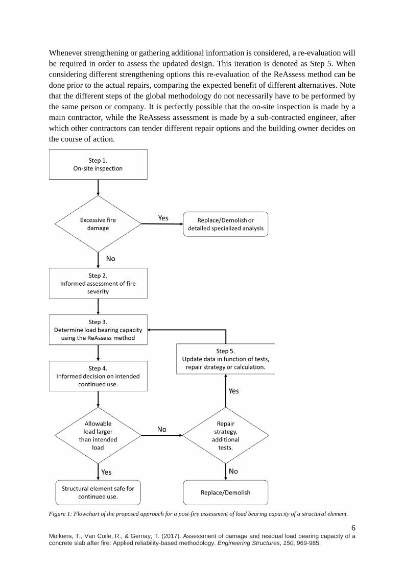
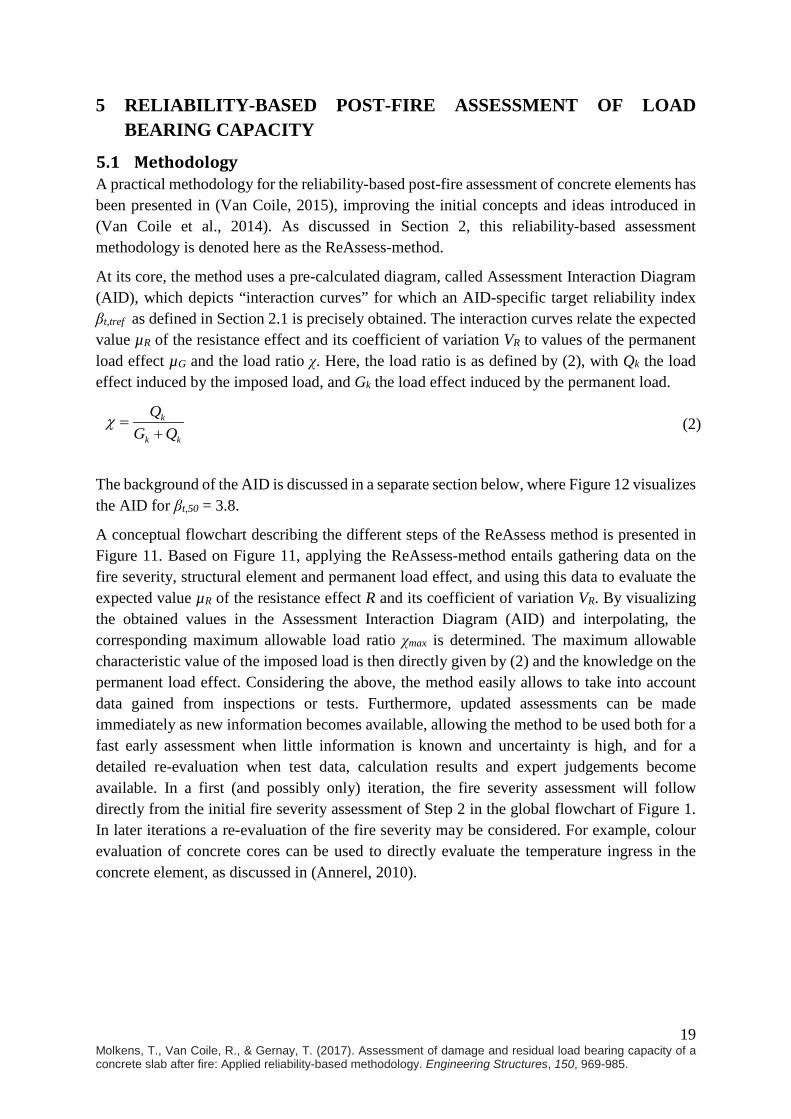
2.2 Proposed approach The proposed approach for the post-fire assessment of structural elements is indicated in Figure 1. The post-fire assessment necessarily starts with an on-site inspection of the structure in Step 1. This on-site inspection incorporates a visual inspection of the structure, the measurement of deformations when possible, and the gathering of basic relevant information regarding the fire event. Excessive deformations, local failures and distorted connections all indicate that replacing the corresponding elements may be required. These situations are denoted as “excessive fire damage” in Figure 1 and are outside the scope of the current paper.
Often the connections will not have been severely exposed to the fire and the visible damage of the structural elements may allow for the possibility of continued use. In those cases the problem lies in assessing the damage caused by the fire on the structure, and in making a safe assessment of the residual load bearing capacity. This requires knowledge of the severity of the fire attack to which the structure was exposed. Step 2 deals with the assessment of the fire severity after a fire event, considering the available information, and taking advantage of modelling tools if required to improve the initial assumptions. The detailed method applied here for the assessment of fire severity will be explained and applied to the case study in Section 4.
Once a first assessment of the fire severity is made, the ReAssess method is applied in Step 3 to determine the load bearing capacity. The ReAssess method yields the maximum allowable characteristic value of the imposed load that is associated with a pre-defined target safety level, taking into account the damage that was caused by the fire event. The ReAssess method will be adapted and applied to the case study in Section 5.
Step 4 consists of making an informed decision regarding the continued use of the structure. As the ReAssess method indicates the maximum allowable load from a safety perspective, multiple conclusions may be drawn depending on the results of the reliability assessment and on economic considerations, for example:
• Continued use of the structure is acceptable as the allowable load exceeds the design load.
• Tests should be performed in order to reduce the uncertainty regarding a number of input variables.*
• A change of use of the structure is most appropriate, as the load-bearing capacity is not sufficient for the original intended use but is sufficient for other purposes associated with lower requirements for the imposed load.
• Limited strengthening will allow the structure to regain its full capacity. • The structural element should be replaced as the costs of strengthening / repair are too
high.
* Reduced uncertainty will generally result in a higher safety level and thus in a higher allowable load. For example, testing the compressive strength will reduce the uncertainty. Naturally it is possible that additional tests will bring to light a more onerous situation than originally assessed, reducing the allowable load. Also, the use of more detailed models is considered under this label, allowing for a more precise evaluation. However, it is not recommended to increase complexity up to the point where external verification becomes difficult.
6 Molkens, T., Van Coile, R., & Gernay, T. (2017). Assessment of damage and residual load bearing capacity of a concrete slab after fire: Applied reliability-based methodology. Engineering Structures, 150, 969-985.
Whenever strengthening or gathering additional information is considered, a re-evaluation will be required in order to assess the updated design. This iteration is denoted as Step 5. When considering different strengthening options this re-evaluation of the ReAssess method can be done prior to the actual repairs, comparing the expected benefit of different alternatives. Note that the different steps of the global methodology do not necessarily have to be performed by the same person or company. It is perfectly possible that the on-site inspection is made by a main contractor, while the ReAssess assessment is made by a sub-contracted engineer, after which other contractors can tender different repair options and the building owner decides on the course of action.
Figure 1: Flowchart of the proposed approach for a post-fire assessment of load bearing capacity of a structural element.
7 Molkens, T., Van Coile, R., & Gernay, T. (2017). Assessment of damage and residual load bearing capacity of a concrete slab after fire: Applied reliability-based methodology. Engineering Structures, 150, 969-985.
3 PRESENTATION OF THE CASE STUDY AND ON-SITE INSPECTION
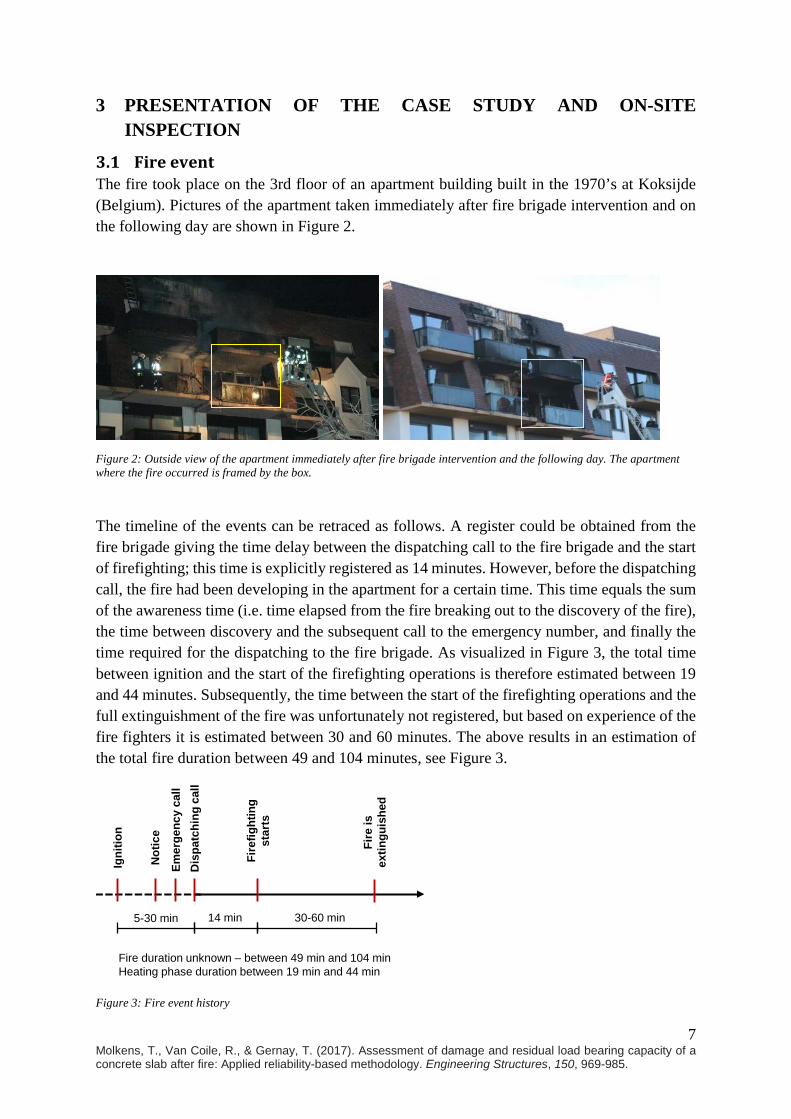
3.1 Fire event The fire took place on the 3rd floor of an apartment building built in the 1970’s at Koksijde (Belgium). Pictures of the apartment taken immediately after fire brigade intervention and on the following day are shown in Figure 2.
Figure 2: Outside view of the apartment immediately after fire brigade intervention and the following day. The apartment where the fire occurred is framed by the box.
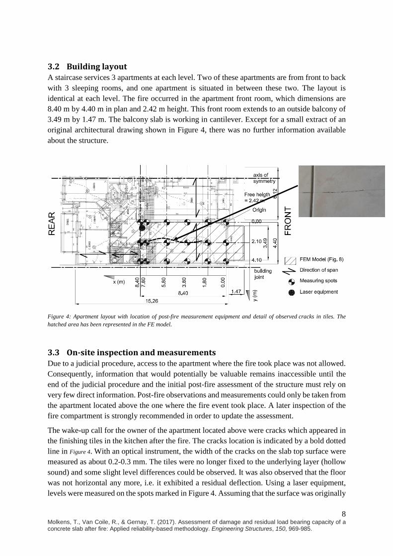
The timeline of the events can be retraced as follows. A register could be obtained from the fire brigade giving the time delay between the dispatching call to the fire brigade and the start of firefighting; this time is explicitly registered as 14 minutes. However, before the dispatching call, the fire had been developing in the apartment for a certain time. This time equals the sum of the awareness time (i.e. time elapsed from the fire breaking out to the discovery of the fire), the time between discovery and the subsequent call to the emergency number, and finally the time required for the dispatching to the fire brigade. As visualized in Figure 3, the total time between ignition and the start of the firefighting operations is therefore estimated between 19 and 44 minutes. Subsequently, the time between the start of the firefighting operations and the full extinguishment of the fire was unfortunately not registered, but based on experience of the fire fighters it is estimated between 30 and 60 minutes. The above results in an estimation of the total fire duration between 49 and 104 minutes, see Figure 3.
Figure 3: Fire event history
14 min 30-60 min5-30 min
Fire
fight
ing
star
ts
Dis
patc
hing
cal
lEm
erge
ncy
call
Igni
tion
Not
ice
Fire
is
extin
guis
hed
Fire duration unknown – between 49 min and 104 minHeating phase duration between 19 min and 44 min
8 Molkens, T., Van Coile, R., & Gernay, T. (2017). Assessment of damage and residual load bearing capacity of a concrete slab after fire: Applied reliability-based methodology. Engineering Structures, 150, 969-985.
3.2 Building layout A staircase services 3 apartments at each level. Two of these apartments are from front to back with 3 sleeping rooms, and one apartment is situated in between these two. The layout is identical at each level. The fire occurred in the apartment front room, which dimensions are 8.40 m by 4.40 m in plan and 2.42 m height. This front room extends to an outside balcony of 3.49 m by 1.47 m. The balcony slab is working in cantilever. Except for a small extract of an original architectural drawing shown in Figure 4, there was no further information available about the structure.
Figure 4: Apartment layout with location of post-fire measurement equipment and detail of observed cracks in tiles. The hatched area has been represented in the FE model.
3.3 On-site inspection and measurements Due to a judicial procedure, access to the apartment where the fire took place was not allowed. Consequently, information that would potentially be valuable remains inaccessible until the end of the judicial procedure and the initial post-fire assessment of the structure must rely on very few direct information. Post-fire observations and measurements could only be taken from the apartment located above the one where the fire event took place. A later inspection of the fire compartment is strongly recommended in order to update the assessment.
The wake-up call for the owner of the apartment located above were cracks which appeared in the finishing tiles in the kitchen after the fire. The cracks location is indicated by a bold dotted line in Figure 4. With an optical instrument, the width of the cracks on the slab top surface were measured as about 0.2-0.3 mm. The tiles were no longer fixed to the underlying layer (hollow sound) and some slight level differences could be observed. It was also observed that the floor was not horizontal any more, i.e. it exhibited a residual deflection. Using a laser equipment, levels were measured on the spots marked in Figure 4. Assuming that the surface was originally
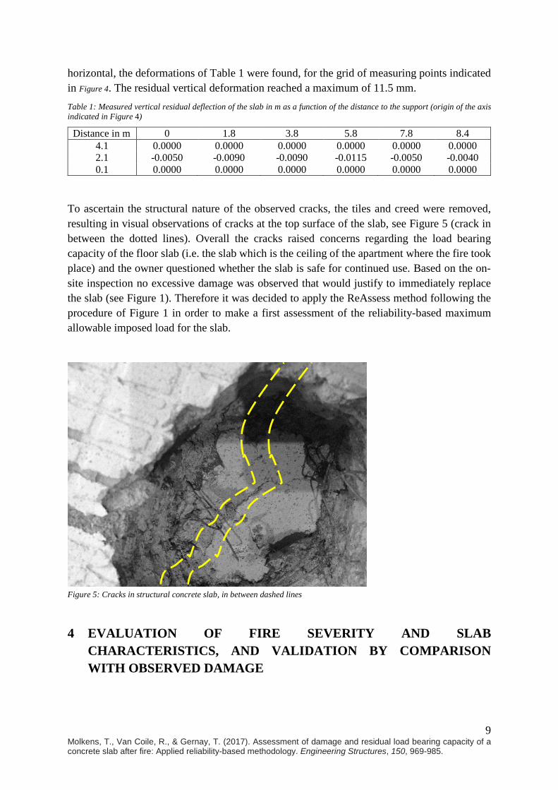
9 Molkens, T., Van Coile, R., & Gernay, T. (2017). Assessment of damage and residual load bearing capacity of a concrete slab after fire: Applied reliability-based methodology. Engineering Structures, 150, 969-985.
horizontal, the deformations of Table 1 were found, for the grid of measuring points indicated in Figure 4. The residual vertical deformation reached a maximum of 11.5 mm. Table 1: Measured vertical residual deflection of the slab in m as a function of the distance to the support (origin of the axis indicated in Figure 4)
Distance in m 0 1.8 3.8 5.8 7.8 8.4 4.1 0.0000 0.0000 0.0000 0.0000 0.0000 0.0000 2.1 -0.0050 -0.0090 -0.0090 -0.0115 -0.0050 -0.0040 0.1 0.0000 0.0000 0.0000 0.0000 0.0000 0.0000
To ascertain the structural nature of the observed cracks, the tiles and creed were removed, resulting in visual observations of cracks at the top surface of the slab, see Figure 5 (crack in between the dotted lines). Overall the cracks raised concerns regarding the load bearing capacity of the floor slab (i.e. the slab which is the ceiling of the apartment where the fire took place) and the owner questioned whether the slab is safe for continued use. Based on the on-site inspection no excessive damage was observed that would justify to immediately replace the slab (see Figure 1). Therefore it was decided to apply the ReAssess method following the procedure of Figure 1 in order to make a first assessment of the reliability-based maximum allowable imposed load for the slab.
Figure 5: Cracks in structural concrete slab, in between dashed lines
4 EVALUATION OF FIRE SEVERITY AND SLAB CHARACTERISTICS, AND VALIDATION BY COMPARISON WITH OBSERVED DAMAGE

10 Molkens, T., Van Coile, R., & Gernay, T. (2017). Assessment of damage and residual load bearing capacity of a concrete slab after fire: Applied reliability-based methodology. Engineering Structures, 150, 969-985.
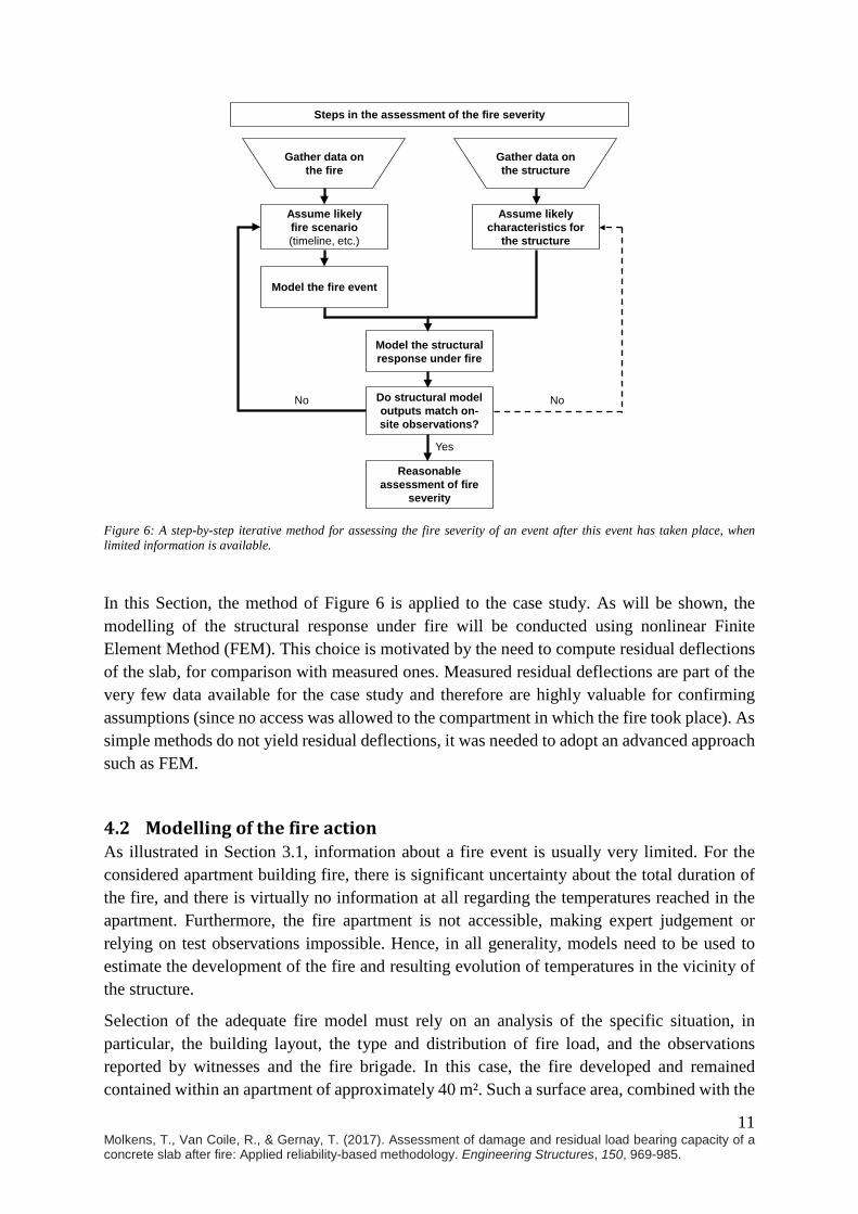
4.1 Methodology Step 1 in the assessment of the post-fire condition of the structure was the on-site inspection, including collection of data and information about the event. This has been exemplified above for the case study. The next step is the assessment of the fire severity, following the flowchart of Figure 1. This assessment can be done based on expert judgement, on-site tests (e.g. colour change of the concrete), models (e.g. numerical models), or a combination of these. In general, visual observations of the structural and non-structural damage resulting from the fire also inform about the fire severity. As the apartment where the fire occurred could not be accessed, a special assessment had to be performed, making the best possible use of the measured residual deflections and the information on the fire brigade intervention. Therefore, a method is proposed here for assessment of the fire severity following a fire event for which few information is available; this method is detailed in the flowchart of Figure 6.
The method starts by gathering data about the fire event and the characteristics of the structure. This data gathering results from the inspection done at the previous step (see Section 3 for the case study). Data about the structure should include section design (e.g. slab thickness and reinforcement) as well as structural system (support conditions) and loads. Based on the fire data, assumptions are made about the likely fire scenario, regarding elements such as the fire load involved, area of the fire, openings and, importantly, the timeline including the effect of intervention by the fire brigades (Figure 3). The data allows making informed assumptions but, being incomplete, it does not allow knowing with certainty what happened during the event. Modelling will therefore be used to refute or confirm the assumptions and reduce the uncertainty. The assumed fire scenario is simulated using modelling tools in order to obtain a temperature history in the compartment. This simulated temperature history can then be input in a structural model to simulate the effect of the fire on the structure. When an advanced method is employed for the structural simulation, the model yields detailed results which can be compared to on-site observations, for instance in terms of residual displacements. This comparison of residual structural damage between model and measurement brings an additional information that can be used to infer the fire severity. As a result, initial assumptions about the fire scenario can be adjusted in an iterative process, see Figure 6. Note that discrepancies between model outputs and measurements could also come from a wrong assumption on the characteristics of the structure (e.g. amount of reinforcement). However, in all generality, the uncertainty and the sensitivity is higher on the fire scenario than on structural characteristics, so that the iterations are preferably done on the fire side. The latter comment could however not hold true for some specific applications and should be verified in follow-up assessments (e.g. when access to the fire apartment is granted).
11 Molkens, T., Van Coile, R., & Gernay, T. (2017). Assessment of damage and residual load bearing capacity of a concrete slab after fire: Applied reliability-based methodology. Engineering Structures, 150, 969-985.
Figure 6: A step-by-step iterative method for assessing the fire severity of an event after this event has taken place, when limited information is available.
In this Section, the method of Figure 6 is applied to the case study. As will be shown, the modelling of the structural response under fire will be conducted using nonlinear Finite Element Method (FEM). This choice is motivated by the need to compute residual deflections of the slab, for comparison with measured ones. Measured residual deflections are part of the very few data available for the case study and therefore are highly valuable for confirming assumptions (since no access was allowed to the compartment in which the fire took place). As simple methods do not yield residual deflections, it was needed to adopt an advanced approach such as FEM.
4.2 Modelling of the fire action As illustrated in Section 3.1, information about a fire event is usually very limited. For the considered apartment building fire, there is significant uncertainty about the total duration of the fire, and there is virtually no information at all regarding the temperatures reached in the apartment. Furthermore, the fire apartment is not accessible, making expert judgement or relying on test observations impossible. Hence, in all generality, models need to be used to estimate the development of the fire and resulting evolution of temperatures in the vicinity of the structure.
Selection of the adequate fire model must rely on an analysis of the specific situation, in particular, the building layout, the type and distribution of fire load, and the observations reported by witnesses and the fire brigade. In this case, the fire developed and remained contained within an apartment of approximately 40 m². Such a surface area, combined with the
No
Steps in the assessment of the fire severity
Gather data on the fire
Gather data on the structure
Assume likelyfire scenario (timeline, etc.)
Assume likelycharacteristics for
the structure
Model the fire event
Model the structural response under fire
Do structural model outputs match on-site observations?
No
Yes
Reasonableassessment of fire
severity

12 Molkens, T., Van Coile, R., & Gernay, T. (2017). Assessment of damage and residual load bearing capacity of a concrete slab after fire: Applied reliability-based methodology. Engineering Structures, 150, 969-985.
fire load for a residential apartment (80% fractile characteristic fire load of 948 MJ/m² in accordance with EN 1991-1-2) and the observations from the fire fighters, all indicate a post-flashover compartment fire. Consequently, it was chosen to use the software OZone to model the fire (Cadorin, 2003). OZone is based on the resolution of mass conservation and energy conservation equations according to the zone model approach of EN 1991-1-2 (2002). It allows automatic transition from a two-zone fire to a one-zone (post-flashover) fire.
The thermal properties of the enclosure boundary materials used in the OZone model are listed in Table 2. The dimensions of the compartment were taken according to Figure 4, with a free height of 2.42 m. For the openings of the glass windows, a stepwise function was assumed, consisting in a 10% opening of the glass surface area at 20°C, a 50% opening at 200°C and 90% at 400°C. Table 2: Material properties of enclosure boundary materials, as used in the OZone model
Material Mass (kg/m³) λ (W/mK) c (-) t (m) Reference Ceiling 2300 1.6 1000 0.15 EN 1992-1-2
Wall 1600 0.7 840 0.14 & 0.19 EN 1996-1-2 Screed 1800 1.15 1000 0.08 EN 1992-1-2
OZone allows modelling a fully developed natural fire including the cooling down phase, which occurs when the fire runs short of fire load. However, in the case study the fire brigades arrived on site and started fighting the fire. It is assumed that this intervention caused the cooling down phase to start earlier than would have been the case according to the natural development of the fire. While it is not possible to know at which stage the fire was at the beginning of the fire brigade intervention, the possibility that the fire was in fact cut short due to this intervention needs to be considered.
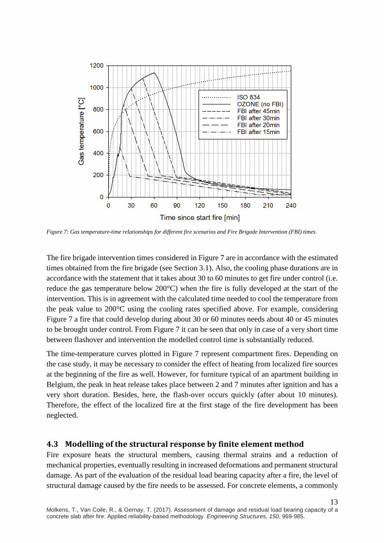
Figure 7 shows several possible gas temperature-time relationships for the case study. The curve labelled “OZONE (no FBI)” represents the temperature evolution obtained from the OZone analysis in which the Fire Brigade Intervention (FBI) is neglected, i.e. the fire develops fully until natural extinguishment. The other curves are obtained by adopting the same temperature-time relationship in the heating phase as the one obtained in the OZone analysis, but considering an earlier start of the cooling phase (i.e. descending branch) to model the effect of the fire brigade intervention. This descending branch has been chosen similar in shape and gradient as the descending branch in the full burnout simulation. Mathematically, this similar shape corresponds with an idealized tri-linear curve which changes cooling rate when the temperature reaches 200°C and 20°C. Hence, it is assumed that the intervention of the fire brigade speeds up the start of the tri-linear descending curve but does not affect the slope of the fire curves, conservatively neglecting the accelerated cooling associated with the water introduced by the fire brigade. As a reference for comparison, the ISO 834 standard fire curve is also plotted in Figure 7. The modelled descending branch has a gradient of -20.4°C per minute from the peak temperature up to a temperature of 200°C, and a gradient of 1.0°C per minute from 200°C up to the reference (constant) ambient temperature of 20°C. The applied formulation for the descending branch should only be considered applicable for this specific case.
13 Molkens, T., Van Coile, R., & Gernay, T. (2017). Assessment of damage and residual load bearing capacity of a concrete slab after fire: Applied reliability-based methodology. Engineering Structures, 150, 969-985.
Figure 7: Gas temperature-time relationships for different fire scenarios and Fire Brigade Intervention (FBI) times.
The fire brigade intervention times considered in Figure 7 are in accordance with the estimated times obtained from the fire brigade (see Section 3.1). Also, the cooling phase durations are in accordance with the statement that it takes about 30 to 60 minutes to get fire under control (i.e. reduce the gas temperature below 200°C) when the fire is fully developed at the start of the intervention. This is in agreement with the calculated time needed to cool the temperature from the peak value to 200°C using the cooling rates specified above. For example, considering Figure 7 a fire that could develop during about 30 or 60 minutes needs about 40 or 45 minutes to be brought under control. From Figure 7 it can be seen that only in case of a very short time between flashover and intervention the modelled control time is substantially reduced.
The time-temperature curves plotted in Figure 7 represent compartment fires. Depending on the case study, it may be necessary to consider the effect of heating from localized fire sources at the beginning of the fire as well. However, for furniture typical of an apartment building in Belgium, the peak in heat release takes place between 2 and 7 minutes after ignition and has a very short duration. Besides, here, the flash-over occurs quickly (after about 10 minutes). Therefore, the effect of the localized fire at the first stage of the fire development has been neglected.
4.3 Modelling of the structural response by finite element method Fire exposure heats the structural members, causing thermal strains and a reduction of mechanical properties, eventually resulting in increased deformations and permanent structural damage. As part of the evaluation of the residual load bearing capacity after a fire, the level of structural damage caused by the fire needs to be assessed. For concrete elements, a commonly
14 Molkens, T., Van Coile, R., & Gernay, T. (2017). Assessment of damage and residual load bearing capacity of a concrete slab after fire: Applied reliability-based methodology. Engineering Structures, 150, 969-985.
used indicator for the deterioration of the cross-section is the maximum section depth that has been affected by temperatures higher than 500°C. This simple indicator allows to use simplified and easily-understood analytical models, as will be discussed in Section 5.
However, more elaborate analyses of the structural response to fire exposure can be used to assess the structural damage and post-fire condition, and can be used to confirm the fire severity as well. The precise calculation of deflections for example allows a comparison with on-site observations of residual deformations. By conducting the structural analysis for a number of possible fire scenarios, a better estimation of the most likely fire scenario can be made.
When considering natural fire exposure and due to the level of complexity in the fire-response of common structures, advanced calculation methods such as numerical modelling are required for analysing the temperature distribution in the sections and evaluating the deflections. Illustrating the application of advanced numerical models to the case study, a structural analysis is made focusing on the concrete slab which is the ceiling of the apartment where the fire developed. It is a continuous slab supported by load bearing walls of masonry (hollow bricks of 19 cm). The analysis of the slab subjected to fire is conducted using the nonlinear finite element software SAFIR® developed at University of Liege (Franssen, 2005; Franssen and Gernay, 2017).
For the case study, no information about the structural design could be obtained. Therefore, the as-built design had to be estimated using the standard code NBN B15-103 (1977) in application at the time of the building construction. Boundary conditions are assumed to be simple vertical supports at the location of the joint or beams and clamping at the other supports. The loads applied on the slab are estimated according to Table 3. The concrete class is C30/37 and reinforcement strength fyk = 500 N/mm². Application of the old standard leads to a slab thickness of 150 mm with the following main reinforcement area: upper reinforcement of 598 mm²/m above supports and 258 mm²/m for balcony; lower reinforcement of 341 mm²/m in the principal direction and 141 mm²/m in the transverse direction. This structural design is deemed as the most likely given the information available; however it must be stressed that there is significant uncertainty on these values and that discrepancies in compression strength, reinforcement ratio or concrete cover can have an impact on the outcome of the analyses. In the ReAssess method, these parameters are taken as random parameters allowing to explicitly account for this uncertainty (see Section 5.3). As stated earlier however, the assessment can be improved by on-site inspection and tests once the fire compartment is accessible. Table 3: Loads acting on the slab
Load case Load (kN/m²) Reference Mobile load class A (Ψfi=0.30) 2.00 EN 1991-1-1 (2002) Partition walls < 3 kN/m 1.20 EN 1991-1-1 (2002) Screed of 80 mm LC 1.50 EN 1991-1-1 (2002) Dead load of 150 mm concrete 3.75 EN 1991-1-1 (2002)
The fire took place below the end span of the slab with a support consisting in a (double) wall of 14 cm. The area of the slab incorporated in the thermo-mechanical model consists in the boxed area of Figure 4.
15 Molkens, T., Van Coile, R., & Gernay, T. (2017). Assessment of damage and residual load bearing capacity of a concrete slab after fire: Applied reliability-based methodology. Engineering Structures, 150, 969-985.
Transient thermo-mechanical simulations are run using SAFIR®. Different fire exposures are successively considered, corresponding to the scenarios of Figure 7 (i.e. natural fire exposure based on OZone with different starting times for the cooling phase). The behaviour under the standard ISO fire is also computed for comparison purposes.
Thermal analyses are conducted first to get the temperature evolution across the slab thickness, for the different fire exposures. A siliceous concrete with a density of 2400 kg/m³ and a water content of 46 kg/m³ is assumed. The thermal properties of concrete in the heating phase were taken in accordance with Eurocodes: thermal conductivity taken as the average between the upper and lower limits (EN1992-1-2, 2005); coefficient of heat transfer by convection equal to 35 W/m²K (4 W/m²K on the unexposed side) (EN1991-1-2, 2002); and emissivity equal to 0.7 (EN1991-1-2, 2002). In cooling, the evolution of the properties is still under discussion, and there lacks a clear recommendation in the current version of the codes. Here, it was assumed that the specific mass of concrete, which decreases during heating because of the release of water, remains constant during cooling with a value that corresponds to the one of the maximum temperature. Similarly, it was considered that the decrease of thermal conductivity that is observed during heating is not reversible and, during cooling, the thermal conductivity of concrete keeps the value corresponding to the maximum temperature.
Structural analyses are then conducted taking into account the temperature in the slab obtained from the thermal analyses. The model is built using 642 shell finite elements. A plastic-damage model is used for modelling the concrete behaviour at elevated temperature (Gernay, 2013; Gernay, 2015). Transient creep strain is taken into account explicitly and is not recovered during cooling (Gernay and Franssen, 2012), which is of particular importance here since the comparison between the model and the real structure focuses on residual deflections. It is also assumed that, when concrete is back to ambient temperature, it exhibits a residual thermal expansion or shrinkage; the value of this residual thermal strain is a function of the maximum temperature and is taken from experimental tests published in the literature (Schneider, 1985). The concrete compressive and tensile strengths are taken as 30 MPa and 1 MPa, respectively. The temperature dependency of these strengths during heating is taken from EN1992-1-2. During cooling, an additional loss of 10 percent of the compressive strength has been considered compared to the value at maximum temperature (EN1994-1-2, 2005). The strain corresponding to the peak stress was considered during cooling as fixed to the value that prevailed at the maximum temperature (Felicetti et al., 2002). The other parameters in the concrete model are taken as: dilatancy parameter 0.25; compressive ductility parameter 0.19; compressive damage at peak stress 0.30; tensile ductility parameter 500 N/m². Steel reinforcing bars have a yield strength of 500 MPa. The mechanical properties of steel have been considered as reversible, which means that stiffness and strength are recovered to full initial values during cooling. Also, when steel is back to ambient temperature, it has no residual thermal expansion.
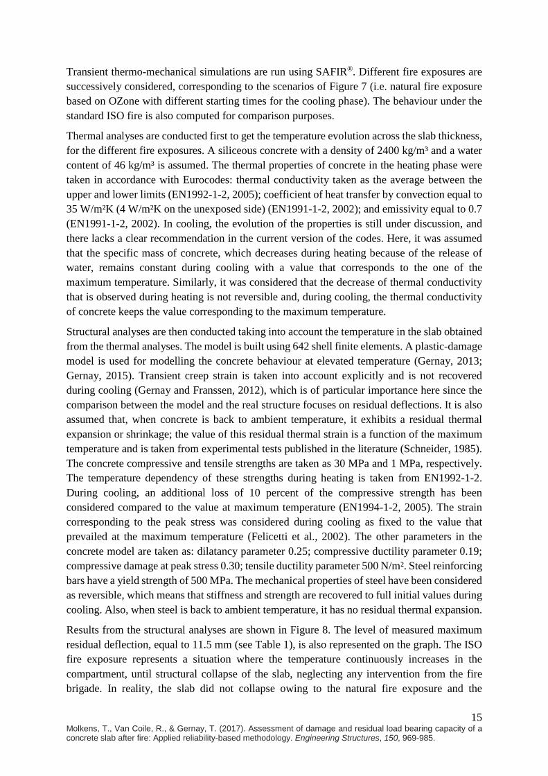
Results from the structural analyses are shown in Figure 8. The level of measured maximum residual deflection, equal to 11.5 mm (see Table 1), is also represented on the graph. The ISO fire exposure represents a situation where the temperature continuously increases in the compartment, until structural collapse of the slab, neglecting any intervention from the fire brigade. In reality, the slab did not collapse owing to the natural fire exposure and the
16 Molkens, T., Van Coile, R., & Gernay, T. (2017). Assessment of damage and residual load bearing capacity of a concrete slab after fire: Applied reliability-based methodology. Engineering Structures, 150, 969-985.
intervention of the fire brigade, which resulted in a decrease in the compartment temperature. Numerical analyses for the full course of the fire scenarios of Figure 7 (including the decay phase) show that, for natural fires with cut off between 20 min and 60 min, the vertical deflection of the slab increases up to a maximum deflection, then decreases and eventually exhibits a residual value. Considering the computed results of residual deflection, it is possible to estimate the fire scenario which most closely matches the measured deflections. Hence, the time of fire brigade intervention is estimated at approximately 30 minutes after ignition. This estimation is reasonably in line with the registered timeline of the event, see the time at which firefighting starts on Figure 3.
Figure 8: Evolution of vertical deflection of the slab at node 114 under the different fire scenarios of Figure 7 (FBI stands for Fire Brigade Intervention)
4.4 Comparison with on-site post-fire observations As discussed previously, the FEM model of the slab can reasonably explain the residual vertical deflection observed on site. Furthermore, it is estimated here whether the displacements experienced during the fire event can reasonably explain the cracking in the tiles that are observed in Figure 5.
FBI after 20 minFBI after 30 minFBI after 45 min
OZONE (no FBI)
ISO fire
-0,05
-0,04
-0,03
-0,02
-0,01
0,00
0 60 120 180 240 300 360
Def
lect
ion
[m]
Time [min]
node 114 (maximum deflection downward)
17 Molkens, T., Van Coile, R., & Gernay, T. (2017). Assessment of damage and residual load bearing capacity of a concrete slab after fire: Applied reliability-based methodology. Engineering Structures, 150, 969-985.
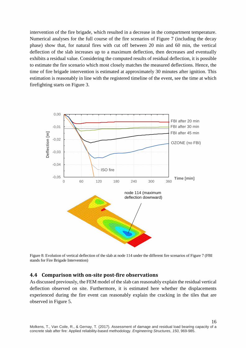
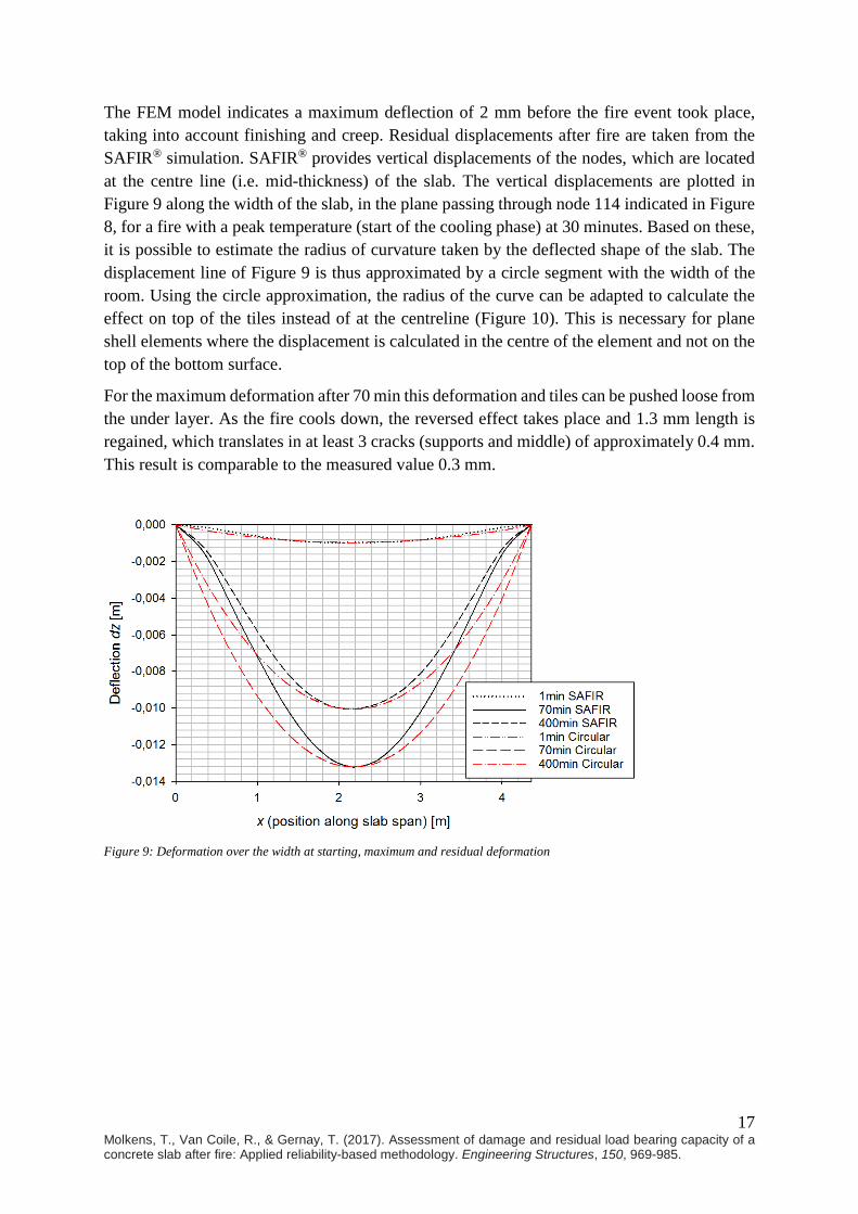
The FEM model indicates a maximum deflection of 2 mm before the fire event took place, taking into account finishing and creep. Residual displacements after fire are taken from the SAFIR® simulation. SAFIR® provides vertical displacements of the nodes, which are located at the centre line (i.e. mid-thickness) of the slab. The vertical displacements are plotted in Figure 9 along the width of the slab, in the plane passing through node 114 indicated in Figure 8, for a fire with a peak temperature (start of the cooling phase) at 30 minutes. Based on these, it is possible to estimate the radius of curvature taken by the deflected shape of the slab. The displacement line of Figure 9 is thus approximated by a circle segment with the width of the room. Using the circle approximation, the radius of the curve can be adapted to calculate the effect on top of the tiles instead of at the centreline (Figure 10). This is necessary for plane shell elements where the displacement is calculated in the centre of the element and not on the top of the bottom surface.
For the maximum deformation after 70 min this deformation and tiles can be pushed loose from the under layer. As the fire cools down, the reversed effect takes place and 1.3 mm length is regained, which translates in at least 3 cracks (supports and middle) of approximately 0.4 mm. This result is comparable to the measured value 0.3 mm.
Figure 9: Deformation over the width at starting, maximum and residual deformation
18 Molkens, T., Van Coile, R., & Gernay, T. (2017). Assessment of damage and residual load bearing capacity of a concrete slab after fire: Applied reliability-based methodology. Engineering Structures, 150, 969-985.
Figure 10: Deformation line of shell elements
4.5 Conclusion on the assessment of fire severity As shown, a step-by-step application of the method of Figure 6 allows improving the initial assumption on the fire severity. Iterations can be performed until the model outputs match the on-site measurements, thus informing on the fire event. For the case study, this method has provided valuable information about the most likely time of fire brigade intervention, based on residual deflection measurements and observed cracks. The fire can thus reasonably be estimated as the one obtained by an OZone analysis with a cut-off after 30 minutes due to the fire brigade intervention (“FBI after 30min” in Figure 7).
However, despite the agreement between model and measurements, it is clear that there remains uncertainty about the real fire severity, which could never be determined with complete certainty. Therefore, adopting one single deterministic fire would not reflect this fundamental lack of knowledge. In practice, it is not possible to determine the probability distribution of fire severity, but one simple approach consists in associating a probability to a few (discrete) different fire severities. This approach has the merit of acknowledging the uncertainty and accounting for some degree of variation, even if in a very simplified way for lack of better information. For the case study, it is decided to associate a probability of 0.60 to the fire with FBI at 30 minutes, and a probability of 0.20 to the fires with FBI at 20 minutes and 45 minutes, respectively. More advanced methodologies for model selection can be applied to improve the assessment (Burnham and Anderson, 2002).
The effect of the fire on the residual load bearing capacity of concrete elements can be linked to the depth penetration of the 500°C isotherm within the section. For the fires with FBI at 20 min, 30 min and 45 min, the maximum depth of the 500°C isotherm equals 5 mm, 14 mm and 22 mm, respectively. Adopting the above probabilities, the mean of the 500°C isotherm is found as 13.8 mm and the standard deviation is 5.4 mm. These values can then be used in the reliability-based post-fire assessment of load bearing capacity. Similarly, the probabilities associated with the different fire severities are incorporated in the evaluation of the residual reinforcement yield stress, see Section 5.
RSAFIR
Rtop surface
Dz,topDz,SAFIR
19 Molkens, T., Van Coile, R., & Gernay, T. (2017). Assessment of damage and residual load bearing capacity of a concrete slab after fire: Applied reliability-based methodology. Engineering Structures, 150, 969-985.
5 RELIABILITY-BASED POST-FIRE ASSESSMENT OF LOAD BEARING CAPACITY
5.1 Methodology A practical methodology for the reliability-based post-fire assessment of concrete elements has been presented in (Van Coile, 2015), improving the initial concepts and ideas introduced in (Van Coile et al., 2014). As discussed in Section 2, this reliability-based assessment methodology is denoted here as the ReAssess-method.
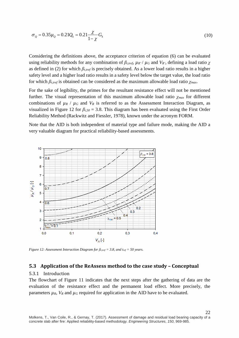
At its core, the method uses a pre-calculated diagram, called Assessment Interaction Diagram (AID), which depicts “interaction curves” for which an AID-specific target reliability index βt,tref as defined in Section 2.1 is precisely obtained. The interaction curves relate the expected value µR of the resistance effect and its coefficient of variation VR to values of the permanent load effect µG and the load ratio χ. Here, the load ratio is as defined by (2), with Qk the load effect induced by the imposed load, and Gk the load effect induced by the permanent load.
k
k k
QG Q
χ =+
(2)
The background of the AID is discussed in a separate section below, where Figure 12 visualizes the AID for βt,50 = 3.8.
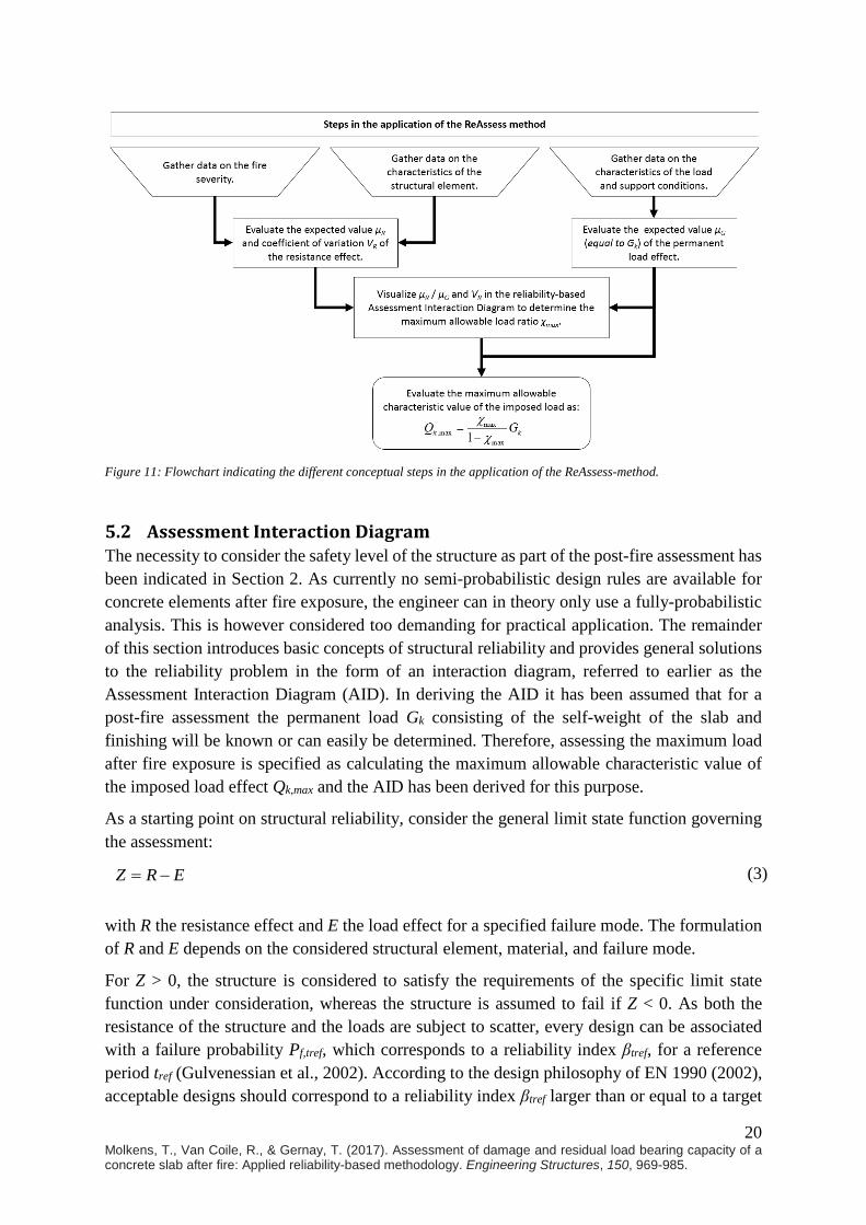
A conceptual flowchart describing the different steps of the ReAssess method is presented in Figure 11. Based on Figure 11, applying the ReAssess-method entails gathering data on the fire severity, structural element and permanent load effect, and using this data to evaluate the expected value µR of the resistance effect R and its coefficient of variation VR. By visualizing the obtained values in the Assessment Interaction Diagram (AID) and interpolating, the corresponding maximum allowable load ratio χmax is determined. The maximum allowable characteristic value of the imposed load is then directly given by (2) and the knowledge on the permanent load effect. Considering the above, the method easily allows to take into account data gained from inspections or tests. Furthermore, updated assessments can be made immediately as new information becomes available, allowing the method to be used both for a fast early assessment when little information is known and uncertainty is high, and for a detailed re-evaluation when test data, calculation results and expert judgements become available. In a first (and possibly only) iteration, the fire severity assessment will follow directly from the initial fire severity assessment of Step 2 in the global flowchart of Figure 1. In later iterations a re-evaluation of the fire severity may be considered. For example, colour evaluation of concrete cores can be used to directly evaluate the temperature ingress in the concrete element, as discussed in (Annerel, 2010).
20 Molkens, T., Van Coile, R., & Gernay, T. (2017). Assessment of damage and residual load bearing capacity of a concrete slab after fire: Applied reliability-based methodology. Engineering Structures, 150, 969-985.
Figure 11: Flowchart indicating the different conceptual steps in the application of the ReAssess-method.
5.2 Assessment Interaction Diagram The necessity to consider the safety level of the structure as part of the post-fire assessment has been indicated in Section 2. As currently no semi-probabilistic design rules are available for concrete elements after fire exposure, the engineer can in theory only use a fully-probabilistic analysis. This is however considered too demanding for practical application. The remainder of this section introduces basic concepts of structural reliability and provides general solutions to the reliability problem in the form of an interaction diagram, referred to earlier as the Assessment Interaction Diagram (AID). In deriving the AID it has been assumed that for a post-fire assessment the permanent load Gk consisting of the self-weight of the slab and finishing will be known or can easily be determined. Therefore, assessing the maximum load after fire exposure is specified as calculating the maximum allowable characteristic value of the imposed load effect Qk,max and the AID has been derived for this purpose.
As a starting point on structural reliability, consider the general limit state function governing the assessment:
Z R E= − (3) with R the resistance effect and E the load effect for a specified failure mode. The formulation of R and E depends on the considered structural element, material, and failure mode.
For Z > 0, the structure is considered to satisfy the requirements of the specific limit state function under consideration, whereas the structure is assumed to fail if Z < 0. As both the resistance of the structure and the loads are subject to scatter, every design can be associated with a failure probability Pf,tref, which corresponds to a reliability index βtref, for a reference period tref (Gulvenessian et al., 2002). According to the design philosophy of EN 1990 (2002), acceptable designs should correspond to a reliability index βtref larger than or equal to a target
21 Molkens, T., Van Coile, R., & Gernay, T. (2017). Assessment of damage and residual load bearing capacity of a concrete slab after fire: Applied reliability-based methodology. Engineering Structures, 150, 969-985.
reliability index βt,tref for the reference period considered. Through (1) this translates in a failure probability Pf,tref being smaller than a maximum allowable (target) failure probability.
[ ] [ ] ( ) ( ), ,0 0f tref tref t trefP P Z P R E β β= < = − < = Φ − ≤ Φ − (4)
where P[.] is the probability operator and Φ(.) the standardized cumulative normal distribution function.
Here, it is assumed that the target reliability index of 3.8 (50 year reference period) prescribed in EN 1990 for new structures with a design working life of 50 years and consequence class CC2 (moderate consequences of failure) applies as well for the safe continued use of the structure after fire exposure. The derivation of the AID is however generally applicable and a different AID can be generated easily if another target reliability index would be considered appropriate for the post-fire assessment.
For concrete structures in normal design conditions, the resistance effect R be described by a lognormal distribution, while the load effect E is a combination of the permanent load effect (normal distribution) and the imposed load effect (Gumbel distribution). Furthermore, lognormal model uncertainties KR and KE are considered, resulting in the general limit state function:
( )R EZ K R K G Q= − + (5)
Considering the definition of failure (Z < 0), (5) can be rewritten as (6) where the model uncertainties are mathematically combined in the “combined resistance effect” R’. As the model uncertainties are both described by a lognormal distribution, R’ is lognormal as well when assuming R to be lognormally distributed, as is commonly accepted for structural strength (Torrent, 1979).
( ) ( )
( ) ( ),
0 0
' 0
RR E
E
t tref
KP K R K G Q P R G QK
P R G Q β
− + < = − + <
= − + < ≤ Φ −
(6)
Based on the publication by Holický and Sýkora (2010), the mean and standard deviation of G and Q for a 50-year reference period can be related to their characteristic values Gk and Qk as specified in equations (7) to (10), where the load ratio χ is as defined earlier by (2).
G kµ G= (7)
0.1 0.1G G kµ Gσ = = (8)
0.6 0.61Q k kµ Q Gχ
χ= =
−
(9)
22 Molkens, T., Van Coile, R., & Gernay, T. (2017). Assessment of damage and residual load bearing capacity of a concrete slab after fire: Applied reliability-based methodology. Engineering Structures, 150, 969-985.
0.35 0.21 0.211Q Q k kµ Q Gχσ
χ= = =
−
(10)
Considering the definitions above, the acceptance criterion of equation (6) can be evaluated using reliability methods for any combination of βt,tref, µR’ / µG and VR’, defining a load ratio χ as defined in (2) for which βt,tref is precisely obtained. As a lower load ratio results in a higher safety level and a higher load ratio results in a safety level below the target value, the load ratio for which βt,tref is obtained can be considered as the maximum allowable load ratio χmax.
For the sake of legibility, the primes for the resultant resistance effect will not be mentioned further. The visual representation of this maximum allowable load ratio χmax for different combinations of µR / µG and VR is referred to as the Assessment Interaction Diagram, as visualized in Figure 12 for βt,50 = 3.8. This diagram has been evaluated using the First Order Reliability Method (Rackwitz and Fiessler, 1978), known under the acronym FORM.
Note that the AID is both independent of material type and failure mode, making the AID a very valuable diagram for practical reliability-based assessments.
Figure 12: Assessment Interaction Diagram for βt,tref = 3.8, and tref = 50 years.
5.3 Application of the ReAssess method to the case study – Conceptual 5.3.1 Introduction The flowchart of Figure 11 indicates that the next steps after the gathering of data are the evaluation of the resistance effect and the permanent load effect. More precisely, the parameters µR, VR and µG required for application in the AID have to be evaluated.

23 Molkens, T., Van Coile, R., & Gernay, T. (2017). Assessment of damage and residual load bearing capacity of a concrete slab after fire: Applied reliability-based methodology. Engineering Structures, 150, 969-985.
The ReAssess-method as presented originally in (Van Coile, 2015) uses analytical formulas to evaluate the mean value µR and coefficient of variation VR of the resistance effect. The use of analytical formulas has clear advantages with respect to ease-of-use, repeatability, and the possibility to immediately consider new information (e.g. results of inspections) when these becomes available. However, the analytical formulas given in (Van Coile, 2015) relate only to simply supported concrete slabs and beams subjected to positive (sagging) bending, and to axially compressed concrete columns, while the case study relates to the end span of a continuous concrete slab. The AID on the other hand is applicable to all types of elements, materials and limit states.
In the following section analytical formulas are elaborated applicable to the case study of the continuous concrete slab. Note that in a standard application of the ReAssess-method these analytical formulas are predetermined. Consequently, the following section is not part of a standard application of the method, but provides scientific background to applied formulas.
5.3.2 Derivation of analytical formulas The total load bearing capacity of the slab is made up of a contribution by the span moment capacity and the support (hogging) moment capacity. Based on the conceptual visualization in Figure 13 as adapted from Annex I of EN 1992-1-2 (2005) and considering deterministic (i.e. perfectly known) values for the hogging capacity MR,support and the uniformly distributed total load effect pE (including both permanent load and imposed load), the slab has sufficient load bearing capacity if the maximum sagging bending moment ME,span associated with ME(x) is smaller than the span bending moment capacity MR,span. Mathematically this corresponds with the conceptual failure limit state Z* of equation (11), with ME,span given by (12). The outer maximum operator acknowledges that the position x corresponding with the maximum sagging bending moment ME,span is not a priori known and depends on the realization of MR,support, while the inner maximum operator acknowledges that close to the continuous support, no resultant sagging moment is induced by the load effects due to the contribution of MR,support). For the evaluation of the limit state (11) however, this inner maximum is of no importance as a negative ME,span results in Z* > 0 and ‘no failure’. Therefore, the inner maximum operator is omitted further (although a negative ME,span can be considered to have no physical meaning). Note that for MR,support = 0, (11) and (12) result in the traditional bending failure definition Z* = MR,span – pE·l2/8.
*, ,R span E spanZ M M= − (11)
( ), ,supportmax max ;0
2E span E Rx
x l x xM p Ml
− = −
(12)

24 Molkens, T., Van Coile, R., & Gernay, T. (2017). Assessment of damage and residual load bearing capacity of a concrete slab after fire: Applied reliability-based methodology. Engineering Structures, 150, 969-985.
Figure 13: Concept bending capacity evaluation end span of continuous concrete slab.
Considering the above, the limit state (11) is written as (13). The maximum operator in (13) can be omitted by considering the limit state evaluation along the length x of the slab, resulting in the x-dependent limit state of equation (14). Without loss of generality, the contributions of MR,span and MR,support can be grouped in a combined resistance effect R*, resulting in a traditional separation of the load and resistance contributions in agreement with the derivations of the AID.
( )*, ,supportmax
2R span E Rx
x l x xZ M p Ml
− = − −
(13)
( ) ( )
( )
*, ,support
, ,support
* *
2
2
R span E R
R span R E
x l x xZ x M p Ml
x l xxM M pl
R E
−= − +
− = + −
= −
(14)
The above limit state (13) evaluates failure only at the ‘most critical point’ for the span bending moment, and consequently it is implicitly assumed that the top (support) reinforcement extends sufficiently long into the span of the slab. As the hogging demand decreases rapidly with the distance from the support and considering standard practice to extend reinforcement beyond the supports, this assumption is considered acceptable and not scrutinized further. This assumption can be confirmed during the on-site inspection in case on-site measurements of the reinforcement area and spacing are made.
Note that in the above equations model uncertainties have not been mentioned for clarity. These will be considered further in agreement with the AID derivations of Section 5.2.
As applied in (Van Coile, 2015), an analytical formulation for the residual span bending moment capacity MR,span is given by (15). This equation implicitly applies the 500°C limiting isotherm method, as accepted by EN 1992-1-2 for the assessment of the strength of concrete elements during fire exposure, and applied by Kodur et al. (2013) for the post-fire assessment of concrete columns. As discussed in (Van Coile, 2017) the limiting isotherm method gives an excellent approximation for the span residual bending moment capacity of concrete slabs. The choice of the limiting isotherm is however of no direct importance for the span residual bending moment capacity as the concrete which is severely heated acts in tension and the tensile strength of the concrete material is conservatively neglected. In the hypothetical case where
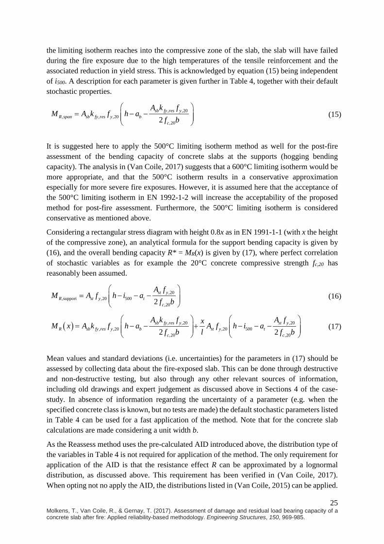
25 Molkens, T., Van Coile, R., & Gernay, T. (2017). Assessment of damage and residual load bearing capacity of a concrete slab after fire: Applied reliability-based methodology. Engineering Structures, 150, 969-985.
the limiting isotherm reaches into the compressive zone of the slab, the slab will have failed during the fire exposure due to the high temperatures of the tensile reinforcement and the associated reduction in yield stress. This is acknowledged by equation (15) being independent of i500. A description for each parameter is given further in Table 4, together with their default stochastic properties.
, ,20, , ,20
,202sb fy res y
R span sb fy res y bc
A k fM A k f h a
f b
= − −
(15)
It is suggested here to apply the 500°C limiting isotherm method as well for the post-fire assessment of the bending capacity of concrete slabs at the supports (hogging bending capacity). The analysis in (Van Coile, 2017) suggests that a 600°C limiting isotherm would be more appropriate, and that the 500°C isotherm results in a conservative approximation especially for more severe fire exposures. However, it is assumed here that the acceptance of the 500°C limiting isotherm in EN 1992-1-2 will increase the acceptability of the proposed method for post-fire assessment. Furthermore, the 500°C limiting isotherm is considered conservative as mentioned above.
Considering a rectangular stress diagram with height 0.8x as in EN 1991-1-1 (with x the height of the compressive zone), an analytical formula for the support bending capacity is given by (16), and the overall bending capacity R* = MR(x) is given by (17), where perfect correlation of stochastic variables as for example the 20°C concrete compressive strength fc,20 has reasonably been assumed.
,20,support ,20 500
,202st y
R st y tc
A fM A f h i a
f b
= − − −
(16)
( ) , ,20 ,20, ,20 ,20 500
,20 ,202 2sb fy res y st y
R sb fy res y b st y tc c
A k f A fxM x A k f h a A f h i af b l f b
= − − + − − −
(17)
Mean values and standard deviations (i.e. uncertainties) for the parameters in (17) should be assessed by collecting data about the fire-exposed slab. This can be done through destructive and non-destructive testing, but also through any other relevant sources of information, including old drawings and expert judgement as discussed above in Sections 4 of the case-study. In absence of information regarding the uncertainty of a parameter (e.g. when the specified concrete class is known, but no tests are made) the default stochastic parameters listed in Table 4 can be used for a fast application of the method. Note that for the concrete slab calculations are made considering a unit width b.
As the Reassess method uses the pre-calculated AID introduced above, the distribution type of the variables in Table 4 is not required for application of the method. The only requirement for application of the AID is that the resistance effect R can be approximated by a lognormal distribution, as discussed above. This requirement has been verified in (Van Coile, 2017). When opting not no apply the AID, the distributions listed in (Van Coile, 2015) can be applied.
26 Molkens, T., Van Coile, R., & Gernay, T. (2017). Assessment of damage and residual load bearing capacity of a concrete slab after fire: Applied reliability-based methodology. Engineering Structures, 150, 969-985.
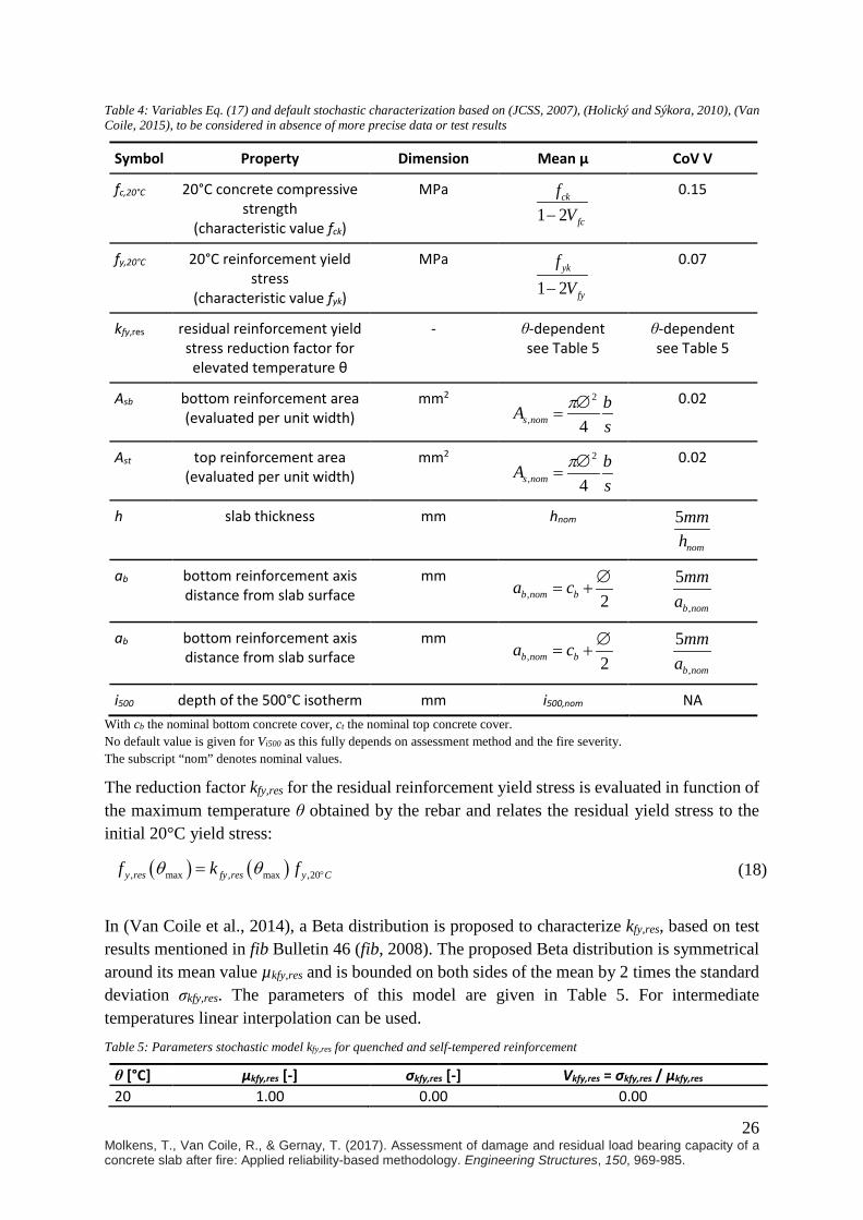
Table 4: Variables Eq. (17) and default stochastic characterization based on (JCSS, 2007), (Holický and Sýkora, 2010), (Van Coile, 2015), to be considered in absence of more precise data or test results
Symbol Property Dimension Mean µ CoV V
fc,20°C
20°C concrete compressive strength
(characteristic value fck)
MPa
1 2ck
fc
fV−
0.15
fy,20°C 20°C reinforcement yield stress
(characteristic value fyk)
MPa
1 2yk
fy
fV−
0.07
kfy,res residual reinforcement yield stress reduction factor for elevated temperature θ
- θ-dependent see Table 5
θ-dependent see Table 5
Asb bottom reinforcement area (evaluated per unit width)
mm2 2
, 4s nombAs
π∅=
0.02
Ast top reinforcement area (evaluated per unit width)
mm2 2
, 4s nombAs
π∅=
0.02
h slab thickness mm hnom 5
nom
mmh
ab bottom reinforcement axis distance from slab surface
mm , 2b nom ba c ∅
= + ,
5
b nom
mma
ab bottom reinforcement axis distance from slab surface
mm , 2b nom ba c ∅
= + ,
5
b nom
mma
i500 depth of the 500°C isotherm mm i500,nom NA With cb the nominal bottom concrete cover, ct the nominal top concrete cover. No default value is given for Vi500 as this fully depends on assessment method and the fire severity. The subscript “nom” denotes nominal values.
The reduction factor kfy,res for the residual reinforcement yield stress is evaluated in function of the maximum temperature θ obtained by the rebar and relates the residual yield stress to the initial 20°C yield stress:
( ) ( ), max , max ,20y res fy res y Cf k fθ θ °= (18)
In (Van Coile et al., 2014), a Beta distribution is proposed to characterize kfy,res, based on test results mentioned in fib Bulletin 46 (fib, 2008). The proposed Beta distribution is symmetrical around its mean value µkfy,res and is bounded on both sides of the mean by 2 times the standard deviation σkfy,res. The parameters of this model are given in Table 5. For intermediate temperatures linear interpolation can be used. Table 5: Parameters stochastic model kfy,res for quenched and self-tempered reinforcement
θ [°C] µkfy,res [-] σkfy,res [-] Vkfy,res = σkfy,res / µkfy,res
20 1.00 0.00 0.00

27 Molkens, T., Van Coile, R., & Gernay, T. (2017). Assessment of damage and residual load bearing capacity of a concrete slab after fire: Applied reliability-based methodology. Engineering Structures, 150, 969-985.
50 1.00 0.00 0.00 100 1.00 0.05 0.05 200 1.00 0.05 0.05 400 1.00 0.05 0.05 550 1.00 0.05 0.05 600 1.00 0.05 0.05 700 0.70 0.07 0.10 850 0.60 0.10 0.17
The application of the limiting isotherm method in Eq. (17) however neglects the nonlinear distribution of maximum temperatures in the slab cross-section. Based on (Van Coile, 2017), the error introduced by this simplification can be corrected for the span bending moment capacity by dividing MR,span by a lognormal model uncertainty KM with mean value 1.004 and coefficient of variation 0.003, and for the hogging bending moment by a lognormal model uncertainty with mean 0.95 and coefficient of variation 0.02. Note that the mean value of 0.95 is illustrative of the conservativeness of the 500°C limiting isotherm. Based on the above, a conservative overall KM model is applied further with mean 1.0 and coefficient of variation 0.02.
As indicated in (6), the Assessment Interaction Diagram is based on incorporating all model uncertainties as part of the resistance effect R. Consequently, R is given by (19) with MR as defined by (17) and the model uncertainties as specified in Table 6. As all model uncertainties are lognormal, they can be combined analytically in the single total model uncertainty KT.
RR T R
E M
KR M K MK K
= =
(19)
Table 6: Probabilistic models for the model uncertainties
Symbol Property Mean µ CoV V
KR Model uncertainty for the resistance effect (bending) 1.1 0.1
KE Model uncertainty for the load effect (bending) 1.0 0.1
KM Model uncertainty accounting for the simplifications introduced. 1.0 0.02
KT Total model uncertainty. 1.1 0.14
Having determined an analytical formula for R, the mean value µR and coefficient of variation VR of the resistance effect R must be assessed for application of the ReAssess-method as described in the flowchart of Figure 11. As in (Van Coile et al., 2014) both parameters can be assessed by a first-order Taylor approximation see (20)-(22) where µ is the vector with the mean values for all the parameters Xi (e.g. mean value µh for the slab thickness h).
( )Rµ R≈ µ (20)
28 Molkens, T., Van Coile, R., & Gernay, T. (2017). Assessment of damage and residual load bearing capacity of a concrete slab after fire: Applied reliability-based methodology. Engineering Structures, 150, 969-985.
( ) 22
R Xi ii ii
RS
Xσ σ
∂ ≈ = ∂ ∑ ∑
µ
(21)
RR
R
Vµσ
=
(22)
The constituents Si are the contributions of the different uncertain variables to the overall uncertainty. For example, the contribution SAsb of the bottom reinforcement area is given by (23) and the contribution SKT of the total model uncertainty is given by (24).
( )22 2
, ,20 2, ,20
,20
Asb kfy res fyAsb KT kfy res fy h ab KT Asb
fc
µ µ µS µ µ µ µ µ µ
µ bσ
= − −
(23)
2
, ,20, ,20
,20 2
,20,20 500
,20
2
2
Asb kfy res fyAsb kfy res fy h ab
fc
KT KT
Ast fyAst fy h i at
fc
µ µ µµ µ µ µ µ
µ bS
µ µx µ µ µ µ µl µ b
σ
− − =
+ − − −
(24)
Note that for a standard application of the method in accordance with a standard or guidance document, KT would have been predetermined and the values of its parameters µKT and σKT could have been inserted directly into equations (20)-(22) if it is considered beneficial to avoid complicating the application with a discussion on KT.
5.4 Application of the ReAssess method to the case study – Detailed 5.4.1 Gather data on the fire severity, slab characteristics and the permanent load effect This has been discussed in Section 4. As limited information is available regarding the uncertainty on the input variables, the default models of Table 6 will be applied where necessary.
As Section 4 concluded with assigning a 20% probability of the 20 min FBI (fire brigade intervention) fire, 60% probability to 30 min FBI and 20% probability to 45 min FBI, the mean value and standard deviation of i500 have been evaluated directly in Section 4 by implicitly applying equations (25) and (26), with i500,FS the depth of the 500°C isotherm for a given fire scenario FS and pFS the probability associated with this scenario. This resulted in µi500 = 13.8mm and σi500 = 5.4mm. Equation (25) and (26) are applicable when no uncertainty is associated with i500,FS as assessed for a given fire scenario (i.e. i500,FS is deterministic). Specifically for the case study, the numerical evaluation of the temperature ingress in the slab for a given fire scenario has been considered deterministic and all associated uncertainty is considered to be incorporated through the probabilities assigned to the different fire scenarios.
500 500,i FS FSFS
µ i p=∑ (25)

29 Molkens, T., Van Coile, R., & Gernay, T. (2017). Assessment of damage and residual load bearing capacity of a concrete slab after fire: Applied reliability-based methodology. Engineering Structures, 150, 969-985.
( )2500 500 500,i i FS FS
FSµ i pσ = −∑
(26)
For the reinforcement residual yield stress reduction factor kfy,res, an assessment is made considering (27) and (28), where pθmax is the probability of the reinforcement reaching a given maximum temperature θmax as a result of the fire exposure. Note that the term σkfy,res relates to the uncertainty regarding the reduction factor kfy,res for a known maximum temperature θmax, see Table 5. The use of pθmax in equations (27) and (28) acknowledges not only the uncertainty with respect to the fire scenario, but also the uncertainty with respect to the axis position of the reinforcement ab. Considering the stochastic model for ab incorporated in Table 6 and using the discretization proposed in (Van Coile, 2015), the reinforcement temperature is determined for each fire scenario for each of the 6 locations listed in Table 7. Each location has an associated probability (corresponding with a discretization of the model listed in Table 5). By evaluating kfy,res and σkfy,res for each of the 6 listed positions and for each fire scenario, and by considering pθmax = pFS · pai, equations (27) and (28) are evaluated as 0.999 and 0.0512.
( )max
, , max θmaxkfy res fy resµ k pθ
θ= ∑ (27)
( )( ) ( )max max
2 2, , max , θmax , max θmaxkfy res fy res kfy res kfy resk µ p p
θ θ
σ θ σ θ= − +∑ ∑
(28)
Table 7: Discrete positions ai for the reinforcement axis positions and associated probabilities pai.
ai [mm] Probability pai
µab – 2.5σab 0.02 µab – 1. 5σab 0.15 µab – 0. 5σab 0.33 µab + 0. 5σab 0.33 µab + 1. 5σab 0.15 µab + 2. 5σab 0.02
5.4.2 Calculate the parameters µR and VR of the resistance effect R The information obtained from the inspection and numerical assessment is used to make an assessment of the mean µR and coefficient of variation VR of the combined resistance effect R defined by (19), through equations (20)-(22). As not all parameters have been assessed directly through tests or calculations, the default parameters listed in Table 4 are used to supplement the data. An overview of all variables and their values is given in Table 8. Table 8: Variables and applied values
Symbol Property Dim. Mean µ CoV V Standard Deviation σ
fc,20°C (fck = 30 Mpa)
20°C concrete compressive strength MPa 42.9 0.15 6.4
fy,20°C 20°C reinforcement yield stress MPa 581.4 0.07 40.7

30 Molkens, T., Van Coile, R., & Gernay, T. (2017). Assessment of damage and residual load bearing capacity of a concrete slab after fire: Applied reliability-based methodology. Engineering Structures, 150, 969-985.
(fyk = 500 Mpa)
kfy,res residual reinforcement yield stress reduction factor at elevated
temperature θ
- 1.0 0.05 0.05
Asb bottom reinforcement area (evaluated per unit width)
mm2 223 0.02 4.5
Ast top reinforcement area (evaluated per unit width)
mm2 692 0.02 13.8
h slab thickness mm 150 0.03 5
ab bottom reinforcement axis distance from slab surface
mm 25 0.2 5
at top reinforcement axis distance from slab surface
mm 25 0.2 5
i500 depth of the 500°C isotherm mm 13.8 0.4 5.4
KT total model uncertainty - 1.11 0.14 0.15
gk characteristic value of the uniformly distributed permanent load
kN/m2 5 - -
l length of the span m 4.44 - -
In accordance with equation (17) and the discussion in Section 5.3, both the resistance effect and the load effect are x-dependent (see Figure 13), with the most critical location not known a priori. For MR,support close to zero the most critical location will be mid-span at x = l/2. For MR,support > 0, the most critical location will be closer to the pinned support, i.e. closer to x = 0. In order to illustrate this, the evaluation of µR / µG and VR is done for x ranging from 0 to l/2. Results are as visualized in Figure 14. Note that µG has been evaluated directly as gk·x·(l-x)/2, see Section 5.3.2.
In principle every point on Figure 14 (i.e. every cross-section along (half) the span of the slab as indicated in Figure 13) corresponds with a maximum allowable load ratio χmax,x when implementing the values of μR / μG and VR in the AID of Figure 12. The most critical point (lowest χmax,x) then defines the overall capacity of the slab. Investigating Figure 14, it is observed that the coefficient of variation VR is quasi-constant at a value of 0.17, while the ratio µR /µG rises asymptotically for small values of x/l close to 0. The most critical location is found for x/l = 0.34 with µR /µG = 3.07 and VR = 0.17. Note that close to the pinned support (x = 0) the slightly higher value of VR as more than offset by the increase of µR /µG, as can easily be verified by implementing an example point in the AID of Figure 12 and observing a much higher value of χmax (e.g. VR = 0.173 and µR /µG = 9.5 for x/l = 0.04).
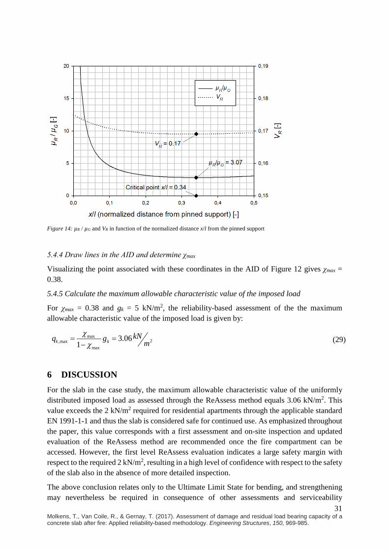
31 Molkens, T., Van Coile, R., & Gernay, T. (2017). Assessment of damage and residual load bearing capacity of a concrete slab after fire: Applied reliability-based methodology. Engineering Structures, 150, 969-985.
Figure 14: µR / µG and VR in function of the normalized distance x/l from the pinned support
5.4.4 Draw lines in the AID and determine χmax
Visualizing the point associated with these coordinates in the AID of Figure 12 gives χmax = 0.38.
5.4.5 Calculate the maximum allowable characteristic value of the imposed load
For χmax = 0.38 and gk = 5 kN/m2, the reliability-based assessment of the the maximum allowable characteristic value of the imposed load is given by:
max2,max
max
3.061k k
kNq g mχχ
= =−
(29)
6 DISCUSSION For the slab in the case study, the maximum allowable characteristic value of the uniformly distributed imposed load as assessed through the ReAssess method equals 3.06 kN/m2. This value exceeds the 2 kN/m2 required for residential apartments through the applicable standard EN 1991-1-1 and thus the slab is considered safe for continued use. As emphasized throughout the paper, this value corresponds with a first assessment and on-site inspection and updated evaluation of the ReAssess method are recommended once the fire compartment can be accessed. However, the first level ReAssess evaluation indicates a large safety margin with respect to the required 2 kN/m2, resulting in a high level of confidence with respect to the safety of the slab also in the absence of more detailed inspection.
The above conclusion relates only to the Ultimate Limit State for bending, and strengthening may nevertheless be required in consequence of other assessments and serviceability
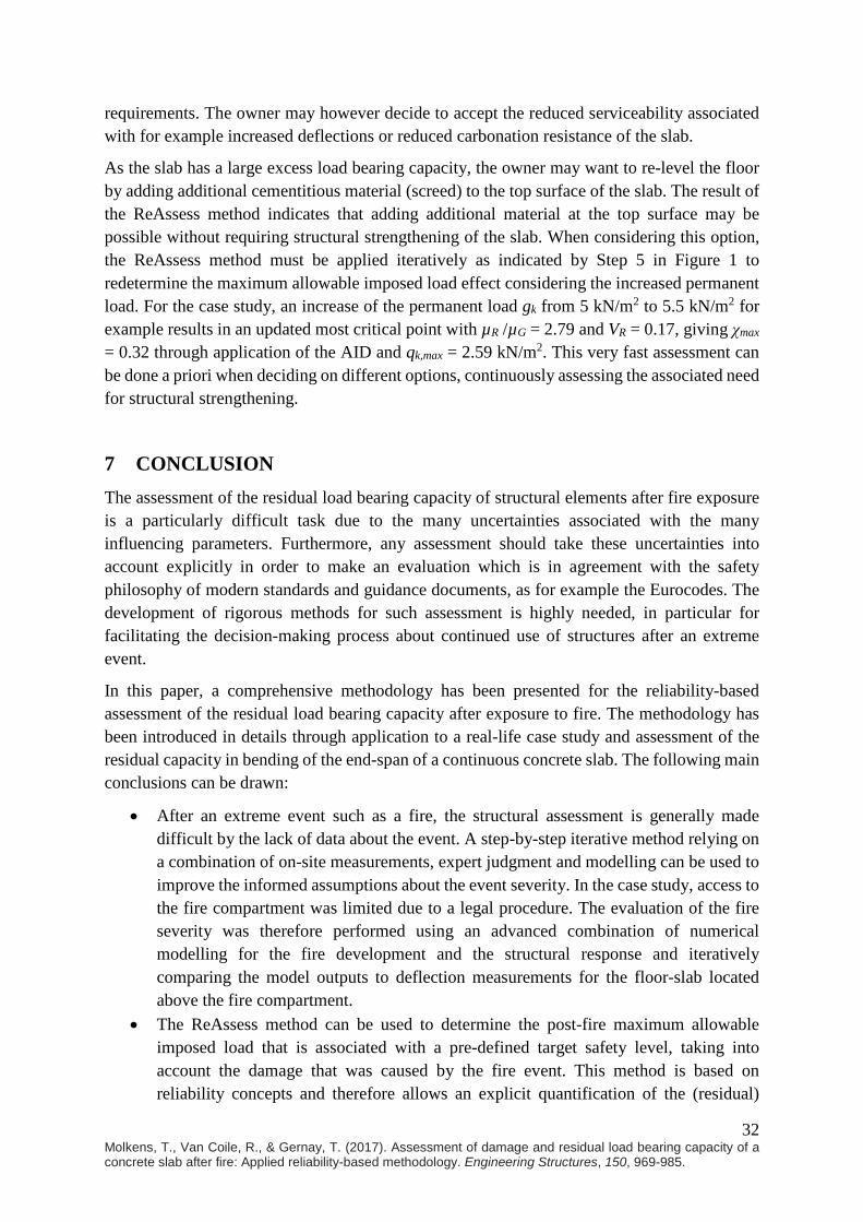
32 Molkens, T., Van Coile, R., & Gernay, T. (2017). Assessment of damage and residual load bearing capacity of a concrete slab after fire: Applied reliability-based methodology. Engineering Structures, 150, 969-985.
requirements. The owner may however decide to accept the reduced serviceability associated with for example increased deflections or reduced carbonation resistance of the slab.
As the slab has a large excess load bearing capacity, the owner may want to re-level the floor by adding additional cementitious material (screed) to the top surface of the slab. The result of the ReAssess method indicates that adding additional material at the top surface may be possible without requiring structural strengthening of the slab. When considering this option, the ReAssess method must be applied iteratively as indicated by Step 5 in Figure 1 to redetermine the maximum allowable imposed load effect considering the increased permanent load. For the case study, an increase of the permanent load gk from 5 kN/m2 to 5.5 kN/m2 for example results in an updated most critical point with µR /µG = 2.79 and VR = 0.17, giving χmax = 0.32 through application of the AID and qk,max = 2.59 kN/m2. This very fast assessment can be done a priori when deciding on different options, continuously assessing the associated need for structural strengthening.
7 CONCLUSION The assessment of the residual load bearing capacity of structural elements after fire exposure is a particularly difficult task due to the many uncertainties associated with the many influencing parameters. Furthermore, any assessment should take these uncertainties into account explicitly in order to make an evaluation which is in agreement with the safety philosophy of modern standards and guidance documents, as for example the Eurocodes. The development of rigorous methods for such assessment is highly needed, in particular for facilitating the decision-making process about continued use of structures after an extreme event.
In this paper, a comprehensive methodology has been presented for the reliability-based assessment of the residual load bearing capacity after exposure to fire. The methodology has been introduced in details through application to a real-life case study and assessment of the residual capacity in bending of the end-span of a continuous concrete slab. The following main conclusions can be drawn:
• After an extreme event such as a fire, the structural assessment is generally made difficult by the lack of data about the event. A step-by-step iterative method relying on a combination of on-site measurements, expert judgment and modelling can be used to improve the informed assumptions about the event severity. In the case study, access to the fire compartment was limited due to a legal procedure. The evaluation of the fire severity was therefore performed using an advanced combination of numerical modelling for the fire development and the structural response and iteratively comparing the model outputs to deflection measurements for the floor-slab located above the fire compartment.
• The ReAssess method can be used to determine the post-fire maximum allowable imposed load that is associated with a pre-defined target safety level, taking into account the damage that was caused by the fire event. This method is based on reliability concepts and therefore allows an explicit quantification of the (residual)
33 Molkens, T., Van Coile, R., & Gernay, T. (2017). Assessment of damage and residual load bearing capacity of a concrete slab after fire: Applied reliability-based methodology. Engineering Structures, 150, 969-985.
safety level. The actual reliability-based assessment is done through a pre-calculated diagram (called the Assessment Interaction Diagram or AID) and simple analytical formulas, allowing for fast and easily-understood real-time assessments of the maximum allowable characteristic value of the imposed load.
• The methodology presented in the paper encompasses all the different steps from the on-site inspection after the event to the reliability evaluation of the residual capacity. In the end, it allows making an informed decision regarding the continued use of the structure. It is also possible to assess the effect of strengthening or repair strategies on the safety level.
• It must be stressed that this work focuses on ultimate capacity only, disregarding serviceability aspects. Dependent on the requirements of the owner, the decision about the need for an intervention after an event should also take into account serviceability considerations such as residual deflections.
REFERENCES
Annerel, E. (2010). Assessment of the residual strength of concrete structures after fire exposure. Doctoral dissertation, Ghent University, Belgium.
Bocchini, P., Asce, M., Frangopol, D. M., Asce, D. M., Ummenhofer, T., & Zinke, T. (2014). Resilience and Sustainability of Civil Infrastructure : Toward a Unified Approach. Journal of Infrastructure Systems, 20(2), 1–16. doi:10.1061/(ASCE)IS.1943-555X.0000177.
Burnham, K.P., Anderson, D.R. (2002). Model selection and multimodel inference: a practical information-theoretic approach. Springer. New York.
Cadorin J.-F. & Franssen J.-M., “A tool to design steel elements submitted to compartment fires OZone V2. Part 1: pre- and post-flashover compartment fire model”, Fire Safety Journal, Elsevier, 38 (2003), 395-427, <http://hdl.handle.net/2268/29650>
Chen, Y.-H., Chang, Y.-F., Yao, G.C., Sheu, M.-S. (2009). Experimental research on post-fire behavior of reinforced concrete columns. Fire Safety Journal, 44, 741-748.
El-Hawary, M.M., Ragab, A.M., Abd El-Azim, A., Elibiari, S. (1996). Effect of fire on flexural behavior of RC beams. Construction and Building Materials, 10(2), 147-150.
EN 1990 (2002). “Eurocode 0: Basis of structural design”. European Committee for Standardization CEN.
EN 1991-1-1 (2002). “Eurocode 1: Actions on structures - Part 1-2: General actions – Densities, self-weight, imposed loads for buildings”. European Committee for Standardization CEN.
EN 1991-1-2 (2002). “Eurocode 1: Actions on structures - Part 1-2: General actions – Actions on structures exposed to fire”, European Committee for Standardization CEN.
34 Molkens, T., Van Coile, R., & Gernay, T. (2017). Assessment of damage and residual load bearing capacity of a concrete slab after fire: Applied reliability-based methodology. Engineering Structures, 150, 969-985.
EN 1992-1-2 (2005). “Eurocode 2: Design of concrete structures - Part 1-2: General rules - Structural fire design”, European Committee for Standardization CEN.
EN 1994-1-2 (2005). “Eurocode 4: Design of composite steel and concrete structures - Part 1-2: General rules - Structural fire design”, European Committee for Standardization CEN.
EN 1996-1-2 (2005). “Eurocode 6: Design of masonry structures - Part 1-2: General rules - Structural fire design”, European Committee for Standardization CEN.
EU. (2011). Regulation No 305/2011 of the European Parliament and of the Council of 9 March 2011 laying down harmonised conditions for the marketing of construction products and repealing Council Directive 89/106/EEC. Official Journal of the European Union, 54 (L88), 5-43.
Felicetti, R., Gambarova, P.G., Silva, M. and Vimercati, M. (2002), “Thermal diffusivity and residual strength of high-performance light-weight concrete exposed to high temperature”, 6th Int. Symp. on Utilization of HSC/HPC, Leipzig, pp. 935-948.
Franssen, J.-M., Gernay, T. (2017) “Modeling Structures in Fire with SAFIR®: Theoretical Background and Capabilities”, Journal of Structural Fire Engineering, https://doi.org/10.1108/JSFE-07-2016-0010.
Franssen, J.M. (2005). “SAFIR. A Thermal/Structural Program Modelling Structures under Fire”, Engineering Journal, A.I.S.C., Vol 42, No. 3, 143-158.
Gernay, T. and Franssen, J.-M. (2012), “A formulation of the Eurocode 2 concrete model at elevated temperature that includes an explicit term for transient creep”, Fire Safety Journal, Vol. 51, pp. 1-9.
Gernay, T., Millard, A., Franssen, J.-M. (2013). A multiaxial constitutive model for concrete in the fire situation: Theoretical formulation. Int J Solids Struct, 50(22-23): 3659-3673. Gernay, T., Franssen, J.-M. (2015). A plastic-damage model for concrete in fire: Applications in structural fire engineering. Fire Safety J, 71: 268–278. Gulvanessian, H. Calgaro, J.-A., Holický, M. (2002). Designer’s guide to EN 1990: Eurocode 0: Basis for structural design. Thomas Telford, London. Holický, M., Sýkora, M. (2010). Stochastic models in analysis of structural reliability. Proceedings of the International Symposium on Stochastic Models in Reliability Engineering, Life Sciences and Operation Management. 08-11/02, Beer Sheva, Israel.
Ioannou, I., Aspinall, W., Rush, D., Bisby, L., Rossetto, T. (2017). Expert judgment-based fragility assessment of reinforced concrete buildings exposed to fire. Reliability Engineering and System Safety, 167, 105-127.
Jau, W-C., Huang, K-L. (2008). A study of reinforced concrete corner columns after fire. Cement & Concrete Composites, 30, 622-638.
JCSS. (2007). Probabilistic Model Code. The Joint Committee on Structural Safety. Available online at www.jcss.byg.dtu.dk
35 Molkens, T., Van Coile, R., & Gernay, T. (2017). Assessment of damage and residual load bearing capacity of a concrete slab after fire: Applied reliability-based methodology. Engineering Structures, 150, 969-985.
Kodur, V.K.R., Raut, N.K., Mao, X.Y., Khaliq, W. (2013). Simplified approach for evaluating residual strength of fire-exposed reinforced concrete columns. Materials and Structures, 46, 2059-2075.
Kodur, V.K.R., Agrawal, A. (2016). An approach for evaluating residual capacity of reinforced concrete beams exposed to fire. Engineering Structures, 110, 293-306.
Lange, D., Devaney, S., Usmani, A. (2014). An application of the PEER PBEE framework to structures in fire. Engineering Structures, 66, 100-115.
Mostafaei, H., et al. (2014). Resilience of critical infrastructure to extreme fires – Gaps and challenges. Report DRDC-RDDC-2014-C66, NRC, Canada, 73p.
NBN B15-103. (1977). Design of reinforced concrete. Belgian Institute for Standards BIN.
Rackwitz, R., Fiessler, B. (1978). Structural reliability under combined random load sequences. Computers & Structures, 9(5), 489-494.
Raouffard, M.M., Nishiyama, M. (2016). Residual Load Bearing Capacity of Reinforced Concrete Frames after Fire. Journal of Advanced Concrete Technology, 14, 625-633.
Schneider, U. (1985). Properties of Materials at High Temperatures: Concrete, RILEM, Univ. of Kassel, Kassel (edited by U. Schneider).
Spinardi, G., Bisby, L., Torero, J. (2017). A review of Sociological Issues in Fire Safety Regulation. Fire Technology, 53, 1011-1037.
Van Coile, R., Caspeele, R., Taerwe, L. (2014). Towards a reliability-based post-fire assessment method for concrete slabs incorporating data from inspection. Structural Concrete, 15(3), 395-407.
Van Coile, R. (2015). Reliability-based decision making for concrete elements exposed to fire. Doctoral dissertation. Ghent University, Belgium.
Van Coile, R., Caspeele, R., Taerwe, L. (2015). Post-fire safety of concrete columns: An engineering-oriented reliability-based assessment tool. Proceedings of Applications of Structural Fire Engineering (ASFE 2015). 15-16/10, Dubrovnik, Croatia.
Van Coile, R. (2017) Post-fire residual bending capacity for concrete slabs: probabilistic evaluation, limiting isotherm and stochastic correction factor. In preparation.