assessment of epoxy resins for injected bolted shear
TRANSCRIPT
i
Assessment of Epoxy Resins for
Injected Bolted Shear Connections Axel Koper


Assessment of Epoxy Resins for Injected
Bolted Shear Connections An experimental research on double lap shear connections with injected bolts
A.M. Koper
To obtain the degree of Master of Science in Civil Engineering
at the Delft University of Technology
To be defended publicly on Tuesday May 30th, 2017 at 9:00 AM.
Student number: 4092120
Committee: Prof. dr. M. Veljkovic TU Delft supervisor
Ir. P.A. de Vries TU Delft
Dr. O. Çopuroğlu, TU Delft
Drs. W.F. Gard TU Delft


Assessment of epoxy resins for injected bolted shear connections v
1 Preface This thesis is submitted for the requirements of the Structural Engineering master track at the Faculty of
Civil Engineering and Geo Sciences of the Delft University of Technology. The topic of the thesis is an
investigation into resin products for application in injected bolted connections in civil engineering steel
structures. The research is mainly focused on alternative resin in a double lap shear application.
I started to work on this thesis in 2016 mainly focusing on investigating the admittedly limited research
base of the topic of resin applications in civil engineering practice. Throughout the year, I have tested
resins in the Stevin Laboratory of TU Delft. For this I would like to express my gratitude to the lab staff
and more specifically J. Hermsen and F.J.P. Schilperoort for helping me to perform the tests in the Stevin
Laboratory.
Also, I would of course like to extend my gratitude towards the members of my assessment committee,
Prof. dr. M. Veljkovic, ir. P.A. de Vries, Drs. W.F. Gard and in particular dr. Çopuroğlu for joining my
committee at a later stage.
Furthermore, I would like to thank G. van Bolderen, M. Mureau, C. Hagen and C.A. van Hoogdalem.
Working on my thesis in parallel with them in the Office of Stevin II 1.34 has given me a lot of support.
Of course, I also want to thank my parents for supporting me during this thesis but also throughout my
time as a student at the TU Delft.
Axel Koper
Delft, May 2017

vi Assessment of epoxy resins for injected bolted shear connections

Assessment of epoxy resins for injected bolted shear connections vii
2 Abstract The purpose of this thesis is to assess potential alternative epoxy resins in injected bolted shear
connections for a civil engineering application. Research has focused on the application of injection
bolts with various resins in a double lap shear connection.
In current practice only one resin is allowed to be used due to regulation by RWS. This is RenGel
SW404/HY2404 resin [1]. To assess possible alternatives different products have been selected that
have potential for use in this application. To verify their performance, short duration double lap shear
tests have been performed in the Stevin Laboratory. The curing temperature of the resin was varied in
testing to assess the influence this has on performance, and gain further insight in the importance of
material properties of resins for injection bolts.
Secondly the stress distribution of the resin layer has been investigated by developing an analytical
model using 1 dimensional Timoshenko beam theory. This model was calibrated using results from lab
tests and verified against FEM results and other experiments.
From this research, it is concluded that only Edilon Dex R2K resin is a possible alternative resin. The
injection procedure is simplified with this product but it suffers from large scatter in results in this
research. The found characteristic short term strength is 156 𝑀𝑃𝑎 when cured at 16 degrees Celsius.
Curing temperature had no influence for RenGel SW404/HY2404 between 8 and 24 degrees. Dex R2K
did have a positive dependency in this range. Lastly the research into the effect of bolt length shows a
trend that the connection capacity remains the same or increases slightly for L/D ratios above 3.
From this research, it is recommended to gain further insight in the mechanical behavior of injection
bolt connections through FEM analysis. Furthermore, development of alternative washer designs and
research into optimized injection procedures are recommended. Lastly the occurrence of air inclusions
in the resin layer as noticed in this research is something to be investigated in future research.

viii Assessment of epoxy resins for injected bolted shear connections

Assessment of epoxy resins for injected bolted shear connections ix
Table of Contents 1 Preface ............................................................................................................................................. v
2 Abstract ......................................................................................................................................... vii
3 List of symbols and acronyms ...................................................................................................... xiii
4 List of Figures ............................................................................................................................... xv
5 List of Tables .............................................................................................................................. xviii
6 Introduction ..................................................................................................................................... 1
6.1 Problem definition ................................................................................................................... 3
6.2 Research questions .................................................................................................................. 3
6.3 Research approach ................................................................................................................... 4
7 State of the Art ................................................................................................................................ 7
7.1 Examples of application of injection bolts .............................................................................. 7
7.1.1 Repair of riveted connections using Injection bolts ........................................................ 7
7.1.2 Glass roof structure Amsterdam Centraal station ............................................................ 8
7.2 Resins .................................................................................................................................... 10
7.2.1 Chemical background of epoxy resins........................................................................... 10
7.2.2 Curing aspects of Epoxies ............................................................................................. 11
7.2.3 Influence of temperature on epoxy resins before and during curing ............................. 11
7.2.4 Material properties of epoxy resins after curing ............................................................ 11
7.2.5 Defects in epoxy resin ................................................................................................... 13
7.2.6 Material properties......................................................................................................... 14
7.3 Resin products applied in injection bolts ............................................................................... 14
7.3.2 Alternative resin application for injection bolts ............................................................ 16
7.3.3 Other injection materials ............................................................................................... 18
7.4 Injection methods for resins .................................................................................................. 19
7.5 Other considerations for Injection bolts ................................................................................ 21
7.5.2 Creep ............................................................................................................................. 24
7.5.3 Durability of Injection Bolts .......................................................................................... 24
7.6 Regulations and standards ..................................................................................................... 25
7.6.1 Injection bolts ................................................................................................................ 25
7.6.2 Regulations regarding detailing and materials .............................................................. 25
7.6.3 Bolt ................................................................................................................................ 25
7.6.4 Washers ......................................................................................................................... 26
7.6.5 Bolt holes in steel plates ................................................................................................ 27
7.6.6 Resin .............................................................................................................................. 27
7.6.7 Design and calculation of Injection bolts ...................................................................... 27
7.6.8 Resin test procedure for injection bolts ......................................................................... 29
x Assessment of epoxy resins for injected bolted shear connections
7.6.9 Other relevant regulations for injection bolts ................................................................ 31
7.6.10 Fatigue loading for Injection bolts ................................................................................ 31
7.6.11 Pre-tensioned connections ............................................................................................. 31
8 Material and Methods .................................................................................................................... 33
8.1 Resin Selection ...................................................................................................................... 33
8.1.1 RenGel SW404/HY2404 ............................................................................................... 33
8.1.2 Sika Sikadur-30 Resin ................................................................................................... 34
8.1.3 Sika Injection 451 Resin ................................................................................................ 35
8.1.4 Edilon Dex R2K resin ................................................................................................... 35
8.1.5 Edilon Dex G 20 Resin .................................................................................................. 36
8.2 Other used material ............................................................................................................... 38
8.2.1 Fasteners ........................................................................................................................ 38
8.2.2 Plate Material ................................................................................................................ 39
8.3 Tools ...................................................................................................................................... 41
8.3.1 Injection gun .................................................................................................................. 41
8.3.2 Other general tools ........................................................................................................ 42
9 Test procedure and setup ............................................................................................................... 45
9.1 Specimen assembly and fabrication ...................................................................................... 46
9.2 Specimen injection ................................................................................................................ 47
9.2.1 Dex R2K injection ......................................................................................................... 48
9.3 Specimen preparation for testing ........................................................................................... 48
9.4 Test procedure and measurement setup ................................................................................. 49
9.5 Loading procedure ................................................................................................................. 50
9.6 Overview of performed tests and investigated parameters .................................................... 52
9.6.1 Initial feasibility tests (in) .............................................................................................. 54
9.6.2 Temperature dependency tests (T1) .............................................................................. 54
9.6.3 Temperature dependency retests (T2) ........................................................................... 54
9.6.4 Spread of Dex R2K test series (DS) .............................................................................. 55
9.6.5 Temperature dependency retests 2 (T3) ........................................................................ 55
9.6.6 Bolt length influence 1 .................................................................................................. 55
9.6.7 Bolt length influence 2 .................................................................................................. 56
9.7 Curing time research ............................................................................................................. 56
10 Results ....................................................................................................................................... 59
10.1 Initial feasibility of alternative resins .................................................................................... 59
10.1.1 Visual inspection ........................................................................................................... 59
10.1.2 Results of initial connection tests .................................................................................. 63
10.2 Temperature dependency tests .............................................................................................. 65

Assessment of epoxy resins for injected bolted shear connections xi
10.2.1 First series on temperature dependency (T1) ................................................................ 65
10.2.2 Temperature dependency retests (T2) ........................................................................... 66
10.2.3 Third series on temperature dependency (T3) ............................................................... 66
10.2.4 Results ........................................................................................................................... 66
10.2.5 Friction influence........................................................................................................... 67
10.2.6 Overload behavior ......................................................................................................... 68
10.2.7 Curing temperature dependency .................................................................................... 69
10.3 Spread of Dex R2K ............................................................................................................... 71
10.4 Bolt length influence ............................................................................................................. 74
10.4.1 First test series ............................................................................................................... 74
10.4.2 Second test series ........................................................................................................... 77
10.4.3 Visual inspection ........................................................................................................... 79
10.4.4 Measurement setup discussion ...................................................................................... 79
10.4.5 Comparison of test series results ................................................................................... 81
10.5 Curing time research ............................................................................................................. 82
10.6 Linking material properties to performance .......................................................................... 83
10.6.1 Viscosity of mixed resin product ................................................................................... 83
10.6.2 Mechanical properties of resin products ........................................................................ 84
11 Modelling of resin stress for long bolts ..................................................................................... 85
11.1 Model overview and assumptions ......................................................................................... 85
11.2 Derivation of analytical relations .......................................................................................... 87
11.3 Solving analytical model ....................................................................................................... 87
11.3.1 Model parameters .......................................................................................................... 88
11.4 Model analysis and calibration .............................................................................................. 89
11.4.1 Qualitative analysis of resin stress distribution ............................................................. 89
11.4.2 Calibration of model using test results .......................................................................... 94
11.5 Verification of model ............................................................................................................ 95
11.5.1 FEM model .................................................................................................................... 95
11.5.2 Verification against test results ..................................................................................... 96
11.5.3 Parameter study ............................................................................................................. 96
11.5.4 Bolt hole clearance ........................................................................................................ 96
12 Discussion ................................................................................................................................. 99
12.1 Linking resin material properties to performance ................................................................. 99
12.2 Injection procedure and occurrence of air inclusions ............................................................ 99
12.3 Scatter in the experimental results ......................................................................................... 99
12.4 Analytical modelling ........................................................................................................... 100
12.5 Limitations of research ........................................................................................................ 100

xii Assessment of epoxy resins for injected bolted shear connections
13 Conclusions and recommendations ......................................................................................... 103
13.1 Conclusions ......................................................................................................................... 103
13.2 Recommendations ............................................................................................................... 104
14 Bibliography ............................................................................................................................ 105
15 Appendix A: Solution of Analytical Timoshenko model using BVP4C MATLAB routine ........ I
15.1.1 Deriving the governing equations of analytical model ..................................................... I
15.1.2 Solving the governing equations .................................................................................... V
15.1.3 Reduction of order and solution fields ........................................................................... V
15.1.4 Applying boundary conditions ...................................................................................... VI
15.1.5 Implementing numerical solver mesh size ................................................................. VIII
15.1.6 Full MATLAB implementation BVP4C solver ............................................................. IX
16 Appendix B confined volume compressive test setup design .................................................. XV
17 Appendix C: Product data sheets of used Resins ................................................................... XIX
17.1 RenGel / Araldite SW404/HY2404 .................................................................................... XIX
17.2 Sika Sikadur 30 .................................................................................................................. XXI
17.3 Sika Injection 451 ............................................................................................................. XXIII
17.4 Edilon Dex G 20 .............................................................................................................. XXVI
17.5 Edilon Dex R 2K ........................................................................................................... XXXIII

Assessment of epoxy resins for injected bolted shear connections xiii
3 List of symbols and acronyms A Area
𝑙 Length of connection plate package
𝑑 Bolt shank diameter
𝐸 Young’s Modulus
𝜖𝑝𝑙𝑎𝑡𝑒 Strain of plate
∆𝑙𝑝𝑙𝑎𝑡𝑒 Elongation of plate
𝑙𝐶𝐵𝐺 Length between measurement location and CBG
𝜎𝑝𝑙𝑎𝑡𝑒 Stress in connection plate
𝑓𝑏,𝑟𝑒𝑠𝑖𝑛 Bearing stress of resin
𝑓𝑏,𝑟𝑒𝑠𝑖𝑛,𝑠ℎ𝑜𝑟𝑡 Short duration bearing stress of resin
𝐹 Force
𝑘 Spring stiffness
𝜇 Slip factor
𝜈 Poisson ratio
𝜋 Pi constant (3.14)
𝑇𝑔 Glass transition temperature of resin
𝐹𝑏,𝑅𝑑,𝑟𝑒𝑠𝑖𝑛 Bearing strength of injection bolt
𝛽 Coefficient for thickness ratio of connection plates
𝑡𝑏,𝑟𝑒𝑠𝑖𝑛 Effective bearing thickness of resin
𝑘𝑡 Coefficient for limit state
𝑘𝑠 Coefficient for the hole clearance
𝑚 Difference in mm between the normal and oversized hole size
𝑡1 Thickness of center plate
𝑡2 Thickness of cover plate
𝜎1 Stress in resin at center plate
𝜎2 Stress in resin at outer plates
∅ Diameter
L/D Ratio between length of plate package and bolt diameter
𝐴𝑠 Effective area in shear for Timoshenko model
𝐺 Shear modulus
I Second moment of inertia
𝑞 Distributed line load
𝜙 Rotation of bolt in Timoshenko model
𝑣 Vertical deflection of bolt in Timoshenko model
𝑤 Foot displacement of springs in Timoshenko model
𝑉 Shear force in Timoshenko model
M Moment in Timoshenko model
𝑟 Radius of bolt shank
𝜇 mean
𝜎 Standard deviation
CBG Center of Bolt group
IBC Injected Bolted Connections
HSFG High Strength Friction Grip
BVP Boundary-Value Problem
PE Plate Edge
ECCS European Convention for Constructional Steelwork
RTM Resin Transfer Molding
VARTM Vacuum Assisted Resin Transfer Molding
PDS Product Data Sheet
LVDT Linear Variable Differential Transformer

xiv Assessment of epoxy resins for injected bolted shear connections

Assessment of epoxy resins for injected bolted shear connections xv
4 List of Figures Figure 1 Example of bolted connection in steel structure [2] .................................................................. 1 Figure 2 Sawed-through injection bolt connection ................................................................................. 2 Figure 3 Overview of work flow of this research project ........................................................................ 5 Figure 4 Cross-section of Schlossbrücke in which injection bolts were used for repair [9] ................... 7 Figure 5 Corrosion of steel structure and subsequent repair with injection bolts [9] .............................. 8 Figure 6 Connection in glass roof structure for which injection bolts were applied [11] ....................... 8 Figure 7 Test specimen to investigate bearing stress of resin for glass roof structure of Amsterdam
Centraal station ........................................................................................................................................ 9 Figure 8 Epoxide group that characterizes epoxy resins [16] ............................................................... 10 Figure 9 molecular structure of copolymerized resin with hardener (in red) [17] ................................ 10 Figure 10 Glass transition temperature of various resins [14] ............................................................... 12 Figure 11 initiation of voids during curing of resin in closed volume [21] ........................................... 13 Figure 12 Compression tests on Polycarbonate with different types of confinement of the specimen [27]
............................................................................................................................................................... 15 Figure 13 Repeated loading on double lap shear joint with RenGel resin [11] ..................................... 15 Figure 14 Bolt head washer designs investigated in research on Sikadur 30 and RenGel resin IBC in
FRP structures [28] ................................................................................................................................ 16 Figure 15 Installation jig to control bolt position in plate assembly [28] .............................................. 16 Figure 16 Sikadur 30 and RenGel SW404 Perspex mockup samples to check filling of bolt [28] ....... 17 Figure 17 Left: test result on RenGel SW404/HY2404 Right: Test result of Sikadur 30 resin [29] ..... 17 Figure 18 Test results on grout injected bolted connections with different hole clearances [32] ......... 18 Figure 19 Illustration of RTM for composite fabrication [34] .............................................................. 20 Figure 20 Illustration of VARTM production process for composite structures [34] ........................... 20 Figure 21 load-slip results of 3 resin products in double lap shear tests in wet and dry application [30]
............................................................................................................................................................... 22 Figure 22 load slip results of tests with injection, preloaded and injection-preloaded bolt connections
[40] ........................................................................................................................................................ 23 Figure 23 displacement over time of injection bolt at 70 degrees Celsius [9] ...................................... 24 Figure 24 Cross-sectional overview of an injection bolt fastener system [5] ........................................ 25 Figure 25 Injection bolt assembly components ..................................................................................... 26 Figure 26 Specified dimensions of injection hole in bolt head from EN 1090 annex K [8] ................. 26 Figure 27 left: chamfered washer on head side right: air escape groove washer on nut side [8] .......... 27 Figure 28 Resin layer stress in IBC depending on the ratio of plate thicknesses [41] .......................... 28 Figure 29 actual and effective resin stress distribution take into account in long joints with IBC [5] .. 29 Figure 30 Resin layer in most unfavorable position of bolt for test procedure of EN 1090 .................. 29 Figure 31 Prescribed specimen geometry for testing of allowable resin bearing stress in injection bolts
[8] .......................................................................................................................................................... 30 Figure 32 load-log time diagram of extended creep test procedure from annex G EN 1090 [8] .......... 31 Figure 33 Load transfer of shear connection through bearing (left) and friction due to pretension (right)
[51] ........................................................................................................................................................ 32 Figure 34 Perspex mockup sample with RenGel SW404/HY2404 resin .............................................. 34 Figure 35 RenGel SW404 resin with HY2404 hardener ....................................................................... 34 Figure 36 Sikadur-30 resin in demounted IBC ...................................................................................... 35 Figure 37 Sika Injection 451 components ............................................................................................. 35 Figure 38 Edilon Dex R2K injection gun .............................................................................................. 36 Figure 39 Dex R2K double caulk tube packaging and mixing nozzle .................................................. 36 Figure 40 Two components of Edilon Dex G 20 resin product ............................................................. 37 Figure 41 hole in bolt head for IBC [8] ................................................................................................. 38 Figure 42 chamfered washer and air escape groove washer overview [8] ............................................ 38

xvi Assessment of epoxy resins for injected bolted shear connections
Figure 43 Fastener assembly of injection bolt with bolt, washers and nut ............................................ 39 Figure 44 Plate dimensions double lap shear test specimen .................................................................. 39 Figure 45 Plate dimensions for long bolt test l/d ratio 3 ....................................................................... 40 Figure 46 Plate dimensions for long bolt test l/d ratio 4 ....................................................................... 40 Figure 47 Hand-Driven injection gun used to inject bolts..................................................................... 41 Figure 48 Caulk tube with injection nozzle and tube end cap ............................................................... 42 Figure 49 Modelling clay used for closing air escape groove and bolt head hole ................................. 43 Figure 50 Test specimens in test rigs for double lap shear tests ............................................................ 45 Figure 51 unfavorable bolt shank position in bolt hole for IBC testing ................................................ 46 Figure 52 Refrigerator used for controlling curing temperature of specimens ..................................... 47 Figure 53 LVDT measurement bracket setup [56] ................................................................................ 49 Figure 54 LVDTs measuring slip at PE of LD4 specimen .................................................................... 50 Figure 55 Initial load procedure for double lap shear tests ................................................................... 51 Figure 56 second load procedure with 0.15 mm slip protocol and overload ......................................... 51 Figure 57 Third load procedure for double lap shear tests .................................................................... 52 Figure 58 Aim of test series in research project .................................................................................... 53 Figure 59 Short3-1 load procedure from curing time research ............................................................. 56 Figure 60 Short3-2 load procedure from curing time research ............................................................. 57 Figure 61 CT-scan of injection bolt specimen with void in resin layer [59] ......................................... 59 Figure 62 Use of hydraulic press to push bolts out of specimen ........................................................... 60 Figure 63 Visual inspection of RenGel in bolt holes after disassembly of specimen ........................... 61 Figure 64 Visual inspection of resin layer of Dex G 20 product ........................................................... 61 Figure 65 Visual inspection of Dex R2K resin in bolt holes ................................................................. 62 Figure 66 Visual inspection of Sika Injection 451 specimen ................................................................ 62 Figure 67 Visual inspection of disassembled Sikadur 30 specimen ...................................................... 63 Figure 68 load-displacement results of initial tests on selected resin products ..................................... 63 Figure 69 creep of injection bolt loaded to 90% of 0.15 mm value of initial tests ................................ 64 Figure 70 Sikadur-30 failed injection at bolt head washer interface ..................................................... 66 Figure 71 Load-slip of RenGel specimen with 100 Nm assembly torque with normal Zinc coated and
epoxy low friction coating ..................................................................................................................... 68 Figure 72 Overload behavior of test specimens with RenGel and Dex R2K resin ............................... 69 Figure 73 Curing temperature dependency of RenGel SW404/HY2404 results ................................... 70 Figure 74 Curing temperature dependency results of Edilon Dex R2K ................................................ 70 Figure 75 Stiffness of connection measured in the range 0.05-0.15 mm slip for Dex R2K resin ......... 71 Figure 76 Load displacement graphs of Dex R2K specimens at 16 degrees ......................................... 71 Figure 77 Box plot spread of Dex R2K temperature dependency and Dex R2K spread results ........... 73 Figure 78 Results of first series with specimens of L/D ratio 3 ............................................................ 74 Figure 79 Visual inspection of disassembled L/D ratio 3 specimens of first series .............................. 74 Figure 80 Results of first test series on specimens of L/D ratio 4 ......................................................... 75 Figure 81 Visual inspection of resin layer of L/D ratio 4 of first series ................................................ 76 Figure 82 Test results of L/D ratio 3 specimens in second series ......................................................... 77 Figure 83 Visual inspection of specimens in the second series on L/D ratio 3 ..................................... 78 Figure 84 Results of L/D ratio 4 specimens in second test series ......................................................... 78 Figure 85 Visual inspection of resin layer after disassembly of L/D ratio 4 specimens in second series
............................................................................................................................................................... 79 Figure 86 Comparison of test results of bolt length influence series with previous test results ............ 81 Figure 87 Resin layer stress distribution in long injection bolts [5] ...................................................... 85 Figure 88 Analytical schematization of resin-injected bolt of double lap shear connection ................. 85 Figure 89 Assumed unfavorable positioning of bolt in the bolt hole .................................................... 86 Figure 90 Resin stress distribution over length of connection for L/D ratio of 1 .................................. 89 Figure 91 resin stress distribution over length of connection for L/D ratio 2 ....................................... 90

Assessment of epoxy resins for injected bolted shear connections xvii
Figure 92 Resin stress distribution for L/D ratio 5 ................................................................................ 90 Figure 93 Resin stress distribution with bi-linear spring stiffness to eliminate tension ........................ 91 Figure 94 Relation between peak and average stress of resin layer in analytical model ....................... 92 Figure 95 Connection resistance at 0.15 mm for different L/D ratio values ......................................... 93 Figure 96 Model results using calibrated Young's Modulus ................................................................. 94 Figure 97 Comparison between FEM results and analytical model [32] .............................................. 95 Figure 98 Comparison between test results on L/D ratio and analytical model .................................... 96 Figure 99 Calculated connection capacity for a single M20 injection bolt with varying hole clearance
............................................................................................................................................................... 97 Figure 100 overview of analytical model schematization ........................................................................ I Figure 101 Assumed directions for derivation of kinematic equations [62] ............................................ I Figure 102 positive force directions equilibrium equations .................................................................... II Figure 103 positive displacements distributed springs .......................................................................... III Figure 104 analytical model with solution fields in yellow ................................................................... V Figure 105 implementation of splitting solution field ........................................................................... VI Figure 106 implementation of boundary conditions and residuals ..................................................... VIII Figure 107 Mesh size check implementation BVP4C ........................................................................... IX Figure 108 Top plate of confined volume compressive test design with resin injection channels
according to EN 1090 ........................................................................................................................... XV Figure 109 Bottom plate of compressive test confined volume design .............................................. XVI Figure 110 Strip to clamp cylinder during curing of resin for compressive test ............................... XVII Figure 111 Cylinder of compressive test setup with mounting points for LVDTs .......................... XVIII

xviii Assessment of epoxy resins for injected bolted shear connections
5 List of Tables Table 1 Injection times with various pressures for M27 injection bolts with 170 mm clamp length [33]
............................................................................................................................................................... 19 Table 2 coefficients β and tb, resin depending on t1/t2 for use in calculation of design bearing
resistance [41]........................................................................................................................................ 28 Table 3 Fatigue detail category of double lap shear joints with regular- and injection bolts ................ 31 Table 4 Number of tests performed in each test series .......................................................................... 52 Table 5 Coding system for specimens ................................................................................................... 53 Table 6 Test specimens of initial test series with applied resin ............................................................. 54 Table 7 Test specimens of temperature dependency test series with applied resin and temperature .... 54 Table 8 Temperature dependency retests with the surface treatment, temperature and resin per specimen
............................................................................................................................................................... 55 Table 9 Test specimens used to investigate spread and temperature behavior of Edilon Dex R2K...... 55 Table 10 Test specimens for temperature dependency retests 2............................................................ 55 Table 11 Tests performed for the Bolt Length influence test series 1 ................................................... 56 Table 12 Overview of second series on the influence of bolt length on resin stress distribution.......... 56 Table 13 Results initial connection tests ............................................................................................... 64 Table 14 Creep results initial connection tests ...................................................................................... 65 Table 15 Issues with test specimens of first series on temperature dependency ................................... 65 Table 16 Results of first temperature dependency series (T1) .............................................................. 67 Table 17 Test results of spread Dex R2K test series ............................................................................. 72 Table 18 determination of characteristic value from DS test series ...................................................... 73 Table 19 Summary of test results on L/D ratio 3 specimens of first series ........................................... 75 Table 20 Summary of test results on L/D ratio 4 specimens in first series ........................................... 76 Table 21 Overview of test results of second test series on L/D ratio 3 specimens ................................ 77 Table 22 Overview of test results of L/D ratio 4 specimens in second series ....................................... 79 Table 23 sensitivity analysis of plate deformation length for calculated CBG displacement of specimen
LD3_2 .................................................................................................................................................... 80 Table 24 Tests performed in curing time research ................................................................................ 82 Table 25 Summary of supplied viscosities and result of application for IBC ....................................... 83 Table 26 comparison of supplied mechanical properties in PDS with bearing stress in injection bolts 84 Table 27 Overview of boundary conditions of the model ..................................................................... 87 Table 28 Model parameters used in analytical modelling ..................................................................... 88 Table 29 Force balance residuals of model results ................................................................................ 92 Table 30 Overview of boundary conditions analytical model ................................................................ V

Assessment of epoxy resins for injected bolted shear connections 1
6 Introduction 1
6 Introduction In civil engineering applications steel structures are generally assembled on site from smaller elements
to make up the main load bearing structure. It is common practice to use mechanical fasteners such as
bolts to join the elements of a steel structure on site. Welding members is only done in specific
applications due to the complexity of creating high-quality welds on-site. The joints and connections
between the individual elements make up a significant contribution to the total cost of the structure.
Therefor the design of joints focuses on the transfer of high loads with low erection costs.
Figure 1 Example of bolted connection in steel structure [2]
Bolted connections in steel structures are fabricated with hole clearances to make assembly on site
possible. This leads to some slip occurring in the joints before significant loads can be carried. In specific
applications, such as oversized or slotted holes in the connection or the possibility of fatigue and load
reversals, connections can be considered slip-critical. [3] These joints must behave rigidly and the
mechanical fasteners must provide a slip-resistant connection.

2 Assessment of epoxy resins for injected bolted shear connections
2 6 Introduction
Conventional methods to execute slip-resistant connections is to apply rivets, fitted bolts or preloaded
HSFG bolts. Rivets are no longer being applied in modern practice due to the labor-intensiveness. In the
Netherlands, an alternative for these methods is the application of injection bolts, which were developed
in the 1970s to replace riveted connection in existing structures. [4]
“ Injection Bolts are bolts in which the cavity produced by the clearance between
the bolt and the wall of the hole is completely filled up with a two-component resin.
Filling of the clearance is carried out through a small hole in the head of the bolt.
After injection and complete curing, the connection is slip resistant.” [5]
An illustration of an injection bolt is shown in Figure 2. This is a sawed-through test specimen. The blue
material is the cured resin which serves to create a slip-resistant connection.
Figure 2 Sawed-through injection bolt connection

Assessment of epoxy resins for injected bolted shear connections 3
6 Introduction 3
6.1 Problem definition Since the development in the 1970s the use of injection bolts has increased. To achieve economic and
safe design rules more research on the application of these bolts is necessary. In current practice the type
of resin used is limited to one specific product which was tested in the previous research into the topic.
[5] [6] This product is the RenGel SW404/SY2404 epoxy resin. The availability of this product is not
guaranteed as the resin applied is not developed specifically for injection bolts. Furthermore, from
literature limited information is available about the required properties of epoxies for use in IBC. Finally,
since the development of injection bolts in other fields such as aerospace many innovations have taken
place on composite structures [7]. Development of new resin products for other applications is ongoing.
The research that has been performed on injection bolts thus far has been based on the testing of actual
bolted connections. It is currently unknown by which mechanisms in the resin the deformations that are
measured in these connections are caused. To verify the performance of alternative resins, European
recommendations specify a testing procedure [8]. Because connections with injection bolts are subject
to creep these tests are costly and time consuming, having a runtime that can be more than 1 year [9].
The performance of connections with injection bolts is highly dependent on the bearing stresses that
occur in the resin. This is among other things influenced by the ratio between the bolt diameter and the
thickness of steel plates. With a relatively long bolt bending deformation leads to an uneven bearing
stress distribution in the connection. [5] The exact behavior and stress distribution in the resin layer is
not well understood.
From the above-mentioned considerations, the main goals of this thesis are laid out in the following
three aspects:
• Investigate the possibilities for application of different resins in injection bolts.
• Try to find a relation between the resin material properties and their performance in the
application of injection bolts.
• Analyze the resin stress distribution and influence of the bolt length
6.2 Research questions From the three goals set out above the following questions relating to these three aspects will be
answered in this thesis:
Feasibility of application
• Can alternative resins be injected using the current practice injection procedure?
• Which material properties of a resin product are important for application in IBC?
Mechanical performance of resin products in IBC
• How does the mechanical performance of alternative resins compare to current practice?
• Which properties influence the performance of resins in IBC?
Modelling of stress distribution
What influence does the bolt length have on the resin stress distribution in an IBC?

4 Assessment of epoxy resins for injected bolted shear connections
4 6 Introduction
6.3 Research approach First the theoretical background on injection bolts will be reviewed and a look into the chemical and
material properties of resins. From this literature review a first selection will be made on the important
parameters in the selection of alternative products to be further investigated. Based on the results found
in this initial research alternative products on the market will be selected as possible alternatives. For
this selection of alternative products also input from the suppliers is considered and the information
supplied by them.
Taking the information from literature as a basis, a model is developed to assess the stress distribution
that is expected in an injected bolted connection. This is done based on an analytical approach to the
problem.
The following step is the main body of work of this research project. Testing of the resin products in
injected bolted connections. This is done by testing double lap shear connections with injection bolts in
the Stevin Laboratory.
Finally, the results obtained from the double lap shear tests are processed to gain more information on
the required material properties of resins for this application. Based on this a further step is taken to
design a test that could predict performance of resin products in an injected bolted connection.
Finally, the test results obtained will be used to draw a conclusion about the selected and tested
alternative epoxy resins products in this research topic.
An overview of the steps taken in this research project are shown in the diagram on the following page.

Assessment of epoxy resins for injected bolted shear connections 5
6 Introduction 5
Figure 3 Overview of work flow of this research project

6 Assessment of epoxy resins for injected bolted shear connections
6 6 Introduction

Assessment of epoxy resins for injected bolted shear connections 7
7 State of the Art 7
7 State of the Art
7.1 Examples of application of injection bolts
7.1.1 Repair of riveted connections using Injection bolts Injected bolts are applied successfully to repair old riveted bridge structures. Riveting is no longer a
common connection method due to the labor intensiveness, so skilled laborer’s and material is hard to
find. To repair riveted structures alternative slip-resistant fasteners are thus considered. Using HSFG
bolts is not a viable option for old bridges due to the corrosion and paint layers, because this leads to
low friction between the plate surfaces. Riveting is excluded to the lack of skilled labor. The remaining
repair methods are fitted bolts and injection bolts. The high cost associated with fitted bolts makes
injection bolts a good alternative in this application.
A successful application of injection bolts to repair a riveted structure is performed on the Schlossbrücke
Oranienburg. [9] A cross-section detail of the bridge design is shown in Figure 4. An image of the
corrosion of the steel structure and the repair executed with injection bolts is shown in Figure 5.
For this project, long duration creep tests were performed to investigate the design bearing stress allowed
on the resin. An allowable design bearing stress of 150 MPa is reported. The influence of temperature
on creep for injection bolts is reported to be only of moderate influence on the results. [9]
Numerical analysis of a riveted connection repaired using an injection bolt has shown that the load
transfer of surrounding rivets increased. This is attributed to the low stiffness of the resin. Execution
quality of the injection has a large influence on this load transfer in a repaired connection. [10]
Figure 4 Cross-section of Schlossbrücke in which injection bolts were used for repair [9]

8 Assessment of epoxy resins for injected bolted shear connections
8 7 State of the Art
Figure 5 Corrosion of steel structure and subsequent repair with injection bolts [9]
7.1.2 Glass roof structure Amsterdam Centraal station Injection bolts have been successfully applied for compact connections in a glass roof structure near
Amsterdam Centraal station. [11] In this project, the rotations introduced with normal bolted connections
were too large. Injection bolts have been applied successfully in this application to limit rotations in the
connections of the glass roof structure. The connection in which injection bolts were the solution are
shown in Figure 6. [11]
1 Glasdrager IPE 140 A
2 Horizontale verplaatsing door boutgatspeling
3 M27 10.9, gerold
4 Spant samengesteld uit platen
Figure 6 Connection in glass roof structure for which injection bolts were applied [11]
For this project research has been carried out in the Stevin Laboratory of the TU Delft on the bearing
resistance of the resin. Short duration loading and long duration loading has been considered in this
research. [11] [12]

Assessment of epoxy resins for injected bolted shear connections 9
7 State of the Art 9
A test specimen for this research is shown in Figure 7. The result of this research has been reported in a
separate publication [12]. Here the results from the test procedure according to EN-1090 is reported [8].
From this research the design bearing stress of RenGel SW404/HY2404 resin can be taken as 𝑓𝑏,𝑟𝑒𝑠𝑖𝑛 =
200 𝑀𝑃𝑎 and for short duration high loads the bearing stress of the resin can be taken as 280 𝑀𝑃𝑎. [12]
This higher resistance of the resin layer for short duration loading is already remarked in previous
research as well [13].
Figure 7 Test specimen to investigate bearing stress of resin for glass roof structure of Amsterdam Centraal station

10 Assessment of epoxy resins for injected bolted shear connections
10 7 State of the Art
7.2 Resins
7.2.1 Chemical background of epoxy resins Polymers are chemicals with a chain of repeated elements in their molecular structure. Epoxy resins are
a class of polymers which contain an epoxide group. These epoxy resins are a viscous liquid substance
before curing of the resin takes place. The viscosity of the uncured epoxy resin product is dependent on
the length of molecule chains, i.e. the pre-polymerization degree. [14] [15]
Figure 8 Epoxide group that characterizes epoxy resins [16]
When an epoxy resin is applied, the resin must be cured. Curing is a chemical reaction that forms the
final structure of the resin. Epoxies are available in practice as one component or two component
products. One component epoxies create the final structure through a process called homo-
polymerization. Two component products reach their final state through copolymerization. In this
process of curing the resin, the individual chains of molecules react to form a 3-dimensional network of
bonds. This reaction between individual molecules is called cross-linking. Through this cross-linking of
molecules, the resin transforms from a liquid to a solid. An illustration of the chemical structure of a
resin after curing with a hardener has taken place is shown in Figure 9. [15] [14]
Figure 9 molecular structure of copolymerized resin with hardener (in red) [17]

Assessment of epoxy resins for injected bolted shear connections 11
7 State of the Art 11
In homo-polymerization the resin chains react with each other to form the final resin structure. A two-
component resin product consists of a resin mass combined with a hardener. This hardener is a reactive
chemical which initiates the reaction between the polymer chains of the resin molecules. Through the
application of a hardener the degree of cross-linking can be engineered to gain different properties of
the final cured resin product. [14] [15]
7.2.2 Curing aspects of Epoxies One of the most important aspects of an epoxy resin is the behavior during curing. When the resin and
hardener is mixed the chemical reaction that causes the curing is started. The viscosity of the resin
mixture will start increasing from the moment of mixing until finally the resin reaches a solid state.
For practical applications the speed of this increase in viscosity after mixing is important. This is
reported as pot life for a resin product. The definition of pot life is the amount of time it takes for the
initial viscosity of the mixed resin to double (or quadruple for low viscosity products <1000 cPs) [18].
Another term to describe the speed of reaction is the working time. This is the time it takes for a resin
to have a viscosity such that it cannot be applied anymore. Working life of a resin product is thus
dependent on the specific application. [14] [15] [18]
The chemical reaction that occurs during curing of epoxy resins is exothermic. This means the resin
gives us heat when curing. When a large amount of resin is mixed and in a contained volume the
exothermic reaction can cause a snowball effect whereby the reaction heats up the resin mass which
increases the speed of the reaction causing the resin to cure extremely quickly and is potentially
hazardous. [19]
7.2.3 Influence of temperature on epoxy resins before and during curing Temperature is a very important parameter for epoxy resin products and their application. The
temperature of the epoxy resin itself before curing influences the viscosity of the mixed product. The
viscosity of the resin will be lower at higher temperatures due to higher molecule mobility. The
temperature of the epoxy resin also influences the speed of the curing reaction. At higher temperatures
the pot life of the resin product decreases.
The final material properties of the cured resin product are dependent on the cross-link density. At high
temperatures the cross-linking reaction between the hardener and resin mass will be more complete
ensuring a high cross-link density.
7.2.4 Material properties of epoxy resins after curing The material properties achieved by an epoxy resin are dependent mostly on the epoxy chemicals used
and the curing conditions. An important aspect of epoxy resins after curing is the glass transition
temperature 𝑇𝑔. Cured resins show a dramatic change in material properties above a certain temperature.
This temperature signifies the change between a glass and rubber like state. This is illustrated in Figure
10. [14] Resins with high cross-link densities such as epoxy resins have high glass transition
temperature. [20] The achieved glass transition temperature of the epoxy also depends on the
temperature during curing. [20]

12 Assessment of epoxy resins for injected bolted shear connections
12 7 State of the Art
Figure 10 Glass transition temperature of various resins [14]

Assessment of epoxy resins for injected bolted shear connections 13
7 State of the Art 13
7.2.5 Defects in epoxy resin
7.2.5.1 Voids
The occurrence of voids in the resin layer is the most important type of defect that can occur in the resin
layer. They greatly influence the strength and stiffness of the resin material. The occurrence of voids
can be caused by several issues. First is shrinking of the epoxy during curing. When the epoxy is injected
in a closed volume and left to cure, the volume of the epoxy will shrink due to the curing process. [15]
The amount of shrinkage is dependent on the resin product. Due to this shrinkage voids will occur in a
closed volume. [21] Void 1 in Figure 11 occurs due to shrinkage before the rubbery state is reached [21].
This void rises to the top of the resin mass due to the buoyancy of the air. Voids also occur after the
rubbery state. These are caused by peak residual stresses that are generated by the shrinkage effect. [21]
Figure 11 initiation of voids during curing of resin in closed volume [21]
Voids can also be introduced through the application of resin. A lot of research has been done on the
production process and injection procedures for composite structures. An elaborate review of void
formation, and the effect on the material properties for carbon fiber reinforced plastics is done by Xueshu
Liu [22]. From this overview, the temperature of the mold, the used injection pressure and the type of
resin used influences the occurrence of voids in carbon fiber reinforced plastics, when using a Resin
Transfer Molding process (RTM) [22]. In this process it was found that for high injection pressures
micro-voids were formed and at low pressures macro-voids are formed. [22]

14 Assessment of epoxy resins for injected bolted shear connections
14 7 State of the Art
7.2.5.2 Inhomogeneous mixing
Resin products consisting of a hardener and a resin mass in a two-component system can suffer from
defects due to the improper mixing of the components. An incorrect mixing ratio can lead to an under-
cured resin matrix with a low cross-link density, or if too much hardener is added this does not react
with the resin mass, due to full curing already having occurred before the hardener is used up.
Furthermore, the hardener must be uniformly distributed throughout the mixture. Inhomogeneous
distribution of hardener can locally result in a wide scatter of performance with the solid resin layer and
introduce stress peaks [23].
7.2.6 Material properties The material properties of epoxy resins in IBC which are most interesting relate to the strength and
stiffness of the resin after curing. Furthermore, the viscosity and pot life are of interest for the injection
procedure of the bolts. Lastly the time-dependent behaviour of the resin is of importance.
7.3 Resin products applied in injection bolts Currently the only resin product allowed for injection bolts in the projects of the Dutch ministry of
infrastructure is RenGel SW404 with HY2404 [1]. Also referred to in literature as Araldite
SW404/HY2404 [24]. From research on injection bolt connections with this resin performed in relation
to the Amsterdam Centraal project the long duration bearing stress of this resin can be taken as 𝑓𝑏,𝑟𝑒𝑠𝑖𝑛 =
200 𝑀𝑃𝑎 and the short-term bearing resistance of 𝑓𝑏,𝑟𝑒𝑠𝑖𝑛,𝑠ℎ𝑜𝑟𝑡 = 280 𝑀𝑃𝑎. [11] [12]
The young’s modulus of this resin ranges between 9 𝑡𝑜 9.5 𝐺𝑃𝑎. The strength of this resin in a uniaxial
compression test is reported to be 110 − 125 𝑀𝑃𝑎. [24] From numerical analysis on this resin applied
in injection bolts the stiffness values found range from 3.2 − 5 𝐺𝑃𝑎. [10] [25]
Results from double lap shear tests with repeated loading are reported for the Amsterdam Centraal
project in Figure 13. [11] The effective bearing stress values here far exceed the supplied material
strength from the manufacturer specification. [24]
7.3.1.1 Compressibility
The resin layer in an injection bolt is confined laterally when loaded. The test procedure to determine
the compressive strength of resin is outlined in ISO 604 [26] this is a uniaxial compression test [26]. In
Figure 12 results on Polycarbonate tested in compression with different types of confinement is shown
from other research [27]. A clear effect on stiffness and strength is observed for this polymer depending
on the confinement conditions.

Assessment of epoxy resins for injected bolted shear connections 15
7 State of the Art 15
Figure 12 Compression tests on Polycarbonate with different types of confinement of the specimen [27]
Figure 13 Repeated loading on double lap shear joint with RenGel resin [11]

16 Assessment of epoxy resins for injected bolted shear connections
16 7 State of the Art
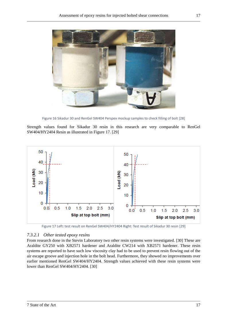
7.3.2 Alternative resin application for injection bolts In current research Sikadur 30 resin is investigated as a possible resin for use in injection bolts. From
Figure 16 results of test injections on Perspex mock-up samples with Sikadur 30 and RenGel SW404
can be seen. [28] The washers in the injection bolts have been optimized to ensure proper flow of resin
around the bolt shank. The different washer designs investigated in this research are shown in Figure
14. [28]
Figure 14 Bolt head washer designs investigated in research on Sikadur 30 and RenGel resin IBC in FRP structures [28]
In this research testing is performed on double lap shear specimens with FRP plate material. The
orientation of the bolts in the specimens is controlled to be concentric with the bolt hole clearance using
an installation jig which is shown in Figure 15 [28].
Figure 15 Installation jig to control bolt position in plate assembly [28]
Assessment of epoxy resins for injected bolted shear connections 17
7 State of the Art 17
Figure 16 Sikadur 30 and RenGel SW404 Perspex mockup samples to check filling of bolt [28]
Strength values found for Sikadur 30 resin in this research are very comparable to RenGel
SW404/HY2404 Resin as illustrated in Figure 17. [29]
Figure 17 Left: test result on RenGel SW404/HY2404 Right: Test result of Sikadur 30 resin [29]
7.3.2.1 Other tested epoxy resins
From research done in the Stevin Laboratory two other resin systems were investigated. [30] These are
Araldite GY250 with XB2571 hardener and Araldite CW214 with XB2571 hardener. These resin
systems are reported to have such low viscosity clay had to be used to prevent resin flowing out of the
air escape groove and injection hole in the bolt head. Furthermore, they showed no improvements over
earlier mentioned RenGel SW404/HY2404. Strength values achieved with these resin systems were
lower than RenGel SW404/HY2404. [30]

18 Assessment of epoxy resins for injected bolted shear connections
18 7 State of the Art
An update on research and application of Injection bolts is published as this research was ongoing. Here
Sikadur 33 and Sika AnchorFix are reported as injection resins for use in the repair of a roof structure
suffering reversal movements due to a suspended crane. [31] From this publication it is mentioned that
Sika AnchorFix was the most suitable resin for this application. The curing time was a lot shorter than
the Sikadur 33 resin which meant the crane had to be taken out of service for a shorter time period. [31]
It is also mentioned that the curing of Sika AnchorFix was more reliable. It is reported though that the
short duration resistance of the Sikadur 33 resin according to the specification of EN 1090 was 20%
higher than Sika AnchorFix [31] [8]. Also in this application reference is made to alternative washers
that facilitate the injection procedure instead of the hole in the bolt head as is specified in EN 1090 [8]
[31]
7.3.3 Other injection materials Parallel to this research carried out on epoxy resins for use in injection bolts the use of grout has been
investigated by M.P. Nijgh [32]. In this research similar strength values are reported for grout injected
connections as for resin injected connections. The successful injection though was dependent on the
washer positioning around the bolt head. [32] Furthermore, air inclusions were observed in the grout.
This is attributed to the use of super-plasticizer in the grout mixture. Results of short duration static tests
done on grout specimens in this research with different hole clearances is illustrated in Figure 18. [32]
Figure 18 Test results on grout injected bolted connections with different hole clearances [32]

Assessment of epoxy resins for injected bolted shear connections 19
7 State of the Art 19
7.4 Injection methods for resins Injection bolts can be injected successfully using hand-driven and air driven injection guns. Injection is
successful when the resin completely fills the void between the bolt shank and bolt hole [5]. The product
should also not run in between the plate surfaces during injection [5]. From research in the Stevin
Laboratory it was found that injection with hand-driven equipment does not pose any problems for short
bolt lengths. [33] For longer bolt lengths issues were seen in this research with hand-driven equipment.
Resin flowed out of the rear of the cylinder due to deformation caused by the high pressure applied. [33]
In this research air-driven injection equipment was also investigated for the injection. This proved to be
an effective method of filling the injection bolts also for long lengths. [33] Results of the injection time
required on M27 bolt specimens with a clamping length of 170 mm are reproduced here in Table 1. [33]
It is recommended to use high pressures when injecting long bolts in this research to limit the injection
time per bolt. [33]
Table 1 Injection times with various pressures for M27 injection bolts with 170 mm clamp length [33]
Applied pressure [Bar] Time to inject bolt [s]
7 80
7 284
13 25
10 130
13 29
7.4.1.1 Injection methods in other applications
Resin products are widely applied in the fabrication of composite structures in practice. In the fabrication
of composites two main methods are currently applied:
- Resin transfer moulding (RTM)
- Vacuum assisted transfer moulding (VARTM)
An illustration of these injection methods is shown in Figure 19. The main advantage of VARTM is the
removal of the top mould. This steel element is associated with high tooling costs and is replaced by a
vacuum bag in the VARTM process. Resin flow in these production methods is modelled in work by X.
Song [34]. The model developed by Song is used for optimizing flow velocity to reduce the porosity of
the resulting composite.

20 Assessment of epoxy resins for injected bolted shear connections
20 7 State of the Art
Figure 19 Illustration of RTM for composite fabrication [34]
Figure 20 Illustration of VARTM production process for composite structures [34]

Assessment of epoxy resins for injected bolted shear connections 21
7 State of the Art 21
7.5 Other considerations for Injection bolts
7.5.1.1 Curing time and temperature
The time necessary for curing to take place in an injection bolt is roughly 20 hours. This is sufficient for
regular construction methods because the connection is not immediately fully loaded. In specific
applications such as repairs on bridges which are in use this curing time cannot be reached before the
connection is loaded. [35]
In the Stevin Laboratory tests have been done on the effect of temperature on curing time in injection
bolts. [35] The conclusions of this research are that specimens which are heated after injection show
good resistance of around 182 𝑀𝑃𝑎 already 3 or 4 hours after curing. It is remarked though that heating
directly after injection causes the resin to flow out of the injection bolt. Therefore, it is recommended to
wait around 20 minutes after injection before the connection is heated. [35]
Relating this to the background on epoxies explained in Curing aspects of Epoxies the viscosity of the
resin decreases due to the applied increase in temperature. [14] [15] [18] The timeframe of 20 minutes
coincides with the pot life of RenGel SW404/HY2404 as supplied by the manufacturer. [24].
7.5.1.2 Presence of water during injection
Injection bolts are applied during fabrication of a steel structure on site. This means the structure is
exposed to weather influences. With this background research has been carried out in the Stevin
Laboratory to investigate the influence water presence has on the strength of injection bolts. [30] In this
research specimens were flushed with water immediately before injection. This had a significant
influence on the bearing strength of the connection. The results of this test series are shown in Figure
21. In this figure the specimens marked “w” were flushed with water immediately before injection. [30]
It is noted in this research that this is not a realistic situation for practical application. Therefore, a second
series of tests was performed, where specimens were assembled and left exposed to elements such that
water could penetrate the connection. The specimens were injected when one day of dry weather
occurred after a period of rain. [30] In this approach no differences in strength were observed between
dry and wet specimens. Therefore, it is recommended from this research to wait at least one day after
rain before injection of pre-assembled injection bolts takes place. [30]

22 Assessment of epoxy resins for injected bolted shear connections
22 7 State of the Art
Figure 21 load-slip results of 3 resin products in double lap shear tests in wet and dry application [30]
7.5.1.3 Combination of preload and injection
Research into the combination of a preloaded and injected connection has been done by various authors
[36] [37] [38] [39] [40]. In Figure 22 Results of Rugelj are shown [40]. In blue a connection with a
combination of preload and injection is shown, in black a connection with just preload and in green just
injection. The dots in corresponding colour as above show the characteristic value of these tests. [40]
The dot in red is the calculated capacity of a connection with injection and preload according to EN
1993-1-8. [41] This is lower than the tested value at a displacement of 0.15 mm. From this research it is
concluded that the calculated capacity according to EN 1993-1-8 is reached at a slip of 0.2 mm. [40]

Assessment of epoxy resins for injected bolted shear connections 23
7 State of the Art 23
Figure 22 load slip results of tests with injection, preloaded and injection-preloaded bolt connections [40]
It is noted though that the fatigue resistance of this combination is a point of discussion. Experimental
research has shown that the fatigue resistance of connections with preload and injection is lower than
preload alone [42]. Recent numerical analysis of connections with preload and fatigue though indicates
higher fatigue strength [39].
7.5.1.4 Demountability
At the end of the service life of a steel structure it can be disassembled to recycle the steel structure.
With this in mind, research has been done by Smits and Bouman on separating liquids in an injection
bolt application [43]. Recently the demountability of injected bolted connections has been researched
extensively by Nijgh [32]. From this research and earlier research an injection bolt can be disassembled
if a release agent is used. Without this precaution during assembly it is very difficult to disassemble the
bolt. [32]

24 Assessment of epoxy resins for injected bolted shear connections
24 7 State of the Art
7.5.2 Creep Resins show time-dependent behavior under loading. [44] The creep behavior of resins is dependent
upon the load placed on it as is evidenced by research. Further the temperature of the resin layer also
impacts the creep behavior [9] This is illustrated in Figure 23. As mentioned earlier the influence of
temperature for the applied resin in this test (RenGel SW404/HY2404) is moderate. [9] The average
creep at ambient temperatures was found to be 0.19 mm in this research while 0.24 mm was found at 70
degrees Celsius and a bearing stress of 250 𝑁𝑚𝑚2⁄ . [9]
The creep response of crosslinked polymers depends mostly on the crosslink density and the temperature
of the polymer [45]. A higher crosslink density will increase the dimensional stability of the product and
lower the creep rate [45]. A high crosslink density is associated with a high glass transition temperature
[20].
Figure 23 displacement over time of injection bolt at 70 degrees Celsius [9]
7.5.3 Durability of Injection Bolts The properties of epoxy resins are subject to degradation over time due to ageing processes. This can be
initiated through exposure to water, high temperatures and other aggressive fluids. [46] This is
documented in research into composites and adhesive joints. [46] [47] The combination of both water
presence and high temperatures on degradation processes is not yet well understood. [47] These
degradation processes could be of influence on the durability of an injection bolt if the connection is
exposed to them. An advantage of injection bolts is the corrosion protection. [5] In the ECCS
recommendations it is mentioned that internal corrosion of the steel structure is prevented by the resin
completely filling the cavity of the bolted connection. [5]

Assessment of epoxy resins for injected bolted shear connections 25
7 State of the Art 25
7.6 Regulations and standards
7.6.1 Injection bolts Regulations regarding the use of injection bolts in a structural engineering context are specified in EN-
1993-1-8 and EN-1090 [8] [41]. The regulations from standard EN1993-1-8 are related to the calculation
rules that can be used in the design and checking of injection bolts in structures. The regulation from
EN-1090 specifies the material and detailing of components for application as an injection bolt in a
structure.
7.6.2 Regulations regarding detailing and materials In Figure 24 a cross-section of an injection bolt fastener system is shown in a double lap shear
connection. The different components of the injection bolt assembly are shown in Figure 25. This
consists of the injection bolt, nut and the washers for the head and nut side.
7.6.3 Bolt The bolts that can be used as injection bolts are all fasteners of steel grade 8.8 and 10.9 that are allowed
for use in preloaded and non-preloaded connections. The details and regulations for fasteners are found
in EN 14399 and EN 15048 [48] [49]
For application as an injection bolt a hole must be made in the head of the bolt to facilitate the injection
of the resin material. The dimensions of this injection hole are specified in EN 1090 Annex K. This is
shown in Figure 26. [8]
Figure 24 Cross-sectional overview of an injection bolt fastener system [5]

26 Assessment of epoxy resins for injected bolted shear connections
26 7 State of the Art
Figure 25 Injection bolt assembly components
7.6.4 Washers To apply the injection of resin in the connection special washers must be used for the assembly. The
washer design that can be used for injection bolts is also outlined in annex K of EN-1090 [8]. This
washer design has a chamfered side on the head side to allow the resin to flow from the injection hole
around the bolt shank and into the hole clearance between the shank and the bolt holes in the plates. The
washer on the nut side has a groove machined into it. This allows air to escape from the cavity between
the bolt shank and bolt hole during injection to allow complete filling of the injection bolt. The
geometries of the chamfered side and machined air escape groove are shown in Figure 27. For an
example of these washers refer to Figure 25.
Figure 26 Specified dimensions of injection hole in bolt head from EN 1090 annex K [8]

Assessment of epoxy resins for injected bolted shear connections 27
7 State of the Art 27
Figure 27 left: chamfered washer on head side right: air escape groove washer on nut side [8]
7.6.5 Bolt holes in steel plates The bolt holes to be used for IBC are the same as regular bolted connections. The dimensions for these
holes are specified in the EN 1090 in section 6.6.1. The nominal dimensions of the bolt hole must be 2
mm larger than the bolt diameter for bolt sizes up to M27. For larger bolts the clearance is increased to
3 mm. These clearances are necessary to take tolerances during fabrication and erection into account for
assembly on-site. [8]
7.6.6 Resin The material used for injecting the bolt is specified in EN 1090. A two-component epoxy resin must be
used. The pot life of this product is required to be at least 15 minutes according to the guidelines. The
exact resin to be used is not specified in the codes. The result of the injection with the product is
specified. All cavities in the connection should be filled and resin should not flow out of the bolt after
the injection is stopped. [8]
7.6.7 Design and calculation of Injection bolts Design and calculation of injection bolts is guided by the calculation rules and methods explained in the
EN 1993-1-8 [41]. In the calculation of bolted connections, the connection class as outlined in Table 3.2
of EN 1993-1-8 determines the calculation method. Non-preloaded connections fall in Category A
connections. Category B and Category C connections are preloaded. Injection bolts are allowed to be
used for all three categories of connections. [41]
7.6.7.1 Static design resistance
The design shear load on an IBC should not exceed either the shear resistance of the bolt or the design
bearing resistance of the resin. For a preloaded injection bolt connection in category B or C the load
should not exceed the design slip resistance of the bolt plus the bearing resistance of the resin at the
relevant limit state. The design ultimate shear load should furthermore not exceed the design shear
resistance of the bolt and the bearing resistance of the bolt. [41]This is shown concisely below:
𝐹𝑅𝑑,𝐴 = min (𝐹𝑏,𝑅𝑑,𝑟𝑒𝑠𝑖𝑛, 𝐹𝑣,𝑅𝑑)
𝐹𝑅𝑑,𝐵/𝐶 = min (𝐹𝑠,𝑅𝑑 + 𝐹𝑏,𝑅𝑑,𝑟𝑒𝑠𝑖𝑛, 𝐹𝑣,𝑅𝑑 , 𝐹𝑏,𝑅𝑑)
The design bearing resistance that can be taken into account in an IBC is concisely defined in EN 1993-
1-8 as follows:
𝐹𝑏,𝑅𝑑,𝑟𝑒𝑠𝑖𝑛 =𝑘𝑡 ⋅ 𝑘𝑠 ⋅ 𝑡𝑏,𝑟𝑒𝑠𝑖𝑛 ⋅ 𝛽 ⋅ 𝑓𝑏,𝑟𝑒𝑠𝑖𝑛
𝛾𝑀4

28 Assessment of epoxy resins for injected bolted shear connections
28 7 State of the Art
Where:
𝐹𝑏,𝑅𝑑,𝑟𝑒𝑠𝑖𝑛 Is the bearing strength of an injection bolt
𝛽 Is a coefficient depending on the thickness ratio of the connected plates
𝑓𝑏,𝑟𝑒𝑠𝑖𝑛 Bearing strength of the resin
𝑡𝑏,𝑟𝑒𝑠𝑖𝑛 Effective bearing thickness of the resin
𝑘𝑡 Coefficient for the limit state (1.0 for SLS and 1.2 for ULS)
𝑘𝑠 Coefficient for the hole clearance (1.0 − 0.1 ⋅ 𝑚)
𝑚 The difference in mm between the normal and oversized diameter to be used for
𝑘𝑠
The coefficient 𝑘𝑡 considers the difference in the short term allowable bearing stress compared to the
long term bearing stress of the resin, where creep of the resin layer plays an important role. The value
1.2 is chosen by engineering judgement. [31]
The values to be used for coefficients 𝛽 and 𝑡𝑏,𝑟𝑒𝑠𝑖𝑛 are shown in Table 2. These coefficients consider
the connection geometry. The stress occurring in the resin layer depends on the ratio of the thicknesses
of the cover and center plate in the connection as exemplified in Figure 28.
Figure 28 Resin layer stress in IBC depending on the ratio of plate thicknesses [41]
Table 2 coefficients β and tb,resin depending on t1/t2 for use in calculation of design bearing resistance [41]
The coefficient 𝑡𝑏,𝑟𝑒𝑠𝑖𝑛 considers the total thickness of the plate package. The stress distribution in the
resin layer does not remain uniform for larger values of the L/D ratio. This is caused by bending
deformation of the bolt. Only an effective length of the resin layer can be taken into account for the
calculation for long joints. This is illustrated in Figure 29.

Assessment of epoxy resins for injected bolted shear connections 29
7 State of the Art 29
Figure 29 actual and effective resin stress distribution take into account in long joints with IBC [5]
7.6.8 Resin test procedure for injection bolts The procedure for testing the allowable bearing stress on the resin product in IBC is outlined in annex
G of EN 1090 [8]. This procedure outlines the test of slip factor determination of preloaded connections
but should also be used for injection bolts. The resin must be tested in double lap shear connections with
specimen geometry according to Figure 31. The specimen on the left must be used with M20 bolts and
∅22 mm holes. The specimen on the right must be applied with M16 bolts in ∅18 mm holes. [8]
For injection bolts the specimen must be assembled such that the resin layer loaded in compression is
maximized. [8] This is the most unfavorable loading position since the resistance is determined at a set
displacement. With a thicker resin layer the strain in the resin is lower to reach the displacement and a
lower strength value results. An illustration of the resulting bolt position and resin layer is shown below:
Figure 30 Resin layer in most unfavorable position of bolt for test procedure of EN 1090
Furthermore, the surface treatment of specimens must be the same as will be applied in the application
for which testing takes place. Also Resin curing time must be explained. Either by referring to
recommendations or through a description of the real procedure. [8]

30 Assessment of epoxy resins for injected bolted shear connections
30 7 State of the Art
Test procedure outlines initially 5 specimens must be tested. 4 test specimens must be tested in the
regular way which is a load controlled tensile test, with a loading speed such that total test time ranges
between 10 and 15 minutes. The slip in the connection should be measured through the relative slip
between the center and cover plates of the specimen in the heart of the connection. This is indicated in
Figure 31 as points a and b. The test is considered finished when an average slip at these points a and b
on both sides of the connection of 0.15 mm is measured. Each connection gives a separate slip force at
0.15 mm. [8]
The fifth specimen in the test protocol should be loaded to 90% of the average slip force of the previous
4 specimens (so 8 results). For this fifth specimen, the slip in the connection 5 minutes after this 90%
value is reached should be recorded. If the change in displacement 3 hours after applying the load is
less than 0.002 mm the specimen should be loaded as the previous four specimens. [8]
If the 0.002 mm value is crossed an extended creep test should be done on the connection to verify long
term bearing stress. [8]
Figure 31 Prescribed specimen geometry for testing of allowable resin bearing stress in injection bolts [8]
The extended creep procedure specifies 3 specimens (6 connections) should be tested. The load should
be chosen using the result from the short duration creep test on the fifth specimen as mentioned above
and any already performed extended creep tests. Secondly the force for this creep test can also be
selected based on the specific application for which testing is carried out. [8]
In the long duration creep test it must be verified that the slip in the connection for the service life of the
structure, 50 years unless otherwise specified, shall not exceed 0.3 mm. For the assessment of results a
displacement- time diagram shall be plotted with time on a log scale. In this graph the displacement may
be extrapolated linearly to determine that the specimen meets the 0.3 mm slip requirement at the service
life time. This is shown in Figure G.2 of EN1090. Reproduced here below in Figure 32. Here three
results are shown with the linear extrapolation of the curves of specimen 1 and 2 shown in a dashed line
[8].

Assessment of epoxy resins for injected bolted shear connections 31
7 State of the Art 31
Figure 32 load-log time diagram of extended creep test procedure from annex G EN 1090 [8]
7.6.9 Other relevant regulations for injection bolts To set the stage regarding the state of regulation and research into other load cases than mentioned above
in Design and calculation of Injection bolts are discussed here. These load types are not applied in this
research but it gives an idea of the state of the art regarding injection bolts in a broader application.
7.6.10 Fatigue loading for Injection bolts The structural resistance of connections loaded by fatigue loads is governed by the standard EN 1993-
1-9 [50]. The main determinant of fatigue loading is the detail category of a connection. [50] This
number represents the constant amplitude stress range for which the design value of the resistance in
number of cycles is 2 ⋅ 106 for that type of connection. The detail category for fatigue loading of IBC
in double lap shear joints is shown in Table 3 below against those for normal bolted connections.
Table 3 Fatigue detail category of double lap shear joints with regular- and injection bolts
NON-
PRELOADED
PRELOADED
REGULAR BOLTED
CONNECTION 50 112
INJECTION BOLT
CONNECTION 90 112
7.6.11 Pre-tensioned connections As discussed previously shear connections with bolts can be either preloaded or non-preloaded. In
category B/C connections preload takes care of (part) of the load transfer. This is done through friction
between the contact surfaces of the connected steel plates. This is illustrated in Figure 33.
The design resistance of this type of connection is discussed in EN 1993-1-8. Important for load transfer
is the contact surface between the plates. This is taken into account in the slip factor 𝜇 which depends
on the surface treatment of the steel plates in the connection. [41]

32 Assessment of epoxy resins for injected bolted shear connections
32 7 State of the Art
Figure 33 Load transfer of shear connection through bearing (left) and friction due to pretension (right) [51]

Assessment of epoxy resins for injected bolted shear connections 33
8 Material and Methods 33
8 Material and Methods In this chapter the procedure for performing of tests and the used materials are explained to answer the
research goals of this Master thesis. First the selected alternative resins will be discussed.
8.1 Resin Selection From the review of the state of the art reported on in Chapter 7 it was found that limited knowledge is
available about possible alternative resins for the injection bolt application. From a review of the
chemical properties and background on epoxy resins the following properties were identified as
important parameters for this application:
• The viscosity of the resin mixture
• The pot life of the resin product
• The glass transition temperature of the resin product after curing
• The curing shrinkage of the resin product
• Mechanical properties of the resin after curing.
Also, successful application of a resin product in IBC in other research is considered for the selection of
alternative resins. (Note: at the time of resin selection the author of this research was unaware of the use
of Sika AnchorFix and Sika Sikadur 33 for injection bolts as reported on by Gresnigt [31])
Due to the limited knowledge about the optimal range of the aforementioned parameters for this
application suppliers of resin products were contacted directly to discuss the possibilities. From this
contact with manufacturers and by considering the done research on resins for injection bolts products
were selected for testing.
An overview of the used products for this experimental program and some general remarks about their
basic properties is given here. For the resin products used in this research detailed information from the
PDS is attached in Appendix 16.
8.1.1 RenGel SW404/HY2404 The currently applied epoxy resin in practice RenGel SW404 with HY2404 is used as a reference for all
tests. This resin is the benchmark against which the alternatives can be measured. This product has a
bright blue color after mixing. For detailed product specifications refer to the attached PDS in Appendix
16. [36] In Figure 35 the two resin components are shown. In Figure 34 a Perspex mockup sample of
an injection bolt with RenGel Resin is shown.

34 Assessment of epoxy resins for injected bolted shear connections
34 8 Material and Methods
Figure 34 Perspex mockup sample with RenGel SW404/HY2404 resin
Figure 35 RenGel SW404 resin with HY2404 hardener
8.1.2 Sika Sikadur-30 Resin Sikadur-30 is one of the alternative resins tested in IBC’s in this research. This product has a grey color
after mixing. In Figure 36 the resin applied in an IBC is shown. For detailed product specifications refer
to the attached PDS in Appendix 16. [52]

Assessment of epoxy resins for injected bolted shear connections 35
8 Material and Methods 35
Figure 36 Sikadur-30 resin in demounted IBC
8.1.3 Sika Injection 451 Resin Sika Injection 451 is another alternative resin used in the testing procedure. This resin product is
transparent with a slight yellow hue to it after mixing. The viscosity is far lower than the other products
appearing almost water-like after mixing. The viscosity mentioned in the PDS of this resin is 100 𝑚𝑃𝑎 ⋅
𝑠. [53] For more detailed product information refer to Appendix 16 where the PDS is attached [53]. In
Figure 37 the two components of the resin packaging are shown.
Figure 37 Sika Injection 451 components
8.1.4 Edilon Dex R2K resin Edilon Dex R2K resin is a product used for structural bonding of anchors in concrete structures. [54]
This resin has a very dark grey color after mixing. This product is supplied in a double caulk tube with
the correct resin component ratio. This resin is mixed with a special nozzle that fits on this double caulk
tube packaging. A special injection gun is used for this double cylinder caulk tube. For detailed product
specifications refer to the PDS of this resin attached in Appendix 16. [54] The mixing nozzle, injection
gun and resin packaging is shown in Figure 38 and Figure 39.

36 Assessment of epoxy resins for injected bolted shear connections
36 8 Material and Methods
Figure 38 Edilon Dex R2K injection gun
Figure 39 Dex R2K double caulk tube packaging and mixing nozzle
8.1.5 Edilon Dex G 20 Resin Edilon Dex G 20 is the second product from manufacturer Edilon)(Sedra tested as a possible alternative
for RenGel SW404/HY2404. This resin is normally applied through pouring [55]. Contrary to Edilon
Dex R2K this resin is mixed manually and supplied as two separate components. The viscosity of this
resin is 11 𝑃𝑎 ⋅ 𝑠 at 25 degrees as stated in the PDS of the product. [55] Refer to the full details of this
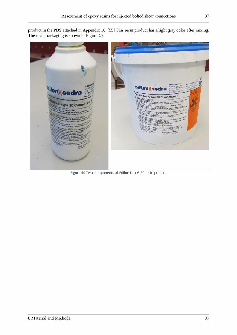
Assessment of epoxy resins for injected bolted shear connections 37
8 Material and Methods 37
product in the PDS attached in Appendix 16. [55] This resin product has a light gray color after mixing.
The resin packaging is shown in Figure 40.
Figure 40 Two components of Edilon Dex G 20 resin product

38 Assessment of epoxy resins for injected bolted shear connections
38 8 Material and Methods
8.2 Other used material To perform testing in the Stevin laboratory on injection bolts several materials were used. These are
discussed below.
8.2.1 Fasteners The bolts used for this experimental program are HV 10.9 bolts modified for use as injection bolts. A
hole is drilled in the head according to the dimensions specified in EN 1090-2. These hole dimensions
are shown in Figure 41.
Figure 41 hole in bolt head for IBC [8]
The washers used are also according to EN 1090-2 for use in IBC applications. The washer at the bolt
head side has a chamfered side which allows resin to flow from the hole in the bolt head around the
shank of the bolt and into the bolt hole. The washer at the nut side has a machined groove to let air
escape from the connection during injection.
Figure 42 chamfered washer and air escape groove washer overview [8]
The nuts are standard HV 10.9 nuts with oversized thread to work in conjunction with the galvanized
thread of the bolts. A full fastener assembly is shown in Figure 43.

Assessment of epoxy resins for injected bolted shear connections 39
8 Material and Methods 39
Figure 43 Fastener assembly of injection bolt with bolt, washers and nut
8.2.2 Plate Material All plate material used in the experimental program is steel. The steel grade used was S355. The plates
in the testing program were reused from preload slip factor tests performed in the Stevin laboratory. The
dimensions of specimens were conform the guidelines laid out in NEN-EN 1090-2. [8] An overview of
the used plate dimensions is shown in Figure 44.
Figure 44 Plate dimensions double lap shear test specimen
For the tests on the resin stress distribution with long bolt lengths leftover plate material from the lab
was re-used. This was cut to size to be used as a test specimen. An overview of the steel plate dimensions
used in the long bolt tests is shown in Figure 45 and Figure 46.

40 Assessment of epoxy resins for injected bolted shear connections
40 8 Material and Methods
Figure 45 Plate dimensions for long bolt test l/d ratio 3
Figure 46 Plate dimensions for long bolt test l/d ratio 4
The plate material used in testing had varying surface treatments. This meant the slip factor 𝜇 varied
between specimens. A qualitative overview of the different faying surfaces is given in the following
table:
Surface treatment Indication of slip factor [56]
Grit blasted 0.5
Zinc spray-metallized 0.4
Epoxy coating Very low

Assessment of epoxy resins for injected bolted shear connections 41
8 Material and Methods 41
8.3 Tools For the assembly of specimens some general and specific tools were used. These are discussed in order.
8.3.1 Injection gun For the injection, a hand operated injection gun is used. This allows the operator to get a better feel of
the resin flow during the injection through the applied pressure. The used resin products are two
component epoxy resins. They are mixed according to the manufacturer specifications as supplied in the
PDS of the respective product, using a scale. The resin is then poured into a caulk tube which can be
used in the injection gun. An injection nozzle is screwed onto this caulk tube that fits in the hole in the
bolt head. The tube is sealed at the back using a plastic end cap. images of the caulk tube, plastic caps
and injection nozzles as well as the used injection gun are shown in the figures below:
Figure 47 Hand-Driven injection gun used to inject bolts

42 Assessment of epoxy resins for injected bolted shear connections
42 8 Material and Methods
Figure 48 Caulk tube with injection nozzle and tube end cap
For the Dex R2K resin a different injection gun was supplied. This injection is also hand driven. The
Dex R2K caulk tube is placed directly in this injection gun and a mixing nozzle is attached to the tube.
To correctly inject the bolt a standard injection nozzle is cut to size to fit on the mixing nozzle of the
Dex R2K product, since this had a too large opening to fit inside the hole in the head of the bolt. The
mixing nozzle is already shown in Figure 39.
8.3.2 Other general tools To assemble the fastener systems for the IBC specimens some other general tools were used. These
include various wrenches as well as a torque wrench to apply a specific preload in the nuts during the
injection and curing of specimens. Furthermore, modelling clay was used to close the air escape groove
and hole in the bolt head for resins which flowed out of these openings after finishing the injection
procedure. The used clay for closing the openings of the IBC is shown in Figure 49.

Assessment of epoxy resins for injected bolted shear connections 43
8 Material and Methods 43
Figure 49 Modelling clay used for closing air escape groove and bolt head hole

44 Assessment of epoxy resins for injected bolted shear connections
44 8 Material and Methods

Assessment of epoxy resins for injected bolted shear connections 45
9 Test procedure and setup 45
9 Test procedure and setup
The tests performed in this research are double lap shear tests on IBCs. Two test setups in the Stevin II
laboratory of the TU Delft are used to perform the tests. In both machines the specimen is placed
vertically and fixated with hydraulic clamps at the top and bottom of the center plate of the specimen.
The load on the specimen is applied by a hydraulic jack located in the bottom of the machine. The
maximum load of machine 1 is 500 kN (hydraulic clamp capacity), used for all tests on standard
specimen dimensions. The other machine used for double lap shear tests on specimens with thicker
plates has a maximum load of 600 kN. An overview of specimens in the testing rigs is shown in Figure
50.
Figure 50 Test specimens in test rigs for double lap shear tests

46 Assessment of epoxy resins for injected bolted shear connections
46 9 Test procedure and setup
9.1 Specimen assembly and fabrication Specimens used for testing in this research are assembled in the Stevin Laboratory of the TU Delft. The
method used for assembling the specimens to ensure proper test results is discussed now in detail.
To assemble a specimen the center- and cover plates are placed on a flat working surface in the lab and
the bolt holes drilled in the plates are aligned for assembly. The bolts to be used in the specimen are
checked visually to see no debris is inside the injection hole in the bolt head. If this was the case any
metal shrapnel from drilling was removed before continuing assembly.
The bolt, nut and washer assembly is then placed in the bolt holes of the steel plate and tightened loosely
by hand. After this step, the washers are checked to verify that the washers of the bolt head side and nut
side are placed in the right place and with the flat side of the washer facing the steel plates.
Following the guidelines for testing of annex G EN-1090 the center plates of the double lap shear
connection are pushed together manually to create the most unfavorable position of the bolt in the bolt
hole. [8] This procedure guarantees the maximal resin layer thickness is placed in the compressed side.
The resulting bolt shank positioning inside the bolt hole and resulting resin layer is illustrated in Figure
51.
Figure 51 unfavorable bolt shank position in bolt hole for IBC testing
After the plates are pushed together the assembly of the fastener system is checked for correct orientation
of the components. The injection hole in the bolt head should be placed at the top. The air escape groove
of the washer on the nut side is also placed facing upwards.
The nuts are tightened using a torque wrench to prescribed torque. This is done to prevent the steel plates
of the specimen to move during handling. It also prevents the resin penetrating from the bolt hole into
the contact surfaces of the steel plates in the connection. The used assembly torque is varied throughout
this research. These will be discussed in the test overview of Section 9.6.

Assessment of epoxy resins for injected bolted shear connections 47
9 Test procedure and setup 47
After specimen assembly was completed the specimens were either placed in a refrigerator at a set
temperature or injected directly. Specimens for which temperature is controlled were left in the
refrigerator for at least 24 hours before injection to ensure they reached the desired temperature. The
refrigerator used for this is shown in Figure 52. The refrigerator is temperature controlled and is double-
checked using a thermometer attached to a laptop to verify the correct temperature.
Figure 52 Refrigerator used for controlling curing temperature of specimens
9.2 Specimen injection Following the assembly and cooling of specimens the specimen is injected with resin for testing. For the
injection procedure, the specimen is again placed on a flat working surface with the bolts horizontal.
The hole in the bolt head for injection is again placed on the top side of the connection to prevent air
inclusions.
For the injection, the two resin components are mixed in the ratio as supplied in the manufacturer
specifications. The quantity of resin mixed for injection is enough to fill all the bolts of a specimen. The
preparation of resin is done by weighing the two components of the resin in small mixing cups using a
scale. These are then mixed by hand until a homogeneous resin mixture is created.
For the injection a caulk tube is prepared by cutting off the top and screwing an injection nozzle onto it.
The resin mixture is poured into the caulk tube taking care to keep the tip of the injection nozzle closed.
After pouring the resin into the tube it is tapped on the working surface to compact the resin and remove
air in the tube as much as possible. Then a plastic end cap is inserted in the top of the caulk tube to seal
the tube at the rear.
The caulk tube assembly is placed in the hand-driven injection gun. The piston of the injection gun is
pushed until all air in the tip of the injection nozzle is gone and some resin flows out of the tip of the
nozzle. The resin is then injected through the hole in the bolt head until the operator sees resin flowing
out of the air escape groove washer on the nut side of the specimen. During injection the pressure applied
using the injection gun is high, care must be taken to not apply too much pressure as deforming the
plastic end cap results in resin flowing out of the rear of the caulk tube.

48 Assessment of epoxy resins for injected bolted shear connections
48 9 Test procedure and setup
9.2.1 Dex R2K injection For the Edilon Dex R2K resin the injection procedure was changed slightly. This product is supplied as
a complete system. For this resin a specific hand-driven injection gun is used with a supplied mixing
nozzle, that mixes the two resin components during injection. To use this product in the IBC application
a standard injection nozzle is cut to size to fit on the mixing nozzle supplied with the resin. This to ensure
a proper seal of the hole in the bolt head and enable injection of the bolt.
For the mixing procedure of this resin the manufacturer application guidelines are followed [57]. When
starting with application the first amount of resin from the mixing nozzle is discarded until the resin
mixture is a homogeneous dark grey in color. Injection is only started after this initial unmixed resin is
discarded from the nozzle. [57]
9.3 Specimen preparation for testing Before testing is started a last step in preparing the specimen is done. The brackets to mount the LVDTs
used for measurements during testing are attached to the specimen. This is done by clamping the bracket
with screws on the plates of the specimen and by screwing the mounting bracket onto specially tapped
holes in the side of the steel plate specimens. When the specimen is placed in the testing rig the nuts of
the fasteners are loosened and then retightened loosely hand-tight. This is done to remove the preload
that was introduced during the assembly and curing of the specimens.

Assessment of epoxy resins for injected bolted shear connections 49
9 Test procedure and setup 49
9.4 Test procedure and measurement setup The measurement setup for the double lap shear tests is taken from the guidelines of annex G of EN
1090 [8]. The load-slip curve of the specimen must be recorded during testing. The slip in the connection
is measured in the CBG at both sides of the connection to account for any rotation of the plates during
testing. Additional measuring of the slip on the PE of the cover plate is done in this research. In total 12
LVDTs are used to measure the displacements. The LVDTs used are high precision with a measurement
range of 2 mm and an accuracy of 1 micron. This measurement setup is reused from earlier testing on
double lap shear connections using friction grip connections [56]. An illustration of the mounting
brackets and LVDT setup from the earlier testing program is shown in Figure 53.
Figure 53 LVDT measurement bracket setup [56]
Testing performed on specimens for bolt length influence was done in a different tensile machine. For
these specimens the measurement setup consisted of 4 LVDTs measuring the slip of the connection only
at the plate edges of both connections. An image of the LVDTs mounted to the specimen is shown in
Figure 54. The distance of the LVDT mounting bracket to the plate edge is controlled during assembly
to be 35 mm using a steel spacer block when tightening the LVDT bracket to the plate.

50 Assessment of epoxy resins for injected bolted shear connections
50 9 Test procedure and setup
Figure 54 LVDTs measuring slip at PE of LD4 specimen
The load placed on the specimen is measured by the tensile test rig itself. Combining the measurements
from the LVDTs and the force from the tensile test setup results in two separate load-slip curves for the
top and bottom connection of every specimen.
9.5 Loading procedure As stated before the guidelines from annex G of EN-1090 are followed. The specimen is loaded in
tension with a force controlled protocol. The test is considered finished when a relative slip between
inner- and outer plates of 0.15 mm in both connections of the specimen occurs. Which is the average of
the displacement at both sides of the connection measured in the CBG.
In this research three distinct load procedures are used to test the specimens. All procedures start from
the guidelines of EN-1090. The total time of the test procedure to reach the 0.15 mm slip value should
be between 10 and 15 minutes. [8]
The initial load procedure is shown in Figure 55. The load rate for this test to reach the 0.15 mm slip
value is at 0.3 𝑘𝑁𝑠⁄ . After the test result according to the guideline of EN-1090 is found, the load is
removed and a small compressive force is introduced before loading the specimen again to 90% of the
load that was found at the 0.15 mm slip value. This load is then kept constant for a minimum of 6 hours
before the specimen is unloaded and removed from the test setup. This provides information on the time-
dependent behavior of the resin under high loads.

Assessment of epoxy resins for injected bolted shear connections 51
9 Test procedure and setup 51
Figure 55 Initial load procedure for double lap shear tests
The second load procedure that was used in this research is shown in Figure 56. Again, the test is started
according to the EN-1090 guidelines. The load rate of this test procedure is 0.2 𝑘𝑁𝑠⁄ to conform to the
loading time specified in EN-1090. After the 0.15 mm slip at the CBG is reached the load rate is
increased to 1.0 𝑘𝑁𝑠⁄ . The load is increased until the maximum load of the test setup, 500 kN, is
reached. This provides information on the resin behavior when it is overloaded according to EN-1090.
Figure 56 second load procedure with 0.15 mm slip protocol and overload
The final load procedure that is used in this research program is the exact protocol of EN-1090
guidelines. This is shown in Figure 57. Here the load rate is again 0.2 𝑘𝑁𝑠⁄ but no additional testing is
done after the 0.15 mm slip value is reached. The specimen is simply unloaded and removed from the
test setup.

52 Assessment of epoxy resins for injected bolted shear connections
52 9 Test procedure and setup
Figure 57 Third load procedure for double lap shear tests
9.6 Overview of performed tests and investigated parameters Testing in this research has taken place in several test series. Each test series has a different focus and
number of specimens tested. An overview of the number of tested specimens for each series of tests is
shown in Table 4. Due to the large variation in parameters throughout this testing program a coding
system to identify specimens is set up that indicates the values of the varied parameters. The used code
shorthand is set out in Table 5. Each of the test series and the parameters varied in the series is discussed
in more detail in the following sections. The aim of each series and how it relates to the research goals
laid out in the introduction and problem definition is shown graphically in Figure 58.
Table 4 Number of tests performed in each test series
Test series Test series identifier
number of specimens
Aim of the series
initial feasibility tests In 5 Feasibility of application
temperature dependency tests T1 12 Mechanical performance of resin products
temperature dependency retests
T2 6 Mechanical performance of resin products
temperature dependency retests 2
T3 4 Mechanical performance of resin products
spread of Dex R2K DS 4 Mechanical performance of resin products
Bolt length influence 1 BL1 4 Stress distribution of resin layer
Bolt length influence 2 BL2 4 Stress distribution of resin layer

Assessment of epoxy resins for injected bolted shear connections 53
9 Test procedure and setup 53
Table 5 Coding system for specimens
Test series
Resin types specimen dimensions
temperature plate surface
assembly torque
load procedure
Specimen number*
In RenG LD2 8 Zn hand init 1
T1 dG20 LD3 16 Ep 100 Nm slipmax 2
T2 dR2K LD4 24 Gb 30 Nm slip 3
T3 Sd30
amb
60 Nm
4
DS Inj451
BL1
BL2
*for specimens with the same parameters an alphanumerical number is added to identify each specimen uniquely
Assessment of Epoxy resins for IBC
Initial tests T1
T2
T3
DS BL1
BL2
Feasibility of application
Mechanical performance of resins
Modelling stress distribution in resin
Figure 58 Aim of test series in research project
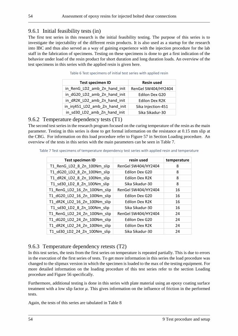
54 Assessment of epoxy resins for injected bolted shear connections
54 9 Test procedure and setup
9.6.1 Initial feasibility tests (in) The first test series in this research is the initial feasibility testing. The purpose of this series is to
investigate the injectability of the different resin products. It is also used as a startup for the research
into IBC and thus also served as a way of gaining experience with the injection procedure for the lab
staff in the fabrication of specimens. Testing on these specimens is done to get a first indication of the
behavior under load of the resin product for short duration and long duration loads. An overview of the
test specimens in this series with the applied resin is given here.
Table 6 Test specimens of initial test series with applied resin
Test specimen ID Resin used
in_RenG_LD2_amb_Zn_hand_init RenGel SW404/HY2404
in_dG20_LD2_amb_Zn_hand_init Edilon Dex G20
in_dR2K_LD2_amb_Zn_hand_init Edilon Dex R2K
in_inj451_LD2_amb_Zn_hand_init Sika Injection-451
in_sd30_LD2_amb_Zn_hand_init Sika Sikadur-30
9.6.2 Temperature dependency tests (T1) The second test series in the research program focused on the curing temperature of the resin as the main
parameter. Testing in this series is done to get formal information on the resistance at 0.15 mm slip at
the CBG. For information on this load procedure refer to Figure 57 in Section Loading procedure. An
overview of the tests in this series with the main parameters can be seen in Table 7.
Table 7 Test specimens of temperature dependency test series with applied resin and temperature
Test specimen ID resin used temperature
T1_RenG_LD2_8_Zn_100Nm_slip RenGel SW404/HY2404 8
T1_dG20_LD2_8_Zn_100Nm_slip Edilon Dex G20 8
T1_dR2K_LD2_8_Zn_100Nm_slip Edilon Dex R2K 8
T1_sd30_LD2_8_Zn_100Nm_slip Sika Sikadur-30 8
T1_RenG_LD2_16_Zn_100Nm_slip RenGel SW404/HY2404 16
T1_dG20_LD2_16_Zn_100Nm_slip Edilon Dex G20 16
T1_dR2K_LD2_16_Zn_100Nm_slip Edilon Dex R2K 16
T1_sd30_LD2_8_Zn_100Nm_slip Sika Sikadur-30 16
T1_RenG_LD2_24_Zn_100Nm_slip RenGel SW404/HY2404 24
T1_dG20_LD2_24_Zn_100Nm_slip Edilon Dex G20 24
T1_dR2K_LD2_24_Zn_100Nm_slip Edilon Dex R2K 24
T1_sd30_LD2_24_Zn_100Nm_slip Sika Sikadur-30 24
9.6.3 Temperature dependency retests (T2) In this test series, the tests from the first series on temperature is repeated partially. This is due to errors
in the execution of the first series of tests. To get more information in this series the load procedure was
changed to the slipmax version in which the specimen is loaded to the max of the testing equipment. For
more detailed information on the loading procedure of this test series refer to the section Loading
procedure and Figure 56 specifically.
Furthermore, additional testing is done in this series with plate material using an epoxy coating surface
treatment with a low slip factor 𝜇. This gives information on the influence of friction in the performed
tests.
Again, the tests of this series are tabulated in Table 8

Assessment of epoxy resins for injected bolted shear connections 55
9 Test procedure and setup 55
Table 8 Temperature dependency retests with the surface treatment, temperature and resin per specimen
Test specimen ID resin used temperature faying surface
T2_RenG_LD2_8_Zn_100Nm_slipmax RenGel SW404/HY2404 8 Zinc
T2_RenG_LD2_8_Ep_100Nm_slipmax RenGel SW404/HY2404 8 Epoxy coat
T2_dR2K_LD2_8_Zn_100Nm_slipmax Edilon Dex R2K 8 Zinc
T2_dR2K_LD2_8_Ep_100Nm_slipmax Edilon Dex R2K 8 Epoxy coat
T2_RenG_LD2_16_Zn_100Nm_slipmax RenGel SW404/HY2404 16 Zinc
T2_dR2K_LD2_16_Zn_100Nm_slipmax Edilon Dex R2K 16 Zinc
9.6.4 Spread of Dex R2K test series (DS) The purpose of this test series is to investigate the spread that occurs in results with Dex R2K specimens
with a larger set of results. For these specimens, the torque applied during the specimen assembly
procedure was changed to 30 𝑁𝑚. This is varied to remove any influence of friction between the plate
surfaces on the results. The tested specimens in this series are shown in Table 9.
Table 9 Test specimens used to investigate spread and temperature behavior of Edilon Dex R2K
Test specimen ID resin used temperature assembly
torque
DS_dR2K_LD2_16_Zn_30Nm_slipmax_1 Edilon Dex R2K 16 30 Nm
DS_dR2K_LD2_16_Zn_30Nm_slipmax_2 Edilon Dex R2K 16 30 Nm
DS_dR2K_LD2_16_Zn_30Nm_slipmax_3 Edilon Dex R2K 16 30 Nm
DS_dR2K_LD2_16_Zn_30Nm_slipmax_4 Edilon Dex R2K 16 30 Nm
9.6.5 Temperature dependency retests 2 (T3) In this test series testing was only performed on Edilon Dex R2K resin. The purpose here is to complete
the investigation into curing temperature dependency with the adapted procedure to eliminate friction
from the results. The load procedure used is again the slipmax variant as illustrated in Figure 56. The
specimens tested are shown in Table 10.
Table 10 Test specimens for temperature dependency retests 2
Test specimen ID resin used temperature assembly
torque
T3_dR2K_LD2_8_Zn_30Nm_slipmax_1 Edilon Dex R2K 8 30 Nm
T3_dR2K_LD2_8_Zn_30Nm_slipmax_2 Edilon Dex R2K 8 30 Nm
T3_dR2K_LD2_24_Zn_30Nm_slipmax_1 Edilon Dex R2K 24 30 Nm
T3_dR2K_LD2_24_Zn_30Nm_slipmax_2 Edilon Dex R2K 24 30 Nm
9.6.6 Bolt length influence 1 This test series investigates the behavior of IBC with a thicker plate package in relation to the bolt
diameter. Two different values for the 𝑙
𝑑 ratio are tested in this series. Due to the different specimen
dimensions used in this series, a different tensile testing machine was used to perform tests. The resin
product used in this series is RenGel SW404/HY2404. The specimen curing in this series is done in the
ambient temperature of the lab. The plates used for these specimens are fabricated from leftover steel

56 Assessment of epoxy resins for injected bolted shear connections
56 9 Test procedure and setup
plates from the Stevin II laboratory of the TU Delft. The surface treatment of this plates is grit-blasted.
An overview of the performed tests can be found in Table 11.
Table 11 Tests performed for the Bolt Length influence test series 1
Test specimen ID resin used l/d ratio
specimen temperature
assembly torque
BL1_RenG_LD3_amb_Gb_30Nm_slip_1 RenGel SW404/HY2404 3 ambient 30 Nm
BL1_RenG_LD3_amb_Gb_30Nm_slip_2 RenGel SW404/HY2404 3 ambient 30 Nm
BL1_RenG_LD4_amb_Gb_30Nm_slip_1 RenGel SW404/HY2404 4 ambient 30 Nm
BL1_RenG_LD4_amb_Gb_30Nm_slip_2 RenGel SW404/HY2404 4 ambient 30 Nm
9.6.7 Bolt length influence 2 This series is performed to gain more confidence in the test results from the first series on Bolt length
influence. These tests are performed by sand blasting the specimens from the first series on bolt length
influence until they are clean and the plates are reused for these tests. The only parameter that was
changed between this series and the previous one on bolt length influence, is the applied torque during
specimen assembly, this was raised to 60 𝑁𝑚. A final test specimen overview can be found in Table 12.
Table 12 Overview of second series on the influence of bolt length on resin stress distribution
Test specimen ID resin used l/d ratio specimen
temperature assembly torque
BL2_RenG_LD3_amb_Gb_30Nm_slip_1 RenGel SW404/HY2404 3 ambient 60 Nm
BL2_RenG_LD3_amb_Gb_30Nm_slip_2 RenGel SW404/HY2404 3 ambient 60 Nm
BL2_RenG_LD4_amb_Gb_30Nm_slip_1 RenGel SW404/HY2404 4 ambient 60 Nm
BL2_RenG_LD4_amb_Gb_30Nm_slip_2 RenGel SW404/HY2404 4 ambient 60 Nm
9.7 Curing time research All specimens tested in this research have had a curing time of at least 24 hours at the specified
temperature. The test program carried out in the Stevin laboratory of the TU Delft was more extensive
than just the tests of this research. Experiments relating to the curing time of resin products in IBC was
carried out in the laboratory as well [58]. Due to the large relevance of these tests for this research topic
the results of this series are also discussed in the results section shortly.
The approach to testing and assembling of specimens of the series of tests performed by J. Li is the same
as reported above for this research [58]. Two different load procedures were used in this research into
the effect of curing time. These are reproduced here in Figure 59 and Figure 60.
Figure 59 Short3-1 load procedure from curing time research

Assessment of epoxy resins for injected bolted shear connections 57
9 Test procedure and setup 57
Figure 60 Short3-2 load procedure from curing time research

58 Assessment of epoxy resins for injected bolted shear connections
58 9 Test procedure and setup

Assessment of epoxy resins for injected bolted shear connections 59
10 Results 59
10 Results
10.1 Initial feasibility of alternative resins To verify the feasibility of the resin products mentioned in section 8.1, one specimen was tested for each
product, according to the procedure mentioned in section 9. After testing of these specimens, they were
disassembled for a visual inspection. This will be discussed first, then the results of the connection tests
will be discussed.
10.1.1 Visual inspection
10.1.1.1 Voids in injection bolt specimens
Research is done on injection bolt specimens in relation to voids in the resin layer. For this an injection
bolt is cut from a steel specimen and placed inside a CT scan. This allows us to visualize the resin layer
in three dimensions through differences in density. In Figure 61 the result of a CT scan on an injection
bolt is shown. Here the presence of an air inclusion can be seen in the resin layer in white (indicated
with the yellow arrow.).
Figure 61 CT-scan of injection bolt specimen with void in resin layer [59]
From other research Perspex mock-ups are often used to assess resin injection. In this research, no
Perspex mock-up samples were created. To assess the injection procedure specimens from this test series
are disassembled and the resin layer in the steel plates is checked for proper filling of the bolt hole
clearance. As mentioned in research by Nijgh [32] the bolts are not easily disassembled since no products
were applied to facilitate this. To disassemble the specimens a hydraulic press in the Stevin laboratory
is used to push the bolts out of the specimens. This procedure is shown in Figure 62.

60 Assessment of epoxy resins for injected bolted shear connections
60 10 Results
Figure 62 Use of hydraulic press to push bolts out of specimen
Due to the large force required to push the bolts out of the specimen the surface area of the resin layer
is slightly damaged in some cases. The cross-section of the resin layer though remained relatively intact
and proved valuable for inspection.
Images of the visual inspection for each resin product are shown below. As a general remark from
previous research using Perspex mock-ups no air inclusions were observed. Using this inspection
method of the resin cross-section it can be observed that air inclusions were found in the resin layer for
each resin product including the currently successfully applied resin RenGel SW404.
From the positioning of the air inclusions inside the cross-section of the layer these inclusions would
not have been visible using the Perspex mock-up samples where only the outer surface of the resin
against the plate surface is visible.

Assessment of epoxy resins for injected bolted shear connections 61
10 Results 61
10.1.1.2 RenGel SW404/HY2404
This resin product has been proven to work from extensive previous research. [11] [40] [9]. The visual
inspection of this resin is shown for comparison with alternative resin products. The filling of the bolt
hole clearance was successful but some air inclusions in the resin can be seen in the images of Figure
63.
Figure 63 Visual inspection of RenGel in bolt holes after disassembly of specimen
10.1.1.3 Edilon Dex G 20
Clay had to be used to prevent this resin product from leaking out of the air escape groove and injection
hole in the bolt head after finishing the injection procedure. After disassembly, the resin showed to have
properly filled the bolt hole clearance without penetrating in between the steel plates. Again, some air
inclusions were observed though in the resin layer.
Figure 64 Visual inspection of resin layer of Dex G 20 product
10.1.1.4 Edilon Dex R2K
From the inspection of the resin layer this product also properly filled the bolt hole without penetrating
the plate surfaces. The resin did not run out of the air escape groove or injection hole in the bolt head
after injection. Once more some air inclusions are visible.
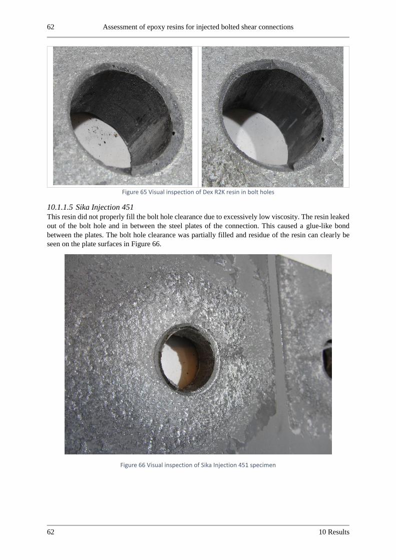
62 Assessment of epoxy resins for injected bolted shear connections
62 10 Results
Figure 65 Visual inspection of Dex R2K resin in bolt holes
10.1.1.5 Sika Injection 451
This resin did not properly fill the bolt hole clearance due to excessively low viscosity. The resin leaked
out of the bolt hole and in between the steel plates of the connection. This caused a glue-like bond
between the plates. The bolt hole clearance was partially filled and residue of the resin can clearly be
seen on the plate surfaces in Figure 66.
Figure 66 Visual inspection of Sika Injection 451 specimen

Assessment of epoxy resins for injected bolted shear connections 63
10 Results 63
10.1.1.6 Sikadur 30
The resin correctly filled all the bolt holes. For reference an image of one of the cover plates is shown.
Here it can be seen that the bolt shank positioning is correct and the most unfavourable position of the
bolt shank is realised according to the EN 1090 test specifications [8]. Again, air inclusions can be seen
in the resin layer. The resin layer and cover plates are shown in Figure 67.
Figure 67 Visual inspection of disassembled Sikadur 30 specimen
10.1.2 Results of initial connection tests The results of these connections tests are shown in Figure 68 and Figure 69. First the load displacement
of the connection is shown for the initial loading. Secondly the creep of the connection is compared after
loading to 90% of the found 0.15 mm slip value. For clarity, the average of the two connections of the
specimen is shown. The full results are tabulated in Table 13.
Figure 68 load-displacement results of initial tests on selected resin products
0
50
100
150
200
250
0.000 0.050 0.100 0.150 0.200
load
[kN
]
displacement [mm]
RenGel_CBG_average
DexG20_CBG_average
DexR2K_CBG_average
Sika Injection451_CBG_average
Sikadur30_CBG_average
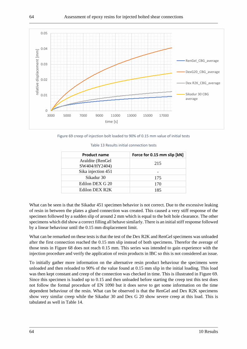
64 Assessment of epoxy resins for injected bolted shear connections
64 10 Results
Figure 69 creep of injection bolt loaded to 90% of 0.15 mm value of initial tests
Table 13 Results initial connection tests
Product name Force for 0.15 mm slip [kN]
Araldite (RenGel
SW404/HY2404) 215
Sika injection 451 -
Sikadur 30 175
Edilon DEX G 20 170
Edilon DEX R2K 185
What can be seen is that the Sikadur 451 specimen behavior is not correct. Due to the excessive leaking
of resin in between the plates a glued connection was created. This caused a very stiff response of the
specimen followed by a sudden slip of around 2 mm which is equal to the bolt hole clearance. The other
specimens which did show a correct filling all behave similarly. There is an initial stiff response followed
by a linear behaviour until the 0.15 mm displacement limit.
What can be remarked on these tests is that the test of the Dex R2K and RenGel specimens was unloaded
after the first connection reached the 0.15 mm slip instead of both specimens. Therefor the average of
those tests in Figure 68 does not reach 0.15 mm. This series was intended to gain experience with the
injection procedure and verify the application of resin products in IBC so this is not considered an issue.
To initially gather more information on the alternative resin product behaviour the specimens were
unloaded and then reloaded to 90% of the value found at 0.15 mm slip in the initial loading. This load
was then kept constant and creep of the connection was checked in time. This is illustrated in Figure 69.
Since this specimen is loaded up to 0.15 and then unloaded before starting the creep test this test does
not follow the formal procedure of EN 1090 but it does serve to get some information on the time
dependent behaviour of the resin. What can be observed is that the RenGel and Dex R2K specimens
show very similar creep while the Sikadur 30 and Dex G 20 show severe creep at this load. This is
tabulated as well in Table 14.
0
0.01
0.02
0.03
0.04
0.05
3000 5000 7000 9000 11000 13000 15000 17000
rela
tive
dis
pla
cem
ent
[mm
]
time [s]
RenGel_CBG_average
DexG20_CBG_average
Dex R2K_CBG_average
Sikadur 30 CBGaverage

Assessment of epoxy resins for injected bolted shear connections 65
10 Results 65
Table 14 Creep results initial connection tests
Resin product Creep deformation
[mm]
Relative deformation*
[%]
RenGel
SW404/HY2404 0.009 0.0
Dex G20 0.042 349.9
Dex R2K 0.011 18.4
Sikadur 30 0.025 169.3
*compared with RenGel SW404/HY2404 creep behavior
10.2 Temperature dependency tests Based on the results of the initial test series the research is continued for RenGel SW404/HY2404,
Edilon Dex R2K, Edilon Dex G20 and Sika Sikadur 30 resin. Sika injection 451 is discarded due to the
resin not properly filling the bolt hole clearance and penetrating the steel plate surfaces.
The investigation into the dependency on curing temperature of the resin was executed in several series
of tests due to errors in execution of the test or assembly of specimens. In this section first the execution
errors and issues will be discussed. Thereafter the results of performed tests without issues will be
reported for analysis.
10.2.1 First series on temperature dependency (T1) These specimens were erroneously assembled hand-tight the same as the initial test series instead of the
prescribed 100 Nm. In this test series, some specimens did not give good results due to issues with the
injection of specimens and because of errors in the execution of the test procedure, aside from the
aforementioned 100 Nm mistake. The specimens with issues are summarized here in Table 15.
Table 15 Issues with test specimens of first series on temperature dependency
Test specimen ID issue
T1_RenG_LD2_8_Zn_100Nm_slip Too little resin mixed for injection. One connection
of this specimen unusable.
T1_sd30_LD2_8_Zn_100Nm_slip Injection failed for 2 bolts. Both in one connection.
One connection unusable results.
T1_RenG_LD2_16_Zn_100Nm_slip Nuts not loosened before testing started
T1_dR2K_LD2_16_Zn_100Nm_slip Nuts not loosened before testing started
T1_sd30_LD2_16_Zn_100Nm_slip Both connections unusable due to failed injection
T1_sd30_LD2_24_Zn_100Nm_slip One connection unusable due to failed injection.
The issues with the injection of Sikadur 30 resin will be discussed in more detail due to the important
information that could be gained from this.

66 Assessment of epoxy resins for injected bolted shear connections
66 10 Results
10.2.2 Temperature dependency retests (T2) To be able to draw conclusions on the curing temperature dependency the tests with issues summarized
above in Table 15 were repeated. To limit the total number of tests performed in this research it was
decided to stop further testing on the Edilon Dex G 20 resin. The strength values found in the first series
on temperature dependency were a lot lower than the other products and this product also showed the
worst time-dependent behavior in the indication gained from the initial test series. In addition to the
retests on the temperature dependency also two additional tests were performed with a different plate
surface preparation. These will be discussed in more detail below.
10.2.3 Third series on temperature dependency (T3) From the results on the different plate surface preparation specimens of test series T2 combined with the
results using the adapted assembly procedure of series DS this series was done to draw a clear conclusion
on the dependency of curing temperature for Dex R2K resin. One specimen in this series had an issue
in this series:
Test specimen ID Issue
T3_dR2K_LD2_24_Zn_30Nm_slipmax_1 LVDT mounting bracket loose
10.2.4 Results From the first series of tests Sikadur-30 showed issues with the injection procedure across all specimens.
The position of the washer was found to influence the resin injection for this product. The bolts for
which injection was not possible in this research were removed from the specimen and the typical pattern
found for these bolts is shown in Figure 70. These issues arose in all specimens of the first series and
based on this behavior the resin was discarded as an alternative.
Figure 70 Sikadur-30 failed injection at bolt head washer interface
The initial test series results are tabulated in Table 16. Based on the results of T1 the Edilon Dex G 20
product was also discarded as an alternative. The strength values in this series were lower than the other
products and the creep behavior of Dex G 20 in the initial tests was also unfavorable compared to the
other products.

Assessment of epoxy resins for injected bolted shear connections 67
10 Results 67
Table 16 Results of first temperature dependency series (T1)
Temperature
[Celsius]
force 0.15 mm top
CBG [kN]
force 0.15 mm
bottom CBG [kN] Average [kN]
Average effective Bearing stress resin
[N/mm^2
RenGel
8 197 - 197 246,25
16 227 203 215 268,75
24 200 197 199 248,125
Dex g 20
8 151 139 145 181,25
16 154 158 156 195
24 159 175 167 208,75
DEX R 2 k
8 229 182 206 256,875
16 234 178 206 257,5
24 172 141 157 195,625
Sikadur 30
8 - 124 124 155
16 - - - -
24 - 154 154 192,5
10.2.5 Friction influence During this research assembly of specimens was done with 100 Nm torque applied to the nut during
assembly. From the results found in the load-slip graphs a stiff initial response of the specimens was
seen. In the second test series done on temperature dependency this stiff response was investigated by
varying the plate surface preparation. An epoxy coated specimen was used which has a very low factor
as shown in research by P.A. de Vries [56]. In Figure 71 the results of specimens cured at 8 degrees with
RenGel are shown in which the only variation is the plate surface preparation. From this it is concluded
that the 100 Nm assembly procedure results in some load transfer through friction between the plate
surfaces. This despite the loosening of nuts before testing. It is theorized here that the resin behaves stiff
enough after curing to retain the preload in the specimen.
Based on this result the assembly procedure was changed to apply only a 30 Nm torque on the nut during
assembly to remove this friction influence in the results.

68 Assessment of epoxy resins for injected bolted shear connections
68 10 Results
Figure 71 Load-slip of RenGel specimen with 100 Nm assembly torque with normal Zinc coated and epoxy low friction coating
10.2.6 Overload behavior The test results reported concern the 0.15 mm slip value of EN 1090 [8]. In this research, the behavior
for higher loads of the resin products is also investigated as described in Figure 56. The load-slip diagram
of test results on Dex R2K at 24 degrees and RenGel at 16 degrees is shown in Figure 72. From this test
procedure, the connections maintain a nearly linear behavior even when loaded far beyond what is
specified in EN 1090. [8] What can be seen in Figure 72 is that the force increases up to a displacement
of 0.6 mm. This is four times the short-term displacement limit from EN-1090.
0
50
100
150
200
250
0 0.03 0.06 0.09 0.12 0.15
load
[kN
]
displacement center bolt group [mm]
RenGel 100 Nm 1
RenGel 100 Nm 2
RenGel low friction coating100 Nm 1
RenGel low friction coating100 Nm 2
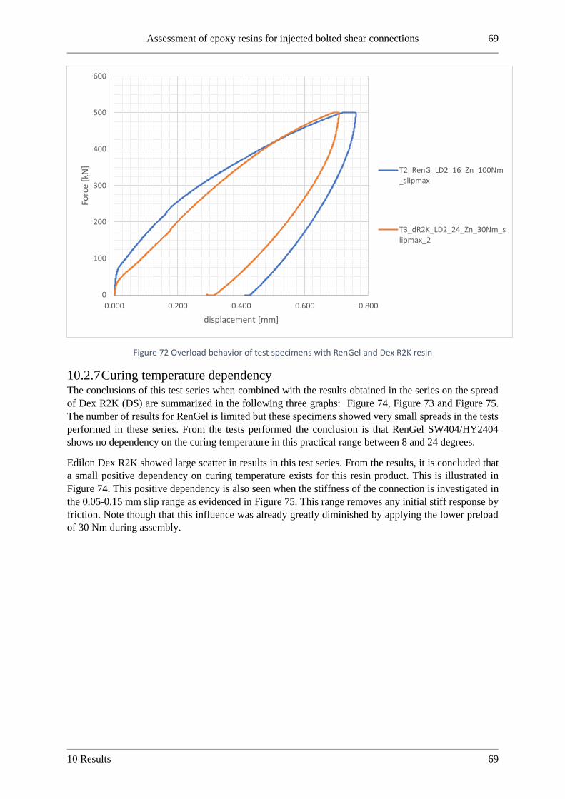
Assessment of epoxy resins for injected bolted shear connections 69
10 Results 69
Figure 72 Overload behavior of test specimens with RenGel and Dex R2K resin
10.2.7 Curing temperature dependency The conclusions of this test series when combined with the results obtained in the series on the spread
of Dex R2K (DS) are summarized in the following three graphs: Figure 74, Figure 73 and Figure 75.
The number of results for RenGel is limited but these specimens showed very small spreads in the tests
performed in these series. From the tests performed the conclusion is that RenGel SW404/HY2404
shows no dependency on the curing temperature in this practical range between 8 and 24 degrees.
Edilon Dex R2K showed large scatter in results in this test series. From the results, it is concluded that
a small positive dependency on curing temperature exists for this resin product. This is illustrated in
Figure 74. This positive dependency is also seen when the stiffness of the connection is investigated in
the 0.05-0.15 mm slip range as evidenced in Figure 75. This range removes any initial stiff response by
friction. Note though that this influence was already greatly diminished by applying the lower preload
of 30 Nm during assembly.
0
100
200
300
400
500
600
0.000 0.200 0.400 0.600 0.800
Forc
e [k
N]
displacement [mm]
T2_RenG_LD2_16_Zn_100Nm_slipmax
T3_dR2K_LD2_24_Zn_30Nm_slipmax_2

70 Assessment of epoxy resins for injected bolted shear connections
70 10 Results
Figure 73 Curing temperature dependency of RenGel SW404/HY2404 results
Figure 74 Curing temperature dependency results of Edilon Dex R2K
100
120
140
160
180
200
220
5 10 15 20 25
forc
e at
0.1
5 m
m s
lip (
kN)
curing temperature (celsius)
RenGel temperature dependancy results
100
120
140
160
180
200
220
5 10 15 20 25
forc
e at
0.1
5 m
m s
lip (
kN)
curing temperature (celsius)
Dex R2K temperature dependancy results

Assessment of epoxy resins for injected bolted shear connections 71
10 Results 71
Figure 75 Stiffness of connection measured in the range 0.05-0.15 mm slip for Dex R2K resin
10.3 Spread of Dex R2K In this series of tests 4 specimens were tested using Edilon Dex R2K resin at 16 degree and a 30 Nm
preload during assembly. The load displacement result of the four specimens is shown in Figure 76.
These results are also tabulated in Table 17. In this series one specimen suffered from an issue. For that
specific specimen one connection gave an unusable result in this case. This is also noted in Table 17.
Figure 76 Load displacement graphs of Dex R2K specimens at 16 degrees
0
200
400
600
800
1000
1200
1400
0 5 10 15 20 25 30
stif
fnes
s [k
N/m
m]
Curing temperature [celsius]
Connection stiffness Dex R2K 30 Nm samples
0
20
40
60
80
100
120
140
160
180
200
0.000 0.050 0.100 0.150 0.200
load
[kN
]
displacement [mm]
DexR2K 16 degree 1
DexR2K 16 degree 2
DexR2K 16 degree 3
DexR2K 16 degree 4

72 Assessment of epoxy resins for injected bolted shear connections
72 10 Results
Table 17 Test results of spread Dex R2K test series
Test specimen ID connectio
n
resistanc
e at 0.15
mm [kN]
resin
effective
stress
[N/mm^2
]
Connection
stiffness *
[kN/mm]
DS_dR2K_LD2_16_Zn_30Nm_slipmax
_1
1 163 203.75 855.96126
DS_dR2K_LD2_16_Zn_30Nm_slipmax
_1
2 156 195 895.52593
DS_dR2K_LD2_16_Zn_30Nm_slipmax
_2
1 161 201.25 868.03147
DS_dR2K_LD2_16_Zn_30Nm_slipmax
_2
2 154 192.5 905.96659
DS_dR2K_LD2_16_Zn_30Nm_slipmax
_3
1 150 187.5 719.7442
DS_dR2K_LD2_16_Zn_30Nm_slipmax
_3
2 131 163.75 813.02313
DS_dR2K_LD2_16_Zn_30Nm_slipmax
_4
1** - - -
DS_dR2K_LD2_16_Zn_30Nm_slipmax
_4
2 127 158.75 841.77556
*connection stiffness determined in the range of 0.07 to 0.15 mm slip of CBG
** LVDT bracket was loose during testing. Results unusable.
The spread of the Dex R2K specimens of this test series and the specimens tested using the same 30 Nm
preload method from test series T3 is illustrated in Figure 77. What can be seen is that the spread of this
product is very large. This in contrast to the spread found using RenGel SW404/HY2404 illustrated in
Figure 73. This analysis of the spread is done using the results with the 30 Nm Preload assembly so
scatter caused by friction effects is not a factor in the results displayed here.
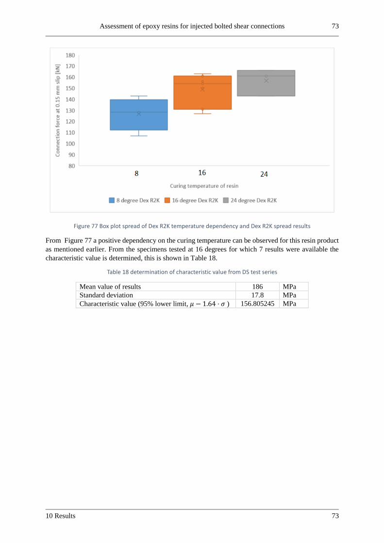
Assessment of epoxy resins for injected bolted shear connections 73
10 Results 73
Figure 77 Box plot spread of Dex R2K temperature dependency and Dex R2K spread results
From Figure 77 a positive dependency on the curing temperature can be observed for this resin product
as mentioned earlier. From the specimens tested at 16 degrees for which 7 results were available the
characteristic value is determined, this is shown in Table 18.
Table 18 determination of characteristic value from DS test series
Mean value of results 186 MPa
Standard deviation 17.8 MPa
Characteristic value (95% lower limit, 𝜇 − 1.64 ⋅ 𝜎 ) 156.805245 MPa
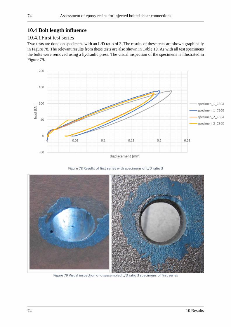
74 Assessment of epoxy resins for injected bolted shear connections
74 10 Results
10.4 Bolt length influence
10.4.1 First test series Two tests are done on specimens with an L/D ratio of 3. The results of these tests are shown graphically
in Figure 78. The relevant results from these tests are also shown in Table 19. As with all test specimens
the bolts were removed using a hydraulic press. The visual inspection of the specimens is illustrated in
Figure 79.
Figure 78 Results of first series with specimens of L/D ratio 3
Figure 79 Visual inspection of disassembled L/D ratio 3 specimens of first series
-50
0
50
100
150
200
0 0.05 0.1 0.15 0.2 0.25
load
[kN
]
displacement [mm]
specimen_1_CBG1
specimen_1_CBG2
specimen_2_CBG1
specimen_2_CBG2

Assessment of epoxy resins for injected bolted shear connections 75
10 Results 75
Table 19 Summary of test results on L/D ratio 3 specimens of first series
Test specimen ID Connectio
n
Resistanc
e at 0.15
mm [kN]
resin
effective
stress
[N/mm^2]
Connection
stiffness *
[kN/mm]
BL1_RenG_LD3_amb_Gb_30Nm_slip_1
1 105 175 602
BL1_RenG_LD3_amb_Gb_30Nm_slip_1
2 115 191 639
BL1_RenG_LD3_amb_Gb_30Nm_slip_2
1 112 186 635
BL1_RenG_LD3_amb_Gb_30Nm_slip_2
2 111 185 619
*connection stiffness determined in the range of 0.07 to 0.15 mm slip of CBG
The results of the specimens with an L/D ratio of 4 in the first series are shown in the same manner as
for the L/D ratio 3 specimens. In Figure 81 The visual inspection of the resin layer in the specimens is
shown after disassembly. In Figure 80 The test results are shown graphically and finally these results
are summarized in Table 20.
Figure 80 Results of first test series on specimens of L/D ratio 4
-50
0
50
100
150
200
0 0.05 0.1 0.15 0.2 0.25
load
[kN
]
displacement [mm]
specimen_1_CBG1
specimen_1_CBG2
specimen_2_CBG1
specimen_2_CBG2

76 Assessment of epoxy resins for injected bolted shear connections
76 10 Results
Figure 81 Visual inspection of resin layer of L/D ratio 4 of first series
Table 20 Summary of test results on L/D ratio 4 specimens in first series
Test specimen ID Connectio
n
Resistanc
e at 0.15
mm [kN]
resin
effective
stress
[N/mm^2]
Connection
stiffness *
[kN/mm]
BL1_RenG_LD4_amb_Gb_30Nm_slip_1
1 124 155 640
BL1_RenG_LD4_amb_Gb_30Nm_slip_1
2 119 148 643
BL1_RenG_LD4_amb_Gb_30Nm_slip_2
1 121 151 615
BL1_RenG_LD4_amb_Gb_30Nm_slip_2
2 118 147 612
*connection stiffness determined in the range of 0.07 to 0.15 mm slip of CBG
From the visual inspection as illustrated in Figure 81 and Figure 83 it was observed that resin penetrated
from the bolt hole in between the steel plates. The test results shown in Figure 78 and Figure 80 show
the influence of this with jumps in the displacement. The small resin layer in between the steel plates
caused a glue bond which audibly broke during testing. This resulted in sudden slip in the connection
when the resin bond failed. The resin flowing in between the plates is attributed to the 30 Nm preload
applied to prevent friction is too low for the longer plate packages to close the gap between the plates.
It is noted though that after breaking of the resin bond all force must be transferred by bearing. Further
The bond already breaks at relatively low force so the influence of this resin layer between the plates is
thought to be minor on the 0.15 mm slip resistance.
Furthermore, some air inclusions were observed in the resin layer from the visual inspection after
disassembly. These can also be seen in Figure 81 and Figure 83..

Assessment of epoxy resins for injected bolted shear connections 77
10 Results 77
10.4.2 Second test series A second test series is performed to investigate the influence of the L/D ratio. These tests were done by
cleaning the plate material from the first series through sand blasting the surfaces of the plates and
cleaning the bolt holes with a drill of the same size as the bolt hole. In this second series, the preload
applied during assembly, injection and curing of the specimen was changed from 30 Nm to 60 Nm.
Again the results are represented graphically in Figure 82, an overview of the results can also be found
in Table 21. Finally, the visual inspection of the specimens in this second series is shown in Figure 83.
Figure 82 Test results of L/D ratio 3 specimens in second series
Table 21 Overview of test results of second test series on L/D ratio 3 specimens
Test specimen ID Connection Resistance at 0.15 mm [kN]
resin effective
stress [N/mm^2]
connection stiffness* [kN/mm]
BL2_RenG_LD3_amb_Gb_60Nm_slip_1 1 108 179 587
BL2_RenG_LD3_amb_Gb_60Nm_slip_1 2 99 164 569
BL2_RenG_LD3_amb_Gb_60Nm_slip_2 1 98 164 576
BL2_RenG_LD3_amb_Gb_60Nm_slip_2 2 94 157 563
*connection stiffness determined in the range of 0.07 to 0.15 mm slip of CBG
-50
0
50
100
150
200
0 0.05 0.1 0.15 0.2 0.25
load
[kN
]
displacement [mm]
specimen_1_CBG1
specimen_1_CBG2
specimen_2_CBG1
specimen_2_CBG2

78 Assessment of epoxy resins for injected bolted shear connections
78 10 Results
Figure 83 Visual inspection of specimens in the second series on L/D ratio 3
Tests on specimens with an L/D ratio of 4 were also repeated in this second series using the same method
of 60 Nm preload during assembly and cleaning the surfaces by sand blasting them and drilling the bolt
hole to clean it. As before the results are shown graphically in Figure 84, after testing the specimens
were disassembled and the resin layer in the bolt holes was investigated. This is shown in Figure 85.
Finally, the relevant test data is tabulated in Table 22. Note that in this case a sudden jump in
displacement occurred in the 0.07 to 0.15 mm range which is used to determine the connection stiffness.
So for one specimen these values are not calculated.
Figure 84 Results of L/D ratio 4 specimens in second test series
-50
0
50
100
150
200
0 0.05 0.1 0.15 0.2 0.25
load
[kN
]
displacement [mm]
specimen_1_CBG1
specimen_1_CBG2
specimen_2_CBG1
specimen_2_CBG2

Assessment of epoxy resins for injected bolted shear connections 79
10 Results 79
Table 22 Overview of test results of L/D ratio 4 specimens in second series
Test specimen ID Connection Resistance at 0.15 mm [kN]
resin effective
stress [N/mm^2]
connection stiffness* [kN/mm]
BL2_RenG_LD4_amb_Gb_60Nm_slip_1 1 105 131 -**
BL2_RenG_LD4_amb_Gb_60Nm_slip_1 2 98 123 -**
BL2_RenG_LD4_amb_Gb_60Nm_slip_2 1 100 125 563
BL2_RenG_LD4_amb_Gb_60Nm_slip_2 2 101 126 597 *connection stiffness determined in the range of 0.07 to 0.15 mm slip of CBG
** connection stiffness of this specimen is not calculated due to sudden jump in displacement in the
0.07-0.15 mm range
Figure 85 Visual inspection of resin layer after disassembly of L/D ratio 4 specimens in second series
10.4.3 Visual inspection Again, the resin has run between the plate surfaces of the connection. This resulted once more in jumps
in the displacement during testing when an audible breaking of the resin layer bond occurred. Increasing
the preload of specimens during assembly in this case was not sufficient to prevent this from occurring.
It is thought the plate preparation could be a reason for the leaking of resin between the plates as this
did not occur in the previous test series. Finally, in this second test series large air inclusions are visible
in all specimens during the visual inspection.
10.4.4 Measurement setup discussion The results in this section are reported at the CBG. These specimens were tested in the second test
machine setup. Therefore, as explained in section 9 the slip was measured using 4 LVDTs which
measure at the plate edge of the cover plate. To determine from this measurement data the slip in the
CBG the elastic elongation of the center plate must be considered.
This is done by calculating the strain in the center plate and using the length between the LVDT
measurement bracket and the CBG to determine the total deformation of the plate. This is then subtracted
from the measurements at the PE to determine the CBG measurement which can be compared against
the previous results which did measure directly at the CBG.

80 Assessment of epoxy resins for injected bolted shear connections
80 10 Results
An illustration of this procedure is shown below using the BL1_RenG_LD3_amb_Gb_30Nm_slip_2
specimen as an example. The plate geometry of this specimen is reported already in Figure 45. The
young’s modulus used for the plate is 210.000 𝑁/𝑚𝑚2. Further the sensitivity in the results for this
calculation is checked by varying the length over which the plate deformation is taken into account by
+/- 20% and the impact of the calculated resistance.
𝜎𝑝𝑙𝑎𝑡𝑒 = 𝐸 ⋅ 𝜖𝑝𝑙𝑎𝑡𝑒
𝜎𝑝𝑙𝑎𝑡𝑒 =𝐹
𝐴𝑝𝑙𝑎𝑡𝑒=
𝐹
100 ⋅ 30
𝜖𝑝𝑙𝑎𝑡𝑒 =𝐹
100 ⋅ 30 ⋅ 𝐸
∆𝑙𝑝𝑙𝑎𝑡𝑒 =𝐹 ⋅ 𝑙𝐶𝐵𝐺
100 ⋅ 30 ⋅ 𝐸
𝑙𝐶𝐵𝐺 = 60 + 35 = 95 𝑚𝑚
∆𝑙𝑝𝑙𝑎𝑡𝑒 =𝐹 ⋅ 95
100 ⋅ 30 ⋅ 210.000= 1.5 ⋅ 10−7 ⋅ 𝐹
In Table 23 The sensitivity analysis of the plate deformation length is shown for
BL1_RenG_LD3_amb_Gb_30Nm_slip_2. Here the resistance at 0.15 mm slip for the CBG is shown
with the length over which the plate elongation is considered varied by 20% up and down from the actual
length of 95 mm. As can be seen the large variation in plate elongation length has a minor influence on
the calculated resistance at 0.15 mm. therefore it is concluded that this method of processing the results
to the CBG of the specimen is valid.
Table 23 sensitivity analysis of plate deformation length for calculated CBG displacement of specimen LD3_2
Length of plate deformation
𝑙𝐶𝐵𝐺
Resistance at 0.15 mm slip for
connection 1 and 2 [kN]
Difference in resistance
compared to 𝑙𝐶𝐵𝐺 of test
specimen geometry [%]
95 111.635 -*
111.183 -*
76 109.755 -1.68
109.226 -1.76
114 113.833 1.97
113.268 1.46
*THIS CORRESPONDS TO THE SPECIMEN GEOMETRY

Assessment of epoxy resins for injected bolted shear connections 81
10 Results 81
10.4.5 Comparison of test series results Both test series showed the same behavior of resin leaking between the plates despite a change in
preload. Comparing the results of the two test series is done in Figure 86. What can be observed is that
the apparent spread is larger for the test results with an L/D ratio 3 than those specimens with an L/D
ratio of 4. Furthermore, in the first test series we see a trend of increasing capacity between L/D ratio 3
and 4 while this trend is not observed in the second series.
The average strength values of the specimens decreases roughly 20% between the first and second test
series. From the visual inspection of the specimens the second series showed large air inclusions. The
first series air inclusions were also seen but smaller than those of the second series. Despite these air
inclusions though the spread in results that was observed in the first and second series does not change.
This is especially well illustrated in the L/D ratio 4 specimens where both the first and second series of
tests has a small spread.
This could be explained by the fact that specimens are assembled in one batch for each series leading to
a maintained spread between the specimens of one series.
Figure 86 Comparison of test results of bolt length influence series with previous test results
Comparing these results against the calculation method of EN 1993-1-8 [41] and effective bearing length
of 3 is prescribed for the calculated resistance. This means the connection capacity according to the
Eurocode is constant for L/D values of 3 and higher. In these tests, we see that this could be conservative
as indicated by the first series. In the second series, the constant resistance for L/D values larger than 3
is reproduced here.
0
20
40
60
80
100
120
140
1 1.5 2 2.5 3 3.5 4 4.5 5
load
[kN
]
L/D ratio of connection
resistance at 0.15 mmfirst long bolt series
resistance at 0.15 mmsecond long bolt series
resistance at 0.15 mmtemperaturedependancy tests
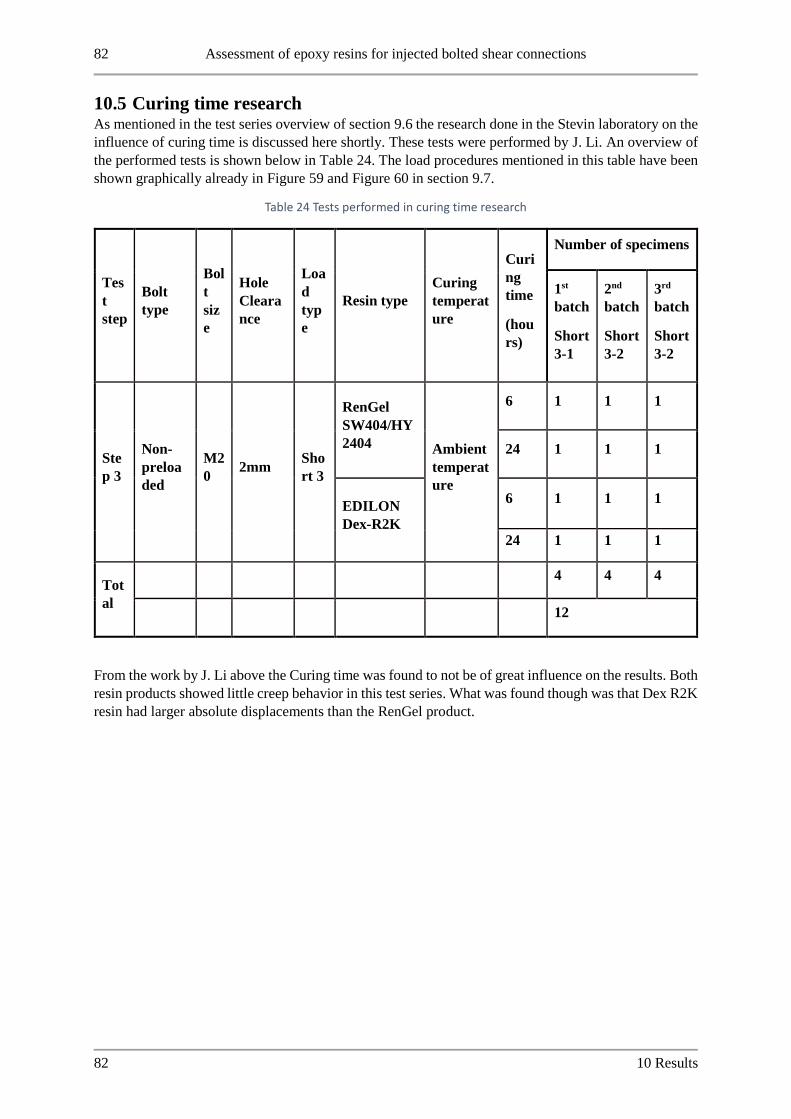
82 Assessment of epoxy resins for injected bolted shear connections
82 10 Results
10.5 Curing time research As mentioned in the test series overview of section 9.6 the research done in the Stevin laboratory on the
influence of curing time is discussed here shortly. These tests were performed by J. Li. An overview of
the performed tests is shown below in Table 24. The load procedures mentioned in this table have been
shown graphically already in Figure 59 and Figure 60 in section 9.7.
Table 24 Tests performed in curing time research
Tes
t
step
Bolt
type
Bol
t
siz
e
Hole
Cleara
nce
Loa
d
typ
e
Resin type
Curing
temperat
ure
Curi
ng
time
(hou
rs)
Number of specimens
1st
batch
Short
3-1
2nd
batch
Short
3-2
3rd
batch
Short
3-2
Ste
p 3
Non-
preloa
ded
M2
0 2mm
Sho
rt 3
RenGel
SW404/HY
2404 Ambient
temperat
ure
6 1 1 1
24 1 1 1
EDILON
Dex-R2K
6 1 1 1
24 1 1 1
Tot
al
4 4 4
12
From the work by J. Li above the Curing time was found to not be of great influence on the results. Both
resin products showed little creep behavior in this test series. What was found though was that Dex R2K
resin had larger absolute displacements than the RenGel product.

Assessment of epoxy resins for injected bolted shear connections 83
10 Results 83
10.6 Linking material properties to performance From all the test results in this research the following analysis of the material properties as it relates to
the performance in injection bolts can be done.
10.6.1 Viscosity of mixed resin product The main determinant of the resin injectability found in this research is the viscosity of the resin after
mixing. From the range of products tested here an indication of the viscosity of product necessary for
injection in injection bolts can be given. A definitive lower bound of the viscosity can be given by the
Sika Injection 451. This resin viscosity was decisively too low for this application.
The injection of Sikadur 30 on the other hand was not possible. This product has no supplied viscosity
in the PDS to reference. [52] What can be mentioned is that this product was the only one which did not
behave as a liquid after mixing. It cannot be poured and is best characterized as a paste rather than a
liquid.
Both Edilon resin products showed proper filling of the bolt hole cavity in this research. The Dex G 20
specimens though did have some small leaking of resin from the injection port and air escape washer
after injection. This was solved with modelling clay.
Finally, a remark is made about the RenGel SW404/HY2404 product currently applied in practice. In
the PDS it is remarked that this resin mixture shows thixotropic behavior. [24] Thixotropic fluids have
a time-dependent viscosity. Their apparent viscosity lowers when the fluid is stressed through stirring
for example. This implies that this resin product has a lower viscosity during the injection when it is
stressed and flowing and becomes more viscous after injection is stopped. This could be a favorable
property of the product as this facilitates good filling of the cavity while limiting any leaking of resin
after injection is stopped.
Table 25 Summary of supplied viscosities and result of application for IBC
Product Supplied viscosity Result of application in
injection bolts
remarks
Sikadur 30 Not supplied in PDS Issues with injection
around washer of bolt
head
Paste. Does not flow
as a liquid
Sika Injection 451 100 𝑚𝑃𝑎 ⋅ 𝑠 at 23
degrees
No proper filling of bolt
hole cavity. Leaked
between plates
Edilon Dex R2K 35 𝑃𝑎 ⋅ 𝑠 (measured
after 2 minutes at 26
degrees Celsius)
Proper filling
Edilon Dex G20 11 𝑃𝑎 ⋅ 𝑠 (measured
at 25 degrees)
Proper filling but some
leaking from injection
port. Clay needed
RenGel SW404/HY2404 55 − 80 𝑃𝑎 ⋅ 𝑠 of
resin.
3.5 − 5.5 𝑃𝑎 ⋅ 𝑠 of
hardener
Proper filling Thixotropic:
Apparent viscosity
lowers when
agitated

84 Assessment of epoxy resins for injected bolted shear connections
84 10 Results
10.6.2 Mechanical properties of resin products The resin products applied in this research have mechanical properties supplied in the PDS. These
mechanical properties which are supplied are derived using different test methods. A comparison
between the supplied mechanical properties and the effective bearing stresses found in the double lap
shear tests of injection bolts with the specific product is shown in Table 26. What can be concluded from
this comparison is that the relation between the supplied compressive strength of the resin products does
not show a clear correlation with the performance in the IBC application.
Table 26 comparison of supplied mechanical properties in PDS with bearing stress in injection bolts
Product Supplied
compressive strength
Bearing stress in
injection bolts
remarks
Sikadur 30 54 𝑀𝑃𝑎 155-193 MPa (T1) ASTM- D695
Sika Injection 451 70 − 80 𝑀𝑃𝑎 - Test method
unspecified
Edilon Dex R2K 100 𝑀𝑃𝑎 after 24
hours
158-204 MPa (DS) ISO 604
Edilon Dex G20 > 90 𝑀𝑃𝑎 180-209 MPa (T1) EN 196-1
RenGel SW404/HY2404 110 − 125 𝑀𝑃𝑎 248-269 MPa (T1) ISO 604

Assessment of epoxy resins for injected bolted shear connections 85
11 Modelling of resin stress for long bolts 85
11 Modelling of resin stress for long bolts To gain a better understanding of the mechanical behavior of the resin products in injection bolts an
analytical model was developed to model the stress distribution that occurs in the resin layer when the
injection bolt connection is loaded. In this chapter the development and results of the model are
discussed.
11.1 Model overview and assumptions The model developed in this research is based on an injection bolt in a double lap shear connection. This
aligns with the state of the art in terms of numerical modeling of injection bolts. [10] [32] Furthermore
the test procedure and guidelines explained in the standards of EN 1090 and EN 1993-1-8 are related to
double lap shear connections. [8] [41]
Of interest in the development of this model is the behavior of the resin layer stress in longer connections.
This is taken into account in the guidelines of EN 1993-1-8 through an effective bearing stress. The
analytical model attempts to model the stress peak distribution as seen in the left of Figure 87.
Figure 87 Resin layer stress distribution in long injection bolts [5]
An analytical modelling approach was followed to investigate the resin layer stress for this research. As
stated in the ECCS recommendations the cause of the uneven bearing stress as illustrated in Figure 87
is caused by bending of the bolt for longer connections. [5]
Based on the considerations above the analytical model schematization of an injection bolt in a double
lap shear connection is derived and presented in Figure 88.
Figure 88 Analytical schematization of resin-injected bolt of double lap shear connection
The most important points of this schematization are discussed separately below.

86 Assessment of epoxy resins for injected bolted shear connections
86 11 Modelling of resin stress for long bolts
11.1.1.1 Deformation of bolt
To model the stress that occurs in the resin layer the bending of the bolt should be taken into account
according to the ECCS recommendations [5]. For this deformation of the bolt a beam model is used.
The L/D ratio of the connection is the most important parameter for this beam model. The cut off for the
effective bearing thickness of the resin layer as laid down in EN 1993-1-8 is at an L/D ratio of 3. For
such low span to depth ratios an analytical approach should take into account both the bending and shear
deformation of a beam. Therefore, the analytical modeling of deformations of the bolt is done using
Timoshenko Theory [60] [61].
11.1.1.2 Deformation of steel plates
Due to the lower stiffness of resin products compared to the steel plates it is assumed for this analytical
model that the plates are rigid. No deformation of the plate and bolt hole is considered in this analytical
model.
11.1.1.3 Resin layer
To comply with the tests as performed in this research project the bolt is assumed to be placed in the
bolt hole in the most unfavorable position as illustrated in Figure 89. Therefore, only resin is located at
the compressed side.
Figure 89 Assumed unfavorable positioning of bolt in the bolt hole
The resin layer in the injection bolt is connected at the outer edge to the bolt hole in the steel plate and
at the inner edge to the bolt shank. To model this resin layer, a set of distributed springs is chosen which
are placed at opposite sides of the bolt shank for the cover and center plates respectively. The distributed
springs are attached to a fixed support which represents the bolt hole and steel place which as explained
above are assumed to be rigid.
The spring characteristic used for the resin layer in this model is assumed to be linear elastic. This is
based on the test results presented in this research which shows the connections have a nearly linear load
slip behavior even far beyond the maximum slip value of 0.15 mm from EN 1090. This model does not
consider the visco-elastic properties of the resin which cause creep for longer time durations.
11.1.1.4 Bolt head, washer and nut
The model boundary is placed at the outer edges of the cover plate. The bolt head and nut are taken into
account in this analytical model through the boundary conditions. It is assumed that through the bolt and
nut being tightened and in contact with the plate surface they prevent rotation of the bolt shank occurring
in the boundary. Thus, the boundary of the model is a clamped support at the outer edges of the cover
plates. Further it is assumed that no vertical forces are transferred from the bolt head and nut to the bolt
shank. Thus no vertical forces can be transferred to the boundary.

Assessment of epoxy resins for injected bolted shear connections 87
11 Modelling of resin stress for long bolts 87
11.1.1.5 Loading of model
To compare the model results to experimentally derived values the loading applied to the model
corresponds to the short duration resistance of the connection according to the test procedure of Annex
G EN 1090. This means a slip between the cover and center plates of 0.15 mm must occur.
The force in a double lap shear specimen is introduced through the steel plates of the connection. The
loading of this model is done in a displacement controlled manner to guarantee the slip value of the
procedure. The plates which are assumed to be rigid in the model are taken into account by the rigid
support of the distributed springs. A prescribed displacement of this rigid support is used to load the
model and generate the resin stress in the bolt.
11.2 Derivation of analytical relations From the schematization as shown in Figure 88 Timoshenko theory has been used to derive a set of
analytical equations which govern the deflection of the bolt shank following the examples of A. Simone
[62]. For a full explanation of the derivation of these analytical equations please refer to Appendix A
.
𝐺𝐴𝑠 ⋅ (𝑑2𝑣
𝑑𝑥2−
𝑑𝜙
𝑑𝑥) = −𝑞 + 𝑘 ⋅ (𝑣 − 𝑤)
−𝐸𝐼 ⋅𝑑2𝜙
𝑑𝑥2= 𝐺𝐴𝑠 ⋅ (
𝑑𝑣
𝑑𝑥− 𝜙)
These two equations are a set of linear coupled differential equations. To solve a set of differential
equations boundary conditions are necessary. These have already been explained above so are only
shown here briefly. Again, refer to the appendix for a full description of the derivation.
Table 27 Overview of boundary conditions of the model
𝑥 = 0 𝑥 = 𝑡1 + 2 ⋅ 𝑡2
Shear force 𝑉 0 0
Rotation of beam 𝜙 0 0
11.3 Solving analytical model To solve the set of equations presented in section 11.2 no closed form solution could be found by
hand. Therefore, MATLAB is used to derive a solution to the set of equations. To solve a set of
linearly coupled differential equations, the built-in solver application of MATLAB BVP4C is used.
[63] [64] An example solution for a similar problem is given in research. [65] A full derivation and
application of MATLAB solver BVP4C to solve the model presented here is discussed in Appendix A

88 Assessment of epoxy resins for injected bolted shear connections
88 11 Modelling of resin stress for long bolts
11.3.1 Model parameters The model presented above is applied in first instance with parameters that align with the test specimen
geometry outlined by EN 1090 [8]. These geometrical values are:tabulated in Table 28.
Table 28 Model parameters used in analytical modelling
Parameter Value Unit
Hole clearance 2 𝑚𝑚
Bolt size M20 𝑚𝑚
Young’s modulus of steel 210.000 𝑁/𝑚𝑚2
Connection slip 0.15 𝑚𝑚
Poisson ratio of steel 0.28 - Ratio plate thicknesses 𝑡1/𝑡2 2 -
As shown in the analytical relations that govern the deflections of the bolt the parameters relating to the
cross-section of the bolt shank must be defined. For this use is made of the mechanical relations relating
to a circular cross-section. Note that it is assumed that no threaded parts are inside the connection.
𝐼 = 𝜋 ⋅𝑟4
4
Further the shear modulus must be determined, for this the following holds:
𝐺 =𝐸
2 ⋅ (1 + 𝜈)
The used young’s modulus and Poisson ratio are tabulated above in Table 28. The parameter 𝑘 of the
distributed spring stiffness is dependent on the chosen value of the Young’s modulus of the resin
product. This parameter is used to calibrate the model and will be discussed in the next section. For
reference the relation between 𝑘 and 𝐸𝑟𝑒𝑠𝑖𝑛 is derived here per unit length:
𝜎 = 𝐸𝑟𝑒𝑠𝑖𝑛 ⋅ 𝜖
𝜖𝑟𝑒𝑠𝑖𝑛 =∆𝑙
𝑙
𝐹 = 𝜎 ⋅ 𝐴 = 𝜎 ⋅ 1 ⋅ 𝐷𝑏𝑜𝑙𝑡
𝐹 = 𝐸𝑟𝑒𝑠𝑖𝑛 ⋅∆𝑙
𝑙⋅ 1 ⋅ 𝐷𝑏𝑜𝑙𝑡
𝐹 =𝐸𝑟𝑒𝑠𝑖𝑛 ⋅ 𝐷𝑏𝑜𝑙𝑡
ℎ𝑜𝑙𝑒 𝑐𝑙𝑒𝑎𝑟𝑎𝑛𝑐𝑒⋅ ∆𝑙
∆𝑙 = 𝑣 + 𝑤
𝐹 = 𝑘𝑟𝑒𝑠𝑖𝑛 ⋅ (𝑣 + 𝑤)
𝑘𝑟𝑒𝑠𝑖𝑛 =𝐸𝑟𝑒𝑠𝑖𝑛 ⋅ 𝐷𝑏𝑜𝑙𝑡
ℎ𝑜𝑙𝑒 𝑐𝑙𝑒𝑎𝑟𝑎𝑛𝑐𝑒

Assessment of epoxy resins for injected bolted shear connections 89
11 Modelling of resin stress for long bolts 89
11.4 Model analysis and calibration The model behavior is analyzed in this section with an initial estimate for the resin Young’s modulus
from literature of 𝐸𝑟𝑒𝑠𝑖𝑛 = 500 𝑁/𝑚𝑚2. [10] This is related to the resin product RenGel
SW404/HY2404. Due to the results found in earlier test series on Dex R2K showing large spread the
tests on bolt length were only performed for RenGel so the modelling is done using this resin. The
calibration explained in this chapter on test results can also be performed for Dex R2K resin.
The model is used to derive a solution to the specified slip of 0.15 mm for connections with an L/D ratio
up to 10. To achieve this the plate package length was increased at every step while the bolt dimensions
were kept constant. The ratio between center and cover plates was also kept constant in this analysis.
11.4.1 Qualitative analysis of resin stress distribution The main varied parameter in the initial run of the model concerns the L/D ratio. As the bolt bending
deformation is assumed to largely be responsible for the uneven stress distribution it is expected that the
resin stress shows larger peak stresses as the L/D ratio increases and a near constant behavior for low
L/D ratio where the force is mostly transferred through shear. The resulting stress distribution over the
length of the connection is illustrated in the following 3 figures:
Figure 90 Resin stress distribution over length of connection for L/D ratio of 1

90 Assessment of epoxy resins for injected bolted shear connections
90 11 Modelling of resin stress for long bolts
Figure 91 resin stress distribution over length of connection for L/D ratio 2
Figure 92 Resin stress distribution for L/D ratio 5

Assessment of epoxy resins for injected bolted shear connections 91
11 Modelling of resin stress for long bolts 91
From this initial run, erroneous behavior was seen for L/D ratios larger than 6. The resin stress calculated
by the analytical model had tension in the center of the center plate and outer of the outer plates. To
remedy this behavior in the model the resin distributed spring stiffness was given a bi-linear
characteristic that does not allow any tension. This assumes no tensile forces can be transferred in the
resin layer due to adhesion to the bolt hole surface. The resulting resin stress distribution using this bi-
linear spring stiffness is shown for an L/D ratio of 7 in Figure 93.
Figure 93 Resin stress distribution with bi-linear spring stiffness to eliminate tension
From the resin stresses shown in Figure 90 through to Figure 93 the trend of the model behavior appears
to follow what is expected to happen in these connections. As already mentioned the tensile stresses
occurring in the resin layer had to be solved manually using a tensile stress cutoff in the resin spring
stiffness.
What can be remarked is that the resin stress trend appears to correlate well with what is expected the
absolute values show a peculiar behavior. The peak stress that is found in the resin layer occurring in
the interface between center and cover plates is independent of the L/D ratio. The value that is found
here is directly related to the applied displacement of 0.15 mm in the model. This is calculated below:
𝑤 = 0.15 𝑚𝑚
𝑤 = 𝑤1 + 𝑤2 = 0.075 + 0.075 𝑚𝑚
𝜎 = 𝐸𝑟𝑒𝑠𝑖𝑛 ⋅ 𝜖𝑟𝑒𝑠𝑖𝑛
𝜎 = 5000 ⋅𝑤1
ℎ𝑜𝑙𝑒 𝑐𝑙𝑒𝑎𝑟𝑎𝑛𝑐𝑒
𝜎 = 5000 ⋅0.075
2= 187.5 𝑀𝑃𝑎

92 Assessment of epoxy resins for injected bolted shear connections
92 11 Modelling of resin stress for long bolts
What happens is the model is that this calculated value appears as an absolute maximum and the average
stress drops through a lowering of the resin stress away from the center and cover plate interface. This
is illustrated in the following graph shortly:
Figure 94 Relation between peak and average stress of resin layer in analytical model
A further analysis of the model behavior is the force balance of the connection. As stated in the model
overview the bolt in the connection is assumed to be in force equilibrium without vertical reaction forces
occurring in the bolt head and nut interface at the outside of the cover plates. This also to verify the
solution derived using the BVP4C package in MATLAB is correct. From Table 29 the solutions found
have a very small residual that is probably caused by the solution method in BVP4C.
Table 29 Force balance residuals of model results
L/D ratio Force outer plates
[kN]
Force center plate
[kN]
Residual [kN]
1 36.7499 36.7498 1.88 ⋅ 10−5
2 67.5796 67.5794 1.88 ⋅ 10−4
3 83.9395 83.9388 7.24 ⋅ 10−4
4 84.2799 94.2783 0.0017
5 77.4595 77.4567 0.0028
6 71.0809 71.0774 0.0036
7 66.7959 66.8113 0.0154
8 63.6808 63.6986 0.0178
9 61.4812 61.498 0.0169
10 60.0516 60.0602 0.0086

Assessment of epoxy resins for injected bolted shear connections 93
11 Modelling of resin stress for long bolts 93
Following this initial run, the connection resistance at the 0.15 mm slip value from EN 1090 according
to the analytical model can be plotted. This is shown in Figure 95. What can be seen from this result is
that the model shows a peak capacity at an L/D ratio of 3.5. In the current regulations the maximum
capacity of an IBC is reached at an L/D ratio of 3 and the capacity remains constant afterwards. This
result implies that the peak capacity is reached for slightl higher L/D ratios. Remarkably this model
suggest that the resistance at 0.15 mm for higher L/D ratios does not remain constant but actually
drops.
Figure 95 Connection resistance at 0.15 mm for different L/D ratio values

94 Assessment of epoxy resins for injected bolted shear connections
94 11 Modelling of resin stress for long bolts
11.4.2 Calibration of model using test results For the initial analysis an E modulus found from literature is used. This is compared against the values
found in the Temperature dependency tests performed for this research on RenGel SW404/HY2404
resin. The test results are then used to calibrate the model through adaptation of the Young’s modulus
of the resin. This procedure resulted in an adapted resin Young’s modulus of 7500 N/mm^2.
A comparison between the test results of temperature dependency and the analytical model calculated
resistance with this calibrated Young’s modulus is shown in Figure 96
Figure 96 Model results using calibrated Young's Modulus

Assessment of epoxy resins for injected bolted shear connections 95
11 Modelling of resin stress for long bolts 95
11.5 Verification of model
11.5.1 FEM model To verify the calibrated model behavior for this research this author cooperated with M.P. Nijgh who
developed a FEM model for injection bolts. [32] The stress distribution of the models is compared by
normalizing them. An overview of this comparison between the two models is given in Figure 97. From
this verification it is concluded that the bolt bending is accurately calculated in the analytical model for
all L/D ratios [32]. As can be seen in Figure 97 the analytical model solution diverges from the FEM
results for L/D values around 4. The agreement between the models gets worse as the L/D ratio increases
further with the analytical results dropping to zero not occurring in the FEM model.
From this verification of the model it is concluded that the analytical model does not work for L/D ratios
larger than 4.
Figure 97 Comparison between FEM results and analytical model [32]

96 Assessment of epoxy resins for injected bolted shear connections
96 11 Modelling of resin stress for long bolts
11.5.2 Verification against test results The model is also checked against the test results obtained on long bolt specimens tested in this research.
For this again the calibrated analytical model is used. An overview of both long bolt test series results
is shown in Figure 98. The model is calibrated using the test results on L/D ratio 2. These are shown in
aforementioned graph for reference.
What can be seen is that the test results of the first test series appear to have a good agreement with the
calculated maximum capacity of the analytical model. This is not the case for the second series of tests.
As mentioned in the discussion of these test results the air inclusions observed could influence the
differences between the results of each series. Comparison of these test results with the analytical model
is inconclusive. The differences between the model and test results are large and different for the two
series. The apparent Young’s modulus that was calibrated using the L/D ratio 2 specimens depends on
the porosity of the resin layer and could vary between these series of tests.
What can be said from the comparison with these test results is that the tests indicate the model behavior
above L/D values of 3 is incorrect. The capacity is at least maintained above L/D 3 and does not decrease.
Figure 98 Comparison between test results on L/D ratio and analytical model
11.5.3 Parameter study To investigate the model behavior in more detail the model parameters are varied and the influence on
the results is investigated here. After the verification against the FEM results of Nijgh the range of L/D
ratio shown here is up to an L/D ratio of 4 due to the range of validity of the model.
11.5.4 Bolt hole clearance The influence of the bolt hole clearance on the calculated capacity is investigated. What can be seen is
that the peak capacity calculated from the model moves to higher L/D ratios for larger hole clearances
but the absolute capacity calculated drops as the hole clearance increases. As the percentage increase in
hole clearance drops the largest drop of capacity is seen between a hole clearance of 2 and 3 mm.
0
20
40
60
80
100
120
140
0 1 2 3 4 5
Analytical capacity with E 7500N/mm^2
test results of first long bolt series
test results of second long bolt series
test results temperature dependency
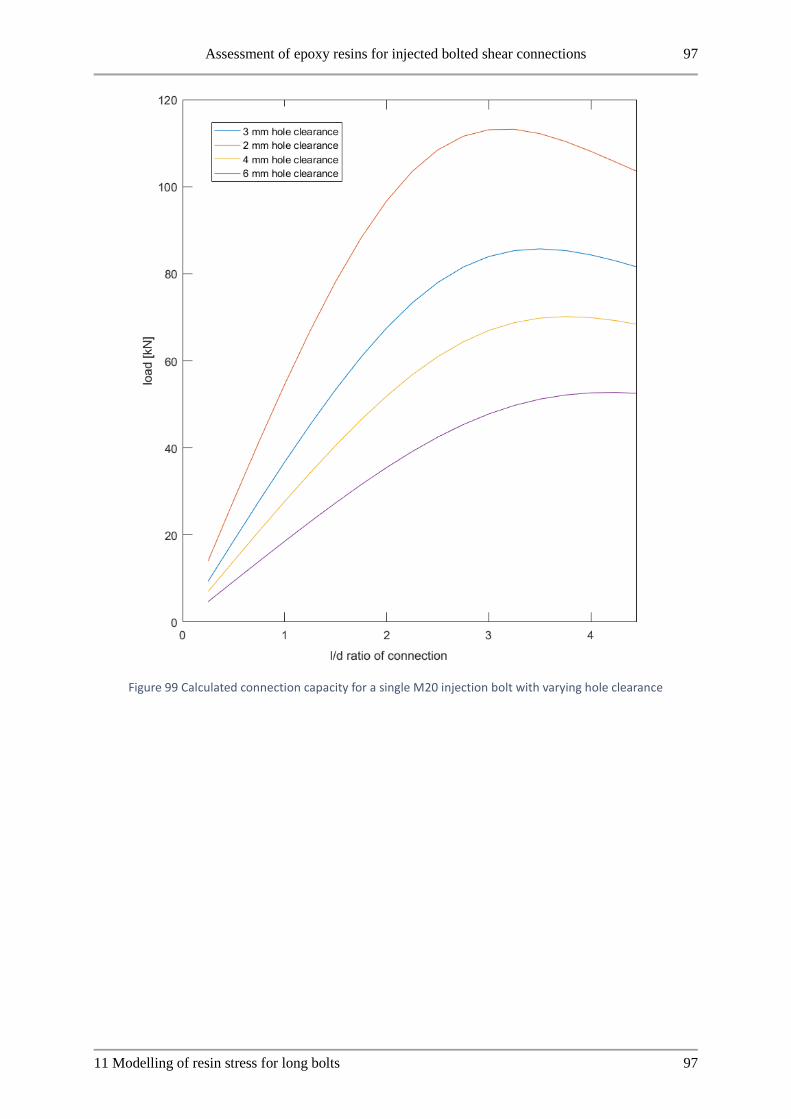
Assessment of epoxy resins for injected bolted shear connections 97
11 Modelling of resin stress for long bolts 97
Figure 99 Calculated connection capacity for a single M20 injection bolt with varying hole clearance

98 Assessment of epoxy resins for injected bolted shear connections
98 11 Modelling of resin stress for long bolts

Assessment of epoxy resins for injected bolted shear connections 99
12 Discussion 99
12 Discussion
12.1 Linking resin material properties to performance From the results in this research no clear relation could be drawn between the supplied mechanical
properties of the resin and the performance of injection bolts. The compression of resin when confined,
as illustrated in the State of the Art in Figure 12, could provide a better link between the resins
mechanical properties and the performance in this application. Due to time and budget constraints testing
of the confined compressive values of resin was not performed in this research. A design for a setup to
perform such testing on specimens fabricated with the same procedure as injection bolts is supplied in
the appendix of this research.
12.2 Injection procedure and occurrence of air inclusions The washers used in this experimental program were according to the specifications of EN 1090-2. The
positioning of the washer influenced the injection procedure for Sika Sikadur 30. From other research
the washer design is optimized for injection. This washer design is a possible cause for the feasibility of
Sikadur 30 and for the spread observed by workers for the required injection pressure during assembly.
The injection procedure and testing was explicitly chosen to follow the research base on injection bolts
performed thus far. The injection was done in this research using a hand driven injection gun so the
pressure applied during injection is not controlled accurately. From the visual inspection method
executed in this research, air inclusions were observed in the resin layer for most specimens. This is not
reported in other research using Perspex mockups as an inspection method. From a CT scan of an
injection bolt also air inclusions are identified in the resin layer.
The air inclusions were observed across all different resin products used in this research except for Sika
Injection 451 which was not applied successfully. This includes the currently applied resin RenGel
SW404/HY2404. It is unknown whether the occurrence of air inclusions in this research is caused by
the injection procedure applied or that these air inclusions have simply not been detected with the
Perspex injection samples used for visual inspection in other research.
12.3 Scatter in the experimental results From this research a significant scatter in the results was obtained. During the research the influence of
friction was identified as a possible cause for this scatter. This influence was decreased through specific
testing and a subsequent adaptation of the assembly procedure. Despite the adaptations to decrease
friction influence on the results a large scatter in results, especially for Edilon Dex R2K resin, remained.
The reason for this scatter is not known but possible causes have been identified.
One of the main aspects identified as a cause of possible scatter is the injection procedure. The specific
aspects are the positioning of the washer at the bolt head side during injection, the occurrence of voids
in the resin layer and the applied pressure with the hand-driven injection gun.
Furthermore, the mixing of resin components is identified as a possible cause for scatter. Due to the
small volumes applied in injection bolts inhomogeneities in the mixing of the two components could
influence the found results. For Edilon Dex R2K specifically, the mixing takes place in the mixing
nozzle supplied by the manufacturer. This mixing of small resin volumes in the mixing nozzle could be
a cause of scatter in the results.
To determine the resistance values of the tested resins in this research accurately, a larger set of tests
must be performed, to gain better insight in the scatter and characteristic values that can be taken into
account.

100 Assessment of epoxy resins for injected bolted shear connections
100 12 Discussion
12.4 Analytical modelling The analytical model developed and presented in this report is intended to investigate the stress peaks
that occur in the resin layer because of bolt bending in an IBC. As discussed this model shows good
agreement with the numerical model developed by Nijgh on IBC concerning the bolt deformation in the
connection. The stress in the resin layer that is calculated from the analytical model shows worse
agreement with numerical results. Issues were seen in this modelling approach with resin stress initially
dropping below zero which had to be corrected. Also, the stress peak being constant in the model results
show that this model is not accurately representing the real connection behavior.
The analytical model does not take local deformation of the plates into account. The deformations in the
resin layer are very small. The deformation of the plate could be a reason for the model behavior not
following the FEM and experimental results. Furthermore, the occurrence of voids means the resin
spring stiffness varies locally, this is not taken into account in the analytical model either.
12.5 Limitations of research One of the research questions in this study is the application of alternative resin products for injection
bolts. The choice of resins which were selected for use in this research was based on limited research.
The resin products that were considered for the selection procedure were two-component epoxy resins.
The choice of Sikadur 30 resin was supported by current research [28]. RenGel SW404/HY2404 resin
was tested as a baseline product proven in previous research and successful practical applications. The
remaining resin products were selected based on the product data sheets supplied by the manufacturers
and through direct communication with the suppliers to determine possible alternatives. The selection
of these products was not supported by other research. Furthermore, in the selection procedure of the
resins in this research, the author was not aware of the research and application of Sika AnchorFix and
Sikadur 33 resins for injection bolts as reported on by Gresnigt. [31]
The testing procedure chosen for this research has been based on the guidelines of EN 1090. This aligns
with the previous research done on this topic explained in the State of the art. The tests performed were
short duration tests with static load procedures. This means the conclusions of this research cannot be
extended to other load cases in which further research is required. The time-dependent creep of the resin
layer was briefly investigated in additional loading on test specimens in this research, but the duration
of this test was too short to draw meaningful conclusions on the long duration behavior of tested resins.
Tests on the creep behavior of connections with varying bolt hole sizes is ongoing at TU Delft using
RenGel and Dex R2K resins.
The washer design was not varied in this research. The product Sika Sikadur 30 showed good results in
IBC from other research using optimized washer designs [28]. This research did not consider alternative
washers for resin products.
The variation in the geometry of the connection in this research has been limited to the L/D ratio of the
connection. For this ratio only the plate package thickness 𝑙 has been varied. The effect of bolt size has
not been studied in this research. Other variations in the connection geometry such as the ratio between
the center and cover plate thickness 𝑡1 𝑡2⁄ and hole clearance have not been considered in this
experimental research. The hole clearance was analyzed as a parameter in the analytical model.
Experimental research into the effect of bolt size is ongoing at TU Delft currently. The effect of the size
of the hole clearance has been studied recently in TU Delft research performed by Nijgh [32].
Finally, as mentioned in the State of the art injection bolts may be applied in combination with a preload.
This combination of preload and injection for bolted connections was not considered in this research
although research in this combination is ongoing at TU Delft as well.

Assessment of epoxy resins for injected bolted shear connections 101
12 Discussion 101
In this research, the effect of the curing temperature on the resin bearing resistance of injection bolts is
tested. From the State of the art the glass transition temperature of the resin is identified as an important
material property for the strength and stiffness of resin products. In this research, no testing has been
performed at elevated temperatures for alternative resins to investigate this material parameter. The
currently applied resin RenGel SW404/HY2404 has been tested at high temperatures in previous
research and showed good performance [9] .

102 Assessment of epoxy resins for injected bolted shear connections
102 12 Discussion

Assessment of epoxy resins for injected bolted shear connections 103
13 Conclusions and recommendations 103
13 Conclusions and recommendations
13.1 Conclusions In current practice RenGel SW404/HY2404 is the resin of choice for injection bolts. In this research
Edilon Dex G 20 and Edilon Dex R2K were injected successfully. Sika Injection 451 resin had a too
low viscosity for injection, causing it to run in between the plate surfaces of the connection. Sika Sikadur
30 had a too high viscosity leading to issues with injection around the bolt head washer. In all resin
products air inclusions were observed after disassembly of test specimens.
From the review of properties in this research the viscosity of the resin mixture, pot life, glass transition
temperature and curing shrinkage are found to be the most important properties of resins for IBC
application. The viscosity of feasible products ranged from 11.000 to 55.00-80.000 𝑚𝑃𝑎 ⋅ 𝑠. The
viscosity of Sika Injection 451 (100 𝑚𝑃𝑎 ⋅ 𝑠) was far too low. Sika Sikadur 30 is a paste and not a liquid
so no exact viscosity can be given. The pot life and glass transition temperature of a product should be
as high as possible. Curing shrinkage should be minimized for this application. Edilon Dex R2K negated
pot life considerations, the resin was mixed in the nozzle during injection itself. This simplifies the
procedure.
From testing double lap shear connections in this research the characteristic value of Edilon Dex R2K
bearing stress in short term loading is found to be 156 𝑀𝑃𝑎 when cured at 16 degrees. The spread of
this product was large.
In short duration creep tests the deformation of Edilon Dex G 20 was 3.5 times larger than the currently
applied product RenGel SW404/HY2404. Dex R2K had 18% higher creep deformation than RenGel.
Edilon Dex G 20 was discarded as an alternative, due to this creep behavior.
When overloaded, connections with injection bolts showed near linear behavior up to 0.6 mm
deformation. Four times the short duration deformation limit from EN 1090. The curing temperature had
no influence, in a practical range of 8 to 24 degrees Celsius, for the currently applied product RenGel
SW404/HY2404. Edilon Dex R2K did show a dependency on the curing temperature in this range.
The mechanical properties of the resins tested in this research, as they are supplied by the manufacturers
in their respective Product data sheets, did not show a clear correlation with their performance as an
injection material for injected bolts.
The influence of bolt length on the resistance of an injection bolt connection is investigated in this
research. Modeling the resin stress occurring for these connections was done using an analytical 1D
approach. The model can be calibrated for different resins using the Young’s modulus. The validity of
the model ended at an L/D ratio of 4 or higher [32].
The model showed a peak resistance at an L/D ratio of 3 and decreasing for higher values. This peak
resistance coincides with the maximum effective length of L/D ratio 3 specified in EN 1993-1-8.
Experimental verification using RenGel SW404/HY2404 showed no decrease in resistance for L/D
values between 3 and 4. One series even showed an increase in resistance between L/D 3 and 4.

104 Assessment of epoxy resins for injected bolted shear connections
104 13 Conclusions and recommendations
13.2 Recommendations • Material properties of resin
o Compressibility of resin as a predictor for performance
o More well-defined range of applicable viscosities
• Optimized washer design for injection
o Recheck of Sikadur 30
• Optimize injection process
o Applied pressure
o Vacuum assistance injection procedure
• Modelling
o Resin flow model from RTM to adapt for injection bolts
o Extensive FEA to determine resin stress occurring in the layer
o Improve analytical model to take plate deformation into account
• Different load cases
o Long duration tests
o Elevated temperature
• Bolt size effect on L/D ratio
• Behavior in repeated loading
o Plasticity of resin layer
• Investigate the occurrence of voids in resin layer
o CT-scan method

Assessment of epoxy resins for injected bolted shear connections 105
14 Bibliography 105
14 Bibliography [1] viba, "Epoxy gelcoat," Viba, [Online]. Available: https://www.viba.nl/nl/catalog/tooling-
composites/gelcoats/epoxy-gelcoat/epoxy-gelcoat/epoxy-gelcoat/groups/g+c+p+t+a+view.
[Accessed 2016].
[2] SCIA, "rigid connection steel structure example," [Online]. Available:
http://resources.scia.net/en/factsheets/steel/images/steeldesigner_connectionsframe-
rigid/cimg1501.jpg. [Accessed 2016].
[3] AISC, "slip-critical connections," [Online]. Available:
https://www.aisc.org/DynamicTaxonomyFAQs.aspx?id=1766. [Accessed 2016].
[4] L. Bouwman, "Voorlopig overzicht van een onderzoek naar de invloed van het opvullen met
epoxy-hars van de ruimte tussen boutsteel en gatwand bij verbindingen met diverse deklagen,"
TU Delft, Stevin Report 6-70-7, Delft, 1970.
[5] ECCS, "European Recommendations for Bolted Connections with Injection Bolts," ECCS
Publication No. 79, Brussels, 1994.
[6] J. Stark and A. Gresnigt, "Design of bolted connections with Injection Bolts," in Connections in
Steel Structures III, Behaviour, Strength and Design, Proceedings of the Third International
Workshop, pages 77-87. Pergamon.
[7] Avalon Consultancy services, "The use of composites in aerospace: Past, present and future
challenges," 2016. [Online]. Available: https://avaloncsl.files.wordpress.com/2013/01/avalon-
the-use-of-composites-in-aerospace-v2.pdf. [Accessed 13 02 2017].
[8] European Committee for Standardization, "NEN-EN 1090-2: Execution of Steel Structures and
Aluminium Structures - Part 2: Technical Requirements for Steel Structures," Nederlands
Normalisatie Instituut, Delft, 2011.
[9] A. Gresnigt, G. Sedlacek and M. Paschen, "Injection bolts to repair old bridges," proceedings of
the fourth international workshop on connections in steel structures, pp. 349-360, 1996.
[10] J. Kortis, "The Numerical Solution for the Bolted connection with the Low-Quality Injection
Bolts," in Proceedings of the 9th International Conference on New Trends in Statics and
Dynamics of Buildings, Bratislava, 2011.
[11] H. van Lint, J. van Wolfswinkel and A. Gresnigt, "Besparen op Injectiebouten," Bouwen met
Staal, pp. 44-48, April 2012.
[12] A. Gresnigt and D. Beg, "Design Bearing Stresses for Injection Bolts with Short and Long
duration High Loads," Research and Applications in Structural Engineering, Mechanics and
Computation, vol. 2013, pp. 471-472, 2013.
[13] L. Bouman, "De invloed van de dikteverhoudingen van hoofd- en stuikplaten op de toelaatbare
stuikspanning bij verbindingen met injectie-bouten," TU Delft, Stevin Report 6-74-11, 1974.
[14] A. van der Vegt, From Polymers to Plastics, Delft: DUP Blue Print, 2002.
[15] P. Painter and M. Coleman, Essentials of Polymer Science and Engineering, Lancaster,
Pennsylvania: DEStech Publications Inc., 2009.

106 Assessment of epoxy resins for injected bolted shear connections
106 14 Bibliography
[16] wikimedia commons, "epoxide group chemical structure," [Online]. Available:
https://en.wikipedia.org/wiki/File:Epoxide_generic.png. [Accessed 2017].
[17] wikimedia commons, "copolymerized epoxy resin," [Online]. Available:
https://commons.wikimedia.org/wiki/File:VernetzteEpoxidharze.svg. [Accessed 2017].
[18] Epotek, "Pot Life, Working Life and Gel Time of Epoxies," 2014. [Online]. Available:
http://www.epotek.com/site/files/Techtips/pdfs/techtips_26_7.pdf. [Accessed 2016].
[19] M. Barnard, "controlling Exotherm," Epoxyworks, [Online]. Available:
http://epoxyworks.com/index.php/controlling-exotherm/. [Accessed 2016].
[20] R. Carbas, E. Marques, A. Lopes and L. da Silva, "Effect of Cure Temperature on the glass
transition temperature of an epoxy adhesive," in 15th international conference on experimental
mechanics, Porto, 2012.
[21] Y. Eom, L. Boogh, V. Michaud, P. Sunderland and J. Manson, "Dynamics of void formation
upon curing of epoxy resin," in Proceedings of ICCM conference 12 (International committee on
Composite Materials), Paris, France, 1999.
[22] X. Liu and F. Chen, "A Review of Void Formation and its Effects on the Mechanical Performance
of Carbon Fiber Reinforced Plastic," Engineering Transactions, no. 64, pp. 33-51, 2016.
[23] Y. Chekanov, V. Korotkov, B. Rozenberg, E. Dhzavadyan and L. Bogdonova, "Cure shrinkage
defects in epoxy resins," Polymer, vol. 10, no. 36, pp. 2013-2017, 1995.
[24] Inter-Composite, "Gelcoat Resin: Araldite SW404 Resin with HY2404 Hardener," [Online].
Available: http://inter-composite.com/wp-content/uploads/2012/12/Araldite-SW-404-a-HY-
2404.pdf. [Accessed 2016].
[25] D. de Freitas, M. de Araujo and J. Cerri, "Propriedades Mecanicas de Molde de Composito
Multicamadas para Colagem Sob Pressao Pecas Ceramica," CBECIMAT, 2012.
[26] International organization for standardization, NEN-EN-ISO 604 Plastics - Determination of
compressive properties, Delft: Nederlands Normalisatie Instituut, 2003.
[27] K. Ravi-Chandar and Z. Ma, "Inelastic Deformations in Polymers under Multiaxial
Compression," Mechanics of Time-dependent Materials, vol. 2, no. 16, pp. 333-357, 2000.
[28] B. Zafari, J. Qureshi, J. Mottram and R. Rusev, "Static and Fatigue Performance of Resin injected
bolts for a Slip and fatigue resistant connection in FRP bridge engineering," Structures, no. 7, pp.
71-84, 2016.
[29] J. Qureshi and J. Mottram, "Resin Injected Bolted Connections: A Step Towards Achieving Slip-
Resistant Joints in FRP Bridge Engineering," in FRP Bridges 2012 - Netcomposites, London,
2012.
[30] L. Bouwman and H. Kluwen, "De invloed van water op de mechanische eigenschappen van 3
verschillende hars/harder systemen," TU Delft, Stevin report 6-73-2, Delft, 1973.
[31] A. Gresnigt and P. de Vries, "Injection bolts update on Research and Applications," in AISC-
ECCS workshop, 2016.

Assessment of epoxy resins for injected bolted shear connections 107
14 Bibliography 107
[32] M. Nijgh, New materials for Injected Bolted Connections, Delft: TU Delft, 2017.
[33] L. Bouwman, "Het spuiten van kunsthars, in de ruimte tussen boutsteel en gatwand, met behulp
van handspuiten en luchtdrukspuiten," TU Delft, stevin report 6-70-9, Delft, 1970.
[34] X. Song, Vacuum Assisted Resin Transfer Molding (VARTM): Model Development and
Verification, Blacksburg, Virginia: Virginia Polytechnic Institute and State University, 2003.
[35] L. Bouwman, "De invloed van opwarmen op de uithardingssnelheid van injectiehars bij
injectiebouten," TU Delft, Stevin Report 6-82-8, Delft, 1982.
[36] H. Kluwen, "Onderzoek aan verbindingen met voorspanbouten en voorspaninjectiebouten me
behandelde contactvlakken onder duurbelasting t.b.v. Rijkswaterstaat (Project Oosterschelde),"
TU Delft, Stevin Report 6-82-12, Delft, 1982.
[37] H. Kluwen and T. Gruintjes, "Bepaling van wrijvingsfactoren van verbindingen met
voorspanbouten en voorspan-injectiebouten. De contactvlakken zijn thermisch verzinkt en/of
voorzien van verfsystemen," TU Delft, Stevin Report 6-83-19, Delft, 1983.
[38] C. den Boer and L. Bouwman, "Vermoeiingsonderzoek welijzeren proefstukken met injectie-
voorspanbouten, voor de spoorbrug te culemborg," TU Delft, Stevin report 6-72-12, Delft, 1972.
[39] J. Correia, A. de Jesus, C. Rebelo and L. da Silva, "Fatigue Behaviour of Single and Double Shear
connections with Resin-Injected Preloaded Bolts," in 19th congress of IABSE Stockholm 2016,
Stockholm, 2016.
[40] T. Rugelj and D. Beg, Uporaba injektiranih vijakov v jeklenih, Ljubljana: Univerza v Ljubljani,
2008, pp. 171-178.
[41] European Committee for Standardization, "NEN-EN 1993-1-8: Design of Steel Structures Part
1-8: Design of Joints," Nederlands Normalisatie Instituut, Delft, 2011.
[42] A. de Jesus, J. da Silva, M. Figueiredo, A. Ribeiro, A. Fernandes, J. Correia, A. da Silva and J.
Maeiro, "Fatigue behaviour of Resin-injected Bolts: An Experimental Approach," in Iberian
Conference on Fracture and Structural Integrity, 2010.
[43] H. Smits and L. Bouman, "Investigation to the application of Seperating Liquids for injected
bolted connections," TU Delft, Stevin Report 6-72-14, Delft, 1972.
[44] I. Ward and J. Sweeney, Mechanical Properties of Solid Polymers, 3 ed., chichester, West Sussex:
John Wiley & Sons, Ltd., 2013.
[45] J. Cowie and V. Arrighi, Polymers: Chemistry and Physics of Modern Materials, 2nd Edition,
CRC Press, 2007.
[46] E. O'Brien, "Durability of Adhesive Joints Subjected to Environmental Stress," Virginia
Polytechnic Institute and State University, Blacksburg, Virginia, 2003.
[47] G. Viana, M. Costa, M. Banea and L. da Silva, "A review on the temperature and moisture
degradation of adhesive joints," Journal of Materials: Design and Applications, pp. 1-14, 2016.
[48] European Committee for Standardization, "NEN-EN 14399: High Strength Structural Bolting
Assemblies for Preloading," Nederlands Normalisatie Instituut, Delft, 2015.

108 Assessment of epoxy resins for injected bolted shear connections
108 14 Bibliography
[49] European Committee for Standardization, "NEN-EN 15048: Non-preloaded structural bolting
assemblies," Nederlands Normalisatie Instituut, Delft, 2016.
[50] European Committee for Standardization, "NEN-EN 1993-1-9: Design of steel structures - Part
1-9: Fatigue," Nederlands Normalisatie Instituut, Delft, 2012.
[51] AISC, "Steelwise - When and when not to specify slip-critical connections," 1 2016. [Online].
Available: https://www.aisc.org/globalassets/modern-steel/archives/2016/01/steelwise.pdf.
[Accessed 2017].
[52] Sika Ltd., "Sikadur-30 Lijmmortel voor verlijming van wapening," [Online]. Available:
http://nld.sika.com/dms/getdocument.get/5e862000-27cb-3c49-980f-
c3740a010d1a/tds_sikadur30_nl.pdf. [Accessed 2016].
[53] Sika Ltd., "Sika Injection-451 Laag viskeuze epoy injectie hars," 8 12 2010. [Online]. Available:
http://nld.sika.com/dms/getdocument.get/454fb55a-09ba-3b49-a079-
65edd3985696/tds_sikainjection451_nl.pdf. [Accessed 2016].
[54] edilon)(sedra, "productinformatieblad EDILON Dex-R 2K," 1 5 2012. [Online]. Available:
http://edilondex.nl/file/mryuj57niinqqoaz/PDS_Dex-R+2K_070209+rev+09_NL.pdf.
[Accessed 2016].
[55] edilon)(sedra, "Productinformatieblad edilon)(sedra Dex-G type 20/40/80," 12 3 2014. [Online].
Available: http://edilondex.nl/file/5e60q2fmeavvgi8y/PDS_Dex-G+20-40-
80_070504+rev+09_NL.pdf. [Accessed 2016].
[56] P. de Vries, "SIROCO - Bouwen met Staal," 20 5 2016. [Online]. Available:
http://www.bouwenmetstaal.nl/uploads/evenementen/techniekdag2016/05_Slip_resistant_conne
ctions_preload_in_bolts_pdv_May_2016.pdf. [Accessed 2017].
[57] edilon)(sedra, "gebruikersinstructieblad Edilon Dex-R 2K," 8 11 2010. [Online]. Available:
http://edilondex.nl/file/3jf9f2m73sbm9hd6/USER_Dex-
R_2K_%28NL%29_070404_rev_03%5B1%5D.pdf. [Accessed 2016].
[58] J. Li, unpublished work, Delft: TU Delft, 2017.
[59] W. Gard, unpublished work, Delft: TU Delft, 2016.
[60] S. Timoshenko, "On the correction for shear of the differential equation for transverse vibrations
of prismatic bars," Philosophical Magazine, no. 41, pp. 744-746, 1921.
[61] S. Timoshenko, "On the transverse vibrations of bars of uniform cross-section," Philosophical
Magazine, no. 43, pp. 125-131, 1922.
[62] A. Simone, An Introduction to the Analysis of Slender Structures, Delft: TU Delft, 2011.
[63] Mathworks, "Solve boundary value problems for ordinary differential equations," Mathworks
benelux, [Online]. Available: https://nl.mathworks.com/help/matlab/ref/bvp4c.html. [Accessed
25 10 2016].
[64] Mathworks, "Tutorial on solving bvps with BVP4C," [Online]. Available:
https://nl.mathworks.com/matlabcentral/mlc-
downloads/downloads/submissions/3819/versions/6/download/zip. [Accessed 02 11 2016].

Assessment of epoxy resins for injected bolted shear connections 109
14 Bibliography 109
[65] J. Schultz, Lateral-Mode Vibration of Microcantilever-based Sensors in Viscous Fluids using
timoshenko beam theory, Milwaukee, wisconsin: Marquette university, 2012.
[66] Mathworks, "Solve boundary value problems for ordinary differential equations - matlab bvp4c
- mathworks benelux," [Online]. Available:
https://nl.mathworks.com/help/matlab/ref/bvp4c.html. [Accessed 25 10 2016].
[67] Mathworks, "Tutorial on solving bvps with BVP4C," [Online]. Available:
https://nl.mathworks.com/matlabcentral/mlc-
downloads/downloads/submissions/3819/versions/6/download/zip. [Accessed 02 11 2016].
[68] B. Carvalho, Modelacao por elementos finitos do comportamento de ligacoes, Villa Real:
Universidade de Tras-os-Montes e Alto, 2013.
[69] S. Kajorncheappunngam, The Effects of Environmental Ageing on the Durability of Glass/Epoxy
Composites, Ann Arbor: Howeel Information and Learning Company, 1999.
[70] C. Daniels, Polymers: Structure and Properties, Lancaster: Technomic Publishing Company Inc.,
1999.
[71] M. Miravalles and I. Dharmawan, The Creep Behaviour of Adhesives, Goteborg: Chalmers
University of Technology, 2007.

110 Assessment of epoxy resins for injected bolted shear connections
110 14 Bibliography

Assessment of epoxy resins for injected bolted shear connections I
I
15 Appendix A: Solution of Analytical Timoshenko model using BVP4C
MATLAB routine
15.1.1 Deriving the governing equations of analytical model To solve the schematized analytical model from Figure 100 the Timoshenko beam theory is applied [60]
[61]. To take the foot displacement of the distributed springs into account the governing equations will
be derived. This is done according to the methods explained in chapter four of the CIE4190 course reader
on slender structures [62].
Figure 100 overview of analytical model schematization
Kinematic equations
First, the derivation is started by deriving the kinematic equations following the starting assumptions for
the Timoshenko theory. That is plane sections remain plane but contrary to the Euler-Bernoulli theory
they do not remain perpendicular to the neutral axis [62]. The assumptions for positive directions are
shown in Figure 101.
𝑆𝑥(𝑥, 𝑦) = −𝜙(𝑥) ⋅ 𝑦
𝑆𝑦(𝑥, 𝑦) = 𝑣(𝑥)
𝜖𝑥𝑥 =𝑑𝑆𝑥
𝑑𝑥= −𝑦 ⋅
𝑑𝜙
𝑑𝑥
𝛾𝑥𝑦 =𝑑𝑆𝑥
𝑑𝑦+
𝑑𝑆𝑦
𝑑𝑥= −𝜙 +
𝑑𝑣
𝑑𝑥
Figure 101 Assumed directions for derivation of kinematic equations [62]

II Assessment of epoxy resins for injected bolted shear connections
II
tan(𝜃) =𝑑𝑣
𝑑𝑥
𝑅𝑑𝜃 = 𝑑𝑠
𝑑𝑠
𝑑𝜃= 𝑅
1
𝑅= 𝜅 =
𝑑𝜃
𝑑𝑠
We assume that the rotations of the beam stay small. Therefore, the following approximation holds:
sin(𝜃) ≈ tan (𝜃) ≈ 𝜃
𝑑𝑠 ≈ 𝑑𝑥
And thus:
𝜅 =𝑑𝜃
𝑑𝑥
𝜃 =𝑑𝑣
𝑑𝑥
𝜅 =𝑑2𝑣
𝑑𝑥2
This solves the kinematic equations for the Timoshenko theory.
Equilibrium equations
What follows is the equations that relate to the force equilibrium of the model. The positive force
directions are indicated in Figure 102. This figure shows an infinitesimal segment of the beam for which
the equilibrium conditions must hold. For this model second order terms of derivatives are neglected
[62]. The force related to the distributed springs of Figure 102 has a term with 𝑣 and 𝑤. These are the
displacements of the beam itself and the foot of the spring layer respectively. The positive conventions
of this is shown in Figure 103.
Figure 102 positive force directions equilibrium equations

Assessment of epoxy resins for injected bolted shear connections III
III
Figure 103 positive displacements distributed springs
Now we can derive the equilibrium conditions of the model:
∑𝑀 = 0
∑𝑀 = 𝑀 = 𝑑𝑀 − 𝑀 − 𝑉 ⋅ 𝑑𝑥 = 0
∑𝑀 = 𝑑𝑀 − 𝑉 ⋅ 𝑑𝑥 = 0
𝑑𝑀 = 𝑉 ⋅ 𝑑𝑥
𝑑𝑀
𝑑𝑥= 𝑉
∑𝐹𝑦 = 0
∑𝐹𝑦 = 𝑉 + 𝑑𝑉 − 𝑉 + (𝑞 − 𝑘 ⋅ (𝑣 − 𝑤)) ⋅ 𝑑𝑥 = 0
𝑑𝑉 + 𝑞𝑑𝑥 − 𝑘𝑑𝑥 ⋅ (𝑣 − 𝑤) = 0
𝑑𝑉
𝑑𝑥+ 𝑞 − 𝑘 ⋅ (𝑣 − 𝑤) = 0
𝑑𝑉
𝑑𝑥= −𝑞 + 𝑘 ⋅ (𝑣 − 𝑤)
Constitutive equations
Last to complete the derivations of the governing equations is the constitutive equations. These relate
the displacements and deformations to the stresses that occur in the material. For this reference is made
to [62]. Hereby 𝐸 is the young’s modulus of the material, 𝐺 the shear modulus, 𝐴𝑠 the effective area in
shear and 𝐼 the second moment of inertia of the cross-section.
𝑑𝑀 = 𝜎𝑥 ⋅ 𝑦 ⋅ 𝑑𝐴
∫ 𝑑𝑀 = 𝑀 = ∫ 𝜎𝑥 ⋅ 𝑦 ⋅ 𝑑𝐴
∫ 𝜎𝑥 ⋅ 𝑦 ⋅ 𝑑𝐴 = ∫ 𝐸 ⋅ 𝜖𝑥𝑥 ⋅ 𝑦 ⋅ 𝑑𝐴
∫ 𝐸 ⋅ 𝜖𝑥𝑥 ⋅ 𝑦 ⋅ 𝑑𝐴 = −∫ 𝐸 ⋅ 𝑦 ⋅𝑑𝜙
𝑑𝑥⋅ 𝑦 ⋅ 𝑑𝐴

IV Assessment of epoxy resins for injected bolted shear connections
IV
−∫ 𝐸 ⋅ 𝑦 ⋅𝑑𝜙
𝑑𝑥⋅ 𝑦 ⋅ 𝑑𝐴 = −𝐸 ⋅
𝑑𝜙
𝑑𝑥⋅ ∫ 𝑦2 ⋅ 𝑑𝐴 = −𝐸 ⋅ 𝐼 ⋅
𝑑𝜙
𝑑𝑥
𝑀 = −𝐸𝐼 ⋅𝑑𝜙
𝑑𝑥
𝑑𝑀
𝑑𝑥= −𝐸𝐼 ⋅
𝑑2𝜙
𝑑𝑥2
Again, making use of the assumption of small rotations we can find the following:
𝛾 = tan𝑑𝑣
𝑑𝑥≈
𝑑𝑣
𝑑𝑥
𝜏 = 𝐺 ⋅ 𝛾
𝜏 =𝑉
𝐴𝑠
𝛾 =𝑉
𝐺 ⋅ 𝐴𝑠
𝛾 = −𝜙 +𝑑𝑣
𝑑𝑥
𝑉 = 𝐺𝐴𝑠(𝑑𝑣
𝑑𝑥− 𝜙)
Combining all the above equations we can find the governing equations for the problem:
𝑑𝑀
𝑑𝑥= 𝑉 = −𝐸𝐼 ⋅
𝑑2𝜙
𝑑𝑥2
−𝐸𝐼 ⋅𝑑2𝜙
𝑑𝑥2= 𝐺𝐴𝑠 ⋅ (
𝑑𝑣
𝑑𝑥− 𝜙)
𝑉 = 𝐺𝐴𝑠(𝑑𝑣
𝑑𝑥− 𝜙)
𝑑𝑉
𝑑𝑥= 𝐺𝐴𝑠 ⋅ (
𝑑2𝑣
𝑑𝑥2−
𝑑𝜙
𝑑𝑥) = −𝑞 + 𝑘 ⋅ (𝑣 − 𝑤)
So, to summarize we find two second order dependent differential equations which govern the deflection
of the bolt shank loaded by a set of distributed springs which represent the resin layer of the injection
bolt. Furthermore the 𝑞 term represents an external distributed load but this is not used further in the
modelling but was left included for completeness.
𝐺𝐴𝑠 ⋅ (𝑑2𝑣
𝑑𝑥2−
𝑑𝜙
𝑑𝑥) = −𝑞 + 𝑘 ⋅ (𝑣 − 𝑤)
−𝐸𝐼 ⋅𝑑2𝜙
𝑑𝑥2= 𝐺𝐴𝑠 ⋅ (
𝑑𝑣
𝑑𝑥− 𝜙)
The equations above govern the deflection of the analytical model. To formulate a solution to these
equations the boundary conditions must be considered. Due to the discontinuities in the loading that
occur at the interface between center and cover plate the solution must be derived in three solution fields.
To take this into account interface conditions between the different solution fields are needed. The
boundary conditions and interface conditions are summarized below in Table 30. An overview of the
solution fields is also given in Figure 104.

Assessment of epoxy resins for injected bolted shear connections V
V
Figure 104 analytical model with solution fields in yellow
Table 30 Overview of boundary conditions analytical model
Boundary conditions analytical model
Left boundary (𝒙 = 𝟎) Interface 1 (𝑥 = 𝑡2) Interface 2 (𝑥 = 𝑡1 + 𝑡2) Right boundary
( 𝑥 = 𝑡1 + 2 ⋅ 𝑡2)
𝑽 = 𝟎 𝑀1 = 𝑀2 𝑀2 = 𝑀3 𝑉 = 0
𝝓 = 𝟎 𝑉1 = 𝑉2 𝑉2 = 𝑉3 𝜙 = 0
𝜙1 = 𝜙2 𝜙2 = 𝜙3
𝑣1 = 𝑣2 𝑣2 = 𝑣3
15.1.2 Solving the governing equations To solve the governing equations derived above using the boundary conditions from Table 30 MATLAB
is used. The system of differential equations is known as a boundary-value problem. To solve this the
BVP4C solver routine built into MATLAB is used. This will give a numerical approximation to the
analytical solution. To apply this solver a specific format of the differential equations and boundary
conditions must be used. Reference is made here to previous research on analytical modelling of
Timoshenko beams using the BVP4C solver as an example. [65] [63] [66]
15.1.3 Reduction of order and solution fields The BVP4C solver can only deal with first order differential equations. [66] The Timoshenko equations
consist of two coupled second order differential equations. Therefore, a reduction of order must be
applied on both main variables 𝑣 and 𝜙. For this the example supplied in Appendix A of [65] is followed.
This is shown below:
𝑓1 = 𝜙
𝑓2 =𝑑𝑓1
𝑑𝑥=
𝑑𝜙
𝑑𝑥
𝑑2𝜙
𝑑𝑥2=
𝑑𝑓2
𝑑𝑥
𝑣1 = 𝑣

VI Assessment of epoxy resins for injected bolted shear connections
VI
𝑣2 =𝑑𝑣1
𝑑𝑥=
𝑑𝑣
𝑑𝑥
𝑑2𝑣
𝑑𝑥2=
𝑑𝑣2
𝑑𝑥
Using the newly defined variables 𝑓1, 𝑓2, 𝑣1, 𝑣2 we can now write the governing equations as:
𝐸𝐼 ⋅ 𝑓2′ + 𝐺𝐴𝑠 ⋅ (𝑣2 − 𝑓1) = 0
𝑓2′ = −
𝐺𝐴𝑠
𝐸𝐼⋅ (𝑣2 − 𝑓1)
𝐺𝐴𝑠 ⋅ (𝑣2′ − 𝑓2) = −𝑞 + 𝑘 ⋅ (𝑣1 − 𝑤)
𝑣2′ =
−𝑞 + 𝑘 ⋅ (𝑣1 − 𝑤)
𝐺𝐴𝑠+ 𝑓2
In the solution script the reduced order variables are all stored in a separate solution vector 𝑦. This is
structured as follows:
𝑦 = [ 𝑓1 𝑓2 𝑣1 𝑣2 ]
As mentioned earlier the solution must be derived in three solution fields. The implementation of
splitting the three fields is shown here below in X. The que for BVP4C to know the edge of a solution
field is a repeated entry in the vector with x coordinates of the solution.
Figure 105 implementation of splitting solution field
15.1.4 Applying boundary conditions To apply the BVP4C solver the boundary conditions as determined before in Table 30 must be rewritten
in the reduced order variables and the residuals must be computed. BVP4C works by minimizing the
residuals of the solution and the boundary condition as specified by the user. First, the boundary
conditions in the reduced order variables will be derived. To indicate the different fields and order of
derivative term two subscripts are used here. The first index refers to the field of the variable. The second
index denotes the order of derivative the term represents.
The left and right boundary as applied in reduced order variables gives the following:
𝑜𝑛 𝑥 = 0
𝑉1 = 𝐺𝐴𝑠 ⋅ (𝑣1,2 − 𝑓1,1) = 0
𝜙1 = 𝑓1,1 = 0
𝑜𝑛 𝑥 = 𝑡1 + 2 ⋅ 𝑡2
𝑉3 = 𝐺𝐴𝑠 ⋅ (𝑣3,2 − 𝑓3,1) = 0
𝜙3 = 𝑓3,1 = 0
function v = xinitial
%XINITIAL makes linearly spaced 3 field mesh of the bolt
v1 = linspace(0,t2,n/3);
v2 = linspace(t2,t1+t2,n/3);
v3 = linspace(t1+t2,t1+t2+t2,n/3);
v = [v1 v2 v3];
end

Assessment of epoxy resins for injected bolted shear connections VII
VII
The interface conditions between the different fields in the reduced order variables gives the following:
𝑜𝑛 𝑥 = 𝑡2
𝑉1 = 𝑉2
𝐺𝐴𝑠 ⋅ (𝑣1,2 − 𝑓1,1) = 𝐺𝐴𝑠 ⋅ (𝑣2,2 − 𝑓2,1)
𝜙1 = 𝜙2
𝑓1,1 = 𝑓2,1
𝑀1 = 𝑀2
−𝐸𝐼 ⋅ 𝑓1,2 = −𝐸𝐼 ⋅ 𝑓2,2
𝑣1 = 𝑣2
𝑣1,1 = 𝑣2,1
In similar fashion the interface between the second and third solution field gives the following:
𝑜𝑛 𝑥 = 𝑡1 + 𝑡2
𝐺𝐴𝑠 ⋅ (𝑣2,2 − 𝑓2,1) = 𝐺𝐴𝑠 ⋅ (𝑣3,2 − 𝑓3,1)
𝑓2,1 = 𝑓3,1
−𝐸𝐼 ⋅ 𝑓2,2 = −𝐸𝐼 ⋅ 𝑓3,2
𝑣2,1 = 𝑣3,1
From the documentation of the BVP4C solver when using a multiple field approach the boundary
conditions must be stored in two separate matrices. One containing all the conditions at the left side of
each field and the second matrix with all the conditions at the right side of the fields. [66] [67] These
matrices are denoted as YL and YR in the script for this problem. Lastly the boundary conditions must
be computed as residuals, all terms are moved to one side such that the value is zero when the boundary
condition is met exactly. This is shown for one boundary condition below:
−𝐸𝐼 ⋅ 𝑓1,2 = −𝐸𝐼 ⋅ 𝑓2,2
−𝐸𝐼 ⋅ (𝑓1,2 − 𝑓2,2) = 0
This implementation of residuals and boundary condition matrices can be seen in the code snippet of
Figure 106.

VIII Assessment of epoxy resins for injected bolted shear connections
VIII
Figure 106 implementation of boundary conditions and residuals
15.1.5 Implementing numerical solver mesh size Now we can apply the BVP4C solver to find a solution to the governing equations. BVP4C finds a
numerical approximation to the analytical solution on a mesh of points along the length. Due to the
solution being sought in three fields it is necessary that the number of mesh points 𝑛 is a multiple of
three. From the documentation of BVP4C it can be found that the mesh size 𝑛 will be automatically
adjusted when the desired accuracy of the solution cannot be found. [66] This adjusted mesh size is not
necessarily a multiple of three so a manual catch is put in the script when this happens to guarantee 𝑛 is
a multiple of three. This is shown in the code snippet below in Figure 107. This implementation
guarantees the accuracy of the solution is maintained and that the solution mesh is a multiple of three so
a discrete number of points fits in each field.
function res = bc(YL,YR)
%BC Function that finds the residuals of the BCs of the bolt
res = [GAs*(YL(4,1)-YL(1,1)) %V1(0)=0 force balance on the bolt
YL(1,1) %phi1(0)=0 clamped end
YR(3,1)-YL(3,2) %w1(t2)=w2(t2) matching conditions 1,2
-EI*(YR(2,1)-YL(2,2)) %M1(t2)= M2(t2)
GAs*(YR(4,1)-YR(1,1))-GAs*(YL(4,2)-YL(1,2)) %V1(t2)=V2(t2)
YR(1,1)-YL(1,2) %phi1(t2)=phi2(t2)
YR(3,2)-YL(3,3) %w1(t2)=w2(t2) matching conditions 2,3
-EI*(YR(2,2)-YL(2,3)) %M1(t2)= M2(t2)
GAs*(YR(4,2)-YR(1,2))-GAs*(YL(4,3)-YL(1,3)) %V2(t2)=V3(t2)
YR(1,2)-YL(1,3) %phi1(t2)=phi2(t2)
GAs*(YR(4,3)-YR(1,3)) %V3(t1+2*t2)=0 force balance
YR(1,3) %phi3(t1+2*t2)=0
];
end

Assessment of epoxy resins for injected bolted shear connections IX
IX
Figure 107 Mesh size check implementation BVP4C
15.1.6 Full MATLAB implementation BVP4C solver For clarity the full script used to determine the deflections with the BVP4C solver is shown here on the
next pages:
sol = bvp4c(@ex1ode,@bc,solinit,options);
if size(sol.x,2) ~= n
disp('mesh size adjusted!');
disp('mesh size:');
disp(size(sol.x,2));
disp('n:');
disp(n);
%triple mesh size for new attempt
n = n*3;
%run solver again using the enlarged mesh
xinit = xinitial;
yinit = [0.00 0.00 0.00 0.00];
solinit = bvpinit(xinit,yinit);
options = bvpset('Stats','on','RelTol',1e-7,'NMax',n);
sol = bvp4c(@ex1ode,@bc,solinit,options);
%report wether the new solution follows n.
disp('new n:');
disp(n);
disp('mesh size new:');
disp(size(sol.x,2));
end

X Assessment of epoxy resins for injected bolted shear connections
X
function [LD,AVGstress,ConnCap, Sols] =
bolt_bending_timoshenko(max_ld,nr_steps,mesh_size)
%function to solve euler bernoulli theory bending of bolt
%close all; clear all;
EI = 1*16.449336*10^8;
q = 0;
w1 = -0.075; %mm
w2 = 0.075; %mm
Bolt_Clearance = 3; %mm
dbolt = 20;
rbolt = dbolt/2;
As = 0.9*pi*(rbolt)^2;
G = 210000/(2*(1+0.28));
GAs = G*As;
disp(GAs);
E_Resin = 7500; % N/mm^2
k_linear = (E_Resin*dbolt)/Bolt_Clearance;
k = k_linear;
%GAs = 1*10^14;
n = mesh_size; % number of points over x coordinate for
solution.
% multiple of 3.
connection_capacity = zeros(1,nr_steps);
avg_stress = zeros(1,nr_steps);
ld_matrix=zeros(1,nr_steps);
sol_comb = cell(1,nr_steps); %cell array with solution at every
iteration
sol_comb(:) = {0}; % 4 rows per step for full sol
for j = 1:nr_steps
ld_ratio=(max_ld/nr_steps)*j;
t1 = 0.5*ld_ratio*dbolt; %mm
t2 = 0.25*ld_ratio*dbolt; %mm
xinit = xinitial;
yinit = [0.00 0.00 0.00 0.00];
solinit = bvpinit(xinit,yinit);
options = bvpset('Stats','on','RelTol',1e-7,'NMax',n);
sol = bvp4c(@ex1ode,@bc,solinit,options);
if size(sol.x,2) ~= n
disp('mesh size adjusted!');
disp('mesh size:');
disp(size(sol.x,2));
disp('n:');
disp(n);
%triple mesh size for new attempt

Assessment of epoxy resins for injected bolted shear connections XI
XI
n = n*3;
%run solver again using the enlarged
mesh
xinit = xinitial;
yinit = [0.00 0.00 0.00 0.00];
solinit = bvpinit(xinit,yinit);
options =
bvpset('Stats','on','RelTol',1e-7,'NMax',n);
sol =
bvp4c(@ex1ode,@bc,solinit,options);
%report wether the new solution follows
n.
disp('new n:');
disp(n);
disp('mesh size new:');
disp(size(sol.x,2));
end
x = sol.x;
y = sol.y;
sol_comb(j) = {sol};
i=size(x,2);
y_center_plate = y(3,(i/3)+1:(2*i/3));
x_center_plate = x(1,(i/3)+1:(2*i/3));
Sigma_center =
(E_Resin/Bolt_Clearance)*(y_center_plate(1,:)-
w1).*(heaviside(y_center_plate(1,:)-w1));
sigma_avg_center = mean(Sigma_center);
avg_stress(j) = sigma_avg_center;
ld_matrix(j) = ld_ratio;
connection_capacity(j) =
sigma_avg_center*t1*dbolt*0.001;
% for ld_ratio = 4;
% % plot(x,-y(3,:));
% % hold on;
% % plot(x,-y(1,:));
% % figure;
% plot(x_center_plate,Sigma_center);
% figure;
% end

XII Assessment of epoxy resins for injected bolted shear connections
XII
end
% plot(ld_matrix,connection_capacity);
% hold on;
% plot(ld_matrix,avg_stress);
%
% disp(max(connection_capacity));
% disp(avg_stress);
LD = ld_matrix;
AVGstress = avg_stress;
ConnCap = connection_capacity;
Sols = sol_comb;
return;
% --------------------------------------------------
------------------------
function dydx = ex1ode(x,y,region)
%EX1ODE ODE function for Example 1 of the BVP
tutorial.
% The components of y correspond to the
original variables
% as y(1) = w, y(2) = phi, y(3) = kappa, y(4)
= z
% y = [ f1 f2 v1 v2] = [ phi phi' v v']
dydx = zeros(4,1);
% dydx(1) = y(2);
% dydx(2) = y(3);
% dydx(3) = y(4);
dydx(1) = y(2);
dydx(3) = y(4);
dydx(2) = -(GAs/EI)*(y(4)-y(1));
switch region
case 1 % x in [0 t2]
%dydx(4) = (-q+k*(y(3)-w2))/GAs + y(2);
dydx(4) = (((-q+(k*(y(3)-w2)))*(1-
heaviside(y(3)-w2)))/GAs)+y(2);

Assessment of epoxy resins for injected bolted shear connections XIII
XIII
case 2 % x in [t2 t1+t2]
%dydx(4) = (-q+k*(y(3)-w1))/GAs + y(2);
dydx(4) = (((-q+(k*(y(3)-
w1)))*(heaviside(y(3)-w1)))/GAs)+y(2);
case 3 % x in [t1+t2 t1+t2+t2]
%dydx(4) = (-q+k*(y(3)-w2))/GAs + y(2);
dydx(4) = (((-q+(k*(y(3)-w2)))*(1-
heaviside(y(3)-w2)))/GAs)+y(2);
otherwise
error('MATLAB:threebvp:BadRegionIndex','Incorrect region
index: %d',region);
end
end
%---------------------------------------------------
----------------------
function res = bc(YL,YR)
%BC Function that finds the residuals of the BCs
of the bolt
res = [GAs*(YL(4,1)-YL(1,1)) %V1(0)=0 force
balance on the bolt
YL(1,1) %phi1(0)=0
clamped end
YR(3,1)-YL(3,2) %w1(t2)=w2(t2) matching
conditions 1,2
-EI*(YR(2,1)-YL(2,2)) %M1(t2)= M2(t2)
GAs*(YR(4,1)-YR(1,1))-GAs*(YL(4,2)-
YL(1,2)) %V1(t2)=V2(t2)
YR(1,1)-YL(1,2) %phi1(t2)=phi2(t2)
YR(3,2)-YL(3,3) %w1(t2)=w2(t2) matching
conditions 2,3
-EI*(YR(2,2)-YL(2,3)) %M1(t2)= M2(t2)
GAs*(YR(4,2)-YR(1,2))-GAs*(YL(4,3)-
YL(1,3)) %V2(t2)=V3(t2)
YR(1,2)-YL(1,3) %phi1(t2)=phi2(t2)
GAs*(YR(4,3)-YR(1,3)) %V3(t1+2*t2)=0
force balance
YR(1,3) %phi3(t1+2*t2)=0
];
end

XIV Assessment of epoxy resins for injected bolted shear connections
XIV
%---------------------------------------------------
--------
function v = xinitial
%XINITIAL makes linearly spaced 3 field mesh of
the bolt
v1 = linspace(0,t2,n/3);
v2 = linspace(t2,t1+t2,n/3);
v3 = linspace(t1+t2,t1+t2+t2,n/3);
v = [v1 v2 v3];
end
end

Assessment of epoxy resins for injected bolted shear connections XV
XV
16 Appendix B confined volume compressive test setup design Top plate of confined volume compressive test setup design
Figure 108 Top plate of confined volume compressive test design with resin injection channels according to EN 1090

XVI Assessment of epoxy resins for injected bolted shear connections
XVI
Figure 109 Bottom plate of compressive test confined volume design

Assessment of epoxy resins for injected bolted shear connections XVII
XVII
Figure 110 Strip to clamp cylinder during curing of resin for compressive test

XVIII Assessment of epoxy resins for injected bolted shear connections
XVIII
Figure 111 Cylinder of compressive test setup with mounting points for LVDTs

Assessment of epoxy resins for injected bolted shear connections XIX
XIX
17 Appendix C: Product data sheets of used Resins
17.1 RenGel / Araldite SW404/HY2404

XX Assessment of epoxy resins for injected bolted shear connections
XX

Assessment of epoxy resins for injected bolted shear connections XXI
XXI
17.2 Sika Sikadur 30

XXII Assessment of epoxy resins for injected bolted shear connections
XXII

Assessment of epoxy resins for injected bolted shear connections XXIII
XXIII
17.3 Sika Injection 451
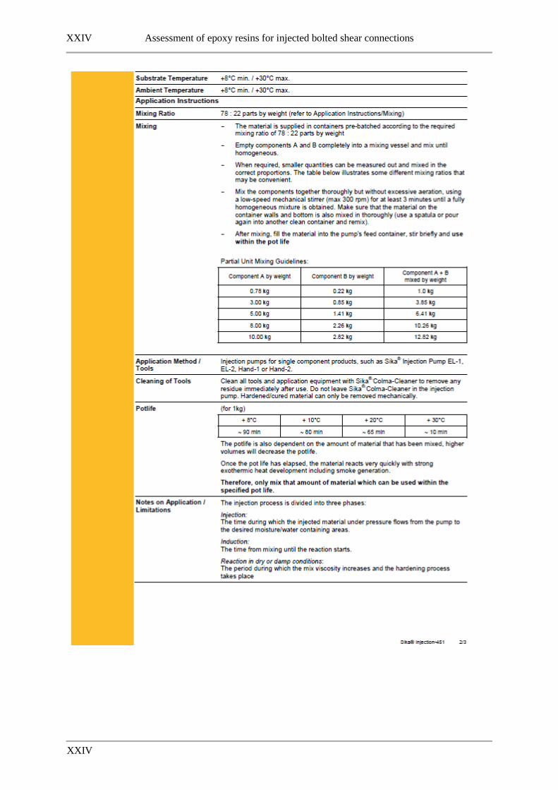
XXIV Assessment of epoxy resins for injected bolted shear connections
XXIV

Assessment of epoxy resins for injected bolted shear connections XXV
XXV

XXVI Assessment of epoxy resins for injected bolted shear connections
XXVI
17.4 Edilon Dex G 20
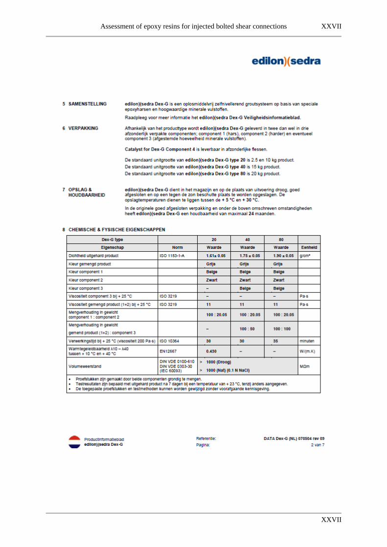
Assessment of epoxy resins for injected bolted shear connections XXVII
XXVII
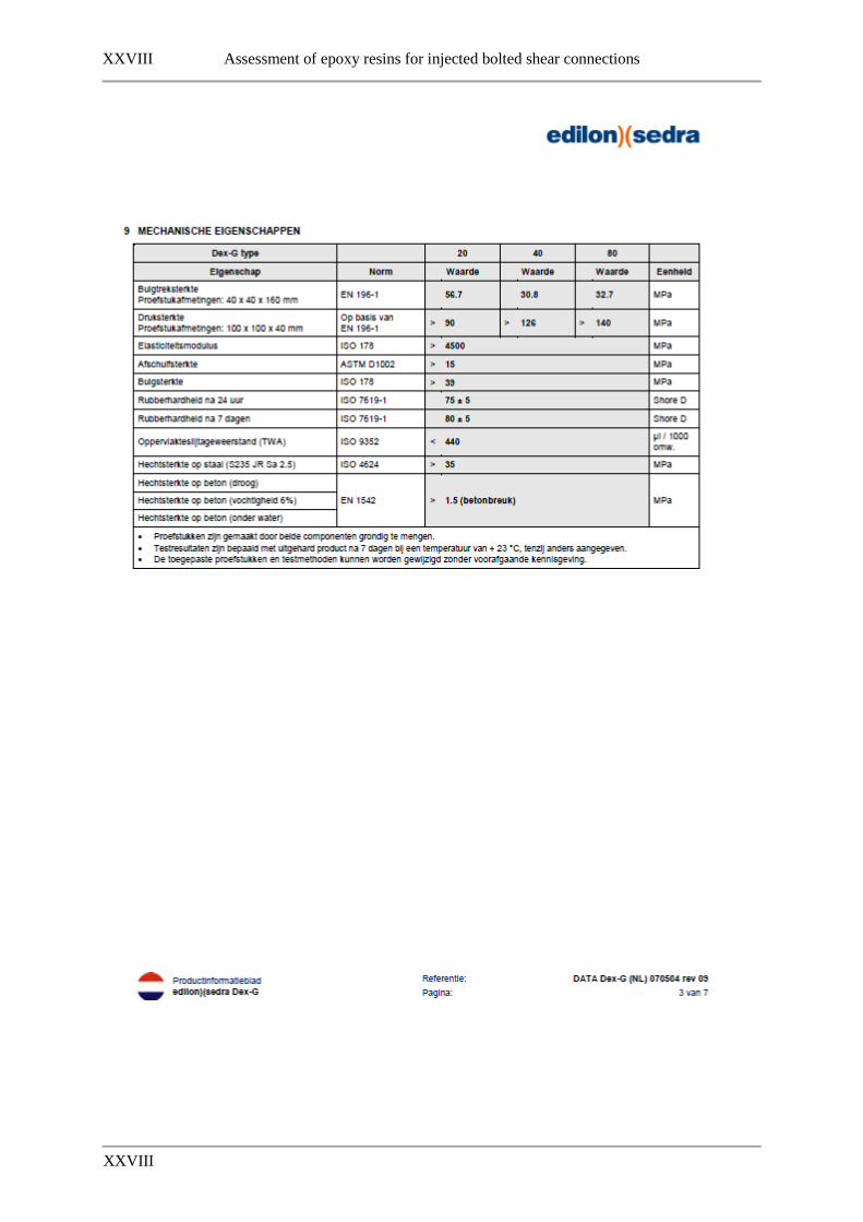
XXVIII Assessment of epoxy resins for injected bolted shear connections
XXVIII

Assessment of epoxy resins for injected bolted shear connections XXIX
XXIX

XXX Assessment of epoxy resins for injected bolted shear connections
XXX

Assessment of epoxy resins for injected bolted shear connections XXXI
XXXI

XXXII Assessment of epoxy resins for injected bolted shear connections
XXXII

Assessment of epoxy resins for injected bolted shear connections XXXIII
XXXIII
17.5 Edilon Dex R 2K

XXXIV Assessment of epoxy resins for injected bolted shear connections
XXXIV

Assessment of epoxy resins for injected bolted shear connections XXXV
XXXV

XXXVI Assessment of epoxy resins for injected bolted shear connections
XXXVI

Assessment of epoxy resins for injected bolted shear connections XXXVII
XXXVII

XXXVIII Assessment of epoxy resins for injected bolted shear connections
XXXVIII

Assessment of epoxy resins for injected bolted shear connections XXXIX
XXXIX