asset class management plan - asset overview - management plan 2011... · management plan –...
TRANSCRIPT

ABN 85 082 464 622
MANAGEMENT P LAN 2011
OVERHEAD SYSTEM AND STRUCTURES
DOCUMENT NUMBER: NW-#30161322-V5
DATE: 11 MAY 2011
Management Plan – Overhead System and Structures
NW-#30161322-v5-Management_Plan_2011__Overhead_System_and_Structures.DOC
Page 2 of 57
This page is intentionally blank.

Management Plan – Overhead System and Structures
NW-#30161322-v5-Management_Plan_2011__Overhead_System_and_Structures.DOC
Page 3 of 57
TABLE OF CONTENTS 1. Purpose .................................................................................................... 5 2. Strategy .................................................................................................... 5 3. Scope ....................................................................................................... 5 4. Description of the Assets .......................................................................... 5
4.1 Pole Mounted Transformers .............................................................. 5 4.2 Overhead Switchgear ........................................................................ 7 4.3 Overhead Conductors and Cables .................................................. 10 4.4 Fixtures and Fittings ........................................................................ 13 4.5 Structures ........................................................................................ 15 4.6 Earthing System .............................................................................. 20
5. Factors Influencing Asset Management Strategies ................................. 21 5.1 Minimise Cost of Supply to the Customer ........................................ 21 5.2 Maintaining Network Performance ................................................... 21 5.3 Managing Business Operating Risks ............................................... 21 5.4 Complying with Regulatory, Contractual and Legal Responsibilities 21
6. Management Plan ................................................................................... 23 6.1 Treatment Trade-offs ....................................................................... 23 6.2 Preventative Maintenance Programs ............................................... 24 6.3 Corrective Maintenance ................................................................... 32 6.4 Asset Replacement.......................................................................... 35
7. Specific Issues ........................................................................................ 48 7.1 Fire Mitigation .................................................................................. 48 7.2 Endangered Species ....................................................................... 49
8. Review of Historical Practices ................................................................. 49 9. Proposed OPEX Plan ............................................................................. 50 10. Proposed CAPEX Plan........................................................................ 51 11. CAPEX–OPEX Trade Offs .................................................................. 53 12. Asset Management Information .......................................................... 54 13. Responsibilities ................................................................................... 55 14. References .......................................................................................... 55 Appendix A Age Profiles........................................................................... 57
A.1 Age of Condemned/Failed Poles (from 2000 to 2010) ..................... 57 REV NO.
DATE REVISION DESCRIPTION APPROVALS
0 18 Feb 2011 Original Issue. (NW-#30161322-V3). Prepared by EC / ST Reviewed by GS Approved by AD
1 11 May 2011 Comments incorporated following PD consistency review. (NW-#30161322-V5).
Prepared by EC Reviewed by ST Approved by AD

Management Plan – Overhead System and Structures
NW-#30161322-v5-Management_Plan_2011__Overhead_System_and_Structures.DOC
Page 4 of 57
This page is intentionally blank.

Management Plan – Overhead System and Structures
NW-#30161322-v5-Management_Plan_2011__Overhead_System_and_Structures.DOC
Page 5 of 57
1. PURPOSE
The pur pose of t his document i s t o d escribe, for O verhead, S tructures a nd related assets:
• Aurora’s ap proach t o as set management, as r eflected t hrough i ts legislative and r egulatory obl igations a nd N etwork M anagement Strategy;
• The key projects and pr ograms underpinning its activities for the period 2012/13-2016/17; and
• Forecast C APEX an d O PEX, i ncluding t he bas is upon w hich t hese forecasts are derived.
2. STRATEGY
The objective of the Network Management Strategy is:
To minimise cost of supply to the customer whilst:
a. Maintaining network performance;
b. Managing business operating risks; and
c. Complying w ith regulatory, c ontractual and l egal responsibilities.
3. SCOPE
This doc ument c overs pol e m ounted t ransformers, ov erhead s witchgear, conductors, fixtures and fittings, structures and associated earthing systems.
4. DESCRIPTION OF THE ASSETS
4.1 Pole Mounted Trans formers
Pole mounted t ransformers ar e d evices g enerally us ed to s tep up or s tep down v oltages within t he di stribution s ystem. The majority of distribution transformers installed within the distribution system, step down voltages from high v oltage ( HV) ( 44 k V, 33 k V, 2 2 k V or 1 1 k V) to l ow v oltage ( LV) (230/400 V), w hich t he majority o f c ustomers use w ithin t heir el ectrical installations.
Pole mounted transformers are mounted on a single or double pole structures. The physical size and weight of the unit limits pole mounted transformers to a maximum size of 500 kVA.
Pole m ounted t ransformers c ontain m ineral i nsulating oi l f or bo th el ectrical insulation of the internal components and cooling.
Single Wire Earth R eturn ( SWER) s ystems ar e us ed i n s everal r elatively remote rural locations within the distribution system where there is light load.

Management Plan – Overhead System and Structures
NW-#30161322-v5-Management_Plan_2011__Overhead_System_and_Structures.DOC
Page 6 of 57
In SWER systems, one wire is used as the phase conductor and the earth is used as the return conductor. S WER systems t ypically consist o f a S WER isolating transformer and one or more SWER transformers.
The isolating transformer isolates the earth currents (zero sequence currents) of the SWER system from the three-phase main supply feeder. This limits the exposure t o t elephone i nterference and al lows t he main s upply feeder to maintain its sensitive earth fault detection protection.
With t he exception o f Single Wire Earth Return ( SWER) dev ices, p ole mounted transformers have off-load tap changers. These allow the output of the transformer t o be adj usted ( with t he t ransformer not c onnected to any load) to vary the level of output voltage by small increments (tap settings) to regulate output voltages to within acceptable limits.
Table 1 details the types of pole mounted transformers installed in the system.
Table 1: Pole Mounted Transformers installed in Aurora’s distribution system as at August 2010.
Description Number Installed
Single phase pole mounted transformers 14,899
Three phase pole mounted transformers 13,995
Single Wire Earth Return (SWER) isolating transformers 63
Single Wire Earth Return (SWER) transformers 393
Total 29,350
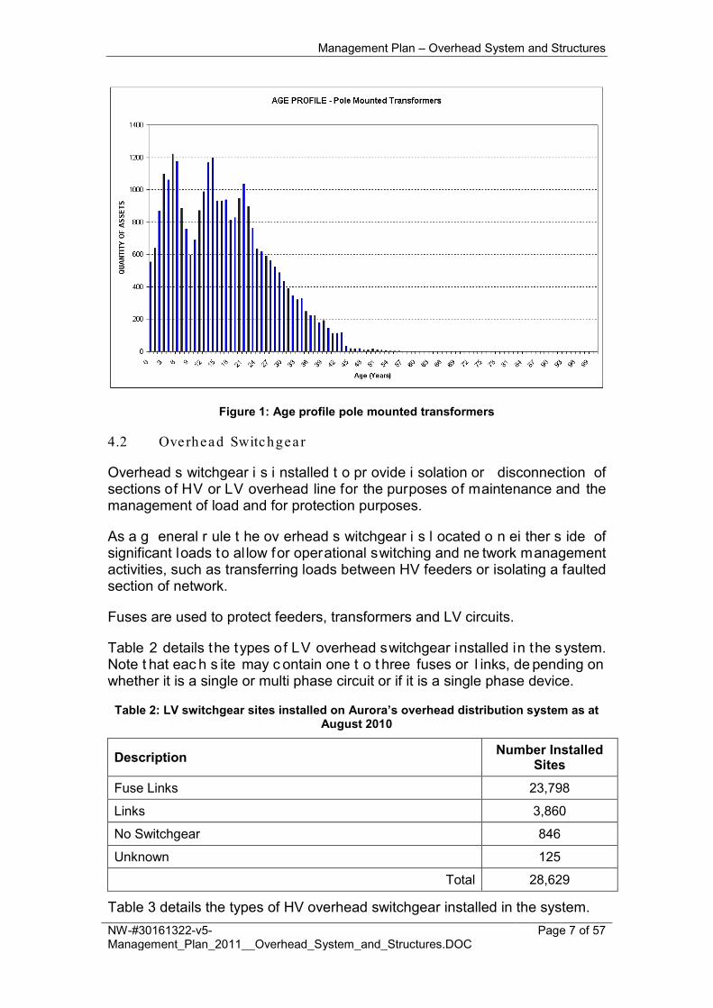
Figure 1 shows the age profile of the pole mounted transformers installed in the system.
Management Plan – Overhead System and Structures
NW-#30161322-v5-Management_Plan_2011__Overhead_System_and_Structures.DOC
Page 7 of 57
Figure 1: Age profile pole mounted transformers
4.2 Overhead Switchgear
Overhead s witchgear i s i nstalled t o pr ovide i solation or disconnection of sections of HV or LV overhead line for the purposes of maintenance and the management of load and for protection purposes.
As a g eneral r ule t he ov erhead s witchgear i s l ocated o n ei ther s ide of significant loads to al low for operational switching and ne twork management activities, such as transferring loads between HV feeders or isolating a faulted section of network.
Fuses are used to protect feeders, transformers and LV circuits.
Table 2 details the types of LV overhead switchgear installed in the system. Note t hat eac h s ite may c ontain one t o t hree fuses or l inks, de pending on whether it is a single or multi phase circuit or if it is a single phase device.
Table 2: LV switchgear sites installed on Aurora’s overhead distribution system as at August 2010
Description Number Installed Sites
Fuse Links 23,798
Links 3,860
No Switchgear 846
Unknown 125
Total 28,629
Table 3 details the types of HV overhead switchgear installed in the system.
Management Plan – Overhead System and Structures
NW-#30161322-v5-Management_Plan_2011__Overhead_System_and_Structures.DOC
Page 8 of 57
Table 3: HV Switchgear sites installed on Aurora’s distribution system as at August 2010
Description Number Installed
HV links 2,093
Air Break Switches (ABS) 4,219
Expulsion Drop Out (EDO) fuses 6,665
Gas or vacuum enclosed switches 104
Auto-reclosers – oil insulated (OYT) 13
Auto-reclosers – gas insulated (ESR) 1
Auto-reclosers – gas insulated (NULEC) 274
Sectionalisers 214
Total 13,583
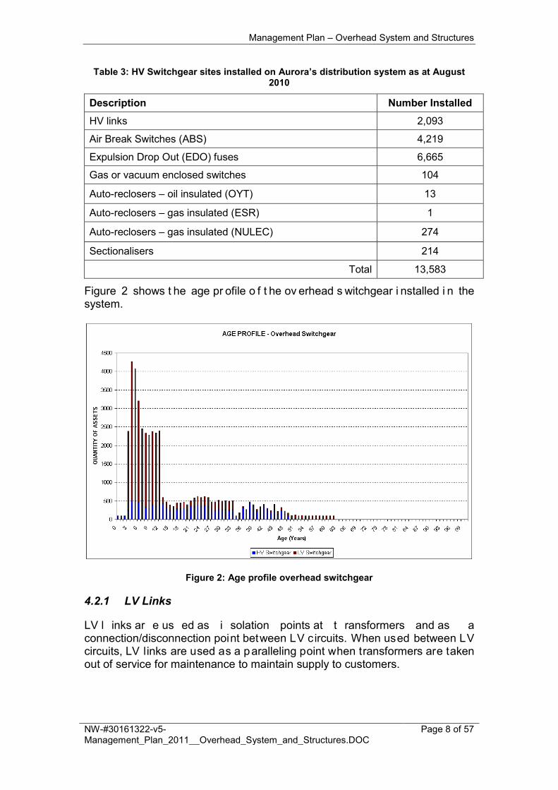
Figure 2 shows t he age pr ofile o f t he ov erhead s witchgear i nstalled i n the system.
Figure 2: Age profile overhead switchgear
4.2.1 LV Links
LV l inks ar e us ed as i solation points at t ransformers and as a connection/disconnection point between LV circuits. When used between LV circuits, LV links are used as a paralleling point when transformers are taken out of service for maintenance to maintain supply to customers.

Management Plan – Overhead System and Structures
NW-#30161322-v5-Management_Plan_2011__Overhead_System_and_Structures.DOC
Page 9 of 57
4.2.2 LV Switch Fuses
LV switch f uses can be used as both a l ink and a fuse. They are used as isolation points at transformers and to protect LV circuit from faults.
4.2.3 HV Links
HV links are single phase devices and have a s ingle break action. T hey are installed as a set of three for use on three phase systems.
HV links are not rated for breaking current. They are used to enable a piece of equipment or line to be isolated from the rest of the system.
HV links may be mounted vertically, horizontally upright or under slung.
4.2.4 HV Air Break Switches (ABS)
Air Break Switches (ABS), also known as ganged isolators, are three phase devices and have a s ingle break action. They have an operating handle that may be locked in either the open or closed position.
ABSs are not rated for breaking fault current but are designed to break load current. They are used to enable a piece of equipment or line to be isolated from the rest of the system.
Each ABS has its own earthing system. The operating handle and HV cross arm must b e c onnected t o t he earthing s ystem. The o perating han dle i s mounted five metres above ground for operator safety and security.
4.2.5 Expulsion Drop Out (EDO) Fuses
Expulsion Drop Out (EDO) fuses consist of a porcelain insulator with a hinged fibre tube held in place by a fusible link. When the EDO experiences an over current, the fusible link melts releasing the hinged tube causing it to drop open to is olate the equipment i t i s pr otecting an d at t he s ame t ime g ive a c lear indication of fuse operation.
EDOs are used to protect pole mounted transformers and spur lines.
4.2.6 Gas or Vacuum Enclosed HV Switches
Gas or vacuum enclosed switches are three phase switching devices with the ability to make and break load currents. They are not rated for breaking fault current.
Gas or vacuum enclosed switches are installed where there is a requirement to op en or c lose s witchgear when f eeders a re ener gised a nd h ave l oad on this, such as during paralleling operations.
Management Plan – Overhead System and Structures
NW-#30161322-v5-Management_Plan_2011__Overhead_System_and_Structures.DOC
Page 10 of 57
4.2.7 Auto-Reclosers
Many faults in overhead systems are transient in nature. A transient fault is a fault t hat i s no l onger present i f t he power is di sconnected for a short t ime. Causes of t ransient f aults include momentary vegetation contact, windborne materials s uch as b ark, bi rd or a nimal c ontact, c onductors c lashing due t o high winds and lightning strikes.
Auto-reclosers, also known as reclosers, are combined protection and c ircuit breaker devices that are designed to attempt to restore power in the event of a transient fault.
On detecting a fault on a s ection of l ine, an auto-recloser will open to isolate the fault. It w ill t hen m ake a n umber o f pre-programmed at tempts t o re-energise t he l ine. I f the t ransient f ault ha s cleared, the aut o-recloser w ill remained c losed a nd normal op eration of t he l ine r esumes, however, i f t he fault i s a per manent fault, t he au to-recloser w ill ex haust i ts c ount of r e-energisation attempts and lock-out leaving the faulted line isolated.
Reclosers ar e g enerally i nstalled o n r ural ov erhead feeders. T hey ar e installed with remote control and monitoring facilities.
4.2.8 Sectionalisers
Sectionalisers ar e de vices t hat w ork i n c onjunction w ith au to-reclosers t o attempt to restore supply back to some customers automatically in the event of a fault.
Sectionalisers are located downstream of auto-reclosers and monitor the fault current and c ircuit i nterruption o f t he upstream a uto-reclosers. A fter a pre-programmed n umber of a uto-recloser re -energisation at tempts, t he sectionaliser w ill open d uring t he open period o f t he auto-recloser in a n attempt to i solate a p otentially f aulty section o f l ine. I f the fault was on t he section of l ine downstream from t he s ectionaliser, t he next aut o-reclose r e-energisation attempt will successfully re-energise the section of l ine between the auto-recloser and the sectionaliser.
Sectionalisers are not rated for breaking current so they must open during the open cycle of the upstream auto-recloser.
4.3 Overhead Conduc tors and Cables
Overhead conductors provide the means for electricity to be t ransported over medium t o l ong distances i n ur ban and r ural ar eas ac ross the distribution network system.
Table 4 details t he t ypes o f ov erhead c onductor and c able i nstalled i n t he system.
Management Plan – Overhead System and Structures
NW-#30161322-v5-Management_Plan_2011__Overhead_System_and_Structures.DOC
Page 11 of 57
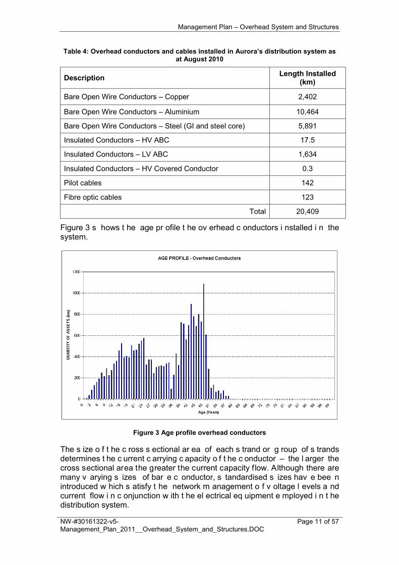
Table 4: Overhead conductors and cables installed in Aurora’s distribution system as at August 2010
Description Length Installed (km)
Bare Open Wire Conductors – Copper 2,402
Bare Open Wire Conductors – Aluminium 10,464
Bare Open Wire Conductors – Steel (GI and steel core) 5,891
Insulated Conductors – HV ABC 17.5
Insulated Conductors – LV ABC 1,634
Insulated Conductors – HV Covered Conductor 0.3
Pilot cables 142
Fibre optic cables 123
Total 20,409
Figure 3 s hows t he age pr ofile t he ov erhead c onductors i nstalled i n the system.
Figure 3 Age profile overhead conductors
The s ize o f t he c ross s ectional ar ea of each s trand or g roup of s trands determines t he c urrent c arrying c apacity o f t he c onductor – the l arger the cross sectional area the greater the current capacity flow. Although there are many v arying s izes of bar e c onductor, s tandardised s izes hav e bee n introduced w hich s atisfy t he network m anagement o f v oltage l evels a nd current flow i n c onjunction w ith t he el ectrical eq uipment e mployed i n t he distribution system.
Management Plan – Overhead System and Structures
NW-#30161322-v5-Management_Plan_2011__Overhead_System_and_Structures.DOC
Page 12 of 57
The v arying t ypes a nd s izes of overhead c onductor i s a l egacy of t he changing customer supply requirements, cost constraints, improvements and efficiencies in technology, the refinement of planning tools/models and design standards of the day.
4.3.1 Bare Open Wire Conductors
The most commonly used type of conductor installed in the overhead system is bar e open w ire t ype c onductor. T he support s tructures an d pol e t op equipment are des igned t o keep conductors at a h eight t hat i nsulates them from the ground and general public.
HV bar e ope n w ire c onductor i s by f ar t he eas iest an d m ost c ost ef fective conductor to augment, replace and install of the conductors presently in use within the industry.
The current standard materials used as bare open wire conductors are:
• All Aluminium Conductor 19/3.25 AAC (Neptune)
• All Aluminium Conductor 7/4.50 AAC (Mercury)
• All Aluminium Alloy Conductor 7/3.00 AAAC (Fluorine)
• Steel Conductor 3/2.75 SC/GZ
Other legacy materials found in the overhead system but no l onger installed include:
• Aluminium C onductor S teel R einforced ( ACSR/GZ): m ulti-strand conductor with a strengthening galvanized steel core
• Copper (Cu): multi-strand conductor
• Galvanised I ron ( GI): bot h s ingle s trand ( such as N o.8 G I) an d m ulti-strand (such as 3/12 GI)
4.3.2 Aerial Bundled Cable (ABC)
Aerial Bundled Cable (ABC) is an insulated overhead conductor of either two or t hree w ire bun dled or t wisted c onfiguration. B oth H V an d L V ABC a re installed within the distribution system.
ABC can reduce safety and bus hfire r isks, m inimise t he vegetation c learing around t he ov erhead pow erlines and i mprove s upply reliability t hrough minimising the impacts of vegetation, birds, animals and windborne objects on the overhead powerlines.
LV A BC i s A urora’s s tandard c onductor for any new LV n etworks and t he replacement of existing LV networks unless the LV ABC is unsuitable, such as for long single phase spans. In this situation, bare overhead LV conductor is used.
Due to problems w ith installation l eading to greater costs o f i nstallation, HV ABC i s pr imarily i nstalled i n s elective l ocations, s uch as h eavily vegetated

Management Plan – Overhead System and Structures
NW-#30161322-v5-Management_Plan_2011__Overhead_System_and_Structures.DOC
Page 13 of 57
areas or areas prone to wind and bird and animal affected areas to reduce the impact of these on the overhead system.
4.3.3 Covered Conductors
Covered C onductor differs from H VABC i n t hat H VABC i s a fully s creen insulated c able c onsisting o f t hree p hases wrapped ar ound a c atenary w ire while C overed C onductor ( CC) i s a s ingle core u nscreened self s upporting cable with an XLPE insulation thickness of 2mm. If the insulation thickness is equivalent t o t hat r equired for t he r ated v oltage i t i s t ermed C CT ( Covered Conductor) T hick. H VABC i s t ouch s afe w hile c overed c onductor, bot h C C and CCT, is not.
PVC is the predominant material used as the insulating cover on LV service cables.
Covered c onductors ar e pr imarily us ed f or t he ov erhead s ervice c ables connecting the customer’s installation to the LV distribution network. There is a small amount of LV covered conductor used elsewhere in the system.
The use o f covered HV conductors i s being investigated as a c ost e ffective solution as i t has p otential t o r educe t he i mpact o f v egetation, wind and wildlife o n t he ov erhead s ystem. H owever, t here ar e c urrently in stallation issues to be overcome before it can be used in the system.
4.3.4 Pilot Cables and Fibre Optic Cable
Pilot cables are used for protection and control between various d istribution substations within Hobart’s central business district.
Fibre op tic c ables ar e us ed for pr otection and c ontrol b etween T ransend Networks’ 110/ 33 k V s ubstations an d A urora E nergy’s urban z one substations.
4.3.5 Earthing Conductors
Earthing conductors are used to connect non-current-carrying metallic parts of overhead system e quipment, s uch as pole mounted t ransformer t anks a nd switchgear operating handles, to the HV earthing system (refer Section 4.6). They provide a low impedance path for the flow of earth fault current into the ground for the reliable operation of protection devices, and they help to control voltage rises associated with faults.
4.4 Fixtures and Fittings
4.4.1 Insulators
The insulators provide an i nsulated means of attaching the conductors to the poles. The type of insulator, size and make used are dependent on the level of voltage of the conductors, the design requirements of the overhead line and various ex ternal i nfluences s uch as p ollution, w eather c onditions, a nd geographic location.
Management Plan – Overhead System and Structures
NW-#30161322-v5-Management_Plan_2011__Overhead_System_and_Structures.DOC
Page 14 of 57
Generally HV and LV insulators are porcelain or g lass and bolt to the c ross arm or pole by the means of a steel pin or bolt.
4.4.2 Cross arms
Cross ar ms are used to c onnect t he i nsulators t o the s tructure a nd provide adequate clearance between conductors.
HV cross arms are steel while the LV cross arms are predominantly wooden.
HV c ross ar ms are s teel as i t offers t he s tructural i ntegrity t o w ithstand t he high conductor load tensions and associated loads imposed.
LV cross arms are predominantly manufactured from timber as this medium is cost e ffective a nd o ffers i nsulation qualities to al low l ive l ine ac tivities t o be performed safely.
4.4.3 Conductor Fittings
Conductor fittings ar e us ed t o s ecure c onductors t o t heir s upports an d for connections b etween c onductors. V arious t ypes of fittings ar e us ed depending on t he s ize and t ype o f conductor t o be joined, the geographical and el ectrical l ocation w ithin t he n etwork an d el ectrical l oading o f t he conductors.
The g eneral methods of c onnection i nclude w elds, c ompression, bol ted o r tension methods.
Bare ov erhead c onductors ar e attached t o i nsulators us ing c onductor t ies. The ties are generally the same material as the conductor.
4.4.4 Fault Indicators
Fault i ndicators ar e m ounted o n c onductors i n s trategic l ocations within t he distribution s ystem t o aid i n fault l ocation. When t he unit de tects an ov er-current, a light on the unit starts flashing to allow an operator patrolling the line to see that the fault is down stream of that location.
4.4.5 Surge Arresters
Surge arresters are installed to prevent damage to equipment in the event of a direct lightning strike on the overhead system.
Generally s urge ar resters ar e i nstalled on s pecific eq uipment, s uch as pole mounted transformers, however the surge arresters may also be placed in the overhead system at strategic locations prone to lightning strike.
HV ABC installations and where underground cable connects to the overhead system are examples of locations where lightning arresters would be installed.

Management Plan – Overhead System and Structures
NW-#30161322-v5-Management_Plan_2011__Overhead_System_and_Structures.DOC
Page 15 of 57
4.4.6 Bird Diverters
Swans, g eese, w aterfowl and other l arge bi rds c ommonly c ollide w ith conductors. Bird di verters ar e i nstalled t o make c onductors more v isible t o birds. Birds cause over 400 outages a year on Aurora’s distribution system.
4.4.7 Aircraft Warning Markers
Aircraft w arning m arkers ar e i nstalled o n c ertain ov erhead c onductors a nd equipment t o warn ai rcraft pi lots a bout the presence of high o bjects. U nder AS/NZ 3891.1-2008 (reference 14) requires any conductor installed more than 90 metres above the ground or with a span length longer than 1500 metres to be m arked w ith A ircraft w arning m arkers. T his s tandard al so r equires any overhead line installed within specified limits of a CASA registered air port to be marked.
AS/NZ3891.2-2008 ( reference 15) s pecifies t he r esponsibilities of pi lots regarding line marking.
4.4.8 Live Line Clamps
In the past, live line clamps were used to connect new transformers directly to HV feeders without requiring an outage. This connection was intended to be a temporary connection and t o be changed to a ‘ D-clamp’ at the next planned outage. However, records were not well kept of installations connected using live line clamps and many were not changed to D-clamps and it is estimated that there are approximately 10,000 live line clamps still connected (according to the WASP defect pool).
The connection o f a l ive l ine c lamp di rectly onto a l ive t ensioned conductor can r esult i n arcing, e roding i ndividual s trands o f t he c onductor a nd g reatly reducing its strength. The risk is greater for Galvanised Iron (GI) conductor as this ar cing c an r emove t he g alvanising, which exposes t he i ron t o m oisture build up underneath the c lamp. This r esults i n c orrosion o f t he conductor, which will lead to conductor failure or the fusing of the conductor to the clamp.
4.5 Struc tures
Structures provide support, insulation and adequate c learances between the overhead c onductors, ov erhead s witchgear and pole mounted t ransformers and the ground, vegetation and building infrastructure.
There are four main types of structure are used in the distribution system:
1. Wood poles (natural and treated); 2. Steel and concrete poles (commonly known as Stobie poles); 3. Spun concrete poles; and 4. Steel structures, including:
a. Steel lattice poles; b. Steel lattice towers;

Management Plan – Overhead System and Structures
NW-#30161322-v5-Management_Plan_2011__Overhead_System_and_Structures.DOC
Page 16 of 57
c. Railway section (RSJ) steel poles; d. Round steel service poles; and e. Square section steel service poles.
Accessories associated with structures are:
1. Stays; 2. Stakes; 3. Pole Operating Platforms; 4. Fauna g uards ( such as pos sum g uards, c attle/horse g uards a nd bi rd
perches) 5. Anti-climbing barriers; 6. Easements and way-leaves; and 7. Access tracks.
There ar e s ome s tructures t hat ar e j oint us e w ith ot her s ervices s uch as communications cables and road lighting.
Table 5 details the types of structures installed in the system.
Table 5: Structures installed in Aurora’s distribution system as at August 2010
Description Number Installed (Aurora owned)
Wood (Natural) Poles 4540
Wood (Treated) Poles 197075
Steel and Concrete (Stobie) Poles 6617
Spun Concrete Poles 57
Steel Lattice Poles 1355
Steel Lattice Towers 177
Railway Section (RSJ) Steel Poles 234
Steel Service Poles 12849
Total 222,904
Figure 4 shows the age profile of the structures installed in the system.

Management Plan – Overhead System and Structures
NW-#30161322-v5-Management_Plan_2011__Overhead_System_and_Structures.DOC
Page 17 of 57
Figure 4 Age profile structures
4.5.1 Wooden Poles
Natura l Wood Poles
Natural wood poles come from an untreated eucalypt sourced from Tasmania. Aurora s ourced n atural w ood pol es w ere o f t he ‘ ironwood’ ( Eucalyptus siberius) s pecies pr ocured u nder c ontract from t he S t M ary’s di strict u ntil 1994. These were originally sourced from old growth forest but in later years moved to regrowth. It was soon discovered that regrowth wood had pole integrity issues due to an increased susceptibility to heart rot. This has resulted in historical failures of natural wood poles with a life as little as seven years. Natural wood poles have no preservative and therefore the sap wood is prone to deteriorate very quickly especially below ground level. The sapwood is not included in the calculation of pole strength on these poles. Copper-Chrome-Ars ena te (CCA) Wood Poles
The t reated w ood poles us ed i n t he di stribution s ystem are h arvested and treated l ocally. T hese pol es ar e t ypically N atural D urability C lass 3 an d 4 timbers (as per AS5604 Timber – Natural Durability Ratings), as there are no Natural Durability Class 1 and 2 poles grown within Tasmania. Natural Durability C lass 3 and 4 t imbers are l ess dense and more prone to decay and have a shorter probably life expectancy than the Natural Durability Class 1 and 2 timbers typically used in mainland Australia. The t reatment us ed on t he p oles i s pr essure i mpregnated C opper-Chrome Arsenate (CCA). The average treatment applied has increased over time, as indicated in Table 6.

Management Plan – Overhead System and Structures
NW-#30161322-v5-Management_Plan_2011__Overhead_System_and_Structures.DOC
Page 18 of 57
Table 6: Level of CCA treatment
Average Treatment (kg/m3)
Minimum Treatment (kg/m3)
Pre-1970 10 6.5
1971-1980 12 8
1981-1994 15 10
Post-1994 24 18
Wood poles are purchased with a metal pole cap attached over the top of the pole to reduce the ingress of water from the top of the pole through the pole centre assisting pole decay.
CCA w ood pol es ar e c onsidered to be c ost e ffective an d also a fford a significant insulation medium for bare overhead lines.
Analysis has been performed comparing the annual equivalent cost for Class 1 and 2 wooden poles, Class 3 and 4 wooden poles, concrete poles and steel poles. The analysis demonstrates that class 3 and 4 CCA wood poles are the most cost effective option for Aurora. R efer to NW-#30103252 Structures – Annual Equivalent Calculation (reference 13).
4.5.2 Concrete and Steel, Spun-concrete and Steel Structures
These t ypes o f poles or s tructures h ave a l onger l ife than w ood poles and require m inimal maintenance other t han t he painting or r egalvanising of t he steelwork. However they have a higher capital cost are require more careful handling during installation than wood poles.
Additionally, steel and concrete poles require all conductive components to be earthed t o e nsure g reater pu blic s afety, ef fective pr otection and s afe operational activities while working on or near the pole.
They al so r equire g reater i nsulation c onsiderations b etween t he conductors and the structure, particularly in areas where bird and wildlife interactions are an issue.
Railway section (RSJ) steel poles are second hand railway steel sections that were used in the past for service poles, cross-over poles and private poles.
Steel section poles are predominately used as service poles on the LV system as they have a small footprint on the streetscape and are easily manhandled in difficult situations.
4.5.3 Stays
Poles and structures are graded by their ability to withstand the forces placed on them by conductors and pole m ounted equipment. Where t he nat ural strength o f t he p ole or s tructure i s i nadequate t o w ithstand t hese f orces, additional measures such as stays and guys are used in conjunction with the pole or structure.

Management Plan – Overhead System and Structures
NW-#30161322-v5-Management_Plan_2011__Overhead_System_and_Structures.DOC
Page 19 of 57
4.5.4 Stakes
Wooden poles deteriorate at a greater rate below the ground line than above. Thus, the above ground section may have many years o f useful service left once the below ground section has deteriorated.
Stakes ( or g round-line r einforcing) m ay b e i nstalled on w ood pol es t o strengthen the pole at and below ground level and prolong the service life of the pole by at least 15 years.
4.5.5 Pole Operating Platforms
Pole operating pl atforms pr ovide a s afe w orking pl atform for ov erhead l ine workers working on t he overhead s ystem. E levated w ork pl atforms also provide the same function.
4.5.6 Fauna Guards
Fauna guards are accessories installed on a structure to prevent animals and birds interfering with electricity assets and include:
• Possum guards;
• Cattle/horse guards; and
• Bird perches.
Possum g uards ar e installed o n w ooden poles c arrying uni nsulated H V conductors a nd eq uipment t o prevent p ossums from c limbing up t he p oles. When a pol e i s s tayed, s tay s ighters ar e i nstalled o n t he s tay t o pr event possums from climbing the stay.
Cattle/horse guards are installed on stayed poles located in areas access by livestock to prevent the livestock from scratching themselves against the pole stay.
Certain birds such as raptors (Eagles, Hawks and Kites) tend to use poles and cross arms to perch and survey the surrounding area to hunt and prey. B ird perches are installed on steel poles to provide a safe location on the pole for the bird to land without risk of contact with live conductors.
4.5.7 Anti-climbing Barriers and Signage
Anti-climbing b arriers and s ignage ar e r equired for s teel l attice t ower t o discourage and prevent unauthorised access onto these structures.
ENA G uidelines for D esign an d M aintenance o f O verhead D istribution an d Transmission Lines C(b)1 (reference 2), Section 8.4.3 requires that:
Provision shall be m ade on al l climbable structures for the fixing of signage and dev ices to ens ure the p rotection of t he publ ic f rom hazards associated with access to electrical works, and t o provide public awareness of operational safety issues

Management Plan – Overhead System and Structures
NW-#30161322-v5-Management_Plan_2011__Overhead_System_and_Structures.DOC
Page 20 of 57
4.5.8 Access Tracks
Due to the wide variety of terrain that Aurora’s distribution network covers, the construction a nd maintenance of ac cess t racks ar e v ital t o ens ure A urora’s employees can safely access distribution assets for routine maintenance as well as em ergency f ault s ituations. R epairs t o t rack s urfaces an d dr ainage structures enable safer travel with improved response times for outages.
There ar e al so specifically designated clean and unc lean sites, f arms an d areas with respect to weed and disease around the state. This heightens the need to exercise care when travelling between these areas with respect to the spread of w eeds a nd di sease. Without appropriate c are, A urora’s ac tivities can contribute to the spread of weeds, such as gorse outbreaks in gorse-free areas within Aurora’s easements.
4.5.9 Easements and Way-leaves
To ensure appropriate access for operational and maintenance activities on the overhead system and structures, specific easements and way-leaves are established to cover the route of the overhead l ine and access to and along that route. T hese eas ements ar e generally established f or the pur pose o f distribution of electricity and its associated electrical infrastructure.
Not all easements or way-leaves have been placed on property titles, however the Electrical Transitions A ct 1 996 ( reference 16) w as es tablished for easements existing prior to November 1996.
The E lectrical E asements A ct 2000 ( reference 17) r atified t his ac t. A ll easements p ost N ovember 19 96 are r equired t o be formally pl aced on property titles where the asset is owned by Aurora Energy and it crosses over private property.
4.6 Earth ing Sys tem
Pole mounted t ransformers, H V l ightning ar resters and t he ex posed metalwork of al l H V equipment i s c onnected t o a n earthing s ystem. The earthing system is essential for maintaining personnel and public safety and for c orrect oper ation of pr otection eq uipment. T he fault l evel, protection clearing time and site soil resistivity dictate the extent of the earthing required.
The earthing system for overhead equipment is typically a series of earth rods driven into the ground and connected by copper conductor.
The ear thing is o f particular importance in maintaining supply and for safety with a S WER reticulation system as t he ear th i s used as t he return current path.

Management Plan – Overhead System and Structures
NW-#30161322-v5-Management_Plan_2011__Overhead_System_and_Structures.DOC
Page 21 of 57
5. FACTORS INFLUENCING ASSET MANAGEMENT STRATEGIES
The pr inciple factors influencing asset management s trategies are c lassified as per objectives set out in Section 2.
5.1 Minimis e Cos t of Supply to the Cus tomer
• Ensuring cost e ffective t rade-offs ar e made bet ween pr o-active an d reactive maintenance practices;
• Undertaking m aintenance ac tivities t hat cost e ffectively ens ure a reasonable service life is achieved from the asset;
• Capturing ad equate i nformation on the assets t o facilitate i nformed decision making;
• Pursuing m ore c ost effective o ptions t o r eplacements, s uch a s pol e staking; and
• Ensuring al l r isks are identified and have adequate management plans integrated into the business’ practices.
5.2 Mainta in ing Ne twork Performance
• Targeting as set m anagement ac tivities appr opriately t o t he di fferent parts of t he n etwork t hat hav e v arying i mpacts o n c onsumer s ervice levels to ensure that the most cost effective solution is achieved;
• Ensuring the general operational condition of the assets is maintained to an ac ceptable l evel f or r eliable function o f s witchgear when r equired; and
• Targeting activities in areas where targets are not being met.
5.3 Managing Bus ines s Opera ting Ris ks
• Ensuring conductors maintain safe clearances to prevent contact;
• Ensuring assets do not start a fire in identified high fire risk areas; and
• Ensuring adequate inspections are undertaken to minimise r isk of pole or conductor failure.
5.4 Complying with Regula tory, Con trac tua l and Lega l Res pons ib ilitie s
The f ollowing is a b rief description o f t he s pecific r egulatory obl igations recently introduced that directly influence Aurora’s management of overhead and structural assets.
A list of the legislation, regulations, standards and codes of practices directly relevant to the management of Overhead System and Structures is provided in Section 14.
Management Plan – Overhead System and Structures
NW-#30161322-v5-Management_Plan_2011__Overhead_System_and_Structures.DOC
Page 22 of 57
5.4.1 Changes to the Occupational Licensing Act 2005
Changes to the Occupational Licensing Act 2005 (reference 18) that became effective on 1 9 J anuary 2009 r equire A urora t o b e c ompliant with C (b)1 (reference 2) i n t he construction an d oper ation o f i ts di stribution net work. Before this date, C(b)1 was taken as standard industry practice for design and construction of distribution networks in Australia.
5.4.2 Sulphur Hexafluoride (SF6)
Aurora c urrently has ov er 300 pol e m ounted s witchgear s ites w ith S F6 insulation.
In recent times concerns with the impact this green house producing gas has on t he e nvironment h as r esulted i n t he i ntroduction o f r equirements f or t he reporting and disposal of SF6.
Aurora i s r equired t o c omply with T he N ational G reenhouse a nd E nergy Reporting A ct 2 008 ( reference 19), w hich s et ou t a n ational framework f or corporations t o r eport g reenhouse g as e missions and e nergy c onsumption and production from 1 July 2008.
Disposal o f S F6 is managed i n ac cordance w ith A urora’s E nvironmental procedure E W-M12-01 D isposal o f S F6 (reference 20) w hich r eflects t he requirements o f t he N ational E nvironment Protection M anagement M easure (NEPM) and t he E nvironmental M anagement P ollution C ontrol A ct 19 94 (references 21 and 22).
5.4.3 Polychlorinated Biphenyls (PCBs)
Aurora manages PCBs in accordance with Aurora’s Environmental procedure EM-M09 M anagement o f P CB’s ( reference 23), w hich r eflects t he requirements o f t he A ustralian and N ew Z ealand Environment a nd Conservation C ouncil ( ANZECC) P olychlorinated B iphenyls M anagement Plan (reference 24). Both plans satisfy the legislative requirements of the TAS Environmental Protection & Pollution Act 1994 and the NEPM standards Act (references 25 and 26).
Polychlorinated bi phenyls ( PCBs) were us ed i n t ransformers a nd c apacitors amongst other things from the 1930s to the 1970s. However, they were shown to be toxic and carcinogenic and have been banned in Australia in the 1970s.
As part of the routine switchgear maintenance, i f asset records indicate that the status of the oil in a transformer is ‘unknown’ then a sample of oil is taken from t he t ransformer f or P CB t esting. I f t he P CB t est r esults i ndicate P CB
CONFIDENTIAL
Management Plan – Overhead System and Structures
NW-#30161322-v5-Management_Plan_2011__Overhead_System_and_Structures.DOC
Page 23 of 57
levels eq ual t o or g reater t han 50 p pm, t he t ransformer i s pr oposed for removal from the system.
6. MANAGEMENT P LAN
6.1 Trea tment Trade-offs
6.1.1 Preventative versus Corrective Maintenance
There i s a f undamental r equirement f or A urora t o per iodically i nspect i ts assets to ap propriately and effectively t arget pr eventative m aintenance programs and to ensure the physical state and condition of the asset does not represent a hazard to the public.
Other than v isiting the assets, there is no other economic solution to satisfy this requirement. Land based inspection is the only practical way to monitor decay r ates i n p oles, but t here ar e v arious m onitoring t echniques c an b e utilised. Aerial and land based surveys of conductors, fixtures and switchgear are both possible.
Corrective m aintenance o n p oles i ncurs a c onsiderably hi gher cost t han preventative m aintenance, an d c an i mpact c onsumer s ervice l evels significantly. G iven t hat w eather c onditions ex ceed design s tandards from time to time, a portion of corrective maintenance is always expected. The key trade-off A urora m onitors i s t he c ost i ncurred i nspecting p oles v ersus t he premium incurred from corrective maintenance, and more importantly the level of impact on consumer service levels.
For s ome assets s uch as s urge ar restors and ov erhead L V A BC c ables, deterioration o f c omponents ar e v ery di fficult t o i dentify and/ or pr ovide preventative m aintenance s trategies. I n t hese s ituations corrective maintenance an d/or asset r eplacement i s c onsidered a v iable al ternative (subject to assessing fire and other risk factors).
6.1.2 Asset Replacement
Planned asset replacements are driven by condition based assessments from the Aurora’s preventative maintenance programs. Where weather conditions are extreme, or third parties cause damage to overhead and structural assets, reactive replacements are required.
A key initiative Aurora employs to defer asset replacement is the practice of pole staking. This practice is believed to extend the life of the asset by up to and in excess of 15 years.
OH t ransformers an d switchgear t hat are r emoved from t he network du e to other w ork ac tivities are al so as sessed for r efurbishment a nd s ubsequent redeployment back into the network.
Management Plan – Overhead System and Structures
NW-#30161322-v5-Management_Plan_2011__Overhead_System_and_Structures.DOC
Page 24 of 57
6.1.3 Non Network Solutions
Consideration of mobile generation to minimise consumer disruption on failure of ov erhead as sets i s s ometimes a v iable al ternative t o i nvesting i n reinforcement and redundancy assets. The nature and scale of the connected load and consumer type are important when considering this alternative.
6.2 Preventa tive Main tenance Programs
6.2.1 Structures Inspection and Monitoring
Aurora’s inspection and monitoring program consist of four components:
1. Inspection and testing of structures; 2. Sample inspection of steel towers; 3. Non-destructive evaluation; and 4. Graffiti removal – agreements with external parties.
There are no major changes to this program and the proposed expenditure is to remain consistent with historical spend.
Ins pec tion and Tes ting of Struc tures
Inspection of structures is undertaken on a 3 .5 year cycle in accordance with Network P olicy NN R A M 05 I nspection a nd M aintenance of D istribution Overhead Lines (reference 5).
The inspection cycle for other Australian utilities is currently a four to four and a hal f y ear c ycle. T he m ain r eason for t his difference i s t he c lass o f w ood used for power poles. The majority of poles installed on the mainland are of Class 1 and 2, which means that they are extremely dense and less prone to decay. Tasmanian t imbers on t he other hand are sourced locally and ar e of Class 3 and 4 timbers as there are no Class 1 and 2 grown within the state.
CONFIDENTIAL
CONFIDENTIAL
CONFIDENTIAL

Management Plan – Overhead System and Structures
NW-#30161322-v5-Management_Plan_2011__Overhead_System_and_Structures.DOC
Page 25 of 57
The results of the tests undertaken during this inspection determine whether a pole is:
1. Serviceable – considered to be in an adequate condition to safely remain in service until the next pole inspection;
2. Impaired – not c onsidered t o be i n an a dequate c ondition t o safely remain i n s ervice unt il t he nex t p ole i nspection, but s uitable t o b e considered for staking (it may then be condemned if it does not meet the detailed staking criteria); or
3. Condemned – not considered to be i n an adequate condition to safely remain i n s ervice unt il t he nex t pol e i nspection an d not s uitable f or staking.
To slow the rate of deterioration of wood poles, the application of boron pole saver r ods and b andages t o t reat w ooden pol es for h eart a nd soft r ot ar e undertaken as part of the pole inspection program. Figure 4 in Section 4.5 shows the age profile of wooden poles and identifies that going into the next determination period a large number of wooden poles move i nto t his r ange; s o i t i s ex pected t hat t hese p oles w ill need t o b e replaced.
As overhead lines and equipment are inspected as part of the pole inspection, the inspection cycle is a compromise between asset defect detection and pole condemning.
Appendix A.1 shows the age distribution of defective poles identified over the last decade s hows a pol e ag e of l ate 30 s t o ear ly 40s as t he av erage condemning/failure age for wooden poles.
In addition there are approximately 4500 natural wooden poles in the system, which have unpredictable characteristics and have been known to fail at early ages (under 10 years). These poles are al l between 15 and 25 years old (at 2010).
CONFIDENTIAL
CONFIDENTIAL
CONFIDENTIAL

Management Plan – Overhead System and Structures
NW-#30161322-v5-Management_Plan_2011__Overhead_System_and_Structures.DOC
Page 26 of 57
Future pole replacement will be based on:
2. Age profile of current poles (Figure 4) with significant increases in poles greater than 40 years old during the determination period
3. Expected failure o f n atural w ood poles, w hich ar e unpredictable an d reaching their expected lifetime.
Sample Ins pec tion and Trea tment of Stee l Towers
Aurora has a small population of extreme high voltage steel lattice towers in its s ystem. T he majority of t owers were i nstalled i n t he l ate 1950’s and ar e approaching t he end of t heir no minal as set l ife. A urora u ndertakes s ample inspections t o monitor t heir c ondition for pr oactive m aintenance works and undertakes minor remedial action to defer replacement expenditure.
Major remedial ac tion is undertaken under RESTK Reinforce Below Ground Portion of Tower Leg (Section 6.4.4).
In 2 006, a dedicated inspection pr ogram ( performed by I ncospec o f South Australia) assessed the condition of the legs as requiring remedial action. The above ground sections were found to be in good condition. Refer to Incospec report (reference 3).
Non-Des truc tive Eva lua tion
Current testing methods to detect the progression of the decay in wood poles are destructive (refer Network Procedure NP R AM 27.1 Pole Inspection and Maintenance (Part 1 – Wood P oles) – reference 6). T hree holes are dr illed near and below g round l ine t o de tect t he l evel of decay. The below ground test holes require the removal of material around the pole, including concrete and paved surfaces.
Aurora is currently investigating non-destructive methods of testing as part of an industry wide initiative from the Energy Networks Association Power Poles and C ross Arms C ommittee. H owever, ben efits associated w ith non -destructive technologies will need to be assessed against their cost to ensure that Aurora is investing in the most cost effective activity.
Graffiti Remova l – Agreements with Exte rna l Partie s
Aurora has a policy of removing any graffiti that is offensive to the community namely i f i t is derogatory to a par ticular race or section of the community or depicts offensive w ords or dr awings. H owever, s everal c ommunity organisations and councils have a z ero tolerance to graffiti and lobby for the removal of all graffiti from Aurora assets.
To address this issue, Aurora has negotiated with the Hobart City Council to contribute $5,000 per y ear t o t he c ouncil t o r emove g raffiti from Aurora structures and assets in the HCC environs.
CONFIDENTIAL

Management Plan – Overhead System and Structures
NW-#30161322-v5-Management_Plan_2011__Overhead_System_and_Structures.DOC
Page 27 of 57
Aurora also supplies material (such as paints) and s upervision to the Police Young Offenders Program and various Progress Associations to assist in the removal of graffiti.
6.2.2 OH System Feeder Inspections
The ov erhead s ystem c ontributes t o over 60 per cent o f t otal a sset failure contribution t o A urora’s S AIDI a nd SAIFI. A g round an d aerial auditing a nd inspection program is r equired t o al low A urora t o effectively t arget maintenance and replacement activities. This program covers activities such as:
1. Investigating outages caused by failures such as broken t ies, insulation failures or conductor clashing;
2. Determining the condition o f l arge lengths o f the ne twork w ithin a t ight time frame where there may be access issues for ground crews, such as after a storm or bushfires; and
3. Specifically g athering c ondition i nformation when as set failure t rends have been identified.
There has been a major change to this inspection program to improve the cost effectiveness o f A urora’s i nspection pr ograms. P reviously t here were f our separate inspection programs in place that were not utilised each year due to no bus iness requirement or the ut ilisation of internal resources to under take the inspections, which are no longer available.
Aurora has c onsolidated these pr ograms i nto a s ingle program w ith t he flexibility to target inspections. The proposed expenditure has decreased due to the efficiency gains.
6.2.3 OH Feeder High Vehicle Load Inspection
The hi gh l oad r oute i nspection pr ogram i s us ed t o ens ure A urora’s infrastructure isn’t damaged by transportation of high load, which is triggered by requests f rom the public. This task is generally under taken by an A urora preferred c ontractor u nder the r equest o f t he customer, h owever, A urora reserves a s mall amount o f funds to address the infrequent s ituations when customers bypass this process.
The c ost of m aintaining t his s mall i nspection pr ogram to pr otect A urora’s asset and the members of the public is seen as less than the cost to reactively repair the assets if damaged.
Aurora r ecords approximately 30 i nstances ev ery year w here t hird par ty vehicles contact/pull down overhead services.
There are no major changes to this program and the proposed expenditure is to remain consistent with historical spend.

Management Plan – Overhead System and Structures
NW-#30161322-v5-Management_Plan_2011__Overhead_System_and_Structures.DOC
Page 28 of 57
6.2.4 OH Transformers – Load and Condition Monitoring
This program covers the ac tivities associated with testing and r ecording the load on pole mounted distribution transformers greater than 200 kVA and over 80 percent loaded for capacity planning purposes and the identification of load unbalance issues over the regulatory per iod. This also includes onsite/same time visual checks of the assets and connections.
Condition i nformation enables A urora t o pr oactively r enew or m aintain t he assets, minimising the amount of reactive replacement.
The S ystem O perations g roup pr eviously managed t his pr ogram. This program has been in place for a number of years but has been underutilised in t he past. A urora pr oposes t o un dertake t his i nspection program t o determine the value of the information before assessing whether the program should be ongoing.
6.2.5 OH Feeders Thermal Inspections
This program covers the ac tivities associated with testing and r ecording the conditions of the network using a t hermal imaging device to identify potential weak spots, defects or constraints within the Network.
There are two components to this program:
1. Defined thermal inspections; and 2. General thermal inspections.
Defined Thermal Ins pec tions
This program covers the annual use of external contractors to thermally image Aurora’s critical feeders (feeders that contribute significantly to system SAIDI and SAIFI) and s ub-transmission feeders. These inspections are undertaken during the months leading up t o the winter period, namely March through to June.
Thermal i nspections a re r equired t o i dentify weak s pots an d de fects on t he critical c omponents o f t he n etwork be fore as set failure s o t hat r eactive maintenance c an be undertaken w ith l ess disruption t o c ustomers and at lower cost.
There are no major changes to this program and the proposed expenditure is to remain consistent with historical spend.
This program was previously managed by the System Operations group.
CONFIDENTIAL

Management Plan – Overhead System and Structures
NW-#30161322-v5-Management_Plan_2011__Overhead_System_and_Structures.DOC
Page 29 of 57
Genera l Thermal Ins pec tions
This program covers the use of A urora’s field s taff t o patrol l ines with hand held t hermal i maging c ameras a fter faults and s witching ope rations on Aurora’s n etwork t hat m ay hav e w eakened c omponents of t he ov erhead network.
These t hermal i nspections i dentify weak s pots an d de fects s o that r eactive maintenance c an be undertaken w ith l ess disruption t o c ustomers and at lower cost.
There are no major changes to this program and the proposed expenditure is to remain consistent with historical spend.
This program was previously managed by the System Operations group.
6.2.6 OH Transformer Earthing Inspection and Monitoring
The aim of this program is to audit the condition of overhead substation and switchgear earth connections to improve Aurora’s asset condition information and ensure compliance to AS 2067 Substations and high voltage installations exceeding 1 kV a.c and ENA EG 0 Power System Earthing Guide (references 27 and 28).
This audit w ill al so i dentify s ites for r eplacement w here ear ths have be en stolen or v andalised. I n 09/ 10, A urora r ecorded ov er 50 s ites w here transformer earths had been stolen or vandalised.
The pr oposed expenditure i s g reater t han h istorical s pend d ue t o pr evious underutilisation of the program. Aurora sees the need to increase expenditure in the future due to the increase in earth thefts and to ensure compliance to AS 20 67 a nd E NA E G 0. A urora pr oposes t o un dertake t his inspection program to determine the condition of the assets to determine the scale of the replacement program.
6.2.7 Fire Mitigation Asset Inspections
There are two components to this program:
1. Asset inspection of feeders in high fire danger areas; and 2. Audits of work completed on feeders in high fire danger areas.
CONFIDENTIAL
CONFIDENTIAL

Management Plan – Overhead System and Structures
NW-#30161322-v5-Management_Plan_2011__Overhead_System_and_Structures.DOC
Page 30 of 57
As s e t ins pec tion of feeders in h igh fire danger areas
As the pole inspection process ( refer Section 6.2.1) is focussed on the area immediately surrounding the pole and does not include a mid-span inspection, a specific fire mitigation asset inspection is undertaken annually.
The i nspection i s al so und ertaken t o s pecifically t arget as sets t hat ar e recognised fire s tart r isks t hat m ay hav e be en g iven a l ower pr iority i n t he routine l ine inspection and t o identify any asset component defects that may have occurred since the last routine inspection cycle
This inspection is undertaken by specialised staff and focuses on asset issues known t o c ontribute to fire s tarts. These i nspections feed i nto t he fire mitigation asset repair (refer Section 6.3.2) and r eplacement programs (refer Section 7.1).
For m ore d etailed i nformation o n the s election o f areas for t his i nspection program s ee N W-#30043347 Management P lan B ushfire Mitigation (Asset Programs) (reference 9).
Audits of work comple ted on feeders in h igh fire danger a reas
This program i s an a nnual au dit of t he w ork c ompleted as par t of t he fire mitigation as set r epair and r eplacement pr ograms t o ens ure t he work has been completed within the required time frames.
This i s a n ew i nspection pr ogram t o e nsure t he q uality o f A urora’s f ire mitigation works.
6.2.8 Access Track Management
There are two components to this program:
1. Access track maintenance; and 2. Weed management.
Acces s Track Main tenance
The aim of this program is to maintain access tracks to an adequate standard that Aurora staff can safely access Aurora’s assets.
Experience w ithin A urora has s hown ex isting ac cess t racks need t o be maintained a pproximately ev ery f our y ears for opt imum c ost v ersus be nefit and to stop them degrading to the stage where they require extensive works.
There ar e no m ajor changes to t his pr ogram h owever, t he pr oposed expenditure has increased compared to historical spend due to the increased number of access tracks requiring maintenance from the previous regulatory period.

Management Plan – Overhead System and Structures
NW-#30161322-v5-Management_Plan_2011__Overhead_System_and_Structures.DOC
Page 31 of 57
Weed Management
There ar e s pecifically des ignated c lean a nd unclean sites, f arms and ar eas with respect to weed and disease around the state. Although Aurora has strict weed and disease management procedures in place when travelling between these areas, the aim of this program is to reactively address situations where Aurora’s activities hav e c ontributed t o t he s pread o f w eeds, s uch as g orse outbreaks in gorse-free areas within Aurora’s easements.
This is a new program to address an emerging issue.
6.2.9 Leaning Poles
The aim of this program is to address the issue of leaning poles in Aurora’s system. A pol e i s c onsidered l eaning, an d i s a r eportable d efect when i t i s leaning more than 6º from vertical (or approximately four pole head widths out of vertical).
When a pole is leaning between 6º and 10º from vertical, there is a higher risk of c onductor c lashing, but t he pol e i tself i s s tructurally s ound. A l ean of greater t han 1 0º i ndicates t hat t he foundations o f t he p ole are potentially compromised and the pole may be in danger of collapsing.
Leaning wood poles are mainly due t o problems associated with ground and foundation s trengths, backfill m edium, c ompactness at foot and heel o f the pole and inadequate counterforce infrastructure (stays etc).
Between 2007 and 2009, an average of 227 leaning pole defects have been identified each year as part of the routine asset inspection cycle.
Currently a defect pool exists of 500 poles, and analysis of these defects has identified a r ate o f a pproximately 150 n ew leaning per y ear ent ering t he system. T his c ategory o f w ork was pr eviously done un der ov erhead asset repairs ( AROCO), hence t he backlog of defects d ue t o ot her higher pr iority tasks being completed first.
6.2.10 Repair Steel and Concrete Poles
This program aims to repair t he below ground section o f direct buried s teel and concrete poles. Steel and concrete poles (known as Stobie poles) are a composite p ole c onstructed o f t wo s teel c hannel s ections hel d apar t by strategically positioned bolts with a concrete infill. They are strong in the major axis and very weak in the minor axis.
These p oles w ere i nstalled pr edominately f rom t he 19 50s t hrough t o t he 1970s. T hey ar e v ery e xpensive t o m anufacture a nd ar e s usceptible to corrosion at or j ust below g round l ine as the s teelwork i s g enerally onl y protected by enamel paint. However they can be repaired in situ by welding a steel plate across the affected area.
Repairing the below section of direct buried Steel and Concrete poles is cost effective as it will extend their lives by 15 to 20 years.

Management Plan – Overhead System and Structures
NW-#30161322-v5-Management_Plan_2011__Overhead_System_and_Structures.DOC
Page 32 of 57
They are very good in fire prone areas but have a high bird interaction impact due to their conductivity.
They perform poorly in coastal environments where the salt laden air attacks the steel section above ground.
There are no major changes to this program and the proposed expenditure is to remain consistent with historical spend.
6.2.11 Insulator Washing and Pollution Mitigation
The aim of this program is to prevent insulation break down of the overhead insulator d ue t o pol lution b uild up i n high p ollutant ar eas s uch as i ndustrial areas or near t he c oast. R ain nor mally effectively c leans t he i nsulators however, af ter a pr olonged dry spell t he insulation can s tart t o break down, which can result in pole top fires.
The pr oposed expenditure i s g reater t han h istorical s pend d ue t o pr evious underutilisation of the program.
In recent years this program has been underutilised due to the work force not being fully trained to perform this task. New equipment and training has been provided t o c rews s o t his pr ogram c an be fully ut ilised. The an nual expenditure may vary year to year depending on the weather as this program is m ainly r equired w hen t here has been a l engthy dr y s pell ( 3-4 m onths without rain).
6.3 Correc tive Main tenance
6.3.1 Decommission Assets
Aurora ow ned as sets f rom t ime t o t ime ar e decommissioned an d disconnected f rom el ectrical s ystem. The reason for dec ommissioning i s varied, but recently has been driven by a c hange o f l and use where a farm has been converted to a t ree plantation. Aurora removes the assets from the network as l eaving t he as sets s tanding i ncurs ong oing c osts i n inspection treatment and vegetation clearing.
There are no major changes to this program and the proposed expenditure is to remain consistent with historical spend.
6.3.2 Asset Repair – Fire Mitigation
This program is for the repair of minor asset defects that are known fire starts, such as r estraining s lack c onductors or i nstalling LV s preaders t o pr event conductor clashing, that are identified during routine asset inspections and fire mitigation asset inspections.
CONFIDENTIAL

Management Plan – Overhead System and Structures
NW-#30161322-v5-Management_Plan_2011__Overhead_System_and_Structures.DOC
Page 33 of 57
Defects that c annot be s imply r epaired und er the f ire mitigation as set replacement pr ograms ( refer S ection 7.1). F or m ore detailed i nformation regarding de fects r epaired under t his pr ogram, s ee N W-#30043347 Management Plan Bushfire Mitigation (Asset Programs) (reference 9).
Replacements of EDO fuse tubes in high and very high fire danger areas have been r emoved from t his pr ogram d ue to a t argeted r eplacement pr ogram however, t he pr oposed ex penditure i s t o r emain c onsistent w ith hi storical spend as EDO fuse tubes are only a component of the program.
6.3.3 Oil Management
Aurora h as ov er 30, 000 t ransformers an d ov er 300 oi l filled s witchgear i n service in the distribution system. Predominately 28,000 of these transformers are pole mounted, each containing oil quantities ranging from 45 litres through to 720 litres. When the assets reach the end of their useful l ife the oil has to be removed and disposed of.
Pole mounted and ground mounted oil filled assets are disposed of under this category d ue t o t he greater q uantities o f pole m ounted eq uipment bei ng processed annually.
Disposal of SF6 equipment is processed under Ground Mounted Substations Asset Repair Recovery and Disposal of Redundant SF6 Switchgear due to the larger volumes of S F6 i nsulated s witchgear i n t he g round mounted s ystem. See Management Plan 2011: Ground Mounted Substations (reference 1) for more information on SF6 disposal.
Aurora is required to dispose of oil and oil-contaminated assets in accordance with A ustralian Standards. This pr ogram funds A urora’s O il F arms w ho manage the removal and disposal of oil from redundant oil-filled assets.
The pr imary obj ective i s t o r ecover oi l from as sets t hat r eached t he end of their useful l ife along with response to oi l spills, test for PCB’s and disposal according t o e nvironmental r equirements (including obt aining per mits a nd arranging transport) and disposal of oil free equipment.
There are no major changes to this program and the proposed expenditure is to remain consistent with historical spend.
6.3.4 OH System Asset Repairs
This program covers minor asset repairs that have been i dentified and hav e the potential to cause asset failure in the future or shorten the expected life of the asset. Public risk and reliability are the main drivers.
The majority o f t hese d efects ar e r eported t hrough t he P ole i nspection program ( AIOHS) and i nclude minor w ork i nvolving as set r epair s uch a s refixing l oose m aterial, r eplacing pos sum g uards, r epairing oper ating platforms, etc.
Management Plan – Overhead System and Structures
NW-#30161322-v5-Management_Plan_2011__Overhead_System_and_Structures.DOC
Page 34 of 57
Repair of leaning poles and r emoval of l ive l ine c lamps have been removed from the as set r epair pool and are being a ddresses t hrough t argeted as set repair an d as set r eplacement programs d ue t o t he l arge v olumes o f t hese defects in the system.
Aurora is also undertaking a review of its defect pool.
6.3.5 OH System Low Conductor Clearance
This pr ogram c overs s imple r epair t asks s uch as t he r e-tensioning of s lack spans of LV and HV conductor to address conductor clearance issues. Where a more complex solution is required (such as the installation of a pole), this work is undertaken as an asset replacement task (see sections 6.4.6, 6.4.24)
Aurora experiences approximately 30 i ncidents every year where third par ty vehicles contact/pull down overhead services.
6.3.6 OH Switchgear Asset Repair
There are two components to this program:
1. General asset repair of overhead switchgear; and 2. Recloser and fault indicator maintenance.
Genera l As s e t Repa ir of Overhead Switchgear
This program c overs t he minor r epair of ov erhead s witchgear s uch as replacing terminations or air break switches, relocating switchgear, repairs to recloser pole top control cubicles, etc.
Replacements of EDO fuse tubes have been removed from this program due to t he c reation o f a t argeted r eplacement program t o ad dress operational issues with the devices associated with corrosion, exposure and weathering.
The proposed expenditure is less than historical spend due to the creation of a targeted EDO fuse tube replacement program.
CONFIDENTIAL
CONFIDENTIAL
CONFIDENTIAL
Management Plan – Overhead System and Structures
NW-#30161322-v5-Management_Plan_2011__Overhead_System_and_Structures.DOC
Page 35 of 57
Reclos er and Fault Ind ica tor Main tenance
This program covers the replacement of battery units in the 1,300+ reclosers and fault indicators in Aurora’s overhead network. The batteries on these units are des igned t o l ast for appr oximately f ive y ears. B attery s upply t o t hese devices is essential for communication and operation of the device during fault conditions when the network supply is off.
Aurora has experienced c ommunication a nd op eration failures t o r eclosers during extreme weather situations due to old batteries in the devices that have delayed the restoration of power.
The pr oposed expenditure i s g reater t han hi storical s pend d ue t o m ore reclosers and fault indicators entering the system and approaching their five year battery life.
6.4 As s e t Replacement
A nu mber o f k ey r isks dr ive t he need for a sset r eplacement i n t hese as set classes.
6.4.1 Install Wildlife Protection on Transformers
This aim of this program is to protect overhead assets from damage due t o wildlife c ontact by i nsulating l ive c omponents an d par ts. The s eparation distances between conductors and pole top hardware are generally adequate to prevent current t racking down the pole to the ground. However, birds and animals oc casionally bridge t his g ap, r esulting i n phas e-to-phase contact o f the conductors and the electrocution and potential combustion of the animal.
This pr ogram i s bas ed o n as set failures and outage i nformation. A urora records ap proximately 500 o utages c aused bi rds and animals e very year (includes mid-span collisions as well).
There are no major changes to this program and the proposed expenditure is to remain consistent with historical spend.
6.4.2 Replace Transformer Earths
The aim of this program is to proactively replace transformer earths that are in poor condition or damaged and reactively replace transformer earths that are stolen or vandalised.
The transformer earths to be replaced are identified through two sources:
1. Earths identified as being in poor condition through asset inspection and monitoring programs (AIOTX); and
2. Stolen copper earths (refer Section 6.2.9).
CONFIDENTIAL

Management Plan – Overhead System and Structures
NW-#30161322-v5-Management_Plan_2011__Overhead_System_and_Structures.DOC
Page 36 of 57
2009/10 and onwards has seen a significant increase in the amount of copper earth thefts. As a result sites targeted by copper thieves now have the earths covered and s tapled to the pole when they are replaced. Records of copper theft from previous years are variable as this was not an area of focus for the business.
The pr oposed expenditure i s g reater t han h istorical s pend d ue t o pr evious underutilisation o f t he pr ogram an d t o address t he i ssues around e arthing theft a nd v andalism. A urora pr oposes t o undertake t he t ransformer e arth inspection pr ogram ( section 6.2.6) to determine t he condition o f t he assets, identify sites for repair and the future scale of this program.
6.4.3 Access Track Creation and Rebuilding
The aim o f t his program i s t o a ddress s ituations w here t he c ondition of a n access t rack i s so poor t hat i t cannot be s afely used w ithout m ajor r epairs, such as rebuilding river crossings, or where no existing access track exists.
Aurora’s t rack m aintenance pr ogram pr ior t o t he 20 08-2012 P ricing Determination was insufficient and, as a result, a number of established tracks were lost due to overgrown vegetation and erosion from waterways. Extensive work was under taken dur ing t he 2 008-2012 P ricing D etermination t o b egin rebuilding t hese t racks and ad ditional t racks for new s ections o f the distribution network. This work is still ongoing.
This program has been in place for a number of years but as part of Replace HV Feeders (Safety) (section 6.4.22).
There are no major changes to this program and the proposed expenditure is to remain consistent with historical spend.
6.4.4 Pole Staking
There are two components to this program:
1. Install pole stake – reinforce ground line of unserviceable poles; and 2. Reinforce below ground portion tower leg.
Ins ta ll P ole S take – Re inforce Ground Line of Impa ired Poles
The pur pose o f t his pr ogram i s t o de fer r eplacement o f p oles by s taking suitable p oles. As wooden p oles de teriorate at a g reater r ate b elow g round level than above reinforcement at ground level using staking technique defers the replacement of the decayed wood pole by up to and in excess of 15 years.
Whole of l ife analysis has indicated that staking is a c ost effective method of extending the life if a wooden pole (reference 7).
CONFIDENTIAL

Management Plan – Overhead System and Structures
NW-#30161322-v5-Management_Plan_2011__Overhead_System_and_Structures.DOC
Page 37 of 57
Wood p oles are s taked as per N etwork P olicy NN R A M 11 W ood p ole reinstatement by ground-line reinforcement (reference 8).
After s taking, t esting o f t he p ole c ontinues on t he us ual 3 .5 y ear c ycle, however addi tional t esting i s under taken f urther up t he pol e t o ens ure appropriate strengths are maintained above the reinforcement.
Analysis of the number of poles staked each f inancial year show that after a decrease i n 2 005/2006, t here has b een a relatively c onstant trend of pole staking i n s ubsequent y ears. T his i ndicates t hat t he d efects are bei ng appropriately m anaged and t he i nspection c ycle i s pr udent. T he r ise in condemning pol es w ill al so i nclude a c ertain p ercentage o f t he s taked population, which is contributing to the increase in that trend.
There ar e no major c hanges t o t his pr ogram an d ex penditure i n t he n ext regulatory period is based on an assumed continuation of a c onstant staking rate a nd an ex tra 5 0 pol es p er y ear t o a ccount for both t he continuing increase o f the pole po pulation a nd a n ex pected i ncrease i n de fect identification.
Defect identification will increase due to a large number of poles moving into the higher risk portion of the age profile during the determination period.
Reinforce Be low Ground Portion Tower leg
The aim of this program is to undertake major remedial works on t he below ground por tion o f Aurora’s ex treme high voltage s teel towers. As with wood poles, s teel t owers d eteriorate b elow g round at a faster r ate t han ab ove ground.
The remedial action proposed is the replacement of the below ground section of the legs. The alternative is to replace the entire steel tower structure, which is v ery c ostly. T he r emedial ac tion c osts o nly a fraction o f t he amount t o replace the entire tower and extends the life of the tower in the order of twenty to thirty years.
This program has been in place for a n umber of years but was underutilised and the issues that were raised by the inspection undertaken in 2006 largely unaddressed. Aurora proposes to re-run an inspection to determine the extent of remedial work (section 6.2.1).
6.4.5 Install Anti-climbing Barriers and Signage
The aim o f this pr ogram i s t o i nstall a nti-climbing bar riers and s ignage on certain types o f ov erhead eq uipment t o deter pu blic ac cess t o a ssets a nd comply with C(b)1 (reference 2).
The program is prioritised is based on proximity to the general public. An audit is c urrently under way ( 2010/11) t o det ermine t he s cale o f t his pr ogram however i t i s not ex pected t hat t here w ill be any m ajor c hanges t o t his program and the proposed expenditure is to remain consistent with historical spend.
Management Plan – Overhead System and Structures
NW-#30161322-v5-Management_Plan_2011__Overhead_System_and_Structures.DOC
Page 38 of 57
Aurora aims to achieve full compliance by 2016/2017.
6.4.6 Replace/Relocate Low LV Conductors
This program covers the relocation or replacement of LV overhead conductor to address low c learances associated with road c rossings and plant contact that c annot be repaired un der t he r eactive m aintenance pr ogram ( section 6.3.5) such as the installation of a pole to fix the clearance issue.
Aurora experiences approximately 30 i ncidents every year where third par ty vehicles contact/pull down overhead services.
6.4.7 Replace/Relocate LV OH due to Building Clearances
This program c overs r elocation or r eplacement LV ov erhead c onductor because o f i ssues w ith bui lding c learances e. g. when new bui ldings are erected that infringe on Aurora’s clearance, that cannot be repaired under the reactive maintenance program (section 6.3.5).
This program has two components:
1. Relocating or replacing with LV ABC; and 2. Replacing with underground cable.
Aurora experiences approximately 30 i ncidents every year where third par ty vehicles contact/pull down overhead services.
6.4.8 Replace LV Links with LV Fuses (Fuse Reach)
The ai m o f t his pr ogram i s t o pr oactively e valuate and r edesign/repair substandard LV sites to ensure that under fault conditions the LV network is appropriately protected. This can be either through replacing LV links with LV fuses or redesigning the system due to overly long runs of LV.
CONFIDENTIAL
CONFIDENTIAL
CONFIDENTIAL
Management Plan – Overhead System and Structures
NW-#30161322-v5-Management_Plan_2011__Overhead_System_and_Structures.DOC
Page 39 of 57
Aurora records approximately 100 outages caused by or related to LV fuses every year.
The pr oposed expenditure i s g reater t han hi storical s pend du e t o underutilisation of t he pr ogram. T he pr ogram h as pr eviously been m ainly reactive due t o t he d ata available a t t he t ime, g oing forward A urora h as reviewed i ts LV F use R each M anagement P lan t o pr oactively ad dress t his issue.
6.4.9 Replace LV feeders due to Safety
The aim of this program is for the replacement of sections of LV feeders that, whilst they comply with the standard of the day they were installed, present a risk to public safety, such as LV running through areas of changed land use (plantation t o ag riculture), or v ertical LV s pans that hav e a higher r isk o f clashing due to excessive span length.
The proposed ex penditure i s g reater t han hi storical s pend du e t o underutilisation of the program. This program has been underutilised in the past due to the work being completed under other work categories.
6.4.10 Replace LV Feeders due to Condition
This program is for replacement of poor condition or substandard construction LV feeders as identified through Aurora’s asset inspections and audits.
There are no major changes to this program and the proposed expenditure is to remain consistent with historical spend.
6.4.11 Pole Replacements
Wooden poles, whether natural or treated, are prone to natural deterioration. Soft rot attacks the outside of the pole and occurs f rom the ground l ine to a depth of 300 to 400 mm below the ground. Heart rot is a fungal attack on the interior of the pole and generally occurs within 300mm of the ground line.
The r ate o f w ood pole deterioration d epends on the s pecies o f timber, the initial pr eservative t reatment, i nstallation l ocation, s oil c onditions, method of inspection, dr illing, ex cavation and r einstatement. D ecay oc curs w hen bot h moisture and oxygen are present.
This program has two components:
CONFIDENTIAL
CONFIDENTIAL

Management Plan – Overhead System and Structures
NW-#30161322-v5-Management_Plan_2011__Overhead_System_and_Structures.DOC
Page 40 of 57
1. Replace condemned pole; and 2. Replace Poles MRBA Storms
Replace Condemned Pole
The aim of this program is to replace poles that are classified as condemned by Aurora’s pole inspection program (refer Section 6.2.1). These condemned poles require replacement within a set period not exceeding 4 months.
The dr iver f or t his program is publ ic safety. Aurora i s responsible to ensure that a pole at the end of its life is removed from service before it fails.
Approximately 25% of impaired poles are replaced the others are staked. The volumes ar e bas ed on hi storical da ta an d c ondition i nformation t hat i s gathered about the poles during audits (safety factor, amount of rot).
There ar e no major c hanges t o t his pr ogram an d ex penditure i n t he n ext regulatory period is based on the:
1. Current trend of condemning poles; and 2. Age profile of current poles with significant increases in poles >40 years
old during the determination period
Replace Poles MRBA (extreme events s uch as s torms )
This i s a r eactive work pr ogram t o c over t he c apitalisation of po le replacements und ertaken und er f ault dur ing major events such as during a storm or bushfire.
The work is initially performed under the fault and emergency budget and later transferred to this program.
This is a pre-existing program and there are no major changes to this program and the proposed expenditure is to remain consistent with historical spend.
6.4.12 Replace HV Copper Conductor
The aim of this program is to remove substandard condition copper conductor from the overhead system.
CONFIDENTIAL

Management Plan – Overhead System and Structures
NW-#30161322-v5-Management_Plan_2011__Overhead_System_and_Structures.DOC
Page 41 of 57
Analysis of conductor failures (reference 4) has shown that the percentage of copper conductor failures i n the network i s hi gher t han any other conductor type. C opper c onductors m ake up 1 5% o f t he t otal failures while onl y representing 8.6% of total conductors.
This program has been in place for a number of years but as part of Replace HV Feeders (Safety) (section 6.4.22).
There are no major changes to this program and the proposed expenditure is to remain consistent with historical spend.
6.4.13 Replace HV Galvanised Iron (GI) Conductor
The aim of this program is to remove substandard condition GI conductor from the ov erhead s ystem and t o r eplace s ections o f ov erhead G I c onductor around coastal areas.
Galvanised I ron ( GI) c onductor c ame i nto s ervice i n t he 1 940s. A urora stopped i nstallation o f s ingle s trand N o. 8 GI i n the 1 970s a nd the i mperial 3/12 G I w as r eplaced w ith t he m etric 3/ 2.75 G I ar ound 1 976, w hich i s t he present day Aurora standard for rural conductors.
C(b)1 (reference 2) rates GI as a very poor conductor in marine environments. When s ubjected t o wind bor ne s alt s pray and s ea fogs c ontaining s alt contaminants that form s alt c rystals when deposited on s teel conductors. A galvanic cell is formed and removal of the zinc coating results over time. Once
CONFIDENTIAL
CONFIDENTIAL
CONFIDENTIAL

Management Plan – Overhead System and Structures
NW-#30161322-v5-Management_Plan_2011__Overhead_System_and_Structures.DOC
Page 42 of 57
the z inc c oating has been r emoved, s evere c orrosion o f the s teel r esults leading to loss of mechanical strength and eventual conductor failure.
The r isk of pu blic s afety as a r esult o f c onductor failure i n m arine environments is exacerbated by the fact that most of these conductors are at the end of long feeders and the ground has a high resistance (sand) making it highly probable that the protection will not see the event as a fault and isolate the line.
This is a pre-existing program and there are no major changes to this program and the proposed expenditure is to remain consistent with historical spend.
6.4.14 Transformer Replacement Programs
CONFIDENTIAL
CONFIDENTIAL
Management Plan – Overhead System and Structures
CONFIDENTIAL
CONFIDENTIAL

Management Plan – Overhead System and Structures
NW-#30161322-v5-Management_Plan_2011__Overhead_System_and_Structures.DOC
Page 44 of 57
6.4.15 Replace Transformer 'H'-pole structures
The replacement solution is single pole substation or may have to move to a ground mounted substation if the load is large.
There are no major changes to this program but the proposed expenditure is larger due to targeting more structures.
6.4.16 Switchgear Replacement (REOHS)
This program has 6 components:
1. Replace ABS/HV Links; 2. Replace complete EDO at site (due to obsolete equipment); 3. Replace EDO fuse tubes; 4. Replace EDO with Boric Acid (to address high fault levels); 5. Replace LV links with fuses (to address public safety); and 6. Replace OH switchgear – Replace sectionaliser (ABB and AK).
Replace ABS/HV Links
The aim of this program is to replace air break switches and HV links that are in poor c ondition as i dentified dur ing A urora’s as set i nspection pr ograms, replace dev ices that fail i n service or r eplace devices where ot her bus iness drivers require a three phase switching device or high current switching.
There are no major changes to this program and the proposed expenditure is to remain consistent with historical spend.
Replace Comple te EDO at Site Due to Obs ole te Equipment
This program is related to the HV EDO fuse tube replacement program and is required when the existing fuse carrier cannot accept the current fuse tubes, or the EDO unit is in a poor condition.
CONFIDENTIAL
CONFIDENTIAL

Management Plan – Overhead System and Structures
NW-#30161322-v5-Management_Plan_2011__Overhead_System_and_Structures.DOC
Page 45 of 57
There are no major changes to this program and the proposed expenditure is to remain consistent with historical spend.
Replace EDO Fus e Tubes to Ens ure Correc t Opera tion
The aim of this program is to ensure that EDO fuse tubes operate correctly and do not start fires. EDOs fuses in poor condition have a tendency to hang up and consequently cause fires.
Aurora r ecords approximately 200 outages w here H V fuses o perate as protection ev ery y ear. In 2 009/10, HV s witchgear c ontributed 5 minutes ( 8 percent) an d 0.05 i nterruptions ( 9 percent) t o t he t otal asset r elated failure SAIDI an d S AIFI c ontribution o f 62 minutes and 0.51 i nterruptions. T he majority of these HV outages were caused by HV EDO fuses.
This is a new program to address an emerging issue. The aim of this program is to ensure that by 2020 there are no EDO fuse tubes in the system that are greater than ten years old. Ten years was chosen as the preliminary asset life of the fuse tubes for replacement however, condition monitoring of new tubes will be undertaken to determine whether this life span is valid.
This program covers fuse tubes outside of the fire danger areas.
Replace EDO with Fire Safe Alte rna tives (s uch as Boric Ac id) to Addres s High Fault Leve ls
The aim of this program is to address the issues associated with EDO fuses operating i n hi gh f ault l evel ar eas and expelling m olten metal t hrough t he replacement of the complete EDO unit with a new boric acid fuse unit.
A review of the protection on Aurora’s distribution system undertaken by Hill Michael Consulting in 2010 (reference 10) recommended that the EDO fuses should not be i nstalled in areas where the fault l evel i s greater t han 2kA to limit the risk of starting fires under operation of the device.
It is proposed to replace control stations that in areas of high fault levels (>6 kA) with fire safe alternatives, such as boric acid fuses. Boric acid fuses only expel g ases and not pl asma and p articles l ike E DOs, ar e m ore r esilient t o lightning strikes and do not ‘hang up’ like EDOs.
This is a new program to address an emerging issue and covers sites outside of fire danger areas. There is a separate program to address this issue inside fire danger areas.
6.4.17 Replace LV Links with Fuses to Address Public Safety
The ai m o f t his pr ogram i s t o r educe t he r isk as sociated w ith c ircuits connected by LV l inks by replacing the LV l inks on t ransformers w ith an LV fuse s ized to the s ize o f t he t ransformer – there i s no design component to this work. This ensures there is some form of protection on the circuit.
Management Plan – Overhead System and Structures
NW-#30161322-v5-Management_Plan_2011__Overhead_System_and_Structures.DOC
Page 46 of 57
This program i s r elated t o t he F use R each P rogram ( refer S ection 6.4.8) which al so ai ms to r educe t he r isk as sociated w ith LV l inks a nd fuses. However, this program differs from the Fuse Reach Program in that the Fuse Reach Program requires the fuse to be sized to the LV circuit it is connected to (and not the transformer), which requires a des ign component to analyse the LV circuit.
This is a new program that seeks to reduce the risk of the site until a pr oper analysis c an be u ndertaken u nder t he F use R each P rogram. S ites w ill be prioritised s o t hat s ites ne ar v egetation, l arge t ransformers and new transformers are replaced as i t i s expected that older t ransformers will have the links replaced with fuses when the transformer is replaced.
6.4.18 Changeover/Upgrade Service on Telstra Poles (RESTE)
This program c overs t he upg rade a nd r econfiguration o f any LV t hat i s attached to Telstra owned poles and, if major work is required or a pr oblem exists with the pole, Aurora will negotiate transfer of ownership of the asset.
While t hese pol es are m aintained appr opriately, upgrades an d reconfigurations may occur in which Aurora-owned LV or other assets are to be attached to the Telstra pole. In such cases Aurora takes over ownership of the pole so t he appropriate s tandards and policies can be applied t o i t w ith regard to installation, access inspections and maintenance.
There are no major changes to this program and the proposed expenditure is to remain consistent with historical spend.
6.4.19 Replace Recloser & or Control Box
This pr ogram c overs t he r eplacement of reclosers i n A urora’s ov erhead system due to the condition of the asset. Aurora’s current reclosers only have a manufacturer assessed asset life of 20 years. Replacement of reclosers will be undertaken based on c ondition as sessments a nd as driven by ot her business drivers.
There are no major changes to this program and the proposed expenditure is to remain consistent with historical spend.
6.4.20 Replace HV Insulators
The pr ogram t o r eplace H V i nsulators ai ms t o r eplace i nsulators i n p oor condition that have been identified during asset inspections.
Porcelain or g lass i nsulators ar e s usceptible t o c racking, c hipping an d breaking (e.g. as a result of vandalism - shooting or rock throwing). When this occurs there is a breakdown of the insulating properties and capability of the insulator leading to current tracking from the insulator to ground, failure of the asset and network protection operating.
Older brown coloured 22 kV insulators that may develop a br eakdown of the insulation pr operties a nd c ause c urrent t racking f rom t he conductor t hrough
Management Plan – Overhead System and Structures
NW-#30161322-v5-Management_Plan_2011__Overhead_System_and_Structures.DOC
Page 47 of 57
the pole to earth un der c ertain c onditions. When t hese i nsulators are identified during maintenance work they are replaced and disposed of.
Pollution s uch as s alt, di rt, mineral d ust from ar ound i ndustrial and mining sites, can cause a br eakdown in the insulation property of the insulator and cause c urrent t racking from t he c onductor t hrough t he pol e t o e arth under weather c onditions d uring l ong dr y s pells. Washing, c leaning or appl ying pollution deterrent products can reduce the impact.
In salt environments, coastal regions, where salt pol lution is present, rusting and ex pansion o f t he insulator mounting pi ns c an c ause c racking or deterioration of the porcelain insulators.
The pr oposed ex penditure i s g reater t han hi storical s pend d ue t o A urora proposing to i ncrease t he i mportance o f t his pr ogram du e t o data a nalysis indicating HV insulators to be a prominent cause of outages and pole top fires.
6.4.21 Replace/Relocate HV due to Vegetation Issues
The ai m of t his program i s t o addr ess t he i ssue of hi gh vegetation maintenance costs in certain areas. Historically, there have been cases where it is more efficient to relocate assets around vegetation rather than managing the vegetation near the assets such as areas where vegetation is protected (national p arks) or w here t here are c ommunity or e nvironmental considerations or w here t here ar e on erous v egetation management requirements due to bushfire risk management.
This program has been in place for a number of years but as part of Replace HV Feeders (Safety) and Fire Mitigation asset replacements.
There are no major changes to this program and the proposed expenditure is to remain consistent with historical spend.
6.4.22 Replace HV Feeders (Safety)
This program covers situations where spans of HV conductors are required to be moved or replaced because their location or condition poses a safety risk. The safety issue is resolved by relocating, undergrounding or augmenting the HV conductor.
Historically this program has included the copper and GI conductor, however replacement of these conductors has been moved into separate programs to allow for targeted replacements.
The pr oposed ex penditure o f t his pr ogram, t he r eplacement o f c opper conductor and the replacement of G I conductor i s t o remain consistent w ith historical spend.
CONFIDENTIAL

Management Plan – Overhead System and Structures
NW-#30161322-v5-Management_Plan_2011__Overhead_System_and_Structures.DOC
Page 48 of 57
6.4.23 Replace HV Live Line Clamps (Safety)
The aim of this program is to replace HV live line clamps with D Clamps.
This is a new program to address the size of the defect pool and the r isk of conductor failure.
6.4.24 Replace/relocate HV OH (Low Clearance) (REHCR)
This program covers the relocation or replacement of HV overhead conductor to a ddress l ow c learance associated w ith r oad c rossings an d pl ant c ontact that c annot be r epaired un der t he r eactive m aintenance pr ogram ( section 6.3.5) such as the installation of a pole to fix the clearance issue.
Low HV conductors pose a significant public safety risk and are addressed as soon as possible.
There are no major changes to this program and the proposed expenditure is decreased compared to historical spend.
7. SPECIFIC ISSUES
7.1 Fire Mitiga tion
Based on anal ysis of A urora’s asset f ire starts (reference 12), t his p rogram has three components:
1. Replacing EDO fuse tubes at transformer sites in high and very high fire danger areas;
CONFIDENTIAL
CONFIDENTIAL
CONFIDENTIAL
Management Plan – Overhead System and Structures
NW-#30161322-v5-Management_Plan_2011__Overhead_System_and_Structures.DOC
Page 49 of 57
2. Replacing E DO fuses w ith f ire s afe alternatives ( such as Boric A cid fuses) at control stations in high and very high fire danger areas; and
3. Undertaking bus h fire m itigation w orks on H V and L V ov erhead conductor in high and very high bushfire areas.
For m ore de tailed i nformation r egarding ea ch o f t hese pr ograms, s ee N W-#30043347 Management P lan B ushfire M itigation ( Asset P rograms) (reference 9).
There have been changes to the focus of this program following analysis o f asset fire starts and the proposed expenditure is greater than historical spend to reflect this change.
7.2 Endangered Spec ies
The s eparation distances bet ween t he c onductors a nd c omponents o f t he pole t op ar e g enerally s ufficient to pr event current flowing ont o t he p ole or structure and down to the ground. However, there are birds and animals that inadvertently bridge this gap and are electrocuted causing electrical protection to operate and thus affecting supply to customers.
Ground animals such as possums climb on to poles and birds such as swans, geese, w ater fowl, r aptors and c rows c an c ollide w ith p ower l ines. O n collision, t hese ani mals w ill get el ectrocuted a nd s ometimes pr otection systems will operate to de-energise the l ine, which can cause interruption of supply to customers.
Bird collisions are more likely to occur where power lines are erected across flight paths, from roosting or nes ting areas to feeding areas. Other high r isk areas are close to bushland.
Certain birds like eagles, hawks and kites tend to use poles and cross arms to perch and survey the surrounding area to hunt and prey. Poles located on the brow of a hill ov erlooking w ide g rassy ar eas or op posite w ater ar e v ery probable perching sites. Also, poles situated in flat open areas where the pole is the only tall structure.
Aurora has an agreement in place with the Department of Parks and Wildlife to i nstall bi rd per ches an d i nsulate t he tops of s teel l attice t owers i n endangered species nesting areas to reduce the r isk of electrocution. Areas and p oles for t reatment ar e i dentified i n conjunction w ith t he Department before work is undertaken.
8. REVIEW OF HISTORICAL PRACTICES
Aurora’s asset management practices on the overhead and s tructures asset classes have been stable for a number of years. However, although there is a robust c ondition b ased r eplacement pr ocess for s tructures, c ondition based replacements o f overhead assets can be improved. B etter understanding of the condition of the overhead assets is required; hence the historic inspection process will be reviewed to support this.
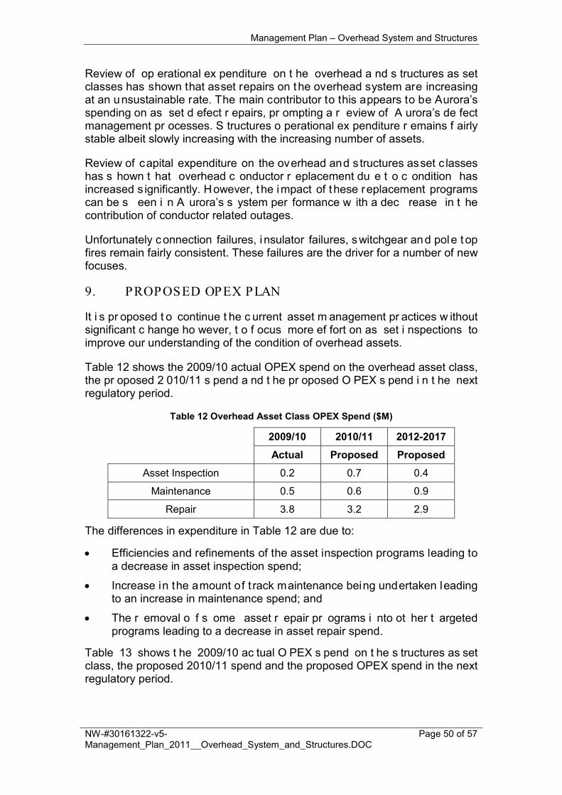
Management Plan – Overhead System and Structures
NW-#30161322-v5-Management_Plan_2011__Overhead_System_and_Structures.DOC
Page 50 of 57
Review of op erational ex penditure on t he overhead a nd s tructures as set classes has shown that asset repairs on the overhead system are increasing at an unsustainable rate. The main contributor to this appears to be Aurora’s spending on as set d efect r epairs, pr ompting a r eview of A urora’s de fect management pr ocesses. S tructures o perational ex penditure r emains f airly stable albeit slowly increasing with the increasing number of assets.
Review of capital expenditure on the overhead and s tructures asset c lasses has s hown t hat overhead c onductor r eplacement du e t o c ondition has increased s ignificantly. However, t he impact of t hese replacement programs can be s een i n A urora’s s ystem per formance w ith a dec rease in t he contribution of conductor related outages.
Unfortunately connection failures, i nsulator failures, switchgear and pole t op fires remain fairly consistent. These failures are the driver for a number of new focuses.
9. PROPOSED OPEX PLAN
It i s pr oposed t o continue t he c urrent asset m anagement pr actices w ithout significant c hange ho wever, t o f ocus more ef fort on as set i nspections to improve our understanding of the condition of overhead assets.
Table 12 shows the 2009/10 actual OPEX spend on the overhead asset class, the pr oposed 2 010/11 s pend a nd t he pr oposed O PEX s pend i n t he next regulatory period.
Table 12 Overhead Asset Class OPEX Spend ($M)
2009/10 2010/11 2012-2017
Actual Proposed Proposed
Asset Inspection 0.2 0.7 0.4
Maintenance 0.5 0.6 0.9
Repair 3.8 3.2 2.9
The differences in expenditure in Table 12 are due to:
• Efficiencies and refinements of the asset inspection programs leading to a decrease in asset inspection spend;
• Increase in the amount of t rack maintenance being undertaken leading to an increase in maintenance spend; and
• The r emoval o f s ome asset r epair pr ograms i nto ot her t argeted programs leading to a decrease in asset repair spend.
Table 13 shows t he 2009/10 ac tual O PEX s pend on t he s tructures as set class, the proposed 2010/11 spend and the proposed OPEX spend in the next regulatory period.

Management Plan – Overhead System and Structures
NW-#30161322-v5-Management_Plan_2011__Overhead_System_and_Structures.DOC
Page 51 of 57
Table 13 Structures Asset Class OPEX Spend ($M)
2009/10 2010/11 2012-2017
Actual Proposed Proposed
Asset Inspection 4.2 3.6 3.8
Maintenance 0.0002 0.02 0.2
The differences in expenditure for the structures asset c lass in Table 13 are due to t he c reation o f new l eaning p ole pr ogram l eading t o a n increase i n maintenance.
10. PROPOSED CAPEX PLAN
Figure 5 below shows the out puts o f a capital ex penditure model f or the overhead s ystem, t aking i nto ac count c ondition, r isk and ag e. T he m odel forecasts capital investment of $480M over the next regulatory per iod, using Aurora’s chosen asset l ives. Using the regulated asset l ife of overhead l ines increased the forecast capital expenditure to $650M.
Aurora’s proposed capital expenditure for the next regulatory period is $70M.
This spend i s s ignificantly l ess than the model f orecast due t o Aurora’s r isk and condition based approach to asset replacement and maintenance, which is targeting specific asset failures as opposed to doing a general replacement.
Capital Expenditure Requirements
0
20
40
60
80
100
120
140
2009 2010 2011 2012 2013 2014 2015 2016 2017 2018 2019 2020 2021 2022 2023 2024 2025 2026 2027 2028 2029 2030
Year
$ m
illio
ns
ReclosersLV FusesHV FusesHV DisconnectorsSectionalisersSWER TransformersTransformersOverhead ServicesLV ConductorABC ConductorAluminium Alloy ConducAluminium ConductorACSR ConductorCopper ConductorSteel Conductor

Management Plan – Overhead System and Structures
NW-#30161322-v5-Management_Plan_2011__Overhead_System_and_Structures.DOC
Page 52 of 57
Figure 5 Overhead System CAPEX Model Output
Table 14 shows t he 2009/10 ac tual C APEX s pend o n t he overhead as set class, t he proposed 2010/11 spend and t he proposed CAPEX spend i n t he next regulatory period.
Table 14 Overhead System CAPEX Spend ($M)
2009/10 2010/11 2012-2017 Actual Proposed Proposed
Conductors - LV (condition) 1.3 1.4 0.9
Conductors - HV (condition) 5.8 3.9 3.2
Conductors - Compliance 2.3 2.7 2.4
OH Switchgear 0.4 0.8 1.3
OH Substations 3.1 3.7 2.4
The differences in expenditure in Table 14 are due to:
• Efficiency i mprovements i n w ork s cheduling and t asks l eading t o a n overall decrease in all CAPEX programs;
• An i ncrease i n t he switchgear program t o address operational and fire start issues with HV EDOs.
Figure 6 below shows the out puts o f a capital ex penditure model f or the structures asset class, taking into account condition, risk and age. The model forecasts capital investment of $290M over the next regulatory period.
Aurora’s proposed capital expenditure for the next regulatory period is $49M.
This spend is less than the model forecast due to Aurora’s risk and condition based approach to asset replacement and maintenance that has shown the number of pole failures in service in not increasing.

Management Plan – Overhead System and Structures
NW-#30161322-v5-Management_Plan_2011__Overhead_System_and_Structures.DOC
Page 53 of 57
Figure 6 Structures CAPEX Model Output
Table 15 shows the 2009/10 actual CAPEX spend on structures, the proposed 2010/11 spend and the proposed CAPEX spend in the next regulatory period.
Table 15 Structures CAPEX Spend ($M)
2009/10 2010/11 2012-2017
Actual Proposed Proposed
Pole replacement 7.8 6.4 7.1
Pole staking 1.7 1.4 1.4
The differences in expenditure in Table 15 are due to a forecast increase in pole replacements due to aging pole population.
11. CAPEX–OPEX TRADE OFFS Structures: Inspection OH - (& treatment) Structures (3.5 year cycle) (OPEX) has a direct impact on R eplace Condemned P ole ( CAPEX) and I nstall p ole s take - Reinforce g round l ine o f uns erviceable pol es ( CAPEX). B y i nspecting t he poles r eplacements can be made bas ed on c ondition an d p reventative treatment can be applied to prolong the life of the poles. Sample inspection and treatment of steel towers (OPEX) and R epair Steel & Concrete Poles (OPEX) have a direct impact on Maintenance OH - Reinforce below ground portion Tower leg (CAPEX). Overhead: Asset inspection o f f eeders i n hi gh f ire d anger ar eas ( OPEX) and A sset Repair - Fire Mitigation (Restrain conductors, install spreaders) (OPEX) have

Management Plan – Overhead System and Structures
NW-#30161322-v5-Management_Plan_2011__Overhead_System_and_Structures.DOC
Page 54 of 57
a di rect impact on Undertake HV and LV overhead conductor fire m itigation works i n v ery hi gh and high fire danger areas ( CAPEX). Inspections ar e performed so work can be undertaken on defects based on priority that have potential to start a fire over the upcoming fire season. B y undertaking asset repairs such as restraining conductors i t defers the capital costs of replacing conductors. Asset R epair O H Switchgear ( OPEX) has a di rect i mpact on R eplace O H Switchgear - Replace sectionaliser - ABB and AK ( CAPEX). By undertaking asset repairs it can defer the capital costs of replacing the switchgear. Maintain OH Switchgear- Reclosers and Fault Indicators (OPEX) has a direct impact o n R eplace N ulec R ecloser & or C ontrol B ox ( CAPEX). B y undertaking m aintenance o n r eclosers a nd f ault i ndicators i t c an de fer t he capital costs of replacing them. Maintain Access Track (OPEX) has a di rect impact on Access Track Create and Rebuild (CAPEX). B y maintaining access t racks i t reduced the need to recreate the tracks for future access. OH T ransformers i nspection & monitoring (earthing) ( OPEX) ha s a di rect impact o n R eplace T ransformer E arths ( CAPEX). T his al lows A urora t o replace transformer earths bas ed on condition rather t han ag e. T his is f or safety and to remove the risk of the unnecessary replacement of earths. Insulator w ashing & pollution m itigation ( OPEX) has a di rect i mpact o n Replace HV Insulators (CAPEX). A lthough the main dr iver behind insulator washing is to prevent pole-top fires, by washing insulators in areas of pollutant build u p i t pr olongs t he l ife of t he i nsulators de ferring t he c apital c ost of replacement. OH s ystem f eeder inspections ( switchgear, c onductor, feeder - aerial and ground) (OPEX) and OH System asset repair (defects) (OPEX) have a di rect impact o n t he following C APEX pr ograms; R eplace H V F eeders ( Safety), Replace LV Fdrs (safety), Replace LV Feeders (Substandard), Replace LV l inks with fuses to address public s afety, R eplace Transformers ( leaking/condition), R eplace Transformers Neutral Replace HV Live Line Clamps (Safety), and Replace all complete EDO at site due to obsolete equipment. By undertaking feeder inspections replacements can be made based on condition and where appropriate repairs can be made on defects to defer the capital costs of replacement.
12. ASSET MANAGEMENT INFORMATION
Aurora m aintains r ecords o f ov erhead as sets t hrough t he p eriodic r outine testing a nd i nspection pr ograms pr oviding t he following i nformation. The equipment details and attributes are predominantly recorded within FRAMME / WASP. These bei ng t he t wo integrated as set m anagement s ystems,

Management Plan – Overhead System and Structures
NW-#30161322-v5-Management_Plan_2011__Overhead_System_and_Structures.DOC
Page 55 of 57
however t here are smaller da ta-sets in MS A ccess a nd E xcel t hat c urrently store other information relating to the asset and its condition.
Recorded information includes:
• Identification number (unique identifier),
• Location / site / geographical details;
• Asset / equipment details (size, make, model, type, rating, installed date;
• Equipment attributes and operational numbering;
• Operational de tails ( connectivity, pr otection and eq uipment s ettings, number of operations - trips, trip and lockouts etc)
• System performance details ( reliability, causes, power quality recorded data etc);
• System monitoring information / data (load – cyclic, maximum demand, load balance);
• Asset condition data and remaining residual life (general and limited);
• Oil condition, contamination levels;
• Age of asset and components, installed / refurbished date;
• Age of related equipment;
• Unit r ates or ag reed costs i .e. i nspection, t reatment r efurbishment and replacement costs;
• Maintenance details / action;
• Maintenance program progress; and,
• Maintenance history (general and limited).
Data t o a nd from t he f ield is m anaged el ectronically enabling frequent updating of the data in our integrated GIS and asset database.
13. RESPONSIBILITIES
Maintenance an d i mplementation of t his m anagement pl an i s t he responsibility of the Thread Leader – Overhead System and Structures.
Approval of this management plan is the responsibility of the Group Manager – Asset Performance and Information.
14. REFERENCES
1. Management Plan 2011: Ground Mounted Substations (NW-#30160765) 2. ENA G uidelines for D esign and M aintenance o f O verhead D istribution
and Transmission Lines (C(b)1) 3. Incospec Needles Tower Line inspection 2006 (NW-10238018) 4. REGMI – Replace GI – Failure Analysis (NW-#30098436)

Management Plan – Overhead System and Structures
NW-#30161322-v5-Management_Plan_2011__Overhead_System_and_Structures.DOC
Page 56 of 57
5. Network P olicy: I nspection a nd M aintenance o f D istribution O verhead Lines (NN R AM 05)
6. Network P rocedure: P ole I nspection a nd Maintenance ( Part 1 – Wood Poles) (NP R AM 27.1)
7. Structures: Annual Equivalent Calculation (NW-# 30103252) 8. Network P olicy: Wood P ole R einstatement by G round-Line
Reinforcement (NN R AM 11) 9. Bushfire M itigation ( Asset P rograms) M anagement P lan
(NW-#30043347) 10. Distribution Protection Review – Hill Michael Report (NW-#30093787) 11. Substandard Conductor Audit Spreadsheet (NW-#30128007) 12. Fire Analysis (NW-#30111032) 13. Structures – Annual Equivalent Calculation (NW-#30103252) 14. AS 3891.1-2008 Air navigation - Cables and their supporting structures -
Marking and s afety r equirements - Permanent marking o f ov erhead cables a nd t heir s upporting s tructures for other t han pl anned l ow-level flying
15. AS 3891.2-2008 Air navigation - Cables and their supporting structures - Marking and safety requirements - Marking of overhead cables for planned low-level flying operations
16. Electrical Transitions Act 1996 17. Electrical Easements Act 2000 18. Occupational Licensing Act 2005 19. The National Greenhouse and Energy Reporting Act 2008 20. EW-M12-01 Disposal of SF6 21. National Environment Protection Management Measure (NEPM) 22. Environmental Management Pollution Control Act 1994 23. EM-M09 Management of PCB’s 24. Australian and New Zealand Environment and Conservation Council
(ANZECC) Polychlorinated Biphenyls Management Plan 25. TAS Environmental Protection & Pollution Act 1994 26. NEPM standards Act 27. AS2067 Substations and high voltage installations exceeding 1 kV a.c. 28. ENA EG-0 Power System Earthing Guide

Management Plan – Overhead System and Structures
NW-#30161322-v5-Management_Plan_2011__Overhead_System_and_Structures.DOC
Page 57 of 57
Appendix A Age P rofiles
A.1 Age of Condemned/Fa iled Poles (from 2000 to 2010)