asset management of roadway signs through advanced ... · pdf fileasset management of roadway...
TRANSCRIPT

Asset Management of Roadway Signs
through Advanced Technology
Kellee Boulais Kruse Tom Simmer
Upper Great Plains Transportation Institute
North Dakota State University
June 2003

Acknowledgements Gary Berreth – NDDOT Director of Operations Richard Parton – NDDOT Grand Forks District, Maintenance Coordinator Steve Arndt – NDDOT Grand Forks District, Highway Traffic Control Supervisor
Disclaimer The contents of this report reflect the view of the authors, who are responsible for the facts and the accuracy of the information presented. This document is disseminated under the sponsorship of the Department of Transportation, University Transportation Centers Program, in the interest of information exchange. The U.S. Government assumes no liability for the contents or us thereof.

i
ABSTRACT
Working together with the North Dakota Department of Transportation (NDDOT), the objective of this project was to develop an application to perform the following:
• Track highway signs with GPS • Keep track of the last date a sign was modified • Manage Sign Inventory • Display this information in a geographical information system
The types of forms automated were chosen based on input from NDDOT. These forms include:
• Sign Maintenance and Installation Record • State Inventory Form • District Inventory Form
The software will run on a handheld computer and a desktop computer. The hardware will include the handheld computer and a portable GPS receiver. The software written for the program will run alongside ESRI ArcGIS geographical information system software.

ii

iii
TABLE OF CONTENTS
CHAPTER 1 1.1 Introduction .................................................................................................................... 1 1.2 Background of the Project ................................................................................................ 2 1.3 Issues with Existing Process ............................................................................................. 2 1.4 Objectives ....................................................................................................................... 3 1.5 Project Phases.................................................................................................................. 4 1.5.1 Phase 1 – Pilot Study ............................................................................................... 4 1.5.2 Phase 2 – Statewide Implementation......................................................................... 4 CHAPTER 2 2.1 Explanation of Automation ............................................................................................... 5 CHAPTER 3 3.1 Software Design ............................................................................................................ 11 3.2 Handheld Software......................................................................................................... 11 3.3 Desktop Software........................................................................................................... 12 CHAPTER 4
4.1 Summary and Conclusions ............................................................................................ 17 4.2 Recommendations .......................................................................................................... 18
REFERENCES.............................................................................................................................. 19

iv
LIST OF TABLES
Table 1.1 Codes Relating to Sign Assembly and Maintenance ..................................................... 3
Table 1.2 Sign Codes in the State Inventory System.................................................................... 3
v
LIST OF FIGURES
Figure 1.1 North Dakota Highway System Portrayed on a GIS Map .............................................. 1
Figure 1.2 North Dakota Department of Transportation (NDDOT) District Boundaries................... 4
Figure 2.1 NDDOT’s Current Sign Inventory Process................................................................... 5
Figure 2.2 Proposed Sign Inventory Process................................................................................. 6
Figure 2.3 State Inventory Form (Handwritten) ............................................................................ 7
Figure 2.4 Sign Maintenance Form.............................................................................................. 8
Figure 2.5 Proposed Workflow after Implementation.................................................................... 9
Figure 3.1 Sign Assemble Form (Handheld) ............................................................................... 11
Figure 3.2 Inventory Form (Handheld) ....................................................................................... 12
Figure 3.3 Desktop Interface..................................................................................................... 13
Figure 3.4 Program Options ...................................................................................................... 14
Figure 3.5 Sign Assemble Form (Electronic) .............................................................................. 15

vi

vii
EXECUTIVE SUMMARY
This research project aims to ease the process of Roadway Sign asset management. The project utilized handheld computer and global positioning system (GPS) technology to capture sign location data along with a timestamp. This data collection effort was designed to replace the handwritten forms used to collect sign information. This technology potentially can reduce the amount of time it takes to collect sign location and inventory data.
Desktop software was developed to process the collected data. Reports are available , which look identical to the handwritten reports. The software records coordinates of the sign, and the road location and other components. These data elements allow managers to determine if signs have not been maintained for extended periods of time. This lets them generate a list of signs that should be replaced or reviewed.
To complete this project continued development should occur. The second phase should contain tasks to integrate the inventory system with the statewide inventory system and provide additional software functions for the users.
Results from this study show that all districts in the NDDOT can benefit from a program that automates the sign inventory process. Data from the program can be used to generate locations of signs and mark signs that need to be examined. This could lead to efficient methods for sign replacement.

viii
1
CHAPTER 1
1.1 Introduction
For many years, states and local jurisdictions, such as cities and counties, have developed manual field systems to monitor and track their street and roadway sign inventories. For most state and local governments current methods are cumbersome and inefficient. Sign inspectors are required to complete an onerous system of paper forms, and then manually enter the forms into a database following an evaluation or inspection.
Although the North Dakota Department of Transportation (NDDOT) currently has an automated database system, which tracks roadway sign inventory, this system only is accessible in the user’s office at his or her desktop computer. While in the field, the user must complete outdated paper forms, and then return to the office to enter information into the inventory system. The sign inventory project uses handheld computers and Global Positioning System (GPS) technology to accomplish the field data collection necessary for the management of roadway sign inventory.
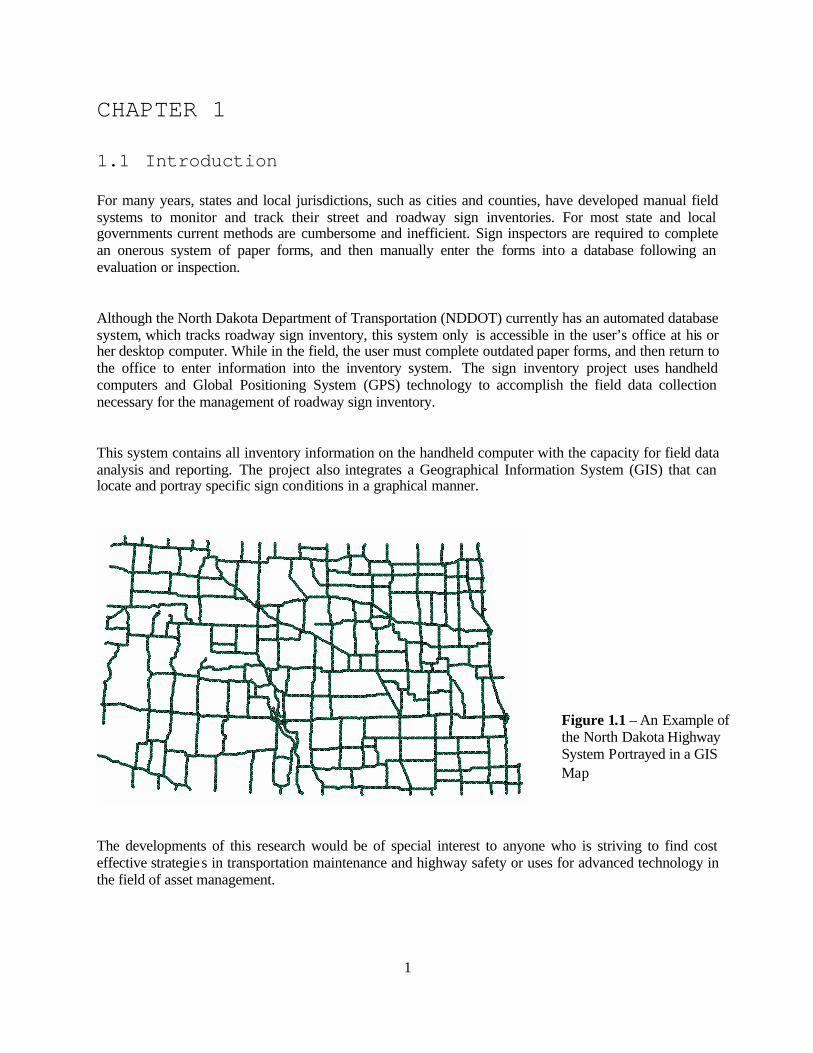
This system contains all inventory information on the handheld computer with the capacity for field data analysis and reporting. The project also integrates a Geographical Information System (GIS) that can locate and portray specific sign conditions in a graphical manner.
The developments of this research would be of special interest to anyone who is striving to find cost effective strategies in transportation maintenance and highway safety or uses for advanced technology in the field of asset management.
Figure 1.1 – An Example of the North Dakota Highway System Portrayed in a GIS Map

2
1.2 Background of the Project
Between June 2001 and December 2002, the Department of Transportation Support Center, a program of the Upper Great Plains Transportation Institute, worked to develop a Maintenance Management Program for the NDDOT. This project contains many of the same aspects of the sign inventory project, such as GPS, GIS, and handheld computers. When this project was presented to the NDDOT, they saw the potential for this technology to be used as a cost effective method for roadway sign data collection and reporting. Looking to increase the efficiency of its field operators, the NDDOT asked the Support Center to develop a new asset management tool.
1.3 Issues with Existing Process
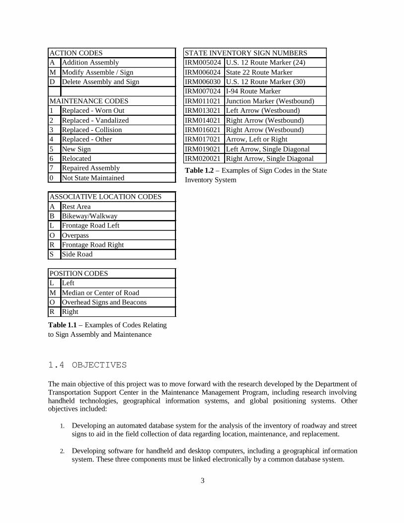
The complaint heard most often regarding the existing system concerned the redundancy of the process. Forms are filled out “in the field ,” then brought back to the office. The data is first entered manually into the district’s own inventory system, then into the state’s centralized system. The employee must report the exact same information three times. Another issue was that certain crucial data was not being recorded and saved. There was no record of the date that a sign had been assembled. This information is an important part of the process of inspection, and without it maintenance is somewhat arbitrary. The third major problem with the current process was the use of codes, which were meaningless to the user. These codes could be embedded in the software, leaving the user with familiar phrases and descriptions.
3
ACTION CODES STATE INVENTORY SIGN NUMBERSA Addition Assembly IRM005024 U.S. 12 Route Marker (24)M Modify Assemble / Sign IRM006024 State 22 Route MarkerD Delete Assembly and Sign IRM006030 U.S. 12 Route Marker (30)
IRM007024 I-94 Route MarkerMAINTENANCE CODES IRM011021 Junction Marker (Westbound)1 Replaced - Worn Out IRM013021 Left Arrow (Westbound)2 Replaced - Vandalized IRM014021 Right Arrow (Westbound)3 Replaced - Collision IRM016021 Right Arrow (Westbound)4 Replaced - Other IRM017021 Arrow, Left or Right5 New Sign IRM019021 Left Arrow, Single Diagonal6 Relocated IRM020021 Right Arrow, Single Diagonal7 Repaired Assembly0 Not State Maintained
ASSOCIATIVE LOCATION CODESA Rest AreaB Bikeway/WalkwayL Frontage Road LeftO OverpassR Frontage Road RightS Side Road
POSITION CODESL LeftM Median or Center of RoadO Overhead Signs and BeaconsR Right
1.4 OBJECTIVES
The main objective of this project was to move forward with the research developed by the Department of Transportation Support Center in the Maintenance Management Program, including research involving handheld technologies, geographical information systems, and global positioning systems. Other objectives included:
1. Developing an automated database system for the analysis of the inventory of roadway and street signs to aid in the field collection of data regarding location, maintenance, and replacement.
2. Developing software for handheld and desktop computers, including a geographical information
system. These three components must be linked electronically by a common database system.
Table 1.1 – Examples of Codes Relating to Sign Assembly and Maintenance
Table 1.2 – Examples of Sign Codes in the State Inventory System

4
3. Improving the capabilities of the N.D. Department of Transportation employees to make decisions regarding roadway sign maintenance and replacement to create a less arbitrary process.
4. Creating reporting tools that can display data in a variety of formats, including web accessible
files. The NDDOT currently is using reports that they wish to continue using, so these must be duplicated by the automated system.
1.5 PROJECT PHASES
1.5.1 Phase 1 - Pilot Study The pilot study was performed with the help of the NDDOT Grand Forks district. The software was built to the specifications of employees who originally requested the project. Each NDDOT district currently uses a different sign inventory process, but no district uses automated field data collection. GPS collection for sign locations also is not collected by any individual NDDOT district office. 1.5.2 Phase 2 – Statewide Implementation Pending the approval of NDDOT upper management, the sign inventory system will be implemented in each of the eight district offices statewide. This will bring uniformity to the NDDOT’s sign inventory process. Each district database will link to a system in the NDDOT central office in Bismarck, N.D. Establishing this link requires full cooperation of the NDDOT’s Information Technology department, and even the Grand Forks district may have to wait until Phase 2 to make this connection.

5
Figure 1.2 – This map illustrates the NDDOT district boundaries. This project was tested in the northeastern Grand Forks district. (Source: http://www.state.nd.us/dot/)

6
CHAPTER 2
1.1 EXPLANATION OF AUTOMATION
The main focus of this research project was to automate the sign inventory process, making it easier and more efficient to collect and enter data. Focus was put on eliminating redundant steps in data entry and adding functionality to the process. With the handheld computer and GPS receiver, it would be possible to integrate geographical coordinates into the sign inventory process. GPS would allow for sign data storage and retrieval based on the location of the sign. Currently the sign inventory process involves filling out redundant forms and re-entering data after it is collected in the field. The forms are filled out and brought back to the district office where the data is re-entered into the state inventory system and into the district’s own inventory system.
Figure 2.1 – An Illustration of the NDDOT’s Current Sign Inventory Process

7
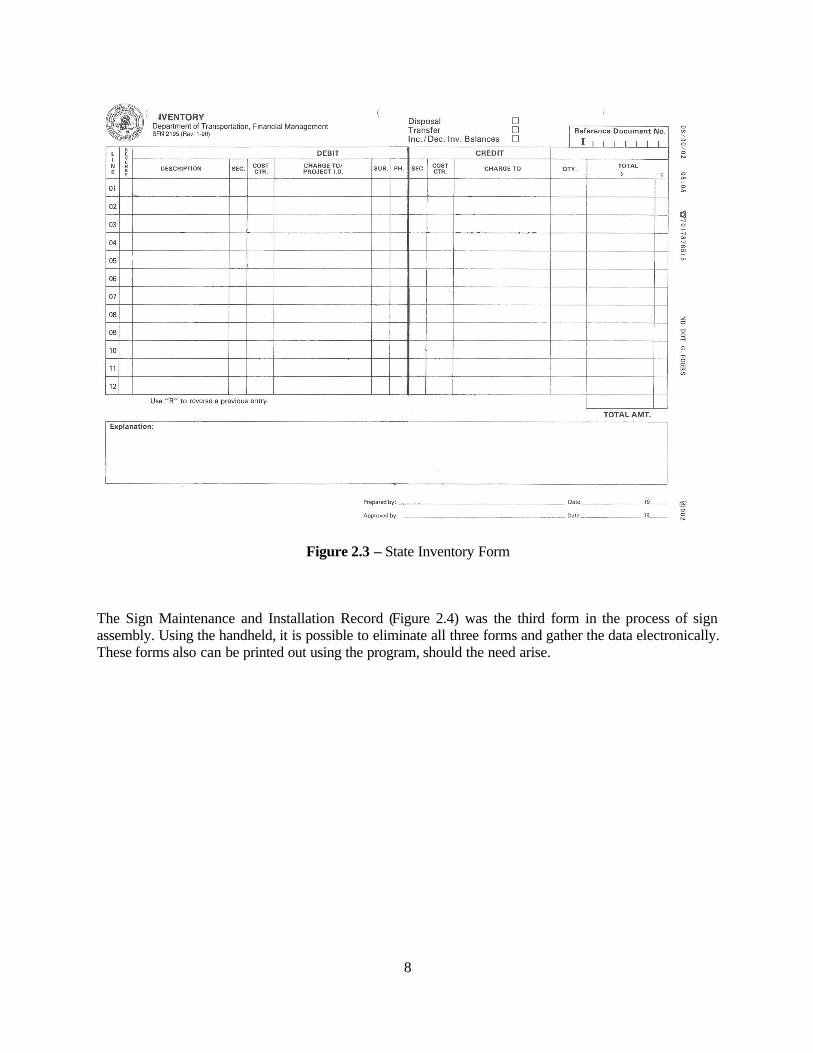
Three main forms were used in the inventory process. Two were filled out in the field and one was filled out at the office from information already entered on one form. Separate state and district inventory forms were filled out and were similar. Figure 2.2 is a copy of the district inventory form, while figure 2.3 is a copy of the state inventory form. Similarities between the inventory forms make it possible to gather the data only once from the handheld and produce both forms from the data. The third form is the Sign Maintenance and Installation Record form, this form is filled out each time a sign is put up, maintained, or removed from the roadside.
Figure 2.2 – District Inventory Form
8
Figure 2.3 – State Inventory Form
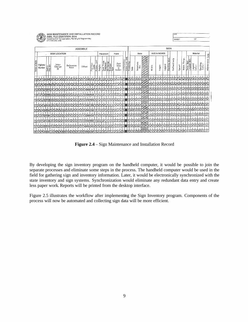
The Sign Maintenance and Installation Record (Figure 2.4) was the third form in the process of sign assembly. Using the handheld, it is possible to eliminate all three forms and gather the data electronically. These forms also can be printed out using the program, should the need arise.
9
Figure 2.4 – Sign Maintenance and Installation Record
By developing the sign inventory program on the handheld computer, it would be possible to join the separate processes and eliminate some steps in the process. The handheld computer would be used in the field for gathering sign and inventory information. Later, it would be electronically synchronized with the state inventory and sign systems. Synchronization would eliminate any redundant data entry and create less paper work. Reports will be printed from the desktop interface. Figure 2.5 illustrates the workflow after implementing the Sign Inventory program. Components of the process will now be automated and collecting sign data will be more efficient.

10
PDA SignMaintenance& Inventory
Form
DistrictInventory
RIMS
DistrictInventory
StateInventory
Workflow AfterProposed
Implementation
Figure 2.5 – An Illustration of the Inventory Process Proposed in this Research
As Figure 2.5 illustrates, filling out the manual forms will no longer be necessary, and the manual entry of data to the inventory systems will not occur. Inventories will be updated automatically and the handheld computer will contain the most current inventory data. The workflow is simpler and there are far fewer steps involved in the process. By synchronizing the handheld each day, all data formerly filled out on forms is transferred to the database with the press of a button. The desktop interface also will allow for users to update the inventory and add new items to the database. This allows for future expansion and scalability across all state districts. With slight modification and customization the program can be adapted to fit the needs of anyone working with signs or location specific inventory. By using the desktop interface the users can make sure the most up-to-date information is available to users in the field.

11

12
CHAPTER 3
3.1 Software Design
The Sign Inventory was designed with several uses in mind. The data collection component was written in Microsoft eMbedded Visual Basic for use on the IPAQ handheld device. The purpose of this component was to collect data on sign location using GPS (Global Positioning System), maintenance performed, as well as maintenance history, and sign age. The desktop component of the software was designed in Microsoft Access and provides the user with data manipulation tools , reports and other analysis tools. The desktop component is tied to the handheld component so that data collected on the handheld can be synchronized with the desktop database. The software also uses ESRI’s ArcGIS to illustrate locations of the signs on a state map. This software allows for the tracking of signs and their locations. This can be beneficial for planning maintenance routes and inventory management. 3.2 Handheld Software
The handheld portion of the Sign Maintenance software is designed to run on an IPAQ device with a NAVMAN GPS receiver. The software primarily is used for data gathering for signs and inventory management. There are two main pages for input on the program: a Sign Assemble form and an Inventory form. The Sign Assemble form was designed to collect data about the placement and type of the sign, what parts were used; the GPS location of the sign, and the date it was installed or maintenance was performed. The form appears below.
Figure 3.1 – Sign Assemble Form

13
The Inventory form was designed to replace two previous forms (discussed in Chapter 2). The inventory number, description, section, and other information were collected to help automate the inventory update process. The Inventory Form stored inventory updates in a database and when synchronization was performed the desktop database was updated with the inventory. Eventually this inventory system will tie into the state Department of Transportation inventory to automatically update. The Inventory form is shown below. Dropdown menus were used for both forms to account for the difficulty of entering data manually on the handheld.
Figure 3.2 – Inventory Form
This form is used to replace two handwritten forms that had been filled out redundantly. One form was for the district and the other was for the state, both forms contained similar information. The Inventory from on the handheld collects data formerly collected on the two handwritten forms. The desktop software allows the user to print out both forms if necessary.
3.3 Desktop Software
The desktop software is designed to be an interface where the user can customize the data in the database and print out sign inventory or assemble reports. This component also interfaces with the ESRI’s ArcGIS providing a visual representation of where the signs are located. Inventory and sign part numbers can be modified from forms in the desktop software. An example of the desktop software is shown below. Desktop menus and forms can be used to maintain and update the program. Updating the tables corresponding to the handheld allows for immediate updating of inventory, sign types and other information.

14
Figure 3.3 – Desktop Interface
The Export GPS button creates a file that can be imported into ArcInfo and also launches ArcInfo. Reports that appear similar to the original manually filled forms can be printed by clicking Print Inventory or Sign Reports. Add/Remove Items is used to modify the different information in the database.

15
Figure 3.4 – Program Maintenance Options
The menu shown in Figure 3.4 is used to modify the existing data in the program in the event that new inventory items arrive or new signs need to be added to the database.
Figure 3.5 is an example of the Sign Assemble report generated by the Desktop Interface. This form is generated based on the data entered by the user and is comprised of all records entered on that date.

16
Figure 3.5 – Electronic Sign Assemble Form
This form has been designed to be a replica of the actual form currently used in the sign inventory process. The original form is shown in Chapter 2, Figure 2.4. The handheld and desktop components work together to create a completely electronic process for taking sign inventory. Customization and modification allow for the program to continue evolving to meet the users’ needs.

17

18
CHAPTER 4
4.1 Summary and Conclusions
Although the N.D. Department of Transportation seems to understand the importance of automating and improving its roadway sign inventory process, it has not taken any steps in this direction. Reasons for this shortage of automation include a lack of computer programmers and technical resources. The employees who suggested automating the process of sign inventory have been requesting these changes for many years. The requested changes could improve working conditions for employees in all eight NDDOT districts. A common complaint regarding the NDDOT’s sign inventory process is that much of the data that is to be gathered is not used by anyone, either in the central office or in the districts. The employees collecting data commented that they often leave several fields blank on their inventory forms because gathering this information is not necessary or practical. It becomes even less convenient when you consider that the employee must enter this information more than once. In addition to collecting unnecessary and redundant information, these forms contain several cryptic codes. The employee collecting the inventory data must carry manuals with them in the field to decipher these codes and use them correctly. On the other hand, some employees think that other pieces of information should be collected and currently are not part of the sign inventory process. Dates regarding the assembly or maintenance of the sign are important to the inspection process. Signs are to be inspected on regular intervals, and without these dates employees are inspecting the signs on a much more random basis. These inspections basically take place anytime an employee is in the vicinity of a sign, which may leave problems with signs undetected if the sign is located in a remote area. This project was an excellent way to use the lessons learned in the Maintenance Management Project. The handheld GPS receivers used in the Maintenance Management Project were the same ones used in the Sign Inventory Project. This study concludes that it is possible to automate and simplify the sign inventory process for the N.D. Department of Transportation. The process can be made more efficient and the data collected can be more useful. Because much of the work has been completed in the process of this study, only a small commitment is required by the NDDOT to implement the system. Changes and customizations could be done according to their specifications if they are willing to provide the necessary funding.

19
4.2 Recommendations
There are many recommendations from this study that the NDDOT could use to improve their sign inventory process.
1. Implement the proposed sign inventory process in all eight NDDOT districts. The software
will be provided for free. Purchasing hardware will be the responsibility of the NDDOT. Changes to the software will be provided by the Department of Transportation Support Center for a fee, or the NDDOT can choose to make changes themselves.
2. Allow the new system to feed into the centralized inventory system in Bismarck, allowing
users to enter data only once.
3. Increase budget to include ESRI’s ArcINFO software in all district offices. The lack of
ArcINFO licenses makes it difficult for the NDDOT to use GIS to its fullest potential. 4. Interview the employees involved in the sign inventory process to determine the following
items:
a. Is the inventory data that they are requiring necessary? b. Is this data used by the central office or the districts? c. Could the system of coding be improved to make it easier for employees to use? d. Are there some data items not required in the inventory system that should be
included?
5. Continue to look for processes to automate and improve. The Upper Great Plains Transportation Institute has many resources and programs that can be of help in the research and implementation of process automation. A willingness on the part of management to outsource this research will be needed on the part of management, especially the management of the NDDOT’s Information Technology Department.
Further design and testing will help to add total functionality to the program. The next step is synchronizing the database with the state database system. This involves creating an interface between the two. After this is accomplished the project can completely replace the old method. Currently the Sign Inventory program can greatly ease the burden of data collection and entry. A program such as this can easily be transferred from district to district so that an organization like the NDDOT can adapt it to specific areas. Finally, this process is much more efficient than the old method and should make Sign Inventory less time consuming after the initial learning curve.
20
REFERENCES 1. Leveraging Technology Investments Integration of GPS, GIS, and Maintenance Management,
Mountain-Plains Consortium, Fargo, ND, 2003. 2. Directions Magazine Online, GIS Tools, Glencoe, IL, April 22, 2002,
http://www.directionsmag.com/tools/.
3. ESRI – The GIS Software Leader, Environmental Systems Research Institute, Inc, http://www.esri.com/.
4. North Dakota GIS (Geographical Information Systems) Home Page, (2003) North Dakota
Information Technology Department, http://www.state.nd.us/gis/.