associated 1:10 scale t3 manual - … 1:10 scale t3 manual instruction manual for the rc10t3...
TRANSCRIPT

ASSOCIATED 1:10 SCALE T3 MANUALASSOCIATED 1:10 SCALE T3 MANUAL
INSTRUCTION MANUAL FOR THERC10T3 ELECTRIC TRUCKS#7003, 7013, 7038, 7048
ASSOCIATED’S RC10T3 TRUCK--READER’S CHOICE OF THE YEAR TIMES!Radio Control Car Action magazine, July 2000, May 1999, May 1998
©2000 Associated Electrics, Inc.

TEAM KIT SPORT KIT BASIC KITShocks: Hard anodized, PTFE-
coated gray.
Rear Axles: MIP CVD's.
Also includes: Sealed ball
bearings.
Shocks: Gold shocks.
Rear Axles: Associated dogbones &
stub axles.
Also includes: Mechanical speed
control and motor. Bushings
throughout.
Shocks: Gold shocks.
Rear Axles: Associated dogbones &
stub axles.
Also includes: Bushings
throughout.
FACTORY TEAMShocks: Hard anodized, PTFE-
coated gray.
Rear Axles: MIP CVD's.
Also includes: Factory Team
parts, graphite chassis, sealed ball
bearings.
2
YOU WILL NEED THESE TOOLSTO ASSEMBLE YOUR KIT
Phillips screwdriver #2.1/8" flat head screwdriver.5/16" driver or glow plug wrench.Needlenose pliers.Super glue (cyanoacrylic glue).Hobby knife WARNING! This knife cuts plastic and fingers with equal ease, so be careful.Precision ruler.Team Associated Locking Adhesive (#1596)
WARNING! Always use hand and eye protection with cyanoacrylic glue!
REQUIRED EQUIPMENT TO RUN YOUR KIT
TOOLS SUPPLIEDAllen wrenches, .050", 1/16", 3/32", 5/64".
Molded tools (#6956):
HELPFUL TOOLS (NOT REQUIRED)Allen drivers (straight Allen wrenches with hex shaped handles) such as the following made by Associated:#6957 .050" Allen wrench#6958 1/16" Allen wrench#6959 5/64" Allen wrench#6960 3/32" Allen wrench#6961 2.5mm Allen wrenchHand drill with 1/8" & 1/4" bitsVernier calipersHobby scissorsLiquid dish soapNut drivers (screwdriver-handled hex socket tools) such as the following from Associated:#SP-86 3/16" nut driver#SP-85 1/4" nut driver
WARNING! Do not use a power screwdriver to install screws into nylon, plastic, or composite materials. The fast rotation speed can heat up the screws being installed. They can then break the molded parts or strip the threads during installation.
All kit versions include:2.40:1 transmission for effortless power handling.Lexan T3 racing body.Quadra-symmetric suspension for greater stability and handling.Optimized front end geometry improves steerging and increases rigidity.Adjustable battery placement for fine tuning of traction or steering.2.2" one-piece front and rear wheels.Pro-Line Edge M2 front tires and Pro-Line "Bowtie" M2 rear tires.
for the T3 Basic+ kit #7003
R/C two channel surface frequency radio systemwith one servo.Battery pack (6 cell).Battery charger (we recommenda peak detection charger).Electronic speed control.Pinion gear, 48 ptich. Teeth to be determined by type and wind ofmotor.
for the T3 Sport kit #7013
R/C two channel surface frequency radio systemwith two servos.Battery pack (6 cell).Battery charger (we recommenda peak detection charger).
for the T3 Team kit #7038
R/C two channel surface frequency radio systemwith one servo.Battery pack (6 cell).Battery charger (we recommenda peak detection charger).Electronic speed control.R/C electric motor. Pinion gear, 48 ptich. Teeth to be determined by type and wind ofmotor.
for the Factory Team kit #7048
R/C two channel surface frequency radio systemwith one servo.Battery pack (6 cell).Battery charger (we recommenda peak detection charger).Electronic speed control.R/C electric motor. Pinion gear, 48 ptich. Teeth to be determined by type and wind ofmotor.
BEARING KITS BUSHING KITS
Pro-Line body in Team and Factory Team kits shown.

7211
step 1
ASSEMBLE STEERING BLOCKSAssemble parts #7220, 6466, 6273 and 6272. Push #7221 (7221B*) axle into the #7220 steering block, lining up holes. Push the #7211 kingpin through both to clear any burrs. Then remove the kingpin.
ASSEMBLE BLOCK CARRIERSNote location of L and R on #7210 block carriers and #7220 steering blocks.Align holes of #7220 (L) inside #7210 (L). Add one #4187 spacer to #7211 kingpin and insert #7211 through block and axle. Add a #6272 dust cover to the ball end as shown.Insert one #4187 spacer and then one #6299 E-clip to the bottom of #7211 kingpin.Add screw locking compound such as #1596 Factory Team Locking Adhesive® (not included in kit) to #6951 set screw and tighten into #7221 (7221B*).Now assemble right side.
LEFT SIDE
7210
6273
6299
"L" = left side"R" = right side
BAG AREMOVE THESE PARTS FOR:
Step 1
.050
7221, 7221B*
6272(foam)
3
TOOLS USED
Match this numberto the text to findyour way faster
Align this hole with hole in #7220
7220
6951
6272(foam)
4187
4187
"L" = left side"R" = right side
ASSOCIATED ELECTRICS, INC.3585 Cadillac Ave.Costa Mesa, CA 92626-1401USAhttp://www.rc10.com http://www.teamassociated.com
CUSTOMER SUPPORT(714) 850-9342Fax (714) 850-1744http://www.rc10.com/helphttp://www.rc10.com/kits
READ THIS BEFORE BUILDINGREAD THE MANUAL!This manual is for several different T3 kits and will help you assemble and set up each one. Read the manual before starting your kit and before contacting us for help. "Hello, Associated, I need some help." "Did you read the manual?"
OPEN THE BAGS IN ORDERThe assembly is arranged so that you will open and finish that bag before you go on to the next bag. Sometimes you will have parts remaining at the end of a bag. These will become part of the next bag. Some bags may have a large amount of small parts. To make it easier to find the parts, we recommend using a partitioned paper plate for spreading out the parts so they will be easier to find.
SUPPLEMENTAL SHEETS
We are constantly updating parts to improve our kits. These changes, if any, will be noted in supplementary sheets located in a parts bag or inside the kit box. Check the kit box before you start and each bag as it is opened. When a supplement is found, attach it to the appropriate section of the manual.
MANUAL FORMAT The following explains the format of these instructions. The beginning of each section indicates:1 Which bag to open ("BAG A") and which steps you'll be using those parts for ("FOR STEPS 1-3").2 Which parts you will use for those steps. Remove only the parts shown. "1:1" indicates an actual size drawing; place your part on top and compare it so it does not get confused with a similar part.3 Which tools you should have handy for that section.4 An asterix ( * ) next to a part number indicates the part used in the Factory Team T3 kit. (You can use those numbers to upgrade your T3 kits to Factory Team specs.)5 The instructions in each step are ordered in the order you complete them, so read the words AND follow the pictures. The numbers in circles are also in the drawing to help you locate them faster.6 When we refer to left and right sides of the truck, we are referring to the driver's point of view inside the truck.
8
Asterix ( * ) denotes Factory Team part number.Use this number if you have the Factory Team kit.
©2000 Associated Electrics, Inc.
RACER'S NOTE: When using optional 25 deg. block carriers, remove this spacer.
6466
6273, qty 2ball end
7210, qty 2front block carrier,30° caster
6272, qty 4dust cover
7220, qty 2front steering block
6951, qty 24-40 set screw
6299, qty 2E-clip
1:11:11:1 1:1
7221, 7221B*, qty 2front axle
7211, qty 2kingpin ball end
4187, qty 41/32" thin plasticwasher
1:1

ball cups thread on in opposite directions 1:1
REMOVING BALL CUPSHold the cup next to the ball with your pliers and twist the cup off.
7213, 7214*, qty 1front shock tower
REMOVE SUSPENSION ARMSTwist the #7205 (7204*) suspension arms from the mold runners (shown in black) with your pliers, and trim away remainingmolding with your hobby knife.Place the #7223 (7204*) front shock mount on the front arm, the taller end of the mount toward the outside of the arm, and secure using two #6922 (6938*) screws.
ARMS TO BULKHEADAttach the block carrier assembly to the #7205 (7204*) suspension arm with its #9115 hinge pin and #6299 E-clips.Align the #9125 bulkhead with the suspension arm hinge pin holes as shown. Install #6299 E-clip to one end of #9110 hinge pin. Next hold the #9120 front cross brace in front of the suspension arm while sliding the #9110 hinge pin through the assembly. Install #6299 E-clip to other end of pin. Assemble the other side the same way.
SHOCK TOWER TO BULKHEADAttach the shock screws and hardware #7413, 6936 and 6295. Do other side.Attach the #9145 black ball ends and #7260 nuts.Attach the #7213 (7214*) shock tower to the #9125 bulkhead with the three #6924 screws.Twist #7230 ball cups onto the #7253 (1408*) turnbuckle until you get the dimension shown.Add #6272 foam to the ball ends. Connect ball ends with the turnbuckle #7230 ball cups as shown, using your needlenose pliers.
7413, qty 24-40 x 3/4
6936, qty 2#4 washer
6295, qty 24-40 nut
6924, qty 34-40 x 3/8
9145, qty 2ball end
7230, qty 4large ball cup
7253, 1408*, qty 2turnbuckle
9110, qty 2front inner hinge pin
9115, qty 2front outer hinge pin
6299, qty 8E-clip
9120, qty 1cross bracesteel
9125, qty 1front bulkhead
step 2LEFT SIDE
BAG A7260, qty 24-40 nut
3/32", 1/16"
1:11:1 1:11:1
1:1
1:11:1
1:1 1:1 1:1
1:1
TOOLS USED
COMPLETED FRONT ASSEMBLY
4
7205, 7204*, qty 2front suspension arm
VIEWED FROM REAR
REMOVE THESE PARTS FOR:
Step 2
7205, 7204*
9115
9125
9145
9120
6295
6936
6924
7230
9110
6299
7260
7413
7205, 7204*
HOW TO USE THETURNBUCKLE WRENCH
3 13/32" (3.40" or 86.4mm)
7253, 1408*
7253, 1408*
7223, 7204*
9
7205, 7204*
7223, 7204*, qty 2front shock mount
1:1
6922, 6938* qty 44-40 x 1/2
6922,6938*
6299
6299
6299
7230
7413
7260
6272
62729
9
9
7213, 7214*

KICKUP TO CHASSISAdd screw locking compound such as #1596 Factory Team Locking Adhesive (not included in kit) to the three #9215 screws and attach the #9210 (9210B*) aluminum kickup (nose plate) to the #7308 (7309*) chassis.Place the two #9160 servo saver/bell crank mounting pins in the locating holes.
9215, qty 36-32 x 3/16
step 1
9160, qty 1mounting pin,right hand
9160, qty 1mounting pin,left hand
SERVO SAVERPush one #9155 servo saver bushing into each end of the #9158 (9156B*) aluminum tube.Slide the two #9155 servo saver arms onto the tube.Slide the #9157 spring and #9158 (9156B*) adjusting nut on the tube. Tighten the nut until 1/32" of the tube threads are exposed.Add three #6270 ball ends where shown and three #6272 foam dust covers onto them.
BELLCRANKInstall the two #9155 bushings (or 9162* bearings) into the #9155 bell crank.Add two #6270 ball ends where shown and two #6272 foam dust covers onto them.
6270, qty 5ball end
6272, qty 5dust cover
9155, qty 2left hand servo saver bushing
9155, qty 1servo saver arm
9155, qty 1servo saverarm
9158, 9156B*, qty 1tube,aluminum
9158, 9156B*, qty 1adjusting nut
9157, qty 1servo saverspring
9155, qty 1bell crank
9165, qty 1drag link
DRAG LINKInstall the #9165 drag link over the two ball ends with your needlenose pliers.
1:1 1:1
1:1 1:1 1:11:1
1:1
9210, 9210B*, qty 1kickup
TOOLS USED
step 2
5
step 3
REMOVE THESE PARTS FOR:
Steps 1-3
9210,9210B*
9160
9215
9160
9215 9215
6272
6272
6272
9155
9155
9158, 9156B*
9155
9155
9155,9162*
9155, 9162*
9155
6270
62706270
6270
9158, 9156B*
9157
6272
9165
BAG B
9162*, qty 2ball bearing OR9155, qty 2bushing
1:1
7308,7309*
RC Car Action magazine'sReader's Choice Award
RC Car Action's Truck of the Year Award
Top Ten Reader's Choice AwardRC Car Action magazine
RC Car Action magazine'sReader's Choice Award

SERVO SAVER TO CHASSISPlace the servo saver assembly over the pins.
TOP PLATE TO CHASSISLine up the #9130 (9131*) front top plate with the servo saver pins and screw holes.Bolt down the top plate with two #6923 screws tightly, then back off both screws one full turn. This will allow us to accomplish step 5.
6292, qty 24-40 x 3/8
BAG B
9130, 9131*, qty 1front top plate
6923, qty 24-40 x 3/4
9220, qty 1front bumper
7673, 6933*, qty 24-40 x 5/16
1:1 1:1 1:1
FRONT END TO CHASSISSlip front end under top plate, then push rearward over kickup.
TOOLS USED
step 4
1/16"
step 5
6
step 6
REMOVE THESE PARTS FOR:
Steps 4-7
9130, 9131*
6923
under top plate
over kickup
6923
BUMPER TO CHASSISAdd two #6292 screws to secure the front end assembly to the front kickup.Go back and tighten the two #6923 screws from Bag B in step 4.Bolt on the #9220 bumper with the two #7673 (6933*) screws.
7673, 6933*
6292
7673, 6933*
9220
6292
2
step 7
BODY MOUNT TO CHASSISSecure the #7321 front body mount to the top plate with two #6918 screws.
7321
6918
1:1
6918, qty 24-40 x 1/2
7321, qty 1front body mount

7253, 1408*, qty 22.62" turnbuckle
7230, qty 4large ball cup
1:1 1:1
TURNBUCKLESAdd #7230 ball cups to two #7253 or 1408* turnbuckles to the dimension shown.Pop on the turnbuckles with your needlenose pliers. Do both sides.
TOOLS USED
step 8
7
REMOVE THESE PARTS FOR:
Step 8
ball cups thread on in opposite directions
3 3/8" (3.37" or 85.7mm)
7230 72307253, 1408*
1:1
behind the scenes
DUANE SILVA STEVE HUSTING MIKE OGLEDuane writes the text and creates the computer models and images for the manual. He coordinates the manual and catalog and makes sure nothing gets left out.
Steve is responsible for the overall layout, design and production of the manual. He works closely with Duane to integrate all elements into the manual.
MRO is our resident photographer. He shoots the actual model stills, including the exciting action shot used for the manual and catalog covers, and box art.

TRIM SUSPENSION ARMSTwist the #7340 (7339*) suspension arms from the mold runners (shown in black) with your pliers, and trim away the remaining molding with your hobby knife.
step 2LEFT SIDE
REAR PLATE TO CHASSISAttach the two #9267 (3-3) rear suspension arm mounts to the #9241 (9241B*) chassis plate with two #9269 5-40 x 1/2 screws and a single #6936 washer as shown. These mounts are marked L3-3 (left) and R3-3 (right). The coding stands for 3° toe in and 3° anti-squat. NOTE: by using the #4 washer, your anti-squat is effectively reduced to 1.5°.Fasten the chassis plate to the bottom of the chassis with four #6292 screws.Add two #6273 ball ends to the inside holes of the chassis, then thread on the #7260 nuts to the ball ends. Then add the #6272 foam dust covers.
SUSPENSION ARMS TO MOUNTSAttach the #7341 (7339*) left shock mount to the #7340 (7339*) left suspension arm with two #6917 (6860*) screws. Both mount and arm are labeled "L".
Attach the #7340 (7339*) left suspension arm to the #9267 left mount with the #9260 hinge pin and #6299 E-clips.
Now do the right side.
step 1
8
step 3LEFT SIDE
7340, 7339*, qty prrear suspension arm
9267, qty 2rear suspension mount, 3-3(3° toe-in, 3° anti-squat)
9260, qty 2rear inner hinge pin
9241, 9241B*, qty 1rear chassis plate
7260, qty 24-40 nut
6272, qty 2dust cover
1:1 1:1 1:1
6273, qty 2ball end
1:1
6299, qty 4E-clip
1:1
9269, qty 45-40 x 1/2
1:1
6292, qty 44-40 x 3/8
1:1 TOOLS USED
1/16", 5/64"
1:1
6936, qty 2#4 washer
REMOVE THESE PARTS FOR:
Steps 1-3
7341, 7339*
Make sure the arm's outer rib is facing down
7340, 7339*
BAG C
3
7340, 7339*
9267
9269 9269
6936
6292
6292
62926292
62736272
7260
6273
6272
7340, 7339*
6917,6860*
9267
9260
6299
6299
7341, 7339*qty prrear shock mount
1:1
6917, 6860*, qty 44-40 x 3/8
9241, 9241B*
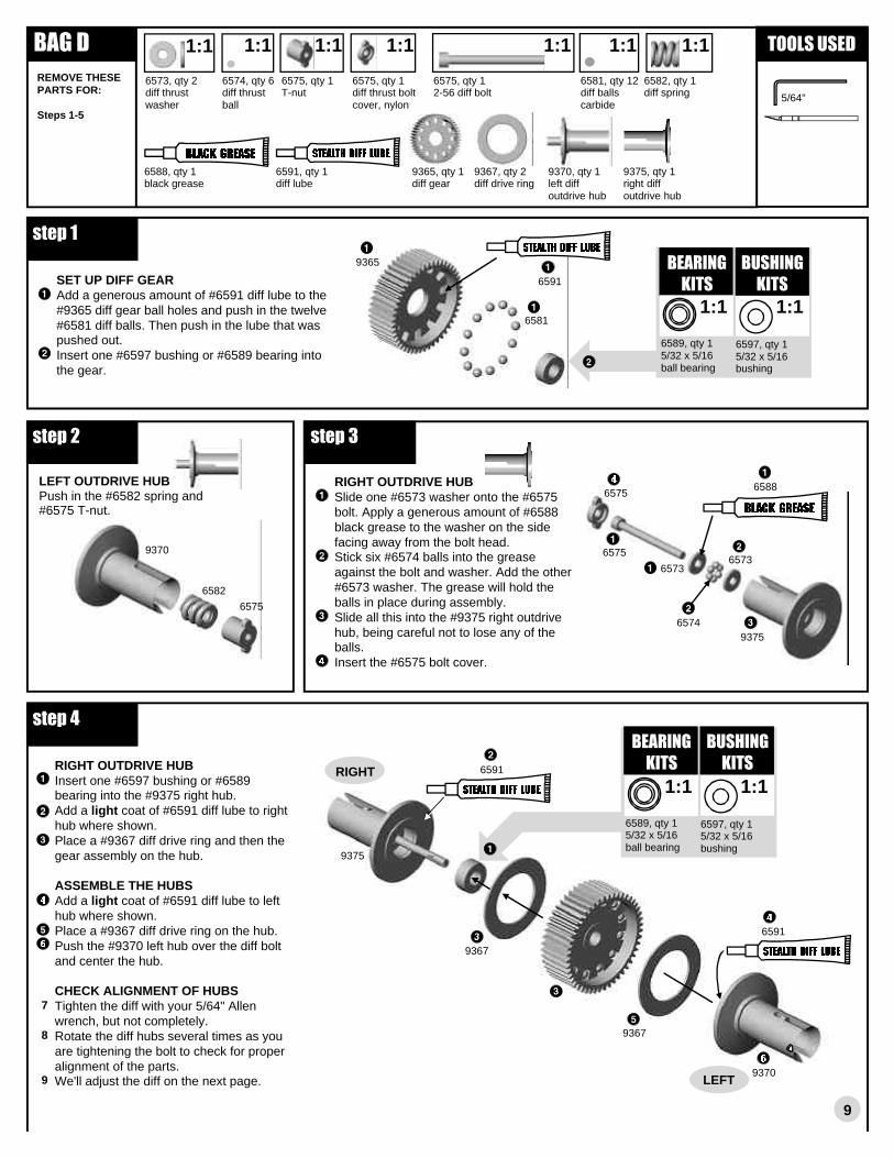
SET UP DIFF GEARAdd a generous amount of #6591 diff lube to the #9365 diff gear ball holes and push in the twelve #6581 diff balls. Then push in the lube that was pushed out.Insert one #6597 bushing or #6589 bearing into the gear.
BAG D
9365, qty 1diff gear
1:1
6581, qty 12diff ballscarbide
6591, qty 1diff lube
6597, qty 15/32 x 5/16bushing
BEARINGKITS
1:1
9365
65811:1
6589, qty 15/32 x 5/16ball bearing
LEFT OUTDRIVE HUBPush in the #6582 spring and #6575 T-nut.
9370, qty 1left diffoutdrive hub
6582, qty 1diff spring
6575, qty 1T-nut
6573, qty 2diff thrustwasher
6574, qty 6diff thrustball
6575, qty 12-56 diff bolt
9375, qty 1right diffoutdrive hub
6575, qty 1diff thrust boltcover, nylon
9367, qty 2diff drive ring
6582
9367
9370
6573
6575
6588, qty 1black grease
6574
6573
9375
6575
1:1
RIGHT OUTDRIVE HUBInsert one #6597 bushing or #6589 bearing into the #9375 right hub.Add a light coat of #6591 diff lube to right hub where shown.Place a #9367 diff drive ring and then the gear assembly on the hub.
ASSEMBLE THE HUBSAdd a light coat of #6591 diff lube to left hub where shown.Place a #9367 diff drive ring on the hub.Push the #9370 left hub over the diff bolt and center the hub.
CHECK ALIGNMENT OF HUBSTighten the diff with your 5/64" Allen wrench, but not completely.Rotate the diff hubs several times as you are tightening the bolt to check for proper alignment of the parts. We'll adjust the diff on the next page.
9367
9375
9370
6597, qty 15/32 x 5/16bushing
1:1 1:1
6589, qty 15/32 x 5/16ball bearing
1:1 1:1 1:1 1:1 1:1 TOOLS USED
step 1
9
5/64"
step 2 step 3
6575
6588
6591
6591
step 4
RIGHT
LEFT
REMOVE THESE PARTS FOR:
Steps 1-5
6591
RIGHT OUTDRIVE HUBSlide one #6573 washer onto the #6575 bolt. Apply a generous amount of #6588 black grease to the washer on the side facing away from the bolt head.Stick six #6574 balls into the grease against the bolt and washer. Add the other #6573 washer. The grease will hold the balls in place during assembly.Slide all this into the #9375 right outdrive hub, being careful not to lose any of the balls.Insert the #6575 bolt cover.
7
8
9
BUSHINGKITS
BEARINGKITS
BUSHINGKITS

BAG D
9352, qty 1right tranny case
9352, qty 1left tranny case
3976, qty 23/8 x 5/8unflanged bearing
3977, qty 23/16 x 3/8unflanged bearing
6598, qty 23/8 x 5/8bushing
6599, qty 23/16 x 3/8bushing
1:1
6571, qty 1 top shaft/gear
7669, qty 2 top shaftspacer
9360, qty 1 idler gear
ADD BUSHINGS OR BEARINGS TO THE CASE HALVESCut the two #9352 transmission case halves and the three #9352 spacers from the runner.Add bushings or bearings to each case half.
1:1
9361, qty 1 idler gear shaft
6928, 6935*, qty 34-40 x 1
6572, qty 1drive shaftroll pin
6292, 6934*, qty 14-40 x 3/8
1:1 1:1 1:1
1:1
1:1
ADJUST THE DIFFERENTIAL As you tighten the diff bolt, you will notice the T-nut ears moving closer to the bottom of the diff hub slot. This compresses the spring behind the T-nut. The spring should be fully compressed at the same time the T-nut reaches the end of the slot. Caution: Pay close attention to feeling when
the spring is fully compressed. Do not overtighten the bolt. When you feel the spring fully compressed, loosen the diff bolt 1/8 of a turn. No more, no less. Your diff should now operate very smoothly when turning the hubs in opposite directions. After you have driven the car once, recheck the diff adjustment. Never adjust the diff any other way.
INSIDE THE TRANNYInstall the right side diff assembly into the right case. (Insert the side that has the diff bolt head showing.)Add the #7669 spacer to the #6571 drive shaft and put both into the right case.Install the two bushings or bearings in the #9360 gear, followed by the #9361 shaft. Insert the assembly into the right case.Add the other #7669 spacer to the #6571 shaft and put the case halves together.
OUTSIDE THE TRANNYScrew the halves together with one #6292 (6934*) bolt.Insert the #6572 roll pin into the shaft hole with your needlenose pliers.Push the three #6928 (6935*) bolts through, each with its own #7337 washer.
step 5
TOOLS USED
1/16", 3/32"
step 6
step 7
10
1:1
center pin about shaft
9352 93529352RIGHT LEFT
6599, qty 23/16 x 3/8bushing
1:13977, qty 23/16 x 3/8unflanged bearing
1:1
LEFT
7337, qty 3washer, gold
1:1
REMOVE THESE PARTS FOR:
Steps 6-7
RIGHT
7669
7669
6571
9360
9361
6292, 6934*
6572
6928,6935*
7337
7337
7337
diff bolt head on this end
6928,6935*
6928,6935*
BEARINGKITS
BUSHINGKITS
BEARINGKITS
BUSHINGKITS

REMOVE THE BACKINGRemove the backing and center from the #7373 gasket.
BAG D
INSTALL THE MOTOR PLATECenter the #7373 gasket around the large round hole of the #9245 (9245B*) plate.Install the three #9352 spacers.Line up the #9245 (9245B*) plate and fasten with the three #6928 (6935*) screws.
7373, qty 1motor plate gasketfoam
1:1
9352, qty 3motor platespacer
9245, 9245B*, qty 1motor plate
INSTALL THE ASSOCIATED TORQUE CLUTCH (ATC)Add the #9251 inner hub to the shaft, lining up the notch with the roll pin.Install the #9253 clutch disc into the inner hub, then add the #9252 outer hub and #6599 bushing.Install parts in the following order: #6594 (silverthin), 6594 (gold thick), 6594 (silver thin), 6587 black spring, 6629 locknut.Orient the #6695 spur gear side facing out as shown and mount to #9252 with two #6568 screws.Tighten the #6629 locknut so the end of the shaft is flush with the end of the nut. This is a good initial adjustment. For further info on the torque clutch, see the tuning section on page 27.
MOUNT THE TRANSMISSIONMount the #9380 (9381*) brace with two #7874 (7873*) screws.Mount the tranny with the two #6292 (6934*) screws from below, lining up the motor plate holes as shown.Bolt the motor plate to the rear chassis with two #6568 screws.
6587, qty 1torque controlspring
6629, qty 15-40 locknut
1:1
6594, qty 2thrust bearingwasher (thin)
6594, qty 1thrust bearing(thick gold)
6599, qty 13/16 x 3/8bushing
1:1
6695, qty 187T 48 pitchTranny spur gear
9251, qty 1inner torqueclutch hub
9252, qty 1outer torqueclutch hub
9253, qty 1clutch disc
9380, 9381*, qty 1rear transmissionbrace
7874, 7873*, qty 24-40 x 7/16
1:1
6568, qty 44-40 x 3/16
6292, 6934*, qty 24-40 x 3/8
1:1
1:11:1
1:11:1 TOOLS USED
step 8
step 11LEFT SIDE
1/16", 3/32"
step 9
step 10
11
93529245, 9245B*
9251
9252
9253
6587
6629
6695
6568
6568
6599 bushing
6292, 6934*
7874, 7873*
6594silver color
6594gold color
REMOVE THESE PARTS FOR:
Steps 8-11
1:1
7874, 7873*
6292, 6934*
7373
9352
9352
6928, 6935*
7373
9380,9381*
6568
6568

12
BAG EREMOVE THESE PARTS FOR:Steps 1-2
TOOLS USED
.050"
1:1
7368, qty 4thin shim
1:1
7381, qty 2set screw
6588, qty 1black grease
7380, qty 2MIP CVD axle
7379, qty 2MIP CVD bone
7381, qty 2coupling
3977, qty 43/16 x 3/8 ball bearingunflanged
1:1
7381, qty 2cross pin
1:1
1:1
7377, qty 2spacer
7366, qty prhub carrier
7369, qty 2drive pin
1:1
7368, qty 2thick shim
1:1
6299, qty 4E-clip
1:1
9263, qty 2rear outer hinge pin
1:1
7383, qty 1MIP thread lock
step 1 TEAM/FT
5
7369
73683977
7377 7366
73687380
73817379
7381coupling 7381
6588
7383thread lock
39779
step 2 TEAM/FT6299
9263
6299
6466
3
hub carrierassembly
the "L" markedhub goes on the left sideof the truck
TEAM/FT ONLY: MOUNT REAR HUB CARRIERSPlace the left rear hub carrier assembly and two 1/16" #6466 spacers between the holes as shown. The spacers are on the back side of the hub carrier, shortening the wheelbase.Install the #9263 hinge pin through the arm and hub carrier. Install two #6299 E-clips.Follow steps 1 & 2 for the right side.
TEAM/FT ONLY: ASSEMBLE MIP CVD'SSpread some #6588 Associated black grease inside the #7380 axle hole where shown, then on the #7381 coupling. Slide the coupling into the axle.Slide the #7380 axle into the #7379 dogbone, aligning the cross holes.Insert the #7381 cross pin, spacing it evenly on both sides of the bone.Add the #7383 MIP thread lock to the #7381 set screw. Angle and turn the CVD so the set screw can be screwed in with the Allen wrench.Repeat steps 1-4 for the remaining CVD.Slide two #7368 thin shims onto the #7380 axle. Slide one #3977 unflanged bearing onto the axle. Push the CVD assembly into the back of the #7366 rear hub carrier.Slide one #7377 spacer into the hub carrier from the front followed by the second #3977 bearing.Slide one #7368 thick shim onto the axle. Install the #7369 drive pin with your needlenose pliers. Thread on the #6273 ball end into the hole shown and add the #7260 nut to the other side. (When you do the other hub carrier, thread the ball end into the other side so both ball ends will point to the front when assembled.) Add a #6272 dust cover to the ball ends.
62736272
7260
TEAM & FACTORY TEAM KITS ONLY
7260, qty 24-40 nut
6272, qty 2dust cover
1:1 1:1 1:1
6273, qty 2ball end
1:1
6466, qty 4spacer, 1/16"
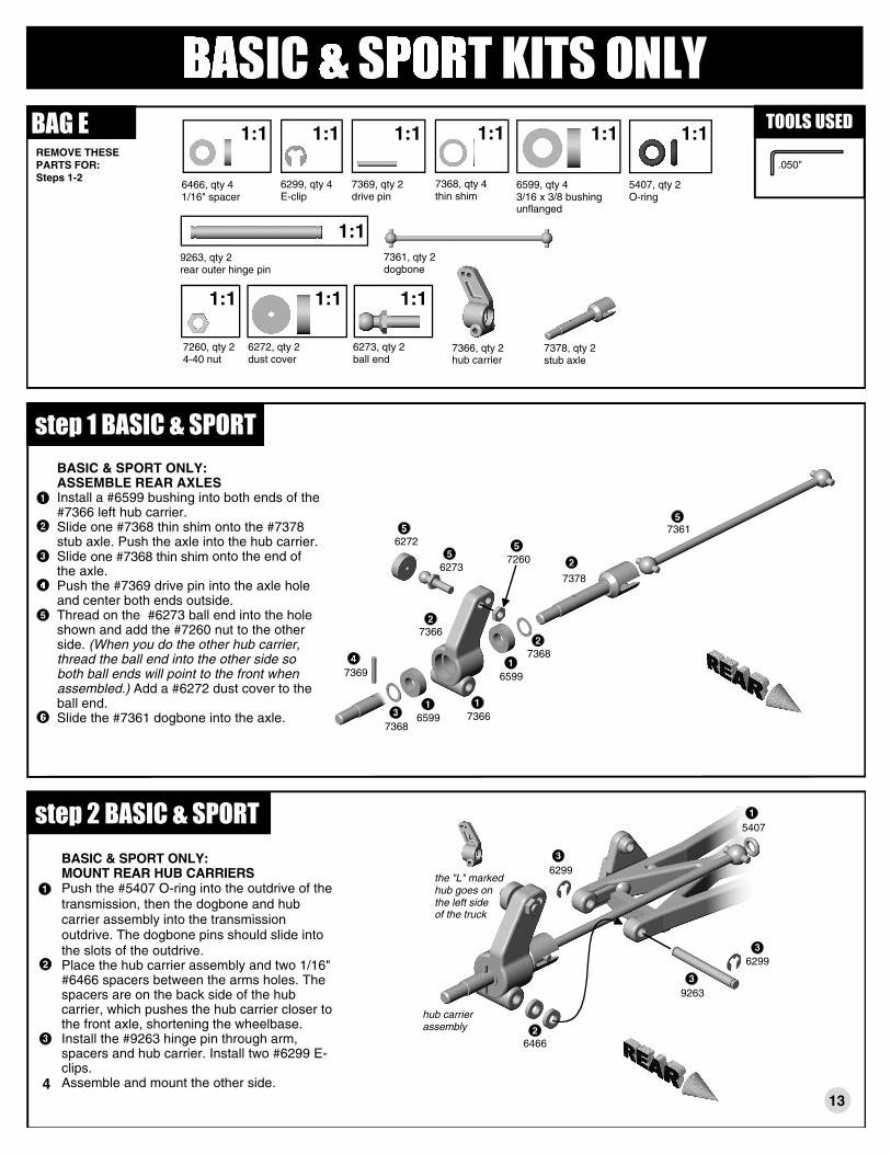
step 1 BASIC & SPORTBASIC & SPORT ONLY: ASSEMBLE REAR AXLESInstall a #6599 bushing into both ends of the #7366 left hub carrier. Slide one #7368 thin shim onto the #7378 stub axle. Push the axle into the hub carrier.Slide one #7368 thin shim onto the end of the axle.Push the #7369 drive pin into the axle hole and center both ends outside.Thread on the #6273 ball end into the hole shown and add the #7260 nut to the other side. (When you do the other hub carrier, thread the ball end into the other side so both ball ends will point to the front when assembled.) Add a #6272 dust cover to the ball end.Slide the #7361 dogbone into the axle. 7366
7366
7369
6273
6599
7361
13
BAG EREMOVE THESE PARTS FOR:Steps 1-2
TOOLS USED
.050"
6466, qty 41/16" spacer
1:1
9263, qty 2rear outer hinge pin
1:1
6299, qty 4E-clip
1:1
7369, qty 2drive pin
1:1
6599, qty 43/16 x 3/8 bushingunflanged
1:1
5407, qty 2O-ring
1:1
7378, qty 2stub axle
7361, qty 2dogbone
6299
9263
6299
5407
4
hub carrierassembly
the "L" markedhub goes on the left sideof the truck
BASIC & SPORT ONLY: MOUNT REAR HUB CARRIERSPush the #5407 O-ring into the outdrive of the transmission, then the dogbone and hub carrier assembly into the transmission outdrive. The dogbone pins should slide into the slots of the outdrive. Place the hub carrier assembly and two 1/16" #6466 spacers between the arms holes. The spacers are on the back side of the hub carrier, which pushes the hub carrier closer to the front axle, shortening the wheelbase.Install the #9263 hinge pin through arm, spacers and hub carrier. Install two #6299 E-clips.Assemble and mount the other side.
6599
7368
7368
6272
7260
7378
step 2 BASIC & SPORT
6466
7366, qty 2hub carrier
1:1
7368, qty 4thin shim
7260, qty 24-40 nut
6272, qty 2dust cover
1:1 1:1 1:1
6273, qty 2ball end
7260
TOOLS USEDBAG EREMOVE THESE PARTS FOR:
Steps 3-4
6292, 6934*, qty 24-40 x 3/8
6915, qty 24-40 x 5/8
1:1
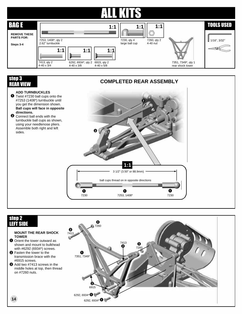
MOUNT THE REAR SHOCK TOWEROrient the tower outward as shown and mount to bulkhead with #6292 (6934*) screws.Fasten the tower to the transmission brace with the #6915 screws.Add two #7413 screws in the middle holes at top, then thread on #7260 nuts.
1:1
7413, qty 24-40 x 3/4
1:1
7260, qty 24-40 nut
14
step 2LEFT SIDE
REAR VIEW
1/16", 3/32"
COMPLETED REAR ASSEMBLYstep 3
ADD TURNBUCKLESTwist #7230 ball cups onto the #7253 (1408*) turnbuckle until you get the dimension shown. Ball cups will face in opposite directions.Connect ball ends with the turnbuckle ball cups as shown, using your needlenose pliers. Assemble both right and left sides.
7230, qty 4large ball cup
1:1
7351, 7349*, qty 1rear shock tower
1:1
ball cups thread on in opposite directions
3 1/2" (3.50" or 88.9mm)
7230 72307253, 1408*
1:1
7260
6292, 6934*
7253, 1408*, qty 22.62" turnbuckle
1:1
7351, 7349*
6292, 6934*
6915
7413
7413

15
step 1
1:1
6465, qty 2shock piston #1
BAG FREMOVE THESE PARTS FOR:Steps 1-2
REMOVE SHOCK PARTSRemove the #6440 shock parts from the molding tree carefully so no part of the molding runner remains. It is safer to remove a tiny amount of the shock part than to risk the chance of a burr remaining on the part. Short blade scissors or a hobby knife will work.
1:1
5407, qty 8red O-ring
TEAM/FT 7410, qty 21.39 rear shock body
1:1
6465, qty 2shock piston #2
6440, qty 4split locking washer
1:1
6440, qty 8small spacer
1:1
6440, qty 4large spacer
6429, qty 1shock assembly tool
5422, qty 130 wt oil
TEAM/FT 6436, qty 21.02 front shock body
6465
TRIM SHOCK PISTONSBurrs interfere with smooth shock action within the shock body. To remove from tree without creating burrs, twist up, not down. Remove two each of #1 and #2.Remove remaining burrs carefully with hobby knife.
burr
wrong
right
2
step 2Install the shock parts onto the #6429 shock tool as shown. One shock clip (split locking washer), one thin spacer, one red O-ring, one thick spacer, one red O-ring, and one thin spacer.Remove the #5422 oil and add 3-4 drops to the inside of the shock body and to the seal parts.Insert the tool and the seal parts into the shock body all the way. Push easily until the parts snap into place.Check the tool height in fig. 2-4. The left shock shows just before snapping into place, the right shows after.Assemble the remaining shocks the same way.If your shocks do not snap together easily, check the internal parts for burrs again.
DISMANTLING SHOCK PARTSHere is how to dismantle the shocks when it's rebuild time. Put the shock assembly tootip into thebottom the shock until it rests against the small washer as shown, then push to unclip the shock clip (split locking washer).
5422OIL
6429
5407
OIL
5422
fig. 2-4
BEFORESNAP
AFTERSNAP
6429
6440
smallwasher
shockclip
shock tooltip
shockinterior
5
BASIC/SPORT 7411, qty 2gold 1.39 rear shock body
BASIC/SPORT 6425, qty 2gold 1.02 front shock body
TOOLS USED

16
6
step 3
BAG FREMOVE THESE PARTS FOR:Steps 3-4
TOOLS USED
ASSEMBLE SHOCKSInstall the #6469 large O-ring over the thread of each shock body.On the #6459 (6417*) front shock shaft, install a #6299 E-clip on both sides of the #6465 (#2) piston from step #1.On the #6458 (6416*) rear shock shaft, install a #6299 E-clip on both sides of a #6465 (#1) piston from step #1.Insert the shock shaft assemblies into the shock bodies. Push the #7217 pivot ball and eyelet together. As you hold the shaft with a rag and needlenose pliers next to the threads, screw the eyelet onto the end of each shock shaft.
1:1
6469, qty 4large O-ring
6469
6459,6417*
6299
6465 (#2)
6465 (#1)
7217 pivot ball
7217 eyelet
64696299
6458,6416*
6299
6299
7217 pivot ball
7217 eyelet
FRONT
REARTEAM/FT 7410SPORT/BASIC 7411
1:1
6459, 6417*, qty 21.02 front shock shaft
6458, 6416*, qty 21.32 rear shock shaft
1:1
6299, qty 8E-clip
1:1
1:1
6465, qty 2shock piston #1(for rear shocks)
1:1
6465, qty 2shock piston #2(for front shocks)
7217, qty 4pivot ball
7217, qty 4eyelet
6428, qty 4shock cap
FILLING THE SHOCKS Holding the shocks upright, fill with oil to the top of the shock body. Slowly move the shaft up and down several times to allow air bubbles to escape to the top. Refill with oil to the top of the shock body. Push the shaft in until the piston is level with top of shock body. The oil will slightly bulge up above the shock body. Fill the #6428 shock cap about halfway with oil and install it onto the body. Try to retain as much oil as possible during assembly. The shaft will extend out as you tighten the cap down.
SETTING THE REBOUND Move the shock shaft in and out a few times and then push it all the way in. It should be easy to push the shaft in until the eyelet hits the body.
1/4" to 3/8"(6.3mm - 9.5mm")
6428
HOW TOTIGHTEN THE CAP ON YOUR
SHOCK
Then the shaft should push itself out approximately 1/4" to 3/8" (6.3mm - 9.5mm"). If the shock does not push out this far, there is not enough oil in them. Add just a little oil and try steps 6-7 again. If the shocks push out farther than the distance in step seven, or you cannot push the shaft in until the eyelet hits the body, there is too much oil. Loosen the cap a half turn (with the shaft extended) and pump out a small amount of oil by pushing the shaft in. Retighten the cap and try steps 6-7 again.
step 4
shock body
shaft
eyelet
5422, qty 130 wt oil
TEAM/FT 6436SPORT/BASIC 6425

step 5
BAG FREMOVE THESE PARTS FOR:Step 5
TOOLS USED
3/32"
FINISH SHOCKSSlide one #8846 1/4" preload spacer onto the rear shock body.Slide one #8846 1/16" and one 1/8" preload spacer onto the front shock body.Slide on the #6475 spring collar, then #6480 green springs on the rear shocks, and #7427 green springs on the front shocks.Compress the springs to add the #6475 spring cup.
1:1
8846, qty 2- 1/16", 2-1/8", 2-1/4"preload spacers
FRONT
REAR
1/16"
1/4"
1/8"
8846
8846
8846
6475
spring collar
REAR: 6480 greenFRONT: 7427 green
6475
spring cup
6475, qty 4spring collar
6475, qty 4spring cup
6480, qty 2rear green spring
7427, qty 2front green spring
17
REAR SHOCK MOUNTINGAdd the #6473 bushings as shown.Push shock cap over bushing and add #6472 locknut. Do not overtighten or the shock will bind.Fasten the lower shock with the #6918 screw into the arm outer hole.Do the other rear shock.
FRONT SHOCK MOUNTINGAdd the #6473 bushings as shown.Push shock cap over bushing and add #6472 locknut. Do not overtighten or the shock will bind.Fasten the lower shock with the #6918 screw into the arm's middle hole.Do the other front shock.
6472, qty 44-40/5-40locknut
BAG FREMOVE THESE PARTS FOR:
Steps 6-76918, qty 44-40 x 1/2
6473, qty 4shock bushing
1:11:1 TOOLS USED
step 6RIGHT SIDE
step 7RIGHT SIDE
1/16", 3/32"
1
4
in middle hole of shock tower
in middle hole of arm
4in outer hole of shock tower6473
6472
6918
6473
6472
6918

BAG GREMOVE THESE PARTS FOR:
Step 2
9170, qty 2servo link cup
9170, qty 1servo link
MOUNT THE SERVOMount the servo with two #7673 (6933*) screws.Assemble the #9170 servo link, matching the length to the true scale drawing. Use needle-nose pliers to attach link to ball ends.
7673, 6933*, qty 24-40 x 5/16
1:1
13/16".812"
20.4mm
9170 9170
BAG G6515, qty 23mm x 6mmgold
1:1 1:1
6936, qty 2#4 washer
1:1
6951, qty 14-40 x 1/8set screw
SPORT ONLY6681, qty 123 toothpinion gear
SPORT ONLY6742, qty 1motor connection plug
SPORT ONLY580, qty 1motor
SPORT ONLY6520, qty 3.1uf capacitor
1:11:1
9170
TOOLS USED
18
.050", 1/16"
step 2RIGHT SIDE
TOOLS USED
.050", 3/32"
7673,6933*
1:1
7673,6933*
BAG G
9180, qty 1 easervo horns
1:1
ASSEMBLE THE SERVOFind the approporiate #9180 servo horn for your servo, marked "A" for Airtronics, "F" for Futaba, "J" for JRPropo, and "H" for Hitec. Remove the servo horn from your servo and replace with the #9180 horn, then fasten with the stock mounting screw.Install the #6270 ball end into the servo horn. Add the #6272 dust cover.Attach the #7336 mounts with the #6917 (6860*) screws and #7337 washers. Add the #7336 spacers if you have an Airtronics servo.
6270, qty 1ball end
6272, qty 1dust cover
7336, qty 2servo mount
7336, qty 2servo mountspacer
7337, qty 4washer
1:11:1 TOOLS USED
step 1
1/16"REMOVE THESE PARTS FOR:
Step 1
6917, 6860*
use spacers with Airtronics servo
BASIC, SPORT, TEAM ONLY6917, qty 44-40 x 3/8
ORFT ONLY6860*, qty 44-40 x 3/8
1:11:1
9180
62706272
7336
7336servo mount
7337
7337
6917, 6860*
6917, 6860*
stock mountingscrew
REMOVE THESEPARTS FOR:
Step 3
#2 washer3721
#2 screw
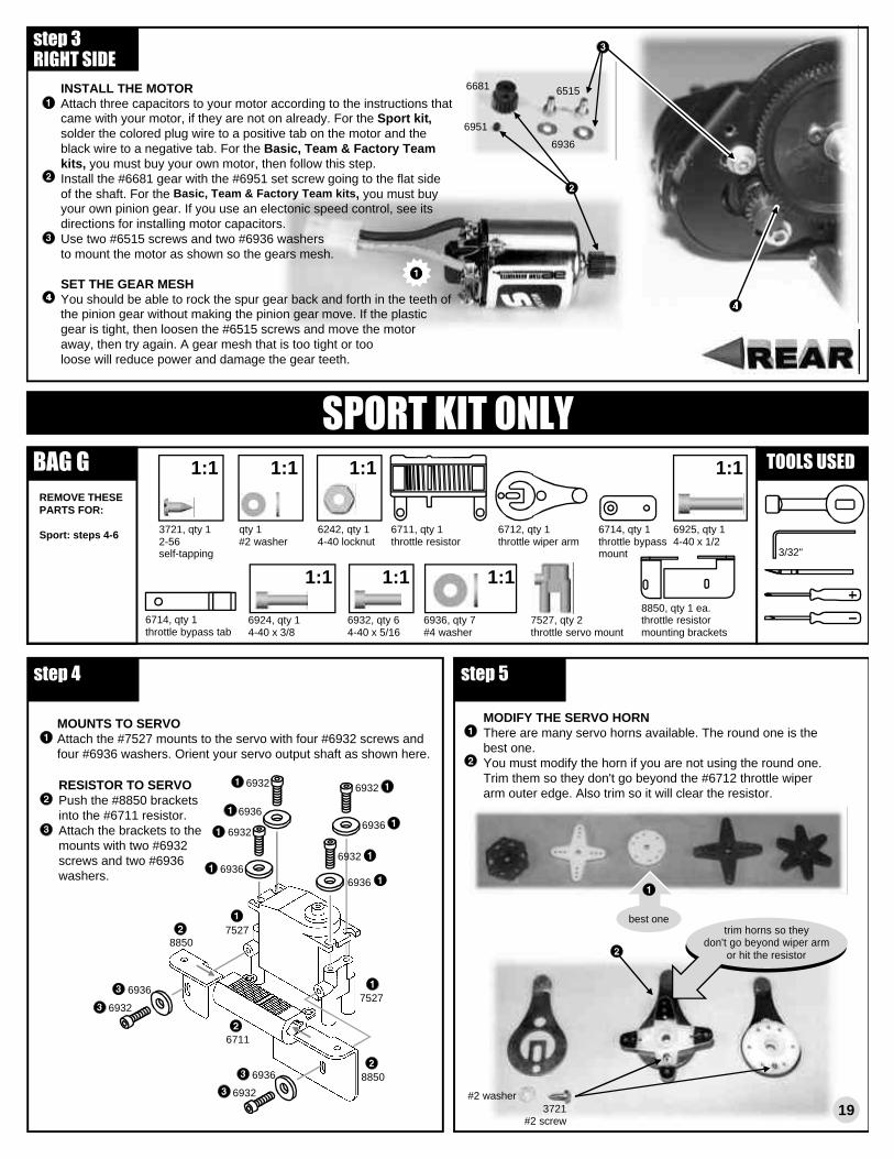
MODIFY THE SERVO HORNThere are many servo horns available. The round one is the best one.You must modify the horn if you are not using the round one. Trim them so they don't go beyond the #6712 throttle wiper arm outer edge. Also trim so it will clear the resistor.
BAG G
7527, qty 2throttle servo mount
1:1
MOUNTS TO SERVOAttach the #7527 mounts to the servo with four #6932 screws and four #6936 washers. Orient your servo output shaft as shown here.
6932, qty 64-40 x 5/16
1:1
6936, qty 7#4 washer
8850, qty 1 ea.throttle resistormounting brackets
6711, qty 1throttle resistor
6712, qty 1throttle wiper arm
6714, qty 1throttle bypassmount
6925, qty 14-40 x 1/2
6714, qty 1throttle bypass tab
6924, qty 14-40 x 3/8
1:1
1:1 1:1
RESISTOR TO SERVOPush the #8850 brackets into the #6711 resistor. Attach the brackets to the mounts with two #6932 screws and two #6936 washers.
6242, qty 14-40 locknut
TOOLS USED
step 4 step 5
19
3/32"
1:11:1
3721, qty 12-56self-tapping
qty 1#2 washer
REMOVE THESE PARTS FOR:
Sport: steps 4-6
SPORT KIT ONLY
best onetrim horns so they
don't go beyond wiper armor hit the resistor
7527
7527
69326932
6936
8850
6711
6932
6932
6932
6936
6936
6936
6932
6936 8850
6936
6681
6951
6936
6515INSTALL THE MOTORAttach three capacitors to your motor according to the instructions that came with your motor, if they are not on already. For the Sport kit, solder the colored plug wire to a positive tab on the motor and the black wire to a negative tab. For the Basic, Team & Factory Team kits, you must buy your own motor, then follow this step.Install the #6681 gear with the #6951 set screw going to the flat side of the shaft. For the Basic, Team & Factory Team kits, you must buy your own pinion gear. If you use an electonic speed control, see its directions for installing motor capacitors.Use two #6515 screws and two #6936 washers to mount the motor as shown so the gears mesh.
SET THE GEAR MESHYou should be able to rock the spur gear back and forth in the teeth of the pinion gear without making the pinion gear move. If the plastic gear is tight, then loosen the #6515 screws and move the motor away, then try again. A gear mesh that is too tight or too loose will reduce power and damage the gear teeth.
step 3RIGHT SIDE

BAG G
WIRE THE RESISTORSolder the short red wire between the positive resistor tab and the brass bypass tab.Solder the #6745 harness wires to the wiper arm and negative tab on the resistor.Solder the #6747 harness to the positive and negative tabs on the resistor.Run the wire of the servo attached to the resistor through the battery slot area.
6747
SPEED CONTROL TO CHASSISAttach speed control to chassis with two #6917 screws from the bottom.
6745
6745, qty 1motor output harness
6747, qty 1battery input harness
6917, qty 24-40 x 3/8
1:1
PARTS REMOVED TO IMPROVE CLARITY
BEC plug
6727, qty 1servo tape
TOOLS USED
step 7 step 8LEFT SIDE
1/16"
20
red
black
REMOVE THESE PARTS FOR:
Sport: steps 7-9
SPORT KIT ONLY
6917
PARTS REMOVED TO IMPROVE CLARITY
6917
FINAL RESISTOR/ SERVO ASSEMBLYAttach the #6712 arm to the horn with the #3721 screw and #2 washer.Mount the arm and horn to the servo with the screw from your servo. Trim the #3721 screw tip if it contacts the servo body.Add the #6714 mount using #6925 screw and #6242 locknut.Add the #6714 bypass tab to the #6714 mount with a #6924 screw and #6936 washer.
step 6
ASSEMBLED THROTTLE ARM AND RESISTOR
6712 arm
horn
3721#2 screw
6714
6925
6242
6714
6936
6924screw fromyour servo
#2 washer

BAG HREMOVE THESE PARTS FOR:
Steps 1-26285, qty 24-40 x 1/4
1:1
INSTALLING THE BATTERY PACKInstall the three #9235 foam battery pads.Install the four #9238 foam battery spacers. (The tuning section will show you how to adjust your steering or traction by moving these spacers.)Install your battery pack. (See section at right if you need to assemble it first.)Thread on the #6929 screw. Aim the body clip hole across the chassis. Add the #7333 (7334*) battery hold down strap. Adjust the screw so the batteries are held tight, but you are still able to push the #6332 body clip through the screw.
9247, qty 1gear cover
9247, qty 1button
9235, qty 1foam battery pads
9238, qty 4battery spacer
6929, qty 14-40 x 3/8
1:1
7333, 7334*, qty 1battery hold down strap
6332, qty 1body clip
SOLDERING INDIVIDUAL CELLSSolder connections properly to assemble a battery pack from individual cells.TIP: Team racers prefer battery bars or braid for sturdier connections. Insulated wire will not allow the pack to fit in the battery slot.
solder connectionswith battery bars
or braid
BATTERY PRODUCTS ARENOT INCLUDED IN KIT
TOOLS USED
21
3/32"
step 1LEFT SIDE
9238
9235
hook into rear shock tower as shown
92389238
9238
6929 6332
7333,7334*
RADIO RECEIVER TO CHASSISCut a piece of servo tape, remove the paper from one side, and attach it to the bottom of your receiver.Slip the receiver wire through the built-in chassis antenna mount.Remove the paper from the other side and attach to the chassis as shown.Plug the small #6747 BEC plug (of step 7) into the receiver's on/off switch.Follow the instructions that accompany your radio receiver system.
step 9LEFT SIDE
5

BAG HREMOVE THESE PARTS FOR:
Steps 3-4
RADIO AND RECEIVER INSTALLATIONInstall your battery pack as shown. If you need to assemble the battery, see step 1 #5 on page 21.Cut a piece of servo tape and use it to attach your ESC and switch where shown.Cut a piece of servo tape and use it to attach your receiver where shown.Connect the ESC and steering servo to your receiver according to your radio or ESC instructions, then connect the motor to your ESC.
6727, qty 1servo strip
TOOLS USED
step 3
MOUNT THE ANTENNAPush your reciever wire through the built-in antenna mount hole.Thread the wire through the #6338 antenna and push the antenna firmly into the chassis' antenna mount hole.Add the #6338 cap to the other end of the antenna tube.
6338
6338, qty 1antenna tube cap
6338, qty 1antenna tube
step 4
6338
22
RECEIVER
ESC
SERVOSERVO
GEAR COVERTrim the #9247 gear cover, cutting out three holes shown. Insert the #9247 insert button into the large hole cut into the gear cover.Mount the cover with two #6285 screws.
RIGHT SIDE
9247
6285

23
BODY MOUNTINGTrim and paint the body. (See painting instructions on page 25 if you have not painted before.) Trim the spoiler from the body as shown in step 3 below.Secure the body to the chassis with three #6332 body clips where shown.
REMOVE THESE PARTS FOR:
Step 5
6332, qty 2body clip
TOOLS USED
step 5
BAG H
1/16"
cut openingsfor body
body mounts
body mount
antenna
spoiler
TEAM & FACTORY TEAMBASIC & SPORT KITS
(spoiler is not included in kit)
cut openings for wheels
TEAM & FACTORY TEAM
BASIC & SPORT KITS(spoiler is not included in kit)
cut openings for wheels
rear body clipfront body clips
SPOILER MOUNTING(Spoiler is not included in Basic & Sport kits. Order #7185 Spoiler from Associated.)Cut spoiler from body where shown.Mount to rear of body using 4-40 nuts and screws.
cut from body
cut holes for screwsin body and spoiler
mount spoiler with screws thrutop and nuts underneath
6222, qty 24-40 nylon nut
6919, qty 24-40 x 5/16 screw
1:1 1:1

REMOVE THESE PARTS FOR:
Steps 1-2
7803, qty pr1 pc rear wheels
7824, qty 2rear tire
3438, qty 28-32 locknut
7842, qty pr1 pc front wheels
7877, qty prfront tire
BASIC/SPORT ONLY6599, qty 43/16 x 3/8unflanged bushing
6222, qty 24-40/5-40 locknut
1:1 1:1 1:1 TOOLS USED
24
3/32"
BAG I
TEAM/F.T. ONLY3977, qty 43/16 x 3/8unflanged ball bearing
1:1
step 1REAR WHEELS AND TIRESMake a 1/8" hole in the #7803 wheel.Make sure the #7880 foam insert is centered in the #7824 tire.Install the tire onto the wheel. Glue the tire to the wheel with cyanoacrylic glue in four spots around the tire on both sides. WARNING: Follow the adhesive instructions for proper use and safety. Wear eye and hand protection.Install the wheel assembly onto the axle, lining up the roll pin with the slot in the wheel. Thread on the #3438 locknut.Finish the second rear wheel and tire.5
FRONT WHEELS AND TIRESMake a 1/8" hole in the #7842 wheel.Make sure the #7880 foam insert is centered in the #7877 tire.Install the tire onto the wheel. Glue the tire to the wheel with cyanoacrylic glue in four spots around the tire on both sides.Insert the #3977 bearings or #6599 bushings into both sides of the front wheel.Install the wheel assembly onto the axle. Thread on the #6222 locknut.Finish the second front wheel and tire.6
7880, qty 4foam tire insert
7803
7880 7824
3438
7842
7880 7877
39776222
Put "V" groovestoward outside
FRONT TIRE

APPARELAll shirts printed front & back in full
color on 100% cotton T’s.
B3 ‘97 WORLD’S#SP-41
M L XL $13.00*
XXL $15.00*
#SP-42 front (back has GT)T3/GT T-SHIRT#SP-42
M L XL $13.00*
XXL $15.00*
#SP-43 backREEDY’S WORLD T-SHIRT#SP-43
M L XL $13.00*
XXL $15.00*( * ) = non-standard discount item.( ** ) = short discount or net item.
APPAREL
FACTORY TEAM CAPS.Low crown style. Heavy brushedtwill caps have contrasting stitch.Buckle back adjustable. One sizefits all.
#SP-406 Blue $15.95*
#SP-407 Black $15.95*
#SP-410 frontTEAM ASSOCIATED JACKET#SP-410. Fully lined
M L XL $59.95**
XXL XXXL $59.95**
TC3 T-SHIRT#SP-44
M L XL $13.00*
XXL $15.00*
CAR CARRIER
ASSOCIATED CAR CARRIERBAG. Heavy duty reinforced nylonwith brass zipper. (Boxes notincluded.)
#SP-415 $39.95**
ASSOCIATED CAR CARRIERBOX. Fits inside #SP-415 bag.Double thickness box with lockingend flap. Includes three 24 x 12 x 6”inner boxes. See photo. (Bag notincluded.) Due to its large size, add$15.00 to shipping charges.
#SP-100 $15.00**
INNER BOXES fit snugly in #SP-100 car carrier box. Three included,size 24 x 12 x 6” each. (Bag andouter box not included.)
#SP-101 $5.25**
MOUSEPAD
TEAM ASSOCIATED OFF ROADMOUSE PAD
#SP-200 $9.99*
DECALSAll decals are Mylar
peel-and-stick.
TEAM ASSOCIATED LOGOS#3820 $2.00
FACTORY TEAM LOGOS#3825 $2.00
REEDY MODIFIED LOGOS.#718 $3.50
COMPLETE TUNING GUIDE: T3#7194 $3.95
ORDERING INSTRUCTIONS:1. Make a copy of this page.2. Write in the boxes the quantity for each item ordering.3. Fill out complete shipping info. Please pay by check ormoney order or international money order if pre-paying.4. Credit card orders will only be sent to credit card billingaddress.5. Fill out address below & send order to address at top.
Name _________________________________________
Address________________________________________
Address _______________________________________
City,State, Zip __________________________________
Phone ( )
CREDIT CARD PAYMENTS:Credit card orders can only be sent to the creditcard billing address. The address below mustmatch the billing address or the order will not beprocessed.
Circle card: VISA MC AmEx DiscoverName as it appears on card:
_______________________________Card # __________________________Expiration date: ____________________
Signature:
Total cost of items above
Sales tax: 7.75% (CA residents only)
Shipping (in U.S.A.) $4.50
Car Carrier Box shipping $15.00
TOTAL
ORDER FORM
EXCITING PRODUCTS FROM TEAM ASSOCIATED!Associated Electrics, Inc. 3585 Cadillac Ave. Costa Mesa, CA 92626-1401