asteroid mission design software tool (amidst) for planetary
TRANSCRIPT

Asteroid Mission Design Software Tool for Planetary
Defense Applications
George Vardaxis∗ and Bong Wie†
Iowa State University, Ames, Iowa, 50011, United States
As the number of identified potentially hazardous near-Earth asteroids increases,the ability to track their orbits and plan for deflection/disruption missions ceases tobe a simple exercise but a necessity. There exist several software tools to performtrajectory and mission optimization, but they tend to only focus on the mission tra-jectory optimization. This paper presents the tools and architecture of the AsteroidDeflection Research Center’s Asteroid Mission Design Software Tool (AMiDST),taking into account the mission launch configuration, target aquisition, the post-encounter trajectory of the object, and mission cost estimation. Using AMiDSTtwo mission examples are examined for asteroids 1999 RQ36 and 2011 AG5, as wellas the trajectory tracking of Apophis, to demonstrate the capabilities of this tool.
Nomenclature
~f non-conservative perturbation accelerationAU astronomical unitTU solar time unita semi-major axis, AUe orbital eccentricityi orbital inclination, degn number of perturbing bodies~r asteroid position vector~rk planet position vector∆V change in velocity magnitude, km/sΩ longitude of the ascending node, degω argument of periapse, degµ solar gravitational parameter, AU3/TU2
µk planetary gravitational parameter, AU3/TU2
Subscriptk index of gravitational perturbing bodies
I. Introduction
The threat of asteroids impacting the Earth is very real and must be taken seriously. Instead ofhoping for a successful mission to the threatening near-Earth object (NEO) when the time comes,
∗Graduate Student, Department of Aerospace Engineering, 1200 Howe Hall.†Vance Coffman Endowed Chair Professor, Department of Aerospace Engineering, 1200 Howe Hall.
1 of 22
American Institute of Aeronautics and Astronautics
Page 1 of 22
http://mc.manuscriptcentral.com/aiaa-mgnc12
AIAA GNC/AFM/MST/ASC 2012

or assuming that day will never come, demonstrations of missions to near-Earth asteroids canprovide knowledge and experience that may prove vital, should similar missions be needed in thefuture. The focus of this paper is two-fold: (1) preliminary mission design for direct intercept andrendezvous missions to target NEOs and (2) precision, long-term N-body simulations of asteroidorbits about the Sun. Focus for the mission design portion will be on asteroids 1999 RQ36 and 2011AG5 due to their high impact probabilities. The work in long-term, precision orbit determinationis focused on the asteroid Apophis.
Previous research activities at the Asteroid Deflection Research Center (ADRC) have includedasteroid target selection, preliminary hypervelocity nuclear interceptor system (HNIS) designs, andpreliminary mission designs to asteroids 1998 SB15, 2003 QC, and 2011 BX10.1–3 The preliminarymission designs have included decisions on the launch vehicle, OTV (orbital transfer vehicle) opti-mization, and initial mission orbit determination using a Lambert solver. Asteroid target selectionand mission designs along with general mission analysis are components of an overall, completemission design concept, previously left separate to focus on the individual components themselves.In this paper target selection and preliminary mission design concepts are combined and treatedas components of an overall NEO mission design tool in development at the Iowa State ADRC.
Precision orbit determination is a third component added to the mission design tool to enhanceits overall strength. Precise trajectory tracking using an N-body gravitational simulator can proveto be a powerful tool, either to calculate impact probabilities of asteroids with Earth or find thetrajectories of perturbed bodies. Together, the the asteroid target selection, preliminary missiondesign process, and precision orbit tracking components are joined to create the ADRC’s AsteroidMission Design Software Tool (AMiDST) - a multi-purpose, scalable configuration design programfor asteroid deflection/disruption missions.
II. Overview of Existing Mission Design Tools
II.A. Pre-Mission Design Process Algorithm
The initial mission design program, used for hypervelocity nuclear interceptor spacecraft (HNIS)to disrupt Earth-threatening asteroids, was primarily a pre-mission design software tool. It wascomprised of several functions and subroutines calculating several preliminary design variables.4
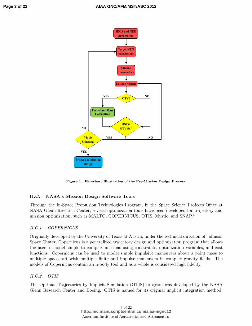
The program assumed the HNIS was comprised of a leader and follower spacecraft carrying a nuclearexplosive device (NED) for a penetrated subsurface explosion mission. Using the information aboutthe masses of the HNIS bus and NED payload, mission ∆V or C3 needed to reach a target NEO,and class of launch vehicles to be analyzed, the algorithm begins the process of calculating thepayload capacity of the launch vehicles, mission details, and analyzing the solution. A flowchart ofthe pre-mission design process is provided in Figure 1.4
II.B. An On-line Tool by The Aerospace Corporation
The Aerospace Corporation is developing an on-line tool to aid in the design and understandingof deflection impulses necessary for guarding against objects that are on an Earth-impacting tra-jectory. Using several variables to characterize the target NEO (warning time, size/density, orbitparameters, etc.) and mitigation mission design parameters (∆V impulse vector, number of daysbefore impact to launch, number of days before impact to deflect, etc.), users can simulate thedesigned mission transfer from Earth to the target NEO and deflected NEO orbit. After the ap-plied deflection and propagation time, the Earth miss distance would be determined on the EarthB-plane in Earth radii. This on-line tool is still under development, with the hopes of incorporatingseveral more design variables and limitations to only allow feasible mission designs based on currentlaunch and mission capabilities.5
2 of 22
American Institute of Aeronautics and Astronautics
Page 2 of 22
http://mc.manuscriptcentral.com/aiaa-mgnc12
AIAA GNC/AFM/MST/ASC 2012
HNIS and NED
parameters
OTV? NO YES
Launch Vehicle
Propellant Mass
Calculation
Target NEO
parameters
Mission
parameters
HNIS/
OTV fit?
YES Viable
Solution?
NO
NO
YES
Proceed to Mission
Design
Figure 1. Flowchart Illustration of the Pre-Mission Design Process.
II.C. NASA’s Mission Design Software Tools
Through the In-Space Propulsion Technologies Program, in the Space Science Projects Office atNASA Glenn Research Center, several optimization tools have been developed for trajectory andmission optimization, such as MALTO, COPERNICUS, OTIS, Mystic, and SNAP.6
II.C.1. COPERNICUS
Originally developed by the University of Texas at Austin, under the technical direction of JohnsonSpace Center, Copernicus is a generalized trajectory design and optimization program that allowsthe user to model simple to complex missions using constraints, optimization variables, and costfunctions. Copernicus can be used to model simple impulsive maneuvers about a point mass tomultiple spacecraft with multiple finite and impulse maneuvers in complex gravity fields. Themodels of Copernicus contain an n-body tool and as a whole is considered high fidelity.
II.C.2. OTIS
The Optimal Trajectories by Implicit Simulation (OTIS) program was developed by the NASAGlenn Research Center and Boeing. OTIS is named for its original implicit integration method,
3 of 22
American Institute of Aeronautics and Astronautics
Page 3 of 22
http://mc.manuscriptcentral.com/aiaa-mgnc12
AIAA GNC/AFM/MST/ASC 2012
but includes capabilities for explicit integration and analytic propagation. Earlier versions of OTIShave been primarily been launch vehicle trajectory and analysis programs. Since then, the programhas been updated for robust and accurate interplanetary mission analyses, including low-thrusttrajectories. OTIS is a high fidelity optimization and simulation program that uses SLSQP andSNOPT to solve the nonlinear programming problem associated with the solution of the implicitintegration method.
II.C.3. Mystic
Mystic, developed at the Jet Propulsion Laboratory (JPL), uses a Static/Dynamic optimal control(SDC) method to perform nonlinear optimization. The tool is an n-body tool and can analyzeinterplanetary missions as well as planet-centered missions in complex gravity fields. One of thestrengths of Mystic is its ability to automatically find and use gravity assists, and also allowsthe user to plan for spacecraft operation and navigation activities. The mission input and postprocessing can be performed using a MATLAB based GUI.
II.D. NASA’s General Mission Analysis Tool
Developed by NASA Goddard Space Flight Center, the General Mission Analysis Tool (GMAT)is a space trajectory optimization and mission analysis system. Analysts use GMAT to designspacecraft trajectories, optimize maneuvers, visualize and communicate mission parameters, andunderstand mission trade space. GMAT has several features beyond those that are common to manymission analysis systems, features that are less common or unique to GMAT. Its main strength overother software choices is GMAT’s versatility. Its scripting ability is easy to use and edit withoutknowledge of computer languages. And, the MATLAB plug-in allows an expansion of the user’sability to personalize each mission.7
II.E. Asteroid Mission Design Software Tool (AMiDST)
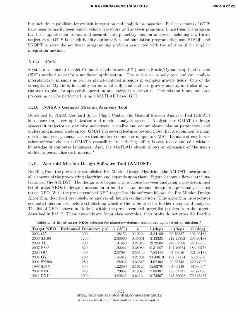
Building from the previously established Pre-Mission Design Algorithm, the AMiDST incorporatesall elements of the pre-existing algorithm and expands upon them. Figure 2 shows a flow-chart illus-tration of the AMiDST. The design tool begins with a choice between analyzing a pre-determinedlist of target NEOs to design a mission for or build a custom mission design for a personally selectedtarget NEO. With the pre-determined NEO target list, the software follows the Pre-Mission DesignAlgorithm, described previously, to analyze all launch configurations. This algorithm incorporatesestimated mission cost before establishing which is the to be used for further design and analysis.The list of NEOs, shown in Table 1, within the pre-determined target list is taken from the targetsdescribed in Ref. 7. These asteroids are Amor class asteroids, their orbits do not cross the Earth’s
Table 1. A list of target NEOs selected for planetary defense technology demonstration missions.8
Target NEO Estimated Diameter (m) a (AU) e i (deg) ω (deg) Ω (deg)2003 GA 300 1.28153 0.19124 3.84189 66.76837 192.931862006 SJ198 1200 2.08969 0.45631 2.43325 212.25852 266.891382009 TB3 300 1.31863 0.21926 12.22404 249.57728 22.179382007 FS35 620 1.92244 0.38986 0.31887 107.40624 183.007562003 QC 400 2.57094 0.53140 7.85444 37.43616 321.681832004 GY 480 1.44817 0.21804 23.43610 182.87114 50.887062001 SX269 280 1.88042 0.34613 4.02404 29.53738 320.170921998 SB15 330 1.22609 0.16126 15.62791 67.63148 67.936952004 KE1 240 1.29867 0.18079 2.88387 283.67731 42.774682011 BX10 1000 2.82541 0.64134 9.73567 348.36692 79.118387
4 of 22
American Institute of Aeronautics and Astronautics
Page 4 of 22
http://mc.manuscriptcentral.com/aiaa-mgnc12
AIAA GNC/AFM/MST/ASC 2012

Asteroid Mission Design Software Tool
START
P/C Custom Mission Design
Target List
Mission Design
Pre-Mission
Design Process
Algorithm
i = 1,…,n
NEO and Mission
parameters
HNIS/KI HNIS KI
Impactor, Follower,
NED mass
Satellite
Mass
Mission
Type Porkchop Plot
Impact Angle
Mission Cost
Complete Mission
Design
Perturbed NEO
trajectory
Launch Date and
Mission Duration
HNIS
KI
HNIS
Launch Configu-
ration Analysis
Algorithm
i = 1,…,n
Mission Cost
Figure 2. Flowchart Illustration of the AMiDST.
path, and therefore pose no threat to the planet. Due to the non-existant threat that these aster-oids possess towards Earth, the pre-determined target list option is meant more as an introductionto some of AMiDST’s capabilities. A launch date is given for each individual asteroid, leaving noneed for too much user input. With the launch date determined and the target defined then thespacecraft’s orbital trajectory is well-defined and no longer a concern. The AMiDST analyzes allthe possible launch configurations available to complete the mission, the arrival at the target NEO,and the estimated mission costs. The outputs are then made available for the user to examine andunderstand the results of the NEO mission design analyses. The spacecraft used for missions tothese asteroids is the ADRC’s HNIS spacecraft design. The results are not limited to a single HNISdesign (300-kg NED, 1000-kg NED, or 1500-kg NED), but include all three, and highlights the bestmission configuration for each type.
5 of 22
American Institute of Aeronautics and Astronautics
Page 5 of 22
http://mc.manuscriptcentral.com/aiaa-mgnc12
AIAA GNC/AFM/MST/ASC 2012

For custom mission designs, the user begins by entering information about the target NEO ofinterest and the low-Earth orbit (LEO) departure radius. Then the choice is given between twotypes of spacecraft to be used for the mission, the HNIS concept or a Kinetic Impactor (KI). ForHNIS spacecraft, information about the mass of the impactor, follower, and NED are obtainedfrom the user, while in the KI spacecraft case the total mass of the satellite is needed. In eithercase, the user is prompted with a decision between three mission types: a direct intercept, a directintercept at a relative speed of 10 kilometers per second, or rendezvous. The software tool thenloads the appropriate porkchop plot, showing the total required mission ∆V, where the user canselect as many design points as desired, resulting in a set of launch dates and mission durations.Given the launch date(s) and mission duration(s), the transfer orbit between Earth and the targetNEO is completely determined by Lambert’s Problem, allowing the possible launch configurationsfor the mission(s) to be analyzed along with their estimated mission cost and compared to come upwith the prefered launch configuration for each given mission. The resulting mission trajectoriesfor either the HNIS or KI spacecraft are provided along with the arrival impact angles. Since thepurpose of the HNIS design was total NEO disruption, the trajectory of the remaining asteroidfragments are not tracked, however in the case of the KI spacecraft the slightly perturbed NEO ispropagated forward in time to see how much the orbit has changed from the original, before theimpulse was applied.
II.F. Mission Design Program Comparisons
The trajectory and mission optimization tools developed through the In-Space Propulsion Tech-nologies Program are all rather high fidelity programs. One of the common denominators of allthese tools are that they primarily look at the intermediate stage of a mission, the spacecraft tra-jectory from one target to another. The other two mission stages are more or less overlooked incomparison to the spacecraft’s mission trajectory. The AMiDST does not currently possess thehigh-fidelity trajectory optimization of Copernicus, Otis, or Mystic, but instead focuses on thelaunch and terminal phase of an NEO mission.
Looking into several launch vehicle and spacecraft configurations to complete a given missiondesign to a designated target NEO, the mission design software evaluates the possible combinationsbased upon several evaluation criteria such as space in the launch vehicle fairing, mission ∆Vrequirements, and excess launch vehicle ∆V. A staple of this mission design tool is the evaluationof estimated total mission cost, the determining factor between mission configurations in the caseswhere more than one launch configuration can result in a successful mission.
The terminal phase of an NEO mission currently is limited to kinetic impact perturbations to atarget NEO’s orbital trajectory. Using the impact angle and arrival velocities of both the spacecraftand target NEO, along with both masses, the trajectory of the perturbed asteroid is tracked inorder to find how much the trajectory is altered from the previous unperturbed orbit. Dependingon the chosen NEO, a mission can be designed to explore the capabilities of a kinetic impactor ona target NEO or to design a mission to deflect the target NEO from its Earth-impacting trajectory.
III. Reference Target Asteroids
Near-Earth Objects are asteroids and comets with perihelion distance (q) less than 1.3 astro-nomical units (AU). The vast majority of NEOs are asteroids, which are referred to as Near-EarthAsteroids (NEAs). NEAs are divided into three groups (Aten, Apollo, Amor) based on their per-ihelion distance, aphelion distance (Q), and semi-major axes (a). Atens are Earth-crossing NEAswith semi-major axes smaller than Earth’s (a < 1.0 AU, Q > 0.983 AU). Apollos are Earth-crossingNEAs with semi-major axes larger than Earth’s (a > 1.0 AU, q < 1.017 AU). Amors are Earth-
6 of 22
American Institute of Aeronautics and Astronautics
Page 6 of 22
http://mc.manuscriptcentral.com/aiaa-mgnc12
AIAA GNC/AFM/MST/ASC 2012
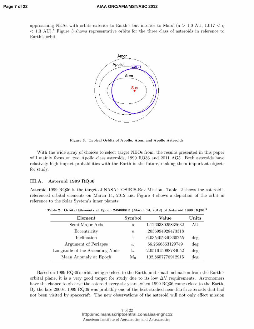
approaching NEAs with orbits exterior to Earth’s but interior to Mars’ (a > 1.0 AU, 1.017 < q< 1.3 AU).8 Figure 3 shows representative orbits for the three class of asteroids in reference toEarth’s orbit.
Figure 3. Typical Orbits of Apollo, Aten, and Apollo Asteroids.
With the wide array of choices to select target NEOs from, the results presented in this paperwill mainly focus on two Apollo class asteroids, 1999 RQ36 and 2011 AG5. Both asteroids haverelatively high impact probabilities with the Earth in the future, making them important objectsfor study.
III.A. Asteroid 1999 RQ36
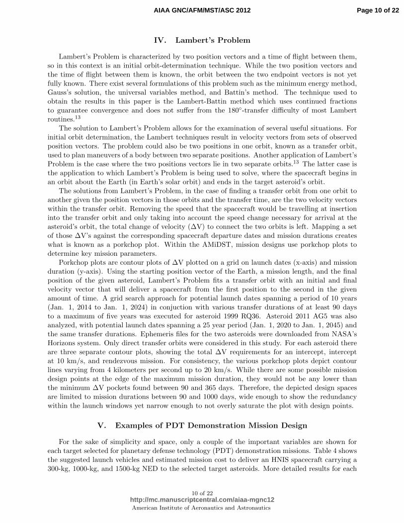
Asteroid 1999 RQ36 is the target of NASA’s OSIRIS-Rex Mission. Table 2 shows the asteroid’sreferenced orbital elements on March 14, 2012 and Figure 4 shows a depiction of the orbit inreference to the Solar System’s inner planets.
Table 2. Orbital Elements at Epoch 2456000.5 (March 14, 2012) of Asteroid 1999 RQ36.9
Element Symbol Value Units
Semi-Major Axis a 1.126038025838632 AU
Eccentricity e .2036994928473318
Inclination i 6.035405340360255 deg
Argument of Periapse ω 66.2666863129749 deg
Longitude of the Ascending Node Ω 2.051615098784052 deg
Mean Anomaly at Epoch M0 102.8657778912915 deg
Based on 1999 RQ36’s orbit being so close to the Earth, and small inclination from the Earth’sorbital plane, it is a very good target for study due to its low ∆V requirements. Astronomershave the chance to observe the asteroid every six years, when 1999 RQ36 comes close to the Earth.By the late 2000s, 1999 RQ36 was probably one of the best-studied near-Earth asteroids that hadnot been visited by spacecraft. The new observations of the asteroid will not only effect mission
7 of 22
American Institute of Aeronautics and Astronautics
Page 7 of 22
http://mc.manuscriptcentral.com/aiaa-mgnc12
AIAA GNC/AFM/MST/ASC 2012

Figure 4. Illustration of the orbit of asteroid 1999 RQ36 in reference to the inner planets.12
planning and development, but will directly address two key OSIRIS-Rex mission goals describedbelow.
The OSIRIS-Rex mission is the third mission selected for development as a part of NASA’s NewFrontiers Program, after New Horizons and Juno. OSIRIS-Rex is the first United States missionto bring samples from an asteroid back to Earth, and will increase our understanding of asteroidswhile possibly shedding new light on the origin of life on Earth. The target for the mission is 1999RQ36, the most accessible organic-rich asteroid from the early solar system.10
Another mission objective of NASA’s OSIRIS-Rex mission is to directly measure a small forcecalled the Yarkovsky effect. The Yarkovsky effect is defined as the force produced by asteroidsfrom the way they absorb and re-radiate the energy from the Sun in the form of heat. While theorbital perturbation caused by the propulsive force produced by this radiation of heat is small, onthe order of fractions of a kilometer per year, over a long enough period of time that persistentthrusting force can even transfer asteroids from the main belt to the inner solar system.11
Expected to launch in September 2016, OSIRIS-Rex would encounter 1999 RQ36 in October2019. After encounter, the spacecraft would globally map the surface of the asteroid for about ayear and a half and obtain at least 60 grams of sample surface material. The retrieved materialwould then return to Earth in September 2023 in a Stardust-heritage Sample Return Capsule(SRC). The samples in the SRC would then be delivered to NASA Johnsn Space Center (JSC)curation facility for distribution. Using an Atlas V 401 launch vehicle, OSIRIS-Rex would launchin September 2016 and undergo a deep-space manuever (DSM) in January 2017 before obtaining anEarth Gravity Assist (EGA) in September 2017 to aquire 1999 RQ36 in October 2019. This flightschedule encompasses the outbound cruise phase for the spacecraft. Asteroid operations would beconducted between October 2019 and March 2021, during which time the surface regolith will beobtained and the asteroid surface will be mapped. OSIRIS-Rex would depart 1999 RQ36 in March2021 and cruise until its sample return in late September 2023. Lockheed Martin is principallyresponsible for the building of the OSIRIS-Rex spacecraft. The total mission costs are estimatedto be $1.079 billion dollars, including the cost of the launch vehicle.12
8 of 22
American Institute of Aeronautics and Astronautics
Page 8 of 22
http://mc.manuscriptcentral.com/aiaa-mgnc12
AIAA GNC/AFM/MST/ASC 2012

Figure 5. Illustration of the orbit of asteroid 2011 AG5 in reference to Earth’s and Mars’ orbits.
Table 3. Orbital Elements at Epoch 2456200.5 (Sept. 20, 2012) of Asteroid 2011 AG5.9
Element Symbol Value Units
Semi-Major Axis a 1.430649648860713 AU
Eccentricity e .3901259169082548
Inclination i 3.680120116707978 deg
Argument of Periapse ω 53.51980424253686 deg
Longitude of the Ascending Node Ω 135.6872472400388 deg
Mean Anomaly at Epoch M0 320.0427907507387 deg
III.B. Asteroid 2011 AG5
Asteroid 2011 AG5 was discovered on January 8, 2011 as a part of the NASA-sponsored CatalinaSky Survey, a component of NASA’s Near-Earth Object Observation Program. Based on its av-erage albedo, 2011 AG5 has an estimated diameter of about 140 meters and a calculated impactprobability of 1-in-500 with an impact velocity of 15 kilometers per second relative to Earth onFebruary 5, 2040. For this NEO to impact the Earth in 2040, it would have to pass through a365 km wide keyhole during a close encounter with Earth on February 3, 2023. Even with theextended observation data arc spanning back to November 8, 2010, the uncertainty in 2011 AG5’sorbit allows for it to pass through a keyhole with a 1-in-500 chance. In the event that the asteroiddoes pass through the February 3, 2023 keyhole, 2011 AG5 will return on a 17:10 resonant returnorbit (17 Earth orbits to 10 asteroid orbits about the Sun) to impact the planet on February 5,2040. The orbital elements for 2011 AG5 are listed in Table 3 and the orbit diagram is shown inFigure 5.
More observations of 2011 AG5 are necessary to attempt to see whether the impact probabilityof the asteroid with Earth will decrease, especially since there is such limited observational data.Given the highly eccentric nature of the orbit, asteroid 2011 AG5 will complete one orbit in the timethat it would take Earth to complete a little more than an orbit and a half of its own, thereforemaking observations of the asteroid a bit more difficult and each encounter more important todiscerning orbital information. With such a small time period until 2011 AG5 may possibly impactthe Earth, it is essential to be planning for the chance that action must be taken to mitigate itsthreat.
9 of 22
American Institute of Aeronautics and Astronautics
Page 9 of 22
http://mc.manuscriptcentral.com/aiaa-mgnc12
AIAA GNC/AFM/MST/ASC 2012
IV. Lambert’s Problem
Lambert’s Problem is characterized by two position vectors and a time of flight between them,so in this context is an initial orbit-determination technique. While the two position vectors andthe time of flight between them is known, the orbit between the two endpoint vectors is not yetfully known. There exist several formulations of this problem such as the minimum energy method,Gauss’s solution, the universal variables method, and Battin’s method. The technique used toobtain the results in this paper is the Lambert-Battin method which uses continued fractionsto guarantee convergence and does not suffer from the 180-transfer difficulty of most Lambertroutines.13
The solution to Lambert’s Problem allows for the examination of several useful situations. Forinitial orbit determination, the Lambert techniques result in velocity vectors from sets of observedposition vectors. The problem could also be two positions in one orbit, known as a transfer orbit,used to plan maneuvers of a body between two separate positions. Another application of Lambert’sProblem is the case where the two positions vectors lie in two separate orbits.13 The latter case isthe application to which Lambert’s Problem is being used to solve, where the spacecraft begins inan orbit about the Earth (in Earth’s solar orbit) and ends in the target asteroid’s orbit.
The solutions from Lambert’s Problem, in the case of finding a transfer orbit from one orbit toanother given the position vectors in those orbits and the transfer time, are the two velocity vectorswithin the transfer orbit. Removing the speed that the spacecraft would be travelling at insertioninto the transfer orbit and only taking into account the speed change necessary for arrival at theasteroid’s orbit, the total change of velocity (∆V) to connect the two orbits is left. Mapping a setof those ∆V’s against the corresponding spacecraft departure dates and mission durations createswhat is known as a porkchop plot. Within the AMiDST, mission designs use porkchop plots todetermine key mission parameters.
Porkchop plots are contour plots of ∆V plotted on a grid on launch dates (x-axis) and missionduration (y-axis). Using the starting position vector of the Earth, a mission length, and the finalposition of the given asteroid, Lambert’s Problem fits a transfer orbit with an initial and finalvelocity vector that will deliver a spacecraft from the first position to the second in the givenamount of time. A grid search approach for potential launch dates spanning a period of 10 years(Jan. 1, 2014 to Jan. 1, 2024) in conjuction with various transfer durations of at least 90 daysto a maximum of five years was executed for asteroid 1999 RQ36. Asteroid 2011 AG5 was alsoanalyzed, with potential launch dates spanning a 25 year period (Jan. 1, 2020 to Jan. 1, 2045) andthe same transfer durations. Ephemeris files for the two asteroids were downloaded from NASA’sHorizons system. Only direct transfer orbits were considered in this study. For each asteroid thereare three separate contour plots, showing the total ∆V requirements for an intercept, interceptat 10 km/s, and rendezvous mission. For consistency, the various porkchop plots depict contourlines varying from 4 kilometers per second up to 20 km/s. While there are some possible missiondesign points at the edge of the maximum mission duration, they would not be any lower thanthe minimum ∆V pockets found between 90 and 365 days. Therefore, the depicted design spacesare limited to mission durations between 90 and 1000 days, wide enough to show the redundancywithin the launch windows yet narrow enough to not overly saturate the plot with design points.
V. Examples of PDT Demonstration Mission Design
For the sake of simplicity and space, only a couple of the important variables are shown foreach target selected for planetary defense technology (PDT) demonstration missions. Table 4 showsthe suggested launch vehicles and estimated mission cost to deliver an HNIS spacecraft carrying a300-kg, 1000-kg, and 1500-kg NED to the selected target asteroids. More detailed results for each
10 of 22
American Institute of Aeronautics and Astronautics
Page 10 of 22
http://mc.manuscriptcentral.com/aiaa-mgnc12
AIAA GNC/AFM/MST/ASC 2012

Table 4. Preferred launch vehicles to be used for PDT demonstration missions and estimated mission costsfor 300 kg NED/1000 kg NED/1500 kg NED HNIS spacecraft.
Target NEO Launch Vehicle Estimated Mission Cost ($)
Delta IV Medium 762.20M2003 GA Atlas V 431 1322.53M
Atlas V 551 1694.24M
Atlas V 401 770.52M2006 SJ198 Delta IV Heavy 1495.51M
NP NP
Delta IV Medium 762.20M2009 TB3 Atlas V 431 1322.53M
Delta IV Heavy 1797.36M
Delta IV Medium 762.20M2007 FS35 Atlas V 431 1322.53M
Atlas V 551 1694.24M
Delta IV M+(4,2) 770.52M2003 QC Delta IV Heavy 1495.51M
NP NP
Delta IV M+(4,2) 770.52M2004 GY Atlas V 551 1392.39M
NP NP
Delta IV Medium 762.20M2001 SX269 Atlas V 431 1322.53M
Atlas V 551 1694.24M
Delta IV Medium 762.20M1998 SB15 Atlas V 431 1322.53M
Atlas V 551 1694.24M
Delta IV M+(4,2) 770.52M2004 KE1 /Delta IV Heavy 1495.51M
NP NP
Delta IV Medium 762.20M2011 BX10 Atlas V 431 1322.53M
Delta IV Heavy 1797.36M
of these missions can be found by running the AMiDST program and selecting the pre-determinedtarget list for analysis. In some instances, the resulting launch vehicle and cost is listed as NP,standing for “not possible”, because given the total mass of the HNIS, target asteroid, departuredate, transfer duration, and total departure ∆V combination none of the currently existing launchvehicles can place the spacecraft into the 0-revolution direct transfer orbit necessary to meet therequired criteria. That is not to say that a mission to these target asteroids is impossible, becauseit can clearly be seen that with a less massive spacecraft a mission can be designed for any of thegiven NEOs. At least one of the mission criteria would have to be altered for a succesful mission,giving rise to the ability to create a custom mission to any given asteroid.
VI. Asteroid 1999 RQ36 Mission Design Example
VI.A. Rendezvous Mission Design
With the potential impact between Earth and 1999 RQ36 occurring in the late 22nd century, thereis plenty of time to perform a scientific mission to RQ36 such as NASA’s OSIRIS-Rex, to studythe asteroid’s composition and orbit for example, before having to resort to a deflection mission tomitigate the asteroid’s threat to Earth.
Without a specially designated spacecraft type for rendezvous missions, the general type ofspacecraft used during the analysis would be an Orbiter, meaning that the main piece of information
11 of 22
American Institute of Aeronautics and Astronautics
Page 11 of 22
http://mc.manuscriptcentral.com/aiaa-mgnc12
AIAA GNC/AFM/MST/ASC 2012
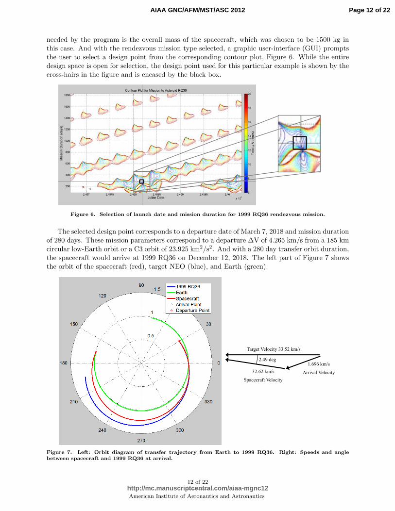
needed by the program is the overall mass of the spacecraft, which was chosen to be 1500 kg inthis case. And with the rendezvous mission type selected, a graphic user-interface (GUI) promptsthe user to select a design point from the corresponding contour plot, Figure 6. While the entiredesign space is open for selection, the design point used for this particular example is shown by thecross-hairs in the figure and is encased by the black box.
Figure 6. Selection of launch date and mission duration for 1999 RQ36 rendezvous mission.
The selected design point corresponds to a departure date of March 7, 2018 and mission durationof 280 days. These mission parameters correspond to a departure ∆V of 4.265 km/s from a 185 kmcircular low-Earth orbit or a C3 orbit of 23.925 km2/s2. And with a 280 day transfer orbit duration,the spacecraft would arrive at 1999 RQ36 on December 12, 2018. The left part of Figure 7 showsthe orbit of the spacecraft (red), target NEO (blue), and Earth (green).
Target Velocity 33.52 km/s
2.49 deg
32.62 km/s
Spacecraft Velocity
1.696 km/s
Arrival Velocity
Figure 7. Left: Orbit diagram of transfer trajectory from Earth to 1999 RQ36. Right: Speeds and anglebetween spacecraft and 1999 RQ36 at arrival.
12 of 22
American Institute of Aeronautics and Astronautics
Page 12 of 22
http://mc.manuscriptcentral.com/aiaa-mgnc12
AIAA GNC/AFM/MST/ASC 2012
At the time of rendezvous, the spacecraft will be encountering at a 2.49 degree angle. At thatpoint in time, 1999 RQ36’s velocity will be 33.52 km/s while the spacecraft’s would be about 32.6km/s. Relative to the asteroid, the spacecraft would have to gain almost 1.7 km/s of additionalspeed to match the asteroid’s speed, implying that part of the 1500 kg spacecraft mass would be apropulsion system capable of imparting the necessary ∆V. All this information is relatively uselessunless there is a suitable launch vehicle capable of putting the aforementioned spacecraft into orbit.The AMiDST analyzes several configurations of Delta II, Delta IV, and Atlas V launch vehicles tofind the most cost-efficient launch vehicle capable of successfully completing the desired mission.The resulting launch vehicle best suited for this mission is deemed to be a Delta IV Medium. Theassociated mission parameters are listed in Table 5. Estimated mission costs are evaluated based on
Table 5. Mission design parameters for rendezvous with Asteroid 1999 RQ36.
Mission Parameter Value
Asteroid 1999 RQ36
Asteroid Mass (kg) 1.4E+11
LEO altitude (km) 185
Spacecraft Designation Orbiter
Satellite Mass (kg) 1500
Departure ∆V (km/s) 4.265
C3 (km2/s2) 23.925
Launch Vehicle Delta IV Medium
Departure Date March 7, 2018
Mission Duration (days) 280
Arrival Angle (deg) 2.4925
Arrival Velocity (km/s) 1.696
Arrival Date December 12, 2018
Estimated Mission Cost ($) 748.809M
the same algorithm established in the Pre-Mission Design Algorithm. The mission cost is brokenup into three components: (1) the cost to fabricate the spacecraft, based on its mass compared tosimilar spacecraft costs, (2) the current cost of the chosen launch vehicle, and (3) a 30% marginadded in for mission operations cost and miscellaneous expenditures - summed together to get thefinal figure. The price attached to the mission is considered to be an upper-bound due to the addedmargin, but due to the uncertainty in these mission designs, the estimated mission cost should onlybe seen as an estimate. For the above case study, the estimated mission comes out to be nearly$750M to manufacture the 1500-kg spacecraft, purchase a Delta IV Medium launch vehicle, andconduct various mission operations.
It can be noted that the design point for the OSIRIS-Rex mission does not appear in therendezvous contour map. Given that the current study is limited to 0-revolution direct transfers,and OSIRIS-Rex is a multi-revolution mission that will have an Earth fly-by before encountering1999 RQ36, the OSIRIS-Rex mission design has not been duplicated. However, it can be seen thatthere are comparable alternative missions to NASA’s latest scientific endeavour.
VI.B. HNIS Disruption Mission Design
As an extension to the HNIS mission designs conducted at the ADRC in the past, an HNIS disrup-tion mission to asteroid 1999 RQ36 was conducted using the AMiDST. Due to 1999 RQ36’s large
13 of 22
American Institute of Aeronautics and Astronautics
Page 13 of 22
http://mc.manuscriptcentral.com/aiaa-mgnc12
AIAA GNC/AFM/MST/ASC 2012

mass and size, the chosen HNIS configuration is the 1500 kg NED spacecraft. In this configuration,the HNIS has a 670 kg impactor and a 3550 kg follower carrying a 1500 kg NED. With the space-craft configuration and mission type coordinated, the AMiDST proceeds to load the appropriatecontour plot for the user to pick the desired design point. The cross-hairs and black box on Figure 8show the region from which the design point was chosen from.
Figure 8. Selection of launch date and mission duration for 1999 RQ36 disruption mission.
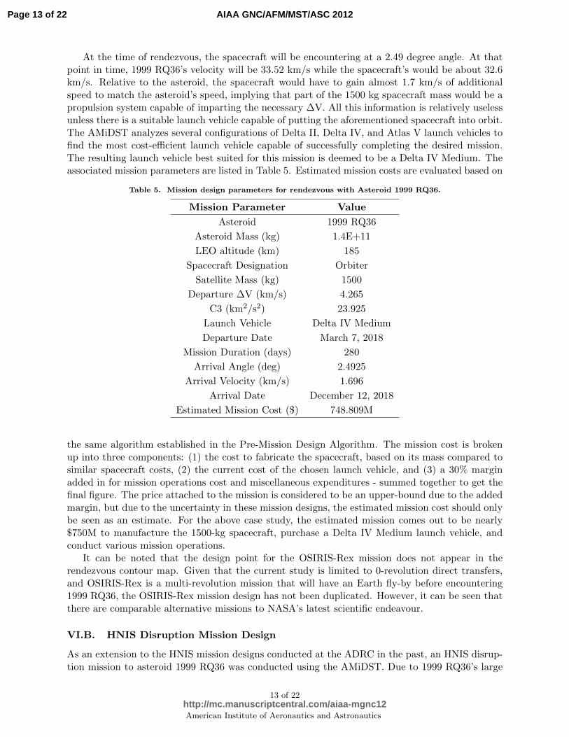
The selected design point for this HNIS disruption mission is chosen to occur at a late launchdate within the 10 year time period. The desired launch date comes out to be December 6, 2022with a mission duration of 233 days. Given the launch date and mission duration pair, the resultingdeparture ∆V from the 185-km circular low-Earth orbit is just over 4 km/s. From these missionparameters, the spacecraft’s trajectory is plotted in red along with the Earth’s path (green line)and 1999 RQ36’s trajectory (blue line) over the mission timespan in Figure 9 on the left. The HNISwould depart from Earth (red triangle) on December 6, 2022 and travel for 233 days until it wouldencounter the target NEO on July 27, 2023 (red circle).
On the right side of Figure 9, there is a depiction of the arrival conditions for the HNIS withrespect to 1999 RQ36. Arriving at 1999 RQ36 on July 27, 2023 the HNIS would be travellingat about 26.5 km/s at a 16.1 degree angle to the target NEO’s 28.7 km/s velocity, resulting inabout an 8-km/s velocity difference, too large for a normal fusing system to survive at impact andconfirming the choice of the HNIS configuration. Thanks to the large spacecraft mass and requireddeparture ∆V, the only launch vehicle capable of completing the given mission is the Delta IVHeavy. With such a powerful launch vehicle and massive spacecraft comes a large price tag as well,the estimated mission cost for this nuclear disruption mission is nearly $1.8B. Table 6 gives all thepertinent HNIS disruption mission parameters.
VII. Asteroid 2011 AG5 Mission Design Example
VII.A. Rendezvous Mission Design
Being such a recent discovery, asteroid 2011 AG5’s oribt is still relatively unknown. Based on whatis known about the asteroid’s orbit however indicates that there is relatively high impact probabilitywith the Earth, compared to other NEOs. Therefore, there is a need to better understand 2011AG5’s orbit so as to refine that impact probability. A rendezvous mission to the target NEO wouldbe one way to accomplish this task. A spacecraft of mass 1200 kg is chosen for this case study.
14 of 22
American Institute of Aeronautics and Astronautics
Page 14 of 22
http://mc.manuscriptcentral.com/aiaa-mgnc12
AIAA GNC/AFM/MST/ASC 2012
16.104 deg
Target Velocity 28.71 km/s
26.56 km/s
Spacecraft Velocity
8.03 km/s
Impact Velocity
Figure 9. Left: Orbit diagram of transfer trajectory from Earth to 1999 RQ36. Right: Speeds and anglebetween spacecraft and 1999 RQ36 at impact.
Table 6. Mission design parameters for intercept with Asteroid 1999 RQ36.
Mission Parameter Value
Asteroid 1999 RQ36
Asteroid Mass (kg) 1.4E+11
LEO altitude (km) 185
Spacecraft Designation HNIS
NED Mass (kg) 1500
Impactor Mass (kg) 670
Follower Mass (kg) 3550
Total HNIS Mass (kg) 5720
Departure ∆V (km/s) 4.002
C3 (km2/s2) 17.669
Launch Vehicle Delta IV Heavy
Departure Date December 6, 2022
Mission Duration (days) 233
Arrival Angle (deg) 16.104
Impact Velocity (km/s) 8.03
Arrival Date July 27, 2023
Estimated Mission Cost ($) 1797.66M
Together with the rendezvous mission type, a launch date and mission duration are chosen fromthe rendezvous contour plot for asteroid 2011 AG5, Figure 10. The cross-hairs and black box in
15 of 22
American Institute of Aeronautics and Astronautics
Page 15 of 22
http://mc.manuscriptcentral.com/aiaa-mgnc12
AIAA GNC/AFM/MST/ASC 2012

the figure show the region of the grid where the design point was chosen from.
Figure 10. Selection of launch date and mission duration for 2011 AG5 rendezvous mission.
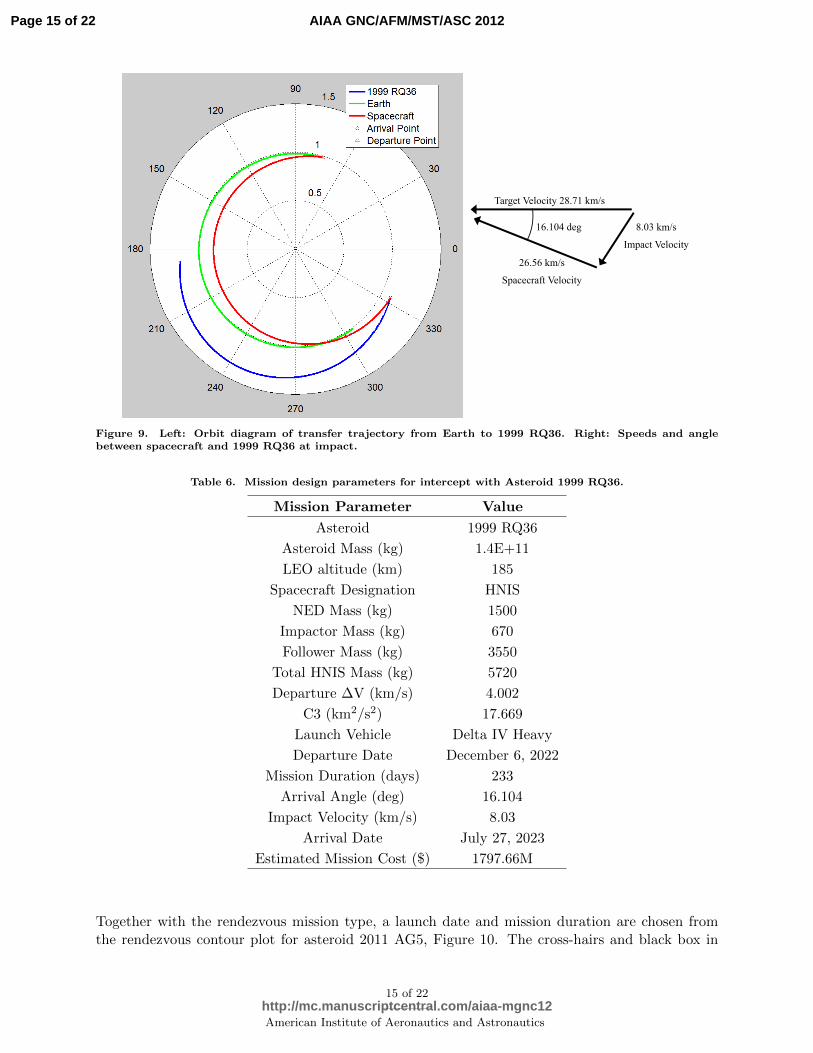
The chosen launch date and mission duration pair contains an April 29, 2028 launch date and280 day mission transfer time. The departure date comes from one of the more feasible launchwindows in the 25-year time frame. The launch window is wider than the window that opens inearly 2023, and is still early enough for an adequately long mission studying the asteroid, assessingits composition, size, and threat to planet Earth. The spacecraft would arrive at 2011 AG5 inFebraury 3, 2029, and could conduct proximity operations for a year or two before another decentlaunch window presents itself to launch a deflection mission if the asteroid’s threat is deemed greatenough to warrant action. On the left side of Figure 11 the transfer trajectory of the rendezvoussatellite, illustrated by the red line, is depicted from Earth, whose orbit during the transfer timeis shown in green, to the target NEO, portrayed by the blue line. The satellite’s departure andarrival points are represented by the red triangle and circle, respectively.
The right side of Figure 11 shows the terminal conditions of the spacecraft’s rendezvous withasteroid 2011 AG5. Since the spacecraft would be encountering the target NEO far from the Sun,the spacecraft would have more energy than the asteroid, requiring it to lose speed on approach toensure a successful capture. The given transfer trajectory conditions create a 6.32 degree arrivalangle between the target asteroid and spacecraft. At the end of the transfer trajectory the asteroidwould only be moving at about 16.7 km/s, while the spacecraft would be travelling approximately17.3 km/s, leaving the spacecraft to carry almost 2-km/s of ∆V to be used for braking purposes.
Despite the large departure ∆V of nearly 4.7 km/s, the spacecraft’s low mass allows for a smallerlaunch vehicle to complete the mission design, saving the mission a considerable amount of cost.The launch vehicle deemed most appropriate for this 2011 AG5 rendezvous mission is the DeltaIV Medium. As a whole, this mission comes out to be relatively cheap compared to the previousmission designs, estimated to cost a little over $655M. A brief summary of the important missiondesign parameters are given in Table 7.
VII.B. HNIS Disruption Mission Design
If asteroid 2011 AG5 were deemed a realistic threat to the survival of the planet, a deflection/disruptionmission would need to be launched. An important thing to remember when selecting a launch datefor a deflection/disruption mission to a target NEO is to give plenty of time for the perturbedasteroid or asteroid debris to settle into its/their new orbit(s). Again, an HNIS design is used for
16 of 22
American Institute of Aeronautics and Astronautics
Page 16 of 22
http://mc.manuscriptcentral.com/aiaa-mgnc12
AIAA GNC/AFM/MST/ASC 2012
Target Velocity 16.67 km/s
6.32 deg
17.30 km/s
Spacecraft Velocity
1.975 km/s
Arrival
Velocity
Figure 11. Left: Orbit diagram of transfer trajectory from Earth to 2011 AG5. Right: Speeds and anglebetween spacecraft and 2011 AG5 at arrival.
Table 7. Mission design parameters for rendezvous with Asteroid 2011 AG5.
Mission Parameter Value
Asteroid 2011 AG5
Asteroid Mass (kg) 4.1E+9
LEO altitude (km) 185
Spacecraft Designation Kinetic Impactor
Satellite Mass (kg) 1200
Departure ∆V (km/s) 4.668
C3 (km2/s2) 33.82
Launch Vehicle Delta IV Medium
Departure Date April 29, 2028
Mission Duration (days) 280
Arrival Angle (deg) 6.32
Arrival Velocity (km/s) 1.975
Arrival Date February 3, 2029
Estimated Mission Cost ($) 655.357M
this particular disruption mission case study. Figure 12 shows the contour plot for a direct interceptmission with 2011 AG5. The cross-hairs and black box in the diagram show where the design pointwhich is used to design the disruption mission. The current direct intercept mission case study hasa departure date April 15, 2027 and a mission duration of 350 days.
With nearly a full year of transit time, the HNIS would not arrive to the target NEO untilMarch 30, 2028, about 12 years before the estimated impact date. The orbit plot on the left of
17 of 22
American Institute of Aeronautics and Astronautics
Page 17 of 22
http://mc.manuscriptcentral.com/aiaa-mgnc12
AIAA GNC/AFM/MST/ASC 2012

Figure 12. Selection of launch date and mission duration for 2011 AG5 disruption mission.
Figure 13 shows the impact between the HNIS and the target to occur inside the Earth’s orbitalradius. The spacecraft will depart from Earth on April 15, 2027, represented by the red triangle,and travel for 350 days until its encounter with asteroid 2011 AG5 on March 30, 2028, shown asthe red circle. The spacecraft, asteroid, and Earth’s orbits are depicted by the red, blue, and greenlines, respectively.
14.277 deg
Target Velocity 36.47 km/s
33.276 km/s
Spacecraft Velocity
9.231 km/s
Impact Velocity
Figure 13. Left: Orbit diagram of transfer trajectory from Earth to 2011 AG5. Right: Speeds and anglebetween spacecraft and 2011 AG5 at impact.
The right side of Figure 13 shows the anticipated encounter between the HNIS and target NEO.Arrival at 2011 AG5 from the given trajectory will result in an impact angle of about 14.3 degrees.Such an arrival angle results in a relative velocity between the asteroid and the HNIS of over 9km/s. High relative impact velocities, similar to the one present in this mission, are the reasons
18 of 22
American Institute of Aeronautics and Astronautics
Page 18 of 22
http://mc.manuscriptcentral.com/aiaa-mgnc12
AIAA GNC/AFM/MST/ASC 2012
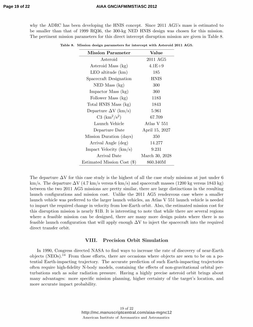
why the ADRC has been developing the HNIS concept. Since 2011 AG5’s mass is estimated tobe smaller than that of 1999 RQ36, the 300-kg NED HNIS design was chosen for this mission.The pertinent mission parameters for this direct intercept disruption mission are given in Table 8.
Table 8. Mission design parameters for intercept with Asteroid 2011 AG5.
Mission Parameter Value
Asteroid 2011 AG5
Asteroid Mass (kg) 4.1E+9
LEO altitude (km) 185
Spacecraft Designation HNIS
NED Mass (kg) 300
Impactor Mass (kg) 360
Follower Mass (kg) 1183
Total HNIS Mass (kg) 1843
Departure ∆V (km/s) 5.961
C3 (km2/s2) 67.709
Launch Vehicle Atlas V 551
Departure Date April 15, 2027
Mission Duration (days) 350
Arrival Angle (deg) 14.277
Impact Velocity (km/s) 9.231
Arrival Date March 30, 2028
Estimated Mission Cost ($) 860.340M
The departure ∆V for this case study is the highest of all the case study missions at just under 6km/s. The departure ∆V (4.7 km/s versus 6 km/s) and spacecraft masses (1200 kg versus 1843 kg)between the two 2011 AG5 missions are pretty similar, there are large distinctions in the resultinglaunch configurations and mission cost. Unlike the 2011 AG5 rendezvous case where a smallerlaunch vehicle was preferred to the larger launch vehicles, an Atlas V 551 launch vehicle is neededto impart the required change in velocity from low-Earth orbit. Also, the estimated mission cost forthis disruption mission is nearly $1B. It is interesting to note that while there are several regionswhere a feasible mission can be designed, there are many more design points where there is nofeasible launch configuration that will apply enough ∆V to inject the spacecraft into the requireddirect transfer orbit.
VIII. Precision Orbit Simulation
In 1990, Congress directed NASA to find ways to increase the rate of discovery of near-Earthobjects (NEOs).14 From those efforts, there are occasions where objects are seen to be on a po-tential Earth-impacting trajectory. The accurate prediction of such Earth-impacting trajectoriesoften require high-fidelity N-body models, containing the effects of non-gravitational orbital per-turbations such as solar radiation pressure. Having a highly precise asteroid orbit brings aboutmany advantages: more specific mission planning, higher certainty of the target’s location, andmore accurate impact probability.
19 of 22
American Institute of Aeronautics and Astronautics
Page 19 of 22
http://mc.manuscriptcentral.com/aiaa-mgnc12
AIAA GNC/AFM/MST/ASC 2012
VIII.A. Orbit Simulation
The orbital motion of an asteroid is governed by a so-called Standard Dynamical Model (SDM) ofthe form14
d2~r
dt2= − µ
r3~r +
n∑k=1
µk
(~rk − ~r|~rk − ~r|3
− ~rkr3k
)+ ~f (1)
where µ = GM is the gravitational parameter of the Sun, n is the number of perturbing bodies,µk and ~rk are the gravitational parameter and heliocentric position vector of perturbing body k,respectively, and ~f represents other non-conservative orbital perturbation acceleration.
Previous studies performed at the ADRC were concerned with the impact probability of po-tential Earth-impacting asteroids, such as 99942 Apophis. Using commercial software such asNASA’s General Mission Analysis Tool (GMAT), AGI’s Satellite Tool Kit (STK), and Jim Baer’sComet/asteroid Orbit Determination and Ephemeris Software (CODES), the ADRC conductedprecision orbital simulation studies to compare with JPL’s Sentry program.15
VIII.B. Current Work and Capabilities
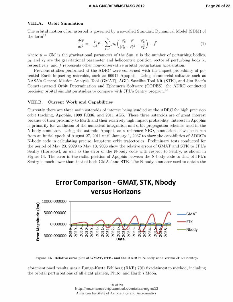
Currently there are three main asteroids of interest being studied at the ADRC for high precisionorbit tracking, Apophis, 1999 RQ36, and 2011 AG5. These three asteroids are of great interestbecause of their proximity to Earth and their relatively high impact probability. Interest in Apophisis primarily for validation of the numerical integration and orbit propagation schemes used in theN-body simulator. Using the asteroid Apophis as a reference NEO, simulations have been runfrom an initial epoch of August 27, 2011 until January 1, 2037 to show the capabilities of ADRC’sN-body code in calculating precise, long-term orbit trajectories. Preliminary tests conducted forthe period of May 23, 2029 to May 13, 2036 show the relative errors of GMAT and STK to JPL’sSentry (Horizons), as well as the error of the N-body code with respect to Sentry, as shown inFigure 14. The error in the radial position of Apophis between the N-body code to that of JPL’sSentry is much lower than that of both GMAT and STK. The N-body simulator used to obtain the
-5000.000000
0.000000
5000.000000
10000.000000
2029-…
2029-…
2030-…
2030-…
2030-…
2031-…
2031-…
2031-…
2032-…
2032-…
2033-…
2033-…
2033-…
2034-…
2034-…
2034-…
2035-…
2035-…
2035-…
Erro
r M
agn
itu
de
(km
)
Date
Error Comparison - GMAT, STK, Nbody versus Horizons
GMAT
STK
Nbody
-5000.000000
0.000000
5000.000000
10000.000000
2029-…
2029-…
2030-…
2030-…
2030-…
2031-…
2031-…
2031-…
2032-…
2032-…
2033-…
2033-…
2033-…
2034-…
2034-…
2034-…
2035-…
2035-…
2035-…
Erro
r M
agn
itu
de
(km
)
Date
Error Comparison - GMAT, STK, Nbody versus Horizons
GMAT
STK
Nbody
Figure 14. Relative error plot of GMAT, STK, and the ADRC’s N-body code versus JPL’s Sentry.
aforementioned results uses a Runge-Kutta Fehlberg (RKF) 7(8) fixed-timestep method, includingthe orbital perturbations of all eight planets, Pluto, and Earth’s Moon.
20 of 22
American Institute of Aeronautics and Astronautics
Page 20 of 22
http://mc.manuscriptcentral.com/aiaa-mgnc12
AIAA GNC/AFM/MST/ASC 2012

IX. Future Work
Work is being done to expand the numerical integration scheme used for the N-body simulatorfrom the current RKF7(8) method to an Adams-Bashforth variable timestep numerical integrationscheme. The Runge-Kutta-Fehlberg method is used for approximating the solution of a differentialequation x(t) = f(x,t) with initial condition x(t0) = c. The implementation evaluates f(x,t) thirteentimes per step using embedded seventh order and eight order Runge-Kutta estimates to estimatenot only the solution but also the error. The Adams-Bashforth numerical integrator solves theinitial value problem for stiff or nonstiff systems of first order Ordinary Differential Equations(ODEs). and incorporates the use of the Jacobian matrix df/dx to calculate the solution to thesystem at the next point in time.
In addition to the major planetary perturbations, non-gravitational orbital perturbations suchas solar radiation pressure and the Yarkovsky effect will be added into the pre-existing N-bodygravitation model in order to have a more encompassing dynamical model. With the introductionof such non-conservative forces the error within the system will increase, but the expected increasein orbital accuracy should out-weigh the benefits of leaving them out of the dynamical model. Amore complete dynamical model will allow the accurate calculation of asteroid impact probabilitiesand gravitational keyholes, leading to more effective mission designs.
With the multitude of variables to track and optimize in order to find the optimal designfor a mission to a target NEO, the use of a GPU based genetic algorithm will be utilized inconjuction with the AMiDST program to find the optimal mission design.16 Genetic algorithmsare a stochastic optimization method, which means that it requires no initial guess to find solutions.Through the use of a genetic algorithm, a pre-determined cost function would be able to evaluate therandomly generated and evolved solutions, taking into account the launch date, mission trajectory,transfer duration, launch vehicle, estimated mission cost, etc. all at once instead of component bycomponent, to arrive at the globally optimal solution.
X. Conclusion
In this paper, the various aspects of the Asteroid Mission Design Software Tool (AMiDST),which is being developed at the Iowa State ADRC, have been presented for preliminary missiondesigns of direct intercept and rendezvous of reference target NEOs, such as 1999 RQ36 and 2011AG5, as well as the accurate tracking of asteroid Apophis in long-term, N-body gravitationalsimulations. This paper has shown that the AMiDST is capable of accurately simulating the orbitof a body around the Sun, taking into account graviational perturbations of the eight planets,Pluto, and Earth’s Moon, as well as various designs for direct intercept and rendezvous missions toEarth-threating asteroids. Despite the odds of Earth being struck by an asteroid of sufficient sizeto worry about deflection missions to those threatening bodies, the day may come when the Earthis truly in danger. When that day arises, software tools like the one described in this paper canprovide a first-order approximation and critical knowledge that can be pivotal to the success of areal mission to a target NEO.
Acknowledgments
This study was supported by the NIAC (NASA Innovative Advanced Concept) program of theNASA Office of the Chief Technologist and by the Iowa Space Grant Consortium. The authorswould like to thank the entire ADRC research group for their discussions and guidance in therefinement of this paper.
21 of 22
American Institute of Aeronautics and Astronautics
Page 21 of 22
http://mc.manuscriptcentral.com/aiaa-mgnc12
AIAA GNC/AFM/MST/ASC 2012
References
1Vardaxis, G., et al. “Conceptual Design of Planetary Defense Technology Demonstration Mission, AIAA 12-128,AAS/AIAA Space Flight Mechanics Meeting, February 2012.
2Pitz, A., et al. “A Hypervelocity Nuclear Interceptor System (HNIS) for Optimal Disruption of Near-EarthObjects,” AAIA 12-225, AAS/AIAA Space Flight Mechanics Meeting, February 2012.
3T. Winkler, et al. “Target Selection for a Planetary Defense Technology Demonstration Mission,” AAIA 12-226,AAS/AIAA Space Flight Mechanics Meeting, February 2012.
4Vardaxis, G., Pitz, A., and Wie, B., “Conceptual Design of Planetary Defense Technology DemonstrationMission, AAS 12 128, AAS/AIAA Space Flight Mechanics Meeting, Charleston, SC, Jan 30 Feb 2, 2012.
5Melamed, N., “Development of a handbook and an on-line tool on defending Earth against Potentially HazardousObjects”, Acta Astronautica (2012), http://dx.doi.org/10.1016/j.actaastro.2012.02.021.
6“LTTT Suite Optimization Tools.” LTTT Suite Optimization Tools. Ed. Timothy A.Reckart. NASA Glenn Research Center Space Science Projects Office, 23 Apr. 2012. < http ://microgravity.grc.nasa.gov/SSPO/ISPTProg/LTTT/ >.
7GMAT Design Team, “General Mission Analysis Tool (GMAT), < gmat.gsfc.nasa.gov/index.html >.8“Near-Earth Object Program.” Near-Earth Object Program. Ed. Donald K. Yeomans. National Aeronautics and
Space Administration.< http : //neo.jpl.nasa.gov/index.html >.9“JPL Solar System Dynamics.” JPL Solar System Dynamics. Ed. Donald K. Yeomans. NASA Jet Propulsion
Laboratory. < http : //ssd.jpl.nasa.gov/ >.10“National Aeronautics and Space Administration - Marshall Space Flight Center.” NEW
FRONTIERS Programs. Ed. Anthony Goodeill. Marshall Space Flight Center. < http ://discoverynewfrontiers.nasa.gov/missions/index.cfml >.
11Agle, D. C., “JPL News – NASA Scientists Use Radar to Detect Asteroid Force,” Space, Stars, Mars, Earth,Planets and More - NASA Jet Propulsion Laboratory. < http : //www.jpl.nasa.gov/releases/2003/163.cfm >.
12“The OSIRIS-REx Mission - An Asteroid Sample Return Mission.The OSIRIS-REx Mission - An AsteroidSample Return Mission. < http : //osiris− rex.lpl.arizona.edu/ >.
13Vallado, David A., and Wayne D. McClain. Fundamentals of Astrodynamics and Applications. Third ed.Hawthorne, CA: Microcosm, 2007. Print.
14Chodas, P. W. and Yeomans, D., “Orbit Determination and Estimation of Impact Probability for Near EarthObjects.” AAS 09-002.
15A. Pitz, et al. “Earth-Impact Probability Computation of Disrupted Asteroid Fragments UsingGMAT/STK/CODES, AAS 11-408, AAS/AIAA Astrodynamics Specialist Conference, August 2011.
16Wagner, S., Kaplinger, B., and Wie, B., “GPU Accelerated Genetic Algorithm for Multiple Gravity-Assist andImpulsive Delta-V Maneuvers,” presented at AIAA Astrodynamics Specialists Conference, August 2012.
22 of 22
American Institute of Aeronautics and Astronautics
Page 22 of 22
http://mc.manuscriptcentral.com/aiaa-mgnc12
AIAA GNC/AFM/MST/ASC 2012