astrosafe bg-series and kg-series containment housings
TRANSCRIPT
AstroSafe® BG-Series and KG-Series Containment Housings
(Gasket Seal Filter Housings for Bag-Out or Non-Bag-Out Applications)
2
TABLE OF CONTENTS
Important Message .................................3
Quality Assurance ...................................4
BG-Series Bag-In/Bag-Out Containment Housings ...........................6
Safety First ...............................................7
B-Series and K-Series Comparisons............................................8
Bag-In/Bag-Out Accessories .................9
Cinching Strap ......................................9
Bag-In/Bag-Out Accessories ...............9
Bagging Ring ........................................9
PVC Change-Out Bag ........................10
Change-Out Port ................................10
Security Strap .....................................10
Bag-In/Bag-Out Process ......................11
BG-Series and KG-Series: Standard Features .................................12
Housing Material and Finish, Smooth Inlet Design, Filter Access Doors ........12
Construction .......................................12
BG-Series and KG-Series: Gasket Seal Design ...............................13
Design Concept, Description ..............13
BG-Series and KG-Series: Standard Housing Filter Accommodations .........14
BG-Series and KG-Series Additional Housing Filter Accommodations .........16
Door Latches, Bag-In/Bag-Out Port, Filter Removal Rod ..............................16
Change-Out Accessories, Engraved ID Label ..............................17
Connections to Ductwork, Filter Locking Mechanism ...................17
Leak Testing ........................................18
BG-Series Containment Housing: Ordering Information .............................19
BG-Series Containment Housing: Suggested Specifications ....................21
KG-Series Gasket Seal Non-Bag-In/ Bag-Out Containment Housings .........23
Door Latches, Filter Locking Mechanism, Engraved ID Label ..........24
KG-Series Containment Housing: Ordering Information .............................25
KG-Series Containment Housing: Suggested Specifications ....................27
BG-Series and KG-Series Containment Housing: Available Options ..................29
Prefilter Sections, Magnehelic Gages ..............................30
Static Pressure Taps, Test Ports DOP, PAO or Freon, Swivel Door Latches ...............................................31
Weather Cap, Isolation Damper, Transitions ...........................................32
In-Place Test Housings, Bead Blast Finish, Scan Test Housing ..................33
Metal Door Pocket, Filter Removal Tray, Change-Out Equipment .............34
Banding Kit, Lifting Lugs .....................34
Moisture Drains and Valves.................34
Drilled Duct Connection Flanges, Drill Flanges ........................................35
BG-Series and KG-Series Containment Housing: General Design Considerations
Determining Door Access ...................36
Prefiltration, Particulate Filtration, Gas and Particulate Filtration,
Gas Phase Filtration, In-Place Test Sections ..............................................37
Seismic Qualifications, In-Place Efficiency Testing, In-Place Scan Testing, Vertical Flow Applications, Plenums, Transitions and Dampers ....................38
HEPA Filters, Prefilters, Adsorbers ......39
BG-Series and KG-Series Containment Housings .......................39
3
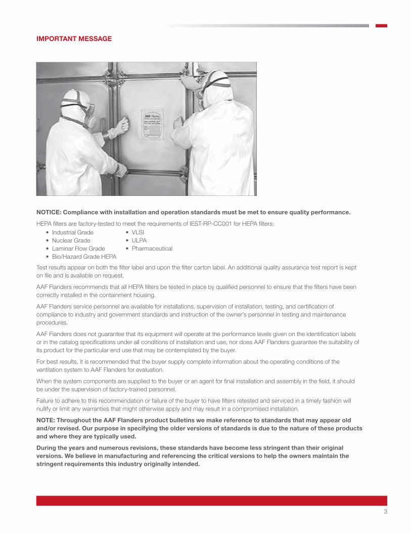
NOTICE: Compliance with installation and operation standards must be met to ensure quality performance.
HEPA filters are factory-tested to meet the requirements of IEST-RP-CC001 for HEPA filters: • Industrial Grade • Nuclear Grade • Laminar Flow Grade • Bio/Hazard Grade HEPA
Test results appear on both the filter label and upon the filter carton label. An additional quality assurance test report is kept on file and is available on request.
AAF Flanders recommends that all HEPA filters be tested in place by qualified personnel to ensure that the filters have been correctly installed in the containment housing.
AAF Flanders service personnel are available for installations, supervision of installation, testing, and certification of compliance to industry and government standards and instruction of the owner’s personnel in testing and maintenance procedures.
AAF Flanders does not guarantee that its equipment will operate at the performance levels given on the identification labels or in the catalog specifications under all conditions of installation and use, nor does AAF Flanders guarantee the suitability of its product for the particular end use that may be contemplated by the buyer.
For best results, it is recommended that the buyer supply complete information about the operating conditions of the ventilation system to AAF Flanders for evaluation.
When the system components are supplied to the buyer or an agent for final installation and assembly in the field, it should be under the supervision of factory-trained personnel.
Failure to adhere to this recommendation or failure of the buyer to have filters retested and serviced in a timely fashion will nullify or limit any warranties that might otherwise apply and may result in a compromised installation.
NOTE: Throughout the AAF Flanders product bulletins we make reference to standards that may appear old and/or revised. Our purpose in specifying the older versions of standards is due to the nature of these products and where they are typically used.
During the years and numerous revisions, these standards have become less stringent than their original versions. We believe in manufacturing and referencing the critical versions to help the owners maintain the stringent requirements this industry originally intended.
IMPORTANT MESSAGE
• VLSI • ULPA • Pharmaceutical
4
Quality Assurance Program
AAF Flanders established the Quality Assurance program to address the 18 criteria structure of ASME NQA-1 (formally N45.2), “Quality Assurance Requirements for Nuclear Facility Applications.” As suppliers of High Efficiency Air Filtration products and services, there are three standards that govern the majority of AAF Flanders’ activities.
1. ASME N509-1989 (reaffirmed 1996) “Nuclear Power Plant Air-cleaning Units and Components”
2. ASME N510-1989 (reaffirmed 1995) “Testing of Nuclear Air Treatment Systems”
3. ASME AG-1 latest revision “Code on Nuclear Air and Gas Treatment”
These standards and our customer’s specifications invoke many other standards and codes the AAF Flanders’ Quality Assurance program incorporates as standard practice.
There are a variety of Quality Assurance programs that manufacturers implement to ensure product and service quality, two such systems are ISO-9001 and ASME NQA-1.
Abstracts of these programs include:
ISO 9001:2015 specifies requirements for a Quality Management System where an organization
1. Needs to demonstrate its ability to consistently provide product that meets customer and applicable regulatory requirements, and
2. Aims to enhance customer satisfaction through the effective application of the system, including processes for continual improvement of the system, and the assurance of conformity to customer and applicable regulatory requirements.
All requirements of this international standard are generic and are intended to be applicable to all organizations, regardless of type, size, and product provided.1
ASME NQA-1: This Standard sets forth requirements for the establishment and execution of quality assurance programs for the siting, design, construction, operation, and decommissioning of nuclear facilities. Non-mandatory guidance is provided in the Appendices. NQA-1 establishes 18 criteria covering all aspects of quality, from purchase of raw materials to design and testing.2
Because ASME NQA-1 applies to the Nuclear Industry where containment and safety are of paramount concern, it is generally seen to establish more checks and balances.
Containment air filtration started out as a critical requirement in the Nuclear industry to protect workers, the public, and the environment. Today, containment air filtration is a critical issue in a variety of industries and applications, from pharmaceutical, health care, military, and the original nuclear applications among others. Because of the critical safety requirements of the nuclear industry, ASME N509, ASME N510, and ASME AG-1 are recognized as the standards for design and testing of containment air filtration systems. Each of these standards requires a Quality Assurance program that meets the requirements of ASME NQA-1.
AAF Flanders is certified to ISO 9001:2015 and maintains a full scope Quality Assurance program that meets the requirements of ASME NQA-1, 10 CFR 50 Appendix B, and DOE O 414 1A. Customers that require the stringent application of quality principles that only a mature and developed program can offer routinely audit this Quality Assurance program.
Sources: 1. ISO.org 2. ASME.org 3. Comparison NQA 1 and ISO 9001 Technical Report, available from ASME.org
5
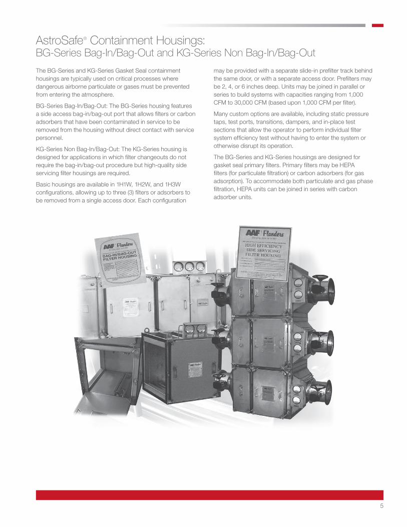
The BG-Series and KG-Series Gasket Seal containment housings are typically used on critical processes where dangerous airborne particulate or gases must be prevented from entering the atmosphere.
BG-Series Bag-In/Bag-Out: The BG-Series housing features a side access bag-in/bag-out port that allows filters or carbon adsorbers that have been contaminated in service to be removed from the housing without direct contact with service personnel.
KG-Series Non Bag-In/Bag-Out: The KG-Series housing is designed for applications in which filter changeouts do not require the bag-in/bag-out procedure but high-quality side servicing filter housings are required.
Basic housings are available in 1H1W, 1H2W, and 1H3W configurations, allowing up to three (3) filters or adsorbers to be removed from a single access door. Each configuration
AstroSafe® Containment Housings: BG-Series Bag-In/Bag-Out and KG-Series Non Bag-In/Bag-Out
may be provided with a separate slide-in prefilter track behind the same door, or with a separate access door. Prefilters may be 2, 4, or 6 inches deep. Units may be joined in parallel or series to build systems with capacities ranging from 1,000 CFM to 30,000 CFM (based upon 1,000 CFM per filter).
Many custom options are available, including static pressure taps, test ports, transitions, dampers, and in-place test sections that allow the operator to perform individual filter system efficiency test without having to enter the system or otherwise disrupt its operation.
The BG-Series and KG-Series housings are designed for gasket seal primary filters. Primary filters may be HEPA filters (for particulate filtration) or carbon adsorbers (for gas adsorption). To accommodate both particulate and gas phase filtration, HEPA units can be joined in series with carbon adsorber units.

6
The BG-Series bag-in/bag-out housing is a side servicing filter housing that has been designed to meet the air filtration needs of industries and research facilities that handle dangerous or toxic biological, radiological, or carcinogenic materials.
Once the initial filters are installed and the first bag attached, all filters, both dirty and new, are handled through the bag. These procedures are summarized on page 11.
Depending on the user’s requirements, the BG-Series housing may have an assortment of filter arrangements, including prefilters, HEPA filters, and carbon adsorbers. Regardless of
BG-Series Gasket Seal Bag-In/Bag-Out Containment Housings
System Configurations
Basic Housings
BG-Series Containment Housings
the type of filters contained within the BG-Series housing, the filter change-out procedure is the same. BG-Series housings are designed to accommodate standard gasket seal HEPA filters and carbon adsorbers.
Manufactured under stringent quality assurance controls, BG-Series housings are subjected to thorough inspections and leak tightness tests before leaving the factory, and are guaranteed to pass both DOP and/or Freon in-place tests. This guarantee is contingent upon the use of properly installed AAF Flanders HEPA filters and AAF Flanders adsorbers.
Access Doors
DownstreamTest Section
1H1W with SeparatePrefilter Door
Note: All housings are available with optional prefilter sections behind primary filter door or with a separate prefilter door.
1H1W 1H2W 1H3W
AdsorberSection
HEPAFilterSection
UpstreamTestSection
PrefilterSection
Access Doors
3H2W Housings consisting of Prefilters, Upstream Test Sections, HEPAs, Adsorbers, and Downstream Test Sections. ACCESS DOORS ON ONE SIDE ONLY.
3H4W Housings consisting of Two 3H2W Housings in parallel. ACCESS DOORS ON BOTH SIDES.
Air Flow
7
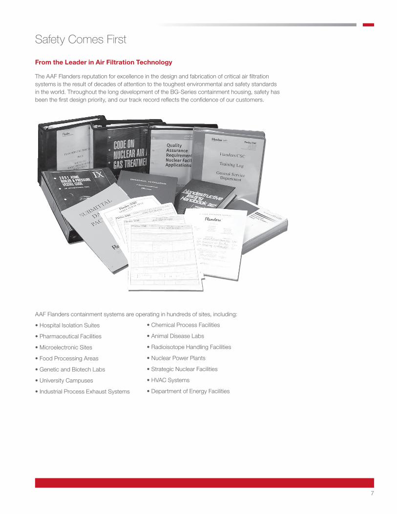
The AAF Flanders reputation for excellence in the design and fabrication of critical air filtration systems is the result of decades of attention to the toughest environmental and safety standards in the world. Throughout the long development of the BG-Series containment housing, safety has been the first design priority, and our track record reflects the confidence of our customers.
From the Leader in Air Filtration Technology
Safety Comes First
AAF Flanders containment systems are operating in hundreds of sites, including:
• Hospital Isolation Suites
• Pharmaceutical Facilities
• Microelectronic Sites
• Food Processing Areas
• Genetic and Biotech Labs
• University Campuses
• Industrial Process Exhaust Systems
• Chemical Process Facilities
• Animal Disease Labs
• Radioisotope Handling Facilities
• Nuclear Power Plants
• Strategic Nuclear Facilities
• HVAC Systems
• Department of Energy Facilities
8
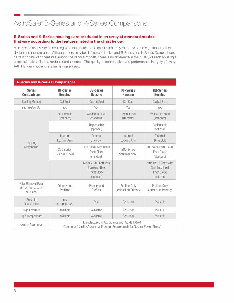
B-Series and K-Series housings are produced in an array of standard models that vary according to the features listed in the chart below.
All B-Series and K-Series housings are factory tested to ensure that they meet the same high standards of design and performance. Although there may be differences in size and B-Series and K-Series Comparisons certain construction features among the various models, there is no difference in the quality of each housing’s essential task to filter hazardous contaminants. The quality of construction and performance integrity of every AAF Flanders housing system is guaranteed.
AstroSafe® B-Series and K-Series Comparisons
B-Series and K-Series Comparisons
Series Comparisons
BF-Series Housing
BG-Series Housing
KF-Series Housing
KG-Series Housing
Sealing Method Gel Seal Gasket Seal Gel Seal Gasket Seal
Bag-In/Bag-Out Yes Yes Yes Yes
Locking Mechanism
Replaceable (standard)
Welded In Place (standard)
Replaceable (standard)
Welded In Place (standard)
Replaceable (optional)
Replaceable (optional)
Internal Locking Arm
External Drive Bolt
Internal Locking Arm
External Drive Bolt
300 Series Stainless Steel
300 Series with Brass Pivot Block (standard)
300 Series Stainless Steel
300 Series with Brass Pivot Block (standard)
Nitronic 60 Shaft with Stainless Steel
Pivot Block (optional)
Nitronic 60 Shaft with Stainless Steel
Pivot Block (optional)
Filter Removal Rods (for 2- and 3-wide
housings)
Primary and Prefilter
Primary and Prefilter
Prefilter Only (optional on Primary)
Prefilter Only (optional on Primary)
Seismic Qualification
Yes (see page 38)
Yes Available Available
High Pressure Available Available Available Available
High Temperature Available Available Available Available
Quality AssuranceManufactured in Accordance with ASME NQA-1
Assurance “Quality Assurance Program Requirements for Nuclear Power Plants”

9
Cinching Strap
A cinching strap is provided with each bag to tie off the slack in the bag during the interval between filter changes. The cinching strap prevents the bag from being drawn into the housing during normal operations. The strap is tied at a point near the tip of the bag-in/bag-out port, drawing the bag tightly across the port and allowing the slack to fall off to the outside.
Bag-In/Bag-Out Accessories
If provided, the prefilters, HEPA filters, and carbon adsorbers are shipped separately. Additionally, bags, straps, and instruction manuals are shipped in the accessory box, separate from the housing.
Bagging Ring
The bagging ring is seal-welded around the access port of each BG-Series containment housing. The elastic shock cord of the PVC change-out bag is stretched around the bagging ring. The BG-Series bagging ring features a hemmed edge to prevent tearing the bag, and two (2) continuous ribs to secure the bag.
BG-Series Containment Housing: Bag-In/Bag-Out Accessories
Second Rib
Bagging Ring First Ring
Hemmed Edge
Bag
Shock Cord
Housing
Security Strap
PVC Bagging Ring
10
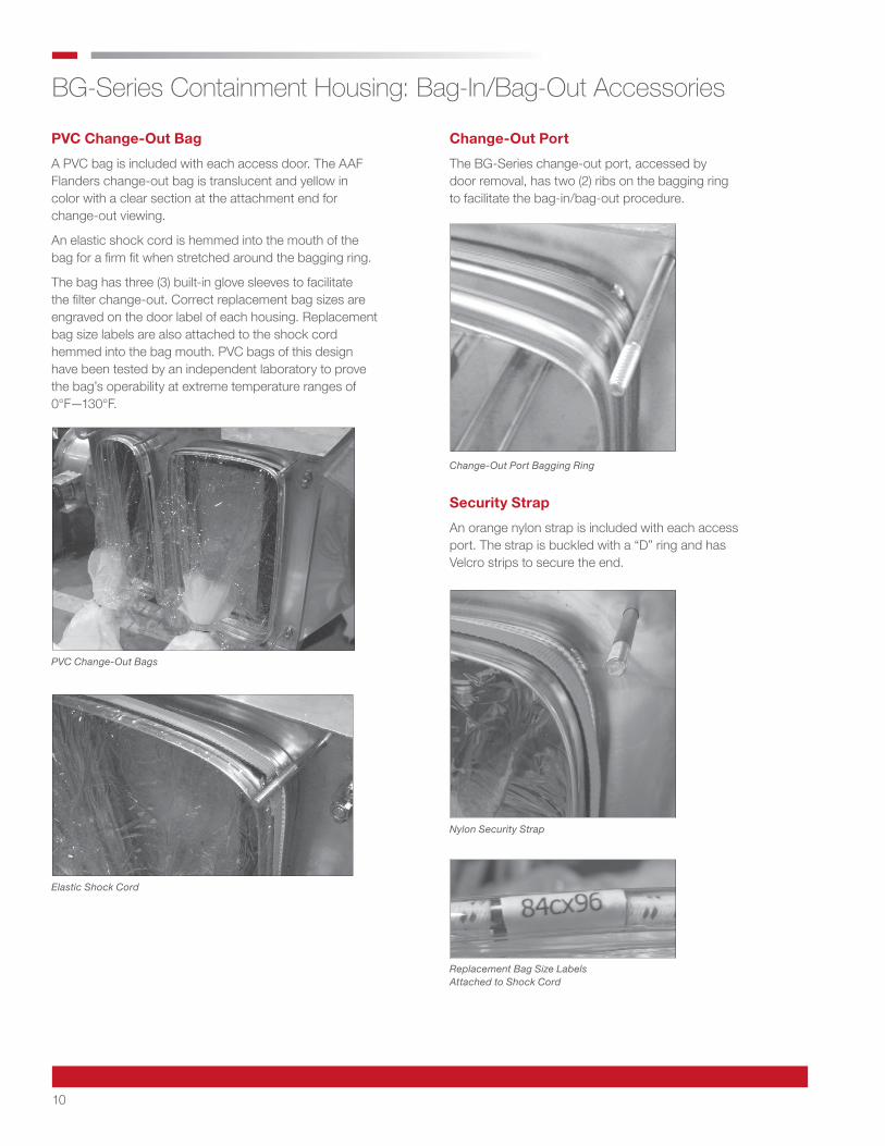
PVC Change-Out Bag
A PVC bag is included with each access door. The AAF Flanders change-out bag is translucent and yellow in color with a clear section at the attachment end for change-out viewing.
An elastic shock cord is hemmed into the mouth of the bag for a firm fit when stretched around the bagging ring.
The bag has three (3) built-in glove sleeves to facilitate the filter change-out. Correct replacement bag sizes are engraved on the door label of each housing. Replacement bag size labels are also attached to the shock cord hemmed into the bag mouth. PVC bags of this design have been tested by an independent laboratory to prove the bag’s operability at extreme temperature ranges of 0°F—130°F.
Change-Out Port
The BG-Series change-out port, accessed by door removal, has two (2) ribs on the bagging ring to facilitate the bag-in/bag-out procedure.
Security Strap
An orange nylon strap is included with each access port. The strap is buckled with a “D” ring and has Velcro strips to secure the end.
BG-Series Containment Housing: Bag-In/Bag-Out Accessories
PVC Change-Out Bags
Elastic Shock Cord
Change-Out Port Bagging Ring
Nylon Security Strap
Replacement Bag Size Labels Attached to Shock Cord
11
HEPA FilterHEPA Filter
HEPA Filter HEPA Filter HEPA Filter
Ribbed Bagging Ring
Flanges for Dust Connection
Knife Edge Primary Filter Removal Rod
Locking Arm
Filter Handling Glove Sleeves (Typ. 3)
Cinching Strap
Door Gasket
Access Door
Change-Out Bag (PVC)
Security Strap
HEPA Filter or Adsorber
Door Knob
Door Label
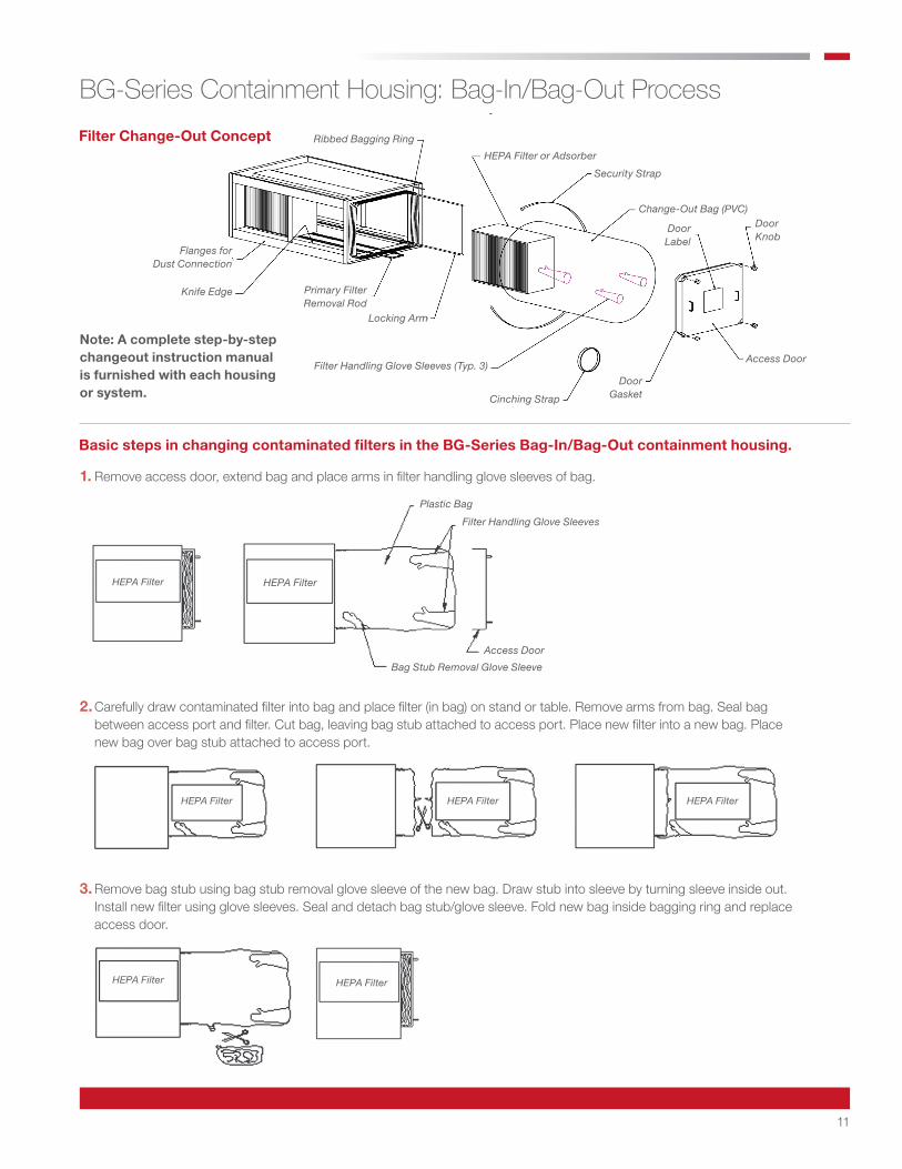
Note: A complete step-by-step changeout instruction manual is furnished with each housing or system.
BG-Series Containment Housing: Bag-In/Bag-Out Process
Filter Change-Out Concept
1. Remove access door, extend bag and place arms in filter handling glove sleeves of bag.
2. Carefully draw contaminated filter into bag and place filter (in bag) on stand or table. Remove arms from bag. Seal bag between access port and filter. Cut bag, leaving bag stub attached to access port. Place new filter into a new bag. Place new bag over bag stub attached to access port.
3. Remove bag stub using bag stub removal glove sleeve of the new bag. Draw stub into sleeve by turning sleeve inside out. Install new filter using glove sleeves. Seal and detach bag stub/glove sleeve. Fold new bag inside bagging ring and replace access door.
Basic steps in changing contaminated filters in the BG-Series Bag-In/Bag-Out containment housing.
HEPA Filter
Plastic Bag
Filter Handling Glove Sleeves
Access Door
Bag Stub Removal Glove Sleeve
HEPA Filter
12
BG-Series Containment Housing: Standard Features
Housing Material and Finish
Materials are unpainted 14 and 11 gauge Type 304 stainless steel, with a 2B finish. Housing welded joints and seams are wire brushed and/ or buffed to remove heat discoloration, burrs, and sharp edges.
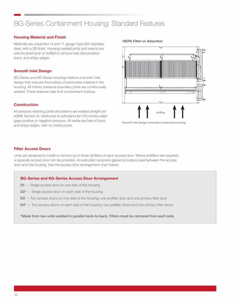
Smooth Inlet Design
BG-Series and KG-Series housings feature a smooth inlet design that reduces the buildup of particulate material in the housing. All interior pressure boundary joints are continuously welded. These features help limit contaminant buildup.
Construction
All pressure retaining joints and seams are welded airtight per ASME Section IX, reinforced to withstand ten (10) inches water gage positive or negative pressure. All welds are free of burrs and sharp edges, with no visible pores.
Filter Access Doors
Units are designed to install or remove up to three (3) filters at each access door. Where prefilters are required, a separate access door can be provided. An extruded neoprene gasket provides a seal between the access door and the housing. See the access door arrangement chart below:
BG-Series and KG-Series Access Door Arrangement
D1 — Single access door on one side of the housing
D2* — Single access door on each side of the housing
D3 — Two access doors on one side of the housing: one prefilter door and one primary filter door
D4* — Two access doors on each side of the housing: two prefilter doors and two primary filter doors
*Made from two units welded in parallel back-to-back. Filters must be removed from each side.
HEPA Filter or Adsorber
Airflow
Smooth inlet design minimizes contaminant buildup
13
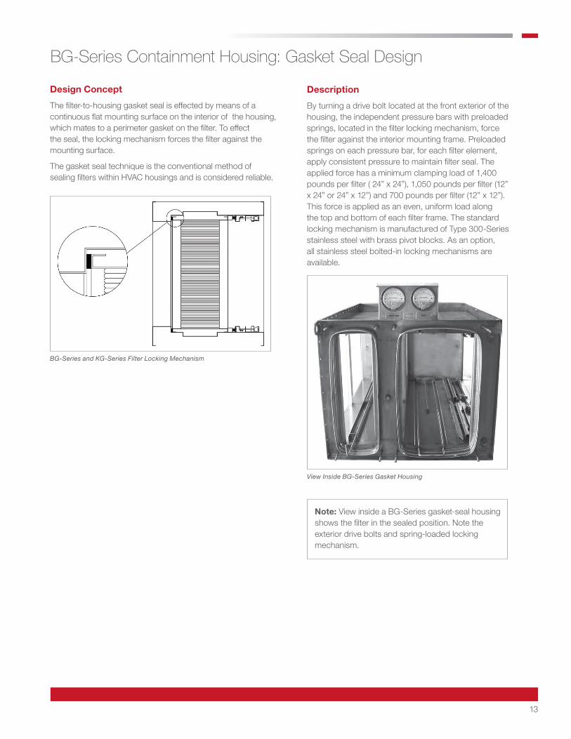
Design Concept
The filter-to-housing gasket seal is effected by means of a continuous flat mounting surface on the interior of the housing, which mates to a perimeter gasket on the filter. To effect the seal, the locking mechanism forces the filter against the mounting surface.
The gasket seal technique is the conventional method of sealing filters within HVAC housings and is considered reliable.
Description
By turning a drive bolt located at the front exterior of the housing, the independent pressure bars with preloaded springs, located in the filter locking mechanism, force the filter against the interior mounting frame. Preloaded springs on each pressure bar, for each filter element, apply consistent pressure to maintain filter seal. The applied force has a minimum clamping load of 1,400 pounds per filter ( 24” x 24”), 1,050 pounds per filter (12” x 24” or 24” x 12”) and 700 pounds per filter (12” x 12”). This force is applied as an even, uniform load along the top and bottom of each filter frame. The standard locking mechanism is manufactured of Type 300-Series stainless steel with brass pivot blocks. As an option, all stainless steel bolted-in locking mechanisms are available.
BG-Series Containment Housing: Gasket Seal Design
BG-Series and KG-Series Filter Locking Mechanism
View Inside BG-Series Gasket Housing
Note: View inside a BG-Series gasket-seal housing shows the filter in the sealed position. Note the exterior drive bolts and spring-loaded locking mechanism.
14
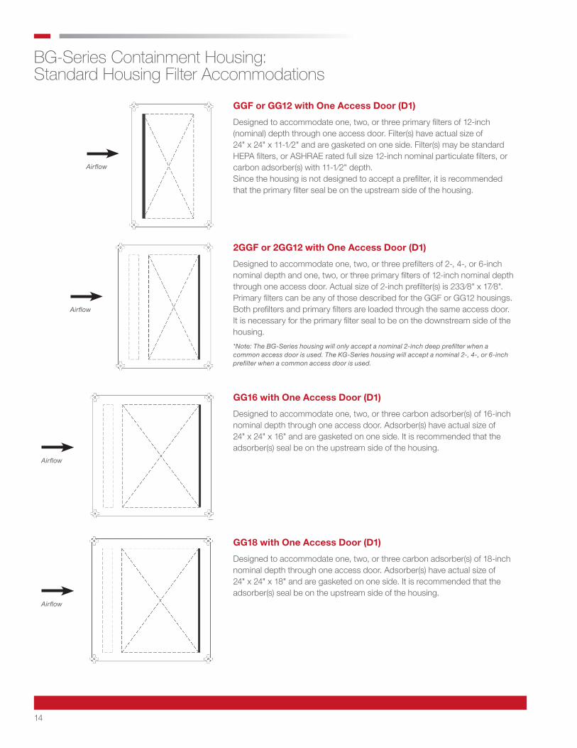
BG-Series Containment Housing: Standard Housing Filter Accommodations
GGF or GG12 with One Access Door (D1)
Designed to accommodate one, two, or three primary filters of 12-inch (nominal) depth through one access door. Filter(s) have actual size of 24" x 24" x 11-1⁄2" and are gasketed on one side. Filter(s) may be standard HEPA filters, or ASHRAE rated full size 12-inch nominal particulate filters, or carbon adsorber(s) with 11-1⁄2" depth. Since the housing is not designed to accept a prefilter, it is recommended that the primary filter seal be on the upstream side of the housing.
2GGF or 2GG12 with One Access Door (D1)
Designed to accommodate one, two, or three prefilters of 2-, 4-, or 6-inch nominal depth and one, two, or three primary filters of 12-inch nominal depth through one access door. Actual size of 2-inch prefilter(s) is 233⁄8" x 17⁄8". Primary filters can be any of those described for the GGF or GG12 housings. Both prefilters and primary filters are loaded through the same access door. It is necessary for the primary filter seal to be on the downstream side of the housing.*Note: The BG-Series housing will only accept a nominal 2-inch deep prefilter when a common access door is used. The KG-Series housing will accept a nominal 2-, 4-, or 6-inch prefilter when a common access door is used.
GG16 with One Access Door (D1)
Designed to accommodate one, two, or three carbon adsorber(s) of 16-inch nominal depth through one access door. Adsorber(s) have actual size of 24" x 24" x 16" and are gasketed on one side. It is recommended that the adsorber(s) seal be on the upstream side of the housing.
GG18 with One Access Door (D1)
Designed to accommodate one, two, or three carbon adsorber(s) of 18-inch nominal depth through one access door. Adsorber(s) have actual size of 24" x 24" x 18" and are gasketed on one side. It is recommended that the adsorber(s) seal be on the upstream side of the housing.
Airflow
Airflow
Airflow
Airflow

15
BG-Series Containment Housing: Standard Housing Filter Accommodations (continued)
2GG16 with Same Access Door (D1)
Designed to accommodate one, two, or three prefilter(s) of 2-inch nominal depth and one, two, or three carbon adsorber(s) of 16-inch nominal depth through one access door. Actual size of 2-inch prefilter(s) is 2-3/8" x 1-7/8". Adsorber(s) have actual size of 24" x 24" x 16" and are gasketed on one side. Both prefilter(s) and adsorber(s) are loaded through the same access door. A popular application of this housing is to position the housing, so the prefilter is downstream of the adsorber, allowing the prefilter to collect carbon dust or “fines” that may come off the adsorber.
2GGF or 2GG12 with Separate Access Doors (D3)
Designed to accommodate the same filters as the previously discussed 2GGF or 2GG12 with the same access door (as shown on page 14), except with this design the prefilters have a separate access door. The principal design advantage of housings with separate access doors for prefilters is to allow the primary filter to seal on the upstream side of the housing. When specifying a housing with separate access doors, give close attention to the access door arrangement code number in the housing’s model number.*Note: Standard 2GG18 housings with same or separate access doors are available. The 2GG18 with the same access door (D1) and the 2GG18 with separate access doors (D3) are the same as the 2GG16 arrangements shown on this page, except the adsorber(s) will have nominal 18-inch depth.
2GG16 with Separate Access Doors (D3)
Same housing design as the 2GG12 with separate access doors, except this housing accommodates nominal 16-inch deep carbon adsorber(s).
Airflow
Airflow
Airflow
16
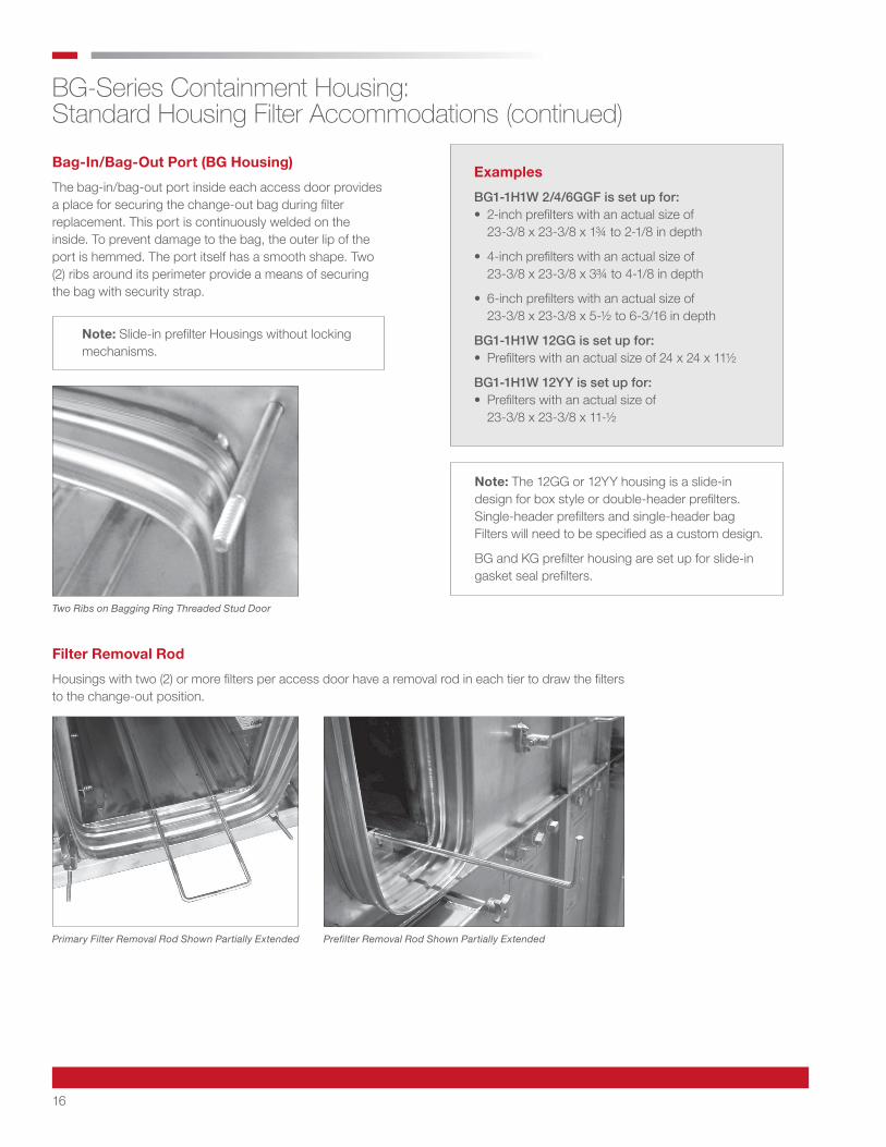
Two Ribs on Bagging Ring Threaded Stud Door
Primary Filter Removal Rod Shown Partially Extended Prefilter Removal Rod Shown Partially Extended
Note: Slide-in prefilter Housings without locking mechanisms.
BG-Series Containment Housing: Standard Housing Filter Accommodations (continued)
Bag-In/Bag-Out Port (BG Housing)
The bag-in/bag-out port inside each access door provides a place for securing the change-out bag during filter replacement. This port is continuously welded on the inside. To prevent damage to the bag, the outer lip of the port is hemmed. The port itself has a smooth shape. Two (2) ribs around its perimeter provide a means of securing the bag with security strap.
Filter Removal Rod
Housings with two (2) or more filters per access door have a removal rod in each tier to draw the filters to the change-out position.
Note: The 12GG or 12YY housing is a slide-in design for box style or double-header prefilters. Single-header prefilters and single-header bag Filters will need to be specified as a custom design.
BG and KG prefilter housing are set up for slide-in gasket seal prefilters.
Examples
BG1-1H1W 2/4/6GGF is set up for: • 2-inch prefilters with an actual size of 23-3/8 x 23-3/8 x 1¾ to 2-1/8 in depth
• 4-inch prefilters with an actual size of 23-3/8 x 23-3/8 x 3¾ to 4-1/8 in depth
• 6-inch prefilters with an actual size of 23-3/8 x 23-3/8 x 5-½ to 6-3/16 in depth
BG1-1H1W 12GG is set up for: • Prefilters with an actual size of 24 x 24 x 11½
BG1-1H1W 12YY is set up for: • Prefilters with an actual size of 23-3/8 x 23-3/8 x 11-½
17
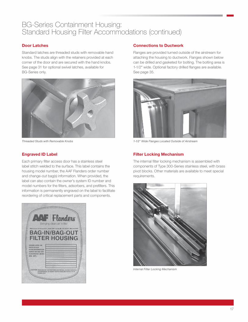
Threaded Studs with Removable Knobs 1-1⁄2" Wide Flanges Located Outside of Airstream
Internal Filter Locking Mechanism
BG-Series Containment Housing: Standard Housing Filter Accommodations (continued)
Door Latches
Standard latches are threaded studs with removable hand knobs. The studs align with the retainers provided at each corner of the door and are secured with the hand knobs. See page 31 for optional swivel latches, available for BG-Series only.
Connections to Ductwork
Flanges are provided turned outside of the airstream for attaching the housing to ductwork. Flanges shown below can be drilled and gasketed for bolting. The bolting area is 1-1/2" wide. Optional factory drilled flanges are available. See page 35.
Engraved ID Label
Each primary filter access door has a stainless steel label stitch welded to the surface. This label contains the housing model number, the AAF Flanders order number and change-out bag(s) information. When provided, the label can also contain the owner’s system ID number and model numbers for the filters, adsorbers, and prefilters. This information is permanently engraved on the label to facilitate reordering of critical replacement parts and components.
Filter Locking Mechanism
The internal filter locking mechanism is assembled with components of Type 300-Series stainless steel, with brass pivot blocks. Other materials are available to meet special requirements.
18
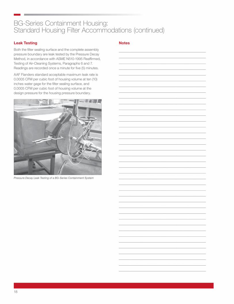
Pressure Decay Leak Testing of a BG-Series Containment System
BG-Series Containment Housing: Standard Housing Filter Accommodations (continued)
Leak Testing
Both the filter sealing surface and the complete assembly pressure boundary are leak tested by the Pressure Decay Method, in accordance with ASME N510-1995 Reaffirmed, Testing of Air-Cleaning Systems, Paragraphs 6 and 7. Readings are recorded once a minute for five (5) minutes.
AAF Flanders standard acceptable maximum leak rate is 0.0005 CFM per cubic foot of housing volume at ten (10) inches water gage for the filter sealing surface, and 0.0005 CFM per cubic foot of housing volume at the design pressure for the housing pressure boundary.
Notes
___________________________________________________ ___________________________________________________ ___________________________________________________ ___________________________________________________ ___________________________________________________ ___________________________________________________ ___________________________________________________ ___________________________________________________ ___________________________________________________ ___________________________________________________ ___________________________________________________ ___________________________________________________ ___________________________________________________ ___________________________________________________ ___________________________________________________ ___________________________________________________ ___________________________________________________ ___________________________________________________ ___________________________________________________ ___________________________________________________ ___________________________________________________ ___________________________________________________ ___________________________________________________ ___________________________________________________ ___________________________________________________ ___________________________________________________ ___________________________________________________ ___________________________________________________ ___________________________________________________ ___________________________________________________ ___________________________________________________ ___________________________________________________ ___________________________________________________ ___________________________________________________ ___________________________________________________ ___________________________________________________ ___________________________________________________ ___________________________________________________ ___________________________________________________
19
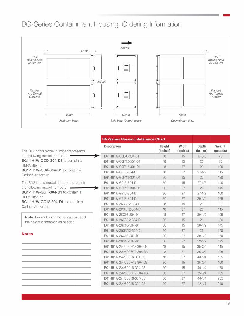
BG-Series Housing Reference Chart
Description Height (inches)
Width (Inches)
Depth (inches)
Weight (pounds)
BG1-1H1W-CCD/6-304-D1 18 15 17-3⁄8 75
BG1-1H1W-CCF/12-304-D1 18 15 23 85
BG1-1H1W-CGF/12-304-D1 18 27 23 100
BG1-1H1W-CG16-304-D1 18 27 27-1⁄2 115
BG1-1H1W-GCF/12-304-D1 30 15 23 120
BG1-1H1W-GC16-304-D1 30 15 27-1⁄2 140
BG1-1H1W-GGF/12-304-D1 30 27 23 145
BG1-1H1W-GG16-304-D1 30 27 27-1⁄2 160
BG1-1H1W-GG18-304-D1 30 27 29-1⁄2 165
BG1-1H1W-2CCF/12-304-D1 18 15 26 90
BG1-1H1W-2CGF/12-304-D1 18 27 26 115
BG1-1H1W-2CG16-304-D1 18 27 30-1⁄2 125
BG1-1H1W-2GCF/12-304-D1 30 15 26 130
BG1-1H1W-2GC16-304-D1 30 15 30-1⁄2 145
BG1-1H1W-2GGF/12-304-D1 30 27 26 155
BG1-1H1W-2GG16-304-D1 30 27 30-1⁄2 170
BG1-1H1W-2GG18-304-D1 30 27 32-1⁄2 175
BG1-1H1W-2/4/6CCF/12-304-D3 18 15 35-3⁄4 115
BG1-1H1W-2/4/6CGF/12-304-D3 18 27 35-3⁄4 145
BG1-1H1W-2/4/6CG16-304-D3 18 27 40-1⁄4 155
BG1-1H1W-2/4/6GCF/12-304-D3 30 15 35-3⁄4 160
BG1-1H1W-2/4/6GC16-304-D3 30 15 40-1⁄4 170
BG1-1H1W-2/4/6GGF/12-304-D3 30 27 35-3⁄4 185
BG1-1H1W-2/4/6GG16-304-D3 30 27 40-1⁄4 205
BG1-1H1W-2/4/6GG18-304-D3 30 27 42-1⁄4 210
BG-Series Containment Housing: Ordering Information
The D/6 in this model number represents the following model numbers:BG1-1H1W-CCD-304-D1 to contain a HEPA filter, or BG1-1H1W-CC6-304-D1 to contain a Carbon Adsorber.
The F/12 in this model number represents the following model numbers:BG1-1H1W-GGF-304-D1 to contain a HEPA filter, or BG1-1H1W-GG12-304-D1 to contain a Carbon Adsorber.
Airflow
1-1/2" Bolting Area All Around
1-1/2" Bolting Area All Around
Flanges Are Turned Outward
Flanges Are Turned Outward
Width Depth Width
Height
4-1/4"
Upstream View Side View (Door Access) Downstream View
Note: For multi-high housings, just add the height dimension as needed.
Notes
_______________________________________ _______________________________________ _______________________________________ _______________________________________ _______________________________________ _______________________________________ _______________________________________ _______________________________________

20
BG-Series Containment Housing: Ordering Information (continued)
Filter Size Designator
HEPA filters and carbon adsorbers — actual filter dimensions are listed:
HEPA Filters *CCD 12 x 12 x 5-7⁄8 *CCF 12 x 12 x 11-1⁄2 *CGF 12 x 24 x 11-1⁄2 *GCF 24 x 12 x 11-1⁄2 *GGF 24 x 24 x 11-1⁄2
Carbon Adsorbers *CC6 12 x 12 x 5-7⁄8 *CC12 12 x 12 x 11-1⁄2 *CG12 12 x 24 x 11-1⁄2 *GC12 24 x 12 x 11-1⁄2 *GG12 24 x 24 x 11-1⁄2 *CG16 12 x 24 x 16 *GC16 24 x 12 x 16 *GG16 24 x 24 x 16 *GG18 24 x 24 x 18
*Insert 2, 4, or 6 to indicate 2-inch, 4-inch, or 6-inch prefilter track.
Housing Series BG1 = Bag-Out Type for Gasket Seal Filters
Nominal Depth of Prefilter 2 = 2-inch Deep Prefilter4 = 4-inch Deep Prefilter6 = 6-inch Deep PrefilterBlank = No Prefilter
Housing Construction Material 304 = Type 304 SST (Standard)304L = Type 304L SST316L = Type 316L SST
Number of Filters High 1H = One Filter High2H = Two Filters High3H = Three Filters High4H = Four Filters High
Number of Filters Wide 1W = One Filter Wide2W = Two Filters Wide3W = Three Filters Wide
Access Door Arrangement D1 = One Access DoorD2 = Two Access Doors, One per SideD3 = Two Access Doors on One Side (One for Primary Filter, One for Prefilter)D4 = Four Access Doors, Two on Each Side (One for Primary Filter, One for Prefilter)
Size Designator of Primary Filter (See Below)
BG1 - 1H2W - 2GGF - 304 - D1
BG-Series Housing Reference Chart
DescriptionHeight (inches)
Width (Inches)
Depth (inches)
Weight (pounds)
BG1-1H1W-2/4/6CC-304-D1 18 15 14 60
BG1-1H1W-2/4/6CG-304-D1 18 27 14 70
BG1-1H1W-2/4/6GC-304-D1 18 15 14 80
BG1-1H1W-2/4/6GG-304-D1 30 27 14 90
BG1-1H2W-GGF/12-304-D1 30 51 23 205
BG1-1H2W-GG16-304-D1 30 51 27-1⁄2 225
BG1-1H2W-GG18-304-D1 30 51 29-1⁄2 235
BG1-1H2W-2GGF/12-304-D1 30 51 26 220
BG1-1H2W-2GG16-304-D1 30 51 20-1⁄2 240
BG1-1H2W-2GG18-304-D1 30 51 32-1⁄2 250
BG1-1H2W-2/4/6GGF/12-304-D3 30 51 35-3⁄4 275
BG1-1H2W-2/4/6GG16-304-D3 30 51 40-1⁄4 295
BG1-1H2W-2/4/6GG18-304-D3 30 51 42-1⁄4 300
BG1-1H2W-2/4/6GG-304-D1 30 51 14 120
BG1-1H3W-GGF/12-304-D1 30 75 23 265
BG1-1H3W-GG16-304-D1 30 75 27-1⁄2 290
BG1-1H3W-GG18-304-D1 30 75 29-1⁄2 300
BG1-1H3W-2GGF/12-304-D1 30 75 26 280
BG1-1H3W-2GG16-304-D1 30 75 30-1⁄2 305
BG1-1H3W-2GG18-304-D1 30 75 32-1⁄2 320
BG1-1H3W-2/4/6GGF/12-304-D3 30 75 35-3⁄4 350
BG1-1H3W-2/4/6GG16-304-D3 30 75 40-1⁄4 375
BG1-1H3W-2/4/6GG18-304-D3 30 75 42-1⁄4 390
BG1-1H3W-2/4/6GG-304-D1 30 75 14 150
❶ These housings are designed to accommodate prefilters only
❶
❶ ❶ ❶ ❶
❶
21
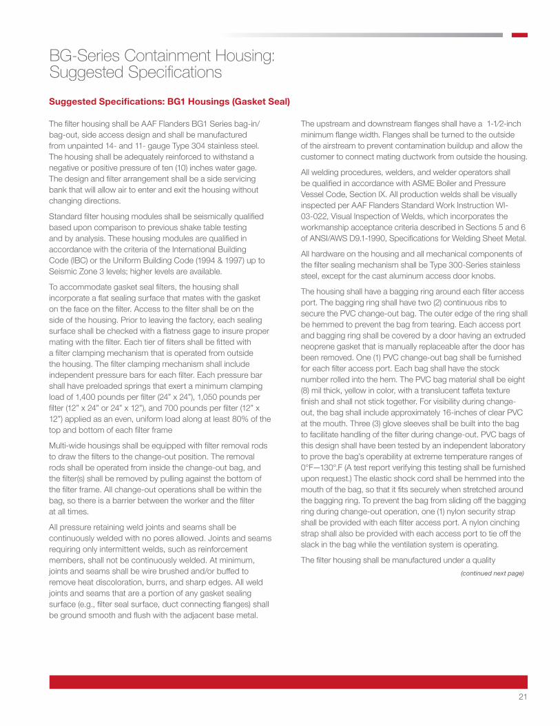
Suggested Specifications: BG1 Housings (Gasket Seal)
The filter housing shall be AAF Flanders BG1 Series bag-in/bag-out, side access design and shall be manufactured from unpainted 14- and 11- gauge Type 304 stainless steel. The housing shall be adequately reinforced to withstand a negative or positive pressure of ten (10) inches water gage. The design and filter arrangement shall be a side servicing bank that will allow air to enter and exit the housing without changing directions.
Standard filter housing modules shall be seismically qualified based upon comparison to previous shake table testing and by analysis. These housing modules are qualified in accordance with the criteria of the International Building Code (IBC) or the Uniform Building Code (1994 & 1997) up to Seismic Zone 3 levels; higher levels are available.
To accommodate gasket seal filters, the housing shall incorporate a flat sealing surface that mates with the gasket on the face on the filter. Access to the filter shall be on the side of the housing. Prior to leaving the factory, each sealing surface shall be checked with a flatness gage to insure proper mating with the filter. Each tier of filters shall be fitted with a filter clamping mechanism that is operated from outside the housing. The filter clamping mechanism shall include independent pressure bars for each filter. Each pressure bar shall have preloaded springs that exert a minimum clamping load of 1,400 pounds per filter (24” x 24”), 1,050 pounds per filter (12” x 24” or 24” x 12”), and 700 pounds per filter (12” x 12”) applied as an even, uniform load along at least 80% of the top and bottom of each filter frame
Multi-wide housings shall be equipped with filter removal rods to draw the filters to the change-out position. The removal rods shall be operated from inside the change-out bag, and the filter(s) shall be removed by pulling against the bottom of the filter frame. All change-out operations shall be within the bag, so there is a barrier between the worker and the filter at all times.
All pressure retaining weld joints and seams shall be continuously welded with no pores allowed. Joints and seams requiring only intermittent welds, such as reinforcement members, shall not be continuously welded. At minimum, joints and seams shall be wire brushed and/or buffed to remove heat discoloration, burrs, and sharp edges. All weld joints and seams that are a portion of any gasket sealing surface (e.g., filter seal surface, duct connecting flanges) shall be ground smooth and flush with the adjacent base metal.
The upstream and downstream flanges shall have a 1-1⁄2-inch minimum flange width. Flanges shall be turned to the outside of the airstream to prevent contamination buildup and allow the customer to connect mating ductwork from outside the housing.
All welding procedures, welders, and welder operators shall be qualified in accordance with ASME Boiler and Pressure Vessel Code, Section IX. All production welds shall be visually inspected per AAF Flanders Standard Work Instruction WI-03-022, Visual Inspection of Welds, which incorporates the workmanship acceptance criteria described in Sections 5 and 6 of ANSI/AWS D9.1-1990, Specifications for Welding Sheet Metal.
All hardware on the housing and all mechanical components of the filter sealing mechanism shall be Type 300-Series stainless steel, except for the cast aluminum access door knobs.
The housing shall have a bagging ring around each filter access port. The bagging ring shall have two (2) continuous ribs to secure the PVC change-out bag. The outer edge of the ring shall be hemmed to prevent the bag from tearing. Each access port and bagging ring shall be covered by a door having an extruded neoprene gasket that is manually replaceable after the door has been removed. One (1) PVC change-out bag shall be furnished for each filter access port. Each bag shall have the stock number rolled into the hem. The PVC bag material shall be eight (8) mil thick, yellow in color, with a translucent taffeta texture finish and shall not stick together. For visibility during change-out, the bag shall include approximately 16-inches of clear PVC at the mouth. Three (3) glove sleeves shall be built into the bag to facilitate handling of the filter during change-out. PVC bags of this design shall have been tested by an independent laboratory to prove the bag’s operability at extreme temperature ranges of 0°F—130°.F (A test report verifying this testing shall be furnished upon request.) The elastic shock cord shall be hemmed into the mouth of the bag, so that it fits securely when stretched around the bagging ring. To prevent the bag from sliding off the bagging ring during change-out operation, one (1) nylon security strap shall be provided with each filter access port. A nylon cinching strap shall also be provided with each access port to tie off the slack in the bag while the ventilation system is operating.
The filter housing shall be manufactured under a quality
BG-Series Containment Housing: Suggested Specifications
(continued next page)

22
assurance program that meets the basic requirements of ASME NQA-1, Quality Assurance Program Requirements for Nuclear Facilities. The manufacturer shall submit documented evidence they have been independently audited by customers at least three (3) times within the last six (6) years to ASME NQA-1 requirements, and successfully passed all three (3) audits. The housing shall be tested for filter fit, operation of the filter clamping mechanism, knife edge alignment, and leak tightness before leaving the factory. The final containment filtration system shall be completely fabricated, assembled, tested, and cleaned at the manufacturer's facility. Subassemblies from outside sources will not be acceptable. Both the filter sealing surface and the complete assembly pressure boundary shall be leak tested by the Pressure Decay Method, in accordance with ASME N510-1995 Reaffirmed, Testing of Air Cleaning Systems, Paragraphs 6 and 7. Pressure readings are recorded once a minute for five (5) minutes. There shall be a maximum leak rate of 0.0005 CFM per cubic foot of housing volume at ten (10) inches water gage.
A minimum of four (4) feet clearance in front of the filter access door is suggested for filter changeout.
BG-Series Containment Housing: Suggested Specifications (continued)
Notes
___________________________________________________ ___________________________________________________ ___________________________________________________ ___________________________________________________ ___________________________________________________ ___________________________________________________ ___________________________________________________ ___________________________________________________ ___________________________________________________ ___________________________________________________ ___________________________________________________ ___________________________________________________ ___________________________________________________ ___________________________________________________ ___________________________________________________ ___________________________________________________ ___________________________________________________ ___________________________________________________ ___________________________________________________ ___________________________________________________ ___________________________________________________ ___________________________________________________ ___________________________________________________ ___________________________________________________ ___________________________________________________ ___________________________________________________ ___________________________________________________ ___________________________________________________ ___________________________________________________ ___________________________________________________ ___________________________________________________ ___________________________________________________ ___________________________________________________ ___________________________________________________ ___________________________________________________ ___________________________________________________ ___________________________________________________ ___________________________________________________ ___________________________________________________
Note: Throughout the product bulletin we make reference to standards that are old and or revised. Our purpose in specifying the older versions of standards is due to the nature of these products and where they are typically used.
During the years and numerous revisions, these standards have become less stringent than their original versions. We believe in manufacturing and referencing the critical versions to help the owners maintain the stringent requirements this industry originally intended.
23
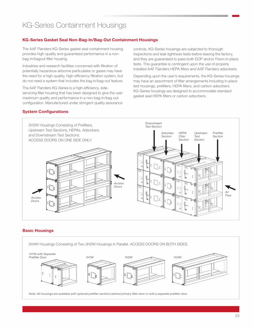
The AAF Flanders KG-Series gasket seal containment housing provides high-quality and guaranteed performance in a non-bag-in/bagout filter housing.
Industries and research facilities concerned with filtration of potentially hazardous airborne particulates or gases may have the need for a high-quality, high-efficiency filtration system, but do not need a system that includes the bag in/bag-out feature.
The AAF Flanders KG-Series is a high-efficiency, side-servicing filter housing that has been designed to give the user maximum quality and performance in a non-bag-in/bag-out configuration. Manufactured under stringent quality assurance
KG-Series Gasket Seal Non-Bag-In/Bag-Out Containment Housings
System Configurations
Basic Housings
KG-Series Containment Housings
controls, KG-Series housings are subjected to thorough inspections and leak tightness tests before leaving the factory, and they are guaranteed to pass both DOP and/or Freon in-place tests. This guarantee is contingent upon the use of properly installed AAF Flanders HEPA filters and AAF Flanders adsorbers.
Depending upon the user’s requirements, the KG-Series housings may have an assortment of filter arrangements including in-place test housings, prefilters, HEPA filters, and carbon adsorbers. KG-Series housings are designed to accommodate standard gasket seal HEPA filters or carbon adsorbers.
Access Doors
DownstreamTest Section
1H1W with SeparatePrefilter Door
Note: All housings are available with optional prefilter sections behind primary filter door or with a separate prefilter door.
1H1W 1H2W 1H3W
AdsorberSection
HEPAFilterSection
UpstreamTestSection
PrefilterSection
Access Doors
Air Flow
3H2W Housings Consisting of Prefilters, Upstream Test Sections, HEPAs, Adsorbers and Downstream Test Sections. ACCESS DOORS ON ONE SIDE ONLY.
3H4W Housings Consisting of Two 3H2W Housings in Parallel. ACCESS DOORS ON BOTH SIDES.
24
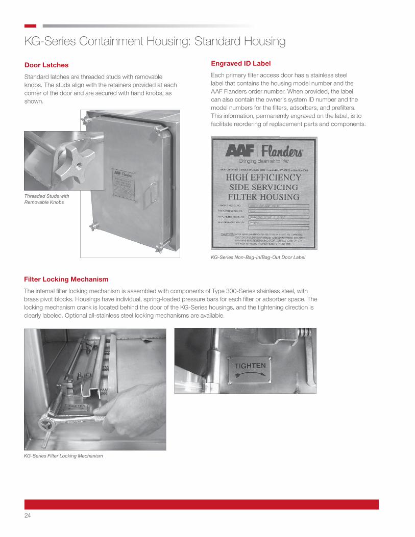
Threaded Studs with Removable Knobs
KG-Series Non-Bag-In/Bag-Out Door Label
KG-Series Filter Locking Mechanism
KG-Series Containment Housing: Standard Housing
Door Latches
Standard latches are threaded studs with removable knobs. The studs align with the retainers provided at each corner of the door and are secured with hand knobs, as shown.
Engraved ID Label
Each primary filter access door has a stainless steel label that contains the housing model number and the AAF Flanders order number. When provided, the label can also contain the owner’s system ID number and the model numbers for the filters, adsorbers, and prefilters. This information, permanently engraved on the label, is to facilitate reordering of replacement parts and components.
Filter Locking Mechanism
The internal filter locking mechanism is assembled with components of Type 300-Series stainless steel, with brass pivot blocks. Housings have individual, spring-loaded pressure bars for each filter or adsorber space. The locking mechanism crank is located behind the door of the KG-Series housings, and the tightening direction is clearly labeled. Optional all-stainless steel locking mechanisms are available.
25
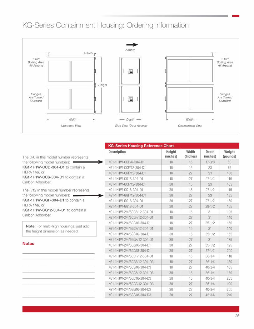
KG-Series Housing Reference Chart
Description Height (inches)
Width (Inches)
Depth (inches)
Weight (pounds)
KG1-1H1W-CCD/6-304-D1 18 15 17-3⁄8 60
KG1-1H1W-CCF/12-304-D1 18 15 23 75
KG1-1H1W-CGF/12-304-D1 18 27 23 100
KG1-1H1W-CG16-304-D1 18 27 27-1⁄2 110
KG1-1H1W-GCF/12-304-D1 30 15 23 105
KG1-1H1W-GC16-304-D1 30 15 27-1⁄2 115
KG1-1H1W-GGF/12-304-D1 30 27 23 135
KG1-1H1W-GG16-304-D1 30 27 27-1⁄2 150
KG1-1H1W-GG18-304-D1 30 27 29-1⁄2 155
KG1-1H1W-2/4/6CCF/12-304-D1 18 15 31 105
KG1-1H1W-2/4/6CGF/12-304-D1 18 27 31 140
KG1-1H1W-2/4/6CG16-304-D1 18 27 35-1⁄2 150
KG1-1H1W-2/4/6GCF/12-304-D1 30 15 31 140
KG1-1H1W-2/4/6GC16-304-D1 30 15 35-1⁄2 155
KG1-1H1W-2/4/6GGF/12-304-D1 30 27 31 175
KG1-1H1W-2/4/6GG16-304-D1 30 27 35-1⁄2 195
KG1-1H1W-2/4/6GG18-304-D1 30 27 37-1⁄2 200
KG1-1H1W-2/4/6CCF/12-304-D1 18 15 36-1⁄4 110
KG1-1H1W-2/4/6CGF/12-304-D3 18 27 36-1⁄4 150
KG1-1H1W-2/4/6CG16-304-D3 18 27 40-3⁄4 165
KG1-1H1W-2/4/6GCF/12-304-D3 30 15 36-1⁄4 150
KG1-1H1W-2/4/6GC16-304-D3 30 15 40-3⁄4 265
KG1-1H1W-2/4/6GGF/12-304-D3 30 27 36-1⁄4 190
KG1-1H1W-2/4/6GG16-304-D3 30 27 40-3⁄4 205
KG1-1H1W-2/4/6GG18-304-D3 30 27 42-3⁄4 210
KG-Series Containment Housing: Ordering Information
The D/6 in this model number represents the following model numbers:KG1-1H1W-CCD-304-D1 to contain a HEPA filter, or KG1-1H1W-CC6-304-D1 to contain a Carbon Adsorber.
The F/12 in this model number represents the following model numbers:KG1-1H1W-GGF-304-D1 to contain a HEPA filter, or KG1-1H1W-GG12-304-D1 to contain a Carbon Adsorber.
1-1/2" Bolting Area All Around
Flanges Are Turned Outward
Note: For multi-high housings, just add the height dimension as needed.
Notes
_______________________________________ _______________________________________ _______________________________________ _______________________________________ _______________________________________ _______________________________________ _______________________________________ _______________________________________
Airflow
1-1/2" Bolting Area All Around
1-1/2" Bolting Area All Around
Flanges Are Turned Outward
Flanges Are Turned Outward
Width Depth Width
Height
2-3/4"
Upstream View Side View (Door Access) Downstream View
26
KG-Series Housing Reference Chart
DescriptionHeight (inches)
Width (Inches)
Depth (inches)
Weight (pounds)
KG1-1H1W-2/4/6CC-304-D1 18 15 14 50
KG1-1H1W-2/4/6CG-304-D1 18 27 14 60
KG1-1H1W-2/4/6GC-304-D1 30 15 14 70
KG1-1H1W-2/4/6GG-304-D1 30 27 14 80
KG1-1H2W-GGF/12-304-D1 30 51 23 200
KG1-1H2W-GG16-304-D1 30 51 27-1⁄2 220
KG1-1H2W-GG18-304-D1 30 51 29-1⁄2 225
KG1-1H2W-2/4/6GGF/12-304-D1 30 51 31 255
KG1-1H2W-2/4/6GG16-304-D1 30 51 35-1⁄2 275
KG1-1H2W-2/4/6GG18-304-D1 30 51 37-1⁄2 285
KG1-1H2W-2/4/6GGF/12-304-D3 30 51 36-1⁄4 275
KG1-1H2W-2/4/6GG16-304-D3 30 51 40-3⁄4 295
KG1-1H2W-2/4/6GG18-304-D3 30 51 42-3⁄4 305
KG1-1H2W-2/4/6GG-304-D1 30 51 14 100
KG1-1H3W-GGF/12-304-D1 30 75 23 265
KG1-1H3W-GG16-304-D1 30 75 27-1⁄2 290
KG1-1H3W-GG18-304-D1 30 75 29-1⁄2 300
KG1-1H3W-2/4/6GGF/12-304-D1 30 75 31 325
KG1-1H3W-2/4/6GG16-304-D1 30 75 35-1⁄2 350
KG1-1H3W-2/4/6GG18-304-D1 30 75 37-1⁄2 365
KG1-1H3W-2/4/6GGF/12-304-D3 30 75 36-1⁄2 360
KG1-1H3W-2/4/6GG16-304-D3 30 75 40-3⁄4 385
KG1-1H3W-2/4/6GG18-304-D3 30 75 42-3⁄4 395
KG1-1H3W-2/4/6GG-304-D1 30 75 14 120
❶ These housings are designed to accommodate prefilters only
KG-Series Containment Housing: Ordering Information (continued)
❶
❶
❶ ❶ ❶ ❶
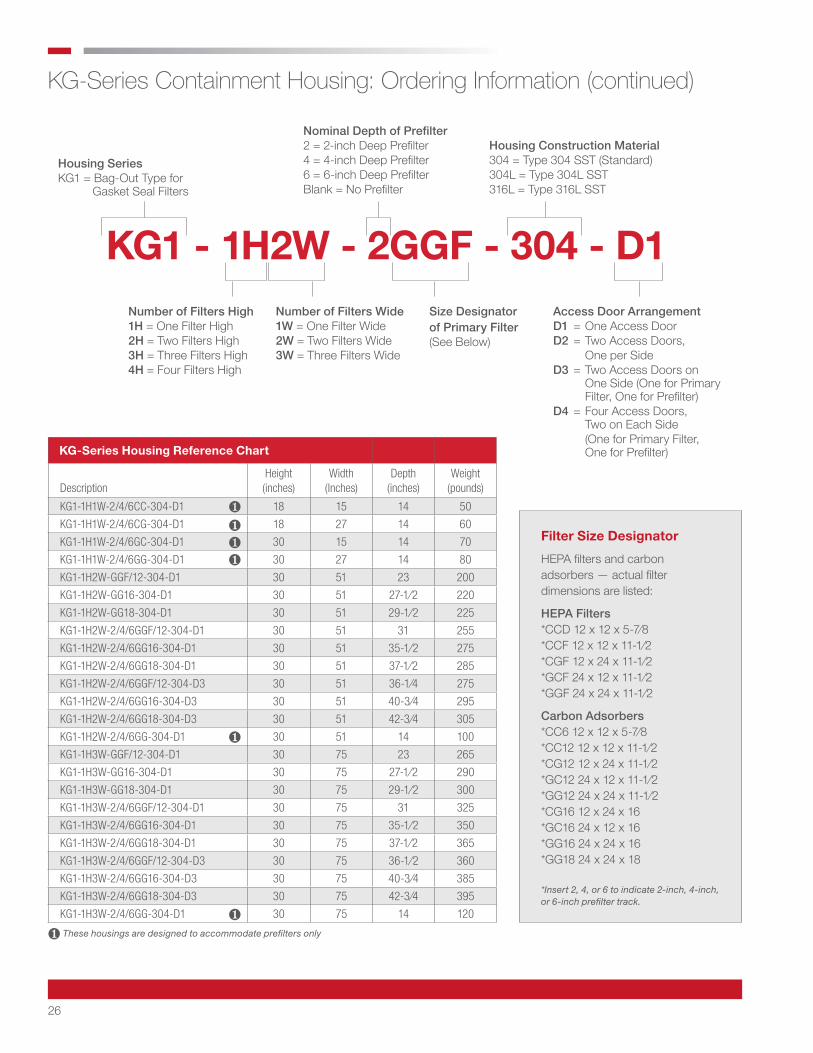
Filter Size Designator
HEPA filters and carbon adsorbers — actual filter dimensions are listed:
HEPA Filters *CCD 12 x 12 x 5-7⁄8 *CCF 12 x 12 x 11-1⁄2 *CGF 12 x 24 x 11-1⁄2 *GCF 24 x 12 x 11-1⁄2 *GGF 24 x 24 x 11-1⁄2
Carbon Adsorbers *CC6 12 x 12 x 5-7⁄8 *CC12 12 x 12 x 11-1⁄2 *CG12 12 x 24 x 11-1⁄2 *GC12 24 x 12 x 11-1⁄2 *GG12 24 x 24 x 11-1⁄2 *CG16 12 x 24 x 16 *GC16 24 x 12 x 16 *GG16 24 x 24 x 16 *GG18 24 x 24 x 18
*Insert 2, 4, or 6 to indicate 2-inch, 4-inch, or 6-inch prefilter track.
Housing Series KG1 = Bag-Out Type for Gasket Seal Filters
Nominal Depth of Prefilter 2 = 2-inch Deep Prefilter4 = 4-inch Deep Prefilter6 = 6-inch Deep PrefilterBlank = No Prefilter
Housing Construction Material 304 = Type 304 SST (Standard)304L = Type 304L SST316L = Type 316L SST
Number of Filters High 1H = One Filter High2H = Two Filters High3H = Three Filters High4H = Four Filters High
Number of Filters Wide 1W = One Filter Wide2W = Two Filters Wide3W = Three Filters Wide
Access Door Arrangement D1 = One Access DoorD2 = Two Access Doors, One per SideD3 = Two Access Doors on One Side (One for Primary Filter, One for Prefilter)D4 = Four Access Doors, Two on Each Side (One for Primary Filter, One for Prefilter)
Size Designator of Primary Filter (See Below)
KG1 - 1H2W - 2GGF - 304 - D1
27
Suggested Specifications: KG1 Housings (Gasket Seal)
The filter housing shall be AAF Flanders KG1 Series non-bag-in/bag-out, side access design and shall be manufactured from unpainted 14- and 11-gauge Type 304 stainless steel. The housing shall be adequately reinforced to withstand a negative or positive pressure of ten (10) inches water gage. The design and filter arrangement shall be a side servicing bank that will allow air to enter and exit the housing without changing directions.
To accommodate gasket seal filters, the housing shall incorporate a flat sealing surface that mates with the gasket on the face on the filter. Access to the filter shall be on the side of the housing. Prior to leaving the factory, each sealing surface shall be checked with a flatness gage to insure proper mating with the filter. Each tier of filters shall be fitted with a filter clamping mechanism that is operated from outside the housing. The filter clamping mechanism shall include independent pressure bars for each filter. Each pressure bar shall have preloaded springs that exert a minimum clamping load of 1,400 pounds per filter ( 24” x 24”), 1,050 pounds per filter (12” x 24” or 24” x 12”), and 700 pounds per filter (12” x 12”) applied as an even, uniform load along at least 80% of the top and bottom of each filter frame.
Multi-wide housings shall be equipped with prefilter removal rods (optional for primary filter) to draw the filters to the change-out position. The removal rod shall be operated from inside of the door, and the prefilter(s) shall be removed by pulling against the bottom of the prefilter frame.
All pressure retaining weld joints and seams shall be continuously welded with no pores allowed. Joints and seams requiring only intermittent welds, such as reinforcement members, shall not be continuously welded. At minimum, joints and seams shall be wire brushed and/or buffed to remove heat discoloration, burrs, and sharp edges. All weld joints and seams that are a portion of any gasket sealing surface (e.g., filter seal surface, duct connecting flanges) shall be ground smooth and flush with the adjacent base metal.
The upstream and downstream flanges shall have a 1-1⁄2-inch minimum flange width. Flanges shall be turned to the outside of the airstream to prevent contamination buildup and allow the customer to connect mating duct work from outside the housing.
All welding procedures, welders, and welder operators shall be qualified in accordance with ASME Boiler and Pressure Vessel Code, Section IX. All production welds shall be visually inspected per AAF Flanders Standard Work Instruction WI-03-022, Visual Inspection of Welds, which incorporates the workmanship acceptance criteria described in Sections 5 and 6 of ANSI/AWS D9.1-1990, Specifications for Welding Sheet Metal.
All hardware on the housing and all mechanical components of the filter sealing mechanism shall be Type 300-Series stainless steel, except for the cast aluminum access door knobs and brass pivot blocks in the filter sealing mechanism (i.e., to prevent galling).
Each access port shall be covered by a door having an extruded neoprene gasket that is manually replaceable after the door has been removed.
The filter housing shall be manufactured under a quality assurance program that meets the basic requirements of ASME NQA-1, Quality Assurance Program Requirements for Nuclear Facilities. The manufacturer shall submit documented evidence they have been independently audited by customers at least three (3) times within the last six (6) years to ASME NQA-1 requirements, and successfully passed all three (3) audits. The housing shall be tested for filter fit, operation of the filter clamping mechanism, knife edge alignment, and leak tightness before leaving the factory. The final containment filtration system shall be completely fabricated, assembled, tested, and cleaned at the manufacturer's facility. Subassemblies from outside sources will not be acceptable. Both the filter sealing surface and the complete assembly pressure boundary shall be leak tested by the Pressure Decay Method, in accordance with ASME N510-1995 Reaffirmed, Testing of Air Cleaning Systems, Paragraphs 6 and 7. Pressure readings are recorded once a minute for five (5) minutes. There shall be a maximum leak rate of 0.0005 CFM per cubic foot of housing volume at ten (10) inches water gage. A minimum of three (3) feet clearance in front of the filter access door is suggested for filter change-out.
KG-Series Containment Housing: Suggested Specifications
Note: Throughout the product bulletin we make reference to standards that are old and or revised. Our purpose in specifying the older versions of standards is due to the nature of these products and where they are typically used.
During the years and numerous revisions, these standards have become less stringent than their original versions. We believe in manufacturing and referencing the critical versions to help the owners maintain the stringent requirements this industry originally intended.
28
KG-Series Containment Housing: Suggested Specifications Notes
Notes
______________________________________________________________________________________________________________ ______________________________________________________________________________________________________________ ______________________________________________________________________________________________________________ ______________________________________________________________________________________________________________ ______________________________________________________________________________________________________________ ______________________________________________________________________________________________________________ ______________________________________________________________________________________________________________ ______________________________________________________________________________________________________________ ______________________________________________________________________________________________________________ ______________________________________________________________________________________________________________ ______________________________________________________________________________________________________________ ______________________________________________________________________________________________________________ ______________________________________________________________________________________________________________ ______________________________________________________________________________________________________________ ______________________________________________________________________________________________________________ ______________________________________________________________________________________________________________ ______________________________________________________________________________________________________________ ______________________________________________________________________________________________________________ ______________________________________________________________________________________________________________ ______________________________________________________________________________________________________________ ______________________________________________________________________________________________________________ ______________________________________________________________________________________________________________ ______________________________________________________________________________________________________________ ______________________________________________________________________________________________________________ ______________________________________________________________________________________________________________ ______________________________________________________________________________________________________________ ______________________________________________________________________________________________________________ ______________________________________________________________________________________________________________ ______________________________________________________________________________________________________________ ______________________________________________________________________________________________________________ ______________________________________________________________________________________________________________ ______________________________________________________________________________________________________________ ______________________________________________________________________________________________________________ ______________________________________________________________________________________________________________ ______________________________________________________________________________________________________________ ______________________________________________________________________________________________________________

29
AstroSafe® BG and KG-Series Containment Housing: Available Options
• Deformation Testing• Spore Sample Ports• Decontamination Ports• Air Blenders• Face and By-Pass Dampers• Humidifiers• Moisture Separators• Portability Casters• All Stainless Steel Locking Mechanisms• 1⁄4-inch Plate Flanges• 150# Class Slip-on Flanges• Plenums• Mounting Bases• High Temperature Design• Fans/Controls• Seismic Design• Hansen Connectors• Electric Heaters• Acid Resistant Materials• Special Polished Finishes• Insulation• Silicone Door Gasket• Ratchet/Socket/Extension• Filter Removal Rod
• Prefilter Sections• Static Pressure Taps• Pressure Gages• 300-Series SST Gauge Fittings and Tubing• DOP/Freon Test Ports• Lifting Lugs• Swivel Door Latches (BG-Series)• Weather Caps• Bead Blast Finish• Transitions• In-Place Test Housings• Scan Test Housings• Metal Door Pocket• Additional PVC Bags• Additional Security Straps• Additional Cinching Straps• Filter Removable Tray• Banding Kit• Moisture Drains and Valves• Drilled Flanges• Certified Weld Inspection (CWI)• Liquid Dye Penetrant Testing• Special Low Leakage Testing• High/Low Pressure Design
BG and KG-Series Available Options
30
AstroSafe® BG and KG-Series Containment Housing: Available Options (continued)
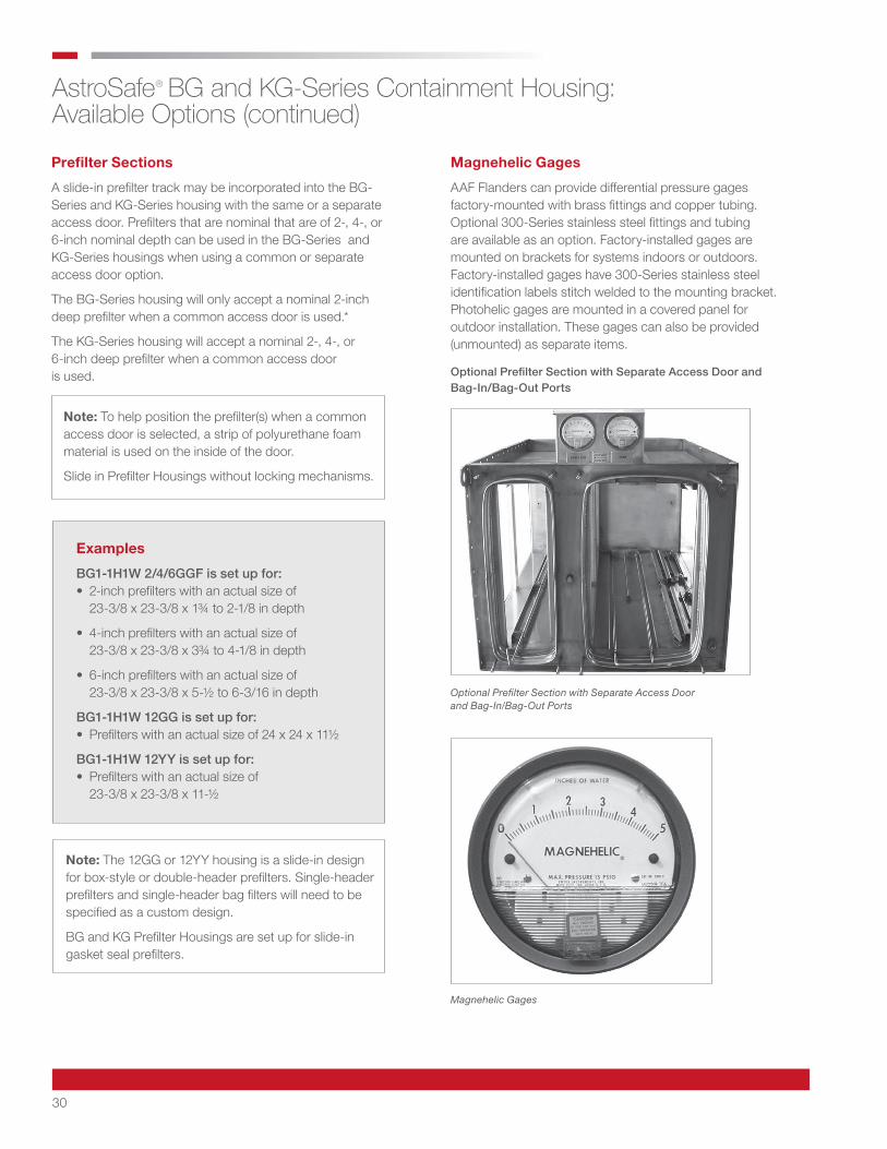
Optional Prefilter Section with Separate Access Door and Bag-In/Bag-Out Ports
Optional Prefilter Section with Separate Access Door and Bag-In/Bag-Out Ports
Note: To help position the prefilter(s) when a common access door is selected, a strip of polyurethane foam material is used on the inside of the door.
Slide in Prefilter Housings without locking mechanisms.
Prefilter Sections
A slide-in prefilter track may be incorporated into the BG-Series and KG-Series housing with the same or a separate access door. Prefilters that are nominal that are of 2-, 4-, or 6-inch nominal depth can be used in the BG-Series and KG-Series housings when using a common or separate access door option.
The BG-Series housing will only accept a nominal 2-inch deep prefilter when a common access door is used.*
The KG-Series housing will accept a nominal 2-, 4-, or 6-inch deep prefilter when a common access door is used.
Note: The 12GG or 12YY housing is a slide-in design for box-style or double-header prefilters. Single-header prefilters and single-header bag filters will need to be specified as a custom design.
BG and KG Prefilter Housings are set up for slide-in gasket seal prefilters.
Examples
BG1-1H1W 2/4/6GGF is set up for: • 2-inch prefilters with an actual size of 23-3/8 x 23-3/8 x 1¾ to 2-1/8 in depth
• 4-inch prefilters with an actual size of 23-3/8 x 23-3/8 x 3¾ to 4-1/8 in depth
• 6-inch prefilters with an actual size of 23-3/8 x 23-3/8 x 5-½ to 6-3/16 in depth
BG1-1H1W 12GG is set up for: • Prefilters with an actual size of 24 x 24 x 11½
BG1-1H1W 12YY is set up for: • Prefilters with an actual size of 23-3/8 x 23-3/8 x 11-½
Magnehelic Gages
Magnehelic Gages
AAF Flanders can provide differential pressure gages factory-mounted with brass fittings and copper tubing. Optional 300-Series stainless steel fittings and tubing are available as an option. Factory-installed gages are mounted on brackets for systems indoors or outdoors. Factory-installed gages have 300-Series stainless steel identification labels stitch welded to the mounting bracket. Photohelic gages are mounted in a covered panel for outdoor installation. These gages can also be provided (unmounted) as separate items.
31
AstroSafe® BG and KG-Series Containment Housing: Available Options (continued)
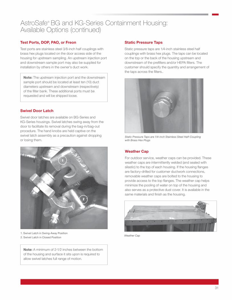
1. Swivel Latch in Swing-Away Position
2. Swivel Latch in Closed Position
Swivel Door Latch
Swivel door latches are available on BG-Series and KG-Series housings. Swivel latches swing away from the door to facilitate its removal during the bag-in/bag-out procedure. The hand knobs are held captive on the swivel latch assembly as a precaution against dropping or losing them.
Note: A minimum of 2-1⁄2 inches between the bottom of the housing and surface it sits upon is required to allow swivel latches full range of motion.
1
2
Test Ports, DOP, PAO, or Freon
Test ports are stainless steel 3⁄8-inch half couplings with brass hex plugs located on the door access side of the housing for upstream sampling. An upstream injection port and downstream sample port may also be supplied for installation by others in the owner’s duct work.
Note: The upstream injection port and the downstream sample port should be located at least ten (10) duct diameters upstream and downstream (respectively) of the filter bank. These additional ports must be requested and will be shipped loose.
Static Pressure Taps are 1/4-inch Stainless Steel Half-Coupling with Brass Hex Plugs
Static Pressure Taps
Static pressure taps are 1⁄4-inch stainless steel half couplings with brass hex plugs. The taps can be located on the top or the back of the housing upstream and downstream of the prefilters and/or HEPA filters. The customer should specify the quantity and arrangement of the taps across the filters..
Weather Cap
Weather Cap
For outdoor service, weather caps can be provided. These weather caps are intermittently welded (and sealed with silastic) to the top of each housing. If the housing flanges are factory-drilled for customer ductwork connections, removable weather caps are bolted to the housing to provide access to the top flanges. The weather cap helps minimize the pooling of water on top of the housing and also serves as a protective dust cover. It is available in the same materials and finish as the housing.
32
AstroSafe® BG and KG-Series Containment Housing: Available Options (continued)
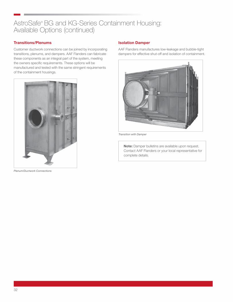
Plenum/Ductwork Connections
Transitions/Plenums
Customer ductwork connections can be joined by incorporating transitions, plenums, and dampers. AAF Flanders can fabricate these components as an integral part of the system, meeting the owners specific requirements. These options will be manufactured and tested with the same stringent requirements of the containment housings.
Transition with Damper
Isolation Damper
AAF Flanders manufactures low-leakage and bubble-tight dampers for effective shut-off and isolation of containment.
Note: Damper bulletins are available upon request. Contact AAF Flanders or your local representative for complete details.

33
AstroSafe® BG and KG-Series Containment Housing: Available Options (continued)
Bead Blast Finish
Housings are constructed using stainless steel with 2B mill finish. They are then bead-blasted after fabrication to achieve a clean, smooth and neutral finish. This process is an environmentally safe glass bead blast system with aesthetic results.
In-Place Test Housings
Where HEPA filters must be tested for efficiency while in service, AAF Flanders provides DOP or Freon test housings that can be incorporated at the factory into the BG-Series and KG-Series system.
These housings solve numerous problems associated with in-service testing. Properly installed test sections eliminate the need for injection ports and sampling ports to be located ten (10) duct diameters away from the filter bank. They allow individual filters to be tested for leakage, which is a more stringent test than testing an entire bank of filters at a time. The tests are conducted from outside the system, thereby avoiding exposure of test personnel to toxic materials.
Note: Test section bulletins are available upon request. Contact AAF Flanders or your local representative for complete details.
Note: Scan test housing bulletins are available upon request. Contact AAF Flanders or your local representative for complete details.
Scan Probe Assembly with Scanning Wand and Ball Valve Shutoff
Scan Test Housings
The integrity of many containment systems is adequately determined by testing the overall efficiency of the filters. Other systems require individual filters to be scan-tested periodically while in service to locate “pinhole" leaks in the filters. If any are present, the filters may be replaced.
This capability is achieved in a BG-Series and KG-Series system by incorporating AAF Flanders scan test housings directly down stream of the filters to be tested.
34
AstroSafe® BG and KG-Series Containment Housing: Available Options (continued)
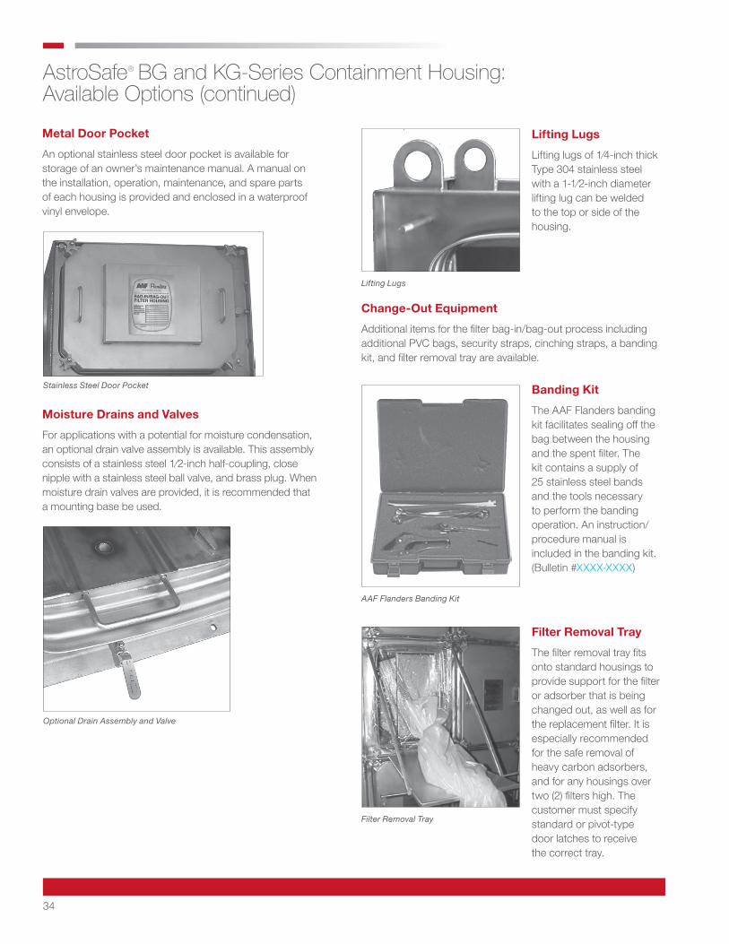
Stainless Steel Door Pocket
Optional Drain Assembly and Valve
Filter Removal Tray
Lifting Lugs
AAF Flanders Banding Kit
Banding Kit
The AAF Flanders banding kit facilitates sealing off the bag between the housing and the spent filter. The kit contains a supply of 25 stainless steel bands and the tools necessary to perform the banding operation. An instruction/procedure manual is included in the banding kit. (Bulletin #XXXX-XXXX)
Lifting Lugs
Lifting lugs of 1⁄4-inch thick Type 304 stainless steel with a 1-1⁄2-inch diameter lifting lug can be welded to the top or side of the housing.
Change-Out Equipment
Additional items for the filter bag-in/bag-out process including additional PVC bags, security straps, cinching straps, a banding kit, and filter removal tray are available.
Metal Door Pocket
An optional stainless steel door pocket is available for storage of an owner’s maintenance manual. A manual on the installation, operation, maintenance, and spare parts of each housing is provided and enclosed in a waterproof vinyl envelope.
Moisture Drains and Valves
For applications with a potential for moisture condensation, an optional drain valve assembly is available. This assembly consists of a stainless steel 1⁄2-inch half-coupling, close nipple with a stainless steel ball valve, and brass plug. When moisture drain valves are provided, it is recommended that a mounting base be used.
Filter Removal Tray
The filter removal tray fits onto standard housings to provide support for the filter or adsorber that is being changed out, as well as for the replacement filter. It is especially recommended for the safe removal of heavy carbon adsorbers, and for any housings over two (2) filters high. The customer must specify standard or pivot-type door latches to receive the correct tray.
35
AstroSafe® BG and KG-Series Containment Housing: Available Options (continued)
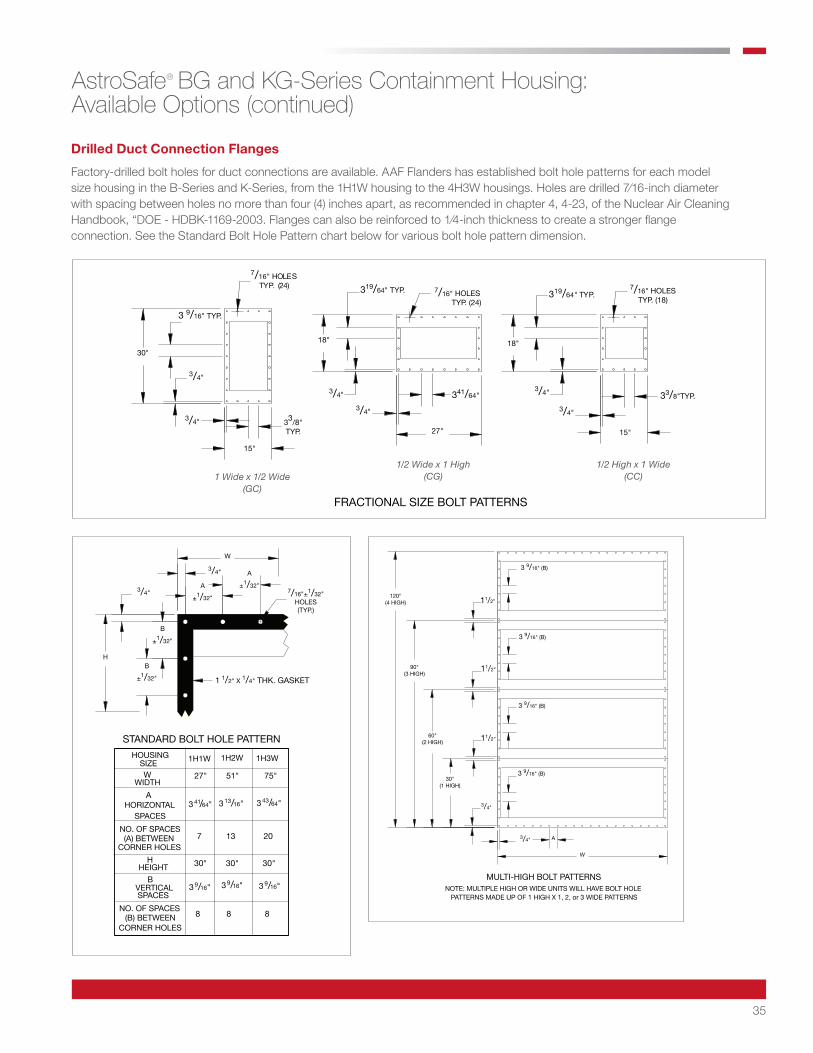
Drilled Duct Connection Flanges
Factory-drilled bolt holes for duct connections are available. AAF Flanders has established bolt hole patterns for each model size housing in the B-Series and K-Series, from the 1H1W housing to the 4H3W housings. Holes are drilled 7⁄16-inch diameter with spacing between holes no more than four (4) inches apart, as recommended in chapter 4, 4-23, of the Nuclear Air Cleaning Handbook, “DOE - HDBK-1169-2003. Flanges can also be reinforced to 1⁄4-inch thickness to create a stronger flange connection. See the Standard Bolt Hole Pattern chart below for various bolt hole pattern dimension.
FRACTIONAL SIZE BOLT PATTERNS
7/16" HOLESTYP. (24)
15"
30"
3 9/16" TYP.
3/4"
18"
27"
HOLESTYP. (24)
7/16" HOLESTYP. (18)
33/8"TYP.
15"
18"
319/64" TYP.
3/4" 33/8"TYP.
319/64" TYP. 7/16"
341/64"3/4"3/4"
3/4"
3/4"
1/2 Wide x 1 High (CG)1 Wide x 1/2 Wide
(GC)
1/2 High x 1 Wide (CC)
NO. OF SPACES
CORNER HOLES(B) BETWEEN
SPACESVERTICAL
B
8 8 8
HEIGHTH
CORNER HOLES
NO. OF SPACES(A) BETWEEN
A
SPACESHORIZONTAL
WWIDTH
SIZEHOUSING
30"
7
30"30"
2013
27" 51" 75"
1H2W1H1W 1H3W
STANDARD BOLT HOLE PATTERN
3 41/64" 3 13/16" 3 43/64"
3 9/16" 3 9/16" 3 9/16"
7/16"±1/32"HOLES(TYP.)
HB
±1/32" 1 1/2" X 1/4" THK. GASKET
B
±1/32"
3/4"
W
3/4" A
±1/32"A
±1/32"
MULTI-HIGH BOLT PATTERNSNOTE: MULTIPLE HIGH OR WIDE UNITS WILL HAVE BOLT HOLE
PATTERNS MADE UP OF 1 HIGH X 1, 2, or 3 WIDE PATTERNS
W
30"(1 HIGH)
60"(2 HIGH)
90"(3 HIGH)
120"(4 HIGH)
A
3 9/16" (B)
3 9/16" (B)
3 9/16" (B)
3 9/16" (B)
3/4"
3/4"
11/2"
11/2"
11/2"
36
AstroSafe® BG and KG-Series Containment Housing: General Design Considerations
Design Considerations
One important consideration to remember in any design layout involving a filter housing is the amount of room required to conduct the filter change-out. AAF Flanders recommends a minimum of four (4)-feet (for BG-Series housings) and three (3)-feet (for KG-Series housings) be allowed between the housing access door and any obstructions.
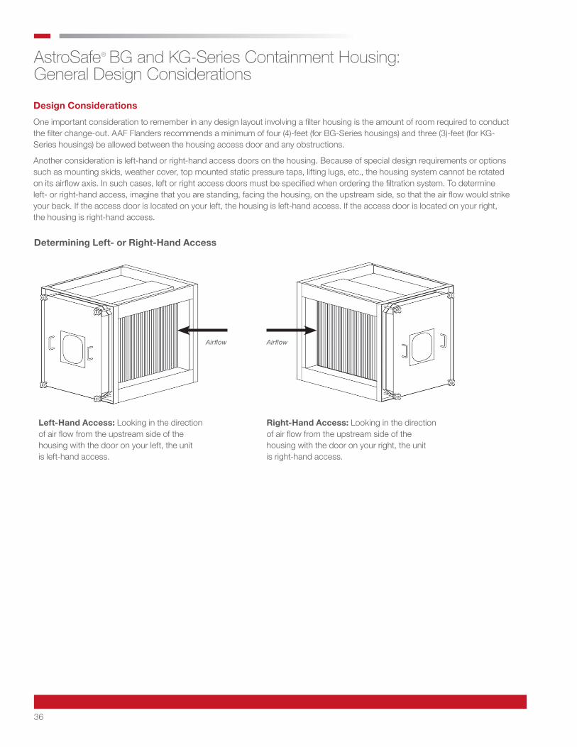
Another consideration is left-hand or right-hand access doors on the housing. Because of special design requirements or options such as mounting skids, weather cover, top mounted static pressure taps, lifting lugs, etc., the housing system cannot be rotated on its airflow axis. In such cases, left or right access doors must be specified when ordering the filtration system. To determine left- or right-hand access, imagine that you are standing, facing the housing, on the upstream side, so that the air flow would strike your back. If the access door is located on your left, the housing is left-hand access. If the access door is located on your right, the housing is right-hand access.
Determining Left- or Right-Hand Access
AirflowAirflow
Left-Hand Access: Looking in the direction of air flow from the upstream side of the housing with the door on your left, the unit is left-hand access.
Right-Hand Access: Looking in the direction of air flow from the upstream side of the housing with the door on your right, the unit is right-hand access.
37
AstroSafe® BG and KG-Series Containment Housing: General Design Considerations (continued)
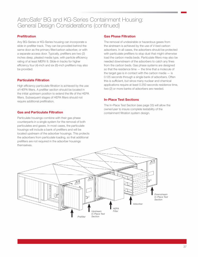
Prefiltration
Any BG-Series or KG-Series housing can incorporate a slide-in prefilter track. They can be provided behind the same door as the primary filter/carbon adsorber, or with a separate access door. Typically, prefilters are two (2) inches deep, pleated media type, with particle efficiency rating of at least MERV 8. Slide-in tracks for higher efficiency four (4)-inch and six (6)-inch prefilters may also be provided.
Particulate Filtration
High efficiency particulate filtration is achieved by the use of HEPA filters. A prefilter section should be located in the initial upstream position to extend the life of the HEPA filters. Subsequent stages of HEPA filters should not require additional prefiltration.
Gas and Particulate Filtration
Particulate housings combine with their gas phase counterparts in a single system for the removal of both particulates and gases. In most cases, the particulate housings will include a bank of prefilters and will be located upstream of the adsorber housings. This protects the adsorbers from particulate loading, so that additional prefilters are not required in the adsorber housings themselves.
Gas Phase Filtration
The removal of undesirable or hazardous gases from the airstream is achieved by the use of V-bed carbon adsorbers. In all cases, the adsorbers should be protected with particulate prefilters to stop dust that might otherwise load the carbon media beds. Particulate filters may also be needed downstream of the adsorbers to catch any fines from the carbon beds. Gas phase systems are designed so that the residence time — the time that a molecule of the target gas is in contact with the carbon media — is 0.125 seconds through a single bank of adsorbers. Often this is sufficient, but since many nuclear and chemical applications require at least 0.250 seconds residence time, two (2) or more banks of adsorbers are needed.
In-Place Test Sections
The In-Place Test Section (see page 33) will allow the owner/user to insure complete testability of the containment filtration system design.
Prefilter
HEPA Filter
Adsorber
Upstream In-Place Test Section
Downstream In-Place Test Section
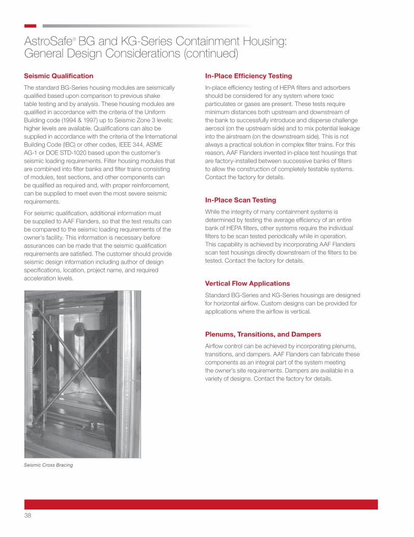
38
AstroSafe® BG and KG-Series Containment Housing: General Design Considerations (continued)
Seismic Qualification
The standard BG-Series housing modules are seismically qualified based upon comparison to previous shake table testing and by analysis. These housing modules are qualified in accordance with the criteria of the Uniform Building code (1994 & 1997) up to Seismic Zone 3 levels; higher levels are available. Qualifications can also be supplied in accordance with the criteria of the International Building Code (IBC) or other codes, IEEE 344, ASME AG-1 or DOE STD-1020 based upon the customer’s seismic loading requirements. Filter housing modules that are combined into filter banks and filter trains consisting of modules, test sections, and other components can be qualified as required and, with proper reinforcement, can be supplied to meet even the most severe seismic requirements.
For seismic qualification, additional information must be supplied to AAF Flanders, so that the test results can be compared to the seismic loading requirements of the owner’s facility. This information is necessary before assurances can be made that the seismic qualification requirements are satisfied. The customer should provide seismic design information including author of design specifications, location, project name, and required acceleration levels.
In-Place Efficiency Testing
In-place efficiency testing of HEPA filters and adsorbers should be considered for any system where toxic particulates or gases are present. These tests require minimum distances both upstream and downstream of the bank to successfully introduce and disperse challenge aerosol (on the upstream side) and to mix potential leakage into the airstream (on the downstream side). This is not always a practical solution in complex filter trains. For this reason, AAF Flanders invented in-place test housings that are factory-installed between successive banks of filters to allow the construction of completely testable systems. Contact the factory for details.
In-Place Scan Testing
While the integrity of many containment systems is determined by testing the average efficiency of an entire bank of HEPA filters, other systems require the individual filters to be scan tested periodically while in operation. This capability is achieved by incorporating AAF Flanders scan test housings directly downstream of the filters to be tested. Contact the factory for details.
Vertical Flow Applications
Standard BG-Series and KG-Series housings are designed for horizontal airflow. Custom designs can be provided for applications where the airflow is vertical.
Plenums, Transitions, and Dampers
Airflow control can be achieved by incorporating plenums, transitions, and dampers. AAF Flanders can fabricate these components as an integral part of the system meeting the owner’s site requirements. Dampers are available in a variety of designs. Contact the factory for details.
Seismic Cross Bracing
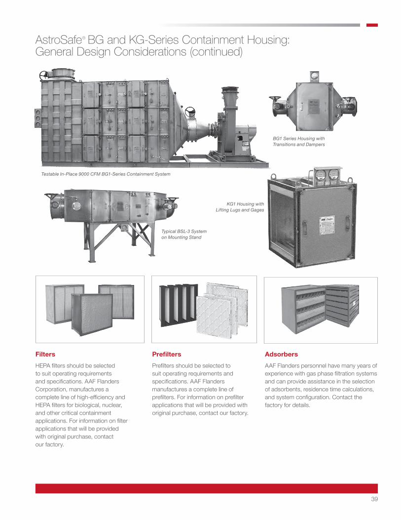
39
AstroSafe® BG and KG-Series Containment Housing: General Design Considerations (continued)
Filters
HEPA filters should be selected to suit operating requirements and specifications. AAF Flanders Corporation, manufactures a complete line of high-efficiency and HEPA filters for biological, nuclear, and other critical containment applications. For information on filter applications that will be provided with original purchase, contact our factory.
Prefilters
Prefilters should be selected to suit operating requirements and specifications. AAF Flanders manufactures a complete line of prefilters. For information on prefilter applications that will be provided with original purchase, contact our factory.
Adsorbers
AAF Flanders personnel have many years of experience with gas phase filtration systems and can provide assistance in the selection of adsorbents, residence time calculations, and system configuration. Contact the factory for details.
Testable In-Place 9000 CFM BG1-Series Containment System
KG1 Housing with Lifting Lugs and Gages
Typical BSL-3 System on Mounting Stand
BG1 Series Housing with Transitions and Dampers
AAF Flanders has a policy of continuous product research and improvement. We reserve the right to change design and specifications without notice.
ISO Certified Firm
©2020 AAF International and its affiliated companies.9920 Corporate Campus Drive, Suite 2200, Louisville, KY 40223-5690
888.223.2003 Fax 888.223.6500 | aafintl.com CSP-3-107 10/20
Important Notice
For best results in the application of AAF Flanders products, it is recommended that the buyer supply complete information about the operating conditions of the ventilation system to AAF Flanders for prior evaluation.
AAF Flanders does not guarantee that its equipment will operate at the performance levels given on the identification labels, or in the catalog specifications under all conditions of installation and use, nor does AAF Flanders guarantee that suitability of its product for the particular end use that may be contemplated by the buyer. When the system components are supplied to the buyer or an agent for final installation and assembly in the field, it should be under the supervision of factory-trained personnel who are equipped to test the installation and certify its performance and conformance to industry-accepted specifications. Failure to follow these procedures may result in a compromised installation.