at commands examples application note wls-cs-11003
TRANSCRIPT
AT Commands Examples Examples for u-blox wireless modules Application Note
Abstract
This document provides detailed examples of how to use AT
commands with u-blox wireless modules.
loca
te,
com
mu
nic
ate
, acc
ele
rate
www.u-blox.com

AT Commands Examples - Application Note
WLS-CS-11003 Page 2 of 51
Document Information
Title AT Commands Examples
Subtitle Examples for
u-blox wireless modules
Document type Application Note
Document number WLS-CS-11003
Document status Preliminary
Document status information
Objective
Specification
This document contains target values. Revised and supplementary data will be published
later.
Advance
Information
This document contains data based on early testing. Revised and supplementary data will
be published later.
Preliminary This document contains data from product verification. Revised and supplementary data
may be published later.
Released This document contains the final product specification.
This document and the use of any information contained therein, is subject to the acceptance of the u-blox terms and conditions. They can be downloaded from www.u-blox.com.
u-blox makes no warranties based on the accuracy or completeness of the contents of this document and reserves the right to make
changes to specifications and product descriptions at any time without notice.
u-blox reserves all rights to this document and the information contained herein. Reproduction, use or disclosure to third parties without
express permission is strictly prohibited. Copyright © 2011, u-blox AG.
AT Commands Examples - Application Note
WLS-CS-11003 Preliminary Page 3 of 51
Contents
Contents .............................................................................................................................. 3
1 Introduction .................................................................................................................. 6
2 Storing parameters ...................................................................................................... 6
3 Network registration and configuration .................................................................... 7
3.1 Steps performed to register the module to a GSM/UMTS network ........................................................ 7
3.1.1 Preliminary operations ................................................................................................................... 7
3.1.2 Network registration: GSM module ............................................................................................... 8
3.1.3 Network registration: UMTS module ............................................................................................. 8
4 GPRS connection......................................................................................................... 12
4.1 Context Activation .............................................................................................................................. 12
4.2 Context Deactivation .......................................................................................................................... 13
4.2.1 Context Deactivation by the network .......................................................................................... 13
4.2.1 Context Deactivation by the module ........................................................................................... 13
5 TCP/IP AT commands .................................................................................................. 13
5.1 Socket Connect .................................................................................................................................. 13
5.2 Socket Listening .................................................................................................................................. 14
5.3 Socket Write ....................................................................................................................................... 14
5.3.1 Binary mode ................................................................................................................................ 14
5.3.2 Base syntax .................................................................................................................................. 15
5.3.3 Queue FULL ................................................................................................................................. 15
5.3.4 GSM network coverage lost ........................................................................................................ 16
5.4 Socket operations with “Keep Alive” option ....................................................................................... 18
5.5 Socket Read ........................................................................................................................................ 19
5.6 Socket State ....................................................................................................................................... 21
5.7 Socket Close ....................................................................................................................................... 21
5.8 Direct Link .......................................................................................................................................... 22
5.8.1 Enter and exit from Direct Link Mode .......................................................................................... 22
5.8.2 Closing a connection ................................................................................................................... 23
5.8.3 Connection closed by remote host .............................................................................................. 23
6 UDP/IP AT commands ................................................................................................. 23
6.1 Socket Write (+USOST) ....................................................................................................................... 23
6.2 Socket Read (+USORF) ........................................................................................................................ 24
6.3 Socket Write (+USOWR) ..................................................................................................................... 25
6.4 Socket Read (+USORD) ....................................................................................................................... 26
7 FTP AT commands ...................................................................................................... 27
AT Commands Examples - Application Note
WLS-CS-11003 Preliminary Page 4 of 51
7.1 Direct Link .......................................................................................................................................... 28
7.1.1 Retrieve a file from FTP server ...................................................................................................... 28
7.1.2 Aborting retrieve file request ....................................................................................................... 29
7.1.3 Store a file on FTP server ............................................................................................................. 29
7.1.4 About “+++” escape sequence usage ......................................................................................... 30
8 SMTP AT commands ................................................................................................... 30
9 HTTP AT commands .................................................................................................... 32
10 Network Congestion Detection AT commands ........................................................ 33
10.1 GSM module................................................................................................................................... 33
11 ADC AT commands (if supported) ............................................................................. 33
12 GPIO AT commands .................................................................................................... 33
13 MUX AT commands .................................................................................................... 34
14 File System AT commands ......................................................................................... 34
15 SIM Toolkit .................................................................................................................. 36
15.1 Profile download ............................................................................................................................. 36
15.2 Proactive SIM .................................................................................................................................. 36
15.3 Example .......................................................................................................................................... 38
15.3.1 Enable the SAT and terminal response ......................................................................................... 38
15.3.2 Changing the terminal profile ...................................................................................................... 38
15.3.3 Entering SAT menu and selecting an item ................................................................................... 39
15.3.4 Call setup .................................................................................................................................... 40
16 SMS AT Commands .................................................................................................... 42
16.1 Read all messages or one single message ........................................................................................ 42
16.2 Delete one single message or multiple messages ............................................................................. 42
16.3 Write and/or send one single message ............................................................................................ 43
16.4 Read all messages or one single message (concatenated SMS related commands) .......................... 44
16.5 Write and/or send a concatenated SMS message ............................................................................ 45
17 SIM Lock AT commands ............................................................................................. 47
17.1 SIM Lock activation and deactivation............................................................................................... 47
17.2 SIM Lock Enabling and Activation ................................................................................................... 47
Appendix .......................................................................................................................... 48
A List of Acronyms ......................................................................................................... 48
Related documents........................................................................................................... 50
AT Commands Examples - Application Note
WLS-CS-11003 Preliminary Page 5 of 51
Revision history ................................................................................................................ 50
Contact .............................................................................................................................. 51
AT Commands Examples - Application Note
WLS-CS-11003 Preliminary Page 6 of 51
1 Introduction This document provides examples of using AT commands. For more details on AT command description please
refer to u-blox AT Commands Manual [1]. The following symbols are used to highlight important information within the document:
An index finger points out key information pertaining to integration and performance.
A warning symbol indicates actions that could negatively impact performance or damage the device.
This document addresses the following products:
LEON-G100 series
LEON-G200 series
LISA-U1/LISA-H1 series
These icons will be used to indicate applicability to the related products:
: LEON-G100 / LEON-G200 series
: LISA-U1/LISA-H1 series
If the subchapter applies to a specific product the related icon will be provided there.
2 Storing parameters
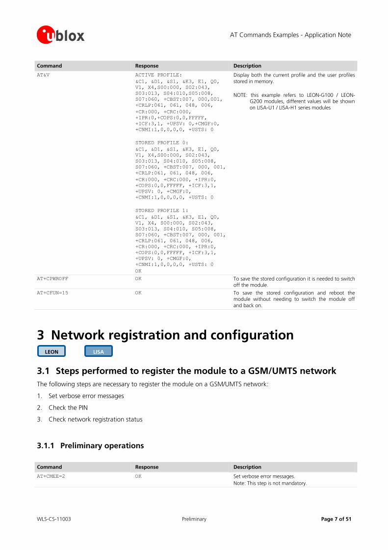
Save parameters in the Non Volatile Memory (NVM). Retrieve parameters from NVM. For further details refer to the command description of AT+CPWROFF, AT&V, AT&W, ATY in the u-blox AT Commands Manual [1].
Command Response Description
AT+CMEE=2 OK Set verbose error messages.
AT&K3 OK Enable RTS/CTS DTE flow control for the current profile.
NOTE: this is the default value saved in profiles 0 and 1. If no changes have been previously done to AT&K values in the stored profiles this step is not mandatory.
AT&Y1 OK Select the default profile that will be automatically loaded after the next hardware reset (in this example profile #1).
AT&W1 OK Store the current settings into profile 1.
LISA LEON
LISA
LEON
AT Commands Examples - Application Note
WLS-CS-11003 Preliminary Page 7 of 51
Command Response Description
AT&V ACTIVE PROFILE:
&C1, &D1, &S1, &K3, E1, Q0,
V1, X4,S00:000, S02:043,
S03:013, S04:010,S05:008,
S07:060, +CBST:007, 000,001,
+CRLP:061, 061, 048, 006,
+CR:000, +CRC:000,
+IPR:0,+COPS:0,0,FFFFF,
+ICF:3,1, +UPSV: 0,+CMGF:0,
+CNMI:1,0,0,0,0, +USTS: 0
STORED PROFILE 0:
&C1, &D1, &S1, &K3, E1, Q0,
V1, X4,S00:000, S02:043,
S03:013, S04:010, S05:008,
S07:060, +CBST:007, 000, 001,
+CRLP:061, 061, 048, 006,
+CR:000, +CRC:000, +IPR:0,
+COPS:0,0,FFFFF, +ICF:3,1,
+UPSV: 0, +CMGF:0,
+CNMI:1,0,0,0,0, +USTS: 0
STORED PROFILE 1:
&C1, &D1, &S1, &K3, E1, Q0,
V1, X4, S00:000, S02:043,
S03:013, S04:010, S05:008,
S07:060, +CBST:007, 000, 001,
+CRLP:061, 061, 048, 006,
+CR:000, +CRC:000, +IPR:0,
+COPS:0,0,FFFFF, +ICF:3,1,
+UPSV: 0, +CMGF:0,
+CNMI:1,0,0,0,0, +USTS: 0
OK
Display both the current profile and the user profiles
stored in memory.
NOTE: this example refers to LEON-G100 / LEON-G200 modules, different values will be shown
on LISA-U1 / LISA-H1 series modules
AT+CPWROFF OK To save the stored configuration it is needed to switch off the module.
AT+CFUN=15 OK To save the stored configuration and reboot the module without needing to switch the module off
and back on.
3 Network registration and configuration
3.1 Steps performed to register the module to a GSM/UMTS network
The following steps are necessary to register the module on a GSM/UMTS network:
1. Set verbose error messages
2. Check the PIN
3. Check network registration status
3.1.1 Preliminary operations
Command Response Description
AT+CMEE=2 OK Set verbose error messages.
Note: This step is not mandatory.
LISA LEON

AT Commands Examples - Application Note
WLS-CS-11003 Preliminary Page 8 of 51
Command Response Description
AT+CPIN? +CPIN: SIM PIN
OK
Check the PIN.
AT+CPIN="1234" OK Define PIN.
AT+CPIN? +CPIN: READY
OK
Check PIN.
Note: OK, the PIN is ready.
3.1.2 Network registration: GSM module
3.1.2.1 Check network registration (first scenario, autoregistration)
Command Response Description
AT+COPS? +COPS: 0,0,"vodafone IT"
OK
Check network registration status.
Note: OK, the module is registered to GSM service.
AT+CGATT? +CGATT: 1
OK
Check GPRS attach status.
Note: OK, the module is GPRS attached.
3.1.2.2 Check network registration (second scenario, without autoregistration)
Command Response Description
AT+COPS? +COPS: 2
OK
Check network registration status.
Note: OK, the module is not registered to GSM
service.
AT+COPS=0 OK Force network registration.
AT+COPS? +COPS: 0,0,"vodafone IT"
OK
Check network registration status.
Note: OK, the module is registered to GSM service.
3.1.2.3 GSM Band change
Command Response Description
AT+UBANDSEL? +UBANDSEL: 900, 1800 Check the current selected GSM bands
AT+COPS=2 OK Force network deregistration if the module was
previously registered or registration is pending.
AT+UBANDSEL=850,1900 OK Change the operating GSM bands
Note: the new configuration is saved in NVM for
future registration attempts
AT+COPS=0 OK Force network registration.
3.1.3 Network registration: UMTS module
3.1.3.1 Preliminary information about Radio Access Technology (RAT) configuration
Default RAT configuration is GSM / UMTS Dual Mode with UMTS preferred access technology.
LISA
LEON

AT Commands Examples - Application Note
WLS-CS-11003 Preliminary Page 9 of 51
Command Response Description
AT+URAT? +URAT: 1,2
OK
The Default RAT configuration is GSM / UMTS Dual mode Radio Access technology with UMTS preferred access technology. With this configuration the module can access both GSM and UMTS networks, UMTS
networks are preferred.
Any change in the RAT selection has to be done when the module is deregistered from the network. Before changing the RAT deregister the module with AT+COPS=2 command.
After changing the RAT configuration to ensure that the new settings are saved in the NVM it’s
necessary to power off the module (AT+CPWROFF). Then switch on the module and repeat the steps listed in chapter 3.1.1.
When a new RAT setting is saved in the NVM it’s not possible to load the RAT factory defined
configuration. You can restore this by performing the following steps:
Command Response Description
AT+COPS=2 OK Deregister the module from the network. This operation must only be performed if the module is
registered on the network.
AT+URAT=1,2 OK Select GSM / UMTS Dual mode Radio Access technology with UMTS networks preferred.
This is the RAT factory defined configuration.
AT+CPWROFF OK Switch off the module.
3.1.3.2 Selection of Radio Access technology
GSM Single Mode Radio Access technology
Command Response Description
AT+URAT=0,0 OK Select GSM Single Mode Radio Access technology.
AT+URAT? +URAT: 0,0
OK
With this configuration the module can access only GSM networks.
AT+COPS=0 OK Start automatic network registration.
AT+COPS? +COPS: 0,0,"vodafone IT",0
OK
Check network registration status.
Last parameter (0 in this case) indicates the module is registered to GSM service (as expected considering that module is not allowed to access to UMTS networks).
GSM / UMTS Dual mode Radio Access technology
Command Response Description
AT+URAT=1,0 OK Select GSM / UMTS Dual mode Radio Access technology. GSM is the preferred access technology.
AT+URAT? +URAT: 1,0
OK
With this configuration the module can access both GSM and UMTS networks, GSM networks are preferred.
AT+URAT=1,2 OK Select GSM / UMTS Dual mode Radio Access technology. UMTS is the preferred access technology.
AT+URAT? +URAT: 1,2
OK
With this configuration the module can access both GSM and UMTS networks, UMTS networks are
preferred.
AT+COPS=0 OK Start automatic network registration.

AT Commands Examples - Application Note
WLS-CS-11003 Preliminary Page 10 of 51
Command Response Description
AT+COPS? +COPS: 0,0,"vodafone IT",2
OK
Check network registration status.
Last parameter (2 in this case) indicates the module is registered to UMTS service.
AT+COPS? +COPS: 0,0,"vodafone IT",0
OK
Module is also allowed to access GSM networks.
This will be the module response if it has registered to GSM service.
UMTS Single Mode Radio Access technology
Command Response Description
AT+URAT=2,2 OK Select UMTS Single Mode Radio Access technology.
AT+URAT? +URAT: 2,2
OK
With this configuration the module can access only UMTS networks.
AT+COPS=0 OK Start automatic network registration.
AT+COPS? +COPS: 0,0,"vodafone IT",2
OK
Check network registration status.
Last parameter (2 in this case) indicates the module is registered to UMTS service (as expected considering that module is not allowed to access to GSM networks).
If the module is registered in GSM / UMTS Dual Mode (AT+URAT=1,0 or AT+URAT=1,2) it is possible
to change preferred RAT technology but the new setting will take effect only after a period of lost network coverage or if the module is deregistered and registered again on the network.
Command Response Description
AT+URAT=1,0 OK Select GSM / UMTS Dual mode Radio Access technology. GSM is the preferred access technology.
AT+URAT? +URAT: 1,0
OK
With this configuration the module can access both GSM and UMTS networks, GSM networks are
preferred.
AT+COPS=0 OK Start automatic network registration.
AT+COPS? +COPS: 0,0,"vodafone IT",0
OK
Check network registration status.
Last parameter (0 in this case) indicates the module is registered to GSM service.
AT+URAT=1,2 OK Select GSM / UMTS Dual mode Radio Access technology. UMTS is the preferred access technology.
AT+URAT? +URAT: 1,2
OK
With this configuration the module can access both GSM and UMTS networks, UMTS networks are preferred.
AT+COPS? +COPS: 0,0,"vodafone IT",0
OK
Last parameter (0 in this case) indicates the module is still registered to GSM service although UMTS is now the preferred access technology.
AT+COPS=2 OK Deregister the module from the network.
AT+COPS=0 OK Start automatic network registration.
AT+COPS? +COPS: 0,0,"vodafone IT",2
OK
Last parameter (2 in this case) indicates the module is registered to UMTS service.
Note: this is only an example. Remember that with URAT=1,2 UMTS is the preferred and not the only allowed RAT. If the UMTS network coverage is weak the module will register again on GSM network.
AT Commands Examples - Application Note
WLS-CS-11003 Preliminary Page 11 of 51
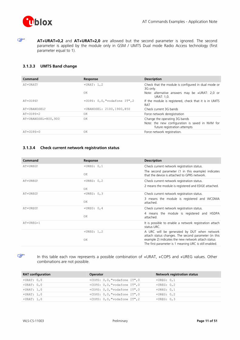
AT+URAT=0,2 and AT+URAT=2,0 are allowed but the second parameter is ignored. The second parameter is applied by the module only in GSM / UMTS Dual mode Radio Access technology (first
parameter equal to 1).
3.1.3.3 UMTS Band change
Command Response Description
AT+URAT?
AT+COPS?
AT+UBANDSEL?
+URAT: 1,2
OK
+COPS: 0,0,"vodafone IT",2
+UBANDSEL: 2100,1900,850
Check that the module is configured in dual mode or
3G only.
Note: alternative answers may be +URAT: 2,0 or URAT: 1,0.
If the module is registered, check that it is in UMTS
RAT
Check current 3G bands
AT+COPS=2 OK Force network deregistration
AT+UBANDSEL=800,900 OK Change the operating 3G bands
Note: the new configuration is saved in NVM for
future registration attempts
AT+COPS=0 OK Force network registration.
3.1.3.4 Check current network registration status
Command Response Description
AT+UREG? +UREG: 0,1
OK
Check current network registration status.
The second parameter (1 in this example) indicates that the device is attached to GPRS network.
AT+UREG? +UREG: 0,2
OK
Check current network registration status.
2 means the module is registered and EDGE attached.
AT+UREG? +UREG: 0,3
OK
Check current network registration status.
3 means the module is registered and WCDMA attached.
AT+UREG? +UREG: 0,4
OK
Check current network registration status.
4 means the module is registered and HSDPA attached.
AT+UREG=1 It is possible to enable a network registration attach status URC.
+UREG: 1,2
OK
A URC will be generated by DUT when network attach status changes. The second parameter (in this
example 2) indicates the new network attach status
The first parameter is 1 meaning URC is still enabled.
In this table each row represents a possible combination of +URAT, +COPS and +UREG values. Other
combinations are not possible.
RAT configuration Operator Network registration status
+URAT: 0,0 +COPS: 0,0,"vodafone IT",0 +UREG: 0,1
+URAT: 0,0 +COPS: 0,0,"vodafone IT",0 +UREG: 0,2
+URAT: 1,0 +COPS: 0,0,"vodafone IT",0 +UREG: 0,1
+URAT: 1,0 +COPS: 0,0,"vodafone IT",0 +UREG: 0,2
+URAT: 1,0 +COPS: 0,0,"vodafone IT",2 +UREG: 0,3
AT Commands Examples - Application Note
WLS-CS-11003 Preliminary Page 12 of 51
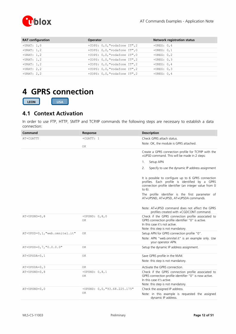
RAT configuration Operator Network registration status
+URAT: 1,0 +COPS: 0,0,"vodafone IT",2 +UREG: 0,4
+URAT: 1,2 +COPS: 0,0,"vodafone IT",0 +UREG: 0,1
+URAT: 1,2 +COPS: 0,0,"vodafone IT",0 +UREG: 0,2
+URAT: 1,2 +COPS: 0,0,"vodafone IT",2 +UREG: 0,3
+URAT: 1,2 +COPS: 0,0,"vodafone IT",2 +UREG: 0,4
+URAT: 2,2 +COPS: 0,0,"vodafone IT",2 +UREG: 0,3
+URAT: 2,2 +COPS: 0,0,"vodafone IT",2 +UREG: 0,4
4 GPRS connection
4.1 Context Activation
In order to use FTP, HTTP, SMTP and TCP/IP commands the following steps are necessary to establish a data connection:
Command Response Description
AT+CGATT? +CGATT: 1
OK
Check GPRS attach status.
Note: OK, the module is GPRS attached.
Create a GPRS connection profile for TCP/IP with the +UPSD command. This will be made in 2 steps:
1. Setup APN
2. Specify to use the dynamic IP address assignment
It is possible to configure up to 6 GPRS connection profiles. Each profile is identified by a GPRS connection profile identifier (an integer value from 0 to 6).
The profile identifier is the first parameter of AT+UPSND, AT+UPSD, AT+UPSDA commands.
Note: AT+UPSD command does not affect the GPRS profiles created with +CGDCONT command.
AT+UPSND=0,8 +UPSND: 0,8,0
OK
Check if the GPRS connection profile associated to GPRS connection profile identifier “0” is active.
In this case it’s not active.
Note: this step is not mandatory.
AT+UPSD=0,1,"web.omnitel.it" OK Setup APN for GPRS connection profile “0”.
Note: APN "web.omnitel.it" is an example only. Use your operator APN.
AT+UPSD=0,7,"0.0.0.0" OK
Setup the dynamic IP address assignment.
AT+UPSDA=0,1 OK Save GPRS profile in the NVM.
Note: this step is not mandatory.
AT+UPSDA=0,3 OK Activate the GPRS connection.
AT+UPSND=0,8 +UPSND: 0,8,1
OK
Check if the GPRS connection profile associated to GPRS connection profile identifier “0” is now active.
In this case it’s active.
Note: this step is not mandatory.
AT+UPSND=0,0 +UPSND: 0,0,"93.68.225.175"
OK
Check the assigned IP address.
Note: in this example is requested the assigned dynamic IP address.
LISA LEON
AT Commands Examples - Application Note
WLS-CS-11003 Preliminary Page 13 of 51
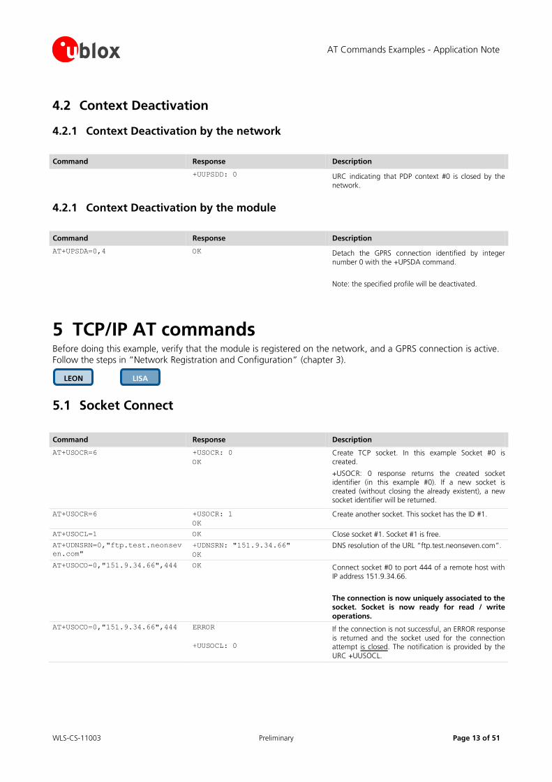
4.2 Context Deactivation
4.2.1 Context Deactivation by the network
Command Response Description
+UUPSDD: 0 URC indicating that PDP context #0 is closed by the network.
4.2.1 Context Deactivation by the module
Command Response Description
AT+UPSDA=0,4 OK Detach the GPRS connection identified by integer number 0 with the +UPSDA command.
Note: the specified profile will be deactivated.
5 TCP/IP AT commands Before doing this example, verify that the module is registered on the network, and a GPRS connection is active.
Follow the steps in “Network Registration and Configuration” (chapter 3).
5.1 Socket Connect
Command Response Description
AT+USOCR=6 +USOCR: 0
OK
Create TCP socket. In this example Socket #0 is created.
+USOCR: 0 response returns the created socket identifier (in this example #0). If a new socket is created (without closing the already existent), a new socket identifier will be returned.
AT+USOCR=6 +USOCR: 1
OK
Create another socket. This socket has the ID #1.
AT+USOCL=1 OK Close socket #1. Socket #1 is free.
AT+UDNSRN=0,"ftp.test.neonsev
en.com"
+UDNSRN: "151.9.34.66"
OK
DNS resolution of the URL “ftp.test.neonseven.com”.
AT+USOCO=0,"151.9.34.66",444 OK Connect socket #0 to port 444 of a remote host with IP address 151.9.34.66.
The connection is now uniquely associated to the socket. Socket is now ready for read / write
operations.
AT+USOCO=0,"151.9.34.66",444 ERROR
+UUSOCL: 0
If the connection is not successful, an ERROR response is returned and the socket used for the connection attempt is closed. The notification is provided by the URC +UUSOCL.
LISA LEON

AT Commands Examples - Application Note
WLS-CS-11003 Preliminary Page 14 of 51
5.2 Socket Listening
Command Response Description
AT+USOCR=6 +USOCR: 0
OK
Create a TCP socket with ID #0.
AT+USOLI=0,1099 OK Set socket in listening mode on port 1099.
WARNING: The ability to reach the opened port on the server depends also on the network operator. Some network operators will not allow
incoming connection on opened TCP port.
+UUSOLI:
1,"151.9.34.66",39912,0,
"151.9.34.74",1099
When a connections request arrives from a remote host, a new socket is created with the first integer identifier available. In this example socket ID is #1.
+UUSOLI indicates:
1: the new socket created.. Incoming data from the established connection will be received on this socket. Data to be sent over the connection must be written into this socket
151.9.34.66: IP of the remote server
39912: port of service
0: listening socket. It is the socket identifier specified with the AT+USOLI command
151.9.34.74: IP address of the module
1099: listening port assigned to the connection. Returned with AT+USOLI command
Socket #1 is now ready for reading/writing data +UUSORD: 1,18 18 bytes of incoming data over the previously
established connection.
Note that data arrives on socket identified by integer number 1 not on socket identified by integer number 0. The incoming data will be sent always on the related socket.
5.3 Socket Write
5.3.1 Binary mode
Command Response Description
AT+USOWR=0,2 @ Request to write 2 data bytes into socket #0. Wait “@” symbol indicating the data prompt is now open (AT commands are not allowed in data prompt).
AT Commands Examples - Application Note
WLS-CS-11003 Preliminary Page 15 of 51
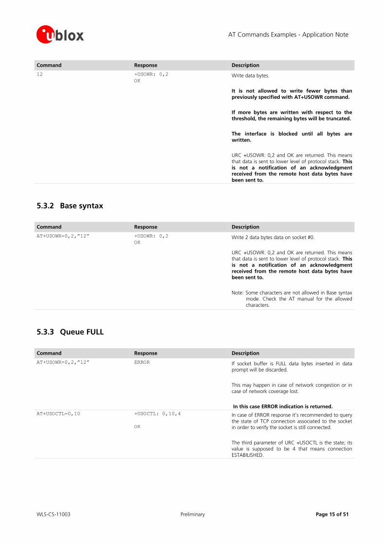
Command Response Description
12 +USOWR: 0,2
OK Write data bytes.
It is not allowed to write fewer bytes than previously specified with AT+USOWR command.
If more bytes are written with respect to the threshold, the remaining bytes will be truncated.
The interface is blocked until all bytes are written.
URC +USOWR: 0,2 and OK are returned. This means that data is sent to lower level of protocol stack. This is not a notification of an acknowledgment received from the remote host data bytes have been sent to.
5.3.2 Base syntax
Command Response Description
AT+USOWR=0,2,”12” +USOWR: 0,2
OK Write 2 data bytes data on socket #0.
URC +USOWR: 0,2 and OK are returned. This means that data is sent to lower level of protocol stack. This is not a notification of an acknowledgment received from the remote host data bytes have been sent to.
Note: Some characters are not allowed in Base syntax mode. Check the AT manual for the allowed characters.
5.3.3 Queue FULL
Command Response Description
AT+USOWR=0,2,”12” ERROR If socket buffer is FULL data bytes inserted in data prompt will be discarded.
This may happen in case of network congestion or in case of network coverage lost.
In this case ERROR indication is returned.
AT+USOCTL=0,10 +USOCTL: 0,10,4
OK
In case of ERROR response it’s recommended to query the state of TCP connection associated to the socket in order to verify the socket is still connected.
The third parameter of URC +USOCTL is the state; its value is supposed to be 4 that means connection ESTABILISHED.
AT Commands Examples - Application Note
WLS-CS-11003 Preliminary Page 16 of 51
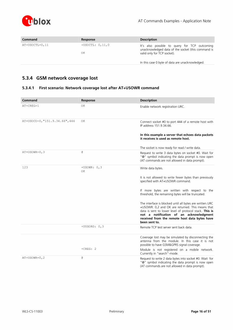
Command Response Description
AT+USOCTL=0,11 +USOCTL: 0,11,0
OK
It’s also possible to query for TCP outcoming unacknowledged data of the socket (this command is valid only for TCP socket).
In this case 0 byte of data are unacknowledged.
5.3.4 GSM network coverage lost
5.3.4.1 First scenario: Network coverage lost after AT+USOWR command
Command Response Description
AT+CREG=1 OK Enable network registration URC.
AT+USOCO=0,"151.9.34.66",444 OK Connect socket #0 to port 444 of a remote host with IP address 151.9.34.66.
In this example a server that echoes data packets it receives is used as remote host.
The socket is now ready for read / write data.
AT+USOWR=0,3 @ Request to write 3 data bytes on socket #0. Wait for “@” symbol indicating the data prompt is now open (AT commands are not allowed in data prompt).
123 +USOWR: 0,3
OK Write data bytes.
It is not allowed to write fewer bytes than previously specified with AT+USOWR command.
If more bytes are written with respect to the threshold, the remaining bytes will be truncated.
The interface is blocked until all bytes are written.URC +USOWR: 0,2 and OK are returned. This means that data is sent to lower level of protocol stack. This is not a notification of an acknowledgment received from the remote host data bytes have been sent to.
+UUSORD: 0,3 Remote TCP test server sent back data.
Coverage lost may be simulated by disconnecting the antenna from the module. In this case it is not possible to have GSM&GPRS signal coverage.
+CREG: 2 Module is not registered on a mobile network. Currently in “search”-mode.
AT+USOWR=0,2 @ Request to write 2 data bytes into socket #0. Wait for “@” symbol indicating the data prompt is now open (AT commands are not allowed in data prompt).
AT Commands Examples - Application Note
WLS-CS-11003 Preliminary Page 17 of 51
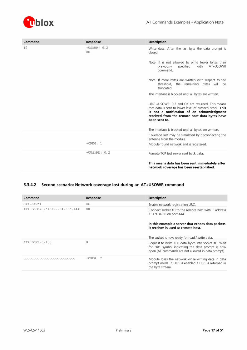
Command Response Description
12 +USOWR: 0,2
OK Write data. After the last byte the data prompt is closed.
Note: It is not allowed to write fewer bytes than previously specified with AT+USOWR command.
Note: If more bytes are written with respect to the threshold, the remaining bytes will be truncated.
The interface is blocked until all bytes are written.
URC +USOWR: 0,2 and OK are returned. This means that data is sent to lower level of protocol stack. This is not a notification of an acknowledgment received from the remote host data bytes have been sent to.
The interface is blocked until all bytes are written.
Coverage lost may be simulated by disconnecting the antenna from the module.
+CREG: 1 Module found network and is registered.
+UUSORD: 0,2 Remote TCP test server sent back data.
This means data has been sent immediately after network coverage has been reestablished.
5.3.4.2 Second scenario: Network coverage lost during an AT+USOWR command
Command Response Description
AT+CREG=1 OK Enable network registration URC.
AT+USOCO=0,"151.9.34.66",444 OK Connect socket #0 to the remote host with IP address 151.9.34.66 on port 444.
In this example a server that echoes data packets it receives is used as remote host.
The socket is now ready for read / write data.
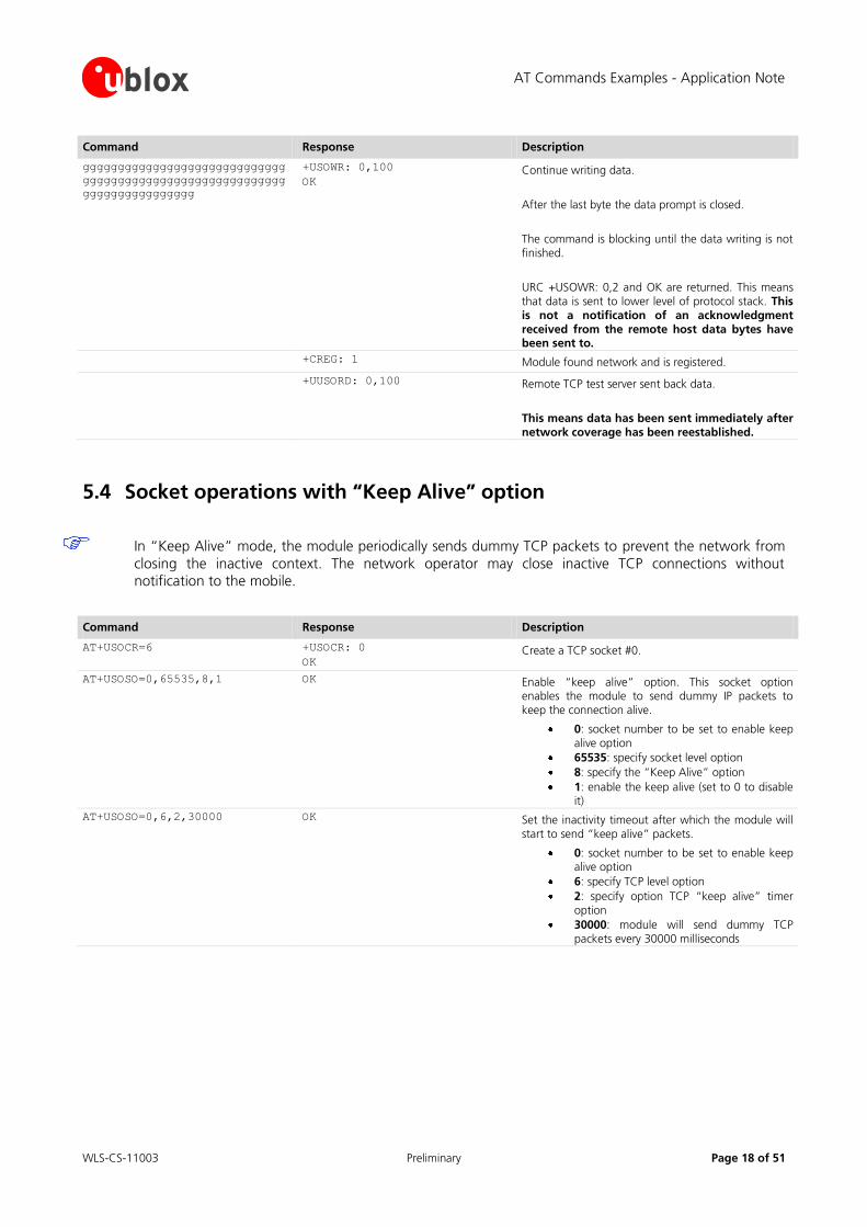
AT+USOWR=0,100 @ Request to write 100 data bytes into socket #0. Wait for “@” symbol indicating the data prompt is now open (AT commands are not allowed in data prompt).
gggggggggggggggggggggggggg +CREG: 2 Module loses the network while writing data in data prompt mode. If URC is enabled a URC is returned in the byte stream.
AT Commands Examples - Application Note
WLS-CS-11003 Preliminary Page 18 of 51
Command Response Description
ggggggggggggggggggggggggggggg
ggggggggggggggggggggggggggggg
gggggggggggggggg
+USOWR: 0,100
OK Continue writing data.
After the last byte the data prompt is closed.
The command is blocking until the data writing is not finished.
URC +USOWR: 0,2 and OK are returned. This means that data is sent to lower level of protocol stack. This is not a notification of an acknowledgment received from the remote host data bytes have been sent to.
+CREG: 1 Module found network and is registered.
+UUSORD: 0,100 Remote TCP test server sent back data.
This means data has been sent immediately after network coverage has been reestablished.
5.4 Socket operations with “Keep Alive” option
In “Keep Alive” mode, the module periodically sends dummy TCP packets to prevent the network from
closing the inactive context. The network operator may close inactive TCP connections without notification to the mobile.
Command Response Description
AT+USOCR=6 +USOCR: 0
OK Create a TCP socket #0.
AT+USOSO=0,65535,8,1 OK Enable “keep alive” option. This socket option enables the module to send dummy IP packets to keep the connection alive.
0: socket number to be set to enable keep alive option
65535: specify socket level option
8: specify the “Keep Alive” option
1: enable the keep alive (set to 0 to disable it)
AT+USOSO=0,6,2,30000 OK Set the inactivity timeout after which the module will start to send “keep alive” packets.
0: socket number to be set to enable keep alive option
6: specify TCP level option
2: specify option TCP “keep alive” timer option
30000: module will send dummy TCP packets every 30000 milliseconds

AT Commands Examples - Application Note
WLS-CS-11003 Preliminary Page 19 of 51
5.5 Socket Read
First scenario
Command Response Description
+UUSORD: 0,2
Remote server sends 2 data bytes on socket #0.
A URC is returned indicating the socket on which the data is received and the total amount of data received.
AT+USORD=0,2 +USORD: 0,2,"ar"
OK Read data. Data is returned between quotation marks.
Second scenario
Command Response Description
+UUSORD: 0,30
Remote server sends 30 data bytes on socket #0.
If a socket buffer is empty URC +UUSORD indicates a TCP packet has been received from the remote host the socket is connected to and the amount of data bytes of the packet.
AT+USORD=0,10 +USORD: 0,10,"hfgyrhgfty"
OK
+UUSORD: 0,20
Read only part of data (in this example 10 bytes of data are read).
Data is returned between quotation marks.
URC +UUSORD indicates the total amount of data bytes stored in the buffer after last AT+USORD execution. In this example 20 bytes are stored in the buffer.
Third scenario
Command Response Description
+UUSORD: 0,30
Remote server sends 30 data bytes on socket #0.
If a socket buffer is empty URC +UUSORD indicates a TCP packet has been received from the remote host the socket is connected to and the amount of data bytes of the packet.
AT+USORD=0,10 +USORD: 0,10,"hfgyrhgfty"
OK
+UUSORD: 0,25
Only part of the data bytes (in this example 10 bytes) are read.
Data is returned between quotation marks.
Remote server sent more data after the first part was received. URC +UUSORD indicates the total amount of data bytes stored the buffer after the last AT+USORD execution. In this example 25 bytes are stored in the buffer.
AT+USORD=0,10 +USORD: 0,10,"hfgbchs7[o"
OK
+UUSORD: 0,34
Only part of the data bytes (in this example 10 bytes) are read.
Data is returned between quotation marks.
Remote server sent more data. URC +UUSORD indicates the total amount of data bytes stored the buffer after the last AT+USORD execution. In this example 34 bytes are stored in the buffer.
AT Commands Examples - Application Note
WLS-CS-11003 Preliminary Page 20 of 51
Command Response Description
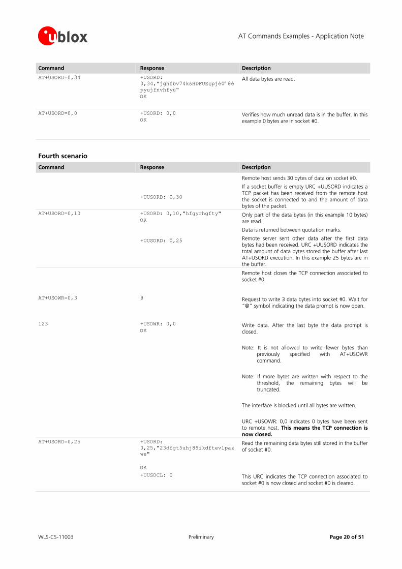
AT+USORD=0,34 +USORD:
0,34,"jghfbv74ksHDFUEçpjè0’@è
pyujfnvhfyù"
OK
All data bytes are read.
AT+USORD=0,0 +USORD: 0,0
OK Verifies how much unread data is in the buffer. In this example 0 bytes are in socket #0.
Fourth scenario
Command Response Description
+UUSORD: 0,30
Remote host sends 30 bytes of data on socket #0.
If a socket buffer is empty URC +UUSORD indicates a TCP packet has been received from the remote host the socket is connected to and the amount of data bytes of the packet.
AT+USORD=0,10 +USORD: 0,10,"hfgyrhgfty"
OK
+UUSORD: 0,25
Only part of the data bytes (in this example 10 bytes) are read.
Data is returned between quotation marks.
Remote server sent other data after the first data bytes had been received. URC +UUSORD indicates the total amount of data bytes stored the buffer after last AT+USORD execution. In this example 25 bytes are in the buffer.
Remote host closes the TCP connection associated to socket #0.
AT+USOWR=0,3 @ Request to write 3 data bytes into socket #0. Wait for “@” symbol indicating the data prompt is now open.
123 +USOWR: 0,0
OK Write data. After the last byte the data prompt is closed.
Note: It is not allowed to write fewer bytes than previously specified with AT+USOWR command.
Note: If more bytes are written with respect to the threshold, the remaining bytes will be truncated.
The interface is blocked until all bytes are written.
URC +USOWR: 0,0 indicates 0 bytes have been sent to remote host. This means the TCP connection is now closed.
AT+USORD=0,25 +USORD:
0,25,"23dfgt5uhj89ikdftevlpaz
we"
OK
Read the remaining data bytes still stored in the buffer of socket #0.
+UUSOCL: 0 This URC indicates the TCP connection associated to socket #0 is now closed and socket #0 is cleared.
AT Commands Examples - Application Note
WLS-CS-11003 Preliminary Page 21 of 51
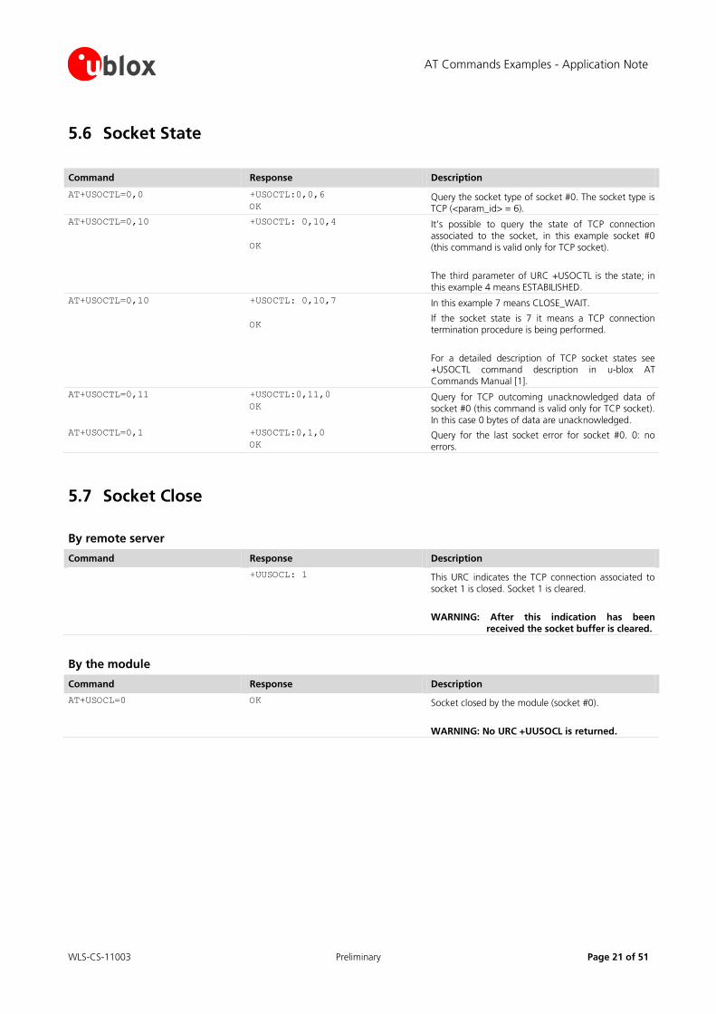
5.6 Socket State
Command Response Description
AT+USOCTL=0,0 +USOCTL:0,0,6
OK Query the socket type of socket #0. The socket type is TCP (<param_id> = 6).
AT+USOCTL=0,10 +USOCTL: 0,10,4
OK
It’s possible to query the state of TCP connection associated to the socket, in this example socket #0 (this command is valid only for TCP socket).
The third parameter of URC +USOCTL is the state; in this example 4 means ESTABILISHED.
AT+USOCTL=0,10 +USOCTL: 0,10,7
OK
In this example 7 means CLOSE_WAIT.
If the socket state is 7 it means a TCP connection termination procedure is being performed.
For a detailed description of TCP socket states see +USOCTL command description in u-blox AT Commands Manual [1].
AT+USOCTL=0,11 +USOCTL:0,11,0
OK Query for TCP outcoming unacknowledged data of socket #0 (this command is valid only for TCP socket). In this case 0 bytes of data are unacknowledged.
AT+USOCTL=0,1 +USOCTL:0,1,0
OK Query for the last socket error for socket #0. 0: no errors.
5.7 Socket Close
By remote server
Command Response Description
+UUSOCL: 1 This URC indicates the TCP connection associated to socket 1 is closed. Socket 1 is cleared.
WARNING: After this indication has been received the socket buffer is cleared.
By the module
Command Response Description
AT+USOCL=0 OK Socket closed by the module (socket #0).
WARNING: No URC +UUSOCL is returned.
AT Commands Examples - Application Note
WLS-CS-11003 Preliminary Page 22 of 51
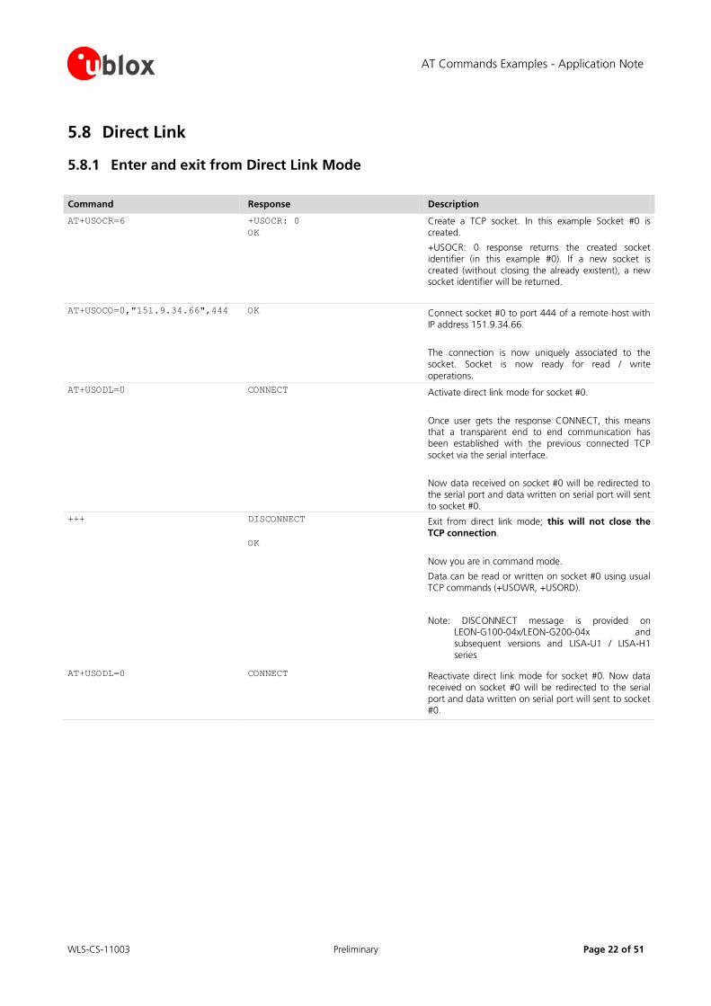
5.8 Direct Link
5.8.1 Enter and exit from Direct Link Mode
Command Response Description
AT+USOCR=6 +USOCR: 0
OK
Create a TCP socket. In this example Socket #0 is created.
+USOCR: 0 response returns the created socket identifier (in this example #0). If a new socket is created (without closing the already existent), a new socket identifier will be returned.
AT+USOCO=0,"151.9.34.66",444 OK Connect socket #0 to port 444 of a remote host with IP address 151.9.34.66.
The connection is now uniquely associated to the socket. Socket is now ready for read / write
operations.
AT+USODL=0 CONNECT Activate direct link mode for socket #0.
Once user gets the response CONNECT, this means that a transparent end to end communication has been established with the previous connected TCP socket via the serial interface.
Now data received on socket #0 will be redirected to the serial port and data written on serial port will sent to socket #0.
+++ DISCONNECT
OK
Exit from direct link mode; this will not close the TCP connection.
Now you are in command mode.
Data can be read or written on socket #0 using usual TCP commands (+USOWR, +USORD).
Note: DISCONNECT message is provided on LEON-G100-04x/LEON-G200-04x and subsequent versions and LISA-U1 / LISA-H1 series
AT+USODL=0 CONNECT Reactivate direct link mode for socket #0. Now data received on socket #0 will be redirected to the serial port and data written on serial port will sent to socket #0.
AT Commands Examples - Application Note
WLS-CS-11003 Preliminary Page 23 of 51
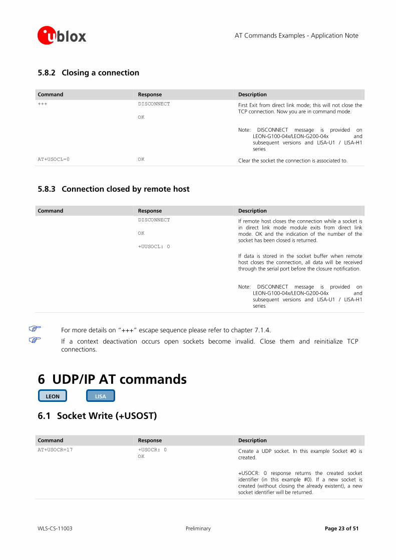
5.8.2 Closing a connection
Command Response Description
+++ DISCONNECT
OK
First Exit from direct link mode; this will not close the TCP connection. Now you are in command mode.
Note: DISCONNECT message is provided on LEON-G100-04x/LEON-G200-04x and subsequent versions and LISA-U1 / LISA-H1 series
AT+USOCL=0 OK Clear the socket the connection is associated to.
5.8.3 Connection closed by remote host
Command Response Description
DISCONNECT
OK
+UUSOCL: 0
If remote host closes the connection while a socket is in direct link mode module exits from direct link mode. OK and the indication of the number of the socket has been closed is returned.
If data is stored in the socket buffer when remote host closes the connection, all data will be received through the serial port before the closure notification.
Note: DISCONNECT message is provided on LEON-G100-04x/LEON-G200-04x and subsequent versions and LISA-U1 / LISA-H1 series
For more details on “+++” escape sequence please refer to chapter 7.1.4.
If a context deactivation occurs open sockets become invalid. Close them and reinitialize TCP
connections.
6 UDP/IP AT commands
6.1 Socket Write (+USOST)
Command Response Description
AT+USOCR=17 +USOCR: 0
OK Create a UDP socket. In this example Socket #0 is created.
+USOCR: 0 response returns the created socket identifier (in this example #0). If a new socket is created (without closing the already existent), a new socket identifier will be returned.
LISA LEON
AT Commands Examples - Application Note
WLS-CS-11003 Preliminary Page 24 of 51
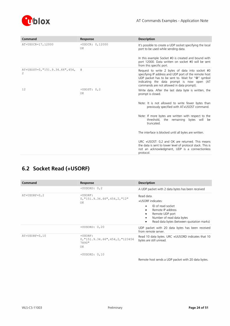
Command Response Description
AT+USOCR=17,12000 +USOCR: 0,12000
OK It’s possible to create a UDP socket specifying the local port to be used while sending data.
In this example Socket #0 is created and bound with port 12000. Data written on socket #0 will be sent from this specific port.
AT+USOST=0,"151.9.34.66",454,
2
@ Request to write 2 bytes of data into socket #0 specifying IP address and UDP port of the remote host UDP packet has to be sent to. Wait for “@” symbol indicating the data prompt is now open (AT commands are not allowed in data prompt).
12 +USOST: 0,2
OK Write data. After the last data byte is written, the prompt is closed.
Note: It is not allowed to write fewer bytes than previously specified with AT+USOST command.
Note: If more bytes are written with respect to the threshold, the remaining bytes will be truncated.
The interface is blocked until all bytes are written.
URC +USOST: 0,2 and OK are returned. This means the data is sent to lower level of protocol stack. This is not an acknowledgment, UDP is a connectionless protocol.
6.2 Socket Read (+USORF)
Command Response Description
+UUSORD: 0,2 A UDP packet with 2 data bytes has been received
AT+USORF=0,2 +USORF:
0,"151.9.34.66",454,2,"12"
OK
Read data.
+USORF indicates:
ID of read socket
Remote IP address
Remote UDP port
Number of read data bytes
Read data bytes (between quotation marks)
+UUSORD: 0,20 UDP packet with 20 data bytes has been received from remote server.
AT+USORF=0,10 +USORF:
0,"151.9.34.66",454,2,"123456
7890"
OK
+UUSORD: 0,10
Read 10 data bytes. URC +UUSORD indicates that 10 bytes are still unread.
Remote host sends a UDP packet with 20 data bytes.
AT Commands Examples - Application Note
WLS-CS-11003 Preliminary Page 25 of 51
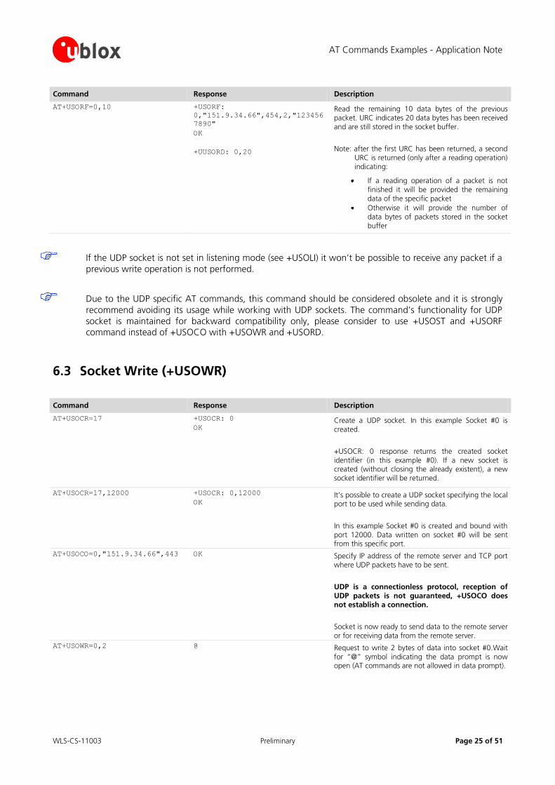
Command Response Description
AT+USORF=0,10 +USORF:
0,"151.9.34.66",454,2,"123456
7890"
OK
+UUSORD: 0,20
Read the remaining 10 data bytes of the previous packet. URC indicates 20 data bytes has been received and are still stored in the socket buffer.
Note: after the first URC has been returned, a second URC is returned (only after a reading operation) indicating:
If a reading operation of a packet is not finished it will be provided the remaining data of the specific packet
Otherwise it will provide the number of data bytes of packets stored in the socket buffer
If the UDP socket is not set in listening mode (see +USOLI) it won’t be possible to receive any packet if a
previous write operation is not performed.
Due to the UDP specific AT commands, this command should be considered obsolete and it is strongly
recommend avoiding its usage while working with UDP sockets. The command’s functionality for UDP
socket is maintained for backward compatibility only, please consider to use +USOST and +USORF command instead of +USOCO with +USOWR and +USORD.
6.3 Socket Write (+USOWR)
Command Response Description
AT+USOCR=17 +USOCR: 0
OK Create a UDP socket. In this example Socket #0 is created.
+USOCR: 0 response returns the created socket identifier (in this example #0). If a new socket is created (without closing the already existent), a new socket identifier will be returned.
AT+USOCR=17,12000 +USOCR: 0,12000
OK It’s possible to create a UDP socket specifying the local port to be used while sending data.
In this example Socket #0 is created and bound with port 12000. Data written on socket #0 will be sent from this specific port.
AT+USOCO=0,"151.9.34.66",443 OK Specify IP address of the remote server and TCP port where UDP packets have to be sent.
UDP is a connectionless protocol, reception of UDP packets is not guaranteed, +USOCO does not establish a connection.
Socket is now ready to send data to the remote server or for receiving data from the remote server.
AT+USOWR=0,2 @ Request to write 2 bytes of data into socket #0.Wait for “@” symbol indicating the data prompt is now open (AT commands are not allowed in data prompt).
AT Commands Examples - Application Note
WLS-CS-11003 Preliminary Page 26 of 51
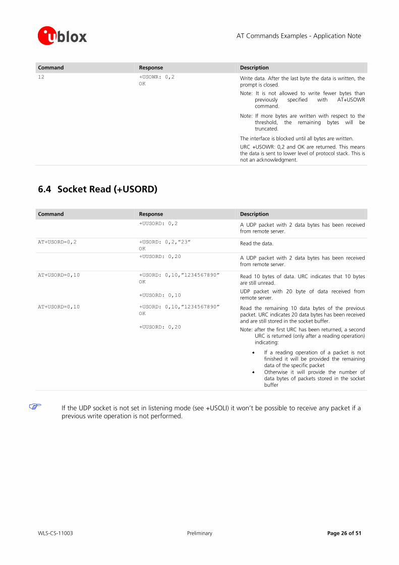
Command Response Description
12 +USOWR: 0,2
OK Write data. After the last byte the data is written, the prompt is closed.
Note: It is not allowed to write fewer bytes than previously specified with AT+USOWR command.
Note: If more bytes are written with respect to the threshold, the remaining bytes will be truncated.
The interface is blocked until all bytes are written.
URC +USOWR: 0,2 and OK are returned. This means the data is sent to lower level of protocol stack. This is not an acknowledgment.
6.4 Socket Read (+USORD)
Command Response Description
+UUSORD: 0,2 A UDP packet with 2 data bytes has been received from remote server.
AT+USORD=0,2 +USORD: 0,2,”23”
OK Read the data.
+UUSORD: 0,20 A UDP packet with 2 data bytes has been received from remote server.
AT+USORD=0,10 +USORD: 0,10,”1234567890”
OK
+UUSORD: 0,10
Read 10 bytes of data. URC indicates that 10 bytes are still unread.
UDP packet with 20 byte of data received from remote server.
AT+USORD=0,10 +USORD: 0,10,”1234567890”
OK
+UUSORD: 0,20
Read the remaining 10 data bytes of the previous packet. URC indicates 20 data bytes has been received and are still stored in the socket buffer.
Note: after the first URC has been returned, a second URC is returned (only after a reading operation) indicating:
If a reading operation of a packet is not finished it will be provided the remaining data of the specific packet
Otherwise it will provide the number of data bytes of packets stored in the socket buffer
If the UDP socket is not set in listening mode (see +USOLI) it won’t be possible to receive any packet if a previous write operation is not performed.
AT Commands Examples - Application Note
WLS-CS-11003 Preliminary Page 27 of 51
7 FTP AT commands
Make sure to follow the steps in “Network Registration and Configuration” (chapter 3) before using the AT
commands in this chapter.
First do preliminary configuration:
1. Set verbose error messages
2. Check the PIN
3. Attach to the network
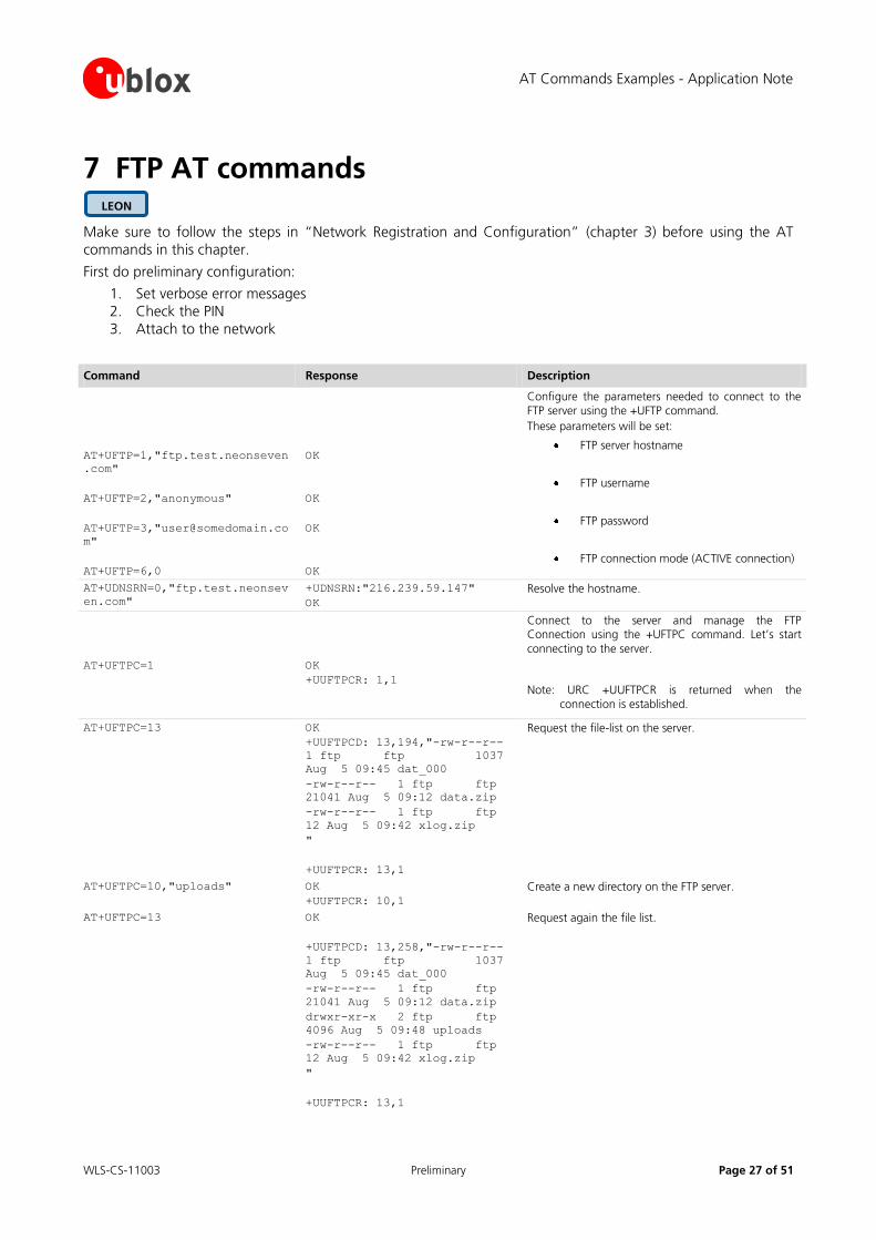
Command Response Description
AT+UFTP=1,"ftp.test.neonseven
.com"
AT+UFTP=2,"anonymous"
AT+UFTP=3,"[email protected]
m"
AT+UFTP=6,0
OK
OK
OK
OK
Configure the parameters needed to connect to the FTP server using the +UFTP command.
These parameters will be set:
FTP server hostname
FTP username
FTP password
FTP connection mode (ACTIVE connection)
AT+UDNSRN=0,"ftp.test.neonsev
en.com"
+UDNSRN:"216.239.59.147"
OK
Resolve the hostname.
Connect to the server and manage the FTP Connection using the +UFTPC command. Let’s start
connecting to the server.
AT+UFTPC=1 OK
+UUFTPCR: 1,1
Note: URC +UUFTPCR is returned when the connection is established.
AT+UFTPC=13 OK
+UUFTPCD: 13,194,"-rw-r--r--
1 ftp ftp 1037
Aug 5 09:45 dat_000
-rw-r--r-- 1 ftp ftp
21041 Aug 5 09:12 data.zip
-rw-r--r-- 1 ftp ftp
12 Aug 5 09:42 xlog.zip
"
+UUFTPCR: 13,1
Request the file-list on the server.
AT+UFTPC=10,"uploads" OK
+UUFTPCR: 10,1
Create a new directory on the FTP server.
AT+UFTPC=13 OK
+UUFTPCD: 13,258,"-rw-r--r--
1 ftp ftp 1037
Aug 5 09:45 dat_000
-rw-r--r-- 1 ftp ftp
21041 Aug 5 09:12 data.zip
drwxr-xr-x 2 ftp ftp
4096 Aug 5 09:48 uploads
-rw-r--r-- 1 ftp ftp
12 Aug 5 09:42 xlog.zip
"
+UUFTPCR: 13,1
Request again the file list.
LEON
AT Commands Examples - Application Note
WLS-CS-11003 Preliminary Page 28 of 51
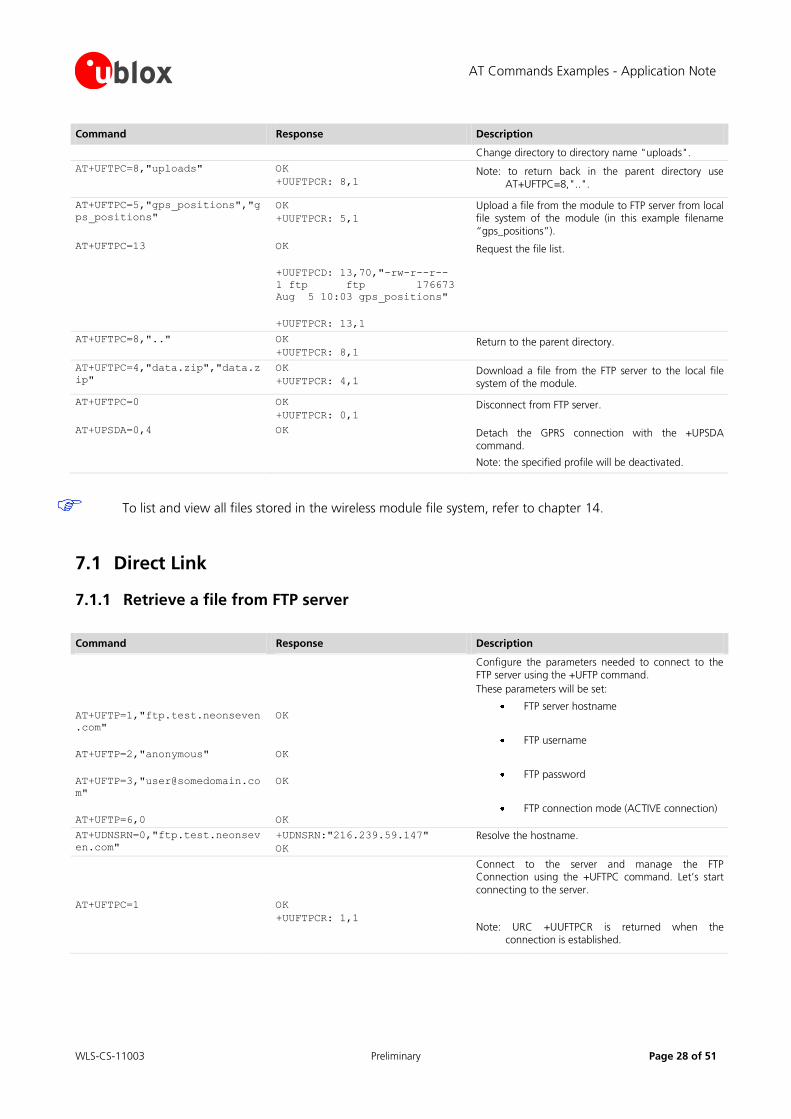
Command Response Description
Change directory to directory name "uploads".
AT+UFTPC=8,"uploads" OK
+UUFTPCR: 8,1 Note: to return back in the parent directory use
AT+UFTPC=8,"..".
AT+UFTPC=5,"gps_positions","g
ps_positions"
OK
+UUFTPCR: 5,1
Upload a file from the module to FTP server from local file system of the module (in this example filename
“gps_positions”).
AT+UFTPC=13 OK
+UUFTPCD: 13,70,"-rw-r--r--
1 ftp ftp 176673
Aug 5 10:03 gps_positions"
+UUFTPCR: 13,1
Request the file list.
AT+UFTPC=8,".." OK
+UUFTPCR: 8,1 Return to the parent directory.
AT+UFTPC=4,"data.zip","data.z
ip"
OK
+UUFTPCR: 4,1 Download a file from the FTP server to the local file system of the module.
AT+UFTPC=0 OK
+UUFTPCR: 0,1 Disconnect from FTP server.
AT+UPSDA=0,4 OK Detach the GPRS connection with the +UPSDA command.
Note: the specified profile will be deactivated.
To list and view all files stored in the wireless module file system, refer to chapter 14.
7.1 Direct Link
7.1.1 Retrieve a file from FTP server
Command Response Description
AT+UFTP=1,"ftp.test.neonseven
.com"
AT+UFTP=2,"anonymous"
AT+UFTP=3,"[email protected]
m"
AT+UFTP=6,0
OK
OK
OK
OK
Configure the parameters needed to connect to the FTP server using the +UFTP command.
These parameters will be set:
FTP server hostname
FTP username
FTP password
FTP connection mode (ACTIVE connection)
AT+UDNSRN=0,"ftp.test.neonsev
en.com"
+UDNSRN:"216.239.59.147"
OK
Resolve the hostname.
Connect to the server and manage the FTP Connection using the +UFTPC command. Let’s start
connecting to the server.
AT+UFTPC=1 OK
+UUFTPCR: 1,1
Note: URC +UUFTPCR is returned when the connection is established.

AT Commands Examples - Application Note
WLS-CS-11003 Preliminary Page 29 of 51
Command Response Description
AT+UFTPC=6,"file_to_retrieve" CONNECT Send to FTP server a RETRIEVE file request for
file_to_retrieve.
Once user gets the response CONNECT direct link mode is activated. Data received from FTP connection
will be redirected to the serial port.
+++ DISCONNECT
OK
+UUFTPCR: 6,1
WARNING: When the file has entirely been retrieved module does not exit from direct link mode. It’s necessary to exit manually using “+++” escape sequence.
URC +UUFTPCR notifies if retrieve operation has been concluded successfully.
Note: DISCONNECT message is provided on LEON-G100-04x/LEON-G200-04x and subsequent versions and LISA-U1 / LISA-H1 series
7.1.2 Aborting retrieve file request
Command Response Description
+++ DISCONNECT
OK
+UUFTPCR: 6,0
If entering “+++” escape sequence before the requested file has been entirely retrieved from FTP server, module exits from direct link and URC +UUFTPCR notifies that retrieve operation hasn’t been concluded successfully.
Note: DISCONNECT message is provided on LEON-G100-04x/LEON-G200-04x and subsequent versions and LISA-U1 / LISA-H1 series
7.1.3 Store a file on FTP server
Command Response Description
AT+UFTP=1,"ftp.test.neonseven
.com"
AT+UFTP=2,"anonymous"
AT+UFTP=3,"[email protected]
m"
AT+UFTP=6,0
OK
OK
OK
OK
Configure the parameters needed to connect to the FTP server using the +UFTP command.
These parameters will be set:
FTP server hostname
FTP username
FTP password
FTP connection mode (ACTIVE connection)
AT+UDNSRN=0,"ftp.test.neonsev
en.com"
+UDNSRN:"216.239.59.147"
OK
Resolve the hostname.
Connect to the server and manage the FTP.
Connection using the +UFTPC command. Let’s start
connecting to the server.
AT Commands Examples - Application Note
WLS-CS-11003 Preliminary Page 30 of 51
Command Response Description
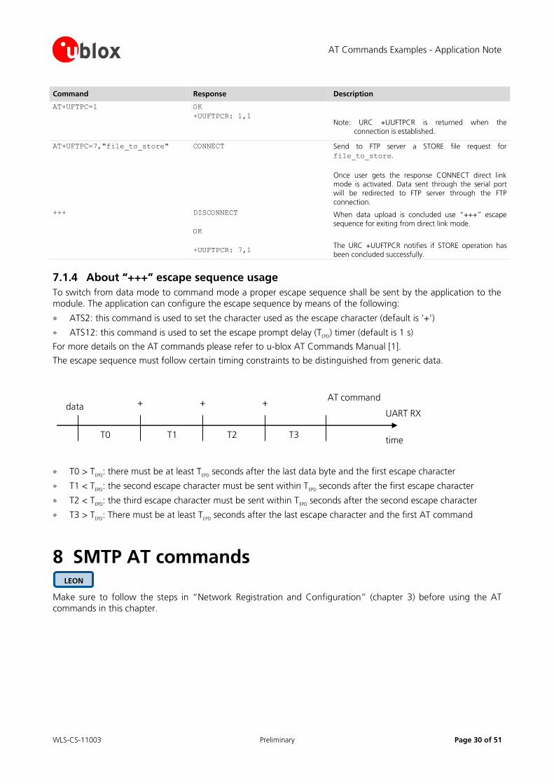
AT+UFTPC=1 OK
+UUFTPCR: 1,1
Note: URC +UUFTPCR is returned when the connection is established.
AT+UFTPC=7,"file_to_store" CONNECT Send to FTP server a STORE file request for
file_to_store.
Once user gets the response CONNECT direct link mode is activated. Data sent through the serial port will be redirected to FTP server through the FTP
connection.
+++ DISCONNECT
OK
+UUFTPCR: 7,1
When data upload is concluded use “+++” escape sequence for exiting from direct link mode.
The URC +UUFTPCR notifies if STORE operation has been concluded successfully.
7.1.4 About “+++” escape sequence usage
To switch from data mode to command mode a proper escape sequence shall be sent by the application to the
module. The application can configure the escape sequence by means of the following:
ATS2: this command is used to set the character used as the escape character (default is ‘+’)
ATS12: this command is used to set the escape prompt delay (TEPD
) timer (default is 1 s)
For more details on the AT commands please refer to u-blox AT Commands Manual [1].
The escape sequence must follow certain timing constraints to be distinguished from generic data.
T0 T1 T2 T3
data + ++AT command
UART RX
time
T0 > TEPD
: there must be at least TEPD
seconds after the last data byte and the first escape character
T1 < TEPD
: the second escape character must be sent within TEPD
seconds after the first escape character
T2 < TEPD
: the third escape character must be sent within TEPD
seconds after the second escape character
T3 > TEPD
: There must be at least TEPD
seconds after the last escape character and the first AT command
8 SMTP AT commands
Make sure to follow the steps in “Network Registration and Configuration” (chapter 3) before using the AT
commands in this chapter.
LEON
AT Commands Examples - Application Note
WLS-CS-11003 Preliminary Page 31 of 51
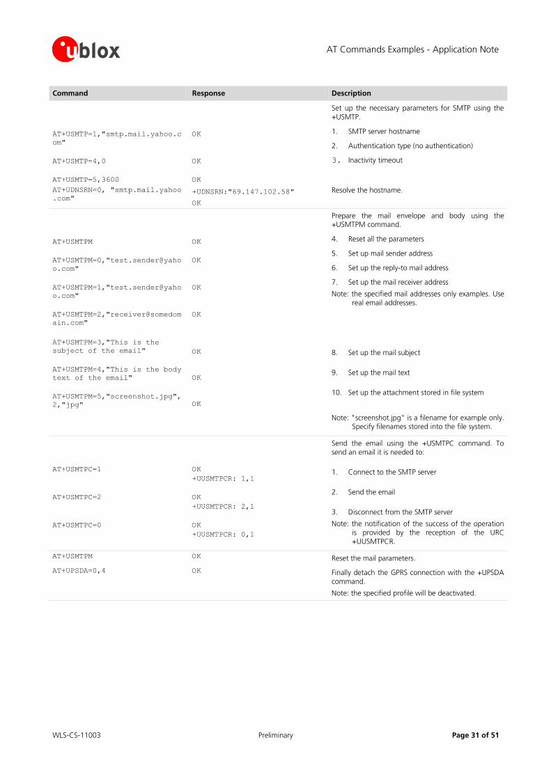
Command Response Description
AT+USMTP=1,"smtp.mail.yahoo.c
om"
AT+USMTP=4,0
AT+USMTP=5,3600
OK
OK
OK
Set up the necessary parameters for SMTP using the +USMTP.
1. SMTP server hostname
2. Authentication type (no authentication)
3. Inactivity timeout
AT+UDNSRN=0, "smtp.mail.yahoo
.com" +UDNSRN:"69.147.102.58"
OK
Resolve the hostname.
AT+USMTPM
AT+USMTPM=0,"test.sender@yaho
o.com"
AT+USMTPM=1,"test.sender@yaho
o.com"
AT+USMTPM=2,"receiver@somedom
ain.com"
OK
OK
OK
OK
Prepare the mail envelope and body using the +USMTPM command.
4. Reset all the parameters
5. Set up mail sender address
6. Set up the reply-to mail address
7. Set up the mail receiver address
Note: the specified mail addresses only examples. Use real email addresses.
AT+USMTPM=3,"This is the
subject of the email"
AT+USMTPM=4,"This is the body
text of the email"
AT+USMTPM=5,"screenshot.jpg",
2,"jpg"
OK
OK
OK
8. Set up the mail subject
9. Set up the mail text
10. Set up the attachment stored in file system
Note: "screenshot.jpg" is a filename for example only. Specify filenames stored into the file system.
AT+USMTPC=1
AT+USMTPC=2
AT+USMTPC=0
OK
+UUSMTPCR: 1,1
OK
+UUSMTPCR: 2,1
OK
+UUSMTPCR: 0,1
Send the email using the +USMTPC command. To send an email it is needed to:
1. Connect to the SMTP server
2. Send the email
3. Disconnect from the SMTP server
Note: the notification of the success of the operation is provided by the reception of the URC +UUSMTPCR.
AT+USMTPM OK Reset the mail parameters.
AT+UPSDA=0,4 OK Finally detach the GPRS connection with the +UPSDA command.
Note: the specified profile will be deactivated.
AT Commands Examples - Application Note
WLS-CS-11003 Preliminary Page 32 of 51
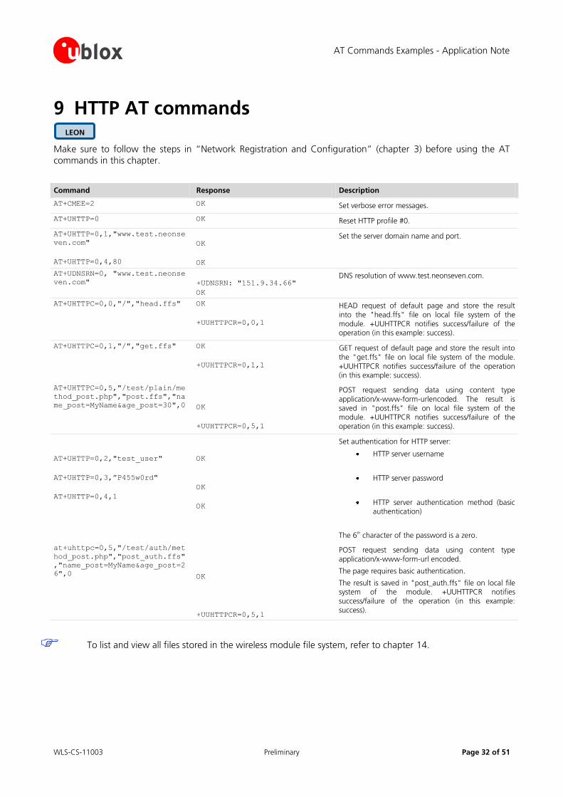
9 HTTP AT commands
Make sure to follow the steps in “Network Registration and Configuration” (chapter 3) before using the AT
commands in this chapter.
Command Response Description
AT+CMEE=2 OK Set verbose error messages.
AT+UHTTP=0 OK Reset HTTP profile #0.
AT+UHTTP=0,1,"www.test.neonse
ven.com"
AT+UHTTP=0,4,80
OK
OK
Set the server domain name and port.
AT+UDNSRN=0, "www.test.neonse
ven.com"
+UDNSRN: "151.9.34.66"
OK
DNS resolution of www.test.neonseven.com.
AT+UHTTPC=0,0,"/","head.ffs" OK
+UUHTTPCR=0,0,1
HEAD request of default page and store the result into the "head.ffs" file on local file system of the module. +UUHTTPCR notifies success/failure of the operation (in this example: success).
AT+UHTTPC=0,1,"/","get.ffs" OK
+UUHTTPCR=0,1,1
GET request of default page and store the result into the "get.ffs" file on local file system of the module. +UUHTTPCR notifies success/failure of the operation (in this example: success).
AT+UHTTPC=0,5,"/test/plain/me
thod_post.php","post.ffs","na
me_post=MyName&age_post=30",0
OK
+UUHTTPCR=0,5,1
POST request sending data using content type application/x-www-form-urlencoded. The result is saved in "post.ffs" file on local file system of the module. +UUHTTPCR notifies success/failure of the operation (in this example: success).
AT+UHTTP=0,2,"test_user"
AT+UHTTP=0,3,”P455w0rd"
AT+UHTTP=0,4,1
OK
OK
OK
Set authentication for HTTP server:
HTTP server username
HTTP server password
HTTP server authentication method (basic authentication)
The 6th character of the password is a zero.
at+uhttpc=0,5,"/test/auth/met
hod_post.php","post_auth.ffs"
,"name_post=MyName&age_post=2
6",0
OK
+UUHTTPCR=0,5,1
POST request sending data using content type application/x-www-form-url encoded.
The page requires basic authentication.
The result is saved in "post_auth.ffs" file on local file system of the module. +UUHTTPCR notifies success/failure of the operation (in this example: success).
To list and view all files stored in the wireless module file system, refer to chapter 14.
LEON
AT Commands Examples - Application Note
WLS-CS-11003 Preliminary Page 33 of 51
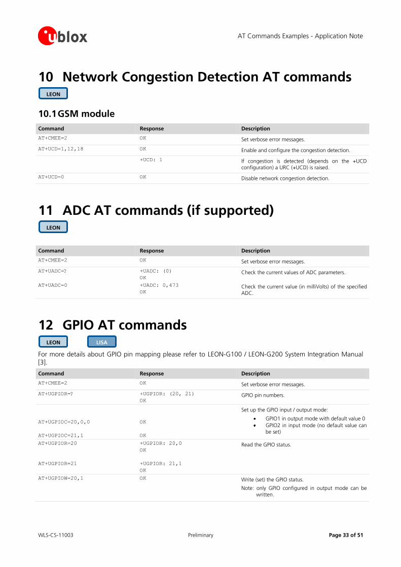
10 Network Congestion Detection AT commands
10.1 GSM module
Command Response Description
AT+CMEE=2 OK Set verbose error messages.
AT+UCD=1,12,18 OK Enable and configure the congestion detection.
+UCD: 1 If congestion is detected (depends on the +UCD configuration) a URC (+UCD) is raised.
AT+UCD=0 OK Disable network congestion detection.
11 ADC AT commands (if supported)
Command Response Description
AT+CMEE=2 OK Set verbose error messages.
AT+UADC=? +UADC: (0)
OK Check the current values of ADC parameters.
AT+UADC=0 +UADC: 0,473
OK Check the current value (in milliVolts) of the specified ADC.
12 GPIO AT commands
For more details about GPIO pin mapping please refer to LEON-G100 / LEON-G200 System Integration Manual
[3].
Command Response Description
AT+CMEE=2 OK Set verbose error messages.
AT+UGPIOR=? +UGPIOR: (20, 21)
OK GPIO pin numbers.
AT+UGPIOC=20,0,0
AT+UGPIOC=21,1
OK
OK
Set up the GPIO input / output mode:
GPIO1 in output mode with default value 0
GPIO2 in input mode (no default value can be set)
AT+UGPIOR=20
AT+UGPIOR=21
+UGPIOR: 20,0
OK
+UGPIOR: 21,1
OK
Read the GPIO status.
AT+UGPIOW=20,1 OK Write (set) the GPIO status.
Note: only GPIO configured in output mode can be written.
LISA LEON
LEON
LEON
AT Commands Examples - Application Note
WLS-CS-11003 Preliminary Page 34 of 51
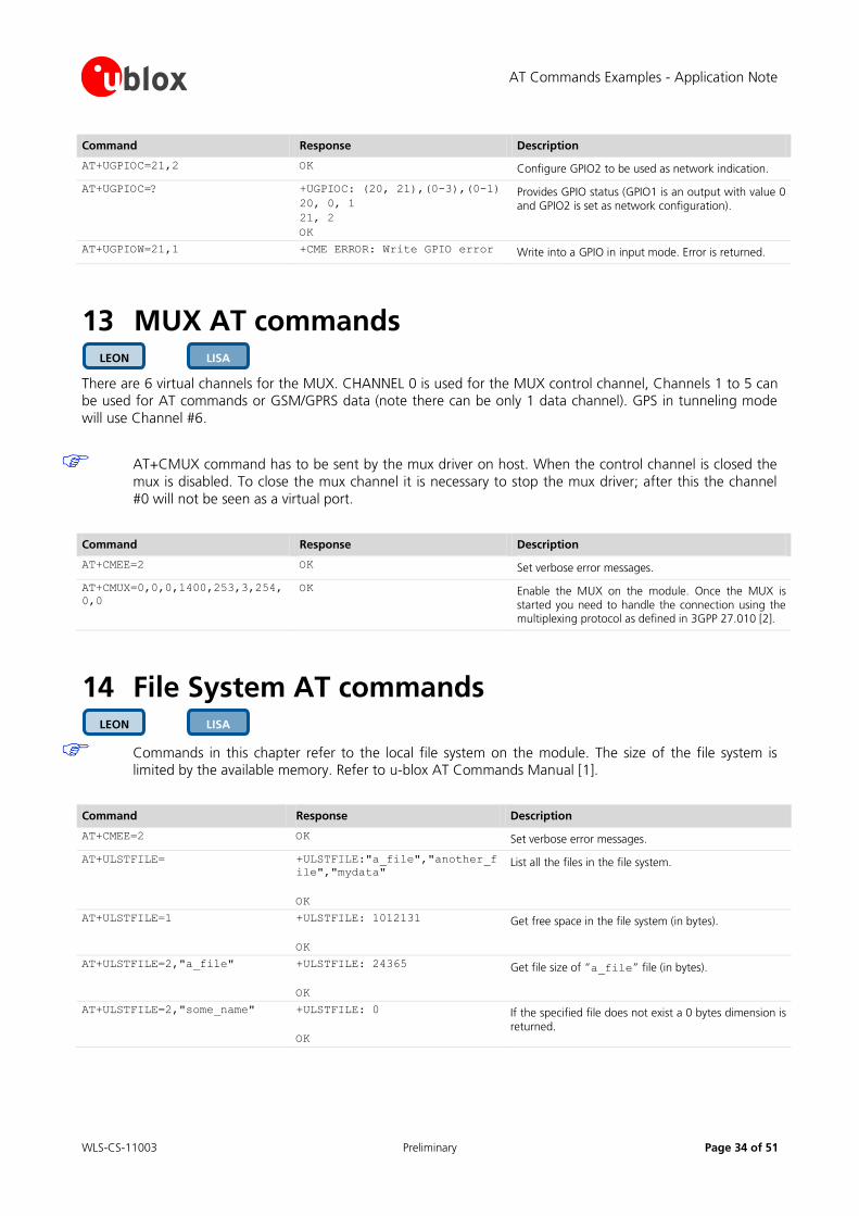
Command Response Description
AT+UGPIOC=21,2 OK Configure GPIO2 to be used as network indication.
AT+UGPIOC=? +UGPIOC: (20, 21),(0-3),(0-1)
20, 0, 1
21, 2
OK
Provides GPIO status (GPIO1 is an output with value 0 and GPIO2 is set as network configuration).
AT+UGPIOW=21,1 +CME ERROR: Write GPIO error Write into a GPIO in input mode. Error is returned.
13 MUX AT commands
There are 6 virtual channels for the MUX. CHANNEL 0 is used for the MUX control channel, Channels 1 to 5 can be used for AT commands or GSM/GPRS data (note there can be only 1 data channel). GPS in tunneling mode
will use Channel #6.
AT+CMUX command has to be sent by the mux driver on host. When the control channel is closed the
mux is disabled. To close the mux channel it is necessary to stop the mux driver; after this the channel
#0 will not be seen as a virtual port.
Command Response Description
AT+CMEE=2 OK Set verbose error messages.
AT+CMUX=0,0,0,1400,253,3,254,
0,0
OK Enable the MUX on the module. Once the MUX is started you need to handle the connection using the multiplexing protocol as defined in 3GPP 27.010 [2].
14 File System AT commands
Commands in this chapter refer to the local file system on the module. The size of the file system is limited by the available memory. Refer to u-blox AT Commands Manual [1].
Command Response Description
AT+CMEE=2 OK Set verbose error messages.
AT+ULSTFILE= +ULSTFILE:"a_file","another_f
ile","mydata"
OK
List all the files in the file system.
AT+ULSTFILE=1 +ULSTFILE: 1012131
OK
Get free space in the file system (in bytes).
AT+ULSTFILE=2,"a_file" +ULSTFILE: 24365
OK
Get file size of “a_file” file (in bytes).
AT+ULSTFILE=2,"some_name" +ULSTFILE: 0
OK
If the specified file does not exist a 0 bytes dimension is returned.
LISA LEON
LISA LEON
AT Commands Examples - Application Note
WLS-CS-11003 Preliminary Page 35 of 51
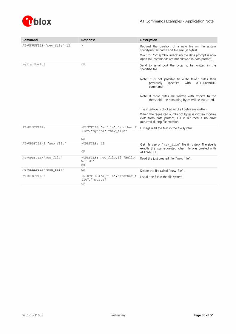
Command Response Description
AT+UDWNFILE="new_file",12 > Request the creation of a new file on file system specifying file name and file size (in bytes).
Wait for “>” symbol indicating the data prompt is now open (AT commands are not allowed in data prompt).
Hello World! OK Send to serial port the bytes to be written in the specified file.
Note: It is not possible to write fewer bytes than previously specified with AT+UDWNFILE command.
Note: If more bytes are written with respect to the threshold, the remaining bytes will be truncated.
The interface is blocked until all bytes are written.
When the requested number of bytes is written module exits from data prompt, OK is returned if no error occurred during file creation.
AT+ULSTFILE= +ULSTFILE:"a_file","another_f
ile","mydata","new_file"
OK
List again all the files in the file system.
AT+URDFILE=2,"new_file" +URDFILE: 12
OK
Get file size of “new_file” file (in bytes). The size is
exactly the size requested when file was created with +UDWNFILE.
AT+URDFILE="new_file" +URDFILE: new_file,12,"Hello
World!"
OK
Read the just created file ("new_file").
AT+UDELFILE="new_file" OK Delete the file called "new_file".
AT+ULSTFILE= +ULSTFILE:"a_file","another_f
ile","mydata"
OK
List all the file in the file system.
AT Commands Examples - Application Note
WLS-CS-11003 Preliminary Page 36 of 51
15 SIM Toolkit
SIM Application Toolkit (SAT) is a set of commands and procedures which may be used during a GSM session.
The SAT provides mechanisms which allow applications, existing in the SIM, to interact and operate with any
MT, which supports the specific mechanisms required by the application.
The specifications related to SIM toolkit are u-blox AT Commands Manual [1], 3GPP TS 27.010 [2], 3GPP TS
11.11 [4] and 3GPP TS 11.14 [5].
The SAT can be activated by sending +CFUN=6, this enables the SIM-toolkit interface and fetching of proactive commands by SIM-APPL from the SIM-card. After the activation of the SIM toolkit interface, the setup menu may
be displayed via +STKPRO URC when available from the SIM (immediately or after PIN insertion).
The commands in this section work properly only if the SIM toolkit interface has been activated by the DTE. Otherwise the SIM-toolkit processing will be blocked.
15.1 Profile download
Profile downloading provides a mechanism for the MT to tell the SIM what it is capable of, and the SIM can then
limit its instruction range accordingly. If no command is sent by the MT, the SIM shall assume that the MT does
not support SIM Application Toolkit.
The Terminal Profile can be queried by +STKPROF and the result is the list of SAT facilities that are supported by
the MT, as specified in 3GPP Technical Specification 11.14 [5].
Command Response Description
AT+CFUN=6 OK Activate the SAT (if not already enabled).
AT+STKPROF? +STKPROF:
17,"FFFFFFFF7F0300DF7F0000000
0010A0003"
OK
The reading result of the terminal profile data.
The terminal profile is sent at power up from MT to SIM, no matter if SAT is enabled or not.
15.2 Proactive SIM
A proactive SIM is a SIM which is capable of issuing commands to the MT within the T=0 protocol, which is
specified in ISO/IEC 7816-3 [6]. The MT is always the "master" and initiates commands to the SIM, and therefore there is no mechanism for the SIM to initiate a communication with the MT. This limits the possibility of
introducing new SIM features requiring the support of the MT, as the MT needs to know in advance what
actions it should take. The SIM shall execute all SAT proactive commands or procedures in such a way as not to jeopardise, or cause suspension, of service provisioning to the user.
Proactive SIM gives a mechanism whereby the SIM can initiate actions to be taken by the MT. These actions
include:
Displaying text from the SIM to the MT
Sending a short message
Setting up a voice call to a number held by the SIM
Setting up a data call to a number and bearer capabilities held by the SIM
Sending a SS control or USSD string
Playing tone in earpiece
LISA LEON

AT Commands Examples - Application Note
WLS-CS-11003 Preliminary Page 37 of 51
Initiating a dialogue with the user
SIM initialization request and notification of changes to EF(s)
Providing local information from the MT to the SIM
Communicating with the additional card(s) (if class "a" is supported)
Providing information about the additional card reader(s) (if class "a" is supported)
Managing timers running physically in the MT
Running an AT command received from the SIM, and returning the result to the SIM (if class "b" is
supported)
Sending DTMF
Requesting the MT to launch the browser corresponding to a URL (if class "c" is supported)
Establishing and managing a bearer independent protocol (if class "e" is supported)
The list of the supported proactive commands can be queried by sending +STKPRO in test command syntax.
Command Response Description
AT+CFUN=6 OK Activate the SAT (if not already enabled).
AT+STKPRO=? +STKPRO=01,05,16,17,18,19,20,
21,32,33,34,35,36,37,38,40,53
OK
Displays the list of supported proactive commands.
Referring to 3GPP TS 11.14 [5], this means that the module supports the following proactive commands:
01 (0x01) – REFRESH
05 (0x05) – SETUP EVENT LIST
16 (0x10) – SETUP CALL
17 (0x11) – SEND SS
18(0x12) – SEND USSD
19(0x13) – SEND SMS
20(0x14) – SEND DTMF
21(0x15) – LAUNCH BROWSER
32 (0x20) – PLAY TONE
33 (0x21) – DISPLAY TEXT
34 (0x22) – GET INKEY
35 (0x23) – GET INPUT
36 (0x24) – SELECT ITEM
37 (0x25) – SETUP MENU
38 (0x26) – PROVIDE LOCAL INFO
40 (0x28) – SETUP IDLE MODE TEXT
53 (0x35) – LANGUAGE NOTIFICATION
AT Commands Examples - Application Note
WLS-CS-11003 Preliminary Page 38 of 51
15.3 Example
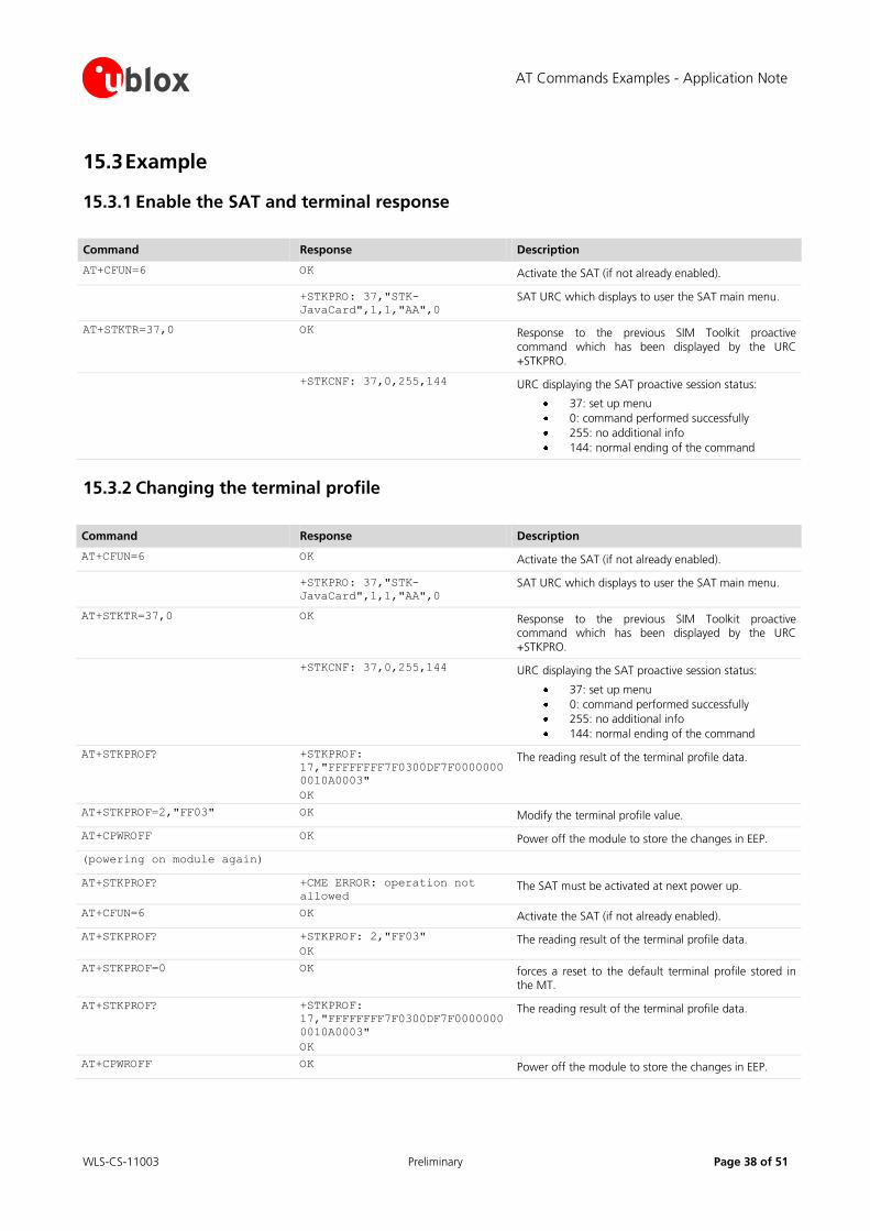
15.3.1 Enable the SAT and terminal response
Command Response Description
AT+CFUN=6 OK Activate the SAT (if not already enabled).
+STKPRO: 37,"STK-
JavaCard",1,1,"AA",0 SAT URC which displays to user the SAT main menu.
AT+STKTR=37,0 OK Response to the previous SIM Toolkit proactive command which has been displayed by the URC +STKPRO.
+STKCNF: 37,0,255,144 URC displaying the SAT proactive session status:
37: set up menu
0: command performed successfully
255: no additional info
144: normal ending of the command
15.3.2 Changing the terminal profile
Command Response Description
AT+CFUN=6 OK Activate the SAT (if not already enabled).
+STKPRO: 37,"STK-
JavaCard",1,1,"AA",0 SAT URC which displays to user the SAT main menu.
AT+STKTR=37,0 OK Response to the previous SIM Toolkit proactive command which has been displayed by the URC +STKPRO.
+STKCNF: 37,0,255,144 URC displaying the SAT proactive session status:
37: set up menu
0: command performed successfully
255: no additional info
144: normal ending of the command
AT+STKPROF? +STKPROF:
17,"FFFFFFFF7F0300DF7F0000000
0010A0003"
OK
The reading result of the terminal profile data.
AT+STKPROF=2,"FF03" OK Modify the terminal profile value.
AT+CPWROFF OK Power off the module to store the changes in EEP.
(powering on module again)
AT+STKPROF? +CME ERROR: operation not
allowed The SAT must be activated at next power up.
AT+CFUN=6 OK Activate the SAT (if not already enabled).
AT+STKPROF? +STKPROF: 2,"FF03"
OK The reading result of the terminal profile data.
AT+STKPROF=0 OK forces a reset to the default terminal profile stored in the MT.
AT+STKPROF? +STKPROF:
17,"FFFFFFFF7F0300DF7F0000000
0010A0003"
OK
The reading result of the terminal profile data.
AT+CPWROFF OK Power off the module to store the changes in EEP.
AT Commands Examples - Application Note
WLS-CS-11003 Preliminary Page 39 of 51
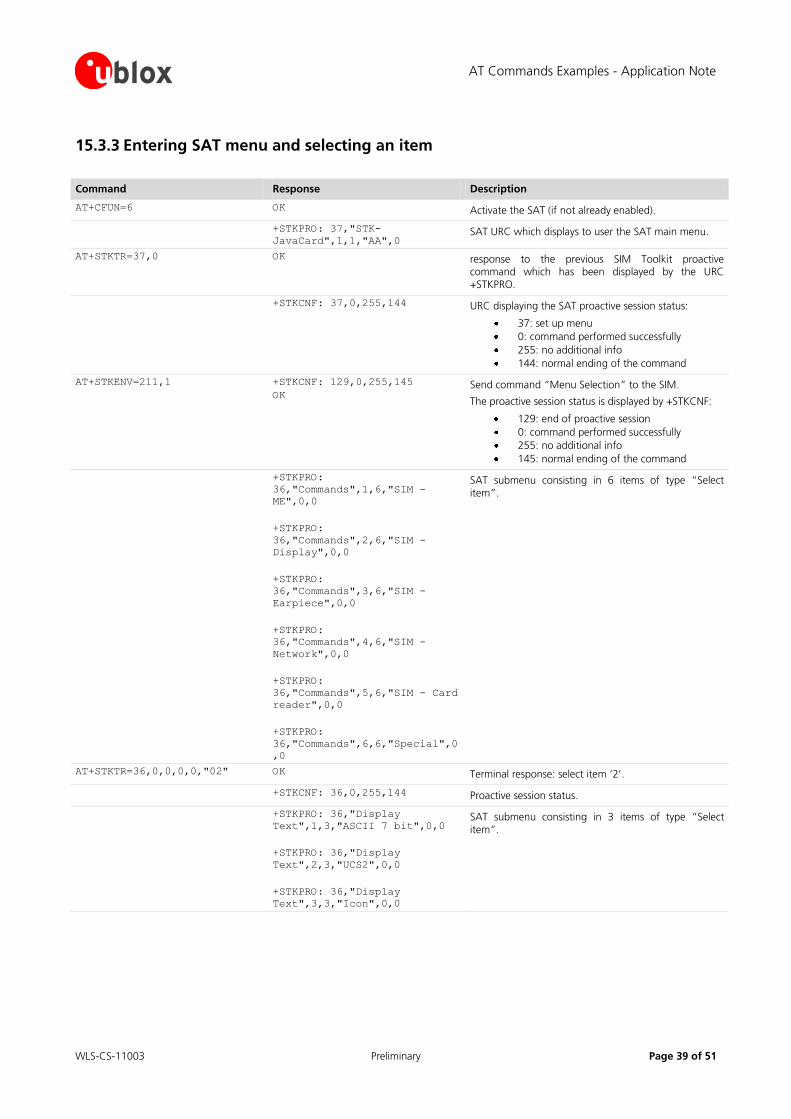
15.3.3 Entering SAT menu and selecting an item
Command Response Description
AT+CFUN=6 OK Activate the SAT (if not already enabled).
+STKPRO: 37,"STK-
JavaCard",1,1,"AA",0 SAT URC which displays to user the SAT main menu.
AT+STKTR=37,0 OK response to the previous SIM Toolkit proactive command which has been displayed by the URC +STKPRO.
+STKCNF: 37,0,255,144 URC displaying the SAT proactive session status:
37: set up menu
0: command performed successfully
255: no additional info
144: normal ending of the command
AT+STKENV=211,1 +STKCNF: 129,0,255,145
OK Send command “Menu Selection” to the SIM.
The proactive session status is displayed by +STKCNF:
129: end of proactive session
0: command performed successfully
255: no additional info
145: normal ending of the command
+STKPRO:
36,"Commands",1,6,"SIM -
ME",0,0
+STKPRO:
36,"Commands",2,6,"SIM -
Display",0,0
+STKPRO:
36,"Commands",3,6,"SIM -
Earpiece",0,0
+STKPRO:
36,"Commands",4,6,"SIM -
Network",0,0
+STKPRO:
36,"Commands",5,6,"SIM - Card
reader",0,0
+STKPRO:
36,"Commands",6,6,"Special",0
,0
SAT submenu consisting in 6 items of type “Select item”.
AT+STKTR=36,0,0,0,0,"02" OK Terminal response: select item ‘2’.
+STKCNF: 36,0,255,144 Proactive session status.
+STKPRO: 36,"Display
Text",1,3,"ASCII 7 bit",0,0
+STKPRO: 36,"Display
Text",2,3,"UCS2",0,0
+STKPRO: 36,"Display
Text",3,3,"Icon",0,0
SAT submenu consisting in 3 items of type “Select item”.
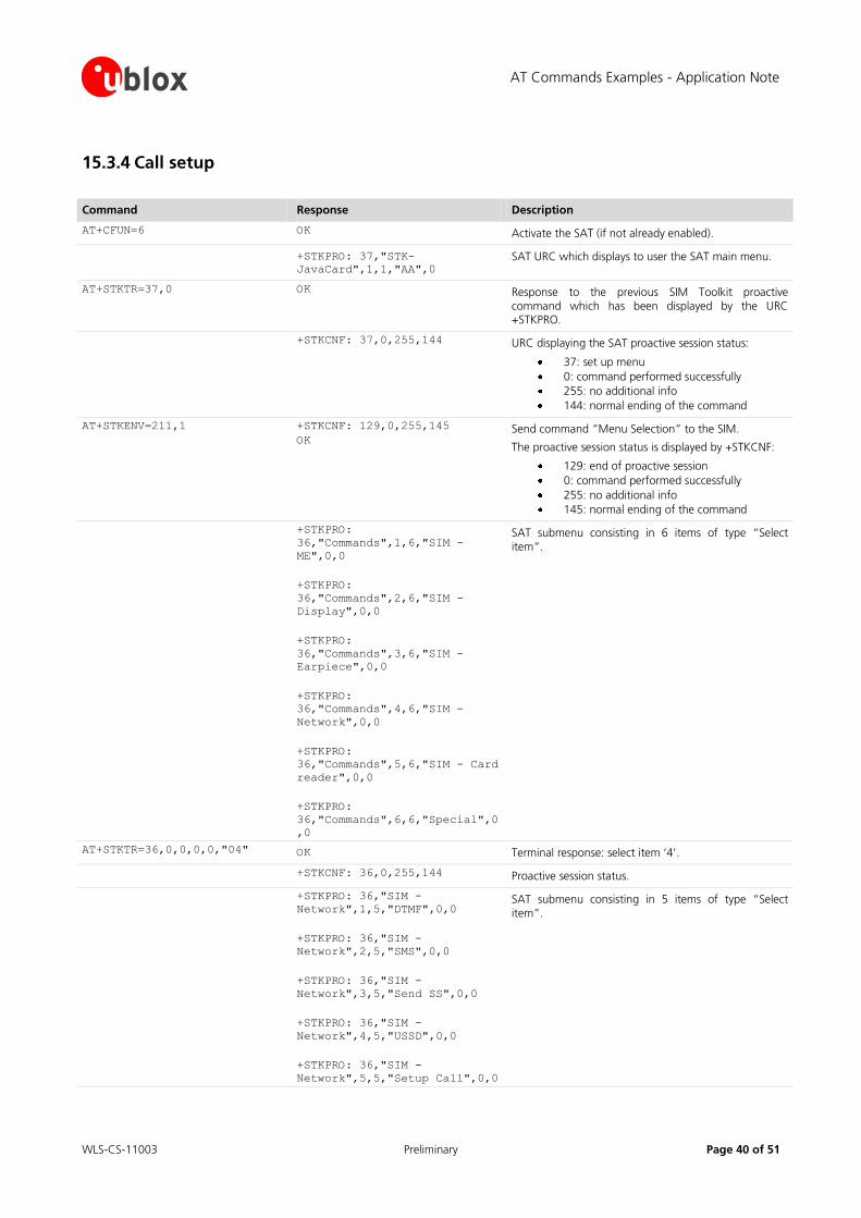
AT Commands Examples - Application Note
WLS-CS-11003 Preliminary Page 40 of 51
15.3.4 Call setup
Command Response Description
AT+CFUN=6 OK Activate the SAT (if not already enabled).
+STKPRO: 37,"STK-
JavaCard",1,1,"AA",0 SAT URC which displays to user the SAT main menu.
AT+STKTR=37,0 OK Response to the previous SIM Toolkit proactive command which has been displayed by the URC +STKPRO.
+STKCNF: 37,0,255,144 URC displaying the SAT proactive session status:
37: set up menu
0: command performed successfully
255: no additional info
144: normal ending of the command
AT+STKENV=211,1 +STKCNF: 129,0,255,145
OK Send command “Menu Selection” to the SIM.
The proactive session status is displayed by +STKCNF:
129: end of proactive session
0: command performed successfully
255: no additional info
145: normal ending of the command
+STKPRO:
36,"Commands",1,6,"SIM -
ME",0,0
+STKPRO:
36,"Commands",2,6,"SIM -
Display",0,0
+STKPRO:
36,"Commands",3,6,"SIM -
Earpiece",0,0
+STKPRO:
36,"Commands",4,6,"SIM -
Network",0,0
+STKPRO:
36,"Commands",5,6,"SIM - Card
reader",0,0
+STKPRO:
36,"Commands",6,6,"Special",0
,0
SAT submenu consisting in 6 items of type “Select item”.
AT+STKTR=36,0,0,0,0,"04" OK Terminal response: select item ‘4’.
+STKCNF: 36,0,255,144 Proactive session status.
+STKPRO: 36,"SIM -
Network",1,5,"DTMF",0,0
+STKPRO: 36,"SIM -
Network",2,5,"SMS",0,0
+STKPRO: 36,"SIM -
Network",3,5,"Send SS",0,0
+STKPRO: 36,"SIM -
Network",4,5,"USSD",0,0
+STKPRO: 36,"SIM -
Network",5,5,"Setup Call",0,0
SAT submenu consisting in 5 items of type “Select item”.
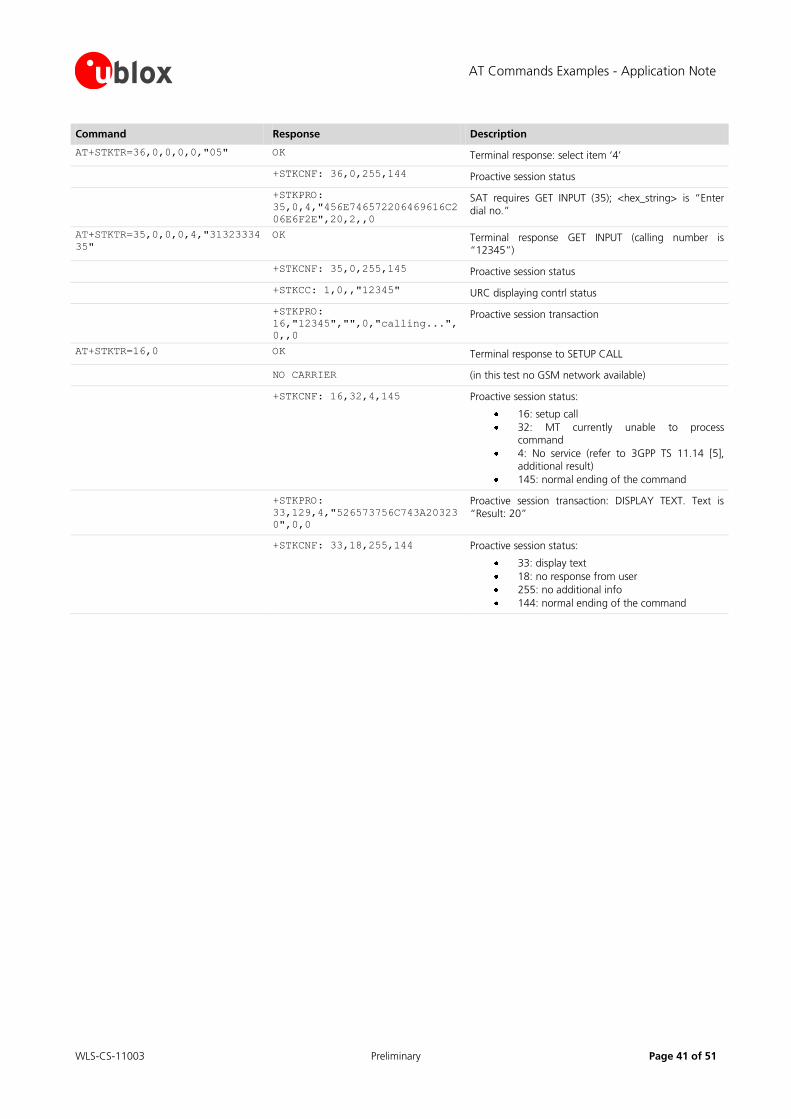
AT Commands Examples - Application Note
WLS-CS-11003 Preliminary Page 41 of 51
Command Response Description
AT+STKTR=36,0,0,0,0,"05" OK Terminal response: select item ‘4’
+STKCNF: 36,0,255,144 Proactive session status
+STKPRO:
35,0,4,"456E746572206469616C2
06E6F2E",20,2,,0
SAT requires GET INPUT (35); <hex_string> is “Enter dial no.”
AT+STKTR=35,0,0,0,4,"31323334
35"
OK Terminal response GET INPUT (calling number is “12345”)
+STKCNF: 35,0,255,145 Proactive session status
+STKCC: 1,0,,"12345" URC displaying contrl status
+STKPRO:
16,"12345","",0,"calling...",
0,,0
Proactive session transaction
AT+STKTR=16,0 OK Terminal response to SETUP CALL
NO CARRIER (in this test no GSM network available)
+STKCNF: 16,32,4,145 Proactive session status:
16: setup call
32: MT currently unable to process command
4: No service (refer to 3GPP TS 11.14 [5], additional result)
145: normal ending of the command
+STKPRO:
33,129,4,"526573756C743A20323
0",0,0
Proactive session transaction: DISPLAY TEXT. Text is “Result: 20”
+STKCNF: 33,18,255,144 Proactive session status:
33: display text
18: no response from user
255: no additional info
144: normal ending of the command
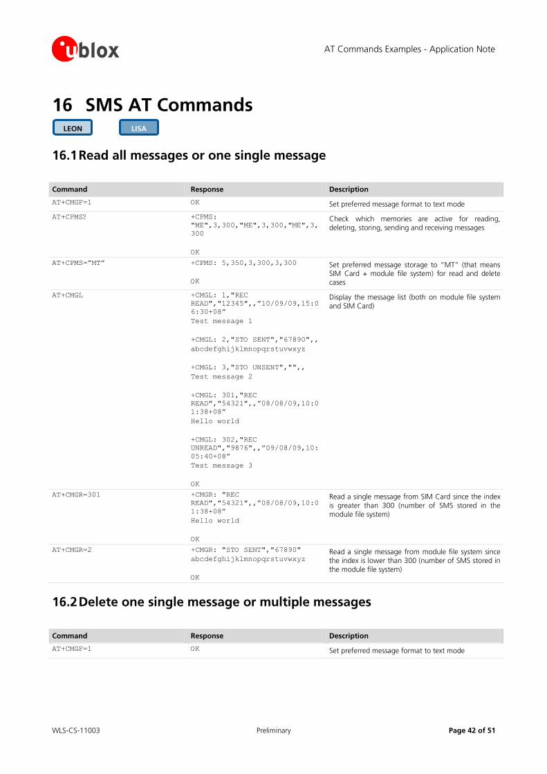
AT Commands Examples - Application Note
WLS-CS-11003 Preliminary Page 42 of 51
16 SMS AT Commands
16.1 Read all messages or one single message
Command Response Description
AT+CMGF=1 OK Set preferred message format to text mode
AT+CPMS? +CPMS:
"ME",3,300,"ME",3,300,"ME",3,
300
OK
Check which memories are active for reading, deleting, storing, sending and receiving messages
AT+CPMS=”MT” +CPMS: 5,350,3,300,3,300
OK
Set preferred message storage to “MT” (that means SIM Card + module file system) for read and delete cases
AT+CMGL +CMGL: 1,"REC
READ","12345",,”10/09/09,15:0
6:30+08”
Test message 1
+CMGL: 2,"STO SENT","67890",,
abcdefghijklmnopqrstuvwxyz
+CMGL: 3,"STO UNSENT","",,
Test message 2
+CMGL: 301,"REC
READ","54321",,”08/08/09,10:0
1:38+08”
Hello world
+CMGL: 302,"REC
UNREAD","9876",,”09/08/09,10:
05:40+08”
Test message 3
OK
Display the message list (both on module file system and SIM Card)
AT+CMGR=301 +CMGR: "REC
READ","54321",,”08/08/09,10:0
1:38+08”
Hello world
OK
Read a single message from SIM Card since the index is greater than 300 (number of SMS stored in the module file system)
AT+CMGR=2 +CMGR: "STO SENT","67890"
abcdefghijklmnopqrstuvwxyz
OK
Read a single message from module file system since the index is lower than 300 (number of SMS stored in the module file system)
16.2 Delete one single message or multiple messages
Command Response Description
AT+CMGF=1 OK Set preferred message format to text mode
LISA LEON
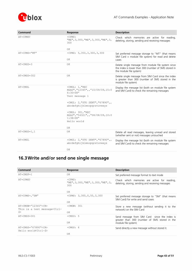
AT Commands Examples - Application Note
WLS-CS-11003 Preliminary Page 43 of 51
Command Response Description
AT+CPMS? +CPMS:
"ME",3,300,"ME",3,300,"ME",3,
300
OK
Check which memories are active for reading, deleting, storing, sending and receiving messages
AT+CPMS=”MT” +CPMS: 5,350,3,300,3,300
OK
Set preferred message storage to “MT” (that means SIM Card + module file system) for read and delete cases
AT+CMGD=3 OK Delete single message from module file system since the index is lower than 300 (number of SMS stored in the module file system)
AT+CMGD=302 OK Delete single message from SIM Card since the index is greater than 300 (number of SMS stored in the module file system)
AT+CMGL +CMGL: 1,"REC
READ","12345",,”10/09/09,15:0
6:30+08”
Test message 1
+CMGL: 2,"STO SENT","67890",,
abcdefghijklmnopqrstuvwxyz
+CMGL: 301,"REC
READ","54321",,”08/08/09,10:0
1:38+08”
Hello world
OK
Display the message list (both on module file system and SIM Card) to check the remaining messages
AT+CMGD=1,1 OK Delete all read messages, leaving unread and stored (whether sent or not) messages untouched
AT+CMGL +CMGL: 2,"STO SENT","67890",,
abcdefghijklmnopqrstuvwxyz
OK
Display the message list (both on module file system and SIM Card) to check the remaining messages
16.3 Write and/or send one single message
Command Response Description
AT+CMGF=1 OK Set preferred message format to text mode
AT+CPMS? +CPMS:
"ME",3,300,"ME",3,300,"ME",3,
300
OK
Check which memories are active for reading, deleting, storing, sending and receiving messages
AT+CPMS=,”SM” +CPMS: 3,300,0,50,3,300
OK
Set preferred message storage to “SM” (that means SIM Card) for write and send cases
AT+CMGW=”12345”<CR>
This is a test message<Ctrl-
Z>
+CMGW: 301
OK
Store a new message (without sending it to the network) on the SIM Card
AT+CMSS=301 +CMSS: 5
OK
Send message from SIM Card since the index is greater than 300 (number of SMS stored in the module file system)
AT+CMGS=”67890”<CR>
Hello world<Ctrl-Z>
+CMGS: 6
OK
Send directly a new message without stored it.
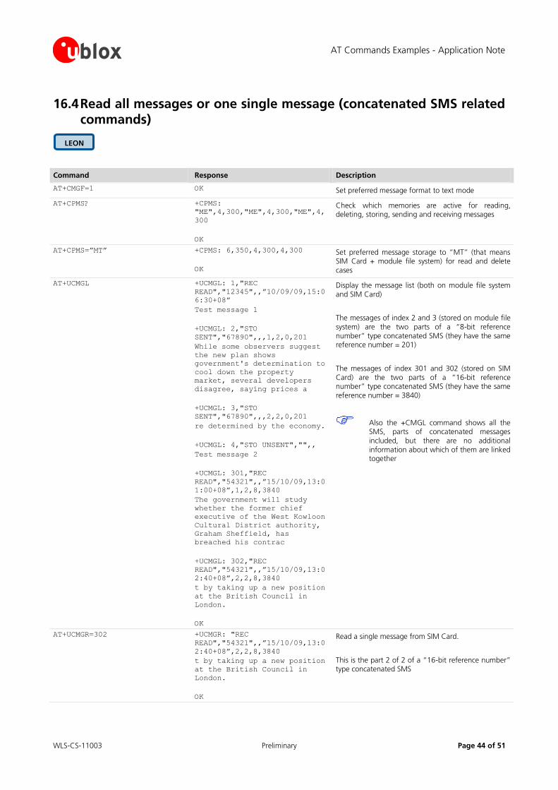
AT Commands Examples - Application Note
WLS-CS-11003 Preliminary Page 44 of 51
16.4 Read all messages or one single message (concatenated SMS related commands)
Command Response Description
AT+CMGF=1 OK Set preferred message format to text mode
AT+CPMS? +CPMS:
"ME",4,300,"ME",4,300,"ME",4,
300
OK
Check which memories are active for reading, deleting, storing, sending and receiving messages
AT+CPMS=”MT” +CPMS: 6,350,4,300,4,300
OK
Set preferred message storage to “MT” (that means SIM Card + module file system) for read and delete cases
AT+UCMGL +UCMGL: 1,"REC
READ","12345",,”10/09/09,15:0
6:30+08”
Test message 1
+UCMGL: 2,"STO
SENT","67890",,,1,2,0,201
While some observers suggest
the new plan shows
government's determination to
cool down the property
market, several developers
disagree, saying prices a
+UCMGL: 3,"STO
SENT","67890",,,2,2,0,201
re determined by the economy.
+UCMGL: 4,"STO UNSENT","",,
Test message 2
+UCMGL: 301,"REC
READ","54321",,”15/10/09,13:0
1:00+08”,1,2,8,3840
The government will study
whether the former chief
executive of the West Kowloon
Cultural District authority,
Graham Sheffield, has
breached his contrac
+UCMGL: 302,"REC
READ","54321",,”15/10/09,13:0
2:40+08”,2,2,8,3840
t by taking up a new position
at the British Council in
London.
OK
Display the message list (both on module file system and SIM Card)
The messages of index 2 and 3 (stored on module file system) are the two parts of a “8-bit reference number” type concatenated SMS (they have the same reference number = 201)
The messages of index 301 and 302 (stored on SIM Card) are the two parts of a “16-bit reference number” type concatenated SMS (they have the same reference number = 3840)
Also the +CMGL command shows all the SMS, parts of concatenated messages included, but there are no additional information about which of them are linked together
AT+UCMGR=302 +UCMGR: "REC
READ","54321",,”15/10/09,13:0
2:40+08”,2,2,8,3840
t by taking up a new position
at the British Council in
London.
OK
Read a single message from SIM Card.
This is the part 2 of 2 of a “16-bit reference number” type concatenated SMS
LEON
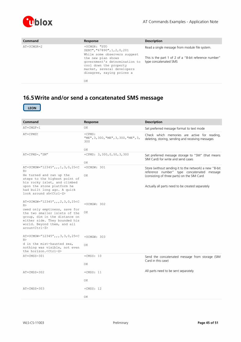
AT Commands Examples - Application Note
WLS-CS-11003 Preliminary Page 45 of 51
Command Response Description
AT+UCMGR=2 +UCMGR: "STO
SENT","67890",1,2,0,201
While some observers suggest
the new plan shows
government's determination to
cool down the property
market, several developers
disagree, saying prices a
OK
Read a single message from module file system.
This is the part 1 of 2 of a “8-bit reference number” type concatenated SMS
16.5 Write and/or send a concatenated SMS message
Command Response Description
AT+CMGF=1 OK Set preferred message format to text mode
AT+CPMS? +CPMS:
"ME",3,300,"ME",3,300,"ME",3,
300
OK
Check which memories are active for reading, deleting, storing, sending and receiving messages
AT+CPMS=,”SM” +CPMS: 3,300,0,50,3,300
OK
Set preferred message storage to “SM” (that means SIM Card) for write and send cases
AT+UCMGW=”12345”,,,1,3,0,25<C
R>
He turned and ran up the
steps to the highest point of
his rocky islet, and climbed
upon the stone platform he
had built long ago. A quick
look around sh<Ctrl-Z>
AT+UCMGW=”12345”,,,2,3,0,25<C
R>
owed only emptiness, save for
the two smaller islets of the
group, dim in the distance on
either side. They bounded his
world. Beyond them, and all
aroun<Ctrl-Z>
AT+UCMGW=”12345”,,,3,3,0,25<C
R>
d in the mist-haunted sea,
nothing was visible, not even
the horizon.<Ctrl-Z>
+UCMGW: 301
OK
+UCMGW: 302
OK
+UCMGW: 303
OK
Store (without sending it to the network) a new “8-bit reference number” type concatenated message (consisting of three parts) on the SIM Card
Actually all parts need to be created separately
AT+CMSS=301
AT+CMSS=302
AT+CMSS=303
+CMSS: 10
OK
+CMSS: 11
OK
+CMSS: 12
OK
Send the concatenated message from storage (SIM Card in this case)
All parts need to be sent separately
LEON
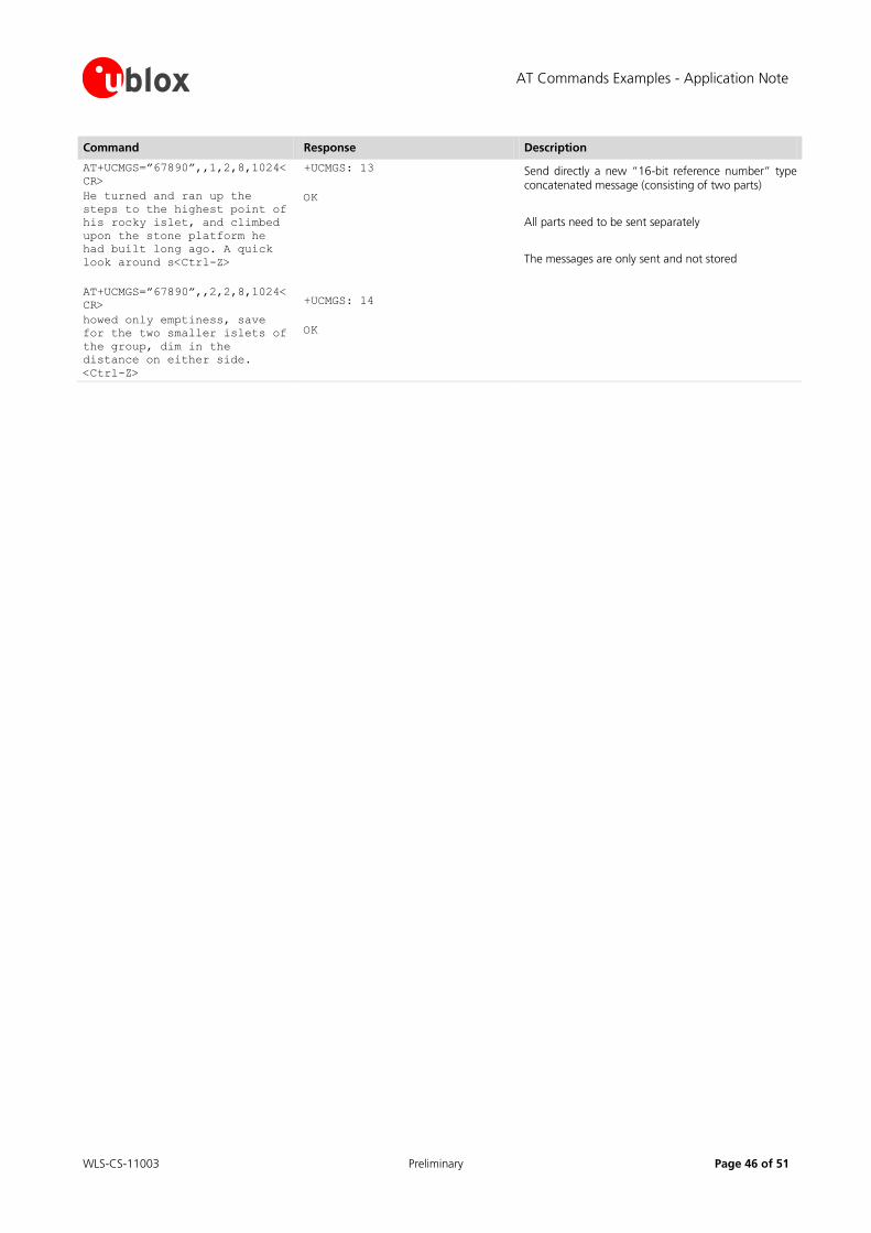
AT Commands Examples - Application Note
WLS-CS-11003 Preliminary Page 46 of 51
Command Response Description
AT+UCMGS=”67890”,,1,2,8,1024<
CR>
He turned and ran up the
steps to the highest point of
his rocky islet, and climbed
upon the stone platform he
had built long ago. A quick
look around s<Ctrl-Z>
AT+UCMGS=”67890”,,2,2,8,1024<
CR>
howed only emptiness, save
for the two smaller islets of
the group, dim in the
distance on either side.
<Ctrl-Z>
+UCMGS: 13
OK
+UCMGS: 14
OK
Send directly a new “16-bit reference number” type concatenated message (consisting of two parts)
All parts need to be sent separately
The messages are only sent and not stored
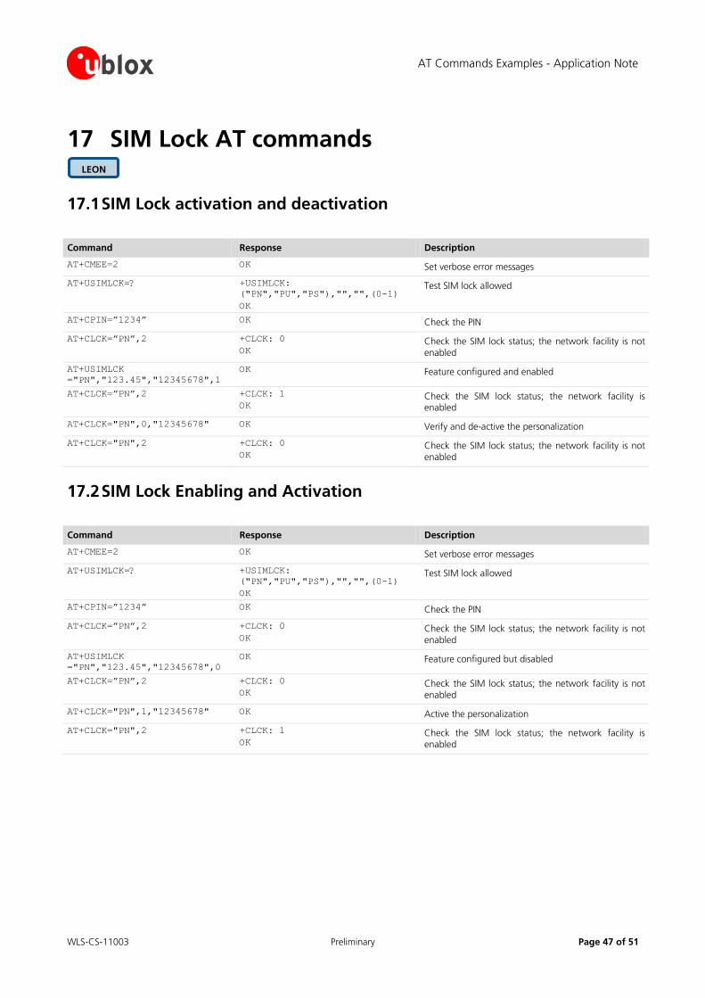
AT Commands Examples - Application Note
WLS-CS-11003 Preliminary Page 47 of 51
17 SIM Lock AT commands
17.1 SIM Lock activation and deactivation
Command Response Description
AT+CMEE=2 OK Set verbose error messages
AT+USIMLCK=? +USIMLCK:
("PN","PU","PS"),"","",(0-1)
OK
Test SIM lock allowed
AT+CPIN=”1234” OK Check the PIN
AT+CLCK=”PN”,2 +CLCK: 0
OK Check the SIM lock status; the network facility is not enabled
AT+USIMLCK
="PN","123.45","12345678",1
OK Feature configured and enabled
AT+CLCK=”PN”,2 +CLCK: 1
OK Check the SIM lock status; the network facility is enabled
AT+CLCK="PN",0,"12345678" OK Verify and de-active the personalization
AT+CLCK="PN",2 +CLCK: 0
OK Check the SIM lock status; the network facility is not enabled
17.2 SIM Lock Enabling and Activation
Command Response Description
AT+CMEE=2 OK Set verbose error messages
AT+USIMLCK=? +USIMLCK:
("PN","PU","PS"),"","",(0-1)
OK
Test SIM lock allowed
AT+CPIN=”1234” OK Check the PIN
AT+CLCK=”PN”,2 +CLCK: 0
OK Check the SIM lock status; the network facility is not enabled
AT+USIMLCK
="PN","123.45","12345678",0
OK Feature configured but disabled
AT+CLCK=”PN”,2 +CLCK: 0
OK Check the SIM lock status; the network facility is not enabled
AT+CLCK="PN",1,"12345678" OK Active the personalization
AT+CLCK="PN",2 +CLCK: 1
OK Check the SIM lock status; the network facility is enabled
LEON
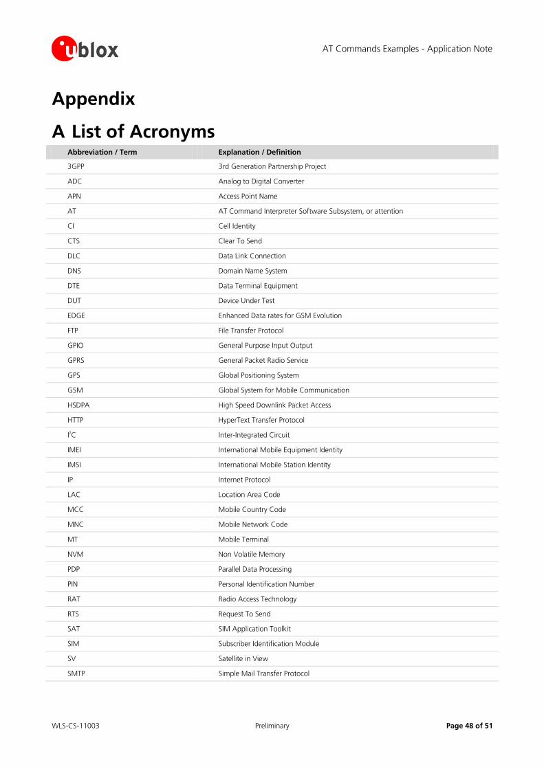
AT Commands Examples - Application Note
WLS-CS-11003 Preliminary Page 48 of 51
Appendix
A List of Acronyms Abbreviation / Term Explanation / Definition
3GPP 3rd Generation Partnership Project
ADC Analog to Digital Converter
APN Access Point Name
AT AT Command Interpreter Software Subsystem, or attention
CI Cell Identity
CTS Clear To Send
DLC Data Link Connection
DNS Domain Name System
DTE Data Terminal Equipment
DUT Device Under Test
EDGE Enhanced Data rates for GSM Evolution
FTP File Transfer Protocol
GPIO General Purpose Input Output
GPRS General Packet Radio Service
GPS Global Positioning System
GSM Global System for Mobile Communication
HSDPA High Speed Downlink Packet Access
HTTP HyperText Transfer Protocol
I2C Inter-Integrated Circuit
IMEI International Mobile Equipment Identity
IMSI International Mobile Station Identity
IP Internet Protocol
LAC Location Area Code
MCC Mobile Country Code
MNC Mobile Network Code
MT Mobile Terminal
NVM Non Volatile Memory
PDP Parallel Data Processing
PIN Personal Identification Number
RAT Radio Access Technology
RTS Request To Send
SAT SIM Application Toolkit
SIM Subscriber Identification Module
SV Satellite in View
SMTP Simple Mail Transfer Protocol
AT Commands Examples - Application Note
WLS-CS-11003 Preliminary Page 49 of 51
Abbreviation / Term Explanation / Definition
TA Timing Advance
TCP Transmission Control Protocol
TTFF Time To First Fix
UDP User Datagram Protocol
UMTS Universal Mobile Telecommunications System
URC Unsolicited Result Code
URL Uniform Resource Locator
WCDMA Wideband CODE Division Multiple Access
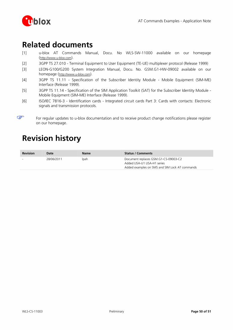
AT Commands Examples - Application Note
WLS-CS-11003 Preliminary Page 50 of 51
Related documents [1] u-blox AT Commands Manual, Docu. No WLS-SW-11000 available on our homepage
(http://www.u-blox.com).
[2] 3GPP TS 27.010 - Terminal Equipment to User Equipment (TE-UE) multiplexer protocol (Release 1999)
[3] LEON-G100/G200 System Integration Manual, Docu. No. GSM.G1-HW-09002 available on our
homepage (http://www.u-blox.com).
[4] 3GPP TS 11.11 - Specification of the Subscriber Identity Module - Mobile Equipment (SIM-ME)
Interface (Release 1999).
[5] 3GPP TS 11.14 - Specification of the SIM Application Toolkit (SAT) for the Subscriber Identity Module - Mobile Equipment (SIM-ME) Interface (Release 1999).
[6] ISO/IEC 7816-3 - Identification cards - Integrated circuit cards Part 3: Cards with contacts: Electronic
signals and transmission protocols.
For regular updates to u-blox documentation and to receive product change notifications please register
on our homepage.
Revision history
Revision Date Name Status / Comments
- 28/06/2011 lpah Document replaces GSM.G1-CS-09003-C2
Added LISA-U1 LISA-H1 series
Added examples on SMS and SIM Lock AT commands

AT Commands Examples - Application Note
WLS-CS-11003 Preliminary Page 51 of 51
Contact For complete contact information visit us at www.u-blox.com
u-blox Offices
North, Central and South America
u-blox America, Inc.
Phone: +1 (703) 483 3180
E-mail: [email protected]
Regional Office West Coast:
Phone: +1 (703) 483 3184
E-mail: [email protected]
Technical Support:
Phone: +1 (703) 483 3185
E-mail: [email protected]
Headquarters Europe, Middle East, Africa
u-blox AG
Phone: +41 44 722 74 44 E-mail: [email protected]
Support: support @u-blox.com
Asia, Australia, Pacific
u-blox Singapore Pte. Ltd.
Phone: +65 6734 3811
E-mail: [email protected] Support: [email protected]
Regional Office China:
Phone: +86 10 68 133 545 E-mail: [email protected]
Support: [email protected]
Regional Office Japan:
Phone: +81 3 5775 3850 E-mail: [email protected]
Support: [email protected]
Regional Office Korea:
Phone: +82 2 542 0861
E-mail: [email protected]
Support: [email protected]
Regional Office Taiwan:
Phone: +886 2 2657 1090
E-mail: [email protected] Support: [email protected]