at hydrohoist
TRANSCRIPT

1 Rev. 12072020
2 Rev. 12072020
At HydroHoist® we take pride in bringing the most advanced, easiest to use, and lowest maintenance boat lift sys-
tems to the market. Installation of the lift is simple due to its lightweight design and ease of operation.
The following pages contain step-by-step instructions of the installation and operation processes.
The Medium series HarborHoist™ lift takes between 10 and 20 man-hours to assemble on average depending on
the size and configuration. Review all parts, hardware, and required tools before beginning assembly. Don’t forget:
safety first.
If you have questions, contact the Technical Support Team at 1-800-825-3379.
Legend:
Requires careful consideration
WARNING: could cause harm or damage to the lift, vessel, and user
INTRODUCTION
Lifts must be installed by an approved HydroHoist® installer. Failure to comply will result in termina-
tion of warranty and could cause injury to the user and damage to the lift and vessel.
It is STRONGLY recommended that each installer read the manual before attempting an installation.

3 Rev. 12072020
PRE-INSTALLATION CONSIDERATIONS
Due to its size, the following determinations must be made before installing a HarborHoist™:
• Location of lift assembly (remote or on-site)
• Method of transport from assembly to launch site
• Equipment required to safely build, transport, and launch the lift
• Contact points between bunks and the hull (consider strakes and other hull protrusions)
If you plan to build remotely and assemble the lift before transport, first determine the lift’s minimum width from
Chart 1. State regulations may require special permits and escorts for transportation. Consider how to obtain per-
mits and the cost. Remotely building pre-sub assemblies and then completing final assembly at the launch site might
be logistically simpler.
Other items to consider:
• Does the launch site allow commercial work?
• Do you need a permit to work and/or launch at the ramp or dock?
• Is there a time limit on dock use?
• How will you transport the lift from the launch site to the install location?
• How much of the lift can be preassembled and transported safely?
• Do you have equipment with the capacity to lift subassemblies onto a trailer for transport to the launch site?
• Does the final assembly location have equipment to hoist and launch the completed lift?
• Is there level ground for final assembly, or will some assembly occur in the water?
• Verify the slip width meets the minimum requirements of the lift width, see Chart 1.
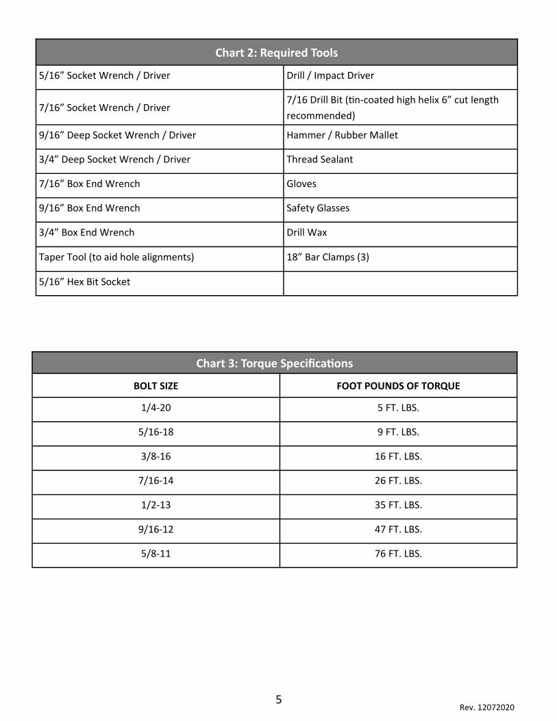
• See Chart 2 for a list of the required tools.
Working through these considerations is the first step in a successful build.

4 Rev. 12072020
Chart 1: General Specification of the Lift
*Size = Lift Capacity in lbs. per Tank
3' x 8' x 3' = 3200
4' x 8' x 3' = 5000
Main Tanks = 1100
** B = 3 x 3 V square bent beam in 100" or 104"
*** This is the minimum the lift can be for 4" of clearance per side
Standard V Hull Series *Tank Dimensions
Lifting Size Weight of lift (lbs.)
# Main Tanks
# Aux Tanks
Width Length Depth Hull Bunk
Length
Minimum Lift Width Possible
***Max Beam of Boat @ Minimum
Lift Width
Max Lift Width
8,800 Short 3600 6 1 3' 10' 2' 16' 11' 6"
8' 7" 12' 9"
12,000 4400 8 1 3' 8' 3' 20' 12' 2" 9' 4" 14'10'
12,000 Shallow 4400 8 1 3' 10' 2' 20' 12' 2" 9' 4" 14'
12,000 Wide 4500 8 1 3' 8' 3' 20' 14' 4" 11' 6" 16' 3"
15,000 4600 8 2 3' 8' 3' 20' 12' 2" 9' 4" 14'
15,000 Shallow 4600 8 2 3' 10' 2' 20' 12' 2" 9' 4" 14'
15,000 Wide 4700 8 2 3' 8' 3' 20' 14' 4" 11' 6" 16' 3"
18,000 4700 8 2 4' 8' 3' 20' 12' 6" 9' 8" 14' 5"
18,000 Narrow 4600 10 2 3' 8' 3' 28' 12' 2" 9' 4" 14'
18,000 Wide 4700 8 2 4' 8' 3' 20'
14' 4" 11' 6" 16' 3"
Lifting Size
Max Beam of Boat @
Max lift width
****Minimum Slip Recommend-
ed
**Cross Beam Used (inches)
Max Length Boat Recommended
Water Depth Req.
Overall Length of
Lift
8,800 Short 10' 34" + Vessel beam 84s 28' 31"+ Draft 16' 10"
12,000 11' 6" 34" + Vessel beam 100B 32' 43" + Draft 22' 6"
12,000 Shallow 11' 6" 34" + Vessel beam 100B 32' 31"+ Draft 22' 6"
12,000 Wide 13' 6" 34" + Vessel beam 126B 32' 43" + Draft 22' 6"
15,000 11' 6" 34" + Vessel beam 100B 34' ( 38ft performance) 43" + Draft 22' 6"
15,000 Shallow 11' 6" 34" + Vessel beam 100B 34' ( 38ft performance) 31"+ Draft 22' 6"
15,000 Wide 13' 6" 34" + Vessel beam 126B 34' ( 38ft performance) 43" + Draft 22' 6"
18,000 12' 34" + Vessel beam 104B 34' ( 38ft performance) 43" + Draft 22' 6"
18,000 Narrow 11' 6" 34" + Vessel beam 100B 40' 31"+ Draft 28' 2"
18,000 Wide 13' 6" 34" + Vessel beam 126B 34' ( 38ft performance) 43" + Draft 22' 6"
**** This assumes you are using a rope mooring solution. This measurement allows for a 4" space between the rub
rail of the vessel and walkway. If used with a pole mooring system add an additional 24" to the minimum slip width
to take into account this system. The additional 24” will allow for mooring on both sides of the lift (12” per side).
5 Rev. 12072020
Chart 3: Torque Specifications
BOLT SIZE FOOT POUNDS OF TORQUE
1/4-20 5 FT. LBS.
5/16-18 9 FT. LBS.
3/8-16 16 FT. LBS.
7/16-14 26 FT. LBS.
1/2-13 35 FT. LBS.
9/16-12 47 FT. LBS.
5/8-11 76 FT. LBS.
Chart 2: Required Tools
5/16” Socket Wrench / Driver Drill / Impact Driver
7/16” Socket Wrench / Driver 7/16 Drill Bit (tin-coated high helix 6” cut length
recommended)
9/16” Deep Socket Wrench / Driver Hammer / Rubber Mallet
3/4” Deep Socket Wrench / Driver Thread Sealant
7/16” Box End Wrench Gloves
9/16” Box End Wrench Safety Glasses
3/4” Box End Wrench Drill Wax
Taper Tool (to aid hole alignments) 18” Bar Clamps (3)
5/16” Hex Bit Socket

6 Rev. 12072020
Chart 4: PARTS LIST—8800 Short
HH-8800 V-HULL STRAIGHT BEAM SHORT FRAME
Part Description Expected Qty
TANK ASSEMBLY
HH-3000 TANK- HARBORHOIST GEN 1.5 6
HH-2650 KIT BOX, HARBORHOIST GEN 1 MOD TANK SET 3
HH-2601 TOP PLATE - HH GEN 1 MOD- ALUMINUM 6
HH-LPL-1024 GASKET - TOP HARBORHOIST 6
HH-LPL-1028 GASKET - UNDERNEATH - HARBORHOIST 12
HH-LPL-1027 GASKET - BOTTOM - HARBORHOIST 12
HH-LPL-1026 BEAM STRAP - ALUMINUM - HARBOR HOIST 12
HH-LPL-1040 CHANNEL - SUPPORT HH - ALUMINUM 12
HH-LPL-1025 STRAP PLATE - ALUMINUM HARBORHOIST 12
CROSS BEAM
HH-LPL-1018 I BEAM - 84 IN. - 8800 HH 6
WALKWAY
HH-1428 WALKWAY PANEL - HARBORHOIST G1.5 29
HH-2515 SUPPORT-WALKWAY HARBORHOIST 6
HH-LPL-1034 BEAM - 48IN SPAN - ALUM. HH. 4
HH-LPL-1033 TUBE - SPACER, 3X3 ALUMINUM 4
HH-2525 END CAP- HH WALKWAY WITH DECAL 4
HULL PADS
1035105 ASSY HYH HARBORHOIST ALUM BUNK - 16FT 2
1035195 HARDWARE KIT - HARBORHOIST HULL PADS (1 PER TANK SET) 3
CONTROL
1035233 HarborHoist Triton 5 Valve Single Blower -110 volt 1
HH-2517 CONTROL STAND HARBORHOIST GEN 1.5 1
HHE-2655 KIT, HARDWARE, CONTROL HARDWARE HH 2018 1
3072517 HOSE - RUBBER 1-1/4 in. ID X 100 ft. - CUT 1
HH-2687 KIT, HARDWARE HOSE CLAMPS AND TEES, 6600 1
AUXILLARY (AUX) TANKS
HHE-7122 I-BEAM - SINGLE AUX TANK MOUNT HH 2
HHE-7112 KIT - HARDWARE - SINGLE AUXILARY TANK HARBORHOIST 1
HHE-7117 KIT - HARDWARE - SINGLE AUXILARY TANK FITTINGS 1
HH-3350 AUXILARY TANK ASSY WITH FITTING - HARBORHOIST 36X120X24 FLAT TOP 1

7 Rev. 12072020
Chart 4: PARTS LIST—12000
HH-12000 V-HULL V-FRAME
Part Description Expected Qty
TANK ASSEMBLY
HH-3000 TANK- HARBORHOIST GEN 1.5 8
HH-2650 KIT BOX, HARBORHOIST GEN 1 MOD TANK SET 4
HH-2601 TOP PLATE - HH GEN 1 MOD- ALUMINUM 8
HH-LPL-1024 GASKET - TOP HARBORHOIST 8
HH-LPL-1028 GASKET - UNDERNEATH - HARBORHOIST 16
HH-LPL-1027 GASKET - BOTTOM - HARBORHOIST 16
HH-LPL-1026 BEAM STRAP - ALUMINUM - HARBOR HOIST 16
HH-LPL-1040 CHANNEL - SUPPORT HH - ALUMINUM 16
HH-LPL-1025 STRAP PLATE - ALUMINUM HARBORHOIST 16
CROSS BEAMS
HH-4310 CROSS CHANNEL - 3IN SQ. 100IN. V CENTER 8
WALKWAYS
HH-1428 WALKWAY PANEL - HARBORHOIST G1.5 39
HH-2515 SUPPORT-WALKWAY HARBORHOIST 8
HH-LPL-1034 BEAM - 48IN SPAN - ALUM. HH. 6
HH-LPL-1033 TUBE - SPACER, 3X3 ALUMINUM 4
HH-2525 END CAP- HH WALKWAY WITH DECAL 4
HULL PADS
1035066 ASSY HYH HARBORHOIST ALUM BUNK LEFT 22FT 1
1035067 ASSY HYH HARBORHOIST ALUM BUNK RIGHT 22FT 1
1035195 HARDWARE KIT - HARBORHOIST HULL PADS (1 PER TANK SET) 4
CONTROLS
1035233 HarborHoist Triton 5 Valve Single Blower -110 volt 1
HH-2517 CONTROL STAND HARBORHOIST GEN 1.5 1
HHE-2655 KIT, HARDWARE, CONTROL HARDWARE HH 2018 1
3072517 HOSE - RUBBER 1-1/4 in. ID X 100 ft. - CUT 1
3072512 HOSE - RUBBER 1-1/4 in. ID X 30 ft. - CUT 1
HH-2685 KIT, HARDWARE HOSE CLAMPS AND TEES, 8800 1
AUXILLARY (AUX) TANKS
HHE-7122 I-BEAM - SINGLE AUX TANK MOUNT HH 2
1033229A KIT - HARDWARE - SINGLE AUXILARY TANK HARBORHOIST 1
HHE-7117 KIT - HARDWARE - SINGLE AUXILARY TANK FITTINGS 1
HH-3730 AUXILARY TANK ASSY - HARBORHOIST 36X96X36 1

8 Rev. 12072020
Chart 4: PARTS LIST—12000 Shallow
HH-12000 V-HULL SHALLOW V-FRAME
Part Description Expected Qty
TANK ASSEMBLY
HH-3000 TANK- HARBORHOIST GEN 1.5 8
HH-2650 KIT BOX, HARBORHOIST GEN 1 MOD TANK SET 4
HH-2601 TOP PLATE - HH GEN 1 MOD- ALUMINUM 8
HH-LPL-1024 GASKET - TOP HARBORHOIST 8
HH-LPL-1028 GASKET - UNDERNEATH - HARBORHOIST 16
HH-LPL-1027 GASKET - BOTTOM - HARBORHOIST 16
HH-LPL-1026 BEAM STRAP - ALUMINUM - HARBOR HOIST 16
HH-LPL-1040 CHANNEL - SUPPORT HH - ALUMINUM 16
HH-LPL-1025 STRAP PLATE - ALUMINUM HARBORHOIST 16
CROSS BEAM
HH-4310 CROSS CHANNEL - 3IN SQ. 100IN. V CENTER 8
WALKWAY
HH-1428 WALKWAY PANEL - HARBORHOIST G1.5 39
HH-2515 SUPPORT-WALKWAY HARBORHOIST 8
HH-LPL-1034 BEAM - 48IN SPAN - ALUM. HH. 6
HH-LPL-1033 TUBE - SPACER, 3X3 ALUMINUM 4
HH-2525 END CAP- HH WALKWAY WITH DECAL 4
HULL PADS
1035066 ASSY HYH HARBORHOIST ALUM BUNK LEFT 22 FT 1
1035067 ASSY HYH HARBORHOIST ALUM BUNK RIGHT 22 FT 1
1035195 HARDWARE KIT - HARBORHOIST HULL PADS (1 PER TANK SET) 4
CONTROL
1035233 HarborHoist Triton 5 Valve Single Blower -110 volt 1
HH-2517 CONTROL STAND HARBORHOIST GEN 1.5 1
HHE-2655 KIT, HARDWARE, CONTROL HARDWARE HH 2018 1
3072517 HOSE - RUBBER 1-1/4 in. ID X 100 ft. - CUT 1
3072512 HOSE - RUBBER 1-1/4 in. ID X 30 ft. - CUT 1
HH-2685 KIT, HARDWARE HOSE CLAMPS AND TEES, 8800 1
AUXILLARY (AUX) TANKS
HHE-7122 I-BEAM - SINGLE AUX TANK MOUNT HH 2
1033229A KIT - HARDWARE - SINGLE AUXILARY TANK HARBORHOIST 1
HHE-7117 KIT - HARDWARE - SINGLE AUXILARY TANK FITTINGS 1
1034895 TANK - AUXILIARY WITH FITTING HARBORHOIST 48X120X24 FLAT TOP 1
9 Rev. 12072020
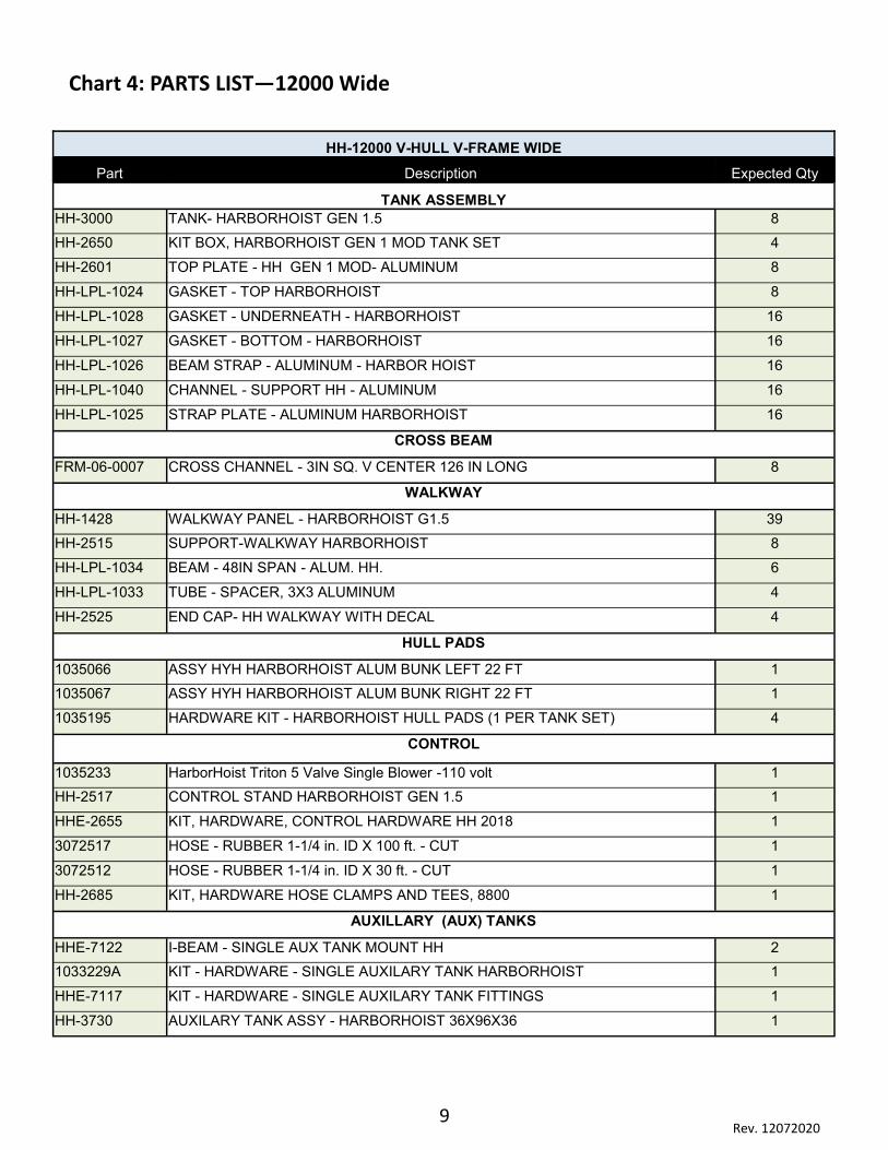
Chart 4: PARTS LIST—12000 Wide
HH-12000 V-HULL V-FRAME WIDE
Part Description Expected Qty
TANK ASSEMBLY
HH-3000 TANK- HARBORHOIST GEN 1.5 8
HH-2650 KIT BOX, HARBORHOIST GEN 1 MOD TANK SET 4
HH-2601 TOP PLATE - HH GEN 1 MOD- ALUMINUM 8
HH-LPL-1024 GASKET - TOP HARBORHOIST 8
HH-LPL-1028 GASKET - UNDERNEATH - HARBORHOIST 16
HH-LPL-1027 GASKET - BOTTOM - HARBORHOIST 16
HH-LPL-1026 BEAM STRAP - ALUMINUM - HARBOR HOIST 16
HH-LPL-1040 CHANNEL - SUPPORT HH - ALUMINUM 16
HH-LPL-1025 STRAP PLATE - ALUMINUM HARBORHOIST 16
CROSS BEAM
FRM-06-0007 CROSS CHANNEL - 3IN SQ. V CENTER 126 IN LONG 8
WALKWAY
HH-1428 WALKWAY PANEL - HARBORHOIST G1.5 39
HH-2515 SUPPORT-WALKWAY HARBORHOIST 8
HH-LPL-1034 BEAM - 48IN SPAN - ALUM. HH. 6
HH-LPL-1033 TUBE - SPACER, 3X3 ALUMINUM 4
HH-2525 END CAP- HH WALKWAY WITH DECAL 4
HULL PADS
1035066 ASSY HYH HARBORHOIST ALUM BUNK LEFT 22 FT 1
1035067 ASSY HYH HARBORHOIST ALUM BUNK RIGHT 22 FT 1
1035195 HARDWARE KIT - HARBORHOIST HULL PADS (1 PER TANK SET) 4
CONTROL
1035233 HarborHoist Triton 5 Valve Single Blower -110 volt 1
HH-2517 CONTROL STAND HARBORHOIST GEN 1.5 1
HHE-2655 KIT, HARDWARE, CONTROL HARDWARE HH 2018 1
3072517 HOSE - RUBBER 1-1/4 in. ID X 100 ft. - CUT 1
3072512 HOSE - RUBBER 1-1/4 in. ID X 30 ft. - CUT 1
HH-2685 KIT, HARDWARE HOSE CLAMPS AND TEES, 8800 1
AUXILLARY (AUX) TANKS
HHE-7122 I-BEAM - SINGLE AUX TANK MOUNT HH 2
1033229A KIT - HARDWARE - SINGLE AUXILARY TANK HARBORHOIST 1
HHE-7117 KIT - HARDWARE - SINGLE AUXILARY TANK FITTINGS 1
HH-3730 AUXILARY TANK ASSY - HARBORHOIST 36X96X36 1

10 Rev. 12072020
Chart 4: PARTS LIST—15000
HH-15000 V-HULL V-FRAME
Part Description Expected Qty
TANKS ASSEMBLY
HH-3000 TANK- HARBORHOIST GEN 1.5 8
HH-2650 KIT BOX, HARBORHOIST GEN 1 MOD TANK SET 4
HH-2601 TOP PLATE - HH GEN 1 MOD- ALUMINUM 8
HH-LPL-1024 GASKET - TOP HARBORHOIST 8
HH-LPL-1028 GASKET - UNDERNEATH - HARBORHOIST 16
HH-LPL-1027 GASKET - BOTTOM - HARBORHOIST 16
HH-LPL-1026 BEAM STRAP - ALUMINUM - HARBOR HOIST 16
HH-LPL-1040 CHANNEL - SUPPORT HH - ALUMINUM 16
HH-LPL-1025 STRAP PLATE - ALUMINUM HARBORHOIST 16
CROSS BEAM
HH-4310 CROSS CHANNEL - 3IN SQ. 100IN. V CENTER 8
WALKWAY
HH-1428 WALKWAY PANEL - HARBORHOIST G1.5 39
HH-2515 SUPPORT-WALKWAY HARBORHOIST 8
HH-LPL-1034 BEAM - 48IN SPAN - ALUM. HH. 6
HH-LPL-1033 TUBE - SPACER, 3X3 ALUMINUM 4
HH-2525 END CAP- HH WALKWAY WITH DECAL 4
HULL PADS
1035066 ASSY HYH HARBORHOIST ALUM BUNK LEFT 22 FT 1
1035067 ASSY HYH HARBORHOIST ALUM BUNK RIGHT 22 FT 1
1035195 HARDWARE KIT - HARBORHOIST HULL PADS (1 PER TANK SET) 4
CONTROL
1035233 HarborHoist Triton 5 Valve Single Blower -110 volt 1
HH-2517 CONTROL STAND HARBORHOIST GEN 1.5 1
HHE-2655 KIT, HARDWARE, CONTROL HARDWARE HH 2018 1
3072517 HOSE - RUBBER 1-1/4 in. ID X 100 ft. - CUT 1
3072512 HOSE - RUBBER 1-1/4 in. ID X 30 ft. - CUT 1
HH-2685 KIT, HARDWARE HOSE CLAMPS AND TEES, 8800 1
AUXILLARY (AUX) TANKS
HHE-7123 I-BEAM - DUAL AUX TANK MOUNT HH 2
1033229A KIT - HARDWARE - SINGLE AUXILARY TANK HARBORHOIST 2
HHE-7116 KIT - HARDWARE - DOUBLE AUXILARY TANKS 1
HH-3730 AUXILARY TANK ASSY - HARBORHOIST 36X96X36 2
11 Rev. 12072020
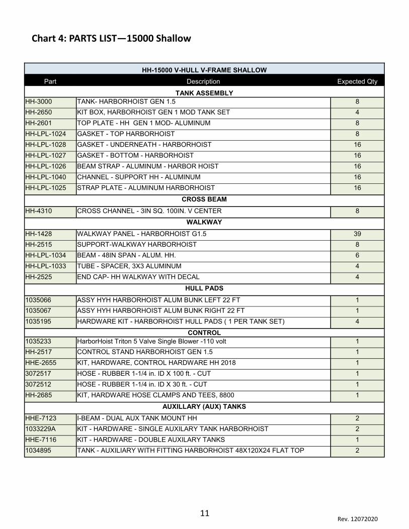
Chart 4: PARTS LIST—15000 Shallow
HH-15000 V-HULL V-FRAME SHALLOW
Part Description Expected Qty
TANK ASSEMBLY
HH-3000 TANK- HARBORHOIST GEN 1.5 8
HH-2650 KIT BOX, HARBORHOIST GEN 1 MOD TANK SET 4
HH-2601 TOP PLATE - HH GEN 1 MOD- ALUMINUM 8
HH-LPL-1024 GASKET - TOP HARBORHOIST 8
HH-LPL-1028 GASKET - UNDERNEATH - HARBORHOIST 16
HH-LPL-1027 GASKET - BOTTOM - HARBORHOIST 16
HH-LPL-1026 BEAM STRAP - ALUMINUM - HARBOR HOIST 16
HH-LPL-1040 CHANNEL - SUPPORT HH - ALUMINUM 16
HH-LPL-1025 STRAP PLATE - ALUMINUM HARBORHOIST 16
CROSS BEAM
HH-4310 CROSS CHANNEL - 3IN SQ. 100IN. V CENTER 8
WALKWAY
HH-1428 WALKWAY PANEL - HARBORHOIST G1.5 39
HH-2515 SUPPORT-WALKWAY HARBORHOIST 8
HH-LPL-1034 BEAM - 48IN SPAN - ALUM. HH. 6
HH-LPL-1033 TUBE - SPACER, 3X3 ALUMINUM 4
HH-2525 END CAP- HH WALKWAY WITH DECAL 4
HULL PADS
1035066 ASSY HYH HARBORHOIST ALUM BUNK LEFT 22 FT 1
1035067 ASSY HYH HARBORHOIST ALUM BUNK RIGHT 22 FT 1
1035195 HARDWARE KIT - HARBORHOIST HULL PADS ( 1 PER TANK SET) 4
CONTROL
1035233 HarborHoist Triton 5 Valve Single Blower -110 volt 1
HH-2517 CONTROL STAND HARBORHOIST GEN 1.5 1
HHE-2655 KIT, HARDWARE, CONTROL HARDWARE HH 2018 1
3072517 HOSE - RUBBER 1-1/4 in. ID X 100 ft. - CUT 1
3072512 HOSE - RUBBER 1-1/4 in. ID X 30 ft. - CUT 1
HH-2685 KIT, HARDWARE HOSE CLAMPS AND TEES, 8800 1
AUXILLARY (AUX) TANKS
HHE-7123 I-BEAM - DUAL AUX TANK MOUNT HH 2
1033229A KIT - HARDWARE - SINGLE AUXILARY TANK HARBORHOIST 2
HHE-7116 KIT - HARDWARE - DOUBLE AUXILARY TANKS 1
1034895 TANK - AUXILIARY WITH FITTING HARBORHOIST 48X120X24 FLAT TOP 2
12 Rev. 12072020
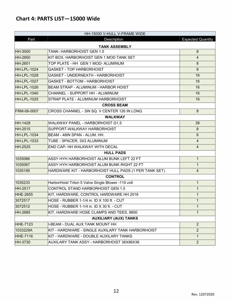
Chart 4: PARTS LIST—15000 Wide
HH-15000 V-HULL V-FRAME WIDE
Part Description Expected Quantity
TANK ASSEMBLY
HH-3000 TANK- HARBORHOIST GEN 1.5 8
HH-2650 KIT BOX, HARBORHOIST GEN 1 MOD TANK SET 4
HH-2601 TOP PLATE - HH GEN 1 MOD- ALUMINUM 8
HH-LPL-1024 GASKET - TOP HARBORHOIST 8
HH-LPL-1028 GASKET - UNDERNEATH - HARBORHOIST 16
HH-LPL-1027 GASKET - BOTTOM - HARBORHOIST 16
HH-LPL-1026 BEAM STRAP - ALUMINUM - HARBOR HOIST 16
HH-LPL-1040 CHANNEL - SUPPORT HH - ALUMINUM 16
HH-LPL-1025 STRAP PLATE - ALUMINUM HARBORHOIST 16
CROSS BEAM
FRM-06-0007 CROSS CHANNEL - 3IN SQ. V CENTER 126 IN LONG 8
WALKWAY
HH-1428 WALKWAY PANEL - HARBORHOIST G1.5 39
HH-2515 SUPPORT-WALKWAY HARBORHOIST 8
HH-LPL-1034 BEAM - 48IN SPAN - ALUM. HH. 6
HH-LPL-1033 TUBE - SPACER, 3X3 ALUMINUM 4
HH-2525 END CAP- HH WALKWAY WITH DECAL 4
HULL PADS
1035066 ASSY HYH HARBORHOIST ALUM BUNK LEFT 22 FT 1
1035067 ASSY HYH HARBORHOIST ALUM BUNK RIGHT 22 FT 1
1035195 HARDWARE KIT - HARBORHOIST HULL PADS (1 PER TANK SET) 4
CONTROL
1035233 HarborHoist Triton 5 Valve Single Blower -110 volt 1
HH-2517 CONTROL STAND HARBORHOIST GEN 1.5 1
HHE-2655 KIT, HARDWARE, CONTROL HARDWARE HH 2018 1
3072517 HOSE - RUBBER 1-1/4 in. ID X 100 ft. - CUT 1
3072512 HOSE - RUBBER 1-1/4 in. ID X 30 ft. - CUT 1
HH-2685 KIT, HARDWARE HOSE CLAMPS AND TEES, 8800 1
AUXILIARY (AUX) TANKS
HHE-7123 I-BEAM - DUAL AUX TANK MOUNT HH 2
1033229A KIT - HARDWARE - SINGLE AUXILARY TANK HARBORHOIST 2
HHE-7116 KIT - HARDWARE - DOUBLE AUXILARY TANKS 1
HH-3730 AUXILARY TANK ASSY - HARBORHOIST 36X96X36 2
13 Rev. 12072020
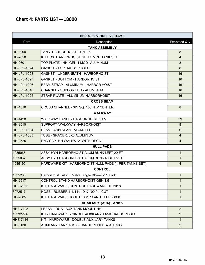
Chart 4: PARTS LIST—18000
HH-18000 V-HULL V-FRAME
Part Description Expected Qty
TANK ASSEMBLY
HH-3000 TANK- HARBORHOIST GEN 1.5 8
HH-2650 KIT BOX, HARBORHOIST GEN 1 MOD TANK SET 4
HH-2601 TOP PLATE - HH GEN 1 MOD- ALUMINUM 8
HH-LPL-1024 GASKET - TOP HARBORHOIST 8
HH-LPL-1028 GASKET - UNDERNEATH - HARBORHOIST 16
HH-LPL-1027 GASKET - BOTTOM - HARBORHOIST 16
HH-LPL-1026 BEAM STRAP - ALUMINUM - HARBOR HOIST 16
HH-LPL-1040 CHANNEL - SUPPORT HH - ALUMINUM 16
HH-LPL-1025 STRAP PLATE - ALUMINUM HARBORHOIST 16
CROSS BEAM
HH-4310 CROSS CHANNEL - 3IN SQ. 100IN. V CENTER 8
WALKWAY
HH-1428 WALKWAY PANEL - HARBORHOIST G1.5 39
HH-2515 SUPPORT-WALKWAY HARBORHOIST 8
HH-LPL-1034 BEAM - 48IN SPAN - ALUM. HH. 6
HH-LPL-1033 TUBE - SPACER, 3X3 ALUMINUM 4
HH-2525 END CAP- HH WALKWAY WITH DECAL 4
HULL PADS
1035066 ASSY HYH HARBORHOIST ALUM BUNK LEFT 22 FT 1
1035067 ASSY HYH HARBORHOIST ALUM BUNK RIGHT 22 FT 1
1035195 HARDWARE KIT - HARBORHOIST HULL PADS (1 PER TANKS SET) 4
CONTROL
1035233 HarborHoist Triton 5 Valve Single Blower -110 volt 1
HH-2517 CONTROL STAND HARBORHOIST GEN 1.5 1
HHE-2655 KIT, HARDWARE, CONTROL HARDWARE HH 2018 1
3072517 HOSE - RUBBER 1-1/4 in. ID X 100 ft. - CUT 1
HH-2685 KIT, HARDWARE HOSE CLAMPS AND TEES, 8800 1
AUXILIARY (AUX) TANKS
HHE-7123 I-BEAM - DUAL AUX TANK MOUNT HH 2
1033229A KIT - HARDWARE - SINGLE AUXILARY TANK HARBORHOIST 2
HHE-7116 KIT - HARDWARE - DOUBLE AUXILARY TANKS 1
HH-5130 AUXILARY TANK ASSY - HARBORHOIST 48X96X36 2

14 Rev. 12072020
Chart 4: PARTS LIST—18000 Wide
HH-18000 V-HULL V-FRAME WIDE
Part Description Expected Qty
TANK ASSEMBLY
HH-3000 TANK- HARBORHOIST GEN 1.5 8
HH-2650 KIT BOX, HARBORHOIST GEN 1 MOD TANK SET 4
HH-2601 TOP PLATE - HH GEN 1 MOD- ALUMINUM 8
HH-LPL-1024 GASKET - TOP HARBORHOIST 8
HH-LPL-1028 GASKET - UNDERNEATH - HARBORHOIST 16
HH-LPL-1027 GASKET - BOTTOM - HARBORHOIST 16
HH-LPL-1026 BEAM STRAP - ALUMINUM - HARBOR HOIST 16
HH-LPL-1040 CHANNEL - SUPPORT HH - ALUMINUM 16
HH-LPL-1025 STRAP PLATE - ALUMINUM HARBORHOIST 16
CROSS BEAM
FRM-06-0007 CROSS CHANNEL - 3IN SQ. V CENTER 126 IN LONG 8
WALKWAY
HH-1428 WALKWAY PANEL - HARBORHOIST G1.5 39
HH-2515 SUPPORT-WALKWAY HARBORHOIST 8
HH-LPL-1034 BEAM - 48IN SPAN - ALUM. HH. 6
HH-LPL-1033 TUBE - SPACER, 3X3 ALUMINUM 4
HH-2525 END CAP- HH WALKWAY WITH DECAL 4
HULL PADS
1035066 ASSY HYH HARBORHOIST ALIM BUNK LEFT 22 FT 1
1035067 ASSY HYH HARBORHOIST ALIM BUNK RIGHT 22 FT 1
1035195 HARDWARE KIT - HARBORHOIST HULL PADS (1 PER TANK SET) 4
CONTROL
1035233 HarborHoist Triton 5 Valve Single Blower -110 volt 1
HH-2517 CONTROL STAND HARBORHOIST GEN 1.5 1
HHE-2655 KIT, HARDWARE, CONTROL HARDWARE HH 2018 1
3072517 HOSE - RUBBER 1-1/4 in. ID X 100 ft. - CUT 1
HH-2685 KIT, HARDWARE HOSE CLAMPS AND TEES, 8800 1
AUXILARY (AUX) TANKS
HHE-7123 I-BEAM - DUAL AUX TANK MOUNT HH 2
1033229A KIT - HARDWARE - SINGLE AUXILARY TANK HARBORHOIST 2
HHE-7116 KIT - HARDWARE - DOUBLE AUXILARY TANKS 1
HH-5130 AUXILARY TANK ASSY - HARBORHOIST 48X96X36 2

15 Rev. 12072020
STEP 1: WALKWAY TOP PLATE ASSEMBLY
1. Align the mounting holes for the Top Plate and Top Gasket.
2. Run the Bolts and Lifting Ring through the Top Plate and Top Gasket. Fasten with washers as illustrated below.
Bolt 1/4 x 20
Flat Washer 1/4” (x8)
Brass Hex Nut 1/2-13
Lock Washer 1/2” 18-8 SS
Lifting Ring 1.5 x 4 SS
Nylock Nut 1/4-20 SS (x4)
Top Gasket
Top Plate
Flat Washer 1/4”
Part # Hardware Required
HH-LPL-1502 Nyloc Nut (1/4-20 SS)
HH-LPL-1501 Hex Bolt (1/4-20 x 1.5 SS)
2090216 Flat Washer (1/4” SS)
HH-1916 Lock Washer 1/2” 18-8 SS
HH-1926 Hex Nut 1/2-13 Brass
HH-2602 Lifting Ring 1.5 x 4 SS
Part # Parts Required (Per Tank)
HH-2601 Top Plate
HH-LPL-1024 Top Gasket
Use Kit Box: #HH-2650
16 Rev. 12072020
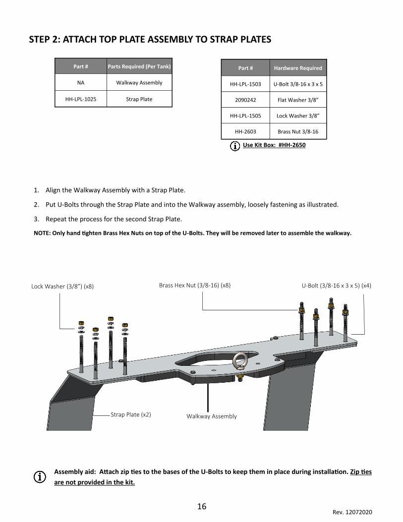
STEP 2: ATTACH TOP PLATE ASSEMBLY TO STRAP PLATES
1. Align the Walkway Assembly with a Strap Plate.
2. Put U-Bolts through the Strap Plate and into the Walkway assembly, loosely fastening as illustrated.
3. Repeat the process for the second Strap Plate.
NOTE: Only hand tighten Brass Hex Nuts on top of the U-Bolts. They will be removed later to assemble the walkway.
Lock Washer (3/8”) (x8) Brass Hex Nut (3/8-16) (x8) U-Bolt (3/8-16 x 3 x 5) (x4)
Strap Plate (x2) Walkway Assembly
Part # Parts Required (Per Tank)
NA Walkway Assembly
HH-LPL-1025 Strap Plate
Part # Hardware Required
HH-LPL-1503 U-Bolt 3/8-16 x 3 x 5
2090242 Flat Washer 3/8”
HH-LPL-1505 Lock Washer 3/8”
HH-2603 Brass Nut 3/8-16
Assembly aid: Attach zip ties to the bases of the U-Bolts to keep them in place during installation. Zip ties
are not provided in the kit.
Use Kit Box: #HH-2650

17 Rev. 12072020
STEP 3: ATTACH TANK FRAME BRACKETS TO STRAP PLATES
U-Bolt
Support Channel
Bottom Gasket Nylon Bushing (2)
Flathead Bolt
Attach Zip Ties
Part # Parts Required (Per Tank)
HH-LPL-1040 Channel Support
HH-LPL-1027 Bottom Gasket
HH-LPL-1025 Strap Plate
Part # Hardware Required
HH-LPL-1504 U-Bolt (3/8-16 x 3 x 6)
HH-LPL-1006 Flat Head Bolt (5” SS)
HH-LPL-1031 Nylon HH Tank Bushing
H-1926 Hex Nut (1/2-13 Brass)
HH-1916 Lock Washer
1. Align the mounting holes for the Channel Support, Strap Plate, and Bottom Gasket.
2. Slide the U-Bolts through the bottom of the Channel Support.
Assembly Aid: Attach Zip Ties to the bases of the U-Bolts to keep them in place during installation. Zip Ties are
not provided in the kit.
3. Insert the 5” Flat Head Bolt through the Channel Support and the Bottom Gasket.
IMPORTANT: Tighten the Nuts against the Nylon Bushing so the Bolts cannot rotate before assembling into the
tank. This will make it easier to assemble the Bottom Gasket in Step 4.
Use Kit Box: #HH-2650
Lock washer
Hex Nut
Lock washer
Hex Nut
Strap
18 Rev. 12072020
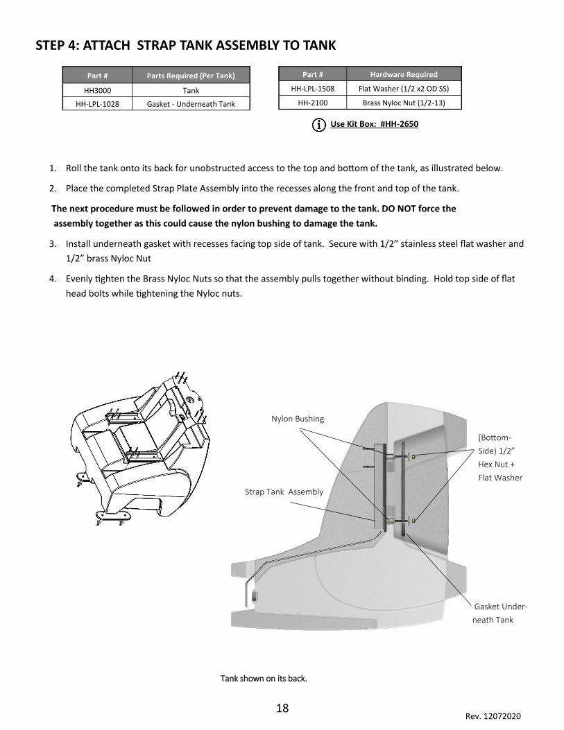
STEP 4: ATTACH STRAP TANK ASSEMBLY TO TANK
Tank shown on its back.
Part # Parts Required (Per Tank)
HH3000 Tank
HH-LPL-1028 Gasket - Underneath Tank
Part # Hardware Required
HH-LPL-1508 Flat Washer (1/2 x2 OD SS)
HH-2100 Brass Nyloc Nut (1/2-13)
Strap Tank Assembly
Gasket Under-
neath Tank
(Bottom-
Side) 1/2”
Hex Nut +
Flat Washer
Nylon Bushing
Use Kit Box: #HH-2650
1. Roll the tank onto its back for unobstructed access to the top and bottom of the tank, as illustrated below.
2. Place the completed Strap Plate Assembly into the recesses along the front and top of the tank.
The next procedure must be followed in order to prevent damage to the tank. DO NOT force the
assembly together as this could cause the nylon bushing to damage the tank.
3. Install underneath gasket with recesses facing top side of tank. Secure with 1/2” stainless steel flat washer and
1/2” brass Nyloc Nut
4. Evenly tighten the Brass Nyloc Nuts so that the assembly pulls together without binding. Hold top side of flat
head bolts while tightening the Nyloc nuts.
19 Rev. 12072020
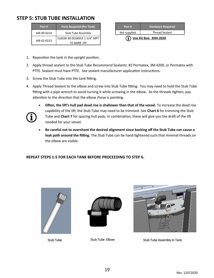
STEP 5: STUB TUBE INSTALLATION
1. Reposition the tank in the upright position.
2. Apply thread sealant to the Stub Tube Recommend Sealants: #2 Permatex, 3M 4200, or Permatex with
PTFE. Sealant must have PTFE. See sealant manufacturer application instructions.
3. Screw the Stub Tube into the tank fitting.
4. Apply Thread Sealant to the elbow and screw into Stub Tube fitting. You may need to hold the Stub Tube
fitting with a pipe wrench to avoid turning it while screwing in the elbow. As the threads tighten, pay
attention to the direction that the elbow /hose is pointing.
• Often, the lift’s hull pad dead rise is shallower than that of the vessel. To increase the dead rise
capability of the lift, the Stub Tube may need to be trimmed. See Chart 6 for trimming the Stub
Tube and Chart 7 for spacing hull pads. In combination, these will give you the draft of the lift
needed for your vessel.
• Be careful not to overshoot the desired alignment since backing off the Stub Tube can cause a
leak path around the fitting. The Stub Tube can be hand tightened such that minimal threads on
the elbow are visible.
REPEAT STEPS 1-5 FOR EACH TANK BEFORE PROCEEDING TO STEP 6.
Part # Parts Required (Per Tank)
AIR-00-0214 Stub Tube Assembly
AIR-02-0213 ELBOW 90 DEGREEE 1-1/4” MPT
TO BARB –PP
Part # Hardware Required
Not supplied Thread Sealant
Stub Tube Assembly in Tank Stub Tube Stub Tube Elbow
Use Kit Box: #HH-2650

20 Rev. 12072020
STEP 5: STUB TUBE INSTALLATION (Continued)
Tanks sets are numbered from front to rear. Set 1 is the farthest forward.
Chart 6: STUB TUBE MAXIMUM TRIM PER TANK SET
Forward Front to Rear (in.) Aft
Model Lifts SET 1 SET 2 SET 3 SET 4 SET 5
8800 Short 0 1.5" 3"
12000 0 1" 2" 3"
12000 Shallow 0 1" 2" 3"
12000 Wide 0 1" 2" 3"
15000 0 1" 2" 3"
15000 Shallow 0 1" 2" 3"
15000 Wide 0 1" 2" 3"
18000 0 1" 2" 3"
18000 Long 0 1" 2" 3"
18000 Wide 0 0.75" 1.5" 2.25" 3"

21 Rev. 12072020
STEP 6(a): ALIGNING THE TANKS
Side Alignment
1. Align the tanks next to each other, five on each side, spacing them so the mooring rings are 68.25” apart. You may
want to use the full-length hull support bracket as a straight-edge to align the tanks. The hull support bracket is
used in a later step.
2. Align tanks opposite each other using the rules for minimum beam of lift or beam of boat. See Step 6(b) for proper
alignment. Verify the tanks are separated enough to accommodate the cross channel in STEP 6(c).
The minimum beam of the lift is calculated by adding 34IN. to the beam of the boat. If the lift uses AUX
tanks, the minimum beam of the lift is determined by the width of the AUX tank. Refer to Table 1.
When sizing the slip this way, it will leave a minimum of a 4IN. gap for each of the lifts. Near this width, the
walkway could catch on the edge of the dock while raising or lowering. Dock fenders are recommended to pre-
vent this. See Chart 1 for minimum lift widths.
4” 4”
68.25” 68.25” 68.25”
Be
am o
f Li
ft
AUX Tank Width

22 Rev. 12072020
3. Perform Steps 6(b) and (c). Verify equal length diagonals as you build from tank Set 1 to tank
Set 5 as shown below to ensure they are square.
4. After confirming the lift is square and all assembly for Steps 6(b) and (c) are completed, tighten all
hardware completely.
Set 1 Set 2 Set 1 Set 2 Set 3
Set 1 Set 2 Set 3 Set 4 Set 1 Set 2 Set 3 Set 4 Set 5
23 Rev. 12072020
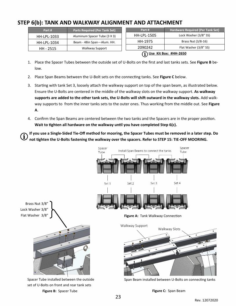
STEP 6(b): TANK AND WALKWAY ALIGNMENT AND ATTACHMENT
1. Place the Spacer Tubes between the outside set of U-Bolts on the first and last tanks sets. See Figure B be-
low.
2. Place Span Beams between the U-Bolt sets on the connecting tanks. See Figure C below.
3. Starting with tank Set 3, loosely attach the walkway support on top of the span beam, as illustrated below.
Ensure the U-Bolts are centered in the middle of the walkway slots on the walkway support. As walkway
supports are added to the other tank sets, the U-Bolts will shift outward in the walkway slots. Add walk-
way supports to from the inner tanks sets to the outer ones. Thus working from the middle out. See Figure
A.
4. Confirm the Span Beams are centered between the two tanks and the Spacers are in the proper position.
Wait to tighten all hardware on the walkway until you have completed Step 6(c).
If you use a Single-Sided Tie-Off method for mooring, the Spacer Tubes must be removed in a later step. Do
not tighten the U-Bolts fastening the walkway over the spacers. Refer to STEP 15: TIE-OFF MOORING.
Span Beam installed between U-Bolts on connecting tanks
Walkway Support Walkway Slots
Figure C: Span Beam
Spacer Tube installed between the outside
set of U-Bolts on front and rear tank sets
Figure B: Spacer Tube
Brass Nut 3/8”
Lock Washer 3/8”
Flat Washer 3/8” Figure A: Tank Walkway Connection
Part # Parts Required (Per Tank Set)
HH-LPL-1033 Aluminum Spacer Tube (3 X 3)
HH-LPL-1034 Beam - 48in Span—Alum. HH.
HH - 2515 Walkway Support
Part # Hardware Required (Per Tank Set)
HH-LPL-1505 Lock Washer (3/8” SS)
HH-1975 Brass Nut (3/8-16)
2090242 Flat Washer (3/8” SS)
Use Kit Box: #HH-2650
24 Rev. 12072020
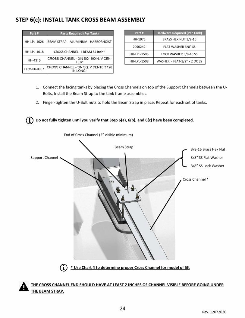
STEP 6(c): INSTALL TANK CROSS BEAM ASSEMBLY
Part # Parts Required (Per Tank)
HH-LPL-1026 BEAM STRAP—ALUMINUM –HARBORHOIST
HH-LPL-1018 CROSS CHANNEL - I BEAM 84 inch*
HH-4310 CROSS CHANNEL - 3IN SQ. 100IN. V CEN-
TER*
FRM-06-0007 CROSS CHANNEL - 3IN SQ. V CENTER 126
IN LONG*
Part # Hardware Required (Per Tank)
HH-1975 BRASS HEX NUT 3/8-16
2090242 FLAT WASHER 3/8” SS
HH-LPL-1505 LOCK WASHER 3/8-16 SS
HH-LPL-1508 WASHER - FLAT-1/2" x 2 OC SS
1. Connect the facing tanks by placing the Cross Channels on top of the Support Channels between the U-
Bolts. Install the Beam Strap to the tank frame assemblies.
2. Finger-tighten the U-Bolt nuts to hold the Beam Strap in place. Repeat for each set of tanks.
Do not fully tighten until you verify that Step 6(a), 6(b), and 6(c) have been completed.
Support Channel
Beam Strap 3/8-16 Brass Hex Nut
3/8” SS Flat Washer
3/8” SS Lock Washer
Cross Channel *
THE CROSS CHANNEL END SHOULD HAVE AT LEAST 2 INCHES OF CHANNEL VISIBLE BEFORE GOING UNDER
THE BEAM STRAP.
End of Cross Channel (2” visible minimum)
* Use Chart 4 to determine proper Cross Channel for model of lift
25 Rev. 12072020
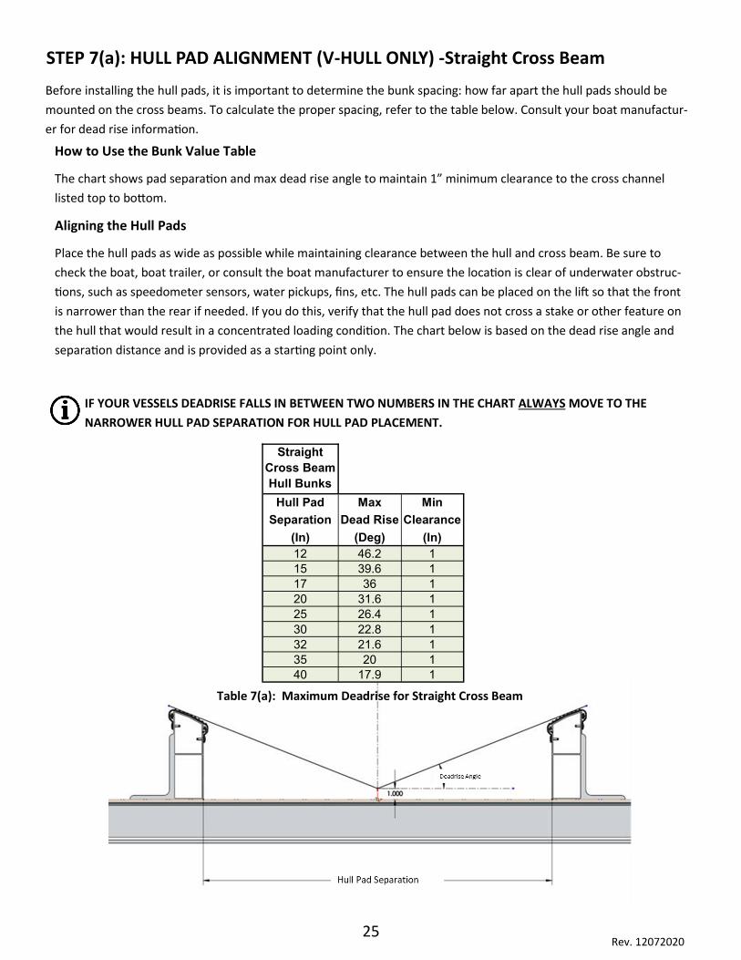
STEP 7(a): HULL PAD ALIGNMENT (V-HULL ONLY) -Straight Cross Beam
Before installing the hull pads, it is important to determine the bunk spacing: how far apart the hull pads should be
mounted on the cross beams. To calculate the proper spacing, refer to the table below. Consult your boat manufactur-
er for dead rise information.
How to Use the Bunk Value Table
The chart shows pad separation and max dead rise angle to maintain 1” minimum clearance to the cross channel
listed top to bottom.
Aligning the Hull Pads
Place the hull pads as wide as possible while maintaining clearance between the hull and cross beam. Be sure to
check the boat, boat trailer, or consult the boat manufacturer to ensure the location is clear of underwater obstruc-
tions, such as speedometer sensors, water pickups, fins, etc. The hull pads can be placed on the lift so that the front
is narrower than the rear if needed. If you do this, verify that the hull pad does not cross a stake or other feature on
the hull that would result in a concentrated loading condition. The chart below is based on the dead rise angle and
separation distance and is provided as a starting point only.
IF YOUR VESSELS DEADRISE FALLS IN BETWEEN TWO NUMBERS IN THE CHART ALWAYS MOVE TO THE
NARROWER HULL PAD SEPARATION FOR HULL PAD PLACEMENT.
Table 7(a): Maximum Deadrise for Straight Cross Beam
Straight
Cross Beam
Hull Bunks
Hull Pad Max Min
Separation Dead Rise Clearance
(In) (Deg) (In)
12 46.2 1
15 39.6 1
17 36 1
20 31.6 1
25 26.4 1
30 22.8 1
32 21.6 1
35 20 1
40 17.9 1

26 Rev. 12072020
STEP 7(a): HULL PAD ALIGNMENT (V-HULL ONLY) - V Center Cross Beam
Before installing the hull pads, it is important to determine the bunk spacing: how far apart the hull pads should be
mounted on the cross beams. To calculate the proper spacing, refer to the table below. Consult your boat manufactur-
er for dead rise information.
How to Use the Bunk Value Table
The chart shows pad separation and max dead rise angle to maintain 1” minimum clearance to the cross channel
listed top to bottom.
Aligning the Hull Pads
Place the hull pads as wide as possible while maintaining clearance between the hull and cross beam. Be sure to
check the boat, boat trailer, or consult the boat manufacturer to ensure the location is clear of underwater obstruc-
tions, such as speedometer sensors, water pickups, fins, etc. The hull pads can be placed on the lift so that the front
is narrower than the rear if needed. If you do this, verify that the hull pad does not cross a stake or other feature on
the hull that would result in a concentrated loading condition. The chart below is based on the dead rise angle and
separation distance and is provided as a starting point only.
IF YOUR VESSELS DEADRISE FALLS IN BETWEEN TWO NUMBERS IN THE CHART ALWAYS MOVE TO THE
NARROWER HULL PAD SEPARATION FOR HULL PAD PLACEMENT.
Table 7(a): Maximum Deadrise for V-Center Cross Beam
V-Center
Cross Beam
Hull Bunks
Hull Pad Max Min
Separation Deadrise Clearance
(In) (Deg) (In)
25 35.5 1
30 30.7 1
32 29.2 1
35 27 1
40 24.3 1

27 Rev. 12072020
1. After confirming the proper spacing, place the angle entry Hull Pad at the back edge of the entry Cross
Channel. Hold it in place with an 18” bar clamp.
2. Mount the Hull Pad to the cross channel using the U-Bolts, Lock Washers, and Brass Nuts. Drill a 7/16"
hole through the Hull Pad to connect the U-Bolts to the Cross Channel.
3. Repeat these steps for the opposite side Hull Pad.
In some applications, the Hull Pad will align such that the Hull Support Bracket is directly over the AUX
tank I-beam. If this occurs, use 3/8” x 5.5” bolts (not supplied) to bolt the support bracket directly to the I-
Beam, sandwiching the Cross Beam between the Hull Support Bracket and the I-Beam. The U-Bolts are
Discarded. Use the U-bolt Nuts and Washers with these Bolts.
STEP 7(b): MOUNTING THE HULL PADS (V-HULL ONLY)
Hull Pad
U-Bolt .375 x 3 x 5
Washer-FLT 3/8”
Lock Washer 3/8”
Part # Parts Required
1035066 Assy HarborHoist AL Bunk Left 22FT
1035067 Assy HarborHoist AL Bunk Right 22FT
Part # Hardware Required
HH-2603 Nut 3/8"-16 Brass
2090242 Washer - Flat -3/8" SS
HH-LPL-1505 Lock Washer 3/8" SS
HH-LPL-1503 U-Bolt - .375x3x5 SS
Use Kit Boxes #1035195
28 Rev. 12072020
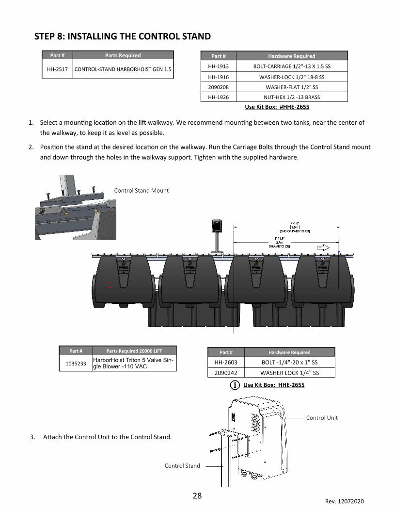
1. Select a mounting location on the lift walkway. We recommend mounting between two tanks, near the center of
the walkway, to keep it as level as possible.
2. Position the stand at the desired location on the walkway. Run the Carriage Bolts through the Control Stand mount
and down through the holes in the walkway support. Tighten with the supplied hardware.
STEP 8: INSTALLING THE CONTROL STAND
3. Attach the Control Unit to the Control Stand.
Control Unit
Control Stand
Control Stand Mount
Part # Hardware Required
HH-1913 BOLT-CARRIAGE 1/2"-13 X 1.5 SS
HH-1916 WASHER-LOCK 1/2" 18-8 SS
2090208 WASHER-FLAT 1/2" SS
HH-1926 NUT-HEX 1/2 -13 BRASS
Part # Parts Required
HH-2517 CONTROL-STAND HARBORHOIST GEN 1.5
Part # Parts Required 20000 LIFT
1035233 HarborHoist Triton 5 Valve Sin-gle Blower -110 VAC
Part # Hardware Required
HH-2603 BOLT -1/4"-20 x 1" SS
2090242 WASHER LOCK 1/4" SS
Use Kit Box: #HHE-2655
Use Kit Box: HHE-2655
29 Rev. 12072020
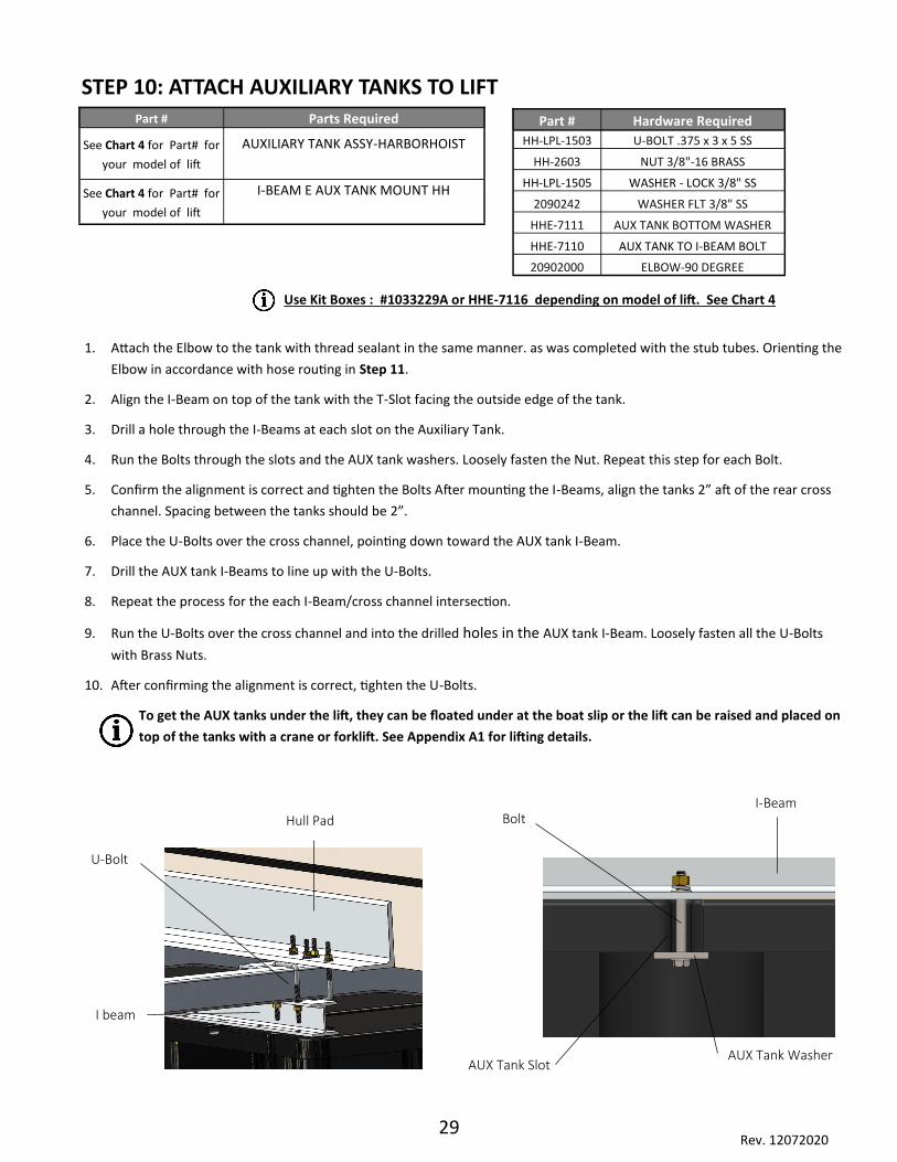
STEP 10: ATTACH AUXILIARY TANKS TO LIFT
1. Attach the Elbow to the tank with thread sealant in the same manner. as was completed with the stub tubes. Orienting the
Elbow in accordance with hose routing in Step 11.
2. Align the I-Beam on top of the tank with the T-Slot facing the outside edge of the tank.
3. Drill a hole through the I-Beams at each slot on the Auxiliary Tank.
4. Run the Bolts through the slots and the AUX tank washers. Loosely fasten the Nut. Repeat this step for each Bolt.
5. Confirm the alignment is correct and tighten the Bolts After mounting the I-Beams, align the tanks 2” aft of the rear cross
channel. Spacing between the tanks should be 2”.
6. Place the U-Bolts over the cross channel, pointing down toward the AUX tank I-Beam.
7. Drill the AUX tank I-Beams to line up with the U-Bolts.
8. Repeat the process for the each I-Beam/cross channel intersection.
9. Run the U-Bolts over the cross channel and into the drilled holes in the AUX tank I-Beam. Loosely fasten all the U-Bolts
with Brass Nuts.
10. After confirming the alignment is correct, tighten the U-Bolts.
To get the AUX tanks under the lift, they can be floated under at the boat slip or the lift can be raised and placed on
top of the tanks with a crane or forklift. See Appendix A1 for lifting details.
U-Bolt
I beam
Hull Pad I-Beam
Bolt
AUX Tank Washer AUX Tank Slot
Part # Parts Required
See Chart 4 for Part# for
your model of lift
AUXILIARY TANK ASSY-HARBORHOIST
See Chart 4 for Part# for
your model of lift
I-BEAM E AUX TANK MOUNT HH
Part # Hardware Required
HH-LPL-1503 U-BOLT .375 x 3 x 5 SS
HH-2603 NUT 3/8"-16 BRASS
HH-LPL-1505 WASHER - LOCK 3/8" SS
2090242 WASHER FLT 3/8" SS
HHE-7111 AUX TANK BOTTOM WASHER
HHE-7110 AUX TANK TO I-BEAM BOLT
20902000 ELBOW-90 DEGREE
Use Kit Boxes : #1033229A or HHE-7116 depending on model of lift. See Chart 4

30 Rev. 12072020
STEP 11: INSTALL HOSE SYSTEM
When running hoses, as recommended in Figures 3 & 4, avoid making dips “p-traps” in the routing of the lines. If
water gets in the air system, it can pool in these “p-traps”, which could cause an obstruction of the airline, resulting
in a reduction in lifting and lowering performance. Also, avoid running lines between tanks that could pinch the
hoses as they inflate
We recommend using the supplied hose labels when plumbing the air system to ensure the hoses are connected to
the correct port on the control unit.
Connecting Front Tanks
1. Run hoses from the Stub Tubes on the front two portside tanks to a tee. Center the tee between the 2 front
portside tanks and make sure hoses are equal length. Then, run a hose from the tee to the Front Port connection
on the Control Unit.
2. Connect hoses from the Stub Tubes on the front two starboard tanks to a tee. Center the tee between the 2 front
starboard tanks and make sure hoses are equal length. Then, run a hose from the tee to the Front Starboard con-
nection on the Control Unit.
Connecting Rear Tanks
1. Connect hoses from the Stub Tubes on the third and fourth rear port tanks together via a tee. Center the tee be-
tween the 2 portside tanks and make sure hoses are equal length. Then, run a hose from the tee to another tee
connected to the rear port tank.
2. Run a hose from the tee on the rear port tank to the Rear Port connection on the Control Unit.
3. Connect hoses from the Stub Tubes on the third and fourth rear starboard tanks together via a tee. Center the tee
between the 2 starboard tanks and make sure hoses are equal length. Then, run a hose from the tee to another
tee connected to the rear Starboard tank.
4. Run a hose from the tee on the rear Starboard tank to the Rear Port connection on the Control Unit.
AUX Tanks
1. Run a hose from the front AUX tank to one of the AUX Ports on the Control Unit.
2. Connect the other AUX tanks to a tee and then run a hose from that tee to the other AUX Port on the Control Unit.
Hose Labels
Part # Hardware Required
2093005 TEE-HOSE 1 1/4" BARBED NYLON
2090907 HOSE CLAMP
3072517 HOSE-RUBBER 1 1/4" id x 100FT. CUT
3072512 HOSE-RUBBER 1 1/4" id x 30FT. CUT
3072516 HOSE-RUBBER 1 1/4" id x 50FT. CUT
Use Kit Box: #HH-2685
These models will uses a 5
valve control with one AUX
port.
Part # Parts Required
1035233 HarborHoist Triton 5 Valve Single Blower -110 volt

31 Rev. 12072020
Figure 1: 8800 LB. (Short) HOSE ROUTING DIAGRAM
Figure 2: 12000 LB. HOSE ROUTING DIAGRAM
T = Tee (NOTE: Typical hose length from Stub Tube to tee is between 36" and 38")
T
T = Tee (NOTE: Typical hose length from Stub Tube to tee is between 36" and 38")
T
T T
T T
Stern
Stern

32 Rev. 12072020
Figure 3: 12000 LB. (Shallow) HOSE ROUTING DIAGRAM
Figure 4: 12000 LB. (Wide) HOSE ROUTING DIAGRAM
T = Tee (NOTE: Typical hose length from Stub Tube to tee is between 36" and 38")
T = Tee (NOTE: Typical hose length from Stub Tube to tee is between 36" and 38")
T T
T T
Stern
T T
T T
Stern

33 Rev. 12072020
Figure 5: 15000 LB. HOSE ROUTING DIAGRAM
Figure 6: 15000 LB. (Shallow) HOSE ROUTING DIAGRAM
T = Tee (NOTE: Typical hose length from Stub Tube to tee is between 36" and 38")
T = Tee (NOTE: Typical hose length from Stub Tube to tee is between 36" and 38")
T T
T T
Stern
T
T T
T T
Stern
T
34 Rev. 12072020
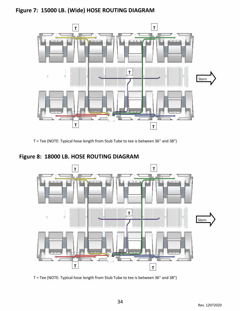
Figure 7: 15000 LB. (Wide) HOSE ROUTING DIAGRAM
Figure 8: 18000 LB. HOSE ROUTING DIAGRAM
T = Tee (NOTE: Typical hose length from Stub Tube to tee is between 36" and 38")
T = Tee (NOTE: Typical hose length from Stub Tube to tee is between 36" and 38")
T T
T T
Stern
T
T T
T T
Stern
T
35 Rev. 12072020
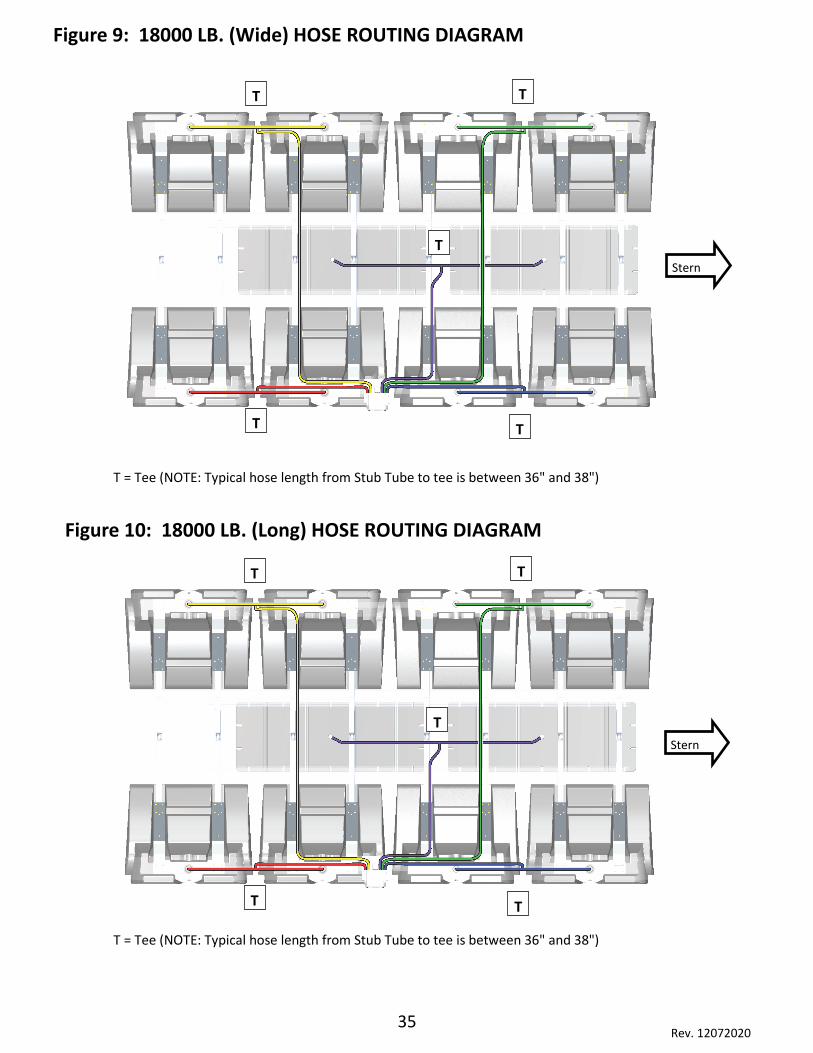
Figure 9: 18000 LB. (Wide) HOSE ROUTING DIAGRAM
Figure 10: 18000 LB. (Long) HOSE ROUTING DIAGRAM
T = Tee (NOTE: Typical hose length from Stub Tube to tee is between 36" and 38")
T = Tee (NOTE: Typical hose length from Stub Tube to tee is between 36" and 38")
T T
T T
Stern
T
T T
T T
Stern
T
36 Rev. 12072020
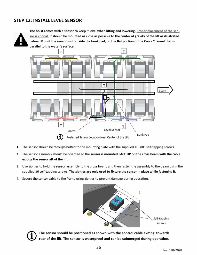
STEP 12: INSTALL LEVEL SENSOR
Preferred Sensor Location Near Center of the Lift
The hoist comes with a sensor to keep it level when lifting and lowering. Proper placement of the sen-
sor is critical. It should be mounted as close as possible to the center of gravity of the lift as illustrated
below. Mount the sensor just outside the bunk pad, on the flat portion of the Cross Channel that is
parallel to the water’s surface.
1. The sensor should be through-bolted to the mounting plate with the supplied #6 3/8” self-tapping screws.
2. The sensor assembly should be oriented so the sensor is mounted FACE UP on the cross beam with the cable
exiting the sensor aft of the lift.
3. Use zip ties to hold the sensor assembly to the cross beam, and then fasten the assembly to the beam using the
supplied #6 self-tapping screws. The zip ties are only used to fixture the sensor in place while fastening it.
4. Secure the sensor cable to the frame using zip ties to prevent damage during operation.
The sensor should be positioned as shown with the control cable exiting towards
rear of the lift. The sensor is waterproof and can be submerged during operation.
Self-tapping
screws
T T
T T
Stern
T
Bunk Pad
Level Sensor
Control
37 Rev. 12072020
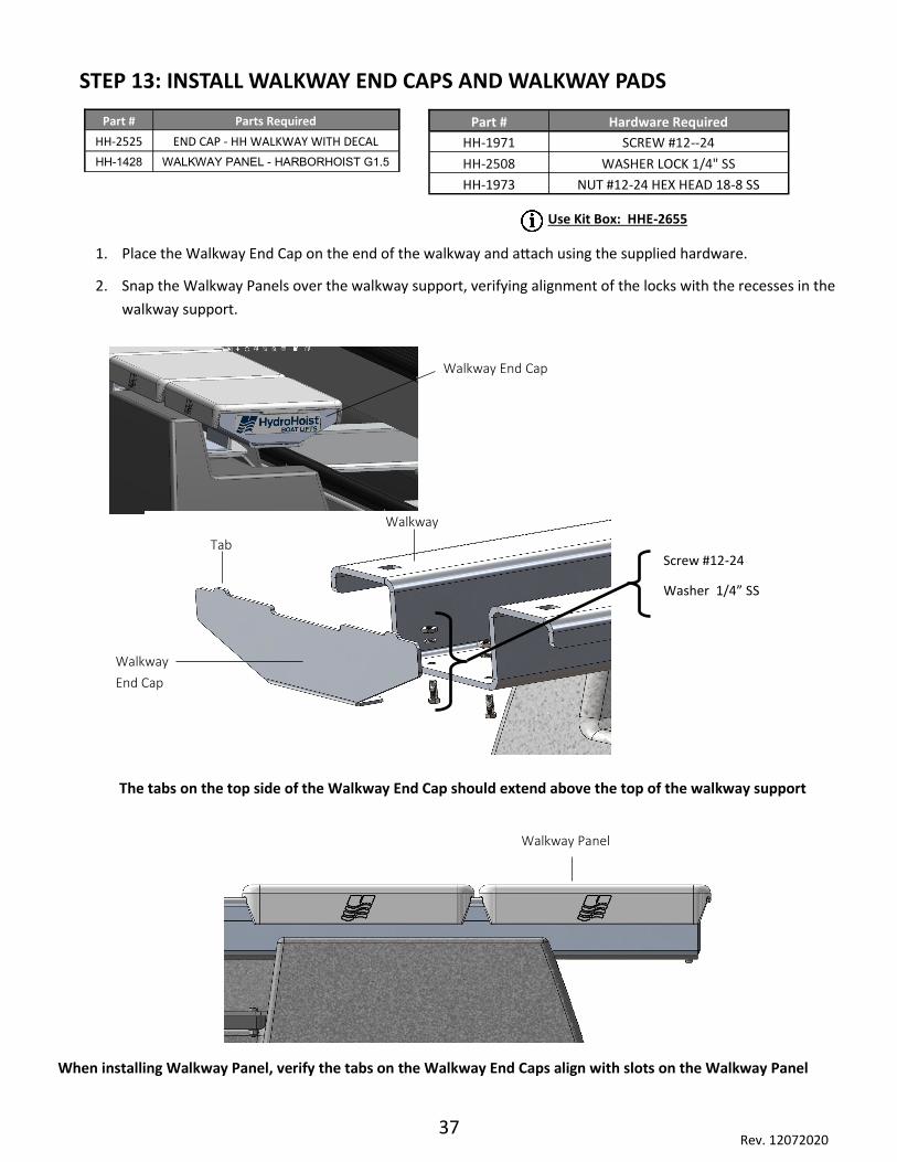
1. Place the Walkway End Cap on the end of the walkway and attach using the supplied hardware.
2. Snap the Walkway Panels over the walkway support, verifying alignment of the locks with the recesses in the
walkway support.
STEP 13: INSTALL WALKWAY END CAPS AND WALKWAY PADS
Walkway End Cap
Walkway Panel
Part # Parts Required
HH-2525 END CAP - HH WALKWAY WITH DECAL
HH-1428 WALKWAY PANEL - HARBORHOIST G1.5
Part # Hardware Required
HH-1971 SCREW #12--24
HH-2508 WASHER LOCK 1/4" SS
HH-1973 NUT #12-24 HEX HEAD 18-8 SS
Walkway
End Cap
Tab
Walkway
Screw #12-24
Washer 1/4” SS
Use Kit Box: HHE-2655
The tabs on the top side of the Walkway End Cap should extend above the top of the walkway support
When installing Walkway Panel, verify the tabs on the Walkway End Caps align with slots on the Walkway Panel

38 Rev. 12072020
STEP 14: TIE-OFF MOORING (MOORING ROPES NOT INCLUDED)
Single-Sided Tie Off (Optional)
1. Attach Side-Tie bumper pipe to the Side-Tie Bumper Bracket
using the supplied U-Bolt and Mounting Plate.
2. Replace the end spacer tubes with the Side-Tie Bumper.
3. Replace the spacers on the end tanks with the Side-Tie Bumper.
4. Attach the walkway support. For more information, refer to STEP
8: TANK AND WALKWAY ALIGNMENT/ATTACHMENT.
Tie off the lift using a method similar to mooring a boat in a slip. The goal is to restrain the lift as much as
possible while leaving enough slack in the lines to allow the lift to raise and lower properly.
NOTE: Use a good mooring rope with enough strength for the size of boat and lift being installed. Use a
minimum rope diameter of 3/8” for boats up to 25’, 1/2” for boats up to 35’, and 5/8” for boats up to 45’.
There are several variables involved in rope selection and tie-off locations, so check the mooring regularly for any
changes in rope condition, tie-off points, etc.
Be sure that all tie-off points are in good condition and structurally sound enough to handle the load the mooring will
apply. We recommend Double Braid Nylon Dock lines.
Parts Required Hardware Required
Side-Tie Bumper (not supplied) U-Bolt with Mounting Plate
Side-Tie Bumper Pipe (not supplied)
Mounting Plate
Bumper Pipe
Side-Tie Bumper

39 Rev. 12072020
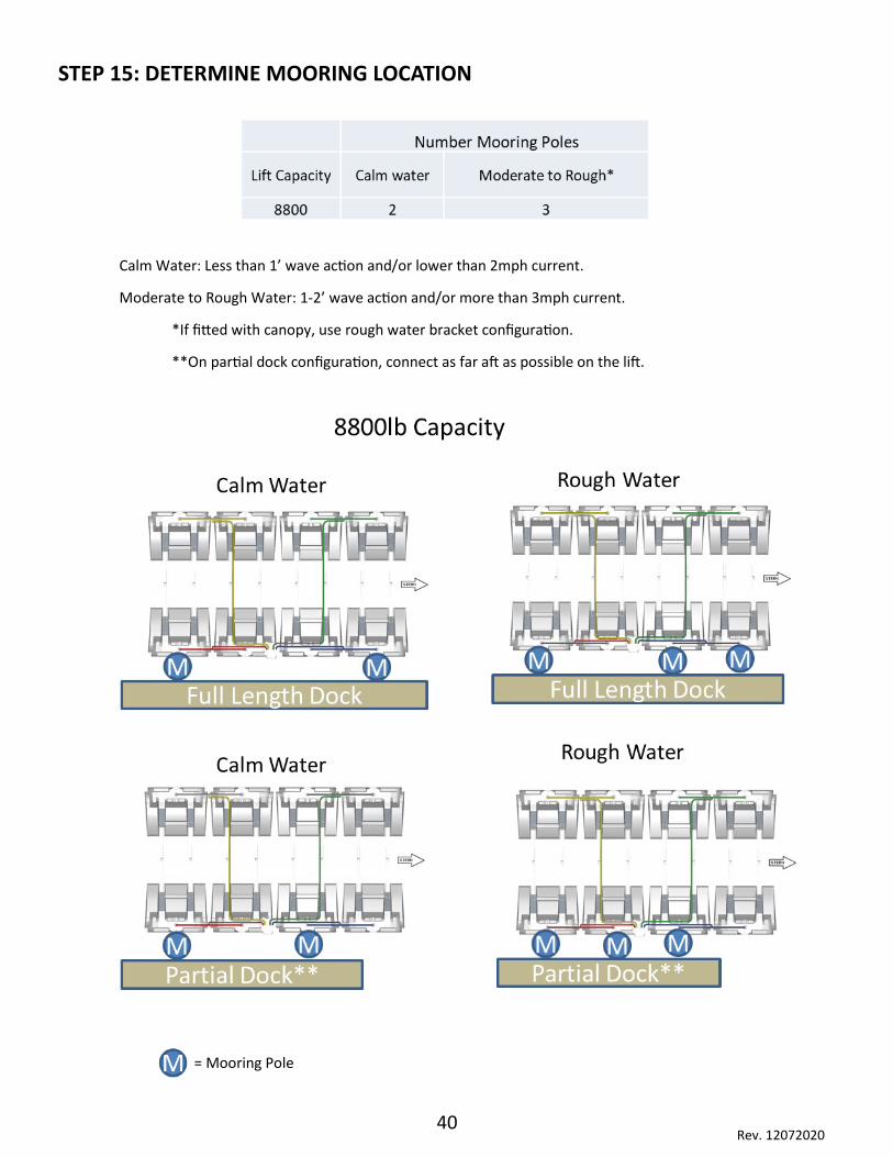
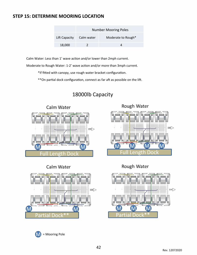
STEP 15: DETERMINE MOORING LOCATION
= Mooring Pole
Calm Water: Less than 1’ wave action and/or lower than 2mph current.
Moderate to Rough Water: 1-2’ wave action and/or more than 3mph current.
*If fitted with canopy, use rough water bracket configuration.
**On partial dock configuration, connect as far aft as possible on the lift.
Number Mooring Poles
Lift Capacity Calm water Moderate to Rough*
15,000 2 3
40 Rev. 12072020
STEP 15: DETERMINE MOORING LOCATION
= Mooring Pole
Calm Water: Less than 1’ wave action and/or lower than 2mph current.
Moderate to Rough Water: 1-2’ wave action and/or more than 3mph current.
*If fitted with canopy, use rough water bracket configuration.
**On partial dock configuration, connect as far aft as possible on the lift.
41 Rev. 12072020
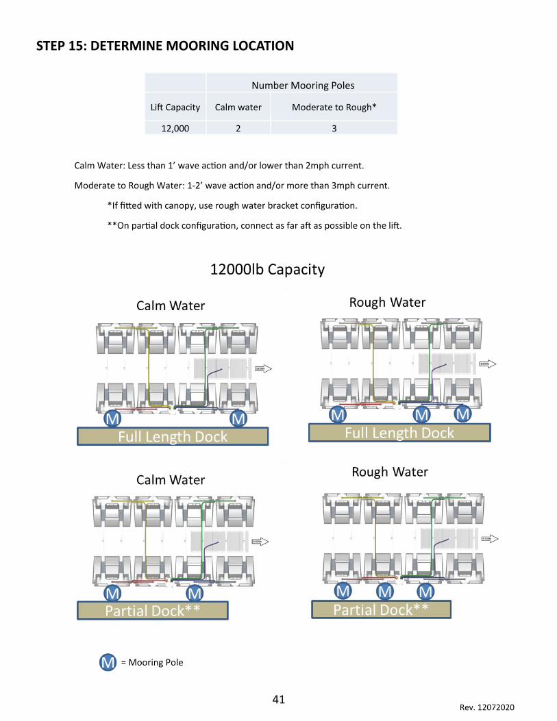
STEP 15: DETERMINE MOORING LOCATION
= Mooring Pole
Calm Water: Less than 1’ wave action and/or lower than 2mph current.
Moderate to Rough Water: 1-2’ wave action and/or more than 3mph current.
*If fitted with canopy, use rough water bracket configuration.
**On partial dock configuration, connect as far aft as possible on the lift.
Number Mooring Poles
Lift Capacity Calm water Moderate to Rough*
12,000 2 3
42 Rev. 12072020
STEP 15: DETERMINE MOORING LOCATION
= Mooring Pole
Calm Water: Less than 1’ wave action and/or lower than 2mph current.
Moderate to Rough Water: 1-2’ wave action and/or more than 3mph current.
*If fitted with canopy, use rough water bracket configuration.
**On partial dock configuration, connect as far aft as possible on the lift.
Number Mooring Poles
Lift Capacity Calm water Moderate to Rough*
18,000 2 4
43 Rev. 12072020
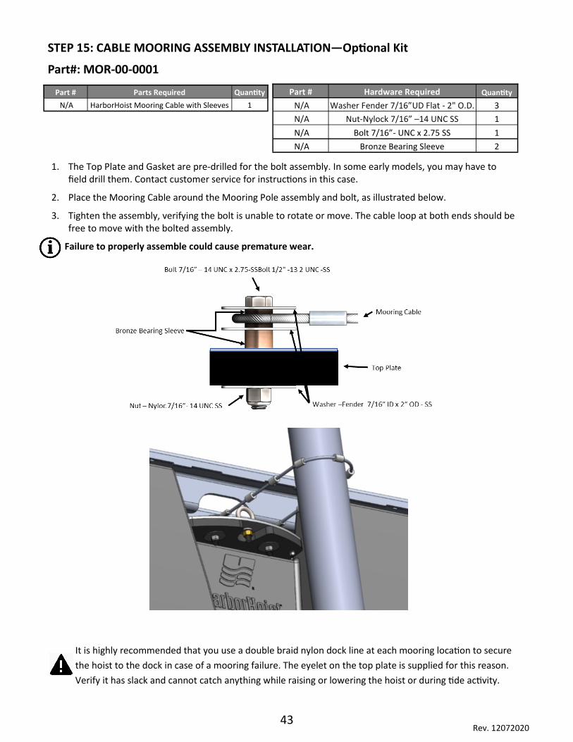
1. The Top Plate and Gasket are pre-drilled for the bolt assembly. In some early models, you may have to field drill them. Contact customer service for instructions in this case.
2. Place the Mooring Cable around the Mooring Pole assembly and bolt, as illustrated below.
3. Tighten the assembly, verifying the bolt is unable to rotate or move. The cable loop at both ends should be free to move with the bolted assembly.
Failure to properly assemble could cause premature wear.
STEP 15: CABLE MOORING ASSEMBLY INSTALLATION—Optional Kit
Part#: MOR-00-0001
It is highly recommended that you use a double braid nylon dock line at each mooring location to secure
the hoist to the dock in case of a mooring failure. The eyelet on the top plate is supplied for this reason.
Verify it has slack and cannot catch anything while raising or lowering the hoist or during tide activity.
Part # Hardware Required Quantity
N/A Washer Fender 7/16”UD Flat - 2" O.D. 3
N/A Nut-Nylock 7/16” –14 UNC SS 1
N/A Bolt 7/16”- UNC x 2.75 SS 1
N/A Bronze Bearing Sleeve 2
Part # Parts Required Quantity
N/A HarborHoist Mooring Cable with Sleeves 1
44 Rev. 12072020
Commissioning the Lift
Damage to the lift or vessel can result from improper initial setup of the system.
Consult a HydroHoist approved installer for initial setup and support.
• Installation and service should be performed by a qualified service professional.
• To lessen the risk of electric shock, disconnect the control box from power during installation.
• The GFCI supplied with the control is designed for outdoor applications but is NOT to be submerged or
directly sprayed with water by the exhaust port of the control box.
• Verify that the power receptacle is clean and supplies the proper current for the controller.
• Keep children away from setup and assembly.
• Do not become distracted or walk away from the lift during operation.
• Do not overload the lift. Make certain your boat’s bilge pump is set for automatic. Significant water
accumulation in the bilge may overload the lift.
• Make sure ballast tanks are empty before lifting the boat.
• Lift is not designed to hoist the boat with people in it.
• Never allow a person to be under the boat and/or hoist.
• Weight must be distributed equally side to side and bow to stern before lifting. Otherwise, the boat will
not center properly and could be misaligned on the lift.
Before commissioning the hoist, read the Operation Manual completely to familiarize yourself
with all the functions and features of the control box.
IF your control was purchased after July 2020 please reference the HarborHoist Triton Owner Operator
Control Manual.

45 Rev. 12072020
STEP 18: COMMISSIONING THE LIFT
Perform the following steps after the lift has been installed, WITHOUT a vessel on the hoist.
1. With the lift completely lowered calibrate the level sensor. Please reference the HarborHoist Own-
er-Operating Manual for the procedure and functionality.
2. Raise the hoist until all main tanks are bubbling air. Stop the hoist. If the HarborHoist lifted level
then lower and position vessel on the lift. The next step may take some trial and error to the get
the vessel to balance properly on the lift. The best balance is with the center mass of the boat to
be within 6” of the center of buoyance of the lift. See the Appendix for location of each models cen-
ter of buoyance.
3. If the hoist does not raise level, lower the lift and reposition the vessel on the lift and re-raise. Do
this until the lift raises level or just slightly rear angled down so rain water can drain to the rear of
the vessel.
4. With the vessel fully raised recalibrate the level sensor. See the Owner-Operation Manual for the
procedure.
5. Lower and raise the lift once more to verify level operation.
6. While the hoist is completely raised, verify with soapy water that there are no leaks at any connec-
tion in the air system.
7. While in operation, inspect the lift for binding of ropes or mooring systems. Resolve any issues.
Please review the Operation Manual for a full list of features and troubling shooting procedures
46 Rev. 12072020
Boat Fitment Take care to clear shafts, through hull fittings, strakes, etc. The boat’s keel must NOT rest on a cross beam
and should clear the beam by at least 1”. The boat’s Center of Gravity (CG) must be in the center of the lift
(unless AUX tanks are used) bow to stern and port to starboard. This evenly distributes the load over the
lift, allowing for maximum lift height and level operation.
The CG of the boat, when located with the transom at the end of the lift, should never be forward of the
center (CG) of the lift. If this occurs, another set of Main Tanks may be needed. If the AUX tank is complete-
ly behind the CG of the boat, moving the tank farther back amplifies the lifting effect of the rear. If you
need to move the AUX tank back farther than the end of the lift, verify that you have enough space availa-
ble between the outdrives and the tanks to avoid damage to either.
It is the responsibility of the End User to ensure that:
• The lift is installed by a certified HydroHoist Installer
• The lift is operated in a safe manner
• Regular inspection is performed on the lift components
• Customer has read and understands all safety and warning labels
• Has been properly trained in the operation of the lift
No alterations or modifications may be made to HydroHoist equipment without the express
written consent of HydroHoist. Re-installation, adjusting the bunks, and/or adjusting the tank beam spac-
ing must be performed to the standards of HydroHoist. It is the obligation of the End User to inform all
equipment operators of the above conditions. Additional Owner Manuals and Safety Warning Decals are
available by request.

47 Rev. 12072020
Warranty and Registration
What Is Not Covered By This Warranty*
HydroHoist® does not warrant any product, component, or part
(a) That is not manufactured by HydroHoist®
(b) That is not installed or serviced by employees or contractors of HydroHoist® or an
Authorized HydroHoist® Dealer
(c) Damaged by failure to provide a suitable installation environment for the lift
(d) Damaged by use of the lift for purposes other than those for which it was designed
(e) Damaged by disasters such as but not limited to fire, flood, wind, and lightning
(f) Damaged by unauthorized attachments or modifications
(g) Damaged by operation, maintenance, or repair of the product contrary to written instruc-
tions of HydroHoist®
(h) Damaged during shipment
(i) Damaged by any other abuse or misuse by the user
(j) Which has an altered or defaced service number
*Terms and conditions can change without notice. For the latest warranty terms, contact HydroHoist
Customer Service at [email protected]
Parts and Customer Service Contact
Customer service, parts, and shipping: [email protected]
Product Registration
Verify that a HydroHoist® dealer registered your boat lift. If it is not registered, warranty support may
be limited. Visit www.boatlift.com to register your lift.

48 Rev. 12072020
Appendix
49 Rev. 12072020
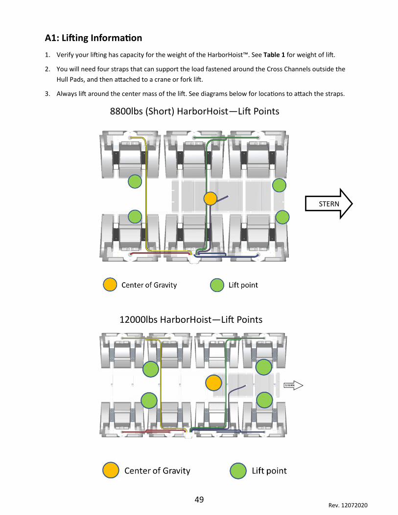
A1: Lifting Information
1. Verify your lifting has capacity for the weight of the HarborHoist™. See Table 1 for weight of lift.
2. You will need four straps that can support the load fastened around the Cross Channels outside the
Hull Pads, and then attached to a crane or fork lift.
3. Always lift around the center mass of the lift. See diagrams below for locations to attach the straps.
8800lbs (Short) HarborHoist—Lift Points
STERN
12000lbs HarborHoist—Lift Points

50 Rev. 12072020
A1: Lifting Information
1. Verify your lifting has capacity for the weight of the HarborHoist™. See Table 1 for weight of lift.
2. You will need four straps that can support the load fastened around the Cross Channels outside the
Hull Pads, and then attached to a crane or fork lift.
3. Always lift around the center mass of the lift. See diagrams below for locations to attach the straps.
15000lbs HarborHoist—Lift Points
18000lbs HarborHoist—Lift Points

51 Rev. 12072020