at4 wireless, s.a. - sos.state.co.us · report number : (nie) 39698rse.001 page 1 of 47 2013-12-13...
TRANSCRIPT

Report Number: (NIE) 39698RSE.001 Page 1 of 47 2013-12-13
AT4 wireless, S.A. Parque Tecnológico de Andalucía,
c/ Severo Ochoa nº 2 29590 Campanillas/ Málaga/ España Tel. 952 61 91 00 - Fax 952 61 91 13
MÁLAGA, C.I.F. A29 507 456 Registro Mercantil Tomo 3693 Libro 2604 Folio
174 Hoja MA3729
TEST REPORT
IEC 60950-1:2005 + CORR:2006 + A1:2009 EN 60950-1:2006 + A11:2009 + CORR:2006 +A1:2010 +A12:2011 + AC:2011
UNE EN 60950-1:2007 + A11_2009 + CORR:2007 +A12:2011 +AC:2012
Part 1: General requirements and tests
NIE ........................................................39698RSE.001
Approved by (name / position & signature) ................
Rafael Gonzalez / Consultant
..........................................................
Elaboration date ................................2013-12-13
Identification of item tested .................TECLA SHIELD DOS
Trademark .............................................TECLA
Model and/or type reference .................KOL-2001
Serial number ........................................Prototype
Features ..................................................3.7 V Battery supplied equipment
Description .............................................Wireless device to let control smartphones and tablets using external switches or the driving controls of the powered wheelchair. Equipment with insulating enclosure and protection against electric shock Class III.
Applicant ..............................................KOMODO OPENLAB INC.
Address ..................................................272 Winona Dr, Suite 2, Toronto M6C3S7 Ontario, Canada.
CIF/NIF/Passport ................................Not provided
Contact person........................................Jorge Silva
Telephone / Fax ................................ +1 (647) 210-0161 / Not provided
e-mail: [email protected]
Test samples supplier ..........................KOMODO OPENLAB INC.
Address ..................................................272 Winona Dr, Suite 2, Toronto M6C3S7 Ontario, Canada.
CIF/NIF/Passport ................................Not provided
Contact person: ................................ Jorge Silva
Telephone / Fax ................................ +1 (647) 210-0161 / Not provided
e-mail: [email protected]
Report Number: (NIE) 39698RSE.001 Page 2 of 47 2013-12-13
Manufacturer ................................KOMODO OPENLAB INC.
Address ..................................................272 Winona Dr, Suite 2, Toronto M6C3S7 Ontario, Canada.
CIF/NIF/Passport ................................Not provided
Telephone / Fax ................................ +1 (647) 210-0161 / Not provided
Test method requested
Standard .................................................IEC 60950-1:2005 + CORR:2006 + A1:2009
EN 60950-1:2006 + A11:2009 + CORR:2006 +A1:2010 +A12:2011 + AC:2011
UNE EN 60950-1:2007 + A11_2009 + CORR:2007 +A12:2011 +AC:2012
Test procedure .......................................POSE000 (General Procedure of Safety Lab)
Non-standardized test method ...............N/A
Report template No. .............................FSE00_15
AVISO IMPORTANTE: El presente documento forma una unidad indivisible y no puede ser reproducido parcialmente sin la aprobación por escrito AT4 wireless, S.A.
Report Number: (NIE) 39698RSE.001 Page 3 of 47 2013-12-13
INDEX
Competences and guarantees ................................................................................................................ 4
General conditions ................................................................................................................................ 4
Uncertainty ............................................................................................................................................ 4
Usage of samples................................................................................................................................... 4
Testing period ....................................................................................................................................... 4
Environmental conditions ..................................................................................................................... 5
Summary ............................................................................................................................................... 5
Remarks and comments ........................................................................................................................ 5
Personnel ............................................................................................................................................... 5
Used instruments ................................................................................................................................... 6
Testing veredicts ................................................................................................................................. 13
Particulars: test item vs. test requirements .......................................................................................... 13
Copy of the marking plate ................................................................................................................... 13
APPENDIX A: Results of test according to IEC 60950-1/ EN 60950-1 / UNE EN 60950-1 ............ 14
APPENDIX B: Photographs ............................................................................................................... 43
Report Number: (NIE) 39698RSE.001 Page 4 of 47 2013-12-13
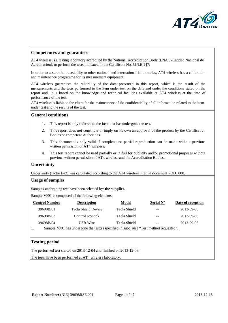
Competences and guarantees
AT4 wireless is a testing laboratory accredited by the National Accreditation Body (ENAC -Entidad Nacional de Acreditación), to perform the tests indicated in the Certificate No. 51/LE 147.
In order to assure the traceability to other national and international laboratories, AT4 wireless has a calibration and maintenance programme for its measurement equipment.
AT4 wireless guarantees the reliability of the data presented in this report, which is the result of the measurements and the tests performed to the item under test on the date and under the conditions stated on the report and, it is based on the knowledge and technical facilities available at AT4 wireless at the time of performance of the test. AT4 wireless is liable to the client for the maintenance of the confidentiality of all information related to the item under test and the results of the test.
General conditions
1. This report is only referred to the item that has undergone the test.
2. This report does not constitute or imply on its own an approval of the product by the Certification Bodies or competent Authorities.
3. This document is only valid if complete; no partial reproduction can be made without previous written permission of AT4 wireless.
4. This test report cannot be used partially or in full for publicity and/or promotional purposes without previous written permission of AT4 wireless and the Accreditation Bodies.
Uncertainty
Uncertainty (factor k=2) was calculated according to the AT4 wireless internal document PODT000.
Usage of samples
Samples undergoing test have been selected by: the supplier.
Sample M/01 is composed of the following elements:
Control Number Description Model Serial Nº Date of reception
39698B/01
39698B/03
39698B/04
Tecla Shield Device
Control Joystick
USB Wire
Tecla Shield
Tecla Shield
Tecla Shield
--
--
--
2013-09-06
2013-09-06
2013-09-06 1. Sample M/01 has undergone the test(s) specified in subclause “Test method requested”.
Testing period
The performed test started on 2013-12-04 and finished on 2013-12-06.
The tests have been performed at AT4 wireless laboratory.
Report Number: (NIE) 39698RSE.001 Page 5 of 47 2013-12-13
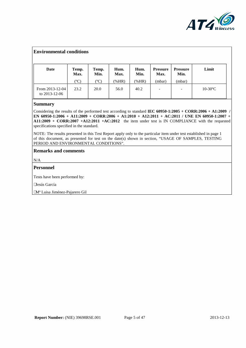
Environmental conditions
Date Temp. Max.
(ºC)
Temp. Min.
(ºC)
Hum. Max.
(%HR)
Hum. Min.
(%HR)
Pressure Max.
(mbar)
Pressure Min.
(mbar)
Limit
From 2013-12-04 to 2013-12-06
23.2 20.0 56.0 40.2 - - 10-30ºC
Summary
Considering the results of the performed test according to standard IEC 60950-1:2005 + CORR:2006 + A1:2009 / EN 60950-1:2006 + A11:2009 + CORR:2006 + A1:2010 + A12:2011 + AC:2011 / UNE EN 60950-1:2007 + A11:2009 + CORR:2007 +A12:2011 +AC:2012 the item under test is IN COMPLIANCE with the requested specifications specified in the standard.
NOTE: The results presented in this Test Report apply only to the particular item under test established in page 1 of this document, as presented for test on the date(s) shown in section, “USAGE OF SAMPLES, TESTING PERIOD AND ENVIRONMENTAL CONDITIONS”.
Remarks and comments
N/A
Personnel
Tests have been performed by:
⋅ Jesús García
⋅ Mª Luisa Jiménez-Pajarero Gil

Report Number: (NIE) 39698RSE.001 Page 6 of 47 2013-12-13
Used instruments ( ) 0049 Digital multimeter ( ) 1402 AC Power Supply 2000 V / 0.5 A
( ) 0055 Probe 100 MHz ( ) 1403 Deflex tester
(X) 0148 Digital multimeter ( ) 1404 Solution ClNH4 0.1 %
( ) 0151 Autotransformer ( ) 1406 Polyester
( ) 0154 Digital multimeter ( ) 1407 Digital wattmeter
( ) 0155 Digital multimeter ( ) 1409 Immersion resistor
( ) 0157 Digital multimeter ( ) 1410 Endurance Rack (MKT-S)
( ) 0159 Registrer UR180 ( ) 1411 Endurance Rack (MKT-S)
( ) 0161 Digital thermometer ( ) 1419 Talcum dust
( ) 0162 Digital thermometer ( ) 1424 Pulse Generator NSG2050
( ) 0164 Insulation transformer ( ) 1425 Impedance Box INA2057-1
( ) 0166 One-phase vatimeter ( ) 1426 Impedance Box INA2057-2
( ) 0170 Dielectric strength meter ( ) 1427 Impedance Box INA2057-3
( ) 0172 Low Resistance Meter ( ) 1428 Impedance Box INA2057-4
( ) 0175 Electronic load module ( ) 1429 Impedance Box INA2057-5
( ) 0176 Electronic load module ( ) 1430 Impedance Box INA2057-6
( ) 0177 Electronic load module ( ) 1431 Impedance Box INA2057-7
( ) 0179 Electronic Scales ( ) 1432 Impedance Box INA2057-8
( ) 0192 K-Type thermocouple ( ) 1434 Impedance Box INA2057-9
( ) 0193 K-Type thermocouple ( ) 1435 Components INA122 Tester
( ) 0194 K-Type thermocouple ( ) 1448 Power Analyser
( ) 0195 K-Type thermocouple ( ) 1459 Defibrillator
( ) 0230 Remote control ( ) 1463 Random-schock controller
( ) 0352 Mist chamber HSA1000 ( ) 1464 Incandescent E-27 master lamp
(X) 0353 Chamber VEM 03/5500/W/S ( ) 1465 Incancescent E-14 master lamp
( ) 0354 Thermal schock chamber VMS02/08/22/120
( ) 1466 Halogen master lamp
( ) 0356 Chamber HC7055 ( ) 1467 Light bulb master lamp
( ) 0369 Power amplifier ( ) 1468 Fluorescent tube master lamp
( ) 0370 Electrodynamic Vibration System ( ) 1475 Metallic surface 0.1 m2
( ) 0371 Accelerometer conditioning Unit ( ) 1480 Climactic chamber VEKZ 25/180
( ) 0372 Accelerometer ( ) 1481 Test circuit EN 60601-2-2
( ) 0375 Accelerometer ( ) 1490 Test circuit EN 60598-1
( ) 0377 Triaxial accelerometer ( ) 1492 Test ballast EN 60928
( ) 0421 K-Type thermocouple ( ) 1493 Test ballast EN 60598-1
( ) 0422 K-Type thermocouple ( ) 1506 Peacemaker Power Supply
( ) 0423 K-Type thermocouple ( ) 1510 Nail finger test
( ) 0424 K-Type thermocouple ( ) 1511 Grids 3,4,7,8
( ) 0425 K-Type thermocouple ( ) 1550 Chroming rod Ø20 mm
( ) 0426 K-Type thermocouple ( ) 1612 High current tester
( ) 0427 K-Type thermocouple ( ) 1615 Glass ball 1 – 1.4 mm

Report Number: (NIE) 39698RSE.001 Page 7 of 47 2013-12-13
Used instruments ( ) 0428 K-Type thermocouple ( ) 1620 Impact tester (fig. 22)
( ) 0430 K-Type thermocouple ( ) 1621 Abration tester. Pins (fig.24).
( ) 0431 Steel ball ( ) 1622 Force remove tester
( ) 0432 Gauges ( ) 1623 Anchorage cable tester (fig. 15)
(X) 0434 Accessibility probe ( ) 1624 Switch tester
(X) 0435 Test finger ( ) 1627 Oven AFA-150
( ) 0436 Contact indicator ( ) 1629 Oven AFA-150
(X) 0437 Dinamometer push pull 0-50 N ( ) 1630 Oven AFA-150
( ) 0438 Dinamometer push pull 0-100 N ( ) 1631 Oven AFA-150
( ) 0439 Dinamometer push pull 0-250 N ( ) 1632 Oven AFA-150
( ) 0440 Test hood ( ) 1635 Luxometer
( ) 0441 Ball pressure apparatus ( ) 1636 PV probe
( ) 0457 Test probe Ø30 mm ( ) 1653 Leakage tester EN 60598-1
( ) 0470 Insulation transformer ( ) 1654 Laser power and energy tester
( ) 0471 Insulation transformer ( ) 1655 Laser tester accesory
( ) 0489 Telecommunication probe ( ) 1659 Connection box FCC 68
(X) 0490 Test pin ( ) 1681 Test probe UNE 20315-1-2, ES6.2
( ) 0493 Test ramp ( ) 1683 Test probe UNE 20315-1-1, Fig. 19, 10/16A
( ) 0498 Resistance box ( ) 1684 Test probe UNE 20315-1-2, ES5.1
( ) 0499 Test pot ( ) 1686 Test probe UNE 20315-1-2, ES5.2
( ) 0500 Silicone ( ) 1687 Test probe UNE 20315-1-2, ES5.3
(X) 0503 N-hexane ( ) 1690 Test probe UNE 20315-1-2, ES2.1
( ) 0504 1 l Chloride anhydride ( ) 1691 Test probe UNE 20315-1-1, Fig. 43
( ) 0505 Electronic Scales 1-600 ( ) 1692 Test probe UNE 20315-1-2, ES11.1 PASS
(X) 0514 Metallic rule ( ) 1693 Test probe UNE 20315-1-2, ES11.1 NON PASS
(X) 0511 Glowing wire Paper ( ) 1695 Test probe UNE 20315-1-2, ES12.2 I
( ) 0515 Tape measure ( ) 1696 Test probe UNE 20315-1-2, ES12.2 II
( ) 0518 Cloth ( ) 1697 Test probe UNE 20315-1-2, ES12.1 I
( ) 0519 Dryer ( ) 1698 Test probe UNE 20315-1-2, ES12.1 II
( ) 0522 Gas-oil ( ) 1701 Test probe UNE 20315-1-2, ES14.1
( ) 0533 Bunsen burner ( ) 1702 Test probe UNE 20315-1-2, ES13.1
( ) 0534 Spoon ( ) 1704 Test probe UNE 20315-1-2, ES17.1
( ) 0535 Methane gas ( ) 1705 Test probe UNE 20315-1-2, ES17.1a
( ) 0538 Drop support ( ) 1706 Test probe UNE 20315-1-2, ES18
( ) 0539 PWB scratch tester ( ) 1707 Edge tester
( ) 0542 Ni-Cr wire ( ) 1708 Small parts Cylinder
( ) 0544 Triplex clamp ( ) 1710 Accessibility gauge EN 71-1, A-type
( ) 0545 pH meter ( ) 1711 Accessibility gauge EN 71-1, B-type
( ) 0546 Fixing support ( ) 1712 Test gauge EN 71-1 A
( ) 0571 Spectrum analyzer ( ) 1713 Test gauge EN 71-1 B
( ) 0577 K-Type thermocouple ( ) 1714 Bend tester

Report Number: (NIE) 39698RSE.001 Page 8 of 47 2013-12-13
Used instruments ( ) 0579 K-Type thermocouple ( ) 1715 Drop tester
( ) 0580 K-Type thermocouple ( ) 1716 UV Tester
( ) 0581 K-Type thermocouple ( ) 1717 Safety tester
( ) 0585 Static sensor ( ) 1752 Datalogger
( ) 0586 Vessel 500 ml ( ) 1753 Multiplexer 34901A
( ) 0606 Double switch (X) 1754 Digital register
( ) 0607 Syringes ( 12 units) ( ) 1759 Ultrasound system
( ) 0610 Weight 50 gr/ 1 cm2 ( ) 1772 Pressure boiler
( ) 0614 Torque Tester ( ) 1839 Manometer 0-1 bar
( ) 0621 Pulse generator Accesory ( ) 1841 Manometer 0-1.6 bar
( ) 0629 Pulse Generator ( ) 1842 Manometer 0-10 bar
( ) 0640 Saline solution ( ) 1843 Manometer 0-10 bar
( ) 0641 Ethyl Alcohol ( ) 1844 Manometer (5-375 mm Hg)
(X) 0642 Demineralized water ( ) 1849 Weight 1 kg
( ) 0643 Semi anechoic pan ( ) 1859 Temperature winding tester. Resistance Method.
( ) 0644 Liquid mercury ( ) 1865 Ultrasound system
( ) 0648 Vacuum pump ( ) 1870 Low resistance meter
( ) 0652 Torque accessory ( ) 1878 Digital thermohygrometer
( ) 0674 Hydrophone ( ) 1914 Wire Ø 6 mm
( ) 0737 Luxometer ( ) 1915 Vacuum desiccator
( ) 0895 Rubber insulation ( ) 1916 Pressure cooker
( ) 0940 Thermal schock chamber VMS 03/08/22/120
( ) 1930 Tool of traction equipment
( ) 0947 AC Power Supply 200,315,375,500 V ( ) 1931 Tool of traction equipment. Waterproof rubber 0.3 mm2
( ) 0948 DC Power Supply 2000 V ( ) 1932 Tool of traction equipment. Waterproof rubber 0.5 mm2
( ) 0950 AC Power Supply 600 V / 2.5 A ( ) 1953 DC Power Supply 600 V / 1.7 A
( ) 0952 AC Power Supply 200,315,375,500 V ( ) 1960 Test mandrel
( ) 0955 AC Power Supply ( ) 1976 Drill tester
( ) 0958 DC Power Supply 15 V / 5 A ( ) 1997 Climatic chamber VCS 7018-5
( ) 0979 Impact hammer ( ) 1998 Climatic chamber C-70/600
( ) 0984 Needle flame ( ) 2029 Isothermal bottle
( ) 0991 Welding bench ( ) 2039 Spectrum-radiometer UV-VIS
( ) 0992 Pull Tester ( ) 2042 Probe 10:1
( ) 0993 Torque Tester ( ) 2043 Probe 10:1
( ) 0994 Voltage test Cabin ( ) 2047 40 channels Multiplexer Module
( ) 0995 Charge / Discharge Equipment ( ) 2048 Dynanometer spanner 1.5 N·m
( ) 0998 Oven T5050 ( ) 2049 Dynanometer spanner 6 N·m
( ) 1000 Oven T5050 ( ) 2050 Dynanometer spanner 50 N·m
( ) 1007 Pulse Generator ( ) 2055 Test Probe E-14 PASS; EN60061-3:1993
( ) 1012 Microscope ( ) 2056 Test Probe E-14 NON PASS;EN60061-3:1993
( ) 1016 Capacitor Tester ( ) 2065 Digital thermometer
( ) 1060 Leakage tester ( ) 2074 Weight 5 kg / 14 weights 10 kg / 2 weights 1 kg/ 2 weights 0.5 kg.

Report Number: (NIE) 39698RSE.001 Page 9 of 47 2013-12-13
Used instruments ( ) 1066 Test ball 75 mm ( ) 2123 Dynamometer push-pull 10 N
( ) 1067 Cylinder rod Ø 40 mm ( ) 2133 E-27 Lamp-holder for chance contact protection
( ) 1068 Glass plates (4 units) ( ) 2134 E-27 Lamp-holder for protection against cracks
( ) 1070 Three phases Switch 20 A ( ) 2135 Test probe E-27 NON PASS
( ) 1078 Resistance Box ( ) 2159 Climatic chamber VC0060
( ) 1079 White noise Filter ( ) 2178 Surface 30 x 50 cm
( ) 1096 Leakage tester (power) ( ) 2185 Beaker 1 l
( ) 1098 Impact pendulum ( ) 2186 Beaker 1 l
( ) 1099 Weight 0.15 kg (impact pendulum) ( ) 2190 Iron support tester
( ) 1102 Conic test probe ( ) 2211 Solution pa-acs.iso 5
( ) 1105 Rain drop Tester ( ) 2212 Solution pa-acs-500 g
(X) 1106 Glowing wire ( ) 2213 Solution pa-acs-iso 50
( ) 1107 Wire bend Tester ( ) 2225 DC Power Supply 60 V / 35 A
( ) 1108 Test chain ( ) 2247 Low noise Coaxial cable
(X) 1109 Ball Ø50 mm ( ) 2248 Low noise Coaxial cable
( ) 1110 Test rod 2.5 x 100 mm ( ) 2249 Low noise Coaxial cable
( ) 1111 Ball Ø12.5 mm ( ) 2285 HV probe for oscilloscope
( ) 1112 Ball Ø50 mm with handle ( ) 2299 Test probe lamp-holder E-14
( ) 1113 Test rod Ø 1 mm, L=100 mm ( ) 2300 Lamp-holder E-14
( ) 1127 Weight 0.25 kg (impact pendulum) ( ) 2318 DC Power Supply 15/30 V, 7/4 A
( ) 1128 Weight 0.5 kg (impact pendulum) ( ) 2323 Test corner 1000 x 1000
( ) 1129 Weight 1.5 kg (impact pendulum) ( ) 2464 Three-variable resistor
( ) 1143 Ammonic Chloride ( ) 2499 Anemometer
( ) 1144 Carbon tetrachloride ( ) 2589 Flow meter
( ) 1147 HR Measure Box 16339A ( ) 2590 Current clamp 300 A
( ) 1153 Capacitor tester DB240 ( ) 2602 Three-phase Wattmeter
( ) 1162 Spray Ø12.5 mm ( ) 2603 Module current clamps 200 A / 2 kA / 20 kA
( ) 1163 Spray Ø6.3 mm ( ) 2604 Current clamp 5 Aac
( ) 1164 Pulse 10 kV Generator (X) 2619 Digital calliper
( ) 1165 Dielectric Strength clamp ( ) 2620 Digital multimeter
( ) 1167 Weights 500 gr. Ø=8 cm (20 units) ( ) 2621 Digital multimeter
( ) 1168 Spillage tester ( ) 2622 Digital multimeter
( ) 1169 Spray tester ( ) 2633 Laser tester
( ) 1170 Frost tester ( ) 2634 CW and pulses laser accesory
( ) 1174 Lamp-holder B-15 ( ) 2635 Pyroelectric 1 mJ-10 J laser accesory
( ) 1175 Lamp-holder B-22 ( ) 2749 Impact hammer 2 J
( ) 1176 Contact thermocouple K-type ( ) 2808 Microscope
( ) 1177 Test grid HB ( ) 2809 Lens 6x
( ) 1178 Test grid HF/HBF ( ) 2810 Lens 10x
( ) 1194 Slide gauge 0-350 mm ( ) 2811 Lens 20x
( ) 1195 Angle meter ( ) 2838 Oven

Report Number: (NIE) 39698RSE.001 Page 10 of 47 2013-12-13
Used instruments ( ) 1196 Compass ( ) 3018 DC Power Supply 120 V / 18 A
( ) 1198 Test rod diameter Ø 3 mm ( ) 3235 Digital conductivity meter
( ) 1199 Test rod diameter Ø 4 mm ( ) 3236 CE Cell and Temperature Sensor
( ) 1202 Rain simulator ( ) 3261 Lamp-holder E-14 male
( ) 1204 Drop tester ( ) 3262 Lamp-holder E-14 female
( ) 1205 Dust chamber + manometer ( ) 3263 Lamp-holder E-27 male
( ) 1213 CTI Tester ( ) 3264 Lamp-holder E-27 female
( ) 1222 Coaxial Connector ( ) 3283 Accelerometer
( ) 1223 Isopropyl Alcohol ( ) 3321 Triaxial accelerometer
( ) 1224 Methyl Alcohol ( ) 3338 Weight 1 kg
( ) 1225 Wire Ø 0.5 mm ( ) 3347 Multiplexer
( ) 1226 Weight (DIN51953) ( ) 3357 Spectrum-radiometer VIS-IR
( ) 1227 Weight 2.3 kg ( ) 3382 Autotransformer 3680 Va
( ) 1236 SMD adapter for 16339A ( ) 3383 Autotransformer 3680 Va
( ) 1237 Axial adapter for 16339A ( ) 3384 Autotransformer 3680 Va
( ) 1238 White pine wood ( ) 3385 Three-phase Autotransformer
( ) 1239 Syringes (X) 3456 Temperature and humidity probe
( ) 1240 Telephone line simulator ( ) 3476 Bunsen burner support
( ) 1241 Radius gauge 1-7 mm ( ) 3528 Human body test Mass
( ) 1242 Radius gauge 7.5-15 mm ( ) 3529 Temperature probe for sheet surfaces
( ) 1243 Radius gauge 15.5 – 25 mm ( ) 3530 DC Voltimeter 5 kV
( ) 1244 Thickness gauge ( ) 3584 Pulse voltage generator
( ) 1246 Tool to measure Capacitor ( ) 3586 Integrator Sound level meter
( ) 1247 Chronometer ( ) 3603 Pressure transducer 0-10 bar
( ) 1248 AC Power Supply 400/250V, 2.5/4A ( ) 3604 Pressure transducer 0-10 bar
( ) 1254 DC Power Supply 50 V ( ) 3605 Pressure transducer 0-10 bar
( ) 1255 AC Power Supply 100 V ( ) 3606 Pressure transducer 0-40 bar
( ) 1260 DC Power Supply 100 V / 4 A ( ) 3620 Pressure transducer 0-40 bar
( ) 1266 Odometer ( ) 3621 Pressure transducer 0-40 bar
( ) 1269 Leakage tester (precision) EN60950 ( ) 3622 Lamp-holder PASS probe E-27
( ) 1270 Rain automatic tester ( ) 3623 Contact detection probe E-27
( ) 1271 Rain arc r=1000 mm ( ) 3658 Variable frequency Power Supply
( ) 1273 Pull/Torque tester ( ) 3666 Goniophotometer
( ) 1281 Chloride II mercury (X) 3735 Thermal camera
( ) 1283 Digital controller ( ) 3753 Digital register
( ) 1284 Leakage tester IEC601-1 ( ) 3754 2-channels Oscilloscope
( ) 1289 Electronic relay circuit (X) 3755 Electrical Safety System
( ) 1292 Detergent ( ) 3788 Hammer impact piece IK01-IK05
( ) 1293 Acetone 100% ( ) 3789 Impact piece IK07
(X) 1294 Distilled water ( ) 3790 Impact piece IK08

Report Number: (NIE) 39698RSE.001 Page 11 of 47 2013-12-13
Used instruments ( ) 1295 Cauctic soda ( ) 3791 Impact piece IK09
( ) 1296 Ice cube ( ) 3792 Impact piece IK10
( ) 1297 Insultation of foam rubber ( ) 3800 Mandrel Ø 6.4 mm
( ) 1298 Plates 3 mm ( ) 3849 Magnifying glass
( ) 1299 Dry sand 170-250 µm (X) 3850 Chronometer
( ) 1300 Top 1 l, Ø11 cm ( ) 3861 Shot meter device
( ) 1301 Burn circuit tester ( ) 3864 Digital thermometer
( ) 1302 Plate 2 mm ( ) 3865 Current transformer clamp DC/AC
( ) 1304 Rain arc r=600 mm ( ) 3868 Oscilloscope
( ) 1305 Rain arc r=800 mm ( ) 3873 Current transformer clamps 1000 A
( ) 1306 Thickness gauge ( ) 3892 Multimeter / Insulation meter
( ) 1308 Lamp-holder E-10 ( ) 3898 Partial discharge tester
( ) 1309 Bushing device ( ) 3899 Conduit bending instrument
( ) 1310 Lamp-holder E-40 ( ) 3917 pH meter
( ) 1311 Lamp-holder G-13 ( ) 3927 Test Dummy 100 kg
( ) 1312 Immersion tank ( ) 3928 Test Dummy 50 kg
( ) 1313 Rod 625 mm2 ( ) 3945 Plug base endurance tester
( ) 1314 Thread gauges ( ) 3946 Running belt
( ) 1316 Durability tester ( ) 3959 Colorimeter
( ) 1317 Connection tester ( ) 3977 Paper 70 gr/m2
( ) 1318 Stop plate ( ) 3997 Dielectric analysis equipment
( ) 1319 Dielectric Strength tester ( ) 4042 HV Probe for oscilloscope
( ) 1320 Luminaries test corner ( ) 4054 Sulphuric acid 95-98%
( ) 1321 Luminaries test grid ( ) 4056 Electronic charge
( ) 1322 Impact plate ( ) 4071 Laser tester accesory
( ) 1323 Bronze weight 4.5 kg ( ) 4090 Test tube 5 ml
( ) 1324 Single-phase ballast ( ) 4091 Test tube 10 ml
( ) 1329 Cooker 2000 W ( ) 4092 Test tube 50 ml
( ) 1330 Cooker 2000 W ( ) 4093 Funnel Ø 100 mm
( ) 1331 Cooker 1500 W ( ) 4096 Fibreglass insulation panel
( ) 1332 Cooker 1500 W ( ) 4101 Photodiode circuit
( ) 1333 Vessel 800 ml ( ) 4102 Dip tank
( ) 1334 Vessel 800 ml ( ) 4105 Felt pad; UNE EN 60335-2-30
( ) 1335 Vessel 800 ml ( ) 4106 Felt strips; UNE EN 60335-2-30
( ) 1336 Vessel 250 ml ( ) 4126 Test probe UNE 20315-1-2, ES1.1
( ) 1337 Weight 5 kg ( ) 4130 Test probe UNE 20315-1-2, ES2.3
( ) 1338 Wooden ball ( ) 4131 Test probe UNE 20315-1-2, ES5.4
( ) 1339 Brass discs (23) ( ) 4132 Test probe UNE 20315-1-2, ES6.1
( ) 1340 Steel balls Ø20 mm ( ) 4133 Test probe UNE 20315-1-2, ES6.1a
( ) 1341 Linen wire 100% ( ) 4134 Test probe UNE 20315-1-2, ES6.3

Report Number: (NIE) 39698RSE.001 Page 12 of 47 2013-12-13
Used instruments ( ) 1346 Blanket + Cotton 100% ( ) 4136 Test probe UNE 20315-1-2, ES11.2 NON
PASS ( ) 1348 Impact Hammer Calibrator ( ) 4137 Test probe UNE 20315-1-2, ES11.2 PASS
( ) 1349 Calibraton of the I.H. Calibrator ( ) 4138 Test probe UNE 20315-1-2, ES15.1
( ) 1350 Luminaries pressure tester ( ) 4139 Test probe UNE 20315-1-2, ES19
( ) 1351 Bend wire guide ( ) 4143 Test probe UNE 20315-1-2, ES2.2
( ) 1352 Rain arc r=400 mm ( ) 4144 Test probe UNE 20315-1-1, Fig.19. C4 plug
( ) 1353 Rain arc r=200 mm ( ) 4145 UNE 20315 dynamometer adapter
( ) 1354 DC Power Supply 2000 V / 0.01 A ( ) 4146 Removal minimum force probe UNE 20315-1-1, Fig. 43
( ) 1355 DC Power Supply 1000 V / 0.02 A ( ) 4147 Halogen source lamp
( ) 1356 DC Power Supply 2000 V / 0.01 A ( ) 4165 Pressure boiler
( ) 1359 AC Power Supply 1000 V / 2.5 A ( ) 4174 USB/GPIB Interface
( ) 1360 AC Power Supply 1000 V / 2.5 A ( ) 4205 Power Supply DC 3000 V / 20 mA
( ) 1361 AC Power Supply 1000 V / 2.5 A ( ) 4206 Vacuum pump
( ) 1368 Cable set ( ) 4207 Square 600 x 400
( ) 1369 Rain revolving support ( ) 4208 Optical table
( ) 1371 Three-phases Power Supply, 45 A ( ) 4209 Oscilloscope 100 MHz
( ) 1373 Wire Ø5 mm ( ) 4213 Ball pressure apparatus
( ) 1374 Variable resistor 16.3 Ohms ( ) 4214 One-phase power analyzer
( ) 1375 Tin Ø10 cm (X) 4434 Scale
( ) 1376 Cotton cloth ( ) 1377 Tin Ø10 cm ( ) 1378 External micrometer ( ) 1380 Top 13-15-17 cm ( ) 1381 Tray 600 mm ( ) 1382 Edge Tester

Report Number: (NIE) 39698RSE.001 Page 13 of 47 2013-12-13
Testing veredicts
Not applicable .................................................... : N/A
Pass .................................................................... : P
Fail ..................................................................... : F
Not measured ..................................................... : N/M
Particulars: test item vs. test requirements
Equipment mobility ........................................... : Movable equipment
Operating condition ............................................ : Continuous
Mains supply tolerance (%) ................................ : N/A
Tested for IT power systems ............................. : No
IT testing, phase-phase voltage (V) : N/A
Class of equipment ............................................ : Class III
Mass of equipment (kg) ...................................... : 0.205 Kg
Protection against ingress of water .................... : IP X0
Copy of the marking plate
Trademark marked on the enclosure
The manufacturer will include the model KOL-2001 on the markings

Report Number: (NIE) 39698RSE.001 Page 14 of 47 2013-12-13
APPENDIX A: Results of test according to IEC 60950-1/ EN 60950-1 / UNE EN 60950-1

Report Number: (NIE) 39698RSE.001 Page 15 of 47 2013-12-13
IEC 60950-1/ EN 60950-1/UNE EN 60950-1
Clause Requirement – Test Result – Remark Verdict
1 GENERAL P
1.5 Components P
1.5.1 General P
Comply with IEC 60950 or relevant component standard
(see appended table 1.5.1)
P
1.5.2 Evaluation and testing of components P
1.5.3 Thermal controls N/A
1.5.4 Transformers N/A
1.5.5 Interconnecting cables N/A
1.5.6 Capacitors in primary circuits .................................... : N/A
1.5.7 Double insulation or reinforced insulation bridged by components
N/A
1.5.7.1 General N/A
1.5.7.2 Bridging capacitors N/A
1.5.7.3 Bridging resistors N/A
1.5.7.4 Accessible parts N/A
1.5.8 Components in equipment for IT power systems N/A
1.5.9 Surge suppressors N/A
1.5.9.1 General N/A
1.5.9.2 Protection of VDRs N/A
1.5.9.3 Bridging of functional insulation by a VDR N/A
1.5.9.4 Bridging of basic insulation by a VDR N/A
1.5.9.5 Bridging of supplementary, double or reinforced insulation by a VDR
N/A
1.6 Power interface N/A
1.6.1 AC power distribution systems SELV supplied equipment N/A
1.6.2 Input current (see appended table 1.6.2)
N/A
1.6.3 Voltage limit of hand-held equipment N/A
1.6.4 Neutral conductor N/A

Report Number: (NIE) 39698RSE.001 Page 16 of 47 2013-12-13
IEC 60950-1/ EN 60950-1/UNE EN 60950-1
Clause Requirement – Test Result – Remark Verdict
1.7 Marking and instructions P
1.7.1 Power rating The EUT is a Class III Equipment
N/A
Rated voltage(s) or voltage range(s) (V) ................... : N/A
Symbol for nature of supply, for d.c. only .................. : N/A
Rated frequency or rated frequency range (Hz) ......... : N/A
Rated current (mA or A) ........................................... : N/A
Manufacturer’s name or trademark or identification mark .......................................................................... :
TECLA P
Type/model or type reference ..................................... : KOL-2001
It will be marked the model KOL-2001 on the equipment
P
Symbol for Class II equipment only .......................... : N/A
Other symbols ........................................................... : N/A
Certification marks .................................................... : N/A
1.7.2 Safety instructions
P
1.7.2.1 General P
1.7.2.2 Disconnect devices Equipment not connected to mains supply
N/A
1.7.2.3 Overcurrent protective device Equipment not connected to mains supply
Not Type B plug. Not permanently connected equipment.
N/A
1.7.2.4 IT power distribution systems N/A
1.7.2.5 Operator access with a tool N/A
1.2.7.6 Ozone N/A
1.7.3 Short duty cycles N/A
1.7.4 Supply voltage adjustment ........................................ : N/A
1.7.5 Power outlets on the equipment ................................. : N/A
1.7.6 Fuse identification ..................................................... : N/A
1.7.7 Wiring terminals The EUT is a Class III equipment
N/A
1.7.7.1 Protective earthing and bonding terminals ................ : N/A
1.7.7.2 Terminal for a.c. mains supply conductors N/A
1.7.7.3 Terminals for d.c. mains supply conductors N/A

Report Number: (NIE) 39698RSE.001 Page 17 of 47 2013-12-13
IEC 60950-1/ EN 60950-1/UNE EN 60950-1
Clause Requirement – Test Result – Remark Verdict
1.7.8 Controls and indicators P
1.7.8.1 Identification, location and marking ............................ : “ON” [IEC 60417-5007(DB:2002-10)]
“OFF” [IEC 60417-5008(DB:2002-10)]
P
1.7.8.2 Colours ....................................................................... : Supply switch black coloured P
1.7.8.3 Symbols according to IEC 60417 .................................: “ON” [IEC 60417-5007(DB:2002-10)]
“OFF” [IEC 60417-5008(DB:2002-10)]
P
1.7.8.4 Markings using figures ...............................................: N/A
1.7.9 Isolation of multiple power sources .............................: N/A
1.7.10 Thermostats and other regulating devices ...................: N/A
1.7.11 Durability The markings are engraved on the insulating enclosure
P
1.7.12 Removable parts
1.7.13 Replaceable batteries ...................................................: Battery not removable N/A
Language(s) ................................................................. : N/A
1.7.14 Equipment for restricted access locations ....................: N/A
2 PROTECTION FROM HAZARDS P
2.1 Protection from electric shock and energy hazards P
2.1.1 Protection in operator access areas P
2.1.1.1 Access to energized parts P
Test by inspection ...................................................... : Not access P
Test with test finger ................................................... : Not access P
Test with test pin ....................................................... : Not access P
Test with test probe ................................................... : N/A
2.1.1.2 Battery compartments ................................................ : N/A
2.1.1.3 Access to SELV wiring N/A
Working voltage (V); minimum distance (mm) through insulation
(see appended table 2.10.5)
2.1.1.4 Access to hazardous voltage circuit wiring N/A
2.1.1.5 Energy hazards .......................................................... : <240 VA, < 20J P
2.1.1.6 Manual controls P
2.1.1.7 Discharge of capacitors in equipment N/A
Report Number: (NIE) 39698RSE.001 Page 18 of 47 2013-12-13
IEC 60950-1/ EN 60950-1/UNE EN 60950-1
Clause Requirement – Test Result – Remark Verdict
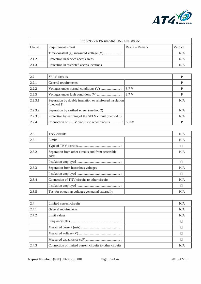
Time-constant (s); measured voltage (V) ................... : N/A
2.1.2 Protection in service access areas N/A
2.1.3 Protection in restricted access locations N/A
2.2 SELV circuits P
2.2.1 General requirements P
2.2.2 Voltages under normal conditions (V) ....................... : 3.7 V P
2.2.3 Voltages under fault conditions (V) ........................... : 3.7 V P
2.2.3.1 Separation by double insulation or reinforced insulation (method 1)
N/A
2.2.3.2 Separation by earthed screen (method 2) N/A
2.2.3.3 Protection by earthing of the SELV circuit (method 3) N/A
2.2.4 Connection of SELV circuits to other circuits ..............: SELV P
2.3 TNV circuits N/A
2.3.1 Limits N/A
Type of TNV circuits ................................................. :
2.3.2 Separation from other circuits and from accessible parts
N/A
Insulation employed ................................................... :
2.3.3 Separation from hazardous voltages N/A
Insulation employed ................................................... :
2.3.4 Connection of TNV circuits to other circuits N/A
Insulation employed ................................................... :
2.3.5 Test for operating voltages generated externally N/A
2.4 Limited current circuits N/A
2.4.1 General requirements N/A
2.4.2 Limit values N/A
Frequency (Hz) ........................................................... :
Measured current (mA) .............................................. :
Measured voltage (V) ................................................. :
Measured capacitance (µF) ........................................ :
2.4.3 Connection of limited current circuits to other circuits N/A

Report Number: (NIE) 39698RSE.001 Page 19 of 47 2013-12-13
IEC 60950-1/ EN 60950-1/UNE EN 60950-1
Clause Requirement – Test Result – Remark Verdict
2.5 Limited power sources P
Inherently limited output P
Impedance limited output N/A
Overcurrent protective device limited output N/A
Regulating network limited output under normal operating and single fault condition
N/A
Regulating network limited output under normal operating conditions and overcurrent protective device limited output under single fault condition
N/A
Output voltage (V), output current (A), apparent power (VA) .......................................................................... :
Battery:
3.8 V, 6.6 A, 25.1VA
USB Connector:
5.3 V, 1.6 A, 8.48VA
Current rating of overcurrent protective device (A)
2.6 Provisions for earthing and bonding N/A
2.6.1 Protective earthing N/A
2.6.2 Functional earthing N/A
2.6.3 Protective earthing and protective bonding conductors N/A
2.6.3.1 General N/A
2.6.3.2 Size of protective earthing conductors N/A
Rated current (A), cross-sectional area (mm2), AWG :
2.6.3.3 Size of protective bonding conductors N/A
Rated current (A), cross-sectional area (mm2), AWG :
2.6.3.4 Resistance (Ω) of earthing conductors and their terminations, test current (A) ...................................... :
N/A
2.6.3.5 Colour of insulation .................................................... : N/A
2.6.4 Terminals N/A
2.6.4.1 General N/A
2.6.4.2 Protective earthing and bonding terminals N/A
Rated current (A), type and nominal thread diameter (mm) ........................................................................... :
2.6.4.3 Separation of the protective earthing conductor from protective bonding conductors
N/A
2.6.5 Integrity of protective earthing N/A
2.6.5.1 Interconnection of equipment N/A

Report Number: (NIE) 39698RSE.001 Page 20 of 47 2013-12-13
IEC 60950-1/ EN 60950-1/UNE EN 60950-1
Clause Requirement – Test Result – Remark Verdict
2.6.5.2 Components in protective earthing conductors and protective bonding conductors
N/A
2.6.5.3 Disconnection of protective earth N/A
2.6.5.4 Parts that can be removed by an operator N/A
2.6.5.5 Parts removed during servicing N/A
2.6.5.6 Corrosion resistance N/A
2.6.5.7 Screws for protective bonding N/A
2.6.5.8 Reliance on telecommunication network or cable distribution system
N/A
2.7 Overcurrent and earth fault protection in primary circuits N/A
2.7.1 Basic requirements The EUT is a Class III equipment
N/A
Instructions when protection relies on building installation
N/A
2.7.2 Faults not covered in 5.3 N/A
2.7.3 Short-circuit backup protection N/A
2.7.4 Number and location of protective devices ............... : N/A
2.7.5 Protection by several devices N/A
2.7.6 Warning to service personnel ..................................... : N/A
2.8 Safety interlocks N/A
2.8.1 General principles N/A
2.8.2 Protection requirements N/A
2.8.3 Inadvertent reactivation N/A
2.8.4 Fail-safe operation N/A
2.8.5 Moving parts N/A
2.8.6 Overriding N/A
2.8.7 Switches and relays N/A
2.8.7.1 Contact gaps (mm) .................................................... : N/A
2.8.7.2 Overload test N/A
2.8.7.3 Endurance test N/A
2.8.7.4 Electric strength test (see appended table 5.2) N/A
2.8.8 Mechanical actuators N/A
2.9 Electrical insulation P
Report Number: (NIE) 39698RSE.001 Page 21 of 47 2013-12-13
IEC 60950-1/ EN 60950-1/UNE EN 60950-1
Clause Requirement – Test Result – Remark Verdict
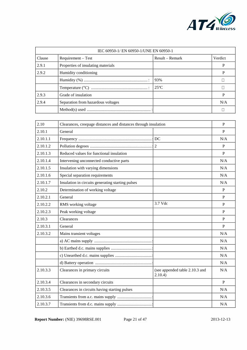
2.9.1 Properties of insulating materials P
2.9.2 Humidity conditioning P
Humidity (%) ............................................................. : 93%
Temperature (°C) ...................................................... : 25ºC
2.9.3 Grade of insulation P
2.9.4 Separation from hazardous voltages N/A
Method(s) used ............................................................. :
2.10 Clearances, creepage distances and distances through insulation P
2.10.1 General P
2.10.1.1 Frequency ...................................................................... : DC N/A
2.10.1.2 Pollution degrees ........................................................... : 2 P
2.10.1.3 Reduced values for functional insulation P
2.10.1.4 Intervening unconnected conductive parts N/A
2.10.1.5 Insulation with varying dimensions N/A
2.10.1.6 Special separation requirements N/A
2.10.1.7 Insulation in circuits generating starting pulses N/A
2.10.2 Determination of working voltage P
2.10.2.1 General P
2.10.2.2 RMS working voltage 3.7 Vdc P
2.10.2.3 Peak working voltage P
2.10.3 Clearances P
2.10.3.1 General P
2.10.3.2 Mains transient voltages N/A
a) AC mains supply ....................................................... : N/A
b) Earthed d.c. mains supplies ....................................... : N/A
c) Unearthed d.c. mains supplies ................................... : N/A
d) Battery operation ...................................................... : N/A
2.10.3.3 Clearances in primary circuits (see appended table 2.10.3 and 2.10.4)
N/A
2.10.3.4 Clearances in secondary circuits P
2.10.3.5 Clearances in circuits having starting pulses N/A
2.10.3.6 Transients from a.c. mains supply ................................. : N/A
2.10.3.7 Transients from d.c. mains supply ................................. : N/A

Report Number: (NIE) 39698RSE.001 Page 22 of 47 2013-12-13
IEC 60950-1/ EN 60950-1/UNE EN 60950-1
Clause Requirement – Test Result – Remark Verdict
2.10.3.8 Transients from telecommunication networks and cable distribution systems ............................................. :
N/A
2.10.3.9 Measurement of transient voltage levels N/A
a) Transients from a mains suplply N/A
For an a.c. mains supply ................................................ : N/A
For a d.c. mains supply .................................................. : N/A
b) Transients from a telecommunication network : N/A
2.10.4 Creepage distances P
2.10.4.1 General P
2.10.4.2 Material group and comparative tracking index P
CTI tests ......................................................................... : IIIa) / IIIb)
2.10.4.3 Minimum creepage distances See appended table 2.10.3 and 2.10.4
P
2.10.5 Solid insulation N/A
2.10.5.1 General N/A
2.10.5.2 Distances through insulation (see appended table 2.10.5) N/A
2.10.5.3 Insulating compound as solid insulation N/A
2.10.5.4 Semiconductor devices N/A
2.10.5.5. Cemented joints (see appended table 2.10.3 and 2.10.4)
N/A
2.10.5.6 Thin sheet material – General N/A
2.10.5.7 Separable thin sheet material N/A
Number of layers (pcs) ................................................... :
2.10.5.8 Non-separable thin sheet material N/A
2.10.5.9 Thin sheet material – standard test procedure N/A
Electric strength test (see appended table 5.2)
2.10.5.10 Thin sheet material – alternative test procedure N/A
Electric strength test
2.10.5.11 Insulation in wound components N/A
2.10.5.12 Wire in wound components N/A
Working voltage ............................................................ : N/A
a) Basic insulation not under stress ............................... : (see appended table 2.10.5) N/A
b) Basic, supplemetary, reinforced insulation ............... : (see appended table 2.10.5) N/A
c) Compliance with Annex U ........................................ : N/A
Two wires in contact inside wound component; angle between 45° and 90° ..................................................... :
N/A

Report Number: (NIE) 39698RSE.001 Page 23 of 47 2013-12-13
IEC 60950-1/ EN 60950-1/UNE EN 60950-1
Clause Requirement – Test Result – Remark Verdict
2.10.5.13 Wire with solvent-based enamel in wound components N/A
Electric strength test
Routine test N/A
2.10.5.14 Additional insulation in wound components N/A
Working voltage ............................................................ : N/A
- Basic insulation not under stress ................................. : N/A
- Supplemetary, reinforced insulation ........................... : N/A
2.10.6 Construction of printed boards P
2.10.6.1 Uncoated printed boards (see appended table 2.10.3 and 2.10.4)
P
2.10.6.2 Coated printed boards N/A
2.10.6.3 Insulation between conductors on the same inner surface of a printed board
(see appended table 2.10.3 and 2.10.4)
N/A
2.10.6.4 Insulation between conductors on different layers of a printed board
N/A
Distance through insulation N/A
Number of insulation layers (pcs) .................................. : N/A
2.10.7 Component external terminations N/A
2.10.8 Tests on coated printed boards and coated components N/A
2.10.8.1 Sample preparation and preliminary inspection N/A
2.10.8.2 Thermal conditioning N/A
2.10.8.3 Electric strength test N/A
2.10.8.4 Abrasion resistance test N/A
2.10.9 Thermal cycling N/A
2.10.10 Test for Pollution Degree 1 environment and insulating compound
N/A
2.10.11 Tests for semiconductor devices and cemented joints N/A
2.10.12 Enclosed and sealed parts N/A
3 WIRING, CONNECTIONS AND SUPPLY P
3.1 General P
3.1.1 Current rating and overcurrent protection P
3.1.2 Protection against mechanical damage N/A
3.1.3 Securing of internal wiring P
3.1.4 Insulation of conductors (see appended table 5.2) P
3.1.5 Beads and ceramic insulators N/A

Report Number: (NIE) 39698RSE.001 Page 24 of 47 2013-12-13
IEC 60950-1/ EN 60950-1/UNE EN 60950-1
Clause Requirement – Test Result – Remark Verdict
3.1.6 Screws for electrical contact pressure N/A
3.1.7 Insulating materials in electrical connections P
3.1.8 Self-tapping and spaced thread screws N/A
3.1.9 Termination of conductors P
10 N pull test P
3.1.10 Sleeving on wiring N/A
3.2 Connection to an a.c. mains supply or a d.c. mains supply N/A
3.2.1 Means of connection ................................................. : The EUT is a Class III equipment supplied by a battery
N/A
3.2.1.1 Connection to an a.c. mains supply N/A
3.2.1.2 Connection to a d.c. mains supply N/A
3.2.2 Multiple supply connections N/A
3.2.3 Permanently connected equipment N/A
Number of conductors, diameter (mm) of cable and conduits ..................................................................... :
3.2.4 Appliance inlets N/A
3.2.5 Power supply cords The equipment does not provide power supply cord
N/A
3.2.5.1 AC power supply cords N/A
Type ........................................................................... :
Rated current (A), cross-sectional area (mm2), AWG:
3.2.5.2 DC power supply cords N/A
3.2.6 Cord anchorages and strain relief N/A
Mass of equipment (kg), pull (N) ............................. :
Longitudinal displacement (mm) ............................... :
3.2.7 Protection against mechanical damage N/A
3.2.8 Cord guards N/A
D (mm); test mass (g) ................................................ :
Radius of curvature of cord (mm) .............................. :
3.2.9 Supply wiring space N/A
3.3 Wiring terminals for connection of external conductors N/A
3.3.1 Wiring terminals N/A
3.3.2 Connection of non-detachable power supply cords N/A

Report Number: (NIE) 39698RSE.001 Page 25 of 47 2013-12-13
IEC 60950-1/ EN 60950-1/UNE EN 60950-1
Clause Requirement – Test Result – Remark Verdict
3.3.3 Screw terminals N/A
3.3.4 Conductor sizes to be connected N/A
Rated current (A), cord/cable type, cross-sectional area (mm2) .......................................................................... :
3.3.5 Wiring terminal sizes N/A
Rated current (A), type and nominal thread diameter (mm) .......................................................................... :
3.3.6 Wiring terminals design N/A
3.3.7 Grouping of wiring terminals N/A
3.3.8 Stranded wire N/A
3.4 Disconnection from the mains supply N/A
3.4.1 General requirement The EUT is a Class III equipment supplied by a battery
N/A
3.4.2 Disconnect devices N/A
3.4.3 Permanently connected equipment N/A
3.4.4 Parts which remain energized N/A
3.4.5 Switches in flexible cords N/A
3.4.6 Single-phase equipment and d.c. equipment N/A
3.4.7 Three-phase equipment N/A
3.4.8 Switches as disconnect devices N/A
3.4.9 Plugs as disconnect devices N/A
3.4.10 Interconnected equipment N/A
3.4.11 Multiple power sources N/A
3.5 Interconnection of equipment P
3.5.1 General requirements P
3.5.2 Types of interconnection circuits ................................ : SELV P
3.5.3 ELV circuits as interconnection circuits N/A
3.5.4 Data ports for additional equipment P
4 PHYSICAL REQUIREMENTS P
4.1 Stability N/A
Angle of 10° Portable equipment N/A
Test: force (N) ..............................................................: N/A

Report Number: (NIE) 39698RSE.001 Page 26 of 47 2013-12-13
IEC 60950-1/ EN 60950-1/UNE EN 60950-1
Clause Requirement – Test Result – Remark Verdict
4.2 Mechanical strength P
4.2.1 General P
4.2.2 Steady force test, 10 N P
4.2.3 Steady force test, 30 N P
4.2.4 Steady force test, 250 N N/A
4.2.5 Impact test SELV supplied equipment N/A
Fall test N/A
Swing test N/A
4.2.6 Drop test P
4.2.7 Stress relief test P
4.2.8 Cathode ray tubes N/A
Picture tube separately certified ................................. : N/A
4.2.9 High pressure lamps N/A
4.2.10 Wall or ceiling mounted equipment; force (N) .......... : N/A
4.3 Design and construction P
4.3.1 Edges and corners P
4.3.2 Handles and manual controls; force (N) ..................... : 30 P
4.3.3 Adjustable controls N/A
4.3.4 Securing of parts P
4.3.5 Connection of plugs and sockets P
4.3.6 Direct plug-in equipment N/A
Dimensions (mm) of mains plug for direct plug-in .. : N/A
Torque and pull test of mains plug for direct plug-in; torque (Nm); pull (N) ................................................. :
N/A
4.3.7 Heating elements in earthed equipment N/A
4.3.8 Batteries See paragraph 5.3 P
4.3.9 Oil and grease N/A
4.3.10 Dust, powders, liquids and gases N/A
4.3.11 Containers for liquids or gases N/A
4.3.12 Flammable liquids ...................................................... : N/A
Quantity of liquid (l)................................................... : N/A
Flash point (°C) .......................................................... : N/A
4.3.13 Radiation; type of radiation ....................................... : N/A

Report Number: (NIE) 39698RSE.001 Page 27 of 47 2013-12-13
IEC 60950-1/ EN 60950-1/UNE EN 60950-1
Clause Requirement – Test Result – Remark Verdict
4.3.13.1 General N/A
4.3.13.2 Ionizing radiation N/A
Measured radiation (pA/kg) ....................................... :
Measured high-voltage (kV) ....................................... :
Measured focus voltage (kV) ..................................... :
CRT markings ............................................................ :
4.3.13.3 Effect of ultraviolet (UV) radiation on materials N/A
4.3.13.4 Human exposure to ultraviolet (UV) radiation .......... : N/A
Part, property, retention after test, flammability classification .............................................................. :
N/A
4.3.13.5 Laser (including LEDs) N/A
Laser class ................................................................. :
4.3.13.6 Other types ................................................................ : N/A
4.4 Protection against hazardous moving parts N/A
4.4.1 General N/A
4.4.2 Protection in operator access areas N/A
4.4.3 Protection in restricted access locations N/A
4.4.4 Protection in service access areas N/A
4.5 Thermal requirements P
4.5.1 Maximum temperatures (see appended table 4.5) P
Normal load condition per Annex L ........................... : N/A
4.5.2 Resistance to abnormal heat N/A
4.6 Openings in enclosures P
4.6.1 Top and side openings P
Dimensions (mm) ...................................................... : No openings
4.6.2 Bottoms of fire enclosures N/A
Construction of the bottom ......................................... : No openings
4.6.3 Doors or covers in fire enclosures N/A
4.6.4 Openings in transportable equipment N/A
4.6.5 Adhesives for constructional purposes N/A
Conditioning temperature (°C)/time (weeks).............. :
Report Number: (NIE) 39698RSE.001 Page 28 of 47 2013-12-13
IEC 60950-1/ EN 60950-1/UNE EN 60950-1
Clause Requirement – Test Result – Remark Verdict
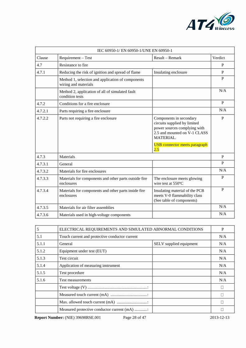
4.7 Resistance to fire P
4.7.1 Reducing the risk of ignition and spread of flame Insulating enclosure P
Method 1, selection and application of components wiring and materials
P
Method 2, application of all of simulated fault condition tests
N/A
4.7.2 Conditions for a fire enclosure P
4.7.2.1 Parts requiring a fire enclosure N/A
4.7.2.2 Parts not requiring a fire enclosure Components in secondary circuits supplied by limited power sources complying with 2.5 and mounted on V-1 CLASS MATERIAL.
USB connector meets paragraph 2.5
P
4.7.3 Materials P
4.7.3.1 General P
4.7.3.2 Materials for fire enclosures N/A
4.7.3.3 Materials for components and other parts outside fire enclosures
The enclosure meets glowing wire test at 550ºC
P
4.7.3.4 Materials for components and other parts inside fire enclosures
Insulating material of the PCB meets V-0 flammability class (See table of components)
P
4.7.3.5 Materials for air filter assemblies N/A
4.7.3.6 Materials used in high-voltage components N/A
5 ELECTRICAL REQUIREMENTS AND SIMULATED ABNORMAL CONDITIONS P
5.1 Touch current and protective conductor current N/A
5.1.1 General SELV supplied equipment N/A
5.1.2 Equipment under test (EUT) N/A
5.1.3 Test circuit N/A
5.1.4 Application of measuring instrument N/A
5.1.5 Test procedure N/A
5.1.6 Test measurements N/A
Test voltage (V) ......................................................... :
Measured touch current (mA) ................................... :
Max. allowed touch current (mA) ............................. :
Measured protective conductor current (mA) ............ :

Report Number: (NIE) 39698RSE.001 Page 29 of 47 2013-12-13
IEC 60950-1/ EN 60950-1/UNE EN 60950-1
Clause Requirement – Test Result – Remark Verdict
Max. allowed protective conductor current (mA) ...... :
5.1.7 Equipment with touch current exceeding 3.5 mA .... : N/A
5.1.8 Touch currents to and from telecommunication networks and cable distribution systems and from telecommunication networks
N/A
5.1.8.1 Limitation of the touch current to a telecommunication network and a cable distribution system
N/A
Test voltage (V) ......................................................... :
Measured touch current (mA) ................................... :
Max. allowed touch current (mA) ............................. :
5.1.8.2 Summation of touch currents from telecommunication networks ..................................................................... :
N/A
5.2 Electric strength P
5.2.1 General (see appended table 5.2) P
5.2.2 Test procedure (see appended table 5.2) P
5.3 Abnormal operating and fault conditions P
5.3.1 Protection against overload and abnormal operation P
5.3.2 Motors (see appended Annex B) N/A
5.3.3 Transformers (see appended Annex C) N/A
5.3.4 Functional insulation .................................................. : The EUT comply the test of the functional insulation short circuited. See table 5.3.
P
5.3.5 Electromechanical components N/A
5.3.6 Audio amplifier devices N/A
5.3.7 Simulation of faults See table 5.3 P
5.3.8 Unattended equipment P
5.3.9 Compliance criteria for abnormal operating and fault conditions
P
6 CONNECTION TO TELECOMMUNICATION NETWORKS N/A
6.1 Protection of telecommunication network service persons, and users of other equipment connected to the network, from hazards in the equipment
N/A
6.1.1 Protection from hazardous voltages N/A
6.1.2 Separation of the telecommunication network from earth N/A
6.1.2.1 Requirements (see appended table 5.2) N/A

Report Number: (NIE) 39698RSE.001 Page 30 of 47 2013-12-13
IEC 60950-1/ EN 60950-1/UNE EN 60950-1
Clause Requirement – Test Result – Remark Verdict
Test voltage (V) ......................................................... :
Current in the test circuit (mA) ................................ :
6.1.2.2 Exclusions .................................................................. : N/A
6.2 Protection of equipment users from overvoltages on telecommunication networks N/A
6.2.1 Separation requirements N/A
6.2.2 Electric strength test procedure N/A
6.2.2.1 Impulse test (see appended table 5.2) N/A
6.2.2.2 Steady-state test (see appended table 5.2) N/A
6.2.2.3 Compliance criteria N/A
6.3 Protection of the telecommunication wiring system from overheating N/A
Max. output current (A) .............................................. :
Current limiting method ............................................. :
7 CONNECTION TO CABLE DISTRIBUTION SYSTEMS N/A
7.1 Protection of cable distribution system service persons, and users of other equipment connected to the system, from hazardous voltages in the equipment
N/A
7.2 Protection of equipment users from overvoltages on the cable distribution system
N/A
7.3 Insulation between primary circuits and cable distribution systems
N/A
7.3.1 General N/A
7.3.2 Voltage surge test (see appended table 5.2) N/A
7.3.3 Impulse test (see appended table 5.2) N/A
A Annex A, TESTS FOR RESISTANCE TO HEAT AND FIRE N/A
A.1 Flammability test for fire enclosures of movable equipment having a total mass exceeding 18 kg, and of stationary equipment (see 4.7.3.2)
N/A
A.1.1 Samples ...................................................................... :
Wall thickness (mm)................................................... :
A.1.2 Conditioning of samples; temperature (°C) ................ : N/A
A.1.3 Mounting of samples .................................................. : N/A
A.1.4 Test flame N/A
A.1.5 Test procedure N/A

Report Number: (NIE) 39698RSE.001 Page 31 of 47 2013-12-13
IEC 60950-1/ EN 60950-1/UNE EN 60950-1
Clause Requirement – Test Result – Remark Verdict
A.1.6 Compliance criteria N/A
Sample 1 burning time (s) .......................................... :
Sample 2 burning time (s) .......................................... :
Sample 3 burning time (s) .......................................... :
A.2 Flammability test for fire enclosures of movable equipment having a total mass not exceeding 18 kg, and for material and components located inside fire enclosures (see 4.7.3.2 and 4.7.3.4)
N/A
A.2.1 Samples, material ....................................................... :
Wall thickness (mm)................................................... :
A.2.2 Conditioning of samples N/A
A.2.3 Mounting of samples N/A
A.2.4 Test flame N/A
A.2.5 Test procedure N/A
A.2.6 Compliance criteria N/A
Sample 1 burning time (s) .......................................... :
Sample 2 burning time (s) .......................................... :
Sample 3 burning time (s) .......................................... :
A.2.7 Alternative test acc. To IEC 60695-2-2, cl. 4, 8 N/A
Sample 1 burning time (s) .......................................... :
Sample 2 burning time (s) .......................................... :
Sample 3 burning time (s) .......................................... :
A.3 Hot flaming oil test (see 4.6.2) N/A
A.3.1 Mounting of samples N/A
A.3.2 Test procedure N/A
A.3.3 Compliance criterion N/A
B Annex B, MOTOR TESTS UNDER ABNORMAL CONDITIONS (see 4.7.2.2 and 5.3.2) N/A
B.1 General requirements N/A
Position ...................................................................... :
Manufacturer ............................................................. :
Type .......................................................................... :
Rated values ............................................................. :
B.2 Test conditions N/A
B.3 Maximum temperatures (see appended table 5.3) N/A
B.4 Running overload test (see appended table 5.3) N/A

Report Number: (NIE) 39698RSE.001 Page 32 of 47 2013-12-13
IEC 60950-1/ EN 60950-1/UNE EN 60950-1
Clause Requirement – Test Result – Remark Verdict
B.5 Locked-rotor overload test N/A
Test duration (days) ................................................... : (see appended table 5.3)
Electric strength test: test voltage (V) ....................... :
B.6 Running overload test for d.c. motors in secondary circuits
N/A
B.7 Locked-rotor overload test for d.c. motors in secondary circuits N/A
B.7.1 Test procedure (see appended table 5.3) N/A
B.7.2 Alternative test procedure; test time (h) ...................... : N/A
B.7.3 Electric strength test (see appended table 5.2) N/A
B.8 Test for motors with capacitors (see appended table 5.3) N/A
B.9 Test for three-phase motors (see appended table 5.3) N/A
B.10 Test for series motors N/A
Operating voltage (V) ................................................ :
C Annex C, TRANSFORMERS (see 1.5.4 and 5.3.3) N/A
Position ...................................................................... :
Manufacturer ............................................................. :
Type .......................................................................... :
Rated values ............................................................. :
Method of protection .................................................. :
C.1 Overload test (see appended table 5.3) N/A
C.2 Insulation (see appended table 5.2) N/A
Protection from displacement of windings ................. : N/A
D Annex D, MEASURING INSTRUMENTS FOR TOUCH-CURRENT TESTS N/A
D.1 Measuring instrument N/A
D.2 Alternative measuring instrument N/A
E Annex E, TEMPERATURE RISE OF A WINDING N/A
F Annex F, MEASUREMENT OF CLEARANCES AND CREEPAGE DISTANCES (see 2.10)
P
G Annex G, ALTERNATIVE METHOD FOR DETERMINING MINIMUM CLEARANCES
N/A
Report Number: (NIE) 39698RSE.001 Page 33 of 47 2013-12-13
IEC 60950-1/ EN 60950-1/UNE EN 60950-1
Clause Requirement – Test Result – Remark Verdict
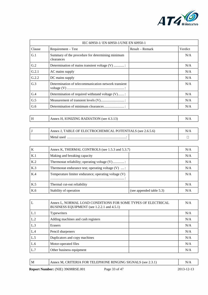
G.1 Summary of the procedure for determining minimum clearances
N/A
G.2 Determination of mains transient voltage (V) ............ : N/A
G.2.1 AC mains supply N/A
G.2.2 DC mains supply N/A
G.3 Determination of telecommunication network transient voltage (V) ................................................................. :
N/A
G.4 Determination of required withstand voltage (V) ....... : N/A
G.5 Measurement of transient levels (V)........................... : N/A
G.6 Determination of minimum clearances ....................... : N/A
H Annex H, IONIZING RADIATION (see 4.3.13) N/A
J Annex J, TABLE OF ELECTROCHEMICAL POTENTIALS (see 2.6.5.6) N/A
Metal used ...................................................................:
K Annex K, THERMAL CONTROLS (see 1.5.3 and 5.3.7) N/A
K.1 Making and breaking capacity N/A
K.2 Thermostat reliability; operating voltage (V) ............. : N/A
K.3 Thermostat endurance test; operating voltage (V) .... : N/A
K.4 Temperature limiter endurance; operating voltage (V) .................................................................................... :
N/A
K.5 Thermal cut-out reliability N/A
K.6 Stability of operation (see appended table 5.3) N/A
L Annex L, NORMAL LOAD CONDITIONS FOR SOME TYPES OF ELECTRICAL BUSINESS EQUIPMENT (see 1.2.2.1 and 4.5.1)
N/A
L.1 Typewriters N/A
L.2 Adding machines and cash registers N/A
L.3 Erasers N/A
L.4 Pencil sharpeners N/A
L.5 Duplicators and copy machines N/A
L.6 Motor-operated files N/A
L.7 Other business equipment N/A
M Annex M, CRITERIA FOR TELEPHONE RINGING SIGNALS (see 2.3.1) N/A

Report Number: (NIE) 39698RSE.001 Page 34 of 47 2013-12-13
IEC 60950-1/ EN 60950-1/UNE EN 60950-1
Clause Requirement – Test Result – Remark Verdict
M.1 Introduction N/A
M.2 Method A N/A
M.3 Method B N/A
M.3.1 Ringing signal N/A
M.3.1.1 Frequency (Hz) .......................................................... :
M.3.1.2 Voltage (V) ............................................................... :
M.3.1.3 Cadence; time (s), voltage (V) ................................... :
M.3.1.4 Single fault current (mA) ............................................ :
M.3.2 Tripping device and monitoring voltage .................... : N/A
M.3.2.1 Conditions for use of a tripping device or a monitoring voltage
N/A
M.3.2.2 Tripping device N/A
M.3.2.3 Monitoring voltage (V) .............................................. : N/A
N Annex N, IMPULSE TEST GENERATORS (see 2.10.3.4, 6.2.2.1, 7.3.2 and clause G.5) N/A
N.1 ITU-T impulse test generators N/A
N.2 IEC 60065 impulse test generator N/A
P Annex P, NORMATIVE REFERENCES P
Q Annex Q, BIBLIOGRAPHY P
R Annex R, EXAMPLES OF REQUIREMENTS FOR QUALITY CONTROL PROGRAMMES
N/A
R.1 Minimum separation distances for unpopulated coated printed boards (see 2.10.6)
N/A
R.2 Reduced clearances (see 2.10.3) N/A
S Annex S, PROCEDURE FOR IMPULSE TESTING (see 6.2.2.3) N/A
S.1 Test equipment N/A
S.2 Test procedure N/A
S.3 Examples of waveforms during impulse testing N/A
T Annex T, GUIDANCE ON PROTECTION AGAINST INGRESS OF WATER (see 1.1.2) N/A
See separate test report

Report Number: (NIE) 39698RSE.001 Page 35 of 47 2013-12-13
IEC 60950-1/ EN 60950-1/UNE EN 60950-1
Clause Requirement – Test Result – Remark Verdict
U Annex U, INSULATED WINDING WIRES FOR USE WITHOUT INTERLEAVED INSULATION (see 2.10.5.4)
N/A
See separate test report
ZA Annex ZA, Other international standards mentioned in this standard with the reference of the corresponding European standard (Normative)
N/A
ZB Annex ZB, Especial national conditions (Normative) N/A
ZC Annex ZC, Type A deviations (Informative) N/A
Zx Protection against excessive sound pressure from personal music players
N/A
Annex Zx, Significance of LAeq,t in EN 50332-1 and additional information (Informative)
N/A
Report Number: (NIE) 39698RSE.001 Page 36 of 47 2013-12-13
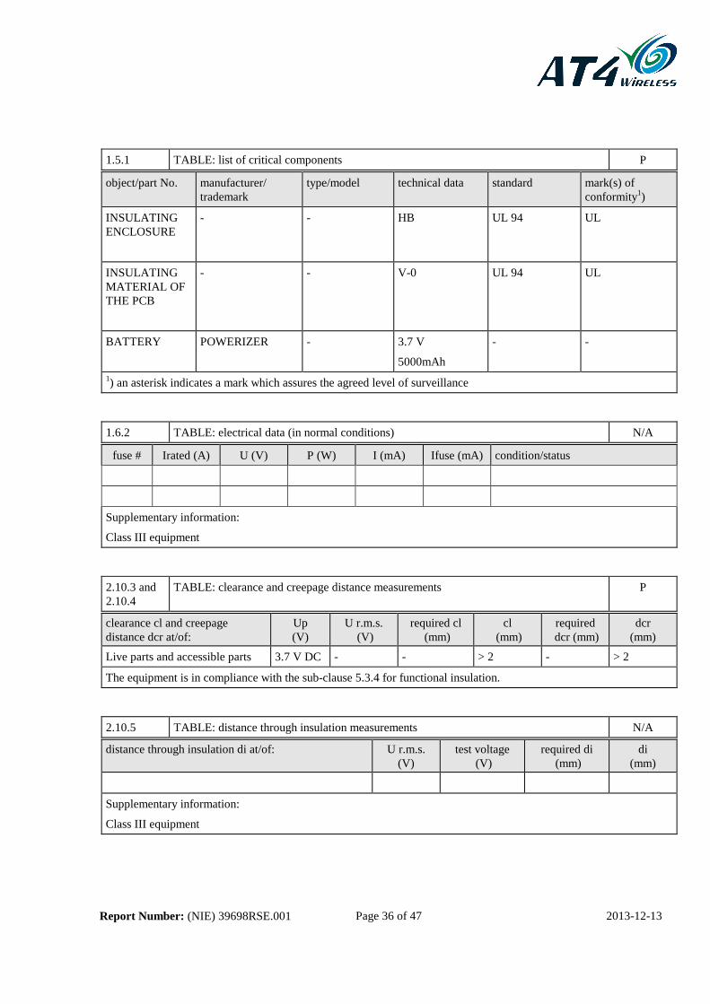
1.5.1 TABLE: list of critical components P object/part No. manufacturer/
trademark type/model technical data standard mark(s) of
conformity1)
INSULATING ENCLOSURE
- - HB UL 94 UL
INSULATING MATERIAL OF THE PCB
- - V-0 UL 94 UL
BATTERY POWERIZER - 3.7 V
5000mAh
- -
1) an asterisk indicates a mark which assures the agreed level of surveillance
1.6.2 TABLE: electrical data (in normal conditions) N/A
fuse # Irated (A) U (V) P (W) I (mA) Ifuse (mA) condition/status
Supplementary information:
Class III equipment
2.10.3 and 2.10.4
TABLE: clearance and creepage distance measurements P
clearance cl and creepage distance dcr at/of:
Up (V)
U r.m.s. (V)
required cl (mm)
cl (mm)
required dcr (mm)
dcr (mm)
Live parts and accessible parts 3.7 V DC - - > 2 - > 2
The equipment is in compliance with the sub-clause 5.3.4 for functional insulation.
2.10.5 TABLE: distance through insulation measurements N/A distance through insulation di at/of: U r.m.s.
(V) test voltage
(V) required di
(mm) di
(mm)
Supplementary information:
Class III equipment

Report Number: (NIE) 39698RSE.001 Page 37 of 47 2013-12-13
4.5 TABLE: maximum temperatures P
test voltage (V) ..................................... : 4.4 V DC (3.7 VDC + 20%)
3.1 V DC (3.7 VDC – 15%)
tamb1 (°C) ................................................ : 22.9 23.1
tamb2 (°C) ................................................ : 23.1 23.3 maximum temperature T of part/at:: T (°C) allowed
Tmax (°C)
Insulating enclosure 24.2± 2.1ºC 24.4± 2.1ºC 95
Joystik connector 24.3 ± 2.1ºC 24.6 ± 2.1ºC 85
Power button 23.7 ± 2.1ºC 23.8 ± 2.1ºC 95
Lateral buttons 23.8 ± 2.1ºC 24.0 ± 2.1ºC 95
PCB 25.5 ± 2.1ºC 25.7 ± 2.1ºC 95
Battery 26.4 ± 2.1ºC 27.1 ± 2.1ºC - temperature T of winding: R1 (Ω) R2 (Ω) T (°C) allowed
Tmax (°C) insulation
class
N/A
Supplementary information:
Battery supplied equipment.
4.5.2 TABLE: ball pressure test of thermoplastic parts N/A
allowed impression diameter (mm) ............................. : ≤ 2 mm part test temperature (°C) impression diameter
(mm)
Supplementary information: The EUT operates at SELV
4.7 TABLE: resistance to fire P
part manufacturer of material type of material thickness (mm)
flammability class
PCB --- FR4 1.6 V-0
Insulating enclosure
--- Thermoplastic 1.2 Glow Wire Test at 550ºC
Supplementary information:

Report Number: (NIE) 39698RSE.001 Page 38 of 47 2013-12-13
5.2 TABLE: electric strength tests, impulse tests and voltage surge tests P test voltage applied between: test voltage (V) breakdown
Yes / No
Live parts and accessible parts 500 V No
supplementary information
Test voltage a.c. / d.c.
5.3 TABLE: fault condition tests P
ambient temperature (°C) ........................................... : 23.2
model/type of power supply ........................................ : N/A
manufacturer of power supply .................................... : N/A
rated markings of power supply .................................. : N/A component No.
fault
test voltage (V)
test time fuse No.
fuse current (A)
result
Battery Short circuit 3.1 V DC 1 h - - Inherent protection works. The temperatures measured are in compliance with the standard
Battery Change of polarity
3.1 V DC 1h - - The battery connector does not allow to change the polarity
Battery Overload 3.1 V DC 7h - - Inherent protection works. The temperatures measured are in compliance with the standard
EUT Short circuit of the resistance near the battery connector
3.1 V DC 1h - - Inherent protection works. The temperatures measured are in compliance with the standard
EUT Short circuit of the Joystick connector
3.1 V DC 1h - - The temperatures measured are in compliance with the standard
supplementary information

Report Number: (NIE) 39698RSE.001 Page 39 of 47 2013-12-13
A.6.5 TABLE: flammability test for classifying materials V-0, V-1 or V-2 P sample No. / ref.
afterflame time (s) t1 or t2 afterflame + afterglow (s) after 2nd flame application t2 + t3
1/A 1 2
2/A 2 3
3/A 2 2
4/A 2 3
5/A 1 3
6/B 2 2
7/B 2 3
8/B 3 3
9/B 1 2
10/B 2 1
Supplementary information: Insulating material of the PCB tested.
Total afterflame time (s) for any condition set t1 + t2 for five (5) specimens:
Conditioning “A” designates 7 days at 70 °C ± 1 °C followed by 4 h minimum in calcium chloride desiccator.
Conditioning “B” designates 48 h at 23 °C ± 2 °C and relative humidity between 45 % and 55 %.
A.6.6 TABLE: flammability re-test for classifying materials V-0, V-1 or V-2 N/A sample No. afterflame time (s) t1 or t2 afterflame + afterglow (s) after 2nd flame application
t2 + t3
11
12
13
14
15 supplementary information:
Total afterflame time (s) for any condition set t1 + t2 for five (5) specimens:

Report Number: (NIE) 39698RSE.001 Page 40 of 47 2013-12-13
A.7.4, A.7.5, A.7.6 and A.7.7
TABLE: flammability test for classifying foam materials HF-1, HF-2 or HBF N/A
sample No. / ref.
flame time (s) glow time (s) flaming/glowing distance from the end (mm)
comment (for A.7.7 burning rate
mm/min)
1/A
2/A
3/A
4/A
5/A
6/B
7/B
8/B
9/B
10/B supplementary information:
Conditioning “A” designates 7 days at 70 °C ± 1 °C followed by 4 h minimum in calcium chloride desiccator.
Conditioning “B” designates 48 h at 23 °C ± 2 °C and relative humidity between 45 % and 55 %.
A.7.8 TABLE: flammability re-test for classifying foam materials HF-1 or HF-2 N/A sample No. flame time (s) glow time (s) flaming/glowing distance
from the end (mm) comment
11
12
13
14
15
supplementary information:

Report Number: (NIE) 39698RSE.001 Page 41 of 47 2013-12-13
A.7.9 TABLE: flammability re-test for classifying foam materials HBF N/A sample No. flame time (s) glow time (s) flaming/glowing distance
from the end (mm) comment
(for A.7.7 burning rate mm/min)
11
12
13
14
15
supplementary information:
A.8.5 TABLE: flammability test for classifying materials HB N/A sample No. flaming/glowing rate
mm/min flaming/glowing distance from reference mark (mm)
1
2
3
supplementary information:
A.8.6 TABLE: flammability re-test for classifying materials HB N/A sample No. flaming/glowing rate
mm/min flaming/glowing distance from reference mark (mm)
4
5
6
supplementary information:

Report Number: (NIE) 39698RSE.001 Page 42 of 47 2013-12-13
A.9.6 TABLE: flammability test for classifying materials 5V N/A sample test bars test plaques
No./ref. flaming + glowing time (s)
burning distance (mm)
position flaming + glowing time (s)
burning distance (mm)
1/A A
2/A B
3/A C
4/A D
5/A
6/B A
7/B B
8/B C
9/B D
10/B
supplementary information:
Conditioning “A” designates 7 days at 70 °C ± 1 °C followed by 4 h minimum in calcium chloride desiccator.
Conditioning “B” designates 48 h at 23 °C ± 2 °C and relative humidity between 45 % and 55 %.
A.9.7 TABLE: flammability re-test for classifying materials 5V N/A sample No. test bars test plaques
flaming + glowing time (s)
burning distance (mm)
position flaming + glowing time (s)
burning distance (mm)
11 A
12 B
13 C
14 D
15
supplementary information:

Report Number: (NIE) 39698RSE.001 Page 43 of 47 2013-12-13
APPENDIX B: Photographs
Report Number: (NIE) 39698RSE.001 Page 44 of 47 2013-12-13
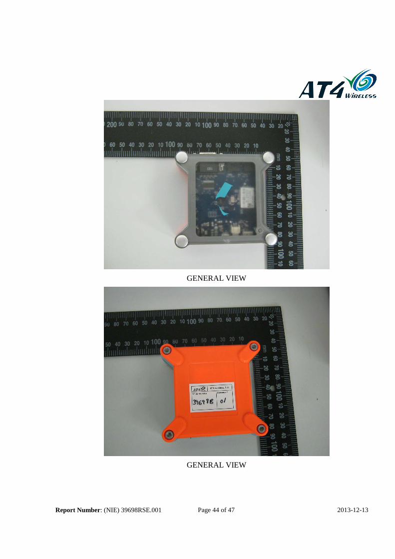
GENERAL VIEW
GENERAL VIEW

Report Number: (NIE) 39698RSE.001 Page 45 of 47 2013-12-13
GENERAL VIEW
GENERAL VIEW

Report Number: (NIE) 39698RSE.001 Page 46 of 47 2013-12-13
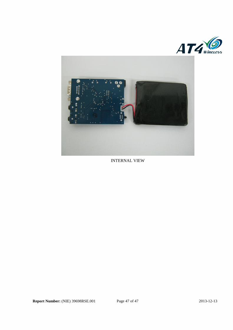
INTERNAL VIEW
Report Number: (NIE) 39698RSE.001 Page 47 of 47 2013-12-13
INTERNAL VIEW