ata 61-2 - avia propeller · ata 61-20-99 (e-1900) operation and ... governor is a vital component...
TRANSCRIPT

ATA 61-20-99 (E-1900)
Operation and Installation Manual
Synchrophasing System for Turboprop and Piston Engines
APS-W( )-( )
The technical content of this document is approved under authority of DOA No. EASA.21J.072.
Issue 3: April 22nd
, 2015

ATA 61-20-….
www.aviapropeller.com
Warning
People who fly should recognize that various types of risks are involved; and they should take all precautions to minimize them, since they can not be eliminated entirely. The governor is a vital component of the aircraft. A mechanical failure could cause a forced landing. Governors are subject to constant vibration stresses from the engine. Before a governor is certified as being safe to operate on an airplane engine, an adequate margin of safety must be demonstrated. Even though every precaution is taken in the design and manufacture of a governor, history has revealed rare instances of failures, particularly of the fatigue type. It is essential that the governor be properly maintained according to the recommended service procedures and a close watch be exercised to detect impending problems before they become serious. Unusual operation characteristics should be investigated and repaired as it could be a warning that something serious is wrong. The governor is among the most reliable components of your airplane. It therefore deserves the care and maintenance called for in this Manual. Please give it your attention, especially the section dealing with Inspections and Checks. Thank you for choosing an Avia Propeller governor. Properly maintained it will give you many years of reliable service. Your Avia Propeller technical support team Page 0-1 2012-08-31

ATA 61-20-….
www.aviapropeller.com
Table of contents Page Table of Contents (Overview) 1
List of inserted revisions 2
List of effective pages 2
1. General 3
2. Model Designation 3
3. Performance Data 4
4. Design and Operation Information 5
5. Installation Instruction 7
6. Inspections 8
7. Troubleshooting 8
8. Shipping and Storage 9
9. System installation record 10
Page 1 2012-08-31

ATA 61-20-….
www.aviapropeller.com
List of Inserted Revisions
No.
Date of Issue
Pages
Remark
1
2012-08-31
all
Initial Issue
2
2014-03-16
2, 4, 5, 6, 7, 10
New Synchrophaser introduced
3
2015-04-22
2, 5
Update of Fig. 3 (phase selector removed)
4
5
6
List of Effective Pages
Page
Date of Issue
0-1 2012-08-31 1 2012-08-31 2 2015-04-22 3 2012-08-31 4 2014-03-16 5 2015-04-22 6 2014-03-16 7 2014-03-16 8 2012-08-31 9 2012-08-31 10 2014-03-16
Issue 3 Page 2 2015-04-22

ATA 61-20-….
www.aviapropeller.com
1.0 GENERAL
The APS-W( )-( ) system consists of synchrophaser controller, synchrophasing propgovernor accessories (synchrophasing coils, speed sensors), wiring harness and cockpit instrumentation. The system continuously monitors and maintains propeller synchronization and phasing, working in conjunction with Avia Propeller P-8( ) and P-W( ) series synchrophasing propgovernors.
1.1 Statement of purpose
This manual provides data required to insure the satisfactory operation, maintenance and repair of the Avia Propeller APS-W( )-( ) synchrophasing system. This manual must be used in conjunction with the applicable basic Aircraft Maintenance/Service Manual.
2.0 MODEL DESIGNATION APS - W 0 - 1 1 2 3 4 Legend: 1 APS = Avia Propeller Synchrophasing System 2 W = for GE turboprop engines A = for Austro Engine L = for other piston engines 3 0 = basic arrangement 4 = Application Number, propgovernor used etc. S/No. 11 S 003 a b c a = Year of Manufacture b = Synchrophasing System c = Consecutive Number Page 3 2012-08-31

ATA 61-20-….
www.aviapropeller.com
3.0 PERFORMANCE DATA Supply voltage: 9 to 36 VDC Normal current draw: 3 A at 14 VDC Normal operating frequency: 25 to 60 Hz (1500 to 3600 rpm) Nominal input pulse amplitude: 1,5 to 1,75 Volts, peak 3.1 Dimensions Fig. 1 – Propeller governor with synchrophasing feature for GE H-80 engine
Fig. 2 – Synchrophasing control unit A213796
Issue 2 Page 4 2014-03-16
ATA 61-20-….
www.aviapropeller.com
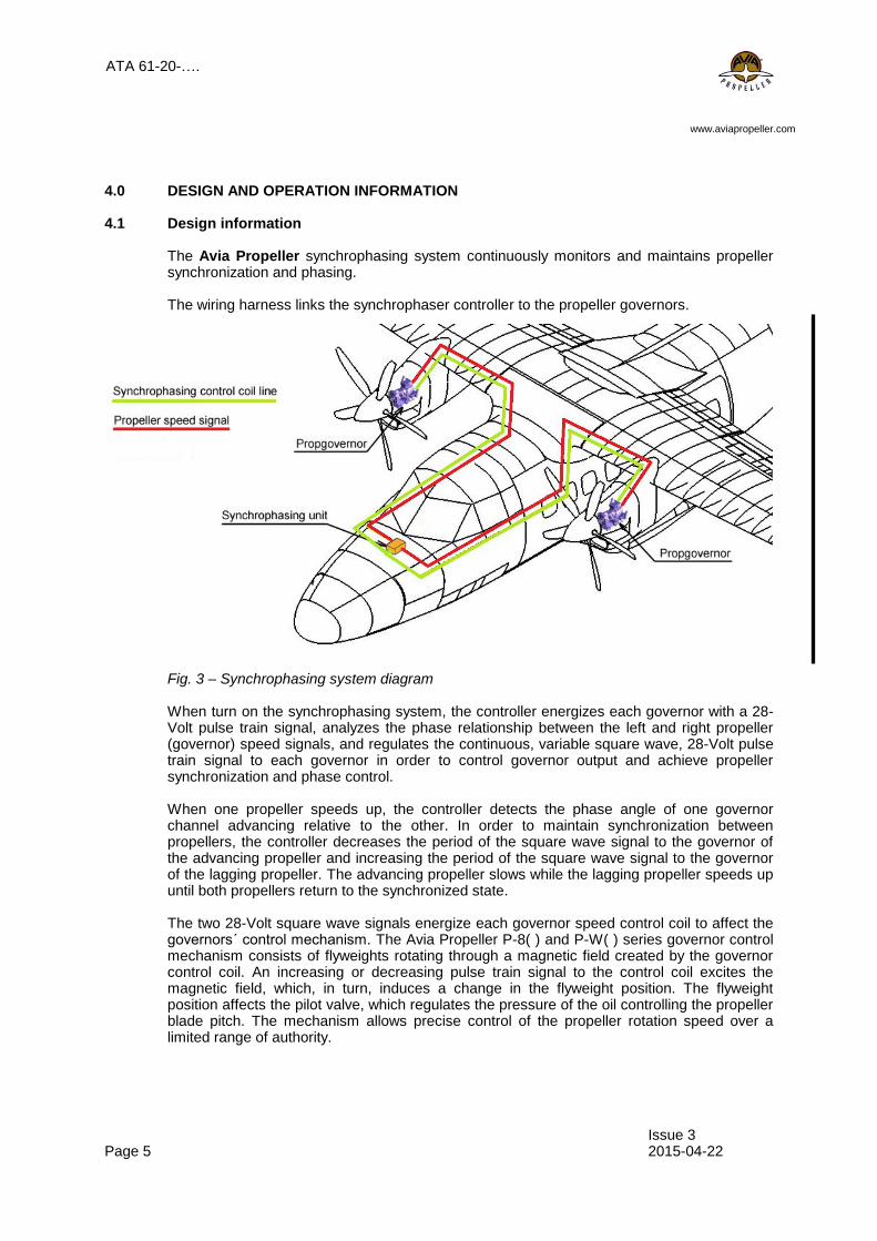
4.0 DESIGN AND OPERATION INFORMATION 4.1 Design information The Avia Propeller synchrophasing system continuously monitors and maintains propeller
synchronization and phasing.
The wiring harness links the synchrophaser controller to the propeller governors.
Fig. 3 – Synchrophasing system diagram When turn on the synchrophasing system, the controller energizes each governor with a 28-Volt pulse train signal, analyzes the phase relationship between the left and right propeller (governor) speed signals, and regulates the continuous, variable square wave, 28-Volt pulse train signal to each governor in order to control governor output and achieve propeller synchronization and phase control. When one propeller speeds up, the controller detects the phase angle of one governor channel advancing relative to the other. In order to maintain synchronization between propellers, the controller decreases the period of the square wave signal to the governor of the advancing propeller and increasing the period of the square wave signal to the governor of the lagging propeller. The advancing propeller slows while the lagging propeller speeds up until both propellers return to the synchronized state. The two 28-Volt square wave signals energize each governor speed control coil to affect the governors´ control mechanism. The Avia Propeller P-8( ) and P-W( ) series governor control mechanism consists of flyweights rotating through a magnetic field created by the governor control coil. An increasing or decreasing pulse train signal to the control coil excites the magnetic field, which, in turn, induces a change in the flyweight position. The flyweight position affects the pilot valve, which regulates the pressure of the oil controlling the propeller blade pitch. The mechanism allows precise control of the propeller rotation speed over a limited range of authority.
Issue 3 Page 5 2015-04-22
ATA 61-20-….
www.aviapropeller.com
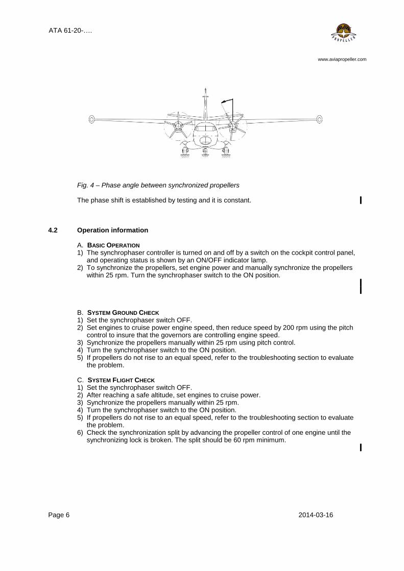
Fig. 4 – Phase angle between synchronized propellers The phase shift is established by testing and it is constant.
4.2 Operation information
A. BASIC OPERATION 1) The synchrophaser controller is turned on and off by a switch on the cockpit control panel,
and operating status is shown by an ON/OFF indicator lamp. 2) To synchronize the propellers, set engine power and manually synchronize the propellers
within 25 rpm. Turn the synchrophaser switch to the ON position. B. SYSTEM GROUND CHECK 1) Set the synchrophaser switch OFF. 2) Set engines to cruise power engine speed, then reduce speed by 200 rpm using the pitch
control to insure that the governors are controlling engine speed. 3) Synchronize the propellers manually within 25 rpm using pitch control. 4) Turn the synchrophaser switch to the ON position. 5) If propellers do not rise to an equal speed, refer to the troubleshooting section to evaluate
the problem. C. SYSTEM FLIGHT CHECK 1) Set the synchrophaser switch OFF. 2) After reaching a safe altitude, set engines to cruise power. 3) Synchronize the propellers manually within 25 rpm. 4) Turn the synchrophaser switch to the ON position. 5) If propellers do not rise to an equal speed, refer to the troubleshooting section to evaluate
the problem. 6) Check the synchronization split by advancing the propeller control of one engine until the
synchronizing lock is broken. The split should be 60 rpm minimum.
Page 6 2014-03-16

ATA 61-20-….
www.aviapropeller.com
5.0 INSTALLATION INSTRUCTION
The propeller governors are installed according to respective Installation Manual. The synchrophaser box is mounted for example under the aircraft´s glove box located on the copilot´s side of the cockpit and has a plug receptacle to connect wiring harness – see figure below.
Fig. 5 – Synchrophaser installation The wiring harness links the synchrophaser controller to the propeller governors. Figure 6 shows electrical interconnections between all synchrophasing components. Fig. 6 – Synchrophasing Wiring Diagram for A213796
Page 7 2014-03-16

ATA 61-20-….
www.aviapropeller.com
6.0 INSPECTIONS
The propeller governors are inspected according to appropriate governor´s manuals. The synchrophaser controller does not require periodic maintenance, and there is no component overhaul required for controller. The ensuing maintenance instructions should be followed to correct a malfunction of the synchrophaser system. Refer to the troubleshooting section for guidance.
System Wiring Check 1) Turn Master Switch OFF, pull synchrophaser circuit breaker OUT, and disconnect wiring
harness from synchrophaser controller. 2) Test wiring by connecting an ohmmeter to the wiring harness plug connector pins
according to the chart and plug illustration shown in Fig. 6 and Table 1. To check: Required reading: Primary power (Master switch ON, circuit breaker SET)
Supply voltage 28 VDC
First governor speed pick-up 50 to 70 Ω Second governor speed pick-up 50 to 70 Ω First governor control coil 28 to 37 Ω Second governor control coil 28 to 37 Ω Phasing control 0 to 50 kΩ, variable
Table 1. – Synchrophaser System Wiring Check 3) If faults are discovered, use the information in the chart in Fig. 6 to correct the problem.
7. TROUBLESHOOTING A. If the synchrophaser system initially works, but occasionally loses synchronization, or the
engine speed surges or hunts, or the system is marginally stable and does not achieve the specified synchronization split, the governor may not be calibrated correctly. Check the governor rpm gain by the Avia Propeller governor test and adjustment procedures.
B. If the synchrophaser circuit breaker trips, there is a short in the power lead. Check the
wiring by System Wiring Check procedures.
C. If the synchrophaser system is inoperative:
- Check for broken or chafed wires in the synchrophaser wiring harness from the governor to the engine firewall.
- Check the synchrophaser wiring harness plug for loose wires, and check the control box plug receptacle for loose, bent, or damaged pins.
- Check to see the system is getting power by following the System Wiring Check procedures.
- Check the governor speed pick-up and control coil for each engine by the Avia Propeller governor test and adjustment procedures.
- Check the phasing control by following the System wiring Check procedures.
D. After completion of troubleshooting procedures, perform an operational check of the synchrophaser system.
E. If the system remains inoperative after satisfactorily completing all troubleshooting
procedures, replace the synchrophaser box.
Issue 1 Page 8 2012-08-31

ATA 61-20-….
www.aviapropeller.com
8.0 SHIPPING AND STORAGE Propeller governor conservation Inner conservation is automatically done by engine oil. Attach cover cap.
After installing the governor the conservation is done together with engine in accordance with the instruction of the engine manufacturer.
Outside conservation isn’t required.
Pack the governor in two layers of wax-cloth and put it in a plastic bag. The plastic bag should be vacuumed and after that welded.
Make a note in the governor’s installation record. Deconservation isn’t needed. Storage Instruments have to be packed in carton box with accessory documentation. Store instruments in temperature from +10°C (+50°F) to +30°C (+86 °F) and relative humidity
from 40 % to 80 %. Keep stock room free of gases with deleterious effect. Page 8 2012-08-31

ATA 61-20-….
www.aviapropeller.com
9. SYSTEM INSTALLATION RECORD Left propgovernor – P/N: P-…………… S/N: ………………………… Right propgovernor – P/N: P-…………… S/N: ………………………… Synchrophaser – P/N: A213796 S/N: …………………………
Date
installed
Notes Authorized
Signature
Date
Removed
Page 10 2014-03-16