atlas bp8000/bp9000 installation & operation...
TRANSCRIPT

CONTENTS
Product Features and Specifications ..............................................1
Installation Requirement ............................................................ 4
Steps of Installation ………………………………………………..……………………………5
Exploded View .........................................................................19
Test Run .................................................................................23
Operation Instruction ................................................................26
Maintenance ........................................................................... 26
Trouble Shooting ..................................................................... 27
Parts List................................................................................ 28

1
I. PRODUCT FEATURES AND SPECIFICATIONS
FLOOR PLATE CHAIN-DRIVE MODEL FEATURES
Model BP8000 (See Fig. 1)
· Compact design
· Dual hydraulic cylinders, designed and made on ANSI standards, utilizing NOK oil
seal for cylinder
· Self- lubricating UHMW Polyethylene sliders and bronze bush
· Single-point safety release and dual safety design
Fig. 1
MODEL BP8000 SPECIFICATIONS
Model Style Lifting Capacity
Lifting Time Lifting Height Overall
Height Overall Width
Width Between
Posts
Minimum Pad Height
for screw adapters
Minimum Pad Height for stackable
adapter Motor
BP8000 Floor plate
Chain-drive
4.0 T
9,000 lbs 45 Sec
1825-1905 mm
72” – 75”
2738 mm
107 3/4”
3350 mm
132”
2780 mm
109 1/2”
100 mm
4”
80 mm
3 1/8” 2.0/3.0 HP

2
FLOOR PLATE CHAIN-DRIVE TWO POST LIFT
Model BP9000 (See Fig. 2)
· Compact design
· Dual hydraulic cylinders, designed and made on ANSI standards, utilizing NOK oil seal for
cylinder
· Self- lubricating UHMW Polyethylene sliders and bronze bush
· Single-point safety release and dual safety design
· Super-Symmetric (2 in 1) arms design, Stackable adapters 1.5”, 3”, 6” as standard
Fig. 2
MODEL BP9000 SPECIFICATIONS
Model Style Lifting Capacity
Lifting Time Lifting Height Overall
Height Overall Width
Width Between
Posts
Minimum Pad Height for stackable
adapter
Minimum Pad Height
for screw adapters
Motor
BP9000 Floor plate
Chain-drive
4.0 T
9,000 lbs 49 S
1930-2200 mm
76” – 86 5/8”
2837 mm
111 3/4”
3458 mm
136 1/8”
2850 mm
112 1/4”
105 mm
3 1/8
100 mm
4” 2.0/3.0 HP

3
Arm Swings View
Fig. 3
Model BP8000
Fig. 4
Model BP9000

4
�. INSTALLATION REQUIREMENT
A. TOOLS REQUIRED
Rotary Hammer Drill (19mm/3/4”)
Hammer
4 Foot Level
Crescent Wrench (12mm)
Ratchet With Socket (30mm)
Metric Wrench set
Carpenter’s Chalk
Screw Drivers
Tape Measure (25 Foot)
Pliers
Allen Head Wrench (6#)
Vise Grips
(10#, 13#, 14#, 15#, 17#, 19#, 24#, 27#)
Fig. 5
5
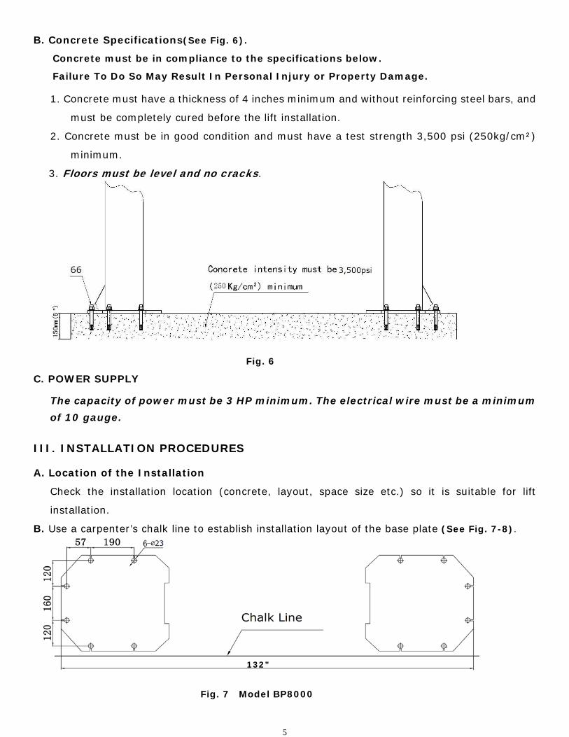
B. Concrete Specifications(See Fig. 6).
Concrete must be in compliance to the specifications below.
Failure To Do So May Result In Personal Injury or Property Damage.
1. Concrete must have a thickness of 4 inches minimum and without reinforcing steel bars, and
must be completely cured before the lift installation.
2. Concrete must be in good condition and must have a test strength 3,500 psi (250kg/cm²)
minimum.
3. Floors must be level and no cracks.
Fig. 6
C. POWER SUPPLY
The capacity of power must be 3 HP minimum. The electrical wire must be a minimum of 10 gauge.
III. INSTALLATION PROCEDURES
A. Location of the Installation
Check the installation location (concrete, layout, space size etc.) so it is suitable for lift
installation.
B. Use a carpenter’s chalk line to establish installation layout of the base plate (See Fig. 7-8).
Fig. 7 Model BP8000
132”

6
Fig. 8 Model BP9000
C. Check the Parts Before Assembly.
1. Packaged lift and Hydraulic Power Unit (See Fig. 9).
Fig. 9
2. Move aside the lift with fork lift or hoist, and open the outer packing carefully
(See Fig. 10).
Fig. 10
Shipment Parts list Floor cover Parts box Serial No.
136 3/8”

7
3. Take out the parts from upper and inside of the column, then take out the parts box, and check
the parts according to the shipment parts list (See Fig. 11 & Fig. 12). WARNING: Truck
Adapters are located inside of the columns.
Fig. 11 Model BP8000
Fig. 12 Model BP9000
4. Loosen the screws on the upper package stand, take off the upper column and remove the
package stand (See Fig. 13).
Fig. 13

8
5. Open the parts box and check the parts according to parts box list (See Fig. 14 & Fig.15).
Model BP8000
Fig. 14
Model BP9000
Fig. 15
6. Check the parts bag according to parts bag list (See Fig. 16 & Fig.17).
Model BP8000
Fig. 16
Model BP9000
Fig. 17

9
D. Position Power side Post Lay down two posts on the installation site parallel, position the Power side post according to the
actual installation environment.
(See Fig. 18 & Fig. 19).
Fig. 18 Model BP8000
Fig. 19 Model BP9000
Car-in direction
Power side post
Offside post
Assemble Top plate using M10*35 Hex Bolt with Nut and Spring Washer
Car in Direction
Power side post
Offside post
Assemble Top plate using M10*35 Hex Bolt with Nut and Spring Washer
10
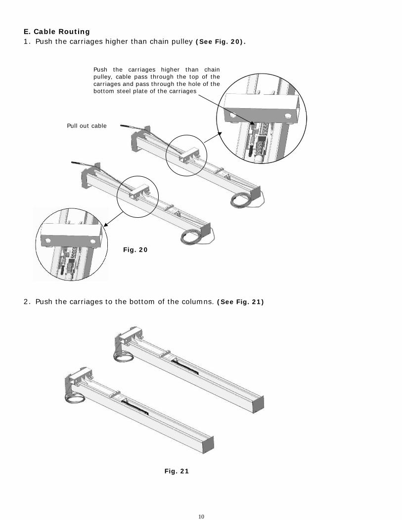
E. Cable Routing 1.Push the carriages higher than chain pulley (See Fig. 20).
2.Push the carriages to the bottom of the columns. (See Fig. 21)
Fig. 20
Fig. 21
Push the carriages higher than chain pulley, cable pass through the top of the carriages and pass through the hole of the bottom steel plate of the carriages
Pull out cable

11
F. Position posts (See Fig. 22)
Check the posts plumb with level bar, and adjusting with the shims if the columns are not
vertical.
G. Fix Anchor Bolts
1. Prepare the anchor bolts. (See Fig. 23)
Fig. 23
2. Use a hammer drill with a ¾” (19mm) masonry bit and drill all the anchor holes. Install the
anchor bolts with a hammer. Tighten the Anchor Bolts between 85 and 110 foot pounds (See Fig.
24).
Fig. 24
Fig. 22
Model BP8000: Appx. 109 ½” Model BP9000: Aprx 112 ¼”
Model BP8000: 132” Model BP9000: 136 3/8”
Spring washer Washer Nut
Work Smart not Hard
No need to measure. Use the base plate as a distance gauge. Before drilling the anchor holes, position the columns up to each end of the base plate. Double check that the
columns are positioned on the chalk line.

12
H. Lift the carriages up by hand and rest them on the first set of locks
(See Fig. 25).
I. Install Cables (See Fig. 26)
Fig. 25
Fig. 26
The fitting of cable passes through the hole on the carriages and is screwed with the two cable nuts.

13
J. Oil Hose Assembly (See Fig. 27).
Fig. 27
K. Install Hydraulic Power Unit and Oil Hose Assembly (See Fig. 28).
Tighten all the hydraulic fittings, and fill the reservoir with hydraulic oil (Appx. 3 gallons)
Note: Use AW32 or AW46 series hydraulic oil
Fig. 28

14
View A View B
Safety Cable Connecting direction
60
2
L. Install Safety Device and Safety Cable (See Fig. 29).
NOTE: 1. Assemble Safety Cable from Offside Safety Assembly.
2. Pay close attention to the connecting direction of the Safety Cable.
Fig. 29

15
Floor Cover
Protective rubber sets
M. Assemble the Protective Rubber Sets (See Fig. 30).
Fig. 30
N. Install Lifting Arms and Adjust the Arm Locks
1. Install the Lifting Arms (See Fig. 31 & Fig. 32)
Model 209 Fig. 31
Model 209X Fig. 32
Snap Ring

16
2. Lower the carriages down to the lowest position, then use the 17mm Wrench to loosen the nut (See
Fig. 33)
3. Adjust the arm lock. Follow the arrow direction (See Fig. 34).
Fig. 34
4. Adjust the Teeth of Arm Locks assembly. Make it mesh with the Gear on the Lifting arm.
Tighten the Hex Bolts on the Arm Lock assembly (See Fig. 35).
Fig. 33
Fig. 35
Loose the nut

17
O. Install Electrical System
Connect the power source as illustrated on the power unit data plate.
Note: 1. For operational safety, the electrical wiring must have adequate ground.
ATLAS single phase motor for Model 209/209X (See Fig. 36)
1. Connect the two power supply lines (fire wire L and zero wire N) to terminals on the AC
contactor marked L1, L2.
2. Connect the two motor wires to terminals on the AC contactor marked T1, T2.
3. Connect A2 to L2 of AC contactor.
4. Two wires on the control button connect with terminals on the AC contactor marked A1, L1.
Fig. 36
SPX single phase motor for Model 209/209X (See Fig. 37).
1. Power supply line (fire wire L) connected with wire of control button.
2. wire of control button connected with wire of motor. 3. Power supply line (zero wire N)
connected with wire of motor.
G
L
N
Earth Wire
○5
○6
○4
○3
Fig. 37

18
IV. EXPLODED VIEW
Model BP8000
Fig. 40

19
Model BP9000
Fig. 41

20
Cylinders
Fig. 42 Model 209 Fig. 43 Model 209X
Hydraulic Power Unit
Fig. 44
SPX hydraulic power unit for
Model 209/209X
ATLAS hydraulic power unit for
Model 209/209X

21
Illustration of Hydraulic Valve for SPX & ATLAS hydraulic power unit
A. SPX hydraulic power unit (See Fig. 45)
Fig. 45
B. ATLAS hydraulic power unit (See Fig. 46)
Fig. 46

22
V. TEST RUN 1. Adjust Synchronizing Cables (See Fig. 47)
Carriages must be on first set of locks.
Use vise grips to hold the cable fitting, meanwhile
Use a wrench to tighten the cable nut.
Make sure the two cables have the same tension
so the carriages lift at the same time.
Install the plastic covers on the carriages.
If the carriages do not synchronize when lifting, please read below: (See Fig. 48 & Fig. 49)
a. Press UP button to lift the carriages up to the position where the first safety lock of one carriage is
higher than the safety lock on the column. Lower the lift until the lower of the two carriages makes
contact with the safety lock on the column.
b. Loosen the safety lock cable. Release the safety lock on the side where the carriage is in the higher
position. The other side of the safety lock should be engaged at this time. Then lower the lift, and
the side with the carriage in the lower position will remain locked in the same place, and the other
side (higher side) is unlocked. Continue to lower down the lift until the higher carriage is at the same
level as the lower carriage.
c. Loosen the jam nut on the higher carriage synchronizing cable and tighten the tension nut until
the synchronizing cable has the same tension as the other synchronizing cable. Tighten the
jam nut and safety cable.
Fig. 48
Fig. 47
Lock the right carriage to let the left carriage come down as high as the right
The left carriage and arms are higher than the right
Cable Nut
First Safety lock

23
Fig. 49
2. Adjust Safety Cable
Lift the carriage and lock at the same height, strain the Safety Cable and then release a little, and
then tighten the cable locking nuts. Make sure the safety device functions properly.
3. Adjust the lower speed (Only for ATLAS power unit)
You can adjust the lowering speed of the lift if needed. Loosen the locking nut on the Throttle
Valve and turn the Throttle Valve clockwise to decrease the lowering speed or counterclockwise to
increase the lowering speed. Do not forget to tighten the locking nut after the lowering speed
adjustment has been done. Note: This procedure must be done with a load on the lift.
Fig. 50
Lock the left carriage to let the right carriage come down as high as the left
The right carriage and arms are higher than the left
Counterclockwise to increase the down speed
Clockwise to decrease the down speed
Throttle Valve
Fixing Nut

24
4. Test with load
After finishing the above adjustments test run the lift with load. Run the lift in the low position
several times. Make sure the lift can raise and lower at the same time. Make sure the safety
device can lock and release at the same time. Run the lift to the top completely.
Fig. 51 Hydraulic System

25
Ⅵ. OPERATION INSTRUCTIONS
Please read the safety tips carefully before operating the lift
To lift vehicle
1. Keep the lift area free of clutter;
2. Position lift arms to the lowest position;
3. Push lift arms all the way in;
4. Open lift arms;
5. Position vehicle between columns;
6. Move arms to the vehicle’s lifting point;
Note: The four lift arms must make contact on the lifting points of the vehicle.
Press the UP button until the lift pads contact underside of vehicle totally. Recheck to make sure
vehicle is secure, centered and not off balance;
7. Continue to raise the lift slowly to the desired working height, ensuring the balance of vehicle;
8. Push lowering handle to lower lift onto the nearest safety lock. The vehicle is ready to repair;
To lower vehicle
1. Keep the lift area free of clutter;
2. Press the button of UP to raise the vehicle slightly. Then release the safety lock device, lower
vehicle by pushing lowering handle while holding down the safety lock handle;
3. Open the arms and position them to the shortest length;
4. Drive the vehicle away;
5. Turn off the power;
VII.MAINTENANCE SCHEDULE
Monthly:
1. Re-torque the anchor bolts to 80-117 foot lbs.;
2. Check all connectors, bolts and pins to insure proper mounting;
3. Lubricate cable with lubricant;
4. Make a visual inspection of all hydraulic hoses/lines for possible wear or leakage;
5. Check Safety device and make sure it is properly working;
6. Lubricate all Rollers and Pins with 90wt. Gear oil or equivalent;
Note: All anchor bolts should take full torque. If any of the bolts do not function for any reason,
DO NOT use the lift until the bolt has been replaced.

26
Every six months:
1. Make a visual inspection of all moving parts for possible wear, interference or damage.
2. Check and adjust as necessary the equalizing tension of the cables to insure level lifting.
3. Check columns for plumb.
4. Check Rubber Pads and replace as necessary.
5. Check the safety locks for proper operation.
�. TROUBLE SHOOTING
TROUBLE CAUSE REMEDY
Motor does not
run
1. Button does not work
2. Wiring connections are not in good
condition
3. Motor burned out
4. Height Limit Switch is damaged
5. AC contactor burned out
1. Replace button
2.Repair all wiring
connections
3. Repair or replace motor
4.Replace the Limit Switch
5. Replace AC Contactor
Motor runs but
the lift is not
raised
1. Motor runs in reverse rotation
2. Gear Pump out of operation
3. Release Valve in damage
4. Relief Valve or Check Valve in damage
5. Low oil level
1.Reverse two power wire
2.Repair or replace
3. Repair or replace
4.Repair or replace
5.Fill tank
Lift does not
stay up
1. Release Valve out of work
2. Relief Valve or Check Valve leakage
3. Cylinder or Fittings leaks
Repair or replace
Lift raises
slowly
1. Oil line is jammed
2. Motor running on low voltage
3. Oil mixed with air
4. Gear Pump leaks
5. Overload lifting
1. Clean the oil line
2. Check Electrical System
3. Fill tank
4. Replace Pump
5. Check load
Lift can not lower
1. Safety device are in activated
2. Release Valve in damage
3. Safety cable broken
4. Oil system is jammed
1. Release the safeties
2. Repair or replace
3. Replace
4. Clean the oil system
For more detail on motor troubleshooting visit our web site at gregsmithequipment.com. Go to “Knowledge
Base” and click on “Troubleshooting and Repair”.

27
IX. Parts List For Model BP8000 and BP9000
A. Parts For Model BP8000 (See Fig. 40, Fig. 6)
Item. Part No. Description Qty. Note 1 205001 Power side Post 1
2 209011 Plastic Pulley 1
3 209010 Snap Ring 2
4 209008 Safety Cover 2
5 209009 Cup Head Bolt 4
6 206006 Washer 2
7 206023A Hex Nut 2
8 209002 Hydraulic Power Unit 1
9 209006 Safety Pin 2
10 209007 Safety Spring 2
11 203002 Power side Safety Assembly 1
12 209012 Hair Pin 8
13 203015 Safety Block (Main Side) 1
14 209003 Hex Bolt 4
15 209004 Rubber Ring 4
16 209005 Nylok Nut 8
17 205002 Floor Cover 1
18 206033 Snap Ring 8
19 206034 Outer Screw 4
20 206032 Snap Ring 4
21 206031 Inner Screw Assy. 4
22 209057 Small Pulley 4
23 209056 Nylok Nut 2
24 201039 Lifting Arm (screw-in) 4
25 201010 Chain Connector 4
26 201009A Chain 2
26A 201042 Chain Protective Cover 2
27 201008A Hydraulic Cylinder 2
28 201007 Pin For Chain Pulley 2
29 203004A Bronze Bush For Chain Pulley 4
30 201006 Chain Pulley 2
31 201005 Split Pin 2
32 201004 Chain Pulley Assy. 2
33 205003 Power side Lifting Head 1
34 206044 Slider 16
35 209016 Carriage Plastic Cover 2
36 206045 Protective Rubber 2
37 206046 Self-tapping Screw 4
38 209020 Plastic Ball 4
39 209021 Hex Nut 12
40 209022 Washer 12
41 209023A Teeth 4
42 209024 Arm Lock Bar 4
28
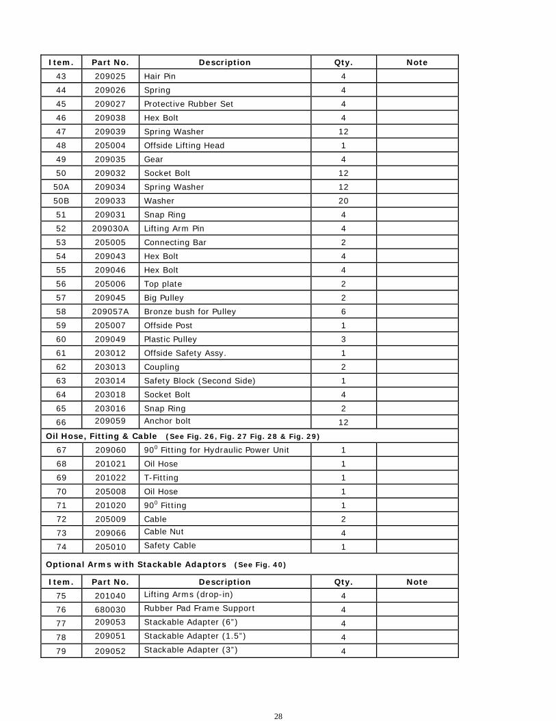
Item. Part No. Description Qty. Note 43 209025 Hair Pin 4
44 209026 Spring 4
45 209027 Protective Rubber Set 4
46 209038 Hex Bolt 4
47 209039 Spring Washer 12
48 205004 Offside Lifting Head 1
49 209035 Gear 4
50 209032 Socket Bolt 12
50A 209034 Spring Washer 12
50B 209033 Washer 20
51 209031 Snap Ring 4
52 209030A Lifting Arm Pin 4
53 205005 Connecting Bar 2
54 209043 Hex Bolt 4
55 209046 Hex Bolt 4
56 205006 Top plate 2
57 209045 Big Pulley 2
58 209057A Bronze bush for Pulley 6
59 205007 Offside Post 1
60 209049 Plastic Pulley 3
61 203012 Offside Safety Assy. 1
62 203013 Coupling 2
63 203014 Safety Block (Second Side) 1
64 203018 Socket Bolt 4
65 203016 Snap Ring 2
66 209059 Anchor bolt 12
Oil Hose, Fitting & Cable (See Fig. 26, Fig. 27 Fig. 28 & Fig. 29) 67 209060 900 Fitting for Hydraulic Power Unit 1 68 201021 Oil Hose 1 69 201022 T-Fitting 1
70 205008 Oil Hose 1 71 201020 900 Fitting 1 72 205009 Cable 2
73 209066 Cable Nut 4 74 205010 Safety Cable 1
Optional Arms with Stackable Adaptors (See Fig. 40)
Item. Part No. Description Qty. Note 75 201040 Lifting Arms (drop-in) 4 76 680030 Rubber Pad Frame Support 4 77 209053 Stackable Adapter (6”) 4
78 209051 Stackable Adapter (1.5”) 4 79 209052 Stackable Adapter (3”) 4
29
Item. Part No. Description Qty. Note
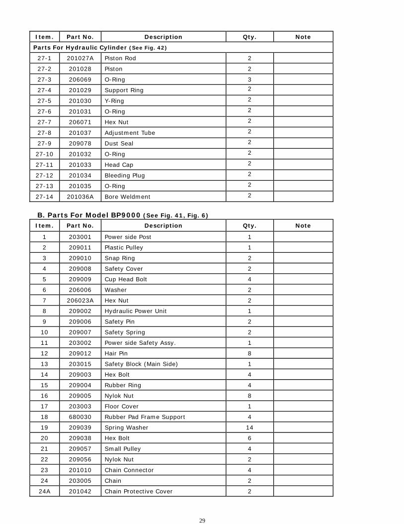
Parts For Hydraulic Cylinder (See Fig. 42)
27-1 201027A Piston Rod 2
27-2 201028 Piston 2
27-3 206069 O-Ring 3
27-4 201029 Support Ring 2
27-5 201030 Y-Ring 2
27-6 201031 O-Ring 2
27-7 206071 Hex Nut 2
27-8 201037 Adjustment Tube 2
27-9 209078 Dust Seal 2
27-10 201032 O-Ring 2
27-11 201033 Head Cap 2
27-12 201034 Bleeding Plug 2
27-13 201035 O-Ring 2
27-14 201036A Bore Weldment 2
B. Parts For Model BP9000 (See Fig. 41, Fig. 6) Item. Part No. Description Qty. Note
1 203001 Power side Post 1
2 209011 Plastic Pulley 1
3 209010 Snap Ring 2
4 209008 Safety Cover 2
5 209009 Cup Head Bolt 4
6 206006 Washer 2
7 206023A Hex Nut 2
8 209002 Hydraulic Power Unit 1
9 209006 Safety Pin 2
10 209007 Safety Spring 2
11 203002 Power side Safety Assy. 1
12 209012 Hair Pin 8
13 203015 Safety Block (Main Side) 1
14 209003 Hex Bolt 4
15 209004 Rubber Ring 4
16 209005 Nylok Nut 8
17 203003 Floor Cover 1
18 680030 Rubber Pad Frame Support 4
19 209039 Spring Washer 14
20 209038 Hex Bolt 6
21 209057 Small Pulley 4
22 209056 Nylok Nut 2
23 201010 Chain Connector 4
24 203005 Chain 2
24A 201042 Chain Protective Cover 2

30
Item. Part No. Description Qty. Note
25 201008 Hydraulic Cylinder 2
26 201007 Pin For Chain Pulley 2
27 203004 Chain Pulley 2
27A 203004A Bronze bush for Chain Pulley 4
28 201005 Split Pin 2
29 201004 Chain Pulley Assy. 2
30 203007 Power side Lifting Head 1
31 206044 Slider 16
32 209016 Carriage Plastic Cover 2
33 206045 Protective Rubber 2
34 206046 Self-tapping Screw 4
35 209020 Plastic Ball 4
36 209021 Hex Nut 12
37 209022 Washer 12
38 209023A Teeth 4
39 209024 Arm Lock Bar 4
40 209025 Hair Pin 4
41 209026 Spring 4
42 209027 Protective Rubber Set 4
43 201012C Lifting Arm - Front Right (Drop-in) 1
44 201013C Lifting Arm - Front Left (Drop-in) 1
45 201014B Lifting Arm - Rear Left (Drop-in) 1
46 203008 Offside Lifting Head 1
47 201016B Lifting Arm - Rear Right (Drop-in) 1
48 209035 Gear 4
49 209033 Washer 20
50 209034 Spring Washer 12
51 209032 Socket Bolt 12
52 209030 Lifting Arm Pin 4
53 203009 Connecting Bar 2
54 209043 Hex Bolt 8
55 209046 Hex Bolt 4
56 203010 Top plate 2
57 209045 Big Pulley 2
58 209057A Bronze Bush For Pulley 6
59 203011 Offside Post 1
60 209049 Plastic Pulley 3
61 203012 Offside Safety Assy. 1
62 203013 Coupling 2
63 203014 Safety Block (Second Side) 1
64 203018 Socket Bolt 4
65 203016 Snap Ring 4
65A 209051 Stackable Adapter (1.5”) 4

31
65B 209052 Stackable Adapter (3”) 4
Item. Part No. Description Qty. Note
65C 209053 Stackable Adapter (6”) 4
66 209059 Anchor bolt 12 Oil Hose, Fitting & Cable (See Fig. 26, Fig. 27 Fig. 28 & Fig. 29)
67 209060 900 Fitting for Hydraulic Power Unit 1
68 201021 Oil Hose 1
69 201022 T-Fitting 1
70 203019 Oil Hose 1
71 201020 900 Fitting 1
72 203020 Cable 2
73 209066 Cable Nut 4
74 203021 Safety Cable 1
Optional Amy Kits With Screwed Rubber Pads (See Fig. 41)
75 201016 Lifting Arm - Rear Right (Screw-in) 1
75A 201014 Lifting Arm - Rear Left (Screw-in) 1
76 201012 Lifting Arm - Front Right (Screw-in) 1
76A 201013 Lifting Arm - Front Left (Screw-in) 1
77 206031 Inner Screw Assy. 4
78 206032 Snap Ring 4
79 206034 Outer Screw 4
80 206033 Snap Ring 8
Parts For Hydraulic Cylinder (See Fig. 43)
25-1 201027 Piston Rod 2
25-2 201028 Piston 2
25-3 206069 O-Ring 2
25-4 201029 Support Ring 2
25-5 201030 Y-Ring 2
25-6 201031 O-Ring 2
25-7 206071 Hex Nut 2
25-8 201037 Adjustment Tube 2
25-9 209078 Dust Seal 2
25-10 201032 O-Ring 2
25-11 201033 Head Cap 2
25-12 201034 Bleeding Plug 2
25-13 201035 O-Ring 2
25-14 201036 Bore Weldment 2

32
Parts List Of Power Unit For Model 209 & 209X (See Fig. 44)
Parts For SPX Power Unit
Item. Part No. Description Qty. Note
8-1 209082 Motor 1
8-2 209109 Protective Ring 1
8-3 209083 Motor Connecting Shaft 1
8-4 209084 Valve Body 1
8-5 209085 Relief Valve 1
8-6 209086 Spring Washer 4
8-7 209087 Socket Bolt 4
8-8 209088 Inlet Pipe 1
8-9 209089 O-Ring 1
8-10 209090 Filter 1
8-11 209091 Hex bolt 4
8-12 209092 Reservoir 1
8-13 209093 Bolt 2
8-14 209094 Cover of Capacitor 1
8-15 209095 Capacitor 1
8-16 209096 Rubber Gasket 1
8-17 209097 Hex bolt 1
8-18 209098 Cover of Motor Terminal Box 1
8-19 209099 Push Button 1
8-20 209110 Oil Return Port 1
8-21 209100 Oil Outlet 1
8-22 209101 Release Valve 1
8-23 209102 Handle For Release Valve 1
8-24 209103 Washer 1
8-25 209104 Hex Nut 1
8-26 209105 Check Valve 1
8-27 209106 Gear Pump 1
8-28 209107 Oil Return Pipe 1
8-29 209108 Filler Cap 1

33
Parts For PEAK Power Unit
Item. Part No. Description Qty. Note
8A-1 209082A Motor 1
8A-2 209109 Protective Ring 1
8A-3 209112 AC contactor 1
8A-4 209083A Motor Connecting Shaft 1
8A-5 209084A Valve Body 1
8A-6 209085A Relief Valve 1
8A-7 209113 Throttle valve 1
8A-8 209086A Spring Washer 4
8A-9 209087A Socket Bolt 4
8A-10 209088A Inlet Pipe 1
8A-11 209089A O-Ring 1
8A-12 209090A Filter 1
8A-13 209091A Socket bolt 4
8A-14 209092A Reservoir 1
8A-15 209093A Cup Head Bolt 4
8A-16 209094A Cover of Capacitor 2
8A-17 209095A Capacitor 2
8A-18 209096A Rubber Gasket 2
8A-19 209097A Cup Head Bolt 2
8A-20 209098A Cover of Motor Terminal Box 1
8A-21 209099A Push Button 1
8A-22 209110A Oil Return Port 1
8A-23 209100A Oil Outlet 1
8A-24 209105A Check Valve 1
8A-25 209101A Release Valve 1
8A-26 209102A Handle For Release Valve 1
8A-27 209103A Washer 1
8A-28 209104A Hex Nut 1
8A-29 209106A Gear Pump 1
8A-30 209107A Oil Return Pipe 1
8A-31 209108A Filler Cap 1