atlas genset - soundtraxx · atlas genset tsunami digital sound decoder installation notes overview...
TRANSCRIPT
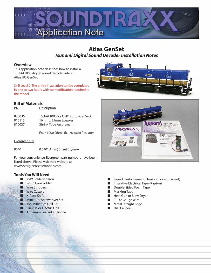
Atlas GenSetTsunami Digital Sound Decoder Installation Notes
OverviewThis application note describes how to install a TSU-AT1000 digital sound decoder into an Atlas HO GenSet.
Skill Level 2: The entire installation can be completed in one to two hours with no modification required to the model.
Bill of MaterialsP.N. Description
828036 TSU-AT1000 for QSK19C x3 (GenSet)810113 16mm x 35mm Speaker810037 Shrink Tube Assortment
Four, 1000 Ohm (1k, 1/8 watt) Resistors
Evergreen P.N.
9040 0.040” (1mm) Sheet Styrene
For your convenience, Evergreen part numbers have been listed above. Please visit their website at www.evergreenscalemodels.com.
Tools You Will Need■ 25W Soldering Iron■ Rosin Core Solder■ Wire Strippers■ Wire Cutters■ X-Acto Knife■ Miniature Screwdriver Set■ #55 Miniature Drill Bit■ Pin Vise or Electric Drill■ Aquarium Sealant / Silicone
■ Liquid Plastic Cement (Tenax 7R or equivalent)■ Insulative Electrical Tape (Kapton)■ Double-Sided Foam Tape■ Masking Tape■ Heat Gun or Blow Dryer■ 30-32 Gauge Wire■ Metal Straight Edge■ Dial Calipers

Installation
1. To separate the shell from the frame, the shell and the coupler boxes on each end need to be removed. Start by removing the Phillips-head screws holding the box in place on each end. Gently pull the coupler boxes out from each end. (Photo 1)
2. Lift the shell off by gently wiggling it from side to side while lifting from the frame. (Photo 2)
3. Familiarize yourself with the wiring and label the wires with the masking tape as needed (see the diagram at the end of this document). To remove the wires from the board, remove the small black plastic clips by pulling them off the board, then pull the wire from the tab.
4. There are four screws holding the circuit board in place, one in each of the four corners. Remove these and simply lift the board from the model. (Photo 3)
5. After the board has been removed, remove the rear weight by removing one screw near the end of the loco. The wires for the track pickup are lying in a small channel on the side of the weight and the ditch light wires are taped into a channel on top of the weight. Pull these wires away from the weight and lift the weight off the frame. (Photos 4 and 5)
Photo 1
Photo 2
Photo 3
Photo 4
Photo 5

11. To help mount the decoder, and to insulate the terminals at the end of the TSU-AT1000 decoder from the metal weights, place two small pieces of double-sided foam tape on the shelf of each weight. (Photo 8)
12. Start by soldering the right track pickup wires (T-R) to tabs 1 and 10 and left track pickup wires (T-L) to tabs 4 and 7. Motor wires (M+ and M-) to tabs 5 and 6. Speaker wires to S+ and S-. Since only one speaker is used, polarity is not important. Trim off any excess wire below the tab after soldering to prevent the wires from protruding through the foam tape and protecting against any possible short circuits.
13. With the decoder ‘fl oating’ on the model, take it for a quick test run under address 3. There will be sound and motor control, but no lights. Fix any problems encountered at this time.
6. Under the weight is a place perfectly designed for our 16mm x 35mm speaker. At this time, solder two 3” sections of 30-32 gauge wire to the speaker terminals. (Photo 6)
7. Thread the speaker leads up through the opening in the back of the weight. (Photo 7)
8. Note the locations for screws in two of the corners of the speaker baffl e assembly. Using two of the screws removed in Step 4, secure the speaker into the baffl e assembly.
9. Next, because this opening does not fully baffl e the speaker, cut a 7mm x 10mm piece out of 1mm styrene. Drill two small holes in the styrene for the wires to go through. Thread the wires through the holes and cement the styrene into the opening using silicone.
10. Replace the weight assembly back into the frame and replace the screw holding it in place.
Photo 6
Photo 7
Photo 8
Photo 9

14. Slide a 1/2” section of heat-shrink tubing over the black lead for the headlight, backup light, and each pair of ditch lights. Trim one lead of each of the four 1000 ohm (1k) resistors to 3/8” long. Solder this end of each resistor to the end of each black wire. Slide the tubing over the joint and apply heat to insulate the joint. (Photo 10)
15. Trim the other lead of the resistor to 3/8” long and solder to the respective outputs on the decoder. Solder the headlight to tab 3, backup light to tab 8, front ditch lights to the FX5 terminal and the reverse ditch lights to the FX6 terminal. Again, trim any excess resistor lead protruding below each of the tabs.
16. Collect the remaining red wires and solder the two front positive leads to tab 2 and the two reverse positive leads to tab 9. Cut any excess wire below these tabs.
17. Remove the protective backing from the foam tape and press the decoder down to secure in place. Be sure the decoder is centered and the tabs are not touching the metal weights.
18. Cut a small piece of double-stick foam tape and apply to the underside of the rear weight/baffl e assembly in the recession above the drive line. Bend the leads of the capacitor gently and secure against the tape with the leads coming up through the channel with the track pickup wire.
19. Using Kapton tape, secure any stray wires to the weights. Wrap some tape over the the decoder as needed to secure in place against the foam tape. (Photo 11)
20. Replace the shell, ensuring any headlight and backup light loose wires are above the decoder and do not interfere with the motor or drive line.
21. Replace the coupler boxes.
Have fun!
Photo 10
Photo 11

Front Right Pickup
Front Left Pickup
RearRight Pickup
RearLeft Pickup
Motor
Function Common Function Common
Headlight Backup Light
FX
6
FX
5
1 2 3 4
107
8
9
FWD
REV ALED25 6
Motor -
Motor +
TSU_AT1000_INSTALL_1.EPS
TM
New Dimensions in Digital Sound Technology
©2013 Throttle Up! Corp.All Rights Reserved
141 Burnett Drive • Durango, CO 81301Phone: (970) 259-0690 • Toll Free: 888-789-7637 • Fax: (970) 259-0691
Email: [email protected] • Website: www.soundtraxx.com
Front Right Pickup
Front Left Pickup
RearRight Pickup
RearLeft Pickup
Hea
dlig
ht
Bac
kup
Ligh
t
Mot
or -
Mot
or +
Ditc
h Li
ght
Ditc
h Li
ght
Factory Board:
TSU-AT1000 Wiring Diagram:
Styrene Piece:
10mm
7mm