atlast-8 mission concept study for 8-meter monolithic … · atlast-8 mission concept study for...
TRANSCRIPT

Space Telescopes and Instrumentation 2010: Optical, Infrared, and Millimeter Wave, Proceedings of SPIE Volume 7731 (2010)
ATLAST-8 Mission concept study for
8-meter Monolithic UV/Optical Space Telescope
H. Philip Stahla, Marc Postman
b, William R. Arnold Sr.
c, Randall C. Hopkins
a,
Linda Hornsbyc, Gary E. Mosier
d, and Bert A. Pasquale
d
aNASA Marshall Space Flight Center, Huntsville, AL bSpace Telescope Science Institute, Baltimore, MD
cJacobs ESTS Group, Marshall Space Flight Center, Huntsville, AL
dNASA Goddard Space Flight Center, Greenbelt, MD
ABSTRACT
ATLAST-8m is an 8-meter monolithic UV/optical/NIR space observatory which could be placed in orbit at Sun-Earth L2
by a heavily lift launch vehicle. Two development study cycles have resulted in a detailed concept including a dual foci
optical design; several primary mirror launch support and secondary mirror support structural designs; spacecraft
propulsion, power and pointing control design; and thermal design. ATLAST-8m is designed to yield never before
achieved performance to obtain fundamental astronomical breakthroughs.
Keywords: Large Space Telescopes, UV/Optical Space Telescopes, Astronomy, Heavy Lift Launch Vehicle
1. INTRODUCTION
ATLAST-8m is an 8-meter monolithic UV/optical/NIR space observatory which could be placed in orbit at Sun-Earth L2
by a heavy lift launch vehicle with capabilities similar to the NASA Ares V cargo launch vehicle. (1, 2, 3) ATLAST-8m is
one of three mission concepts (ATLAST-8m, ATLAST-9m and ATLAST-16m) studied by the Astrophysics Mission
Concept Study Advanced Technology Large-Aperture Space Telescope (ATLAST) effort lead by Marc Postman of the
Space Telescope Science Institute (STScI). (4) ATLAST-8m started in 2006 as a 6 to 8 meter joint concept study between
Marshall Space Flight Center (MSFC) and STScI. Preliminary results of this initial study were presented at the Tempe
2007 Science Associated with Lunar Exploration Architecture Meeting (5, 6) and several other conferences. (7, 8, 9) Upon
receiving the Astrophysics Concept Study in 2008, the ATLAST-8 team was expanded to include Goddard Space Flight
Center (GSFC), Ball Aerospace Technology Corporation and Northrop Grumman.
The result of the Astrophysics Study is a detailed concept (4) with a dual foci optical design (10); primary mirror launch
support and secondary mirror support structural design (11); spacecraft propulsion, power and pointing control design (12);
and thermal design (13). ATLAST-8m is an 8-meter monolithic telescope with 50 m2 collecting aperture. Specific on-axis
and off-axis configurations were explored. It assumes the same optical coatings as used on the Hubble Space Telescope for
broadband UV/OIR (110 nm to 2400 nm) performance. With a 10 nm rms primary mirror and an extremely stiff structure,
ATLAST-8m is able to achieve a system level diffraction limited of 500 nm. And, ATLAST-8m has sufficient pointing
stability to take full advantage of its 16 milli-arc-sec (mas) angular resolution. The 10 nm rms primary mirror surface
figure error is achieved because ATLAST-8m assumes a massive solid meniscus primary mirror (which can be polished
with no quilting). And, because of the primary mirror thermal mass, ATLAST-8m has an extremely stable 500 hour
thermal time constant. Innovative spacecraft design features enable 4500 to 9000 hours of pointing stability for long
exposure observations. The combination of these engineering parameters results in a space observatory with never before
achieved performance which will enable ATLAST-8m to study some of the most compelling science questions of our
generation and yield fundamental astronomical breakthroughs. (14, 15) Additionally, a one year study was funded at the
University of Alabama Huntsville to explore multiple robotic servicing options for ATLAST-8m.
Finally, it is true that ATLAST-8m is wholly dependent upon the existence of a heavy lift launch vehicle with capacities
similar to the NASA Ares V vehicle, i.e. a 10 meter diameter by 23 meter tall fairing and 56 mT mass to Sun-Earth L2
Transfer Orbit. But, given the length of time needed to design, build and launch space telescopes (26 years for Hubble, 24
years for Chandra, and at least 24 years for JWST), it is recommended that ATLAST-8m be developed in parallel with
NASA‟s new heavy lift launch vehicle. Because of its low risk high technical level maturity, ATLAST-8m could be ready
to launch by mid to late 2020s. After JWST, ATLAST-8m is ready to be the next „Great Observatory‟ of the 21st Century.
https://ntrs.nasa.gov/search.jsp?R=20100036714 2018-07-07T18:09:17+00:00Z

Space Telescopes and Instrumentation 2010: Optical, Infrared, and Millimeter Wave, Proceedings of SPIE Volume 7731 (2010)
2. SCIENCE MOTIVATION
The science case for ATLAST is compelling (14, 15). ATLAST-8m has the performance necessary to answer some of the
most compelling astronomical questions, including: Is there life elsewhere in the Galaxy?; What is the underlying physics
driving star formation?; and What are the complex interactions between dark matter, galaxies and the intergalactic medium?
By virtue of its ~15 milli-arcsec (mas) angular resolution at ~500 nm coupled with its ultra high sensitivity, superb stability
and low sky background, ATLAST-8m will achieve major breakthroughs in astrophysics by enabling fundamentally new
observations – both on its own and in combination with other telescopes with different capabilities. ATLAST-8m has the
performance required to detect the potentially rare occurrence of bio-signatures in the spectra of terrestrial exo-planets, to
reveal the underlying physics that drives star formation, and to trace the complex interactions between dark matter,
galaxies, and the intergalactic medium. ATLAST-8m will be able to observe the habitable zone of 145 long-lived stars
(spectral type F,G,K) up to ~ 25 parsecs (Figure 1). ATLAST-8m can determine planetary rotation rates, the presence of
continents, oceans, and clouds as well as determine planetary habitability and the possible presence of life by obtaining
spectra of ozone, molecular oxygen, atmospheric column density and Rayleigh scattering, and water vapor. The spectral
features required to assess the above processes are all in the 300 – 2400 nm range and, hence, the exo-planet
characterization instrument on ATLAST is sensitive at these wavelengths. ATLAST-8m will be able to study star
formation histories in the local universe by measuring accurate colors and luminosities of stars in over 100 galaxies, of
which over ten are giant spirals and one is a giant elliptical (Figure 2). And, it can study dark matter by determining subtle
transverse motions of stars to measure density profiles in dwarf spherioid galaxies. ATLAST-8m will be able to study the
relationship between galaxy formation and super massive black holes by obtaining spatially resolved images and spectra of
the disks of accreting gas around 1740 super massive black holes out to a redshift of 0.36. And, it will enable the study of
galaxy and large structure formation by directly measuring key properties (both for dark and visible matter) of structures
and mapping their evolution in time. Because of the large leap in observing capabilities that ATLAST-8m provides, one
cannot fully anticipate the diversity or direction of the investigations that will dominate its use – just as the creators of HST
did not foresee its pioneering roles in characterizing the atmospheres of Jupiter-mass exoplanets or measuring the
acceleration of cosmic expansion using distant supernovae.
3. MISSION CONCEPT
ATLAST-8m is intended to be launched from KSC on a heavy lift launch vehicle with capabilities similar to the Ares V
vehicle (configuration 51.01.48), which could place 65 mt of payload onto a transfer orbit with a C3 energy of -0.7 km2/s
2.
This energy is sufficient to send ATLAST-8m to a halo orbit about the second Sun-Earth Lagrange point (SE-L2) using a
direct insertion trajectory [2, 3]. While the NASA Constellation Program is in a state of flux, there appears to be a National
commitment to design and build a heavy lift launch vehicle. Several current heavy lift design studies at MSFC are
including the ATLAST-8m observatory in the trade space of potential payloads that define the desired capabilities of a
future heavy lift launch vehicle. Preliminary results indicate that ATLAST-8m is not a driving element for any potential
heavy lift vehicle. Beyond mass to orbit, the key capacity requirement which enables ATLAST-8m is launch faring
volume. The ATLAST-8m concept requires a dynamic envelope of at least 8.8 meters diameter by 17 meters tall (Figure
3). The Ares V 10 meter diameter by 23 meter tall fairing provided this envelope. The 8.8 m diameter dynamic envelop
allows an 8 m diameter primary mirror to be launched face up (which is best for launch survival purposes). The 17 m tall
dynamic envelop allows for the secondary mirror to be launched fully deployed. This reduces risk and allows for a
structurally stiff and stable optical bench and secondary mirror support structure.
Figure 2: Map of local
universe (24 Mpc across)
shown with distances out
to which HST (yellow),
JWST (orange), and
ATLAST (8-m, 16-m),
can detect solar analogs
in V and I pass-bands at
SNR=5 in 100 hours.
Giant spirals, like M31,
are indicated by blue
galaxy symbols, giant
ellipticals as orange
blobs, and dwarf galaxies
as green dots.
1
10
100
1000
2m 4m 8m 16m
Figure 1: Average number of F,G,K stars where
SNR=10 R=70 spectrum of an Earth-twin could be
obtained in < 500 ksec as a function of telescope
diameter. Growth in the sample size scales as D3.

Space Telescopes and Instrumentation 2010: Optical, Infrared, and Millimeter Wave, Proceedings of SPIE Volume 7731 (2010)
Once on-orbit, the 60 degree scarfed forward sunshield slides forward, the protective doors open, the solar panels deploy,
and the optical component launch locks release (Figure 4). At this point the observatory is ready for commissioning and
alignment of the optical system. The wavefront sensing and control system iteratively uses the star trackers and fine
guidance sensors to point stars onto phase-diversity sensors distributed about the observatory field of view. Alignment is
achieved by moving the secondary mirror via its hexapod and if necessary the tertiary mirror.
The size and geometry of the halo orbit can be traded during Phase A, but is assumed to be the JWST orbit. This orbit has
the advantage of not requiring an insertion maneuver at SE-L2. Once at SE-L2 the spacecraft only has to begin station
keeping duties to remain on the halo orbit. Available volume in the ATLAST-8 structure and mass margin makes it
possible to add extra propellant tanks and carry a sufficient propellant load for a 20 year (or longer) mission. Analysis
indicates that only 5 m/s delta-v is needed per year for station keeping and momentum unloading. Given the 6-month
period of the halo orbit and the 60-degree keep-out angle between the telescope‟s line of sight and the sun, the telescope
can see the entire sky in approximately six months.
4. OBSERVATORY DESIGN
The fundamental philosophy of ATLAST-8m is to trade mass for simplicity. Instead of pursuing a complex design
imposed by a launch vehicle mass and volume constraint, the design team used the unparalleled capabilities of NASA‟s
potential Ares V launch vehicle to design a simple low risk observatory using high TRL (but massive) technology. Using
mass reduces technical, programmatic and performance risk, and cost. A study of space telescope missions has discovered
that telescopes without a launch mass constraint tended to be 10X more massive and 60% lower cost than those with a
design to mass constraint [16]. Mass has performance advantages as well. A more massive telescope is stiffer. Therefore
it is more mechanically and thermally stable. Also, it is easier to achieve exceptionally smooth optical surfaces on a solid
mirror substrate. Finally, the volume of an Ares V class vehicle allows the launch of a fully deployed telescope.
The ATLAST Astrophysics Mission Concept Study developed a detailed point design for an 8-m monolithic observatory.
Specific studies included: optical design; structural design/analysis including primary mirror support structure, sun shade
and secondary mirror support structure; thermal analysis; spacecraft conceptual design including structure, propulsion,
GN&C, avionics, thermal and power systems; mass and power budgets; and system cost [4].
4.1 Optical Telescope Assembly
Optical Design: The optical telescope assembly (OTA) has a dual-field design with three foci (Figure 5). (10) All three
foci are diffraction limited at 500 nm. The main telescope is a two-mirror system, which forms a narrow-field-of-view
(NFOV) 1 arc-min Cassegrain (CASS) image. The Cassegrain focus provides specific technical advantages for two classes
of high-priority science. It provides a high quality NFOV focus for exo-planet characterization science, and it provides a
Figure 3: ATLAST-8m in its launch
configuration in an Ares-V ogival fairing.
The scarfed end of the sunshade is deployed
once on-orbit. Length scales are in meters.
Figure 4: ATLAST-8m exterior view showing twin gimbaled solar arrays.

Space Telescopes and Instrumentation 2010: Optical, Infrared, and Millimeter Wave, Proceedings of SPIE Volume 7731 (2010)
high-throughput two-bounce path for UV spectroscopy science. The primary and secondary mirrors‟ optical coatings are
identical to what was used by HST: aluminum with MgF2 overcoat to provide good spectral transmission from 110 nm to
2400 nm. These coatings are important to the UV science instruments at Cassegrain focus. Two pick-off fold mirrors, on
either side of CASS focus, direct off-axis portions of the Cassegrain image plane to two tertiary-mirror aft-optics
assemblies, which form two wide-field-of-view (WFOV) 8 x 22 arc-min three-mirror anastigmatic (TMA) images. The
TMA provides a 13 mas plate scale. The aft optics are coated with protected silver as used on Kepler for enhanced
visible/near-ir spectral transmission. All three foci are directly accessible to a 4.0 m diameter by 4.5 m deep instrument bay
centered on-axis behind the primary mirror.
Figure 5: Optical Layout of 8-m OTA showing 2 TMA foci and Cass focus (at red dot)
Additionally, for exo-planet science, an off-axis dual-field optical design was developed. Conventional internal Lyot stop
coronagraphs desire a „clean‟ point spread function without diffraction from secondary mirror support structure. The
resultant design has two potential problems. First, because of the size of the secondary mirror and the need to keep its
shadow clear of the primary mirror, the maximum primary mirror aperture which can be implemented is approx 6x8 meters.
Second, to keep the primary mirror surface aspheric departure slope and alignment tolerances reasonable, the secondary to
primary mirror distance is 12 meters. Given current launch faring sizes, this design would require a deployed secondary.
Primary Mirror: The single most important element of ATLAST-8m is the primary mirror. While a HST-style or
(proposed TPF-C style) lightweight mirror could be used with a JWST-class design-margin structure, the mass capacity of a
potential heavy lift launch vehicle allows us to reduce risk and cost by using a solid meniscus glass mirror – the kind
typically used for ground based telescopes (e.g., Gemini, VLT and Subaru). Such mirrors offer several significant
advantages for a space-based telescope. They are extremely thermally stable, mechanically very stiff, and they cost
effectively achieve a very smooth optical surface. These are all properties that are important for ultra-high contrast
imaging. Both REOSC and Brashear have demonstrated the ability to fabricate 8 m class mirrors to better than 10 nm rms.
This fact highlights another important advantage of the proposed mirror: the infrastructure exists and is proven for
handling, manufacturing, and testing 8 m class mirrors. Currently there is one existing 8 m Zerodur mirror blank at Schott
Glass in Germany and Corning has a proven furnace capability to make ULE glass mirror blanks.
The secondary mirror can be made of ULE or Zerodur. While the SM could be a lightweight mirror, the baseline is a solid
meniscus. Again, the advantage of a solid meniscus is a lower cost and smother mirror than can be achieved with a
lightweighted mirror. A lightweighted mirror will only be considered if analysis shows that reducing SM assembly mass is
required to meet launch environment design safety margins. A solid meniscus mirror also enables the ability to certify its
convex aspheric surface figure using a through the back test. The SM assembly employs a six-degree-of- freedom hexapod
virtually identical to the one to be used on JWST.
Science Instruments: A notional concept has five science instruments and two facility instruments (Figure 6). The
exoplanet instrument and UV spectrometer are at CASS focus. The WFOV imager, multi-object spectrograph and IFU
spectrograph are divided between the two TMA focal planes. Additionally, each of the three foci has wavefront sensors
and each TMA focus has two Fine Guidance Sensors (FGS). Each instrument module is a self-contained On-orbit
Replaceable Unit (ORU) using HST-style mounting rails accessible from the back of the instrument bay to facilitate
servicing missions. The instrument bay provides all required mechanical, electrical, data and thermal interface connections
for the science modules using standard HST-style „blind-mate‟ connectors. Heat-pipe connections scavenge instrument
heat to help maintain the OTA at 280 deg K and route excess heat to external radiators. The spacecraft envelope surrounds
the instrument bay, which is isolated from both the primary mirror support structure and the instrument bay. The
Instrument Command and Data Handling unit (IC&DH) provides centralized OTA electronics for control of telescope
mechanisms and heaters, wavefront sensing (WFS) processors, and science instruments.

Space Telescopes and Instrumentation 2010: Optical, Infrared, and Millimeter Wave, Proceedings of SPIE Volume 7731 (2010)
Figure 6: Cassegrain and TMA Foci Instrument Allocations.
The two TMA FOVs are separated on the sky by approximately 0.5 degrees. This separation helps the FGS pointing
system control roll well enough to meet the 1.6 mas pointing stability requirement. Separating the two WFOV instruments
allows added flexibility in packaging as well as future functionality after a servicing mission.
Structure: The ATLAST-8m structure contains several major elements (Figure 7): primary mirror support structure,
metering truss, instrument bay, secondary mirror spiders, aft optics structure and payload adapter fixture. (11) All
structural elements are fabricated from a cyanate ester graphite epoxy composite material with flight certified thermal and
mechanical properties. The structure is divided between the forward and back structure.
Figure 7: ATLAST-8m Observatory Structural Layout
The forward structure is similar to that of the Hubble Space Telescope. It provides
the metering structure between the primary and secondary mirrors and holds the
straylight baffle tube. Because of fairing length limitations, the forward structure is
split into two parts. The lower structure is load carrying. It holds the secondary
mirror assembly support structure and the cover doors. The upper part contains the
60 degree baffle tube which slides forward on orbit. The cover doors open and close
on-orbit as required. A tripod structure extending from the primary to secondary
mirror was considered but determined to be unable to achieve the desired system
stiffness levels for an ultra stable telescope. A classic 4 arm secondary support
structure was initially baselined with a 10.3 Hz first fundamental mode. But, this
configuration presents diffraction challenges for internal coronagraphs. To solve this
problem, a double arch secondary mirror support system was developed (Figure 8).
This secondary support structure provides two 3x6 meter elliptical off-axis un-
obscured clear apertures for use with up to two separate coronagraphs (while
retaining the full 8 meter diameter clear aperture for conventional on-axis science
instruments). The first fundamental mode frequency for the double arch is 7.3 Hz.
The back structure has multiple functions. First, it supports the primary mirror
during launch. Second, the forward structure is attached to the back structure as are
the spacecraft and the science instruments. A key design element of the concept is
Figure 8: Double Arch Secondary
Mirror support structure provides
two 3x6 m un-obscured off-axis
clear apertures for Lyot stop
coronagraphy with a 7.3Hz first
mode while preserving advantages
of 8-m on-axis system.

Space Telescopes and Instrumentation 2010: Optical, Infrared, and Millimeter Wave, Proceedings of SPIE Volume 7731 (2010)
that all observatory mass (telescope, instruments and spacecraft) is carried through the back support structure to an interface
ring which attaches via the payload adapter fixture (PAF) to the launch vehicle. This allows the use of a completely
conventional spacecraft, i.e. it does not need extra mass because it does not provide the interface between the observatory
and the launch vehicle.
The fundamental structural design philosophies are simplicity, modularity, and redundancy. To mitigate assembly risk, the
structure is designed using a bolt-together truss structure of repeated components. Each component is fabricated with a
conservative design margin and tested individually. The most challenging engineering issue is the joint interface between
nearly 1300 components. The structure is designed to safely launch an 8-meter primary mirror and maintain the on-orbit
optical alignment necessary to achieve a 500 nm diffraction limited telescope. Using fault-tolerant design principles, the
PM support structure provides a 10X margin of safety by distributing the forces between 66 axial and lateral support points
to keep the primary mirror launch loads at least an order of magnitude below its design limit.
Thermal: A key feature of ATLAST-8m is its extreme thermal and mechanical stability. (13) The ATLAST-8m passive
thermal isolation system of MLI insulation, scarfed sun shade and straylight baffles are such that the observatory is cold-
biased for all permitted observation angles relative to the sun. This allows the use of an active thermal management system
to bring the observatory up to the desired 280 K operating temperature and to eliminate any systematic spatial or temporal
thermal variations. The primary mirror temperature is actively controlled using radiative heaters applied to the back and
sides. Approximately 60 independently controlled heater zones are required to minimize gradients through and across the
mirror. The primary mirror axial through-thickness thermal gradient is a negligible: 0.02 K. The secondary mirror and
optical bench structure is heated using the same methodology as HST. Given the enormous thermal mass of the ATLAST-
8m system, it is virtually immune to transient thermal events. A 20 degree slew or 30 degree roll produces only a 0.2 K
change in thermal gradients. The primary mirror thermal time constant is 500 hrs to produce a 1 nm rms figure change.
4.2 Spacecraft
The spacecraft provides all pointing, power, communication, data handling, station keeping, momentum unloading, and
thermal control for the ATLAST-8m telescope and its science instruments, and provides the propulsive maneuvers for
midcourse corrections. (12) Key requirements include enabling the observatory to slew 60 degrees in 90 minutes (required)
or 40 minutes (desired); ensuring a pointing stability of 1.6 mas; enabling the observatory to roll about the telescope‟s line
of sight by ± 30 degrees in 30 to 60 minutes, and provide a minimum of 4500 minutes continuous observing time before
momentum unloading is required. All subsystem components are sized with a 30% mass contingency and, when electrical
power is required, a 30% reserve is included.
The spacecraft is packaged in a donut-shaped volume (Figure 9) located at the rear of the OTA, surrounding the science
instrument bay. Designed for serviceability, key subsystem components are grouped into Orbital Replaceable Units
(ORUs) to enable communication elements, reaction wheel assemblies, and other components to be removed and replaced
during servicing. All ORUs, as well as science instruments, are removed from the rear of the spacecraft and science
instrument bay. To prevent transmission of vibration into the instruments, the spacecraft volume does not physically
contact the instrument bay. The spacecraft connects to the observatory structure through an active isolation system (e.g.
Lockheed disturbance free payload or Northrop active strut technology). The active isolation system is part of the Attitude
Control System (ACS). It isolates the science payload (OTA + science instruments) from spacecraft bus disturbances (e.g.,
vibrations from the reaction wheel assemblies), and provides fine pointing control for the science payload.
Figure 9: Modular Spacecraft Design Concept with solar panels stored inside the PAF and radiator panels and AR&D docking interfaces
mounted outside of the PAF.

Space Telescopes and Instrumentation 2010: Optical, Infrared, and Millimeter Wave, Proceedings of SPIE Volume 7731 (2010)
Attitude Control System (ACS): The main components of the ACS include the Fine Guidance Sensor (FGS); a coarse
pointing system on the SC that includes gyros, star-trackers, reaction wheel assemblies (RWA), and/or control moment
gyros (CMG), and sun sensors; a propulsion system that provides attitude control (in certain situations) and momentum
unloading; Active Vibration Isolation (AVI) System between the spacecraft and observatory; and software resident on the
SC Bus C&DH system that runs the ACS algorithms. Thrusters provide the means to unload momentum periodically. The
CMGs have flight heritage on Space Station and are used to achieve coarse pointing while RWs maintain that pointing for
extended observation periods. The AVI system eliminates jitter to achieve sub 1.6 mas pointing stability. There are two
potential approaches for the active vibration isolation system, Lockheed‟s disturbance free payload (Pedreiro 2003, Journal
of Guidance, Control and Dynamics, Vol 26, No. 5) and Northrop‟s active strut technologies. The active isolation system
has two roles. First, it isolates the science payload from SC bus disturbances, such as vibrations from the RWA. Second, it
provides fine pointing control for the science payload, which requires a pointing stability of 1.6 mas. The FGS system has
four FGS modules, two in each WFOV TMA focus (one active and one backup). ALTAST-8m controls pointing using
guide stars in two FGS modules separated on the sky by 0.5 degree. This separation provides roll control about boresight at
a lower bandwidth and with much better stability than the 0.2 mas rms requirement.
ATLAST-8m employs body pointing, similar to HST. The reason is driven by UV science. To maximize UV throughput,
telescope pointing places the science object of interest directly onto the entrance slit of the UV spectrograph. Star Trackers
command the OTA boresight pointed to within a few arc-sec of the desired target using the RWA/CMG. The active
isolation system then engages using FGS feedback to minimize the apparent motion of the guide star centroid for the
duration of that science exposure. During a science observation, sensors continuously monitor the travel of the AVI
actuators. This information is used by the ACS software to command the RWAs, changing the orientation of the SC bus so
as to maintain the AVI actuators at or near their center of travel. This feedback loop between FGS, AVI system, and RWA
continues until the end of the science observation. The reaction wheels provide 698 N-m-s of momentum storage capability
for a minimum of 4500 minutes continuous observation time. ATLAST-8m uses two solar panels on 10 m deployable
booms to balance solar pressure exerted on its sunshade tube. As the observatory slews relative to the sun, the solar panel
booms extend to keep the center of pressure as close as possible to the center of mass (Figure 10). Additionally, the booms
have gimbal joints that articulate during observatory roll and pitch maneuvers to keep the solar panels perpendicular to the
sun. Analysis shows that, with 10 meter booms extended from the spacecraft midpoint, only 35 N-m-s momentum is
required for 6.25 days of continuous high-precision pointing observation. And, by making slight adjustments in boom
length, indefinite observation times can theoretically be achieved.
Figure 10: Solar Torque / Momentum Build-Up Mitigation Scheme for ATLAST-8m
During launch, the spacecraft is attached to the rear of the telescope structure, and does not support the observatory nor
transfer launch loads to the launch vehicle (LV). Therefore, the structure is a lightweight and simple design, with aluminum
tube and aluminum-lithium plate elements being the main components. Structural elements were sized for 5g axial and 2g
lateral sustained loads, with a yield and ultimate factors of safety of 1.25 and 1.4, respectively. After separating from the
LV, the Solar Arrays (SA) and the steerable High Gain Antenna (HGA) are deployed.
Thermal Control System (TCS): The TCS provides thermal control for the spacecraft and science instruments, including
the OTA primary mirror. Radiators (30 m2) are mounted around the circumference of the OTA and spacecraft to dissipate
the 11,160 W of heat load from the spacecraft components and science instruments. Of the 2400 W required to maintain the
primary mirror at 280 K, 2000 W is scavenged from the science instruments via cold plates, although the TCS is designed
with 1600 W of backup in case the science instruments are powered down or are being serviced. The spacecraft is wrapped
in 50-layer MLI blankets, helping to maintain the spacecraft at an operational steady state sink temperature of 300 K
(±10K). The main functions of the TCS are to dissipate the heat from the power consumed by the SC and to keep the SC
Bus components in their operational temperature range.

Space Telescopes and Instrumentation 2010: Optical, Infrared, and Millimeter Wave, Proceedings of SPIE Volume 7731 (2010)
4.3 Mass and Power Budgets
Master Equipment Lists (MELs) were generated for each
component of the optical telescope assembly, instruments
and spacecraft. These MELs were used to estimate the
mass of the payload and to size the power system (Table
1). In table 1, the primary mirror is allocated 19,250 kg for
a 155 mm thick ULE mirror. With a 30% contingency, the
PM could be 25,000 kg. The existing Schott Zerodur blank
is close to 300 mm thick and has a 28 m radius of
curvature. Changing its radius to 24 m and removing top
and bottom surface damage yields a 175 mm thickness. If
a 175 mm thick Zerodur mirror is used, its mass would be
25,000 kg and the total payload mass would be 50,270 kg.
But, since the mirror cannot get more massive, the payload
mass margin against the Ares V 65,000 capacity is 29%
(60% excluding the mirror). If a 175 mm thick ULE mirror
is used, its mass would be 21,750 kg and the payload mass
margin would be 38%. For additional conservatism, the
ATLAST-8m OTA structure (primary mirror support
structure, launch locks and payload adapter fixture) is
„sized‟ based on a 25,000 kg primary mirror.
5. CONCLUSION
The ATLAST Astrophysics Concept Study has developed a detailed point design for an 8-meter monolithic aperture
UV/OIR space telescope called ATLAST-8m. The mission concept is specifically designed to take advantage of the
unprecedented mass and volume capabilities of a potential NASA heavy lift launch vehicle. The key fundamental design
paradigm for ATLAST-8m is simplicity. Simple high TRL technology offers lower cost and risk. The capacities of
potential heavy lift launch vehicles allow one to use mass to buy down performance, cost and schedule risk. An 8-meter
class UV/optical space observatory with its very high angular resolution, very high sensitivity, broad spectral coverage, and
high performance stability offers the opportunity to answer some of the most compelling science questions. How did the
present Universe come into existence and of what is it made? What are the fundamental components that govern the
formation of today's galaxies? How does the Solar System work? What are the conditions for planet formation and the
emergence of life? And maybe most importantly, are we alone?
ACKNOWLEDGEMENTS
The authors wish to acknowledge the contributions of David Jones, Dan Thomas, Sharon Fincher, Scott
Thomas, of NASA MSFC, Pete Capizzo of Raytheon, and Kevin Thompson of Jacobs, for spacecraft design and
configuration; and Jessica Garcia of Jacobs and Eric Waters of Dynamics Concepts, Inc. for Ares V
performance analysis.
Table 1: ATLAST-8m Mass and Power Budget
Parameter Value Units
Mass
Optical Telescope Assembly 33,908 kg
Primary Mirror Assembly 24,988 kg
Primary Mirror 19,250 kg
Primary Mirror Mount 5,738 kg
Secondary Mirror and Aft-Optics Assemblies 2,118 kg
Structure & Instrument Bay 5,360 kg
Thermal 1,442 kg
Instruments 1,789 kg
Spacecraft 4,157 kg
Propellant 4,666 kg
TOTAL PAYLOAD 44,520 kg
Launch Vehicle Payload Capacity 65,000 kg
Launch Vehicle Mass Margin (%) 46 %
Payload Mass if Primary Mirror = 25,000 kg 50270 kg
Launch Vehicle Mass Margin 15,270 kg
Payload Mass without Primary Mirror 25,270 kg
Payload Mass Margin (%) 60 %
Spacecraft Bus Power Requirement 8,589 W
Projected End of Life Solar Panel Production 11,200 W
Solar Panel Power Margin (%) 30 %
Space Telescopes and Instrumentation 2010: Optical, Infrared, and Millimeter Wave, Proceedings of SPIE Volume 7731 (2010)
REFERENCES
1. Stahl, H. Philip, Marc Postman, William R. Arnold Sr., Randall Hopkins, Linda Hornsby, Gary E. Mosier and Bert
A. Pasquale, “Design for an 8 meter monolithic UV/OIR space telescope”, SPIE Proceedings 7436, 2009.
2. Stahl, H. Philip, “Ares V launch capability enables future space telescopes”, SPIE Proc.6687, 66870L (2007)
3. Stahl, H. Philip, Phil Sumrall, and Randall Hopkins, “Ares V launch vehicle: an enabling capability for future
space science missions”, Acta Astronautica, Elsevier Ltd., 2009, doi:10.1016/j.actaastro.2008.12.017
4. ATLAST Astrophysics Mission Concept Study final report is available at: http://www.stsci.edu/institute/atlast
5. Postman, Marc, et. al., “A Large Monolithic-Aperture Optical/UV Serviceable Space Telescope Deployed to L2
by an Ares-V Cargo Launch Vehicle”, Science Associated with Lunar Exploration Architecture, Tempe, AZ, 28
Feb 2007
6. Stahl, “Ares V an Enabling Capability for Future Space Science Missions”, Science Associated with Lunar
Exploration Architecture, Tempe, AZ, 28 Feb 2007.
7. Hopkins, Randall and H. Philip Stahl, “A large monolithic telescope placed at the second Sun-Earth Lagrange
point”, AIAA Space 2007, AIAA-2007-6166, 2007
8. Stahl, H. Philip and Marc Postman, "8 meter Monolithic UV/Optical Space Telescope", 59th International
Astronautical Congress, Glasgow, Scotland, Sept 2008.
9. Stahl, H. Philip, "Design study of an 8 meter monolithic mirror uv/optical space telescope", SPIE Proc. 7010,
(2008)
10. Pasquale, Bert A., H. Philip Stahl, Joseph M. Howard, David L. Aronstein, Lee D. Feinberg and Qian Gong,
“Comparative Concepts for ATLAST Optical Designs”, SPIE Proceedings 7731, 2010.
11. Arnold, William R., and H. Philip Stahl, “Structural design considerations for an 8-m space telescope”, SPIE
Proceedings 7425, 2009.
12. Hopkins, Randall C., Peter Capizzo, Sharon Fincher, Linda S. Hornsby, David Jones, Gary Mosier, H. Philip
Stahl, Dan Thomas and Kevin S. Thompson, “Spacecraft conceptual design for the 8-meter Advanced Technology
Large Aperture Space Telescope (ATLAST)”, SPIE Proceedings 7731, 2010.
13. Hornsby, Linda, Randall C. Hopkins, H. Philip Stahl, “Thermal analysis of the Advanced Technology Large
Aperture Space Telescope (ATLAST) 8 meter primary mirror”, SPIE Proceedings 7731, 2010
14. Postman, Marc, et. al., “Science with an 8-meter to 16-meter optical/UV space telescope”, SPIE Proc.7010, (2008)
15. Postman, Marc, Wesley A. Traub, William R. Oegerle, Thomas M. Brown, H. Philip Stahl, Daniella Calzetti,
Dennis C. Ebbets, Ronald S. Polidan, “Science flowdown requirements for ATLAST: implications for technology
development and synergies with other future facilities“, SPIE Proceedings 7731, 2010.
16. Stahl, H. Philip, Kyle Stephens, Todd Henrichs, Christian Smart, and Frank A. Prince, “Single Variable Parametric
Cost Models for Space Telescopes”, Optical Engineering Vol.49, No.06, 2010

ATLAST-8 Mission concept study for 8-meter
Monolithic UV/Optical Space Telescope
H. Philip Stahl, NASA MSFC
Marc Postman, STScI
William R. Arnold, Sr., Jacobs ESTS Group, MSFC
Randall Hopkins, NASA MSFC
Linda Hornsby, Jacobs ESTS Group, MSFC
Gary E. Mosier, NASA GSFC
Bert A. Pasquale, NASA GSFC
Space Telescopes and Instrumentation 2010: Optical, Infrared, and Millimeter Wave Conference, SPIE 7731, 2010

History
Marc Postman of STScI, myself and the MSFC Advanced
Concepts Group Spacecraft Study Team lead by Randall
Hopkins have been working on massive 6 to 8 meter class
space telescopes since early 2007.
Postman, “A Large Monolithic-Aperture Optical/UV Serviceable Space
Telescope Deployed to L2 by an Ares-V Cargo Launch Vehicle”, Science
Associated with Lunar Exploration Architecture, Tempe, AZ Feb. 28, 2007
Stahl, “Ares V an Enabling Capability for Future Space Science Missions”,
Science Associated with Lunar Exploration Architecture, Tempe, AZ Feb.
28, 2007
Hopkins and Stahl, “A large monolithic telescope placed at the second Sun-
Earth Lagrange point”, AIAA Space 2007, AIAA-2007-6166, 2007
Which lead to the 2008 Multi-Institutional ATLAST
Astrophysics Mission Concept Study whose final report is
available at: http://www.stsci.edu/institute/atlast

ATLAST
The Astrophysics Mission Concept Study Advanced Technology
Large-Aperture Space Telescope (ATLAST) examined 3
different mission concepts:
ATLAST-8m (8-meter monolithic aperture)
ATLAST-9m (9.2 meter segmented aperture)
ATLAST-16m (16.8 meter segmented aperture)
All ATLAST concepts are UV/OIR (110 nm to 2400 nm)
ATLAST-8m will have exceptional performance capability:
• 16 milli-arc-sec (mas) angular resolution
• ~500 nm diffraction limit
• ~50 m2 collecting aperture
• 500 hour thermal time constant

Science
The science case for ATLAST is compelling and documented:
Postman, et. al., “Science flowdown requirements for ATLAST:
implications for technology development and synergies with other
future facilities “, SPIE Proceedings 7731, 2010.
Postman, Marc, et. al., “Science with an 8-meter to 16-meter optical/UV
space telescope”, SPIE Proc. 7010, 2008.
ATLAST-8m has the performance necessary to
detect the potentially rare occurrence of life.
reveal underlying physics driving star formation,
trace the complex interactions between dark matter, galaxies, and the
intergalactic medium

ATLAST-8 is fully Documented
ATLAST Astrophysics Mission Concept Study:
http://www.stsci.edu/institute/atlast/index_html_ATLASTMissionConceptStud
y_Page
Hopkins, et. al., “Spacecraft conceptual design for the 8-meter Advanced
Technology Large Aperture Space Telescope (ATLAST)”, SPIE 7731. 2010.
Hornsby, et. al., “Thermal analysis of the Advanced Technology Large Aperture
Space Telescope (ATLAST) 8 meter primary mirror”, SPIE 7731. 2010.
Pasquale, et. al., “Comparative Concepts for ATLAST Optical Designs”, SPIE
7731. 2010.
Arnold and Stahl, “Structural design considerations for an 8-m space telescope”,
SPIE 7425, 2009.
Stahl, et. al. “Design for an 8 meter monolithic UV/OIR space telescope”, SPIE
7436, 2009.
Stahl, "Design study of an 8 meter monolithic mirror uv/optical space telescope",
SPIE Astronomy Conference, Marseille, France, June 2008

While constellation is
currently in a state of flux,
MSFC is currently studying
several heavy lift vehicle
options, many of which
could launch ATLAST-8m.
LV 51.00.48 configuration used for ATLAST study.

Mission Concept – Launch Configuration
Fundamental idea is to trade Mass for Simplicity to increase
Performance and Reduce Risk.
ATLAST-8m is specifically designed to fully utilize the Ares V
payload mass and volume capacities.
8.8 m dia. dynamic envelop allows:
8 m diameter telescope
17 m tall dynamic envelop allows:
SM to be launched fully deployed.
65 mt payload mass allows:
solid meniscus glass mirror

ATLAST 8-meter in Ogive Shroud

Doors Open – view of light baffles
open doors before or after deploying tube

Observatory with 60 deg Light Tube

Mission Concept – On-Orbit
Once on orbit, the protective doors open, the 60 degree scarfed
sunshade slides forward and the solar panels deploy

Structure
ATLAST-8 structure major elements: primary mirror support
structure, metering truss, instrument bay, secondary mirror
spiders, aft optics structure and payload adapter fixture.
Height of HST style metering truss determined by faring.
Spacecraft and Science Instruments all attach to PM Structure
which carries entire load of Observatory through PAF to LV.
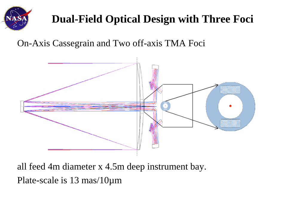
Dual-Field Optical Design with Three Foci
On-Axis Cassegrain and Two off-axis TMA Foci
all feed 4m diameter x 4.5m deep instrument bay.
Plate-scale is 13 mas/10µm

Notional Science Instruments
Cassegrain Focus could have 2 instruments (exoplanet & UV
spectrometer) and 2 WFS.
TMA Focus could have 3 instruments (WFOV Imager, Multi-
Object Spectrograph and Integral Field Unit spectrograph) and
2 FGS and 2 WFS.
Actual instruments will be based on a peer-reviewed competition,
driven by the most compelling science.
Vis/NIR
WFOV Imager
8 x 8 arc min
FGS
2 x 2
arcmin
FGS
2 x 2
arcmin
WFS WFS
MOS
4 x 4 arc min
IFU
4 x 4 arc min
FGS
2 x 2
arcmin
FGS
2 x 2
arcmin
WFS WFS
EXO
WFS15x15 arcsec
WFS15x15 arcsec
UV
Spec

Solid Meniscus Primary Mirror
Ares V‟s mass capacity allows us to reduce risk and cost by using
a solid meniscus glass mirror.
Such mirrors are extremely thermally stable & mechanically stiff.
A solid meniscus mirror also allows one to cost effectively
achieve a very smooth optical surface, a mirror property that is
important for ultra-high contrast imaging.
Infrastructure exists to make 8-m mirror blanks and fabricate
them to < 10 nm rms.

Primary Mirror Support Structure
Primary Mirror must survive launch and perform on orbit.
Mounts which work well on Earth do not work well in Space.
Design study resulted in a conventional truss structure mount.
PM structure provides 10X safety margin during launch via a combination
of 66 axial launch locks as well as radius and tangential supports.
Key is to minimize bending.
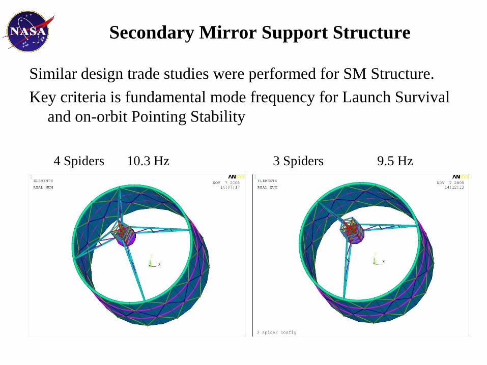
Secondary Mirror Support Structure
Similar design trade studies were performed for SM Structure.
Key criteria is fundamental mode frequency for Launch Survival
and on-orbit Pointing Stability
4 Spiders 10.3 Hz 3 Spiders 9.5 Hz

Baseline – 4 Spiders 10.3 Hz First Mode

3 Spiders – 9.5 Hz First Mode

Off-Axis Dual Focus Design Concept
Off-Axis Concept PM to SM Spacing 12 m
For high-contrast imaging of exo-planets, Internal Coronagraphs
desire un-obscured aperture to avoid diffraction effects.
Off-axis systems are hard to make and align to high precision.
Off-axis systems are not compact.

Deployed Off-Axis Secondary Mirror

Stowed Off-Axis Secondary Mirror

6 x 3 m
Double Arch Spider
Off-Axis Sub-Aperture of On-Axis Design
Double Arch SM Support:
Has Two Off-Axis Un-
Obscured Apertures
Can put a Coronagraph
behind Each
Or, can combine Apertures.
On-Axis Mirrors can be made „smoother‟ than Off-Axis.

Double Arch Support – 7.3 Hz First Mode

ATLAST-8m is extremely thermally stable
Passive Thermal Control cold biases observatory < 140K
50 layers of MLI & 60 deg scarfed sun-shade
Active Thermal Control keeps observatory at 280K +/- 0.1K
Heaters on the PM, SM, metering truss and spiders
Primary Mirror is extremely Thermally Stable
Primary mirror axial through-thickness thermal gradient is 0.02K
20 degree slew or 30 degree roll produces only a 0.2K change in thermal
gradients.
PM thermal time constant is 500 hrs to produce a 1 nm rms figure
change.

Analyzed PM Temperature as a function of sun angle.
50 layers of MLI & 60 deg scarfed sun-shade
Cases Temp
60 128K
90 132K
135 141K
180 126K
Passive Cold Bias < 140K
180 13590 60
SUN

30 Deg Roll Introduces 0.2K Temp Change
Gradient changes from 0.9 to 0.7K with 500 hr Time Constant.

20 Deg Slew Introduces 0.2K Temp Change
Gradient changes from 0.9 to 0.7K with 500 hr Time Constant.

Spacecraft
Provides all pointing, power, comm, data handling, station
keeping, momentum unloading, propulsion & thermal control.
Packaged in a donut-shaped volume surrounding instrument bay.
Designed for serviceability, key subsystem components are
grouped into Orbital Replaceable Units (ORUs)
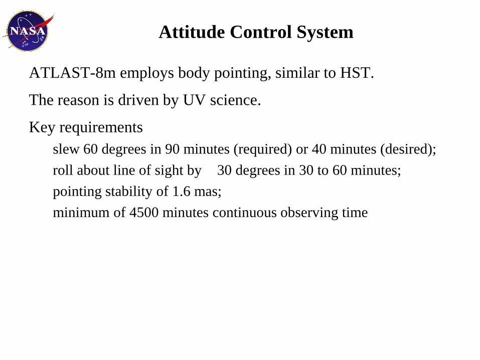
Attitude Control System
ATLAST-8m employs body pointing, similar to HST.
The reason is driven by UV science.
Key requirements
slew 60 degrees in 90 minutes (required) or 40 minutes (desired);
roll about line of sight by 30 degrees in 30 to 60 minutes;
pointing stability of 1.6 mas;
minimum of 4500 minutes continuous observing time
Attitude Control System
Star Trackers and Fine Guidance Sensors control reaction wheels
and control moment gyros to point the observatory.
Pointing is controlled using guide stars in two FGS modules
separated on the sky by 0.5 degree. This separation provides
roll control about boresight at a lower bandwidth and with
much better stability than the 0.2 mas rms requirement.
Reaction wheels provide momentum storage capability for a
minimum of 4500 minutes continuous observation time.
Active Vibration Isolation system between spacecraft and
observatory eliminate jitter to achieve sub 1.6 mas stability.

Science Observation
Two solar panels on deployable booms balance solar pressure
exerted on sunshade to achieve 6.25 days of continuous high-
precision pointing observation. By making slight adjustments
in boom length, indefinite observation times can be achieved.

Mass Budget – CBE without Margin
Since Zerodur is denser
than ULE, the most
massive possible PM is
175 mm thick Zerodur
at 25,000 kg.
Total Payload with a 175
mm Zerodur mirror is
estimated at ~50,000 kg
with 30% margin
against Ares V‟s 65 mt
to SE-L2 capacity.
ATLAST-8m Mass and Power Budget
Parameter Value Units
Mass
Optical Telescope Assembly 33,908 kg
Primary Mirror Assembly 24,988 kg
Primary Mirror 19,250 kg
Primary Mirror Mount 5,738 kg
Secondary Mirror and Aft-Optics Assemblies 2,118 kg
Structure & Other 6,802 kg
Instruments 1,789 kg
Spacecraft 4,577 kg
Propellant 4,921 kg
TOTAL PAYLOAD 45,195 kg
Launch Vehicle Payload Capacity 65,000 kg
Launch Vehicle Mass Margin (%) 44 %
Payload Mass if Primary Mirror = 25,000 kg 50,945 kg
Launch Vehicle Mass Margin 14,055 kg
Payload Mass without Primary Mirror 25.045 kg
Payload Mass Margin (%) 56 %
Spacecraft Bus Power Requirement 8,589 W
Projected End of Life Solar Panel Production 11,200 W
Solar Panel Power Margin (%) 30 %

Mission Life
Initial Mission designed for a 5 yr mission life (10 yr goal)
But, there is no reason why mission should end after 5 or 10 years
Hubble has demonstrated the value of on-orbit servicing
The telescope itself could last 30 or even 50 years
L2 Virtual Mountain Top – service & upgrade observatory robotically using AR&D (as demonstrated by Orbital Express)
Or, „propel‟ from SE-L2 to EM-L1 for Human Servicing.

Instrument to be replaced
ORU to be replaced
Servicing spacecraft
Notional Servicing Scenario
Study Results: Servicing
Replacement instrument
Replacement ORU
And so on ...

Conclusion
ATLAST Astrophysics Mission Concept Study developed a
detailed point design for an 8-m monolithic observatory:
• optical design;
• structural (primary mirror support structure, sun shade and secondary
mirror support structure);
• thermal analysis;
• spacecraft (structure, propulsion, GN&C, avionics, power systems and
reaction wheels);
• mass and power budgets; and
• cost & schedule
Complete report and responses to Decadal RFIs can be found at:
http://www.stsci.edu/institute/atlast/index_html_ATLASTMissio
nConceptStudy_Page

Any Question?