atllas d2.4.1 mdo-tool final - german aerospace center
TRANSCRIPT
AST5-CT-2006-030729
ATLLAS
Aerodynamic and Thermal Load Interactions with Lightweight Advanced Materials for High Speed Flight
SPECIFIC TARGETED RESEARCH PROJECT
Thematic Priority – 1.4 AERONAUTIC and SPACE
Deliverable Reference Number: D.2.4.1
Deliverable Title:
Report on DLR MDO tool for high-speed design
Due date of deliverable:1st of October 2008
Actual submission date: 18th of February 2009
Start date of project: 1st of October 2006
Duration: 39 months
Organisation name of lead contractor for this deliverable: DLR AS-FF (Braunschweig)
Revision #: 0
Project co-funded by the European Commission within the Sixth Framework Programme
Dissemination Level
PU Public X
PP Restricted to other programme participants (including the Commission Services)
RE Restricted to a group specified by the consortium (including the Commission Services)
CO Confidential, only for members of the consortium (including the Commission Services)

ATLLAS Del. No. D.2.4.1 MDO Tool - Page 2 of 30
APPROVAL
Title
Report on DLR MDO tool for high-speed design
issue
1
revision
0
Author(s)
Robert Dittrich
date
11.12.09
Approved by
J. Longo
T. Eggers
Date
10.12.09
15.02.10
ATLLAS Del. No. D.2.4.1 MDO Tool - Page 3 of 30
Table of contents 1 Executive summary ................................................................................................................. 6
1.1 Scope of the deliverable ..................................................................................................... 6
1.2 Results................................................................................................................................ 6
1.3 Specific highlights............................................................................................................... 7
1.4 Forms of integration within the workpackage and with other WPs ..................................... 7
1.5 Problem areas .................................................................................................................... 8
2 Introduction.............................................................................................................................. 9
3 Aspects of the MDO process................................................................................................ 11
3.1 Meaning and potential of multidisciplinary optimization.................................................... 11
3.2 Strategy, requirements and general setup ....................................................................... 11
3.3 Hypersonic propulsion integration .................................................................................... 14
4 MDO setup.............................................................................................................................. 15
4.1 Geometry generation module ........................................................................................... 15
4.2 FEM grid generation module ............................................................................................ 17
4.3 FEM computation module................................................................................................. 18
4.4 CFD grid generation module ............................................................................................ 19
4.5 CFD module ..................................................................................................................... 21
4.6 Post-processing module ................................................................................................... 22
4.7 Mission module................................................................................................................. 24
4.8 Objective function module ................................................................................................ 25
4.9 MDO environment ............................................................................................................ 27
4.10 Optimizer Environment and SUBPLEX optimizer ......................................................... 27
5 Conclusions ........................................................................................................................... 29
ATLLAS Del. No. D.2.4.1 MDO Tool - Page 4 of 30
List of Figures Fig. 3.1: General MDO process ...................................................................................................... 12
Fig. 3.2: MDA workflow types ......................................................................................................... 13
Fig. 4.1: Geometry generation process........................................................................................... 16
Fig. 4.2: FEM - model details and used materials........................................................................... 17
Fig. 4.3: Bow tank model and centre of gravity range for a given fuel mass................................... 18
Fig. 4.4: Example of lateral bending in normal modes analysis...................................................... 18
Fig. 4.5: Example of stress levels in linear static analysis .............................................................. 19
Fig. 4.6: CENTAUR modular mesh and abstraction ....................................................................... 20
Fig. 4.7: Modular mesh generation procedure for 5 meshes .......................................................... 20
Fig. 4.8: CFD Flow field characteristics .......................................................................................... 21
Fig. 4.9: Force definition for hypersonic design with “black box” combustion chamber .................. 22
Fig. 4.10 Splitting of wall domains for force definition..................................................................... 24
Fig. 4.11: Penalty function .............................................................................................................. 26
Fig. 4.12 Basic moves of NELDER-MEAD simplex method ........................................................... 28
Fig. 5.1: Final MDO process ........................................................................................................... 29
ATLLAS Del. No. D.2.4.1 MDO Tool - Page 5 of 30
Nomenclature
Acronyms
CFD Computational Fluid Dynamics
DLR DLR, German Aerospace Center (www.dlr.de)
FEA Finite Element Analysis
FEM Finite Element Method
FOI FOI, Swedish Defence Research Agency (www.foi.se)
MDA Multidisciplinary Analysis
MDO Multidisciplinary Optimization
NMS Nelder Mead Simplex method
SPP SynapsPointer Pro
ATLLAS Del. No. D.2.4.1 MDO Tool - Page 6 of 30
1 Executive summary
The presented work covers a newly developed multidisciplinary optimization (MDO) process for the preliminary design of hypersonic configurations. In generally hypersonic configurations are highly complex and integrated systems and characterized by several physical and technical problems e.g. airframe-propulsion integration, propulsion efficiency, low lift to drag ratios, high-speed versus low speed performance and strong sonic boom effects. Frequently one problem is linked to another one. Furthermore real flight data is hardly available; hence validation of design tools like numerical computations is difficult. To consider disciplinary linkages in a hypersonic design process a multidisciplinary treatment is necessary. In addition with numerical tools like CFD and FEM and the usage of massively parallel CPU power the hypersonic design process can be transformed to a multidisciplinary optimization process. Today a multidisciplinary optimization technique could provide the right platform to come closer to the realization of such kind of vehicle as is the aim to demonstrate in the present work.
Some of the featured implementations of the presented MDO process are a completely parameterized geometry generation, modular CFD grid generation, FEM based structural optimization, massively parallel CFD computations and multiple mission point analysis. Furthermore suitable data post-processing, monitoring and error handling systems are integrated.
The work includes description of requirements, constraints, the function and the setup of the MDO process. The complexity of the MDO process, the integration of involved physical disciplines and hypersonic critical issues are shown. The MDO process consists of the MDO tool and the hypersonic application whereas both are ideally decoupled. A modular setup of the MDO tool is realized for simple modifying and extension of the tool. Each module represents a specific part to perform a multidisciplinary analysis (MDA) e.g. geometry generation or CFD calculations. The MDO modules are embedded in a PYTHON based environment which takes over running and monitoring of the entire MDO process. The modules are arranged in a MDA procedure resulting in an updated objective function which is defined by the cruise range and major application constraints. By coupling the MDA procedure to a suitable optimizer the final MDO tool is formed.
The functionality of the tool is shown by applying this MDO process to the ATLLAS M6 configuration where as the cruise range is increased by 38% [9].
1.1 Scope of the deliverable
The deliverable contents:
MDO process strategy, requirements and setup Description of the integration of involved disciplines and techniques Identification of MDO relevant problems
1.2 Results
The major results of this work are:
ATLLAS Del. No. D.2.4.1 MDO Tool - Page 7 of 30
Successful development of a new MDO tool for the preliminary design of hypersonic configurations
Coupling of aerodynamic, structure and flight mechanics analyses in hypersonic conditions and with consideration of propulsion system in one tool
Multiple mission point analyses support High fidelity methods support
1.3 Specific highlights
Some specific highlights implemented into the MDO process are:
Flexible, independent and fully parameterized geometry generation Automated FEM and CFD grid generation Structural optimization within every MDO iteration High parallel CFD computing
1.4 Forms of integration within the workpackage and with other WPs
The MDO process relies on specific data of all involved physical disciplines. This data on the one side defines tool and application requirements and constraints and on the other side it determines the accuracy of the MDO process. During the project several data was provided by the ATLLAS partners:
Combustion chamber data provided by DLR-SART (WP2.4.2) Initial mission profile provided by DLR-SART (WP2.4.2) Initial mass budget based on the HYCAT-1A data provided by DLR-SART (WP2.4.2) Initial FEM modelling and analysis procedure provided by FOI (WP2.4.2) Geometry engine data (intake and dimensions) provided by ONERA (WP2.4.4) C/C-Sic material data provided by WP3 and used for leading edges (WP3.3.2) Aluminium alloy material data provided by DLR-SART and used for tank walls (WP2.4.2)
Furthermore data from the presented work was distributed to several ATLLAS partners:
Initial and optimized geometry send to several partners Aerodynamic data of ATLLAS M6 reference configuration send to DLR-SART for initial
mission analysis (WP2.4.2) Aerodynamic data of ATLLAS M6 reference and optimized configuration send to ONERA
for sonic boom analysis (WP2.1.2) Nozzle pressure distribution send to FOI for nozzle structural design (WP5.4.2)
ATLLAS Del. No. D.2.4.1 MDO Tool - Page 8 of 30
1.5 Problem areas
In this deliverable the MDO critical issues are highlighted which are time costs and functionality. The time costs are mainly driven by:
Choice of the MDO workflow type Usage and complexity of high fidelity methods e.g. CFD and FEM Choice of optimizer type Number of design parameters CPU resources
Several techniques for time reduction in the specific topics were introduced and are described within chapter 4. The functionality has to be guaranteed for the entire MDO process. A high number of possible error sources can be identified when working with different kind of software, hardware and networks where individual components have to run automatically and have to communicate with each other. Therefore a suitable error handling system was integrated into the MDO environment observing and monitoring the MDO process. Spending efforts and improving the error system was a permanently aspect during the development of the MDO tool.
ATLLAS Del. No. D.2.4.1 MDO Tool - Page 9 of 30
2 Introduction
The presented work covers a newly developed multidisciplinary optimization (MDO) process for the preliminary design of hypersonic configurations. The work is part of work package 2 “Novel concepts for high-speed flight” and is integrated in the sub work package 2.4 “Mach 6 Supersonic transport (SST) configuration”. It is not the aim of this work package to design a specific Mach 6 vehicle but to explore today’s state of the art technology limits to realize such kind of concept. The HYCAT 1A configuration [1][2] designed by Lockheed in the late 70’s provides the baseline concept for work package 2.4 and hence derived data of the HYCAT 1A is also used in this work which was provided by several ATLLAS partners.
In generally hypersonic configurations are highly complex and integrated systems and characterized by several physical and technical problems e.g. airframe-propulsion integration, propulsion efficiency, low lift to drag ratios, high-speed versus low speed performance and strong sonic boom effects. Frequently one problem is linked to another one. Furthermore real flight data is hardly available; hence validation of design tools like numerical computations is difficult. To consider disciplinary linkages in a hypersonic design process a multidisciplinary treatment is necessary. In addition with numerical tools like CFD and FEM and the usage of massively parallel CPU power the hypersonic design process can be transformed to a multidisciplinary optimization process. Today a multidisciplinary optimization technique could provide the right platform to come closer to the realization of such kind of vehicle as is the aim to demonstrate in the present work.
Due to the objective using numerical tools for the MDO process the DLR TAU code is chosen as aerodynamic flow solver. TAU is a Reynolds-averaged Navier-Stokes flow solver applicable for subsonic as well as hypersonic cases. At the beginning of the work no multidisciplinary framework using the DLR TAU code for a hypersonic MDO process existed. The implementation of a CFD code into a multidisciplinary environment requires further special methods for grid generation and data pre- and post-processing. Hence two major objectives of this work can be defined:
Development of a new MDO tool for hypersonic applications Performing of a MDO process for a given hypersonic application
In this deliverable the focus is laying on the 1st topic, however the performing of the MDO process concerning the ATLLAS Mach 6 configuration is described more precisely in deliverable 2.4.2 [9]. Although the presented work tries to give a more general description of the developed MDO tool for hypersonic applications at certain points there will be always a direct connection to the MDO process of the ATLLAS Mach 6 configuration. This is due to the fact that a MDO process is very complex process whereas at the moment a complete separation between the tool and the application is not possible.
The development of the MDO tool consists of the formulation of the optimization problem as well as realization to solve this formulation. In a preliminary aircraft design the cruise range is a first approach to describe the configuration performance. Thus the optimization objective was fixed very early in the ATLLAS project. The next step is the consideration and integration of the involved physical disciplines which are at the moment:
Aerodynamics Structure mechanics Propulsion Flight mechanics

ATLLAS Del. No. D.2.4.1 MDO Tool - Page 10 of 30
Hypersonic critical issues like propulsion integration are pointed out as well as the modular concept of the MDO tool. MDO modules represent one major aspect of the entire process e.g. geometry generation or CFD calculations. The modular concept allows simple adding, removing and modifying of certain modules; hence the MDO process can be adapted to a specific application and its requirements. Furthermore in addition to the usage of high-fidelity tools, the consideration of multiple mission points of a hypersonic trajectory is targeted in the presented work.
ATLLAS Del. No. D.2.4.1 MDO Tool - Page 11 of 30
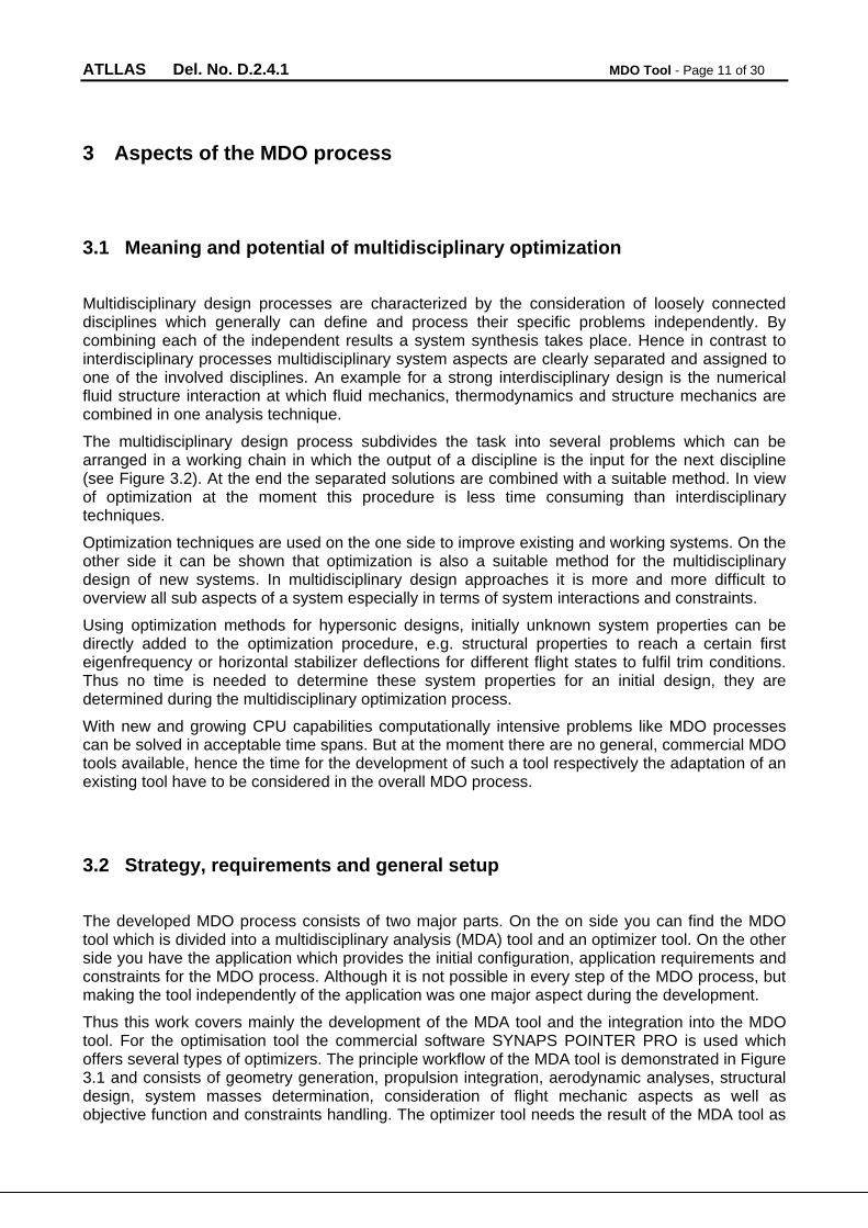
3 Aspects of the MDO process
3.1 Meaning and potential of multidisciplinary optimization
Multidisciplinary design processes are characterized by the consideration of loosely connected disciplines which generally can define and process their specific problems independently. By combining each of the independent results a system synthesis takes place. Hence in contrast to interdisciplinary processes multidisciplinary system aspects are clearly separated and assigned to one of the involved disciplines. An example for a strong interdisciplinary design is the numerical fluid structure interaction at which fluid mechanics, thermodynamics and structure mechanics are combined in one analysis technique.
The multidisciplinary design process subdivides the task into several problems which can be arranged in a working chain in which the output of a discipline is the input for the next discipline (see Figure 3.2). At the end the separated solutions are combined with a suitable method. In view of optimization at the moment this procedure is less time consuming than interdisciplinary techniques.
Optimization techniques are used on the one side to improve existing and working systems. On the other side it can be shown that optimization is also a suitable method for the multidisciplinary design of new systems. In multidisciplinary design approaches it is more and more difficult to overview all sub aspects of a system especially in terms of system interactions and constraints.
Using optimization methods for hypersonic designs, initially unknown system properties can be directly added to the optimization procedure, e.g. structural properties to reach a certain first eigenfrequency or horizontal stabilizer deflections for different flight states to fulfil trim conditions. Thus no time is needed to determine these system properties for an initial design, they are determined during the multidisciplinary optimization process.
With new and growing CPU capabilities computationally intensive problems like MDO processes can be solved in acceptable time spans. But at the moment there are no general, commercial MDO tools available, hence the time for the development of such a tool respectively the adaptation of an existing tool have to be considered in the overall MDO process.
3.2 Strategy, requirements and general setup
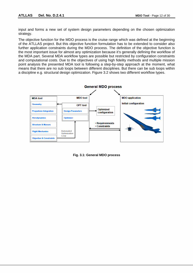
The developed MDO process consists of two major parts. On the on side you can find the MDO tool which is divided into a multidisciplinary analysis (MDA) tool and an optimizer tool. On the other side you have the application which provides the initial configuration, application requirements and constraints for the MDO process. Although it is not possible in every step of the MDO process, but making the tool independently of the application was one major aspect during the development.
Thus this work covers mainly the development of the MDA tool and the integration into the MDO tool. For the optimisation tool the commercial software SYNAPS POINTER PRO is used which offers several types of optimizers. The principle workflow of the MDA tool is demonstrated in Figure 3.1 and consists of geometry generation, propulsion integration, aerodynamic analyses, structural design, system masses determination, consideration of flight mechanic aspects as well as objective function and constraints handling. The optimizer tool needs the result of the MDA tool as
ATLLAS Del. No. D.2.4.1 MDO Tool - Page 12 of 30
input and forms a new set of system design parameters depending on the chosen optimization strategy.
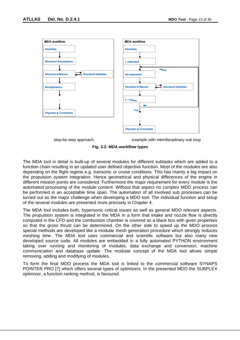
The objective function for the MDO process is the cruise range which was defined at the beginning of the ATLLAS project. But this objective function formulation has to be extended to consider also further application constraints during the MDO process. The definition of the objective function is the most important issue for almost any optimization because it’s generally defining the workflow of the MDA part. Several MDA workflow types are possible but restricted by configuration constraints and computational costs. Due to the objectives of using high fidelity methods and multiple mission point analysis the presented MDA tool is following a step-by-step approach at the moment, what means that there are no sub loops between different disciplines. But there can be sub loops within a discipline e.g. structural design optimization. Figure 3.2 shows two different workflow types.
Fig. 3.1: General MDO process
ATLLAS Del. No. D.2.4.1 MDO Tool - Page 13 of 30
step-by-step approach example with interdisciplinary sub loop
Fig. 3.2: MDA workflow types
The MDA tool in detail is built-up of several modules for different subtasks which are added to a function chain resulting in an updated user defined objective function. Most of the modules are also depending on the flight regime e.g. transonic or cruise conditions. This has mainly a big impact on the propulsion system integration. Hence geometrical and physical differences of the engine in different mission points are considered. Furthermore the major requirement for every module is the automated processing of the module content. Without that aspect no complex MDO process can be performed in an acceptable time span. The automation of all involved sub processes can be turned out as the major challenge when developing a MDO tool. The individual function and setup of the several modules are presented more precisely in Chapter 4.
The MDA tool includes both, hypersonic critical issues as well as general MDO relevant aspects. The propulsion system is integrated in the MDA in a form that intake and nozzle flow is directly computed in the CFD and the combustion chamber is covered as a black box with given properties so that the gross thrust can be determined. On the other side to speed up the MDO process special methods are developed like a modular mesh generation procedure which strongly reduces meshing time. The MDA tool uses commercial and scientific software but also many new developed source code. All modules are embedded in a fully automated PYTHON environment taking over running and monitoring of modules, data exchange and conversion, machine communication and database update. The modular concept of the MDA tool allows simple removing, adding and modifying of modules.
To form the final MDO process the MDA tool is linked to the commercial software SYNAPS POINTER PRO [7] which offers several types of optimizers. In the presented MDO the SUBPLEX optimizer, a function ranking method, is favoured.
ATLLAS Del. No. D.2.4.1 MDO Tool - Page 14 of 30
3.3 Hypersonic propulsion integration
One of the objectives of this work is the integration of the hypersonic propulsion system to the MDO process. Unlike other disciplines the propulsion can not be covered as a separate module because it is affecting several parts of the MDO process, especially geometry generation, CFD computations and force calculations. In generally the propulsion system is an application aspect, but due to the big impact of the propulsion of hypersonic configurations to the overall performance it is also an important aspect of the MDO tool itself.
The background for the propulsion system of the ATLLAS M6 configuration is given by some initial geometrical data of the HYCAT 1A configuration and a combustion chamber data set depending on flight Mach number and throttle level which was provided by DLR-SART. During the ATLLAS project the engine geometry was updated by ATLLAS partner ONERA and integrated to the MDO process. Hence engine geometry data for hypersonic intake shape and engine cover was available where as both are not affected by the MDO process. In contrast the nozzle design was first derived by the HYCAT 1A, but four nozzle parameters were chosen for the optimization design parameter set.
The provided combustion chamber data set contains flow data for total pressure, total temperature, mass flow etc. for the combustion chamber inlet and outlet respectively nozzle throat area where the Mach number is always set to 1. The two unknown flow values are the inlet Mach number and inlet throat area. The inlet Mach number is assumed to be 0.7 hence the inlet throat area can be calculated. With this data the gross thrust for the combustion chamber can be determined for every throttle level by applying the principle of linear momentum.
Concerning the CFD calculations inlet and outlet boundary conditions are used and limiting the CFD domain. Here the nozzle throat area is an active boundary condition where flow values depending on the current throttle level are set. Against what the combustion chamber inlet is a passive boundary condition (outlet condition) whereas the flow values are monitored. For the transonic flight point an engine bypass channel model for drag reduction is integrated to the MDO process. This model simulates that a certain amount of incoming air mass flow can flow through the bypass channel. In CFD computations the boundary conditions are covered exactly in the same way described above. 2D NAVIER-STOKES computations were performed to determine the bypass outlet conditions which afterwards are used in the 3D computations. Without this bypass model the thrust produced at 100% throttle was always smaller than the drag for all transonic CFD computations. Furthermore due to unknown throttle levels for simulating steady horizontal flight condition for different Mach numbers and configuration states an interpolation routine is introduced to the MDO process. These modifications are important and necessary to describe the configuration performance more accurate, but also the level of complexity and the computational costs of the MDO process are strongly increased.
ATLLAS Del. No. D.2.4.1 MDO Tool - Page 15 of 30
4 MDO setup
In the following sections an overview of the several MDA modules is presented. The function and realisation of each module as well as the linkage among each other is shown. The modules are integrated into a MDO environment. Additionally a short overview about the optimizer environment SYNAPSPOINTER PRO and the used SUBPLEX optimizer is given at the end of this chapter.
4.1 Geometry generation module
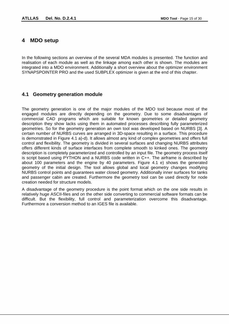
The geometry generation is one of the major modules of the MDO tool because most of the engaged modules are directly depending on the geometry. Due to some disadvantages of commercial CAD programs which are suitable for known geometries or detailed geometry description they show lacks using them in automated processes describing fully parameterized geometries. So for the geometry generation an own tool was developed based on NURBS [3]. A certain number of NURBS curves are arranged in 3D-space resulting in a surface. This procedure is demonstrated in Figure 4.1 a)-d). It allows almost any kind of complex geometries and offers full control and flexibility. The geometry is divided in several surfaces and changing NURBS attributes offers different kinds of surface interfaces from complete smooth to kinked ones. The geometry description is completely parameterized and controlled by an input file. The geometry process itself is script based using PYTHON and a NURBS code written in C++. The airframe is described by about 100 parameters and the engine by 40 parameters. Figure 4.1 e) shows the generated geometry of the initial design. The tool allows global and local geometry changes modifying NURBS control points and guarantees water closed geometry. Additionally inner surfaces for tanks and passenger cabin are created. Furthermore the geometry tool can be used directly for node creation needed for structure models.
A disadvantage of the geometry procedure is the point format which on the one side results in relatively huge ASCII-files and on the other side converting to commercial software formats can be difficult. But the flexibility, full control and parameterization overcome this disadvantage. Furthermore a conversion method to an IGES file is available.
ATLLAS Del. No. D.2.4.1 MDO Tool - Page 16 of 30
a) 3 sets of 4 control points b) Control curves formed by control points
c) Final NURBS curves formed by control curves d) Final NURBS curves interpreted as surface
e) Initial ATLLAS M6 geometry created by the geometry generation module
Fig. 4.1: Geometry generation process
ATLLAS Del. No. D.2.4.1 MDO Tool - Page 17 of 30
4.2 FEM grid generation module
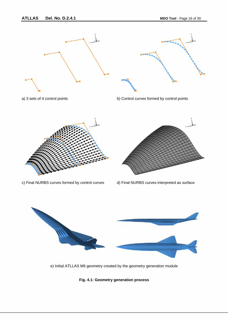
For FEM computations a PYTHON script based grid generation procedure is developed based on the outer geometry which is given by the geometry generation module. This procedure is embedded in an independent module. First the geometry is divided in major parts e.g. fuselage, wings, engine etc. These parts are then divided in a certain number of cross sections presenting the FEM model outer nodes. Accordingly inner nodes are added describing vertices of tanks, walls and frame stations. After grid node description FEM elements like shells, bars and rigid body elements for node coupling are created. Material properties were given by FOI and applied to specified property groups. Non-structural masses given by an initial mass budget are connected to grid nodes using concentrated mass elements which are distributed over the whole geometry.
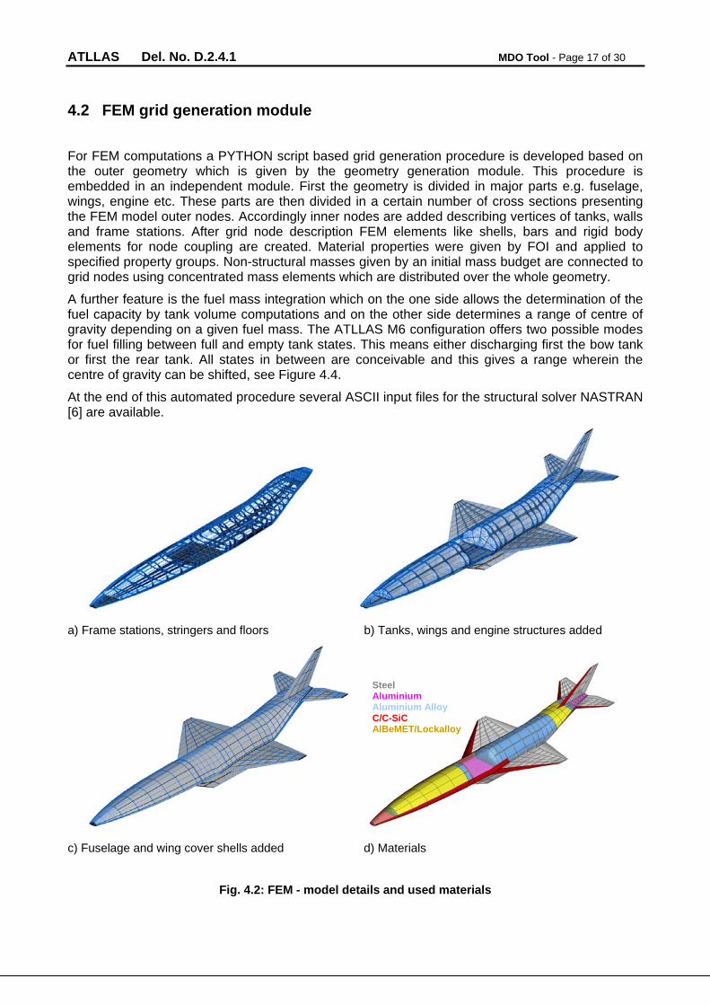
A further feature is the fuel mass integration which on the one side allows the determination of the fuel capacity by tank volume computations and on the other side determines a range of centre of gravity depending on a given fuel mass. The ATLLAS M6 configuration offers two possible modes for fuel filling between full and empty tank states. This means either discharging first the bow tank or first the rear tank. All states in between are conceivable and this gives a range wherein the centre of gravity can be shifted, see Figure 4.4.
At the end of this automated procedure several ASCII input files for the structural solver NASTRAN [6] are available.
a) Frame stations, stringers and floors b) Tanks, wings and engine structures added
c) Fuselage and wing cover shells added d) Materials
Fig. 4.2: FEM - model details and used materials
Steel Aluminium Aluminium Alloy C/C-SiC AlBeMET/Lockalloy
ATLLAS Del. No. D.2.4.1 MDO Tool - Page 18 of 30
Fig. 4.3: Bow tank model and centre of gravity range for a given fuel mass
4.3 FEM computation module
For FEM computations the structural solver NASTRAN [6] is used with the main function of sizing the structure for every configuration during the MDO process. Therefore oversized, initial element properties are applied to the FEM model and using the NASTRAN internal optimizer lead to a structural weight minimized configuration whereas almost 200 structural parameters are used.
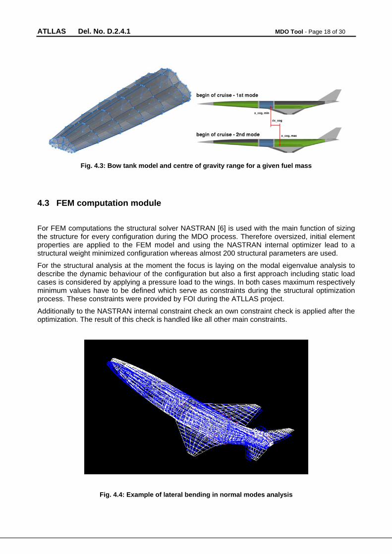
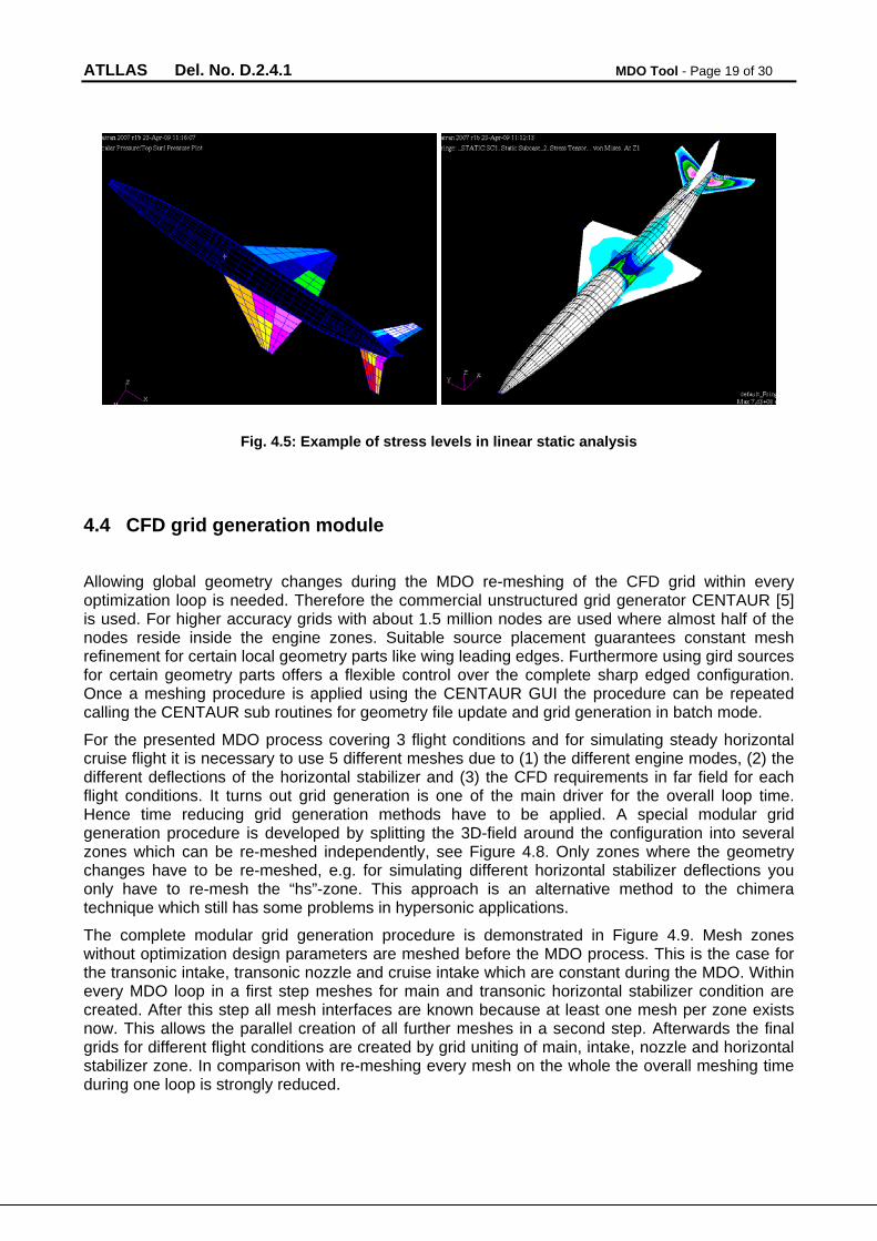
For the structural analysis at the moment the focus is laying on the modal eigenvalue analysis to describe the dynamic behaviour of the configuration but also a first approach including static load cases is considered by applying a pressure load to the wings. In both cases maximum respectively minimum values have to be defined which serve as constraints during the structural optimization process. These constraints were provided by FOI during the ATLLAS project.
Additionally to the NASTRAN internal constraint check an own constraint check is applied after the optimization. The result of this check is handled like all other main constraints.
Fig. 4.4: Example of lateral bending in normal modes analysis
ATLLAS Del. No. D.2.4.1 MDO Tool - Page 19 of 30
Fig. 4.5: Example of stress levels in linear static analysis
4.4 CFD grid generation module
Allowing global geometry changes during the MDO re-meshing of the CFD grid within every optimization loop is needed. Therefore the commercial unstructured grid generator CENTAUR [5] is used. For higher accuracy grids with about 1.5 million nodes are used where almost half of the nodes reside inside the engine zones. Suitable source placement guarantees constant mesh refinement for certain local geometry parts like wing leading edges. Furthermore using gird sources for certain geometry parts offers a flexible control over the complete sharp edged configuration. Once a meshing procedure is applied using the CENTAUR GUI the procedure can be repeated calling the CENTAUR sub routines for geometry file update and grid generation in batch mode.
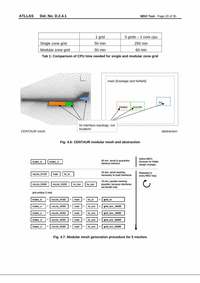
For the presented MDO process covering 3 flight conditions and for simulating steady horizontal cruise flight it is necessary to use 5 different meshes due to (1) the different engine modes, (2) the different deflections of the horizontal stabilizer and (3) the CFD requirements in far field for each flight conditions. It turns out grid generation is one of the main driver for the overall loop time. Hence time reducing grid generation methods have to be applied. A special modular grid generation procedure is developed by splitting the 3D-field around the configuration into several zones which can be re-meshed independently, see Figure 4.8. Only zones where the geometry changes have to be re-meshed, e.g. for simulating different horizontal stabilizer deflections you only have to re-mesh the “hs”-zone. This approach is an alternative method to the chimera technique which still has some problems in hypersonic applications.
The complete modular grid generation procedure is demonstrated in Figure 4.9. Mesh zones without optimization design parameters are meshed before the MDO process. This is the case for the transonic intake, transonic nozzle and cruise intake which are constant during the MDO. Within every MDO loop in a first step meshes for main and transonic horizontal stabilizer condition are created. After this step all mesh interfaces are known because at least one mesh per zone exists now. This allows the parallel creation of all further meshes in a second step. Afterwards the final grids for different flight conditions are created by grid uniting of main, intake, nozzle and horizontal stabilizer zone. In comparison with re-meshing every mesh on the whole the overall meshing time during one loop is strongly reduced.
ATLLAS Del. No. D.2.4.1 MDO Tool - Page 20 of 30
1 grid 5 grids – 1 core cpu
Single zone grid 50 min 250 min
Modular zone grid 50 min 60 min
Tab 1: Comparison of CPU time needed for single and modular zone grid
Fig. 4.6: CENTAUR modular mesh and abstraction
Fig. 4.7: Modular mesh generation procedure for 5 meshes
main (fuselage and farfield)
intake nozzle
hs
CENTAUR mesh abstraction
fix interface topology, not location!
ATLLAS Del. No. D.2.4.1 MDO Tool - Page 21 of 30
4.5 CFD module
The CFD module numeric flow calculations are performed using the DLR TAU code [8], a Reynolds-averaged Navier-Stokes flow solver applicable for subsonic as well as hypersonic cases. For reducing flow solver time TAU is running in Euler mode in addition with large parallel computing. Due to the main interest is the global output of the calculations like the pressure distribution and the force coefficients the calculations are performed on the sharp edged model. But this approach would introduce errors in heatflux or temperature determinations near the sharp leading edges of viscid calculations.
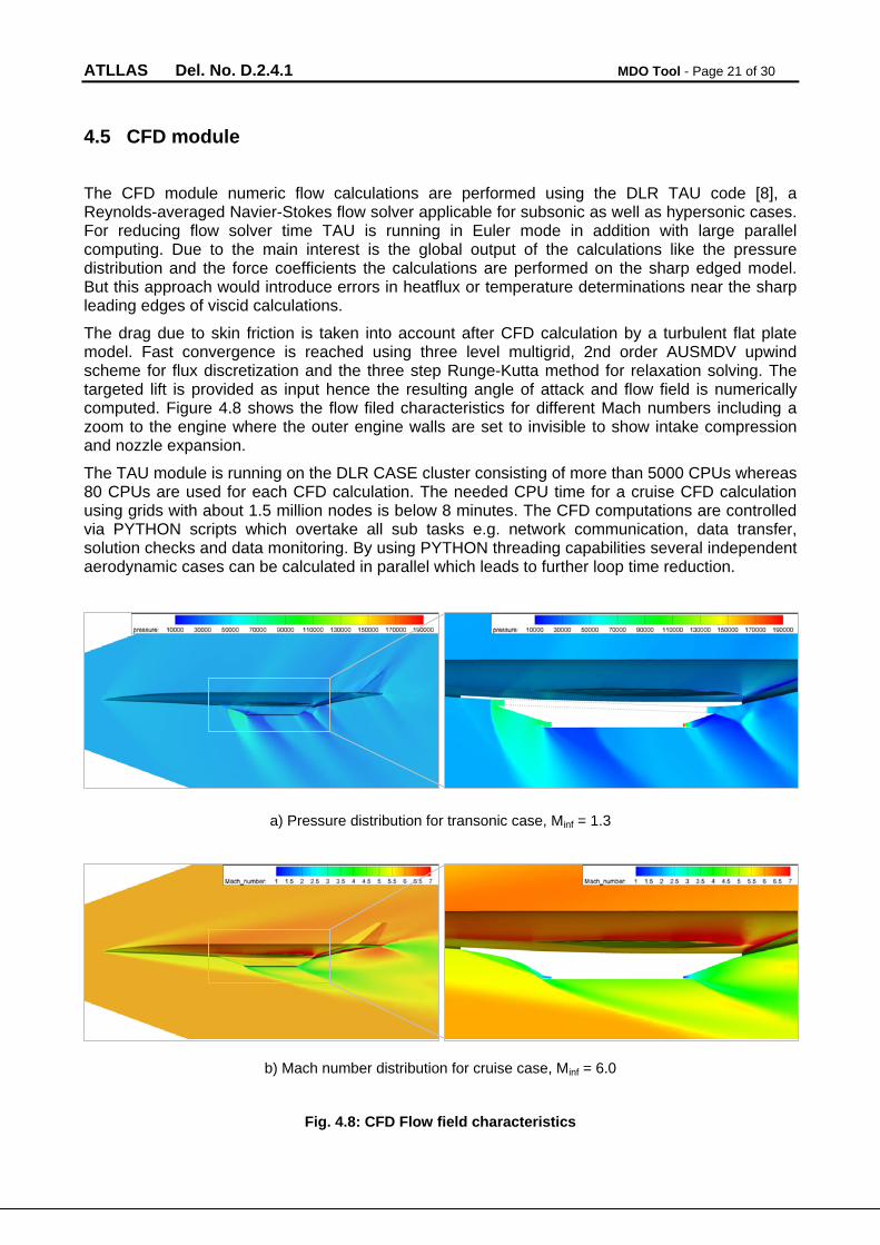
The drag due to skin friction is taken into account after CFD calculation by a turbulent flat plate model. Fast convergence is reached using three level multigrid, 2nd order AUSMDV upwind scheme for flux discretization and the three step Runge-Kutta method for relaxation solving. The targeted lift is provided as input hence the resulting angle of attack and flow field is numerically computed. Figure 4.8 shows the flow filed characteristics for different Mach numbers including a zoom to the engine where the outer engine walls are set to invisible to show intake compression and nozzle expansion.
The TAU module is running on the DLR CASE cluster consisting of more than 5000 CPUs whereas 80 CPUs are used for each CFD calculation. The needed CPU time for a cruise CFD calculation using grids with about 1.5 million nodes is below 8 minutes. The CFD computations are controlled via PYTHON scripts which overtake all sub tasks e.g. network communication, data transfer, solution checks and data monitoring. By using PYTHON threading capabilities several independent aerodynamic cases can be calculated in parallel which leads to further loop time reduction.
a) Pressure distribution for transonic case, Minf = 1.3
b) Mach number distribution for cruise case, Minf = 6.0
Fig. 4.8: CFD Flow field characteristics
ATLLAS Del. No. D.2.4.1 MDO Tool - Page 22 of 30
4.6 Post-processing module
The post-processing module contains all information and formulations concerning force, moment and trim capability determinations.
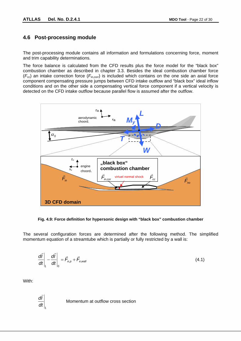
The force balance is calculated from the CFD results plus the force model for the “black box” combustion chamber as described in chapter 3.3. Besides the ideal combustion chamber force (Fcc) an intake correction force (Fin,corr) is included which contains on the one side an axial force component compensating pressure jumps between CFD intake outflow and “black box” ideal inflow conditions and on the other side a compensating vertical force component if a vertical velocity is detected on the CFD intake outflow because parallel flow is assumed after the outflow.
Fig. 4.9: Force definition for hypersonic design with “black box” combustion chamber
The several configuration forces are determined after the following method. The simplified momentum equation of a streamtube which is partially or fully restricted by a wall is:
wallepe FFdt
Id
dt
Id,,
01
(4.1)
With:
1
dt
Id
Momentum at outflow cross section
inF
corinF ,
ccF
noF
3D CFD domain
„black box“ combustion chamber virtuel normal shock
xe
ze
engine
choord.
aerodynamic choord.
za
xa
L
D
T
W
0
My
ATLLAS Del. No. D.2.4.1 MDO Tool - Page 23 of 30
0
dt
Id
Momentum at inflow cross section
peF ,
External pressure force
walleF ,
External wall force
By considering the principle of reaction the resulting force on the wall is:
wallewall FF ,
(4.2)
Hence the wall force is the reaction of any changes in flow velocity, flow direction and streamtube cross section area. The wall force is computed numerically and for an inviscid flow on a discretized surface it is determined by:
ii
iwall nppF
(4.3)
With:
ip Pressure on cell i
p Ambient pressure
in
Normal vector of cell i
Accordingly the wall force is generally divided in a lift and a drag component. Due to the consideration of intake and nozzle flow in CFD (see Figure 4.8 and Figure 4.9) the global wall force also includes parts of the net thrust. Hence a suitable force definition has to be applied to split up the forces to the classical description of lift, drag, thrust and weight. In the presented work the configuration forces are defined as:
xanoxainCFDconfig FFDD ,, (4.4)
zacczacorrinCFDconfig FFLL ,,, (4.5)
xanoxainxacorrinxaccconfig FFFFT ,,,,, (4.6)
The drag components of the intake and nozzle forces are subtracted from the overall CFD drag resulting in the configuration drag. These subtracted forces are added to the drag components of the intake correction and combustion chamber force which defines the net thrust. Finally the sum of all lift components gives the final configuration lift. The intake and nozzle forces are determined by splitting the global wall surface into smaller sub-surfaces and assign each sub-surface either to the intake, the nozzle or the main wall. These method can be applied due to the complete pressure distribution on the wall is known after the CFD calculation. The surface splitting is similar to the
ATLLAS Del. No. D.2.4.1 MDO Tool - Page 24 of 30
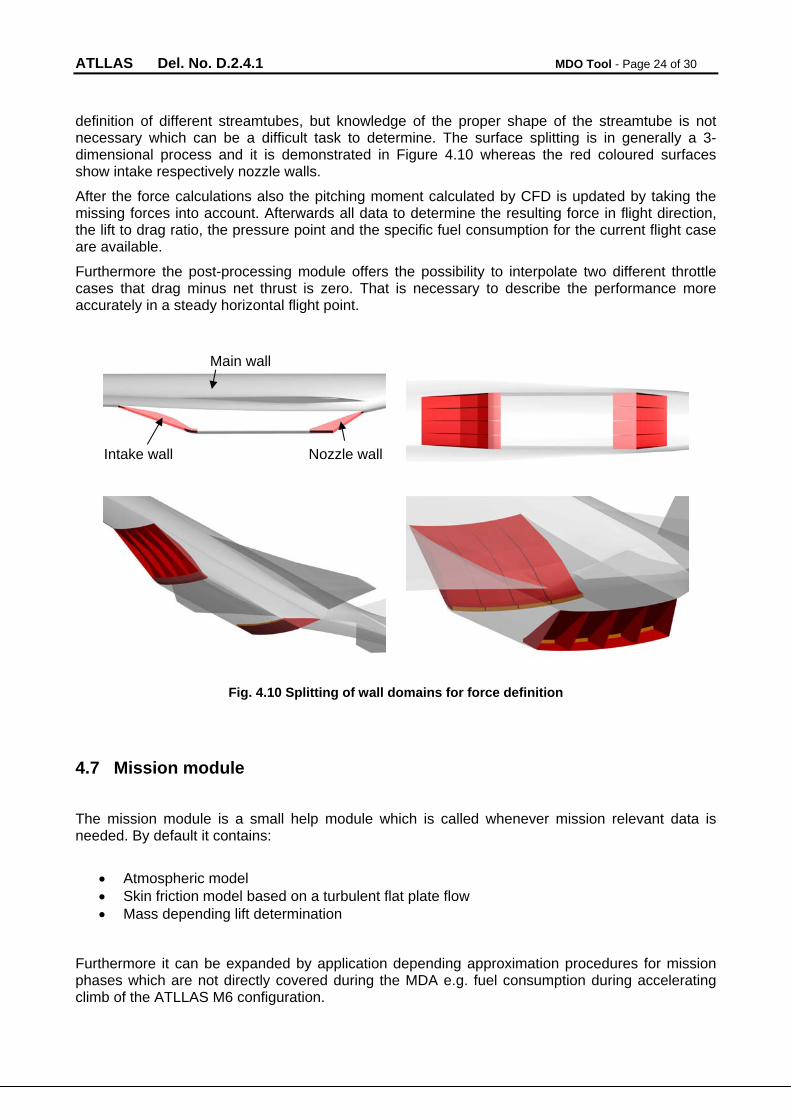
definition of different streamtubes, but knowledge of the proper shape of the streamtube is not necessary which can be a difficult task to determine. The surface splitting is in generally a 3-dimensional process and it is demonstrated in Figure 4.10 whereas the red coloured surfaces show intake respectively nozzle walls.
After the force calculations also the pitching moment calculated by CFD is updated by taking the missing forces into account. Afterwards all data to determine the resulting force in flight direction, the lift to drag ratio, the pressure point and the specific fuel consumption for the current flight case are available.
Furthermore the post-processing module offers the possibility to interpolate two different throttle cases that drag minus net thrust is zero. That is necessary to describe the performance more accurately in a steady horizontal flight point.
Fig. 4.10 Splitting of wall domains for force definition
4.7 Mission module
The mission module is a small help module which is called whenever mission relevant data is needed. By default it contains:
Atmospheric model Skin friction model based on a turbulent flat plate flow Mass depending lift determination
Furthermore it can be expanded by application depending approximation procedures for mission phases which are not directly covered during the MDA e.g. fuel consumption during accelerating climb of the ATLLAS M6 configuration.
Intake wall Nozzle wall
Main wall
ATLLAS Del. No. D.2.4.1 MDO Tool - Page 25 of 30
4.8 Objective function module
The definition of the objective function is the most important part of the MDO process because it is driving the MDO characteristics. It can have a big impact of the overall design of the MDO process. The objective function has to combine all aspects of the application of the MDO where as at the end in generally only one value describing the performance of the application.
Although there are some disadvantages the BREGUET range is a widely accepted method to describe the cruise range as performance of aircrafts. Hence the BREGUET range is also used in the presented MDO. It directly couples aerodynamic and propulsion performance as well as configuration mass ratio. It is defined by:
eoc
boc
crcr
crB m
m
D
L
sfc
vR ln (4.7)
Where as:
BR Breguet range
crv Cruise velocity
crsfc Cruise specific fuel consumption
crD
L Cruise lift to drag ration
bocm Begin of cruise mass
eocm End of cruise mass
One of the disadvantages of the BREGUET range is the fact that it only takes the begin of cruise flight point into account which is suitable for subsonic aircrafts. It is assumed that lift, lift to drag ratio and specific fuel consumption is constant during cruise resulting in a climbing cruise. During the ATLLAS project it was shown that there is a need to change the horizontal stabilizer deflection during the cruise of the Mach 6 configuration due to trim. This of course has an impact of the aerodynamic and engine performance which cannot be considered using the default BREGEUT equation. Hence the BREGEUT equation is used with mean values for the lift to drag ratio and specific fuel consumption of the begin of cruise and end of cruise point:
eoc
boc
mcrmcr
crB m
m
D
L
sfc
vR ln
,,
(4.8)
Application constraints which can not be found in the range equation formulate a constrained optimization problem. The favoured method to handle constraints in the presented MDO is the integration of a penalty function to the range equation which gives the final objective function described by:
ATLLAS Del. No. D.2.4.1 MDO Tool - Page 26 of 30
pR
ROF
ref
curr 1 (4.9)
With:
ipp 0.1 (4.10)
Where as:
OF Objective function
currR Range current configuration
refR Reference range
p Penalty function
ip Penalty function of constraint i
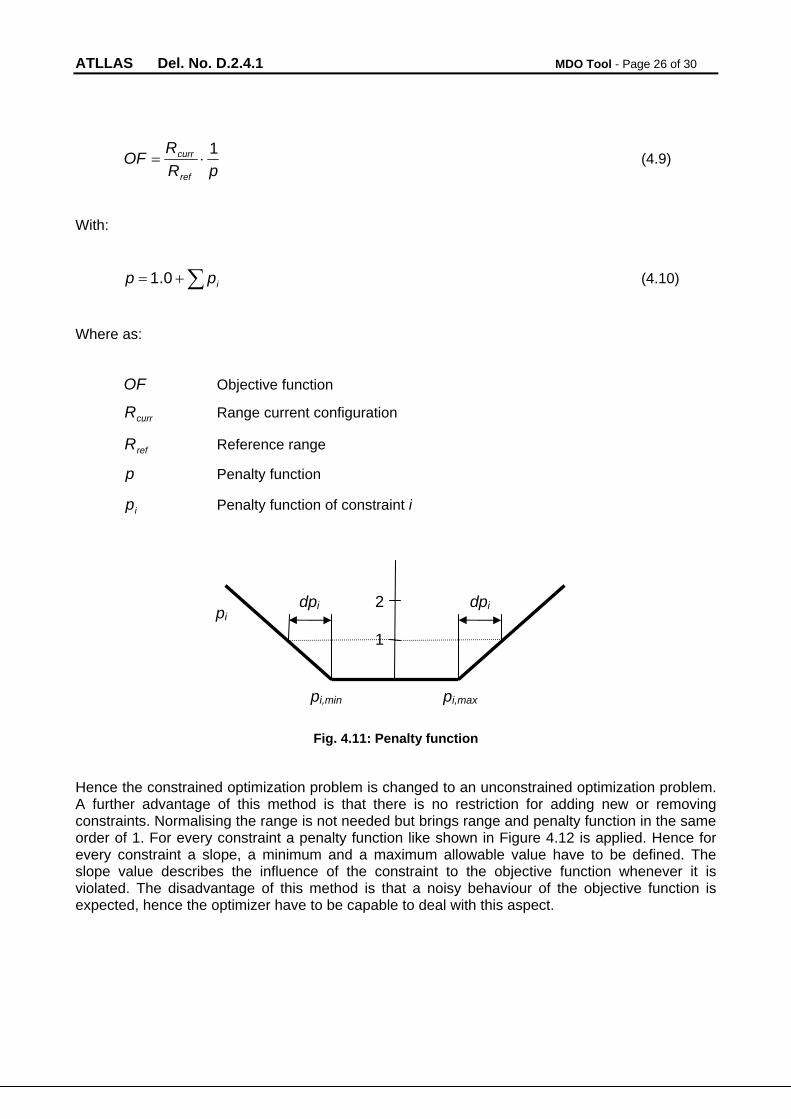
Fig. 4.11: Penalty function
Hence the constrained optimization problem is changed to an unconstrained optimization problem. A further advantage of this method is that there is no restriction for adding new or removing constraints. Normalising the range is not needed but brings range and penalty function in the same order of 1. For every constraint a penalty function like shown in Figure 4.12 is applied. Hence for every constraint a slope, a minimum and a maximum allowable value have to be defined. The slope value describes the influence of the constraint to the objective function whenever it is violated. The disadvantage of this method is that a noisy behaviour of the objective function is expected, hence the optimizer have to be capable to deal with this aspect.
1
2 pi
pi,min pi,max
dpi dpi
ATLLAS Del. No. D.2.4.1 MDO Tool - Page 27 of 30
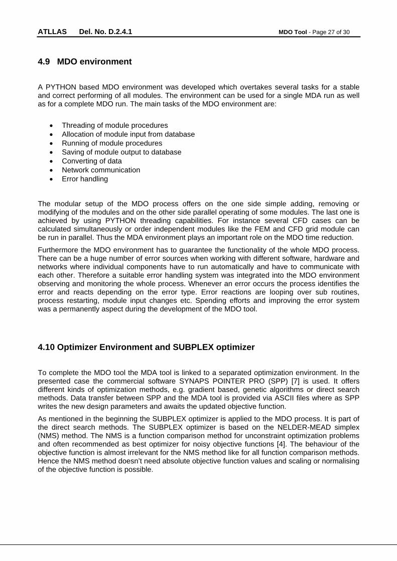
4.9 MDO environment
A PYTHON based MDO environment was developed which overtakes several tasks for a stable and correct performing of all modules. The environment can be used for a single MDA run as well as for a complete MDO run. The main tasks of the MDO environment are:
Threading of module procedures Allocation of module input from database Running of module procedures Saving of module output to database Converting of data Network communication Error handling
The modular setup of the MDO process offers on the one side simple adding, removing or modifying of the modules and on the other side parallel operating of some modules. The last one is achieved by using PYTHON threading capabilities. For instance several CFD cases can be calculated simultaneously or order independent modules like the FEM and CFD grid module can be run in parallel. Thus the MDA environment plays an important role on the MDO time reduction.
Furthermore the MDO environment has to guarantee the functionality of the whole MDO process. There can be a huge number of error sources when working with different software, hardware and networks where individual components have to run automatically and have to communicate with each other. Therefore a suitable error handling system was integrated into the MDO environment observing and monitoring the whole process. Whenever an error occurs the process identifies the error and reacts depending on the error type. Error reactions are looping over sub routines, process restarting, module input changes etc. Spending efforts and improving the error system was a permanently aspect during the development of the MDO tool.
4.10 Optimizer Environment and SUBPLEX optimizer
To complete the MDO tool the MDA tool is linked to a separated optimization environment. In the presented case the commercial software SYNAPS POINTER PRO (SPP) [7] is used. It offers different kinds of optimization methods, e.g. gradient based, genetic algorithms or direct search methods. Data transfer between SPP and the MDA tool is provided via ASCII files where as SPP writes the new design parameters and awaits the updated objective function.
As mentioned in the beginning the SUBPLEX optimizer is applied to the MDO process. It is part of the direct search methods. The SUBPLEX optimizer is based on the NELDER-MEAD simplex (NMS) method. The NMS is a function comparison method for unconstraint optimization problems and often recommended as best optimizer for noisy objective functions [4]. The behaviour of the objective function is almost irrelevant for the NMS method like for all function comparison methods. Hence the NMS method doesn’t need absolute objective function values and scaling or normalising of the objective function is possible.
ATLLAS Del. No. D.2.4.1 MDO Tool - Page 28 of 30
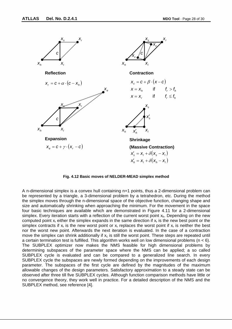
Fig. 4.12 Basic moves of NELDER-MEAD simplex method
A n-dimensional simplex is a convex hull containing n+1 points, thus a 2-dimensional problem can be represented by a triangle, a 3-dimensional problem by a tetrahedron, etc. During the method the simplex moves through the n-dimensional space of the objective function, changing shape and size and automatically shrinking when approaching the minimum. For the movement in the space four basic techniques are available which are demonstrated in Figure 4.11 for a 2-dimensional simplex. Every iteration starts with a reflection of the current worst point xh. Depending on the new computed point xr either the simplex expands in the same direction if xr is the new best point or the simplex contracts if xr is the new worst point or xr replaces the worst point if xr is neither the best nor the worst new point. Afterwards the next iteration is evaluated. In the case of a contraction move the simplex can shrink additionally if xc is still the worst point. These steps are repeated until a certain termination test is fulfilled. This algorithm works well on low dimensional problems (n < 6). The SUBPLEX optimizer now makes the NMS feasible for high dimensional problems by determining subspaces of the parameter space where the NMS can be applied; a so called SUBPLEX cycle is evaluated and can be compared to a generalized line search. In every SUBPLEX cycle the subspaces are newly formed depending on the improvements of each design parameter. The subspaces of the first cycle are defined by the magnitudes of the maximum allowable changes of the design parameters. Satisfactory approximation to a steady state can be observed after three till five SUBPLEX cycles. Although function comparison methods have little or no convergence theory, they work well in practice. For a detailed description of the NMS and the SUBPLEX method, see reference [4].
Reflection
hr xccx
c
rx
hx
sx
lx
Expansion
cxcx re
c
rxsx
lx
Contraction
hrr
hrh
c
ffxx
ffxx
cxcx
if
if
c
rxsx
lx
Shrinkage
(Massive Contraction)
sx
sx
lxhxhx
hx
ex
cx
cx
lhlh
lsls
xxxx
xxxx
hx
ATLLAS Del. No. D.2.4.1 MDO Tool - Page 29 of 30
5 Conclusions
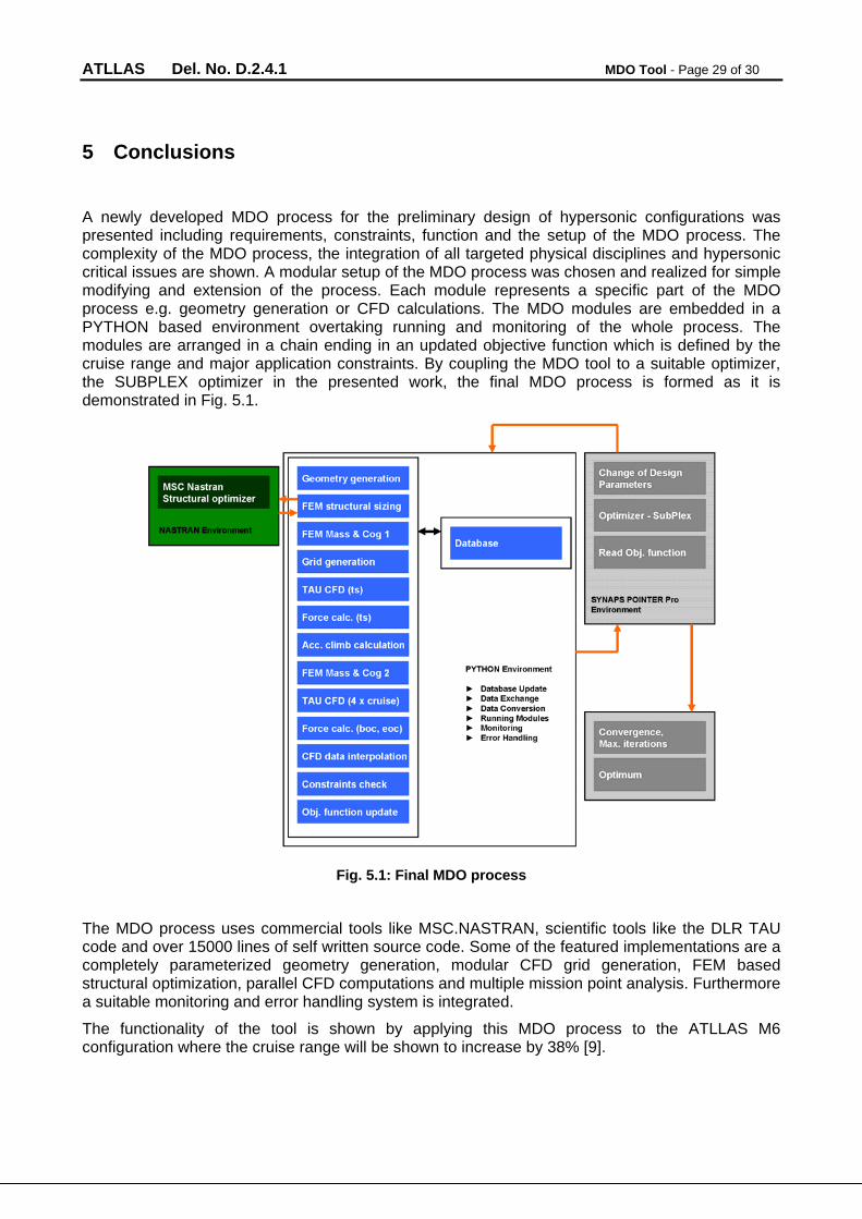
A newly developed MDO process for the preliminary design of hypersonic configurations was presented including requirements, constraints, function and the setup of the MDO process. The complexity of the MDO process, the integration of all targeted physical disciplines and hypersonic critical issues are shown. A modular setup of the MDO process was chosen and realized for simple modifying and extension of the process. Each module represents a specific part of the MDO process e.g. geometry generation or CFD calculations. The MDO modules are embedded in a PYTHON based environment overtaking running and monitoring of the whole process. The modules are arranged in a chain ending in an updated objective function which is defined by the cruise range and major application constraints. By coupling the MDO tool to a suitable optimizer, the SUBPLEX optimizer in the presented work, the final MDO process is formed as it is demonstrated in Fig. 5.1.
Fig. 5.1: Final MDO process
The MDO process uses commercial tools like MSC.NASTRAN, scientific tools like the DLR TAU code and over 15000 lines of self written source code. Some of the featured implementations are a completely parameterized geometry generation, modular CFD grid generation, FEM based structural optimization, parallel CFD computations and multiple mission point analysis. Furthermore a suitable monitoring and error handling system is integrated.
The functionality of the tool is shown by applying this MDO process to the ATLLAS M6 configuration where the cruise range will be shown to increase by 38% [9].
ATLLAS Del. No. D.2.4.1 MDO Tool - Page 30 of 30
References
[1] G.D. Brewer, R.E. Morris, “Hypersonic Cruise Aircraft Propulsion Integration Study Volume I/II”, NASA Contractor Report, CR-158926-1 – 1979
[2] J.C. Ellison, “Investigation of the Aerodynamic Characteristics of a Hypersonic Transport Model at Mach Numbers up to 6”, NASA Technical Note D-6191 – 1971
[3] L. Piegl, “The NURBS Book””, 2nd Edition, Springer – 1997
[4] T. Rowan, “Functional Stability of Numerical Algorithms”, Thesis, Department of Computer Sciences, University of Texas – Austin, USA – 1990
[5] “CENTAUR Version 7.5 B1 2007“, CentaurSoft, www.centaursoft.com
[6] “MSC NASTRAN 2007 r1 Quick Reference Guide“, MSC.Software Corporation – Santa Ana, USA – 2007
[7] “SynapsPointer Pro 2“, Synaps Ingenieur-Gesellschaft mbH – Bremen, Germany – 2003
[8] “TAU Technical Report“, DLR, Institute of Aerodynamics and Flow Technology – Braunschweig, Germany – 2007
[9] R. Dittrich, “D2.4.2 Report on the application of MDO approaches for a Mach 6 SST“, 2010