atm-1022 mechanical workshop module 2 - ahmed...
TRANSCRIPT

Mechanical Workshop
Module 2: Measurements
PREPARED BY
IAT Curriculum Unit
January 2010
© Institute of Applied Technology, 2010
ATM-1022 – Mechanical Workshop
Module 2: Measurements 2
Module 2: Measurements
Module Objectives
After the completion of this module, the student will be able to:
1. Take linear measurements to accuracy of ± 0.5 mm using a 30-centimeter
steel rule.
2. Read inside, outside and depth/thickness measurements to accuracy of
± 0.02 mm using Vernier calipers.
3. Read outside diameter measurements to an accuracy of ± 0.01 mm using
a micrometer.
4. Clean, care for and store steel rules, calipers and micrometers.
Module Contents
1. Steel Rules
2. Vernier Calipers
3. Micrometers

ATM-1022 – Mechanical Workshop
Module 2: Measurements 3
Introduction to Measurements
The science that deals with all theoretical and practical aspects of measurement is
called metrology.
System of measurement
The main two systems of measurements are:
1. The METRIC system:
The basic unit of length in the metric system is the meter.
2. The IMPERIAL system:
The basic unit of length in the Imperial system is the yard.
The METRIC system nowadays is used in most countries.
1. Steel Rules
Most metric rules are divided into millimeter or half millimeter graduations.
They are numbered every 10 mm as shown in Fig. 2.1.
The measurement is determined by counting the number of millimeters.
Fig. 2.1: metric rules
Using the steel rule
Always look straight down at 90° to
the rule. Using the datum edge to
help you measure correctly. If you
look from the side, you can get
inaccurate measurements. See Fig.
2.2.
Datum block
Workpiece
Ruler
Fig. 2.2: Using the steel ruler

ATM-1022 – Mechanical Workshop
Module 2: Measurements 4
Other uses of steel rule
The edge of the rule is ground flat.
You can use the edge of the rule to
check that the workpieces edges
are flat. See Fig. 2.3.a & Fig. 2.3b.
Fig. 2.3.a:
No gap between the workpiece and RULE means the workpiece edge is FLAT.
Fig. 2.3.b
Gap between the workpiece and the RULE means the workpiece edge is NOT FLAT.
Care of the steel rule
The steel rule is an accurate instrument, treat it with care.
1. Keep the rule clean and lightly oiled.
2. Protect it from damage.
3. Never use it as a screwdriver.
4. Never use the end as a scraper.
5. Never bend or twist a steel ruler.

ATM-1022 – Mechanical Workshop
Module 2: Measurements 5
Practical task 1
Block -VYou will be given a
similar to the one shown in
Fig.2.4, use the steel rule to
measure the dimensions shown
in Fig. 2.5. Record your
measurements in the table
below.
NOTE:
The accuracy of your readings should
be in a range of 0.5 mm.
Fig.2.4: V-Block
Table of measurements:
Dimension A B C D E F
Dimension in (mm)
Fig.2.5: dimensions A to F to be measured on a V-Block.
ATM-1022 – Mechanical Workshop
Module 2: Measurements 6
2. Vernier Calipers
The Vernier caliper is a measuring instrument with a sliding scale used to
carry out accurate measurements of inside, outside, and depth dimensions.
The accuracy of Vernier calipers
The Vernier consists of a main scale engraved on a fixed ruler and a Vernier
scale engraved on a movable jaw. The movable Vernier scale is free to slide
along the length of the fixed ruler. This main scale is presented in
centimeters with the smallest division in millimeters. The actual length of
the Vernier scale is 9 mm. The 9 mm are divided into 10 divisions.
According to the number of divisions the accuracy values are determined.
• The Vernier caliper with 10 divisions in Vernier scale is accurate to
(1/10) ±0.1 mm.
• The Vernier caliper with 20 divisions in Vernier scale is accurate to
(1/20) ±0.05 mm.
• The Vernier caliper with 50 divisions in Vernier scale is accurate to
(1/50) ±0.02 mm.
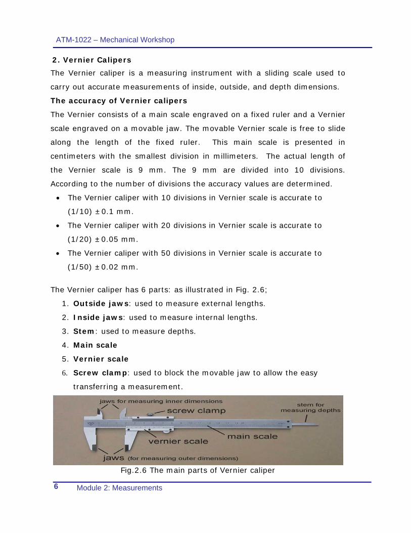
The Vernier caliper has 6 parts: as illustrated in Fig. 2.6;
1. Outside jaws: used to measure external lengths.
2. Inside jaws: used to measure internal lengths.
3. Stem: used to measure depths.
4. Main scale
5. Vernier scale
6. Screw clamp: used to block the movable jaw to allow the easy
transferring a measurement.
Fig.2.6 The main parts of Vernier caliper

ATM-1022 – Mechanical Workshop
Module 2: Measurements 7
Types of Vernier calipers:
A - Standard Vernier caliper. See Fig.2.7.a.
Fig.2.7.a
B - Dial Vernier caliper. See Fig.2.7.b.
Fig.2.7.b
C - Digital Vernier caliper which is easier to read than the other two types. See Fig.2.7.c. Fig.2.7.c
Using Vernier Calipers
Vernier calipers can be used to measure:
A- the outside diameter or width of an object. See Fig. 2.8.a.
Fig. 2.8.a
B- the inside diameter or width of an object. See Fig. 2.8.b.
Fig. 2.8.b
C- the depth of an object. See Fig. 2.8.c.
Fig. 2.8.
ATM-1022 – Mechanical Workshop
Module 2: Measurements 8
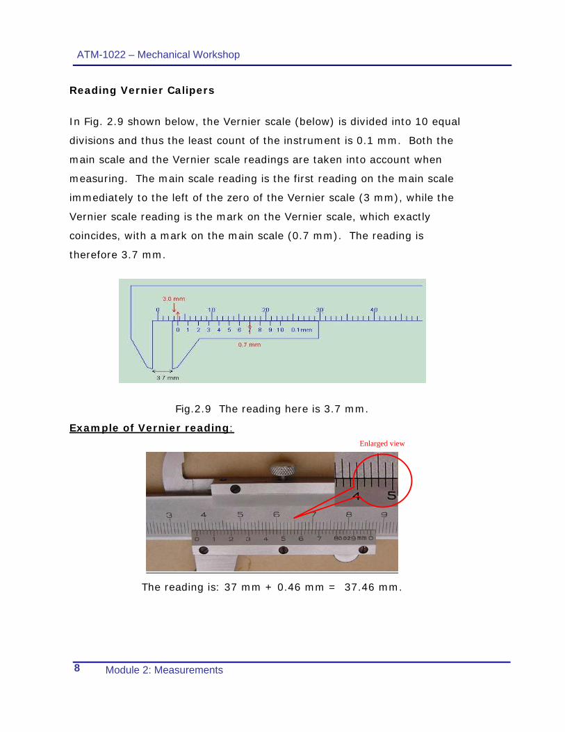
Reading Vernier Calipers
In Fig. 2.9 shown below, the Vernier scale (below) is divided into 10 equal
divisions and thus the least count of the instrument is 0.1 mm. Both the
main scale and the Vernier scale readings are taken into account when
measuring. The main scale reading is the first reading on the main scale
immediately to the left of the zero of the Vernier scale (3 mm), while the
Vernier scale reading is the mark on the Vernier scale, which exactly
coincides, with a mark on the main scale (0.7 mm). The reading is
therefore 3.7 mm.
Fig.2.9 The reading here is 3.7 mm.
Example of Vernier reading:
The reading is: 37 mm + 0.46 mm = 37.46 mm.
Enlarged view

ATM-1022 – Mechanical Workshop
Module 2: Measurements 9
Practical task 2:
You will be given a drill chuck as the
one shown in Fig. 2.10. Use the Vernier
caliper to measure the indicated
dimensions 1 to 7 and record your
readings in the table below.
NOTE: Use a Vernier caliper with 0.02 mm accuracy.
7
2
3
4
5
6
1
Fig. 2.10 a drill chuck

ATM-1022 – Mechanical Workshop
Module 2: Measurements 10
No. Dimension
in (mm) Comment
1
2
3
4
5
6
7
3. Micrometers
The micrometer screw gauge is used to measure even smaller dimensions
than the Vernier calipers. The micrometer screw gauge also uses an
auxiliary scale (measuring hundredths of a millimeter) which is marked on a
rotary thimble. It is a screw with an accurately constant pitch. The
micrometers in our laboratory have a pitch of 0.50 mm (two full turns are
required to close the jaws by 1.00 mm). The rotating thimble is subdivided
into 50 equal divisions. The thimble must be rotated through two revolutions
to open the jaws by 1 mm.
Fig.2.11: The micrometer

ATM-1022 – Mechanical Workshop
Module 2: Measurements 11
Reading the micrometer:
Fig 2.12 Reading the micrometer
Examples of micrometer reading:
The reading in Fig.2.12.a is 7.72 mm.
Fig.2.13.a
The reading in Fig.2.13.a is 7.38 mm.
Fig.2.13.b

ATM-1022 – Mechanical Workshop
Module 2: Measurements 12
Practical task 3:
similar workpiece You will be given a
to the one shown in Fig.2.14. Use
the micrometer to measure the
dimensions shown in Fig. 2.15.
Record your measurements in the
table below.
NOTE: The accuracy of the micrometer is 0.01 mm
Fig.2.14 a copper work piece
Table of measurements
Dimension R1 R2 A B
Dimension in (mm)
ATM-1022 – Mechanical Workshop
Module 2: Measurements 13
Student’s notes
..................................................................................................
..................................................................................................
..................................................................................................
..................................................................................................
..................................................................................................
..................................................................................................
..................................................................................................
..................................................................................................
..................................................................................................
..................................................................................................
..................................................................................................
..................................................................................................
..................................................................................................
..................................................................................................
..................................................................................................
..................................................................................................
..................................................................................................
..................................................................................................
..................................................................................................
..................................................................................................
..................................................................................................
..................................................................................................
..................................................................................................
..................................................................................................
..................................................................................................
..................................................................................................
..................................................................................................

ATM-1022 – Mechanical Workshop
Module 2: Measurements 14
heet No. (1)Work S
The reading is ……………. mm.
The reading is ……………. mm.
.
The reading is ……………. mm.
Enlarged view
Enlarged view
Enlarged view

ATM-1022 – Mechanical Workshop
Module 2: Measurements 15
The reading is ……………. mm.
The reading is ……………. mm.
The reading is ……………. mm.
Enlarged view
Enlarged view
Enlarged view

ATM-1022 – Mechanical Workshop
Module 2: Measurements 16
The reading is ……………. mm.
The reading is ……………. mm.
The reading is ……………. mm.