atmel at09423: sam-ba overview and customization...
TRANSCRIPT

APPLICATION NOTE
AT09423: SAM-BA Overview and Customization Process
ATSAMA5D3x
Introduction
To help customers to benefit of the Atmel® SAM-BA® (SAM Boot Assistant) In-
System Programmer functionalities, this application note provides a full detailed
overview to understand how to customize SAM-BA by creating new custom
boards based on the Atmel evaluation kits.
The aim of the customization is to reuse the existing architecture proposed in
SAM-BA.
The customization guide proposed is based on the SAMA5D3-EK board.
Moreover, this customization process can be reproduced on any Atmel SAM
device based board to get a real custom/user board fully implemented and
accessible from the SAM-BA Graphical User Interface.
Prerequisites
Hardware:
– Atmel SAMA5D3x-EK
– Any SAMA5D3x custom board
Software:
– Atmel SAM-BA 2.12 or higher
– Atmel SAM-BA 2.12 patch 6 or higher
– Sourcery™ CodeBench Lite 2013.05-23 for ARM® EABI
– GNU Make 3.81
– GNU Core utils 5.3
– Notepad ++ (text editor)
Atmel-42438A-SAM-BA-Overview-and-Customization-Process_ApplicationNote_AT09423_062015
AT09423: SAM-BA Overview and Customization Process [APPLICATION NOTE] Atmel-42438A-SAM-BA-Overview-and-Customization-Process_ApplicationNote_AT09423_062015 2
2
Contents
1 SAM-BA Overview ....................................................................................................... 4
1.1 Introduction ........................................................................................................................................... 4
1.1.1 Architecture .............................................................................................................................. 4
1.1.2 How to get SAM-BA Installation File ......................................................................................... 5
1.2 SAM-BA Directory Organization on Windows ....................................................................................... 5
1.2.1 Applets...................................................................................................................................... 6
1.2.2 doc ............................................................................................................................................ 7
1.2.3 drv (Driver) ................................................................................................................................ 7
1.2.4 Example.................................................................................................................................... 7
1.2.5 TCL_lib ..................................................................................................................................... 7
1.3 Graphical User Interface (SAM-BA GUI) ............................................................................................... 8
1.3.1 SAM-BA GUI Overview............................................................................................................. 9
2 Customization Process Overview ............................................................................ 12
2.1 Customization Level Definition ............................................................................................................ 12
2.2 First Level of Customization: The Applet Configuration TCL Files ...................................................... 12
2.3 Second Level of Customization: The Applets Source Code Customization ........................................ 13
2.4 Third Level of Customization: The Applets Source Code Library Customization ................................ 13
2.5 Last level of Customization: Applet Compilation ................................................................................. 14
2.6 Understand Interactions Between tcl/tk Scripts and Applets ............................................................... 14
2.6.1 Customized_board_example.tcl Description ........................................................................... 15
2.6.2 LowLevel.tcl Description ......................................................................................................... 19
3 Software Prerequisites .............................................................................................. 21
3.1 Sourcery CodeBench Lite 2013.05-23 for ARM EABI ......................................................................... 21
3.1.1 Introduction ............................................................................................................................. 21
3.1.2 Installation .............................................................................................................................. 21
3.2 GNU Make 3.81 .................................................................................................................................. 23
3.2.1 Introduction ............................................................................................................................. 23
3.2.2 Installation .............................................................................................................................. 23
3.3 GNU Core Utils 5.3.............................................................................................................................. 25
3.3.1 Introduction ............................................................................................................................. 25
3.3.2 Installation .............................................................................................................................. 25
4 Customization Step 1: Duplicate an Existing Solution as a Base for the
Customization ............................................................................................................ 26
4.1 Duplicate the TCL Folder Organization from an Existing One ............................................................. 26
4.2 Duplicate the Applet Folder Organization from an Existing One ......................................................... 27
5 Customization Step 2: Add a New Custom Board to the Existing TCL Database . 28
5.1 Add a New Board Entry ....................................................................................................................... 28 5.1.1 Modify the “boards.tcl” File ..................................................................................................... 28
6 Customization Step 3: Customize the SAM-BA Graphical User Interface ............. 30
6.1 Add a New Crystal Value in SAM-BA GUI’s ........................................................................................ 30
6.2 Add a New Memory Tab in the SAM-BA GUI Main Window ............................................................... 31
7 Customization Step 5: Modify SAM-BA Applets to fit with a Custom Hardware ... 34
7.1 Customize Low-Level Initialization Applet ........................................................................................... 34
7.1.1 Simple Example ...................................................................................................................... 34

AT09423: SAM-BA Overview and Customization Process [APPLICATION NOTE] Atmel-42438A-SAM-BA-Overview-and-Customization-Process_ApplicationNote_AT09423_062015
3
3
7.1.2 Adapt Existing Applets to the New Hardware ......................................................................... 36
7.2 Low Level Customization to Implement the Oscillator Bypass Mode .................................................. 38
7.2.1 Bypass Mode Overview .......................................................................................................... 38
7.2.2 Summary of the Different Steps to Perform ............................................................................ 40
7.2.3 Step 1: Understanding the Initial Clock Setting During the Boot ROM ................................... 40
7.2.4 Step 2: Understanding the Clock Switching Mechanism ........................................................ 41
7.2.5 Step 3: Defining the Bypass Mode Program Flow .................................................................. 42
7.2.6 Step 4: Bypass Mode Code Implementation ........................................................................... 43
7.3 Customize an External Memory Applet ............................................................................................... 46
7.3.1 External Memory Customization Process Overview ............................................................... 46
7.3.2 Customization Files Overview ................................................................................................ 46
7.3.3 SDR/DDR Customization Example ......................................................................................... 47
8 Compile the SAM-BA Applets and Test Your Modifications ................................... 62
9 References ................................................................................................................. 67
Appendix A Full Implementation of the Bypass Mode ............................................... 68
Appendix B Revision History ....................................................................................... 71

AT09423: SAM-BA Overview and Customization Process [APPLICATION NOTE] Atmel-42438A-SAM-BA-Overview-and-Customization-Process_ApplicationNote_AT09423_062015 4
4
1 SAM-BA Overview
1.1 Introduction
Atmel SAM Boot Assistance (SAM-BA) software provides an open set of tools for programming Atmel AT91SAM
ARM Thumb-based microcontrollers. They are based on a common dynamic linked library (DLL), the
AT91Boot_DLL. It is used by SAM-BA, and all ISP tools.
Customers can use SAM-BA as a tool to program their own board, designed by themselves. But, SAM-BA default
settings are based on Atmel ARM-based evaluation kits and customers might have different crystals and
memories on their own design. In that case SAM-BA needs to be customized.
Before starting the different hands-on assignments let’s clarify start by an overview of SAM-BA.
1.1.1 Architecture
The SAM-BA is composed of two parts; the host and the target device board, as shown in the figure below:
The host part runs on computer. It sends programming files and programming instructions over a download
cable to the target.
The target part is a hardware design, running in the ARM Thumb-based devices. It accepts the programming
data content and required information about the target external memory device which was sent by the host,
and follows the instructions to write/read data to/from the external memory device.
SAM-BA key features:
– Perform in-system programming through JTAG, RS232, or USB interfaces
– Provides both AT91SAM embedded flash programing and external flash programing solutions
– May be used via a Graphical User Interface (GUI) or started in batch mode from a DOS window
– Runs under Windows® 2000, XP, and 7
– Memory and peripheral display content
– User scripts executable from SAM-BA Graphical User Interface or a shell
To learn more about SAM-BA, refer to the AT91 ISP/SAM-BA user guide document available at the following
link: http://www.atmel.com/images/6421b.pdf. Or simply use the SAM-BA user guide document located in
C:\Program Files (x86)\Atmel\sam-ba_X.xx\doc.

AT09423: SAM-BA Overview and Customization Process [APPLICATION NOTE] Atmel-42438A-SAM-BA-Overview-and-Customization-Process_ApplicationNote_AT09423_062015
5
5
1.1.2 How to get SAM-BA Installation File
SAM-BA is available for free directly from this Atmel web page:
http://www.atmel.com/tools/atmelsam-bain-systemprogrammer.aspx
Several components are available:
SAM-BA for Windows (XP, Vista, and 7 editions)
– Install file for the SAM-BA package. SAM-BA User's Guide is included in the package.
SAM-BA 2.12 for Linux®
– SAM-BA Package for Linux
atm6124 USB CDC signed driver for Windows XP, Windows Vista®, Win7, and Win8
– Signed version of atm6124 USB CDC driver
SAM-BA Patch
– This file provides the new features and bugs corrected of the current release of SAM-BA
1.2 SAM-BA Directory Organization on Windows
Once installed on a Windows computer, the runtime directory for SAM-BA is C:\Program Files (x86)\Atmel\sam-
ba_X.xx. In this folder, you will find the sam-ba.exe file and all the files required by SAM-BA when it is running:

AT09423: SAM-BA Overview and Customization Process [APPLICATION NOTE] Atmel-42438A-SAM-BA-Overview-and-Customization-Process_ApplicationNote_AT09423_062015 6
6
The SAMB-BA directory is organized as:
1.2.1 Applets
The base directory of sources is: C:\Program Files (x86)\Atmel\sam-ba_X.xx\applets. This folder is not used
when SAM-BA is running. It just contains the applet sources and instructions on how to build them.
An applet is a small program which is used by SAM-BA in order to be able to program non-volatile memories,
low-level initialization, or other peripherals. For each Atmel AT91SAM device, there is one dedicated applet to
each external memory device the chip can deal with. Each applet contains the programming algorithm for its
dedicated memory.
For instance, with the AT91SAMA5D3x-ek, SAM-BA has to be able to program SDRAM, NAND flash, Data
flash, Serial flash, and NOR flash, which are located in
C:\Program Files (x86)\Atmel\sam-ba_2.12\applets\sama5d3x\sam-ba_applets.
SAM-BA
USB
SAMA5D3x-EK
Applet running
out of internal
RAM
Internal RAM
LowLevelInit
applet
USB
COM
JTAG
AT09423: SAM-BA Overview and Customization Process [APPLICATION NOTE] Atmel-42438A-SAM-BA-Overview-and-Customization-Process_ApplicationNote_AT09423_062015
7
7
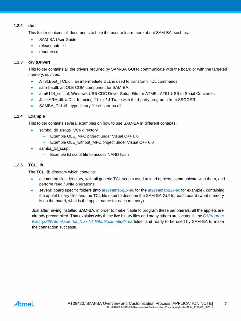
1.2.2 doc
This folder contains all documents to help the user to learn more about SAM-BA, such as:
SAM-BA User Guide
releasenote.txt
readme.txt
1.2.3 drv (Driver)
This folder contains all the drivers required by SAM-BA GUI to communicate with the board or with the targeted
memory, such as:
AT91Boot_TCL.dll: an intermediate DLL is used to transform TCL commands.
sam-ba.dll: an OLE COM component for SAM-BA.
atm6124_cdc.inf: Windows USB CDC Driver Setup File for ATMEL AT91 USB to Serial Converter.
JLinkARM.dll: a DLL for using J-Link / J-Trace with third-party programs from SEGGER.
SAMBA_DLL.tlb: type library file of sam-ba.dll.
1.2.4 Example
This folder contains several examples on how to use SAM-BA in different contexts:
samba_dll_usage_VC6 directory
– Example OLE_MFC project under Visual C++ 6.0
– Example OLE_without_MFC project under Visual C++ 6.0
samba_tcl_script
– Example tcl script file to access NAND flash
1.2.5 TCL_lib
The TCL_lib directory which contains:
a common files directory, with all generic TCL scripts used to load applets, communicate with them, and
perform read / write operations,
several board specific folders (into at91sama5d3x-ek for the at91sama5d3x-ek for example), containing
the applet binary files and the TCL file used to describe the SAM-BA GUI for each board (what memory
is on the board, what is the applet name for each memory).
Just after having installed SAM-BA, in order to make it able to program these peripherals, all the applets are
already precompiled. That explains why these five binary files and many others are located in the C:\Program
Files (x86)\Atmel\sam-ba_X.xx\tcl_lib\at91sama5d3x-ek folder and ready to be used by SAM-BA to make
the connection successful.

AT09423: SAM-BA Overview and Customization Process [APPLICATION NOTE] Atmel-42438A-SAM-BA-Overview-and-Customization-Process_ApplicationNote_AT09423_062015 8
8
1.3 Graphical User Interface (SAM-BA GUI)
Once installed on a Windows computer, SAM-BA is opened by double-clicking on the SAM-BA icon:
The connection window should appear:
If the settings are correct, the SAM-BA GUI window is opened a few seconds after having clicked on “connect”:
Before starting the description of the different fields of the main SAM-BA GUI window, let’s spend some lines to
clarify what has been executed by SAM-BA just before the main window is displayed.
To make the connection between the board and the PC available, several applet executions have been
performed, such as:
Board low-level initialization
Clock settings (PLL, oscillators, crystals, etc.)
Communication (USB, RS232)
eMPU case: dedicated applet to initialize the DDR memories.
Once the low-level initialization is done and the connection is well detected, the communication can start between
the PC and the board. Then the main SAM-BA GUI main window is displayed.

AT09423: SAM-BA Overview and Customization Process [APPLICATION NOTE] Atmel-42438A-SAM-BA-Overview-and-Customization-Process_ApplicationNote_AT09423_062015
9
9
1.3.1 SAM-BA GUI Overview
SAM-BA GUI main window provides several different fields as described in the figure below:
The user can find:
The memory display area: Memory dump.
Memory Download area: Applet Graphical User Interface composed of dedicated memory window tabs
such as:
– EEPROM tabs
– DataFlash tabs
– Serial Flash
– NAND Flash
– Etc.
TCL Shell area: TCL script execution trace.
– With some information about the ongoing connection
The base of the main window stays the Applet Graphical User Interface where the user spends most of time to
program the targeted device memory.
For instance, the NAND FLASH window tabs Memory Download area window tabs, provides a simple way to
upload and download data into internal and external memories. For each memory, files can be sent and received,
and the target’s memory content can be compared with a file on our computer:
Only binary file format is supported by SAM-BA GUI.

AT09423: SAM-BA Overview and Customization Process [APPLICATION NOTE] Atmel-42438A-SAM-BA-Overview-and-Customization-Process_ApplicationNote_AT09423_062015 1
0
10
This area also gives an access to some specific scripts for the different memories available on the board through
a drop-down menu:
During a script execution, the TCL Shell window is used to display the different steps of the applet execution:
At this time, the target handles the programming algorithm by loading applets into the on board XIP memory.
The target switches between two modes:
SAM-BA Monitor Mode: is the command interpreter that runs in the ROM memory when the chip is
connected with USB or COM port to the computer. It allows the computer to send or receive data to/from
the target. All transfers between host and device are done when the device is in SAM-BA monitor mode.
The SAM-BA monitor mnemonics commands are given in the table below:
Command Action Argument(s) Example
N Set Normal Mode No argument N#
T Set Terminal Mode No argument T#
O Write a byte Address, Value# O200001,CA#
o Read a byte Address,# o200001,#
H Write a half word Address, Value# H200002,CAFE#
h Read a half word Address,# h200002,#
W Write a word Address, Value# W200000,CAFEDECA#
w Read a word Address,# w200000,#
S Send a file Address,# S200000,#
R Receive a file Address, NbOfBytes# R200000, 1234#
G Go Address# G200200#
V Display version No argument V#
SAM-BA commands are indeed very basic. They are sent to the applet by using TCL commands as
TCL_WriteData (applet, appletAddr), TCL_WriteInt (applet, appletAddr), TCL_ ReadInt (applet, ap-
pletAddr) from the PC, etc.

AT09423: SAM-BA Overview and Customization Process [APPLICATION NOTE] Atmel-42438A-SAM-BA-Overview-and-Customization-Process_ApplicationNote_AT09423_062015
11
11
Applet Mode: in this mode, the device performs programming operations and is not able to communicate
with the host. As reminder, an applet is a small piece of software running on the target. It is loaded in the
device memory while the device is in SAM-BA monitor mode using TCL_Write command.
The device switches from SAM-BA monitor mode to Applet mode using the TCL_Go command. The device
executes the applet code. At the end of the current operation, the device switches back to SAM-BA monitor mode
as described below:
To learn more on the SAM-BA monitor, refer to the SAMA5D3 product family datasheet found here:
http://www.atmel.com/products/microcontrollers/arm/sama5.aspx?tab=documents.
An applet can execute different programming or initialization commands. Before switching to applet mode, the
host prepares command and arguments data required by the applet in a mailbox mapped in the device
memory.
During its execution, the applet decodes the commands and arguments prepared by the host and execute the
corresponding function. The applet returns state, status and result values in the mailbox area. Usually, applets
include INIT, buffer read, buffer write functions. To program large files, the whole programming operation is
split by the host into payloads. Each payload is sent to a device memory buffer using SAM-BA monitor
command TCL_Write. The host prepares the mailbox with the Buffer write command value, the buffer address
and the buffer size. The host then forces the device in Applet mode using a TCL_Go command. The host polls
the end of payload programming by trying to read the state value in the mailbox. The device will answer to the
host as soon as it returns to SAM-BA monitor mode. In case of USB connection, when the host polls while the
device is in Applet mode, the device NACK IN packets sent by the host.
AT09423: SAM-BA Overview and Customization Process [APPLICATION NOTE] Atmel-42438A-SAM-BA-Overview-and-Customization-Process_ApplicationNote_AT09423_062015 1
2
12
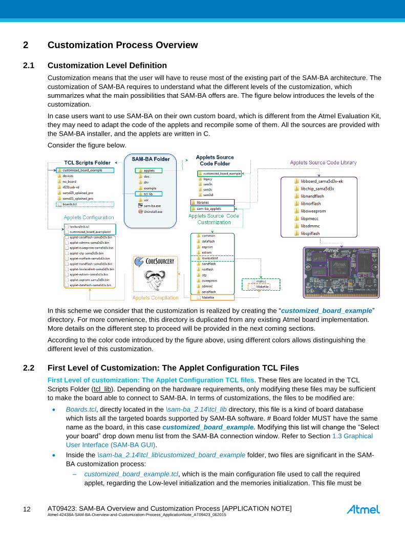
2 Customization Process Overview
2.1 Customization Level Definition
Customization means that the user will have to reuse most of the existing part of the SAM-BA architecture. The
customization of SAM-BA requires to understand what the different levels of the customization, which
summarizes what the main possibilities that SAM-BA offers are. The figure below introduces the levels of the
customization.
In case users want to use SAM-BA on their own custom board, which is different from the Atmel Evaluation Kit,
they may need to adapt the code of the applets and recompile some of them. All the sources are provided with
the SAM-BA installer, and the applets are written in C.
Consider the figure below.
In this scheme we consider that the customization is realized by creating the “customized_board_example”
directory. For more convenience, this directory is duplicated from any existing Atmel board implementation.
More details on the different step to proceed will be provided in the next coming sections.
According to the color code introduced by the figure above, using different colors allows distinguishing the
different level of this customization.
2.2 First Level of Customization: The Applet Configuration TCL Files
First Level of customization: The Applet Configuration TCL files. These files are located in the TCL
Scripts Folder (tcl_lib). Depending on the hardware requirements, only modifying these files may be sufficient
to make the board able to connect to SAM-BA. In terms of customizations, the files to be modified are:
Boards.tcl, directly located in the \sam-ba_2.14\tcl_lib directory, this file is a kind of board database
which lists all the targeted boards supported by SAM-BA software. # Board folder MUST have the same
name as the board, in this case customized_board_example. Modifying this list will change the “Select
your board” drop down menu list from the SAM-BA connection window. Refer to Section 1.3 Graphical
User Interface (SAM-BA GUI).
Inside the \sam-ba_2.14\tcl_lib\customized_board_example folder, two files are significant in the SAM-
BA customization process:
– customized_board_example.tcl, which is the main configuration file used to call the required
applet, regarding the Low-level initialization and the memories initialization. This file must be

AT09423: SAM-BA Overview and Customization Process [APPLICATION NOTE] Atmel-42438A-SAM-BA-Overview-and-Customization-Process_ApplicationNote_AT09423_062015
13
13
modified when the user wants to customized SAM-BA according to the application hardware
requirements.
– lowlevelinit.tcl, this file is used to call the low-level initialization applet. From this file the user is
able to select what kind of clock configuration he has to use regarding the application.
2.3 Second Level of Customization: The Applets Source Code Customization
Second Level of Customization: The Applets Source Code Customization. In this level, the user
understood that modifying the Applet Configuration TCL files, is not sufficient regarding the hardware
requirements of his application. In this case, the user has to dig into the applet architecture to figure out how it
is possible to reuse the main low-level functions implemented into the provided libraries. Once the
modifications are done the applets needs to be recompiled. In terms of customization the applet source
code are located inside the \sam-ba_2.14\applets\customized_board_example directory, duplicated from any
other existing applet directory which contains two sub-directories:
Libraries: This directory provides all the low-level drivers developed by Atmel Engineers for the targeted
device and for the board requirements. The next level of customization will provide more details on this
section.
sam-ba_applets: Contains several sub-folders and the makefile used to recompile the applets.
Depending on the hardware memory set, one directory per memory is provided. If the user has
duplicated the existing sama5d3x applet directory to generate his own customized_board_example the
directory set should look-like this:
– Common\
– Dataflash\
– Eeprom\
– Extram\
– Lowlevelinit\
– Nandflash\
– Norflash\
– Otp\
– Oweeprom\
– Sdmmc\
– Serialflash\
– Makefile
Most of these folders are related to a hardware memory, except the lowlevelinit which is related to the
main clock configurations. Depending on the hardware configuration of the custom board, the user will
have to modify the main.c file provided inside each directory.
2.4 Third Level of Customization: The Applets Source Code Library Customization
Third Level of Customization: The Applets Source Code Library Customization. This level of the
customization is the highest one mostly required when the user wants to modify the low level driver of a
memory, a peripheral, or of the clock configuration while the provided low level driver does not fit with the
application requirements. For instance, the user application DDR or the LPDDR memory does not match with
the one initially related to the Atmel evaluation kit, the memory architecture and/or the timings need to be
modified. This directory is a legacy of the Atmel Software package and contains the following architecture:
libboard_sama5d3x-ek\
libchip_sama5d3x\
libnandflash\

AT09423: SAM-BA Overview and Customization Process [APPLICATION NOTE] Atmel-42438A-SAM-BA-Overview-and-Customization-Process_ApplicationNote_AT09423_062015 1
4
14
libnorflash\
liboweeprom\
libpmecc\
libsdmmc\
libspiflash\
In this application note we are going to address different user cases but we consider a custom board initially
based on the SAMA5D3x-EK, which is already supported in SAM-BA. So we will reuse most part of the existing
applets for this evaluation kit.
2.5 Last Level of Customization: Applet Compilation
Last level of Customization: Applet compilation: Once an applet is modified either from the Second Level
or the Third level of the customization, it needs to be recompiled. Using the makefile provided from the sam-
ba_2.14\applets\customized_board_example\ sam-ba_applets\ directory.
The next section will introduce the tools required to compile an Applet under a windows computer.
Once compiled each binary is then automatically copied into the directory: \sam-
ba_2.14\tcl_lib\customized_board_example.
The last chapter of this application note explain how to recompile an applet.
2.6 Understand Interactions Between tcl/tk Scripts and Applets
In this section the aim is to understand the .tcl files used to communicate with an applet:
After having a look at the \sam-ba_2.14\tcl_lib\customized_board_example the following architecture can be
observable:
Two different types of files are in this folder:
Binaries: By default SAM-BA provides all the binaries initially required to connect to an Atmel board. This
folder contains all the initial binaries. But once compiled each binary is then automatically copied into the
directory, erasing the previous ones. The proposed method of duplicating makes sense if the user does
not want to break the initial component of SAM-BA.

AT09423: SAM-BA Overview and Customization Process [APPLICATION NOTE] Atmel-42438A-SAM-BA-Overview-and-Customization-Process_ApplicationNote_AT09423_062015
15
15
TCL files:
– customized_board_example.tcl, which is the main configuration file used to call the required
applet, regarding the Low-level initialization and the memories initialization. This file must be
modified when the user wants to customize SAM-BA GUI according to the application hardware
requirements, by adding additional window tab for example.
– lowlevelinit.tcl, this file is used to call the low-level initialization applet. From this file the user is
able to select what kind of clock configuration he has to use regarding the application.
2.6.1 Customized_board_example.tcl Description
This file is composed of several parts used
to configure the hardware the applets has to address.
to add the memory options to the Graphical User Interface.
CHIP Name: Specifies the chip ID and configure some global parameters to make the applet able to
check if the ongoing function is compliant with the chip.
BOARD Specific Parameters: This part is used to provide some hardware arguments to the applet such
as:
– extRamVdd: Specifies the Power supply Voltage value for the external memory, to the applet.
– extRamType: Specifies the external memory type to the applet.
– extRamDataBusWidth: Specifies the external memory data bus width to the applet.
– extDDRamModel: Specifies the model of DDR used (this option is mainly used for common
memories used across the Atmel Evaluation Kits). ################################################################################
## BOARD SPECIFIC PARAMETERS
################################################################################
namespace eval BOARD
variable sramSize 0x20000
variable maxBootSize 65328
# Default setting for DDRAM
# Vdd Memory 1.8V = 0 / Vdd Memory 3.3V = 1
variable extRamVdd 0
# External SDRAM = 0 / External DDR2 = 1 / LPDDR = 2
variable extRamType 1
#!!!!!!!!!!!!!!!!!!!!!!!!!!!!!!!!!!!!!!!!!!!!!!!!!!!!!!!!!!!!
#For LPDDR change me here
#variable extRamType 2
#!!!!!!!!!!!!!!!!!!!!!!!!!!!!!!!!!!!!!!!!!!!!!!!!!!!!!!!!!!!!
# Set bus width (16 or 32)
variable extRamDataBusWidth 16
# DDRAM Model (0: MT47H64M16HR, 1: MT47H128M16RT
variable extDDRamModel 1
# Note: DEVICE/ADDRESSES (A2, A1, A0): The A2, A1 or A0 pins are device address inputs
# that are hardwired or left not connected for hardware compatibility with other AT24CXX
devices.
# Modify 'eepromDeviceAddress' to meet the hardware connection.
variable eepromDeviceAddress 0x51
set target(board) at91sama5d3x-ek
# Source procedures for compatibility with older SAM-BA versions
if [ catch source "$libPath(extLib)/common/functions.tcl" errMsg]
if $commandLineMode == 0
tk_messageBox -title "File not found" -message "Function file not found:\n$errMsg" -
type ok -icon error
else
puts "-E- Function file not found:\n$errMsg"
puts "-E- Connection abort"
AT09423: SAM-BA Overview and Customization Process [APPLICATION NOTE] Atmel-42438A-SAM-BA-Overview-and-Customization-Process_ApplicationNote_AT09423_062015 1
6
16
exit
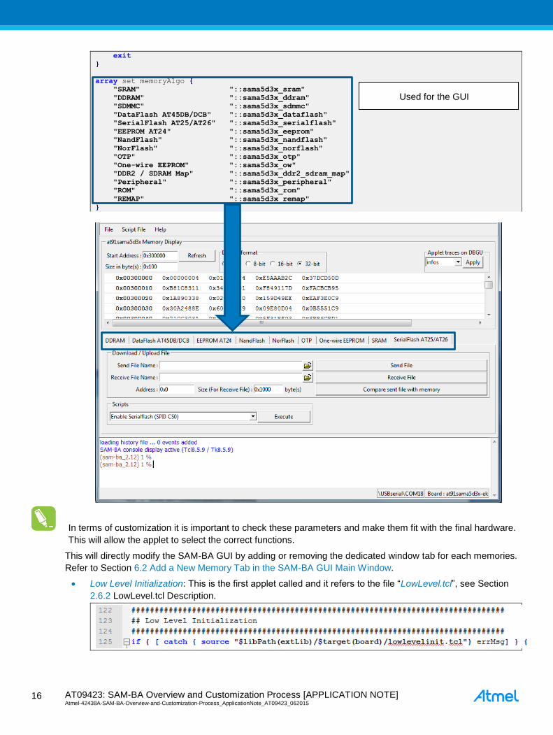
array set memoryAlgo
"SRAM" "::sama5d3x_sram"
"DDRAM" "::sama5d3x_ddram"
"SDMMC" "::sama5d3x_sdmmc"
"DataFlash AT45DB/DCB" "::sama5d3x_dataflash"
"SerialFlash AT25/AT26" "::sama5d3x_serialflash"
"EEPROM AT24" "::sama5d3x_eeprom"
"NandFlash" "::sama5d3x_nandflash"
"NorFlash" "::sama5d3x_norflash"
"OTP" "::sama5d3x_otp"
"One-wire EEPROM" "::sama5d3x_ow"
"DDR2 / SDRAM Map" "::sama5d3x_ddr2_sdram_map"
"Peripheral" "::sama5d3x_peripheral"
"ROM" "::sama5d3x_rom"
"REMAP" "::sama5d3x_remap"
In terms of customization it is important to check these parameters and make them fit with the final hardware.
This will allow the applet to select the correct functions.
This will directly modify the SAM-BA GUI by adding or removing the dedicated window tab for each memories.
Refer to Section 6.2 Add a New Memory Tab in the SAM-BA GUI Main Window.
Low Level Initialization: This is the first applet called and it refers to the file “LowLevel.tcl”, see Section
2.6.2 LowLevel.tcl Description.
Used for the GUI

AT09423: SAM-BA Overview and Customization Process [APPLICATION NOTE] Atmel-42438A-SAM-BA-Overview-and-Customization-Process_ApplicationNote_AT09423_062015
17
17
SRAM: Specifies the address of the internal SRAM of the chip, the size and the script used to write or
read the internal SRAM.
###########################################################################
#####
## SRAM
###########################################################################
#####
array set sama5d3x_sram
dftDisplay 1
dftDefault 0
dftAddress 0x00300000
dftSize 0x10000
dftSend "RAM::sendFile"
dftReceive "RAM::receiveFile"
dftScripts ""
The functions “RAM::sendFile & RAM::receiveFile” are implemented in the directory sam-
ba_2.14\tcl_lib\common\ in the file generic.tcll.
If this file is opened, it can be understood how the function
“send file” is managed using the TCL_Write_Data function which directly comes from the
AT91Boot_TCL.dll file.
“receive file” is managed using the TCL_Read_Data function which directly comes from the
AT91Boot_TCL.dll file.
DDRAM: This part is important to be considered in terms of the customization of SAM-BA. All the board
parameters previously configured from the “BOARD Specific Parameters” will determine the final
arguments sent to the applet mailbox in the low_level_init.tcl file.
################################################################################
## DDRAM
################################################################################
array set sama5d3x_ddram
dftDisplay 0
dftDefault 0
dftAddress 0x20000000
dftSize "$GENERIC::memorySize"
dftSend "RAM::sendFile"
dftReceive "RAM::receiveFile"
dftScripts "::sama5d3x_ddram_scripts"
if $BOARD::extRamType == 1 || $BOARD::extRamType == 2
set sama5d3x_ddram(dftDisplay) 1
set RAM::appletAddr 0x308000
set RAM::appletMailboxAddr 0x308004
set RAM::appletFileName "$libPath(extLib)/$target(board)/applet-extram-
sama5d3x.bin"
puts "-I- External RAM Settings : extRamVdd=$BOARD::extRamVdd, ex-
tRamType=$BOARD::extRamType, extRamDataBusWidth=$BOARD::extRamDataBusWidth, ex-
tDDRamModel=$BOARD::extDDRamModel"
array set sama5d3x_ddram_scripts
"Enable DDR2" "GENERIC::Init $RAM::appletAddr $RAM::appletMailboxAddr
$RAM::appletFileName [list $::target(comType) $::target(traceLevel) $BOARD::ex-
tRamVdd 1 $BOARD::extRamDataBusWidth $BOARD::extDDRamModel]"
"Enable LPDDR2" "GENERIC::Init $RAM::appletAddr $RAM::appletMailboxAddr
$RAM::appletFileName [list $::target(comType) $::target(traceLevel) $BOARD::ex-
tRamVdd 2 $BOARD::extRamDataBusWidth $BOARD::extDDRamModel]"

AT09423: SAM-BA Overview and Customization Process [APPLICATION NOTE] Atmel-42438A-SAM-BA-Overview-and-Customization-Process_ApplicationNote_AT09423_062015 1
8
18
# Initialize SDRAM/DDRAM
if [catch GENERIC::Init $RAM::appletAddr $RAM::appletMailboxAddr $RAM::ap-
pletFileName [list $::target(comType) $::target(traceLevel) $BOARD::extRamVdd
$BOARD::extRamType $BOARD::extRamDataBusWidth $BOARD::extDDRamModel] dummy_err]
set continue no
if $commandLineMode == 0
set continue [tk_messageBox -title "External RAM init" -message "External
RAM initialization failed.\nExternal RAM access is required to run applets.\nCon-
tinue anyway ?" -icon warning -type yesno]
else
puts "-E- Error during external RAM initialization."
puts "-E- External RAM access is required to run applets."
puts "-E- Connection abort"
# Close link
if $continue == no
TCL_Close $target(handle)
exit
else
puts "-I- External RAM initialized"
SERIALFLASH; DATAFLASH; EEPROM; One-Wire EEPROM; NANDFLASH; SDMMC; NORFLASH;
OTP; these parts are all composed of the same fields used to determine the graphical menu in the SAM-
BA GUI for each memory. Example given for the NANDFLASH:

AT09423: SAM-BA Overview and Customization Process [APPLICATION NOTE] Atmel-42438A-SAM-BA-Overview-and-Customization-Process_ApplicationNote_AT09423_062015
19
19
2.6.2 LowLevel.tcl Description
This file is used to call the low-level initialization applet.
In SAM-BA, there is a new feature, Customize lowlevel, which allows users to configure the Master Clock
(MCK) of the target device in an easier way.
In each board specific folder, there is a tcl/tk script named lowlevel.tcl. The <board>.tcl will call a function,
LOWLEVEL::Init, which is defined in lowlevel.tcl.
In lowlevel.tcl, the list mainOsc(crystalList) contains all available crystal frequencies of the device. Users can
add a user-defined frequency to the list.
A dedicated applet, lowlevelinit applet, implements the low level initialization. Like other applets, the address,
the mailbox address, and the applet name of this lowlevel applet are defined.
There are three key parameters transferred to the applet by SAM-BA.
set mainOsc(crystalList) [list \
"12000000" ]
set mainOsc(initOsc) 0
set mainOsc(initXal) 12000000
namespace eval LOWLEVEL
variable appletAddr 0x308000
variable appletMailboxAddr 0x308004
variable appletFileName "$libPath(extLib)/$target(board)/applet-lowlev-
elinit-sama5d3x.bin"
Mode specifies the mode of low level initialization.
If mode is EK_MODE, the applet will call EK_LowLevelInit() to configure the target device just the same
as EK does.
If mode is USER_DEFINED_CRYSTAL, the applet will call user_defined_LowlevelInit() to configure the
target device, which should be implemented by users. A selected frequency will be passed to this
function as a parameter, named crystalFreq.
If mode is BYPASS_MODE, the target device should be configured to be clocked by an external clock.
Function bypass_LowLevelInit() should be implemented by users to complete the configuration. A
specified frequency will be passed to this function as a parameter, named extClk.
CrystalFreq is the selected frequency of the crystal oscillator. The value of the frequency is one of those in the
list mainOsc(crystalList), which is defined in lowlevel.tcl. CrystalFreq is used by user_defined_LowlevelInit()
when mode is USER_DEFINED_CRYSTAL.
Extclk is the specified frequency of the external clock of the target device. The value of the frequency is
specified by users in SAM-BA GUI. Extclk is used by bypass_LowlevelInit() when mode is BYPASS_MODE.
proc LOWLEVEL::Init
global mainOsc
global commandLineMode
global target
switch $mainOsc(mode)
bypassMode
set mode 2

AT09423: SAM-BA Overview and Customization Process [APPLICATION NOTE] Atmel-42438A-SAM-BA-Overview-and-Customization-Process_ApplicationNote_AT09423_062015 2
0
20
boardCrystalMode
set mode 1
default
set mode 0
If the user’s board is mounted with a crystal of a frequency different from that on the EK board or the target
device is clocked by an external clock, the function user_defined_LowlevelInit() or bypass_LowLevelInit()
should be implemented in advance and the low-level applet needs to be re-compiled and replace the one in the
board specific folder. For information on how to implement the low level initialization, refer to
EK_LowLevelInit(), or refer to Section 7.2 Low Level Customization to Implement the Oscillator Bypass Mode.
Once the parameters set, the mailbox is ready to be sent to the applet containing all the parameters:
if [catch GENERIC::Init $LOWLEVEL::appletAddr $LOWLEVEL::appletMailboxAddr
$LOWLEVEL::appletFileName [list $::target(comType) $::target(traceLevel) $mode
$mainOsc(osc) $mainOsc(xal)] dummy_err]
set continue no
if $commandLineMode == 0
set continue [tk_messageBox -title "Low level init" -message "Low
level initialization failed.\nLow level initialization is required to run ap-
plets.\nContinue anyway ?" -icon warning -type yesno]
else
puts "-E- Error during Low level initialization."
puts "-E- Low level initialization is required to run applets."
puts "-E- Connection abort!"
# Close link
if $continue == no
TCL_Close $target(handle)
exit
else
puts "-I- Low level initialized"

AT09423: SAM-BA Overview and Customization Process [APPLICATION NOTE] Atmel-42438A-SAM-BA-Overview-and-Customization-Process_ApplicationNote_AT09423_062015
21
21
3 Software Prerequisites
This chapter describes how to install all the required software tools to compile the new applets, which must be
done before starting a customization case.
3.1 Sourcery CodeBench Lite 2013.05-23 for ARM EABI
3.1.1 Introduction
Sourcery G++ Lite for ARM EABI is intended for developers working on
embedded applications or firmware for boards without an operating system, or
that run an RTOS or boot loader. This Sourcery CodeBench™ configuration is
not intended for Linux or µClinux™ kernel, or application development.
Download link:
http://www.mentor.com/embedded-software/sourcery-tools/sourcery-codebench/editions/lite-edition/
3.1.2 Installation
Execute the arm-2013.05-23-arm-none-eabi.exe file and follow the instructions:
– Choose “Typical” option in step 3
– Choose “Modify PATH for all users” option in step 5

AT09423: SAM-BA Overview and Customization Process [APPLICATION NOTE] Atmel-42438A-SAM-BA-Overview-and-Customization-Process_ApplicationNote_AT09423_062015 2
2
22
– Follow next instructions till the install process starts
– Press “Done” at the end of the install process
Once the installation process is finished, verify whether ARM EABI’s PATH environment variable has
been correctly added in system:
– Open a “Command Prompt” in Windows (Start -> Accessories -> Command Prompt)
– Type “arm-none-eabi-gcc -v” in command line to check the version number
– The following results should be displayed:
If you cannot see this information, the install process did not correctly set the PATH variable during Code CodeBench Lite 2012.05-23 for ARM EABI installation.
In this case, add the PATH variable manually as described:
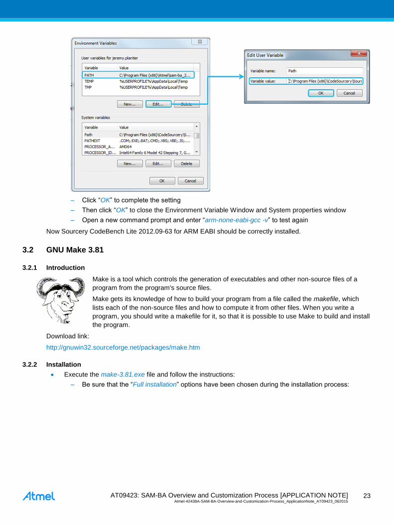
– Right click on (My)”Computer -> Properties -> Advanced Systems Settings->Advanced ->
Environment Variables -> User variables -> PATH”
– Select the “PATH” user variables and click “Edit”
For Windows 32-bit OS users: add “C:\Program
Files\CodeSourcery\Sourcery_CodeBench_Lite_for_ARM_EABI\bin” at the beginning of
Variable value box.
For Windows 64-bit OS users: add “C:\Program Files
(x86)\CodeSourcery\Sourcery_CodeBench_Lite_for_ARM_EABI\bin” at the beginning of
Variable value box.
AT09423: SAM-BA Overview and Customization Process [APPLICATION NOTE] Atmel-42438A-SAM-BA-Overview-and-Customization-Process_ApplicationNote_AT09423_062015
23
23
– Click “OK” to complete the setting
– Then click “OK” to close the Environment Variable Window and System properties window
– Open a new command prompt and enter “arm-none-eabi-gcc -v” to test again
Now Sourcery CodeBench Lite 2012.09-63 for ARM EABI should be correctly installed.
3.2 GNU Make 3.81
3.2.1 Introduction
Make is a tool which controls the generation of executables and other non-source files of a
program from the program's source files.
Make gets its knowledge of how to build your program from a file called the makefile, which
lists each of the non-source files and how to compute it from other files. When you write a
program, you should write a makefile for it, so that it is possible to use Make to build and install
the program.
Download link:
http://gnuwin32.sourceforge.net/packages/make.htm
3.2.2 Installation
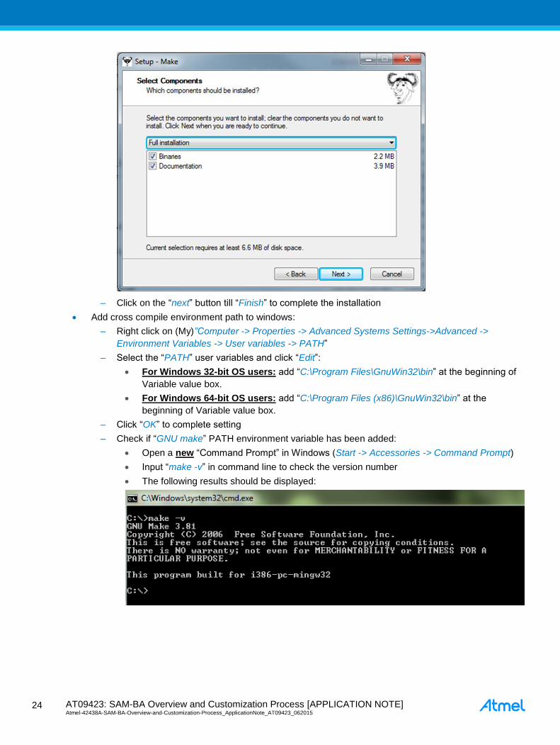
Execute the make-3.81.exe file and follow the instructions:
– Be sure that the “Full installation” options have been chosen during the installation process:
AT09423: SAM-BA Overview and Customization Process [APPLICATION NOTE] Atmel-42438A-SAM-BA-Overview-and-Customization-Process_ApplicationNote_AT09423_062015 2
4
24
– Click on the “next” button till “Finish” to complete the installation
Add cross compile environment path to windows:
– Right click on (My)”Computer -> Properties -> Advanced Systems Settings->Advanced ->
Environment Variables -> User variables -> PATH”
– Select the “PATH” user variables and click “Edit”:
For Windows 32-bit OS users: add “C:\Program Files\GnuWin32\bin” at the beginning of
Variable value box.
For Windows 64-bit OS users: add “C:\Program Files (x86)\GnuWin32\bin” at the
beginning of Variable value box.
– Click “OK” to complete setting
– Check if “GNU make” PATH environment variable has been added:
Open a new “Command Prompt” in Windows (Start -> Accessories -> Command Prompt)
Input “make -v” in command line to check the version number
The following results should be displayed:

AT09423: SAM-BA Overview and Customization Process [APPLICATION NOTE] Atmel-42438A-SAM-BA-Overview-and-Customization-Process_ApplicationNote_AT09423_062015
25
25
3.3 GNU Core Utils 5.3
3.3.1 Introduction
The GNU Core Utilities are the basic file, shell and text manipulation utilities of the GNU operating system.
These are the core utilities which are expected to exist on every operating system. This tool package contains
Linux tools like mkdir, rm, sh, touch, and more. It will be used by Makefile, which is used to compile the SAM-
BA applets.
Download link:
http://gnuwin32.sourceforge.net/packages/coreutils.htm
3.3.2 Installation
Execute the coreutils-5.3.0.exe and follow the instructions:
– Make sure you have selected “Full installation” options during installation
– Click on the “next” button till “Finish” to complete the installation
AT09423: SAM-BA Overview and Customization Process [APPLICATION NOTE] Atmel-42438A-SAM-BA-Overview-and-Customization-Process_ApplicationNote_AT09423_062015 2
6
26
4 Customization Step 1: Duplicate an Existing Solution as a Base for the
Customization
4.1 Duplicate the TCL Folder Organization from an Existing One
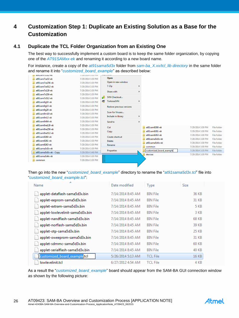
The best way to successfully implement a custom board is to keep the same folder organization, by copying
one of the AT91SAMxx-ek and renaming it according to a new board name.
For instance, create a copy of the at91sama5d3x folder from sam-ba_X.xx/tcl_lib directory in the same folder
and rename it into “customized_board_example” as described below:
Then go into the new “customized_board_example” directory to rename the “at91sama5d3x.tcl” file into
“customized_board_example.tcl”:
As a result the “customized_board_example” board should appear from the SAM-BA GUI connection window
as shown by the following picture:
AT09423: SAM-BA Overview and Customization Process [APPLICATION NOTE] Atmel-42438A-SAM-BA-Overview-and-Customization-Process_ApplicationNote_AT09423_062015
27
27
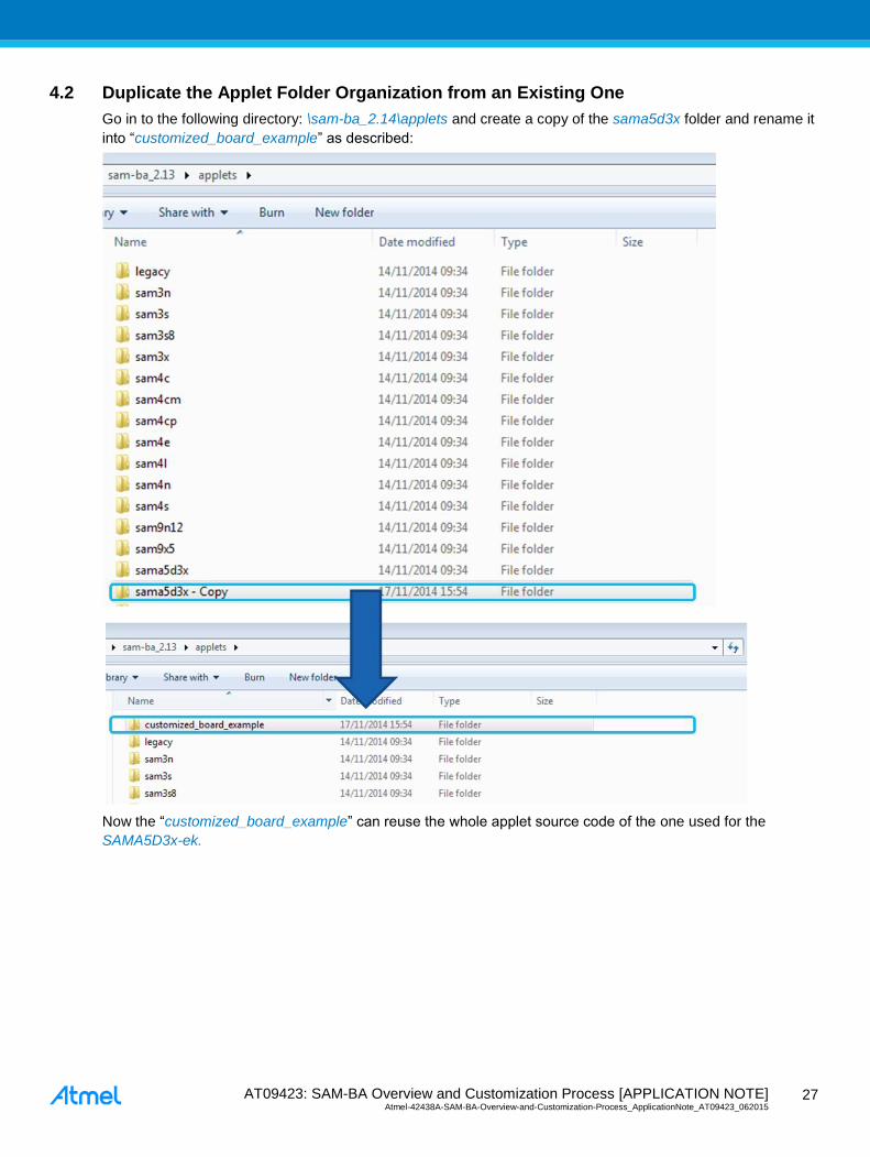
4.2 Duplicate the Applet Folder Organization from an Existing One
Go in to the following directory: \sam-ba_2.14\applets and create a copy of the sama5d3x folder and rename it
into “customized_board_example” as described:
Now the “customized_board_example” can reuse the whole applet source code of the one used for the
SAMA5D3x-ek.

AT09423: SAM-BA Overview and Customization Process [APPLICATION NOTE] Atmel-42438A-SAM-BA-Overview-and-Customization-Process_ApplicationNote_AT09423_062015 2
8
28
5 Customization Step 2: Add a New Custom Board to the Existing TCL
Database
5.1 Add a New Board Entry
To add support for a new board, a new device entry must be added in the devices array at first. Adding a new
board entry allows to add a new board instance in the drop-down menu of the SAM-BA startup screen.
For example, if users have their own boards with SAMA5D3x device; add alias customized_board_example in
the original line for SAMA5D3x device.
5.1.1 Modify the “boards.tcl” File
The “boards.tcl” file is used to make SAM-BA able to load the corresponding applets of the specified board. As
a consequence, a new entry must be added in the board array with an associated description file path. Then a
dedicated directory must be created (see below).
The figure below shows that for each Atmel evaluation kit, a dedicated path is provided to SAM-BA allowing the
dedicated applet to load correctly. The aim in this step is to reproduce this architecture for a custom example.
The file is located in the directory C:\Program Files (x86)\Atmel\sam-ba_X.xx\tcl_lib:
Open the boards.tcl file in a text editor with a syntax recognition (e.g.: Notepad++) and add a new board by
adding a new entry in the “set boards” array ‘from code line #107) and the corresponding directory, as
explained below:
The directory must have the same name as the board. Take care that the text editor used is executed as
administrator, otherwise saving files will fail.
To apply the previous modifications, SAM-BA GUI must be restarted if required.

AT09423: SAM-BA Overview and Customization Process [APPLICATION NOTE] Atmel-42438A-SAM-BA-Overview-and-Customization-Process_ApplicationNote_AT09423_062015
29
29
Once the board is registered in the database, its functionality remains to be implemented through the applet
customization. The previous implementation simply allows SAM-BA to be able to load the applets binaries file
when a dedicated command is sent to SAM-BA GUI.

AT09423: SAM-BA Overview and Customization Process [APPLICATION NOTE] Atmel-42438A-SAM-BA-Overview-and-Customization-Process_ApplicationNote_AT09423_062015 3
0
30
6 Customization Step 3: Customize the SAM-BA Graphical User Interface
In this chapter, how to add / or to modify the SAM-GA GUI features is explained. The following two examples
are targeted to be the most common part the users/customers are supposed to meet.
The first example is about how to customize TCL/TK script to add a new crystal value from the “customize low
level” option of the SAM-BA GUI’s connection window.
The second example is about how to modify or to add a new memory tab to the SAM-BA GUI’s main window.
6.1 Add a New Crystal Value in SAM-BA GUI’s
From SAM-BA 2.11 and 2.12, a new option is available: “Customize low level” which allows users to configure
the Master Clock (MCK) of the target device in an easier way, as for example for the SAMA5D3x-ek below:
In each board specific folder, there is a tcl/tk script named lowlevel.tcl. The <board>.tcl will call a command
through SAM-BA, LOWLEVEL::Init, which is used in lowlevel.tcl.
In this step we will make the assumption that a different onboard crystal is used. As a consequence the main
oscillator low_level_init function has to be modified to fit with the new hardware modifications. Therefore, the
corresponding applet will be modified accordingly and recompiled.
Now, go to the directory C:\Program Files (x86)\Atmel\sam-ba_2.12\tcl_lib\ customized_board_example and
open the lowlevelinit.tcl file in a text editor. In this file the list mainOsc(crystalList) contains all available crystal
frequencies of the device. Users can add a user-defined frequency to the list.
For instance, from the SAMA5D3x product family datasheet available in the Resources\Datasheet folder, in the
Electrical chapter, we can read that the main oscillator operating frequency is in the range 8MHz to 16MHz.

AT09423: SAM-BA Overview and Customization Process [APPLICATION NOTE] Atmel-42438A-SAM-BA-Overview-and-Customization-Process_ApplicationNote_AT09423_062015
31
31
The list mainOsc(crystalList) must be modified in the lowlevel.tcl file located in the C:\Program Files
(x86)\Atmel\sam-ba_2.12\tcl_lib\customized_board_example directory as in this example:
A dedicated applet, lowlevelinit applet, implements the low level initialization. Like other applets, the address,
the mailbox address, and the applet name of this lowlevel applet are defined as described in the lowlevel.tcl:
Now, restart SAM-BA and click on the “customize low level” check box to see the modifications.
6.2 Add a New Memory Tab in the SAM-BA GUI Main Window
To add a new memory window tab in the SAM-BA GUI main window, the file “customized_board_example” has
to be modified.
The customized_board_example.tcl file is located in the directory \sam-
ba_2.14\tcl_lib\customized_board_example, and can be opened the in a text editor.
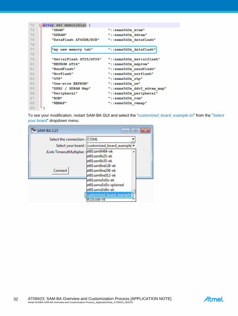
In customized_board_example.tcl, the “set memoryAlgo” array contains all available window tabs
corresponding to each memory on board. Users can add a new one by adding an instance to the “set
memoryAlgo” array as described below.
To add a new tab, modify the “set memoryAlgo” array in the customized_board_example.tcl file located in
\sam-ba_2.14\tcl_lib\ customized_board_example directory as explained below:
AT09423: SAM-BA Overview and Customization Process [APPLICATION NOTE] Atmel-42438A-SAM-BA-Overview-and-Customization-Process_ApplicationNote_AT09423_062015 3
2
32
To see your modification, restart SAM-BA GUI and select the “customized_board_example.tcl” from the ”Select
your board” dropdown menu:

AT09423: SAM-BA Overview and Customization Process [APPLICATION NOTE] Atmel-42438A-SAM-BA-Overview-and-Customization-Process_ApplicationNote_AT09423_062015
33
33
The SAM-BA GUI main window should appear as follow:
As a result, the new memory tab appears.

AT09423: SAM-BA Overview and Customization Process [APPLICATION NOTE] Atmel-42438A-SAM-BA-Overview-and-Customization-Process_ApplicationNote_AT09423_062015 3
4
34
7 Customization Step 5: Modify SAM-BA Applets to fit with a Custom
Hardware
7.1 Customize Low-Level Initialization Applet
7.1.1 Simple Example
In this example, the lowlevelinit.tcl file is opened in a text editor; Go to the directory \sam-ba_2.14\tcl_lib\
customized_board_example and reopen the lowlevelinit.tcl file in a text editor.
In the LOWLEVEL::Init procedure, from the code line #43, Mode specifies the mode of low level initialization.
If mode is EK_MODE, the applet will call EK_LowLevelInit() to configure the target device just the same
as EK does
If mode is USER_DEFINED_CRYSTAL, the applet will call user_defined_LowlevelInit() to configure the
target device, which should be implemented by the users. A selected frequency will be passed on to this
function as a parameter, named crystalFreq.
If mode is BYPASS_MODE, the target device should be configured to be clocked by an external clock.
Function bypass_LowLevelInit() should be implemented by the users to complete the configuration. A
specified frequency will be passed on to this function as a parameter, named extClk.
We can see there that the tcl/tk script call a different function which directly depends on the selected mode
from the SAM-BA GUI first window.
The parameters are sent to the applet by using this command line from the lowlevelinit.tcl tcl/tk script:
The lowlevelinit.tcl tcl/tk script calls another tcl/tk script, GENERIC::Init which is used to extract the parameters
to be sent to the applet.
This script can be found from the .\sam-ba_2.14\tcl_lib\common directory by opening the generic.tcl file.
As a result go to the directory path:
..\sam-ba_2.14\applets\my_training_board\sam-ba_applets\lowlevelinit and open the main.c file in code line
#170 to see the applet implementation, which depends on the selected mode from the lowlevel.tcl script:

AT09423: SAM-BA Overview and Customization Process [APPLICATION NOTE] Atmel-42438A-SAM-BA-Overview-and-Customization-Process_ApplicationNote_AT09423_062015
35
35
The cases “EK_MODE”, “USER_DEFINED_CRYSTAL” & “BYPASS” are well defined at the code line #43-45
and correspond to the different mode from the tcl/tk script.
CrystalFreq is the selected frequency of the crystal oscillator. The value of the frequency is one of those in the
list mainOsc(crystalList), which is defined in lowlevel.tcl. CrystalFreq used by user_defined_LowlevelInit() when
the mode is USER_DEFINED_CRYSTAL.
Extclk is the specified frequency of the external clock of the target device. The value of the frequency is
specified by users in SAM-BA GUI. Extclk is used by bypass_LowlevelInit() when mode is BYPASS_MODE.
If user’s board mounts a crystal of a frequency different from the one available on the EK board, or the target
device is clocked by an external clock, the function user_defined_LowlevelInit() or bypass_LowLevelInit()
should be implemented in advance and the lowlevel applet needs to be recompiled and should replace the one
in the C:\Program Files (x86)\Atmel\sam-ba_2.12\tcl_lib\my_training_board folder.
In our case only the user_defined_LowlevelInit() will be implemented in this hands-on.

AT09423: SAM-BA Overview and Customization Process [APPLICATION NOTE] Atmel-42438A-SAM-BA-Overview-and-Customization-Process_ApplicationNote_AT09423_062015 3
6
36
Before starting to implement the user_defined_LowlevelInit(), go to the EK_LowLevelInit() function (code line
#149) declaration which is called in the case of the “EK_MODE”, and find some information about how to
configure low level init such as main oscillator crystal frequency:
EK_LowLevelInit() function calls the LowLevelInit() function which is included in the board_lowlevel.c file
located in the sam-ba_2.14\applets\my_training_board\libraries\libboard_sama5d3x-ek\sources thanks to the
command “#include include/board_lowlevel.h”.
Now that you understood interactions between tcl/tck scripts and applets, let’s customize SAM-BA applets to
the newly created board.
7.1.2 Adapt Existing Applets to the New Hardware
Now let’s try to customize the SAM-BA applets to adapt them to new hardware. In this assignment, only the
main oscillator configuration will be customized, but the process stays the same for other parameters such as
for example PINOUT customization.
To do that, go to the sam-ba_2.14\applets\my_training_board\libraries\libboard_sama5d3x-ek\source directory
and open the board_lowlevel.c file to see how the oscillator is initialized at low level initialization:
As the SAM-BA implementation is typically the same as the at91lib library used in the Atmel software package
implementation, the entire libraries required to configure the chip and the board are available under the
following path: C:\Program Files (x86)\Atmel\sam-ba_2.12\applets\my_training_board\libraries.

AT09423: SAM-BA Overview and Customization Process [APPLICATION NOTE] Atmel-42438A-SAM-BA-Overview-and-Customization-Process_ApplicationNote_AT09423_062015
37
37
Go to the ..sam-ba_2.14\applets\my_training_board\libraries\libchip_sama5d3x\source directory, and open the
pmc.c file to see the function implementations used to initialize the main oscillator.
Go back into the applet main.c file in sam-ba_2.14\applets\my_training_board\sam-ba_applets\lowlevelinit
folder, go to the code line #133 and modify the “user_defined_LowLevelInit()” function to implement correctly
the crystal frequency values:
As we use the SAMA5D3x-EK board as example, the onboard XTAL remains the same 12MHz. But the
lowlevelinit() function must be re implemented from the user_defined_LowlevelInit() to recompile the applet and
to use the customize lowlevel menu from the SAM-BA GUI.
Add the following code lines (in red) in user_defined_LowlevelInit() and the definition (in red too) just
above that function:
/* Define the User customization led */
#define LED_TEST (1 << 24)
static void user_defined_LowlevelInit (uint32_t crystalFreq)
LowLevelInit();
PMC_EnablePeripheral(ID_PIOE);
PIOE->PIO_PER = LED_TEST;
PIOE->PIO_OER = LED_TEST;
PIOE->PIO_SODR = LED_TEST;
The above codes lines have been added to confirm through a LED blinking, that the customization has worked.
Save your modifications
The applet customization is now finished. The applet is ready to be compiled.
Refer to the last step of customization to have more details on how to compile an applet.
As a result, once compiled and if you are using the SAMA5D3x EK board, you should get the LED lit as
described:

AT09423: SAM-BA Overview and Customization Process [APPLICATION NOTE] Atmel-42438A-SAM-BA-Overview-and-Customization-Process_ApplicationNote_AT09423_062015 3
8
38
7.2 Low Level Customization to Implement the Oscillator Bypass Mode
7.2.1 Bypass Mode Overview
As described in the product datasheet and detailed in Figure 7-1, it is possible for the user to directly connect
an external clock source on the XIN pin. The only constraint of that is to have clock signal which must comply
with the following characteristics:
Figure 7-1. Bypass Mode Representation
Symbol Parameter Conditions Min. Max. Unit
1/(tCPXIN) XIN clock frequency - - 50 MHz
tCPXIN XIN clock period - 20 -
ns tCHXIN XIN clock half half-period - 0.4 x tCPXIN 0.6 x tCPXIN
tCLXIN XIN clock low half-period - 0.4 x tCPXIN 0.6 x tCPXIN
CIN XIN input capacitance (1) - 25 pF
RIN XIN pulldown resistor (1) - 500 kΩ
VIN XIN voltage (1) VDDOSC VDDOSC V
Note: 1. These characteristics apply only when the main oscillator is in bypass mode (i.e., when MOSCEN = 0 and
OSCBYPASS = 1) in the CKGR_MOR. See “PMC Clock Generator Main Oscillator Register” in the PMC
section of the product datasheet.
This mode is called “Bypass mode”, because the main crystal oscillator is bypassed letting the external clock
source acting as the main clock of the chip.
Once implemented in hardware, users who want to establish a connection with their hardware using SAM-BA,
have to customize the low level init applet. This will make it possible for the user to enter the frequency of their
system, directly through the bypass menu from SAM-BA GUI as described below:

AT09423: SAM-BA Overview and Customization Process [APPLICATION NOTE] Atmel-42438A-SAM-BA-Overview-and-Customization-Process_ApplicationNote_AT09423_062015
39
39
Figure 7-2. SAM GUI Bypass Menu
Still from the .\sam-ba_2.14\applets\my_training_board\sam-ba_applets\lowlevelinit, open the main.c file at the
code line #170 to see the applet implementation which depends on the selected mode from the lowlevel.tcl
script:
If mode is BYPASS_MODE, the target device should be configured to be clocked by an external clock. The
function bypass_LowLevelInit() should be implemented by the user to complete the configuration. A specified
frequency will be passed to this function as a parameter, named extClk.

AT09423: SAM-BA Overview and Customization Process [APPLICATION NOTE] Atmel-42438A-SAM-BA-Overview-and-Customization-Process_ApplicationNote_AT09423_062015 4
0
40
The bypass_LowLevelInit() function is defined in the main.c file located in the sam-
ba_2.14\applets\customized_board_example\sam-ba_applets\lowlevelinit\ as described:
7.2.2 Summary of the Different Steps to Perform
Before starting the code implementation, the user must:
know exactly what are the initial clock settings applied to the chip during the first level boot loader
know exactly how to configure another clock source to be switched on the Master clock
define the Bypass function flow diagram required
implement the code and recompile the applet
7.2.3 Step 1: Understanding the Initial Clock Setting During the Boot ROM
Before starting to implement the customization, the user has to refer to the product datasheet to understand
exactly what are the initial conditions applied to the chip during the first boot level.
Refer to the product datasheet (SAMA5D3 Series), chapter “Standard Boot Strategies”, section “Chip Setup”,
steps 2 and 3.
At boot startup, the processor clock (PCK) and the master clock (MCK) source is the 12MHz fast RC oscillator.
Initialization follows the steps described below:
1. Stack Setup for ARM supervisor mode.
2. Main Oscillator Detection: The Main Clock is switched to the 32kHz RC oscillator to allow external
clock frequency to be measured. Then the Main Oscillator is enabled and set in the bypass mode. If
the MOSCSELS bit rises, an external clock is connected and the next step is Main Clock Selection (3).
If not, the bypass mode is cleared to attempt external quartz detection. This detection is successful
when the MOSCXTS and MOSCSELS bits rise, else the internal 12MHz fast RC oscillator is used as
the Main Clock.
3. Main Clock Selection: The Master Clock source is switched from the Slow Clock to the Main Oscillator
without prescaler. The PMC Status Register is polled to wait for MCK Ready. PCK and MCK are now
the Main Clock.
4. C Variable Initialization: Non zero-initialized data is initialized in the RAM (copy from ROM to RAM).
Zero-initialized data is set to 0 in the RAM.
5. PLLA Initialization: PLLA is configured to get a PCK at 96MHz and an MCK at 48MHz. If an external
clock or crystal frequency running at 12MHz is found, then the PLLA is configured to allow
communication on the USB link for the SAM-BA Monitor; else the Main Clock is switched to the internal
12MHz fast RC oscillator, but the USB will not be activated.

AT09423: SAM-BA Overview and Customization Process [APPLICATION NOTE] Atmel-42438A-SAM-BA-Overview-and-Customization-Process_ApplicationNote_AT09423_062015
41
41
7.2.4 Step 2: Understanding the Clock Switching Mechanism
The other information to understand are the different block diagrams of the Clock Generator and the Power
Management Controller:
Figure 7-3. Clock Generator Block Diagram
Figure 7-4. Master Clock Controller
From these block diagrams and taking into account that when the chip boots up from the ROM code and the
chip initializes as explained in the product datasheet, the program flow has to be determined before starting the
code implementation.
Summary of what the product datasheet says in terms of clock initialization:
“The main Clock is switched to the 32kHz RC oscillator to allow external clock frequency to be measured. Then
the Main Oscillator is enabled and set in the bypass mode. If the MOSCSELS bit rises, an external clock is
connected, and the next step is Main Clock Selection (3). The Master Clock source is switched from the Slow
Clock to the Main Oscillator without prescaler. The PMC Status Register is polled to wait for MCK Ready. PCK
and MCK are now the Main Clock.
PLLA is configured to get a PCK at 96MHz and an MCK at 48MHz. If an external clock or crystal frequency
running at 12MHz is found, then the PLLA is configured to allow communication on the USB link for the SAM-
BA Monitor; else the Main Clock is switched to the internal 12MHz fast RC oscillator, but USB will not be
activated.”

AT09423: SAM-BA Overview and Customization Process [APPLICATION NOTE] Atmel-42438A-SAM-BA-Overview-and-Customization-Process_ApplicationNote_AT09423_062015 4
2
42
7.2.5 Step 3: Defining the Bypass Mode Program Flow
Figure 7-5. Bypass Mode Program Flow

AT09423: SAM-BA Overview and Customization Process [APPLICATION NOTE] Atmel-42438A-SAM-BA-Overview-and-Customization-Process_ApplicationNote_AT09423_062015
43
43
7.2.6 Step 4: Bypass Mode Code Implementation
The bypass_LowLevelInit() function prototype is defined in the main.c file located in the sam-
ba_2.14\applets\customized_board_example\sam-ba_applets\lowlevelinit\.The user has to complete this
function to easily implement the bypass mode.
/** * \brief Configure the PMC in bypass mode. An external clock should be input to XIN as the source clock. * * \param extClk The frequency of the external clock */ static void bypass_LowLevelInit (uint32_t extClk)
PMC_SwitchMCK2MAIN(): This function is already defined in the chip library located to the folder \sam-
ba_2.14\applets\customized_board_example\libraries\libchip_sama5d3x\source\pmc.c.
Enable Bypass external oscillator 12MHz
Switch MAIN Clock to external OSC
Wait Status switch ready
Wait Status MCK ready
PMC_SetPLLA(): This function is already defined in the chip library located to the folder \sam-
ba_2.14\applets\customized_board_example\libraries\libchip_sama5d3x\source\pmc.c
static void bypass_LowLevelInit (uint32_t extClk)
/* First Switch the MCK to the main clock oscillator */ PMC_SwitchMck2Main();
/* enable external OSC 12 MHz bypass */ PMC->CKGR_MOR = (PMC->CKGR_MOR | CKGR_MOR_MOSCXTBY) | CKGR_MOR_KEY(0x37);
/* switch MAIN clock to external OSC */ PMC->CKGR_MOR |= CKGR_MOR_MOSCSEL | CKGR_MOR_KEY(0x37);
/* wait MAIN clock status change for external OSC 12 MHz selection*/ while(!(PMC->PMC_SR & PMC_SR_MOSCSELS));
/* in case where MCK is running on MAIN CLK */ while(!(PMC->PMC_SR & PMC_SR_MCKRDY));
/** * The PLLA configuration will depend on the extClk value which represents the frequency of the exter-nal clock signal. * In this case we have to configure for any value to have the PLLA well configured. * As a reminder of the PLL electrical characteristics: * - Fout (the output frequency) must be in a range between 400 MHz and 800MHz (in worst case) * - Fin (the input Frequency) must be in a range between 8MHz and 50 MHz * - t (start-up time) must be in a range between 25 us and 100 us. **/ switch (extClk) /* When external clock frequency is 12MHz */
case 12000000: /* * The next lines are used to configure the PLLA:
AT09423: SAM-BA Overview and Customization Process [APPLICATION NOTE] Atmel-42438A-SAM-BA-Overview-and-Customization-Process_ApplicationNote_AT09423_062015 4
4
44
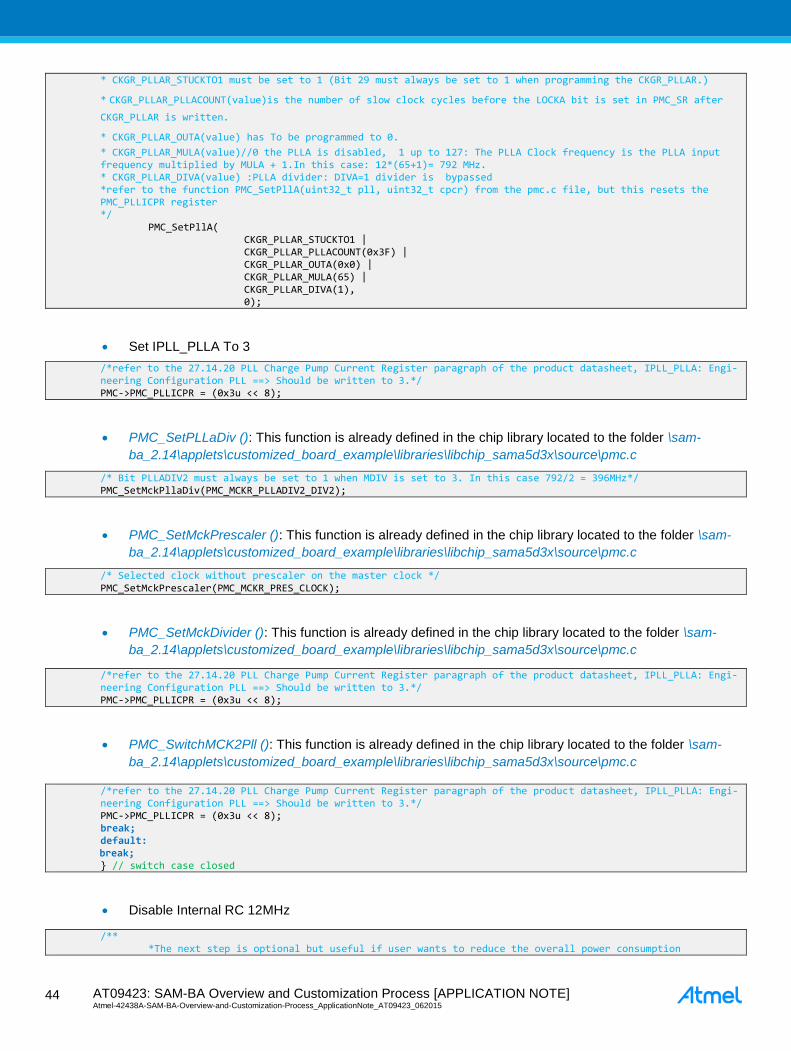
Set IPLL_PLLA To 3
PMC_SetPLLaDiv (): This function is already defined in the chip library located to the folder \sam-
ba_2.14\applets\customized_board_example\libraries\libchip_sama5d3x\source\pmc.c
PMC_SetMckPrescaler (): This function is already defined in the chip library located to the folder \sam-
ba_2.14\applets\customized_board_example\libraries\libchip_sama5d3x\source\pmc.c
PMC_SetMckDivider (): This function is already defined in the chip library located to the folder \sam-
ba_2.14\applets\customized_board_example\libraries\libchip_sama5d3x\source\pmc.c
PMC_SwitchMCK2Pll (): This function is already defined in the chip library located to the folder \sam-
ba_2.14\applets\customized_board_example\libraries\libchip_sama5d3x\source\pmc.c
Disable Internal RC 12MHz
* CKGR_PLLAR_STUCKTO1 must be set to 1 (Bit 29 must always be set to 1 when programming the CKGR_PLLAR.)
* CKGR_PLLAR_PLLACOUNT(value)is the number of slow clock cycles before the LOCKA bit is set in PMC_SR after
CKGR_PLLAR is written.
* CKGR_PLLAR_OUTA(value) has To be programmed to 0.
* CKGR_PLLAR_MULA(value)//0 the PLLA is disabled, 1 up to 127: The PLLA Clock frequency is the PLLA input frequency multiplied by MULA + 1.In this case: 12*(65+1)= 792 MHz. * CKGR_PLLAR_DIVA(value) :PLLA divider: DIVA=1 divider is bypassed *refer to the function PMC_SetPllA(uint32_t pll, uint32_t cpcr) from the pmc.c file, but this resets the PMC_PLLICPR register */
PMC_SetPllA( CKGR_PLLAR_STUCKTO1 | CKGR_PLLAR_PLLACOUNT(0x3F) | CKGR_PLLAR_OUTA(0x0) | CKGR_PLLAR_MULA(65) | CKGR_PLLAR_DIVA(1), 0);
/*refer to the 27.14.20 PLL Charge Pump Current Register paragraph of the product datasheet, IPLL_PLLA: Engi-neering Configuration PLL ==> Should be written to 3.*/ PMC->PMC_PLLICPR = (0x3u << 8);
/* Bit PLLADIV2 must always be set to 1 when MDIV is set to 3. In this case 792/2 = 396MHz*/ PMC_SetMckPllaDiv(PMC_MCKR_PLLADIV2_DIV2);
/* Selected clock without prescaler on the master clock */ PMC_SetMckPrescaler(PMC_MCKR_PRES_CLOCK);
/*refer to the 27.14.20 PLL Charge Pump Current Register paragraph of the product datasheet, IPLL_PLLA: Engi-neering Configuration PLL ==> Should be written to 3.*/ PMC->PMC_PLLICPR = (0x3u << 8);
/*refer to the 27.14.20 PLL Charge Pump Current Register paragraph of the product datasheet, IPLL_PLLA: Engi-neering Configuration PLL ==> Should be written to 3.*/ PMC->PMC_PLLICPR = (0x3u << 8); break; default:
break; // switch case closed
/** *The next step is optional but useful if user wants to reduce the overall power consumption

AT09423: SAM-BA Overview and Customization Process [APPLICATION NOTE] Atmel-42438A-SAM-BA-Overview-and-Customization-Process_ApplicationNote_AT09423_062015
45
45
Configure PCK1 to check MCK on scope
Reinitialize and check all the AIC interrupt flags
A finished and fully full implemented code is provided in Appendix A. This code provides the ability to select
several different frequencies as external input clock.
**/ /* disable internal RC 12 MHz*/ PMC->CKGR_MOR = (PMC->CKGR_MOR & ~CKGR_MOR_MOSCRCEN) | CKGR_MOR_KEY(0x37);
/** *The next step is optional but useful to check on scope if the MCK is correctly configured through PCK1 (PD31)
**/ /* Configure PCK1 to measure MCK */
PIOD->PIO_IDR = (1<<31); //Disable Interrupt on PD31 //abcdsr = PIOD->PIO_ABCDSR[0]; PIOD->PIO_ABCDSR[0] |= (1<<31); //enable the Peripheral B function which is PCK1 //abcdsr = PIOD->PIO_ABCDSR[1];
PIOD->PIO_ABCDSR[1] &= ~(1<<31); //enable the Peripheral B function which is PCK1 PIOD->PIO_PDR = (1<<31); /* Disable programmable clock 1 output */ REG_PMC_SCDR = PMC_SCDR_PCK1; //Disable the PCK1 output before using it /* Enable the DAC master clock */ PMC->PMC_PCK[1] = PMC_PCK_CSS_MCK_CLK | PMC_PCK_PRES_CLOCK; // Select the master clock (MCK) to connect it to the PCK1 without prescaler. /* Enable programmable clock 1 output */ REG_PMC_SCER = PMC_SCER_PCK1; //Enable the PCK1 output before using it /* Wait for the PCKRDY1 bit to be set in the PMC_SR register*/ while ((REG_PMC_SR & PMC_SR_PCKRDY1) == 0);
/**
*The next step is mandatory to be sure that no interrupt will hit during the communication with
SAM-BA
**/
/* select FIQ */
AIC->AIC_SSR = 0;
AIC->AIC_SVR = (unsigned int) defaultFiqHandler;
for (i = 1; i < 31; i++)
AIC->AIC_SSR = i;
AIC->AIC_SVR = (unsigned int) defaultIrqHandler;
AIC->AIC_SPU = (unsigned int) defaultSpuriousHandler;
/* Disable all interrupts */
for (i = 1; i < 31; i++)
AIC->AIC_SSR = i;
AIC->AIC_IDCR = 1 ;
/* Clear All pending interrupts flags */
for (i = 1; i < 31; i++)
AIC->AIC_SSR = i;
AIC->AIC_ICCR = 1 ;
/* Perform 8 IT acknowledge (write any value in EOICR) */
for (i = 0; i < 8 ; i++)
AIC->AIC_EOICR = 0;

AT09423: SAM-BA Overview and Customization Process [APPLICATION NOTE] Atmel-42438A-SAM-BA-Overview-and-Customization-Process_ApplicationNote_AT09423_062015 4
6
46
7.3 Customize an External Memory Applet
The most frequent customization required is when users decide to change the external RAM or the NAND
Flash device of their system. This section/subsections explains the main steps to perform to be able to
customize the different kinds of memories. As the customization is to modify existing applets only, this method
is an introduction for how to identify the main files to be modified and their related locations.
7.3.1 External Memory Customization Process Overview
Because the existing applet already provides the main initialization sequence used to send these parameters
to the external memory, the main goal is to modify this existing applet, making it compliant with the new
external RAM characteristics. Whatever the external RAM memory is, the main functions/parameters to take
care are summarized in Table 7-1.
Table 7-1. Customization Table
Parameter’s name/function Filename Directory Functionality
TCL scripts
variable extRamVdd customized_board_example.tcl sam-ba_2.14\tcl_lib\customized_board_example\ External Ram Memory Power Supply
Voltage (1.8V or 3.3V)
variable extRamType customized_board_example.tcl sam-ba_2.14\tcl_lib\customized_board_example\ External Ram Memory Type (SDRAM,
DDR, DDR2, LPDDR, LPDDR2)
variable extRamDataBusWidth customized_board_example.tcl sam-ba_2.14\tcl_lib\customized_board_example\ External Ram Memory Data Bus Width
(16-bit or 32-bit)
variable extDDRamModel customized_board_example.tcl sam-ba_2.14\tcl_lib\customized_board_example\ External Ram Memory Model (usually
refers to devices used with Atmel eval-
uation kits)
SDR/DDR initialization Applet file
Definition
#define BOARD_SDRAM_SIZE
main.c sam-ba_2.14\applets\customized_board_exam-
ple\sam-ba_applets\extram\
Board DDRAM size
Definition
#define SDRAM 0
#define DDRAM 1
#define LPDDR 2
main.c sam-ba_2.14\applets\customized_board_exam-
ple\sam-ba_applets\extram\
DDRAM type
Function Implementation Library file SDR/DDR initialization
Function
void BOARD_ConfigureDdram
(uint8_t device)
board_memories.c sam-ba_2.14\applets\customized_board_exam-
ple\libraries\libboard_sama5d3x-ek\source\
Configures DDR
Function
void BOARD_Config-
ureLpDdram (void)
board_memories.c sam-ba_2.14\applets\customized_board_exam-
ple\libraries\libboard_sama5d3x-ek\source\
Configures LPDDR
void BOARD_ConfigureSdram
(void)
board_memories.c sam-ba_2.14\applets\customized_board_exam-
ple\libraries\libboard_sama5d3x-ek\source\
Configures SDR
Function Implementation Library file NAND FLASH initialization
void BOARD_Config-
ureNandFlash (uint8_t bus-
Width)
board_memories.c sam-ba_2.14\applets\customized_board_exam-
ple\libraries\libboard_sama5d3x-ek\source\
Configures the EBI for NandFlash ac-
cess
In the following sections the process for the customization of the different memory types is introduced in a step-
by-step guide. Table 7-1 is used as a reference to initialize the external memory.
7.3.2 Customization Files Overview
7.3.2.1 TCL Scripts
These files have already been introduced in Section 2.6.1 Customized_board_example.tcl Description.

AT09423: SAM-BA Overview and Customization Process [APPLICATION NOTE] Atmel-42438A-SAM-BA-Overview-and-Customization-Process_ApplicationNote_AT09423_062015
47
47
7.3.2.2 SDR/DDR Initialization Applet File
This file is the main.c file located in the following directory:
sam-ba_2.14\applets\customized_board_example\sam-ba_applets\extram\.
This file is composed of several parts which will be briefly described in this section:
Headers: This part implement the libraries headers of the functions used in the main.c file
Definitions: These are the main constants used in the main.c file
Local structures: This part is where the applet mailbox is implemented. Structure for storing parameters
for each command that can be performed by the applet. All the parameters of this structure are used to
store the same parameters sent by the tcl scripts.
Global variables: This part is where the global variables are declared.
Local Functions
– static unsigned char ExtRAM_TestOk(void)
Go/No-Go test of the first 10KB of external RAM access
– int main(int argc, char **argv)
Applet main entry. This function decodes the received command and executes it.
During the customization process, several parts can be modified such as the definitions and the main function.
7.3.2.3 SDR/DDR Initialization Library File
This is the board_memories.c located into the sam-
ba_2.14\applets\customized_board_example\libraries\libboard_sama5d3x-ek\source\ directory.
This file is where all the functions related to the memories initializations are implemented.
This file is composed of the same kind of parts as the previous file but contains the following functions:
void BOARD_ConfigureDdram (uint8_t device)
void BOARD_ConfigureLpDdram (void)
void BOARD_ConfigureSdram (void)
void BOARD_ConfigureNandFlash (uint8_t busWidth)
void BOARD_ConfigureNorFlash (uint8_t busWidth)
In case of a customization, the main parameters to change to fit with the new memory AC characteristics are in
these functions.
7.3.3 SDR/DDR Customization Example
The following example is a SAM-BA customization for a DDR2 external memory.
Find the related datasheet of the device (external_DDR2_device.pdf) in the folder named “Datasheet”. The
device part number is XXXXXXKB25I and the speed grade (5-5-5 or 6-6-6).
The process introduced in this example can be reproduced for all the memory applets already available in
SAM-BA.
7.3.3.1 Step 1: Customize the customized_board_example.tcl
Open the customized_board_example.tcl file located in the sam-
ba_2.14\tcl_lib\customized_board_example\ directory.
Modify the BOARD Specific Parameters according to the datasheet of the device: extRamVdd,
extRamType, extRamDataBusWidth, extDDRamModel (introduced in Section 2.6.1
Customized_board_example.tcl Description).

AT09423: SAM-BA Overview and Customization Process [APPLICATION NOTE] Atmel-42438A-SAM-BA-Overview-and-Customization-Process_ApplicationNote_AT09423_062015 4
8
48
From the device datasheet we learn that the external memory is a 1Gb DDR2 memory organized in 8.388.608
words x 8 Banks x 16 bits. Its power supply is 1.8V.
The Board specific parameters have to be modified as follow:
################################################################################
## BOARD SPECIFIC PARAMETERS
################################################################################
namespace eval BOARD
variable sramSize $AT91C_IRAM_SIZE
variable maxBootSize 65328
# Default setting for DDRAM
# Vdd Memory 1.8V = 0 / Vdd Memory 3.3V = 1
variable extRamVdd 0
# External SDRAM = 0 / External DDR2 = 1 / LPDDR = 2
variable extRamType 1
# Set bus width (16 or 32)
variable extRamDataBusWidth 16
# DDRAM Model (0: MT47H64M16HR, 1: MT47H128M16RT, 3:W971GGKB
variable extDDRamModel 2
7.3.3.2 Step 2: Customize the SDR/DDR Initialization Applet File: main.c
Open the main.c file located in the sam-ba_2.14\applets\customized_board_example\sam-
ba_applets\extram\ directory
In the definition part, the new memory and the new BOARD_DDRAM_CUSTO_SIZE have to be defined
as shown (line 46 up to 61): /*----------------------------------------------------------------------------
* Definitions
*----------------------------------------------------------------------------*/
/* DDRAM type */
#define MT47H64M16HR 0
#define MT47H128M16RT 1
#define LPDDR 2
#define W971GGKB 3
/* Board DDRAM size*/
#define BOARD_DDRAM_SIZE_0 (64*1024*1024) // 64 MB
#define BOARD_DDRAM_SIZE_1 (128*1024*1024) // 128 MB
#define BOARD_SDRAM_SIZE (32*1024*1024) // 32 MB
#define BOARD_DDRAM_CUSTO_SIZE (64*1024*1024) // 64 MB
No other customization is required in this file as all the functions required are called as described:
/*----------------------------------------------------------------------------
* Local functions
*----------------------------------------------------------------------------*/
/**
* \brief Applet main entry. This function decodes received command and executes it.
*
* \param argc always 1
* \param argv Address of the argument area..
*/
int main(int argc, char **argv)
struct _Mailbox *pMailbox = (struct _Mailbox *) argv;
uint32_t comType = pMailbox->argument.inputInit.comType;
/* INIT: */
if (pMailbox->command == APPLET_CMD_INIT)
/* Save communication link type */
WDT->WDT_MR = WDT_MR_WDDIS;
#if (DYN_TRACES == 1)
//dwTraceLevel = 0;
#endif
#if (TRACE_LEVEL==0) && (DYN_TRACES==1)
if (comType == DBGU_COM_TYPE)

AT09423: SAM-BA Overview and Customization Process [APPLICATION NOTE] Atmel-42438A-SAM-BA-Overview-and-Customization-Process_ApplicationNote_AT09423_062015
49
49
/* Function TRACE_CONFIGURE_ISP will be bypass due to the 0 TRACE_LEVEL. We
shall reconfigure the baud rate. */
DBGU->DBGU_MR = DBGU_MR_CHMODE_NORM | DBGU_MR_PAR_NONE;
/* Reset and disable receiver & transmitter */
DBGU->DBGU_CR = DBGU_CR_RSTRX | DBGU_CR_RSTTX;
DBGU->DBGU_IDR = 0xFFFFFFFF;
DBGU->DBGU_CR = DBGU_CR_RSTRX | DBGU_CR_RSTTX | DBGU_CR_RXDIS | DBGU_CR_TXDIS;
/* Configure baudrate */
DBGU->DBGU_BRGR = (BOARD_MCK / 115200) / 16;
/* Enable receiver and transmitter */
DBGU->DBGU_CR = DBGU_CR_RXEN | DBGU_CR_TXEN;
#endif
//TRACE_INFO("-- EXTRAM Applet %s --\n\r", SAM_BA_APPLETS_VERSION);
//TRACE_INFO("-- %s\n\r", BOARD_NAME);
//TRACE_INFO("-- Compiled: %s %s --\n\r", __DATE__, __TIME__);
//TRACE_INFO("INIT command:\n\r");
//TRACE_INFO("\tCommunication link type : %lu\n\r", pMailbox->argument.in-
putInit.comType);
//TRACE_INFO("\tInit EBI Vdd : %s\n\r", (pMailbox->argument.inputInit.VddMem-
Sel)?"3.3V":"1.8V");
//BOARD_ConfigureVddMemSel(pMailbox->argument.inputInit.VddMemSel);
/* Configure DDRAM controller */
if ( pMailbox->argument.inputInit.ramType == 0)
//TRACE_INFO("\tExternal RAM type : %s\n\r", "SDRAM");
BOARD_ConfigureSdram();
pMailbox->argument.outputInit.memorySize = BOARD_SDRAM_SIZE;
else if ( pMailbox->argument.inputInit.ramType == 2)
/* Disable DDR clock. */
PMC->PMC_PCDR1 |= (1 << (ID_MPDDRC-32));
PMC->PMC_SCDR |= PMC_SCER_DDRCK;
BOARD_ConfigureLpDdram();
pMailbox->argument.outputInit.memorySize = BOARD_DDRAM_SIZE_0;
else
/* DDR reset */
MPDDRC->MPDDRC_LPR = MPDDRC_LPR_LPCB_DEEP_PWD |MPDDRC_LPR_CLK_FR_ENABLED;
/* Disable DDR clock. */
PMC->PMC_PCDR1 |= (1 << (ID_MPDDRC-32));
PMC->PMC_SCDR |= PMC_SCER_DDRCK;
//TRACE_INFO("\tExternal RAM type : %s\n\r", "DDRAM");
BOARD_ConfigureDdram(pMailbox->argument.inputInit.ddrModel);
if (pMailbox->argument.inputInit.ddrModel == MT47H64M16HR)
pMailbox->argument.outputInit.memorySize = BOARD_DDRAM_SIZE_0;
if (pMailbox->argument.inputInit.ddrModel == MT47H128M16RT)
pMailbox->argument.outputInit.memorySize = BOARD_DDRAM_SIZE_1;
/* Test external RAM access */
if (ExtRAM_TestOk())
pMailbox->status = APPLET_SUCCESS;
else
pMailbox->status = APPLET_FAIL;
pMailbox->argument.outputInit.bufferAddress = ((uint32_t) &_end);
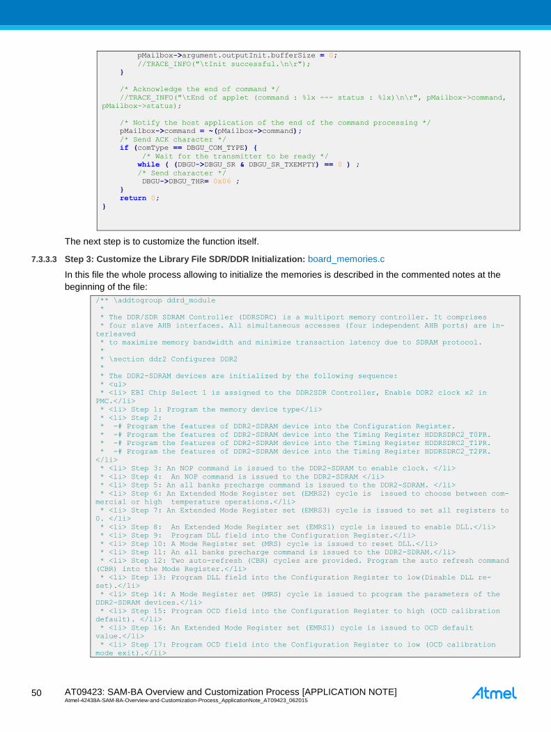
AT09423: SAM-BA Overview and Customization Process [APPLICATION NOTE] Atmel-42438A-SAM-BA-Overview-and-Customization-Process_ApplicationNote_AT09423_062015 5
0
50
pMailbox->argument.outputInit.bufferSize = 0;
//TRACE_INFO("\tInit successful.\n\r");
/* Acknowledge the end of command */
//TRACE_INFO("\tEnd of applet (command : %lx --- status : %lx)\n\r", pMailbox->command,
pMailbox->status);
/* Notify the host application of the end of the command processing */
pMailbox->command = ~(pMailbox->command);
/* Send ACK character */
if (comType == DBGU_COM_TYPE)
/* Wait for the transmitter to be ready */
while ( (DBGU->DBGU_SR & DBGU_SR_TXEMPTY) == 0 ) ;
/* Send character */
DBGU->DBGU_THR= 0x06 ;
return 0;
The next step is to customize the function itself.
7.3.3.3 Step 3: Customize the Library File SDR/DDR Initialization: board_memories.c
In this file the whole process allowing to initialize the memories is described in the commented notes at the
beginning of the file:
/** \addtogroup ddrd_module
*
* The DDR/SDR SDRAM Controller (DDRSDRC) is a multiport memory controller. It comprises
* four slave AHB interfaces. All simultaneous accesses (four independent AHB ports) are in-
terleaved
* to maximize memory bandwidth and minimize transaction latency due to SDRAM protocol.
*
* \section ddr2 Configures DDR2
*
* The DDR2-SDRAM devices are initialized by the following sequence:
* <ul>
* <li> EBI Chip Select 1 is assigned to the DDR2SDR Controller, Enable DDR2 clock x2 in
PMC.</li>
* <li> Step 1: Program the memory device type</li>
* <li> Step 2:
* -# Program the features of DDR2-SDRAM device into the Configuration Register.
* -# Program the features of DDR2-SDRAM device into the Timing Register HDDRSDRC2_T0PR.
* -# Program the features of DDR2-SDRAM device into the Timing Register HDDRSDRC2_T1PR.
* -# Program the features of DDR2-SDRAM device into the Timing Register HDDRSDRC2_T2PR.
</li>
* <li> Step 3: An NOP command is issued to the DDR2-SDRAM to enable clock. </li>
* <li> Step 4: An NOP command is issued to the DDR2-SDRAM </li>
* <li> Step 5: An all banks precharge command is issued to the DDR2-SDRAM. </li>
* <li> Step 6: An Extended Mode Register set (EMRS2) cycle is issued to choose between com-
mercial or high temperature operations.</li>
* <li> Step 7: An Extended Mode Register set (EMRS3) cycle is issued to set all registers to
0. </li>
* <li> Step 8: An Extended Mode Register set (EMRS1) cycle is issued to enable DLL.</li>
* <li> Step 9: Program DLL field into the Configuration Register.</li>
* <li> Step 10: A Mode Register set (MRS) cycle is issued to reset DLL.</li>
* <li> Step 11: An all banks precharge command is issued to the DDR2-SDRAM.</li>
* <li> Step 12: Two auto-refresh (CBR) cycles are provided. Program the auto refresh command
(CBR) into the Mode Register.</li>
* <li> Step 13: Program DLL field into the Configuration Register to low(Disable DLL re-
set).</li>
* <li> Step 14: A Mode Register set (MRS) cycle is issued to program the parameters of the
DDR2-SDRAM devices.</li>
* <li> Step 15: Program OCD field into the Configuration Register to high (OCD calibration
default). </li>
* <li> Step 16: An Extended Mode Register set (EMRS1) cycle is issued to OCD default
value.</li>
* <li> Step 17: Program OCD field into the Configuration Register to low (OCD calibration
mode exit).</li>

AT09423: SAM-BA Overview and Customization Process [APPLICATION NOTE] Atmel-42438A-SAM-BA-Overview-and-Customization-Process_ApplicationNote_AT09423_062015
51
51
* <li> Step 18: An Extended Mode Register set (EMRS1) cycle is issued to enable OCD
exit.</li>
* <li> Step 19,20: A mode Normal command is provided. Program the Normal mode into Mode Reg-
ister.</li>
* <li> Step 21: Write the refresh rate into the count field in the Refresh Timer register.
The DDR2-SDRAM device requires a refresh every 15.625 or 7.81. </li>
* </ul>
*/
/*@*/
/*@*/
/** \addtogroup sdram_module
*
* \section sdram Configures SDRAM
*
* The SDR-SDRAM devices are initialized by the following sequence:
* <ul>
* <li> EBI Chip Select 1 is assigned to the DDR2SDR Controller, Enable DDR2 clock x2 in
PMC.</li>
* <li> Step 1. Program the memory device type into the Memory Device Register</li>
* <li> Step 2. Program the features of the SDR-SDRAM device into the Timing Register and into
the Configuration Register.</li>
* <li> Step 3. For low-power SDRAM, temperature-compensated self refresh (TCSR), drive
strength (DS) and partial array self refresh (PASR) must be set in the Low-power Regis-
ter.</li>
* <li> Step 4. A NOP command is issued to the SDR-SDRAM. Program NOP command into Mode Regis-
ter, the application must
* set Mode to 1 in the Mode Register. Perform a write access to any SDR-SDRAM address to
acknowledge this command.
* Now the clock which drives SDR-SDRAM device is enabled.</li>
* <li> Step 5. An all banks precharge command is issued to the SDR-SDRAM. Program all banks
precharge command into Mode Register, the application must set Mode to 2 in the
* Mode Register . Perform a write access to any SDRSDRAM address to acknowledge this com-
mand.</li>
* <li> Step 6. Eight auto-refresh (CBR) cycles are provided. Program the auto refresh command
(CBR) into Mode Register, the application must set Mode to 4 in the Mode Register.
* Once in the idle state, two AUTO REFRESH cycles must be performed.</li>
* <li> Step 7. A Mode Register set (MRS) cycle is issued to program the parameters of the
SDRSDRAM
* devices, in particular CAS latency and burst length. </li>
* <li> Step 8. For low-power SDR-SDRAM initialization, an Extended Mode Register set (EMRS)
cycle is issued to program the SDR-SDRAM parameters (TCSR, PASR, DS). The write
* address must be chosen so that BA[1] is set to 1 and BA[0] is set to 0 </li>
* <li> Step 9. The application must go into Normal Mode, setting Mode to 0 in the Mode Regis-
ter and perform a write access at any location in the SDRAM to acknowledge this command.</li>
* <li> Step 10. Write the refresh rate into the count field in the DDRSDRC Refresh Timer reg-
ister </li>
* </ul>
*/
/*@*/
/*@*/
This is exactly what is implemented into the functions themselves, as described in the following example (only
the first 10 steps introduced…):
void BOARD_ConfigureDdram( uint8_t device )
volatile uint8_t *pDdr = (uint8_t *) DDR_CS_ADDR;
volatile uint32_t i;
volatile uint32_t cr = 0;
volatile uint32_t dummy_value;
#if 1
dummy_value = 0x00000000;
/* Enable DDR2 clock x2 in PMC */
PMC->PMC_PCER1 = (1 << (ID_MPDDRC-32));
PMC->PMC_SCER |= PMC_SCER_DDRCK;
MPDDRC->MPDDRC_LPR = 0;
*(uint32_t *)0xFFFFEA24 |= (1 << 5); // DDRSDRC High Speed Register (MPDDRC_HS) : hidden
option -> calibration during autorefresh

AT09423: SAM-BA Overview and Customization Process [APPLICATION NOTE] Atmel-42438A-SAM-BA-Overview-and-Customization-Process_ApplicationNote_AT09423_062015 5
2
52
*(uint32_t *)0xF0038004 |= (0x3 << 16); // SFR_DDRCFG DDR Configuration Force DDR_DQ
and DDR_DQS input buffer always on
MPDDRC->MPDDRC_DLL_SOR = MPDDRC_DLL_SOR_S0_OFF(0x1) | MPDDRC_DLL_SOR_S1_OFF(0x0) |
MPDDRC_DLL_SOR_S2_OFF(0x1) | MPDDRC_DLL_SOR_S3_OFF(0x1);
MPDDRC->MPDDRC_DLL_MOR = (0xC5000000) | MPDDRC_DLL_MOR_MOFF(7) |
MPDDRC_DLL_MOR_CLK90OFF(0x1F) | MPDDRC_DLL_MOR_SELOFF; // Key = 0xc5000000
dummy_value = MPDDRC->MPDDRC_IO_CALIBR;
dummy_value &= ~MPDDRC_IO_CALIBR_RDIV_Msk;
dummy_value &= ~MPDDRC_IO_CALIBR_TZQIO_Msk;
dummy_value |= MPDDRC_IO_CALIBR_RDIV_RZQ_48;
dummy_value |= MPDDRC_IO_CALIBR_TZQIO(3);
MPDDRC->MPDDRC_IO_CALIBR = dummy_value;
*(uint32_t *)0xF0038004 = (0x3 << 16); // SFR_DDRCFG DDR Configuration Force DDR_DQ and
DDR_DQS input buffer always on
#endif
/* Step 1: Program the memory device type */
/* DBW = 0 (32 bits bus wide); Memory Device = 6 = DDR2-SDRAM = 0x00000006*/
MPDDRC->MPDDRC_MD = MPDDRC_MD_MD_DDR2_SDRAM;
/* Step 2: Program the features of DDR2-SDRAM device into the Timing Register.*/
if (device == MT47H128M16RT)
MPDDRC->MPDDRC_CR = MPDDRC_CR_NR(3) |
MPDDRC_CR_NC(1) |
MPDDRC_CR_CAS(4) |
MPDDRC_CR_NB_8 |
MPDDRC_CR_DLL_RESET_DISABLED |
MPDDRC_CR_DQMS_NOT_SHARED |
MPDDRC_CR_ENRDM_OFF |
MPDDRC_CR_UNAL_SUPPORTED |
MPDDRC_CR_NDQS_DISABLED |
MPDDRC_CR_OCD(0x0);
if (device == MT47H64M16HR)
MPDDRC->MPDDRC_CR = MPDDRC_CR_NR(2) |
MPDDRC_CR_NC(1) |
MPDDRC_CR_CAS(3)|
MPDDRC_CR_NB_8 |
MPDDRC_CR_DLL_RESET_DISABLED |
MPDDRC_CR_DQMS_NOT_SHARED |
MPDDRC_CR_ENRDM_OFF |
MPDDRC_CR_UNAL_SUPPORTED |
MPDDRC_CR_NDQS_DISABLED |
MPDDRC_CR_OCD(0x0);
MPDDRC->MPDDRC_TPR0 = MPDDRC_TPR0_TRAS(6) // 6 * 7.5 = 45 ns
| MPDDRC_TPR0_TRCD(2) // 2 * 7.5 = 15 ns
| MPDDRC_TPR0_TWR(2) // 3 * 7.5 = 22.5 ns
| MPDDRC_TPR0_TRC(8) // 8 * 7.5 = 60 ns
| MPDDRC_TPR0_TRP(2) // 2 * 7.5 = 15 ns
| MPDDRC_TPR0_TRRD(1) // 2 * 7.5 = 15 ns
| MPDDRC_TPR0_TWTR(2) // 2 clock cycle
| MPDDRC_TPR0_TMRD(2); // 2 clock cycles
MPDDRC->MPDDRC_TPR1 = MPDDRC_TPR1_TRFC(14) // 18 * 7.5 = 135 ns (min 127.5 ns for 1Gb
DDR)
| MPDDRC_TPR1_TXSNR(16) // 20 * 7.5 > 142.5ns TXSNR: Exit self re-
fresh delay to non read command
| MPDDRC_TPR1_TXSRD(208) // min 200 clock cycles, TXSRD: Exit self re-
fresh delay to Read command
| MPDDRC_TPR1_TXP(2); // 2 * 7.5 = 15 ns
MPDDRC->MPDDRC_TPR2 = MPDDRC_TPR2_TXARD(7) // min 2 clock cycles
| MPDDRC_TPR2_TXARDS(7)// min 7 clock cycles
| MPDDRC_TPR2_TRPA(2) // min 18ns
| MPDDRC_TPR2_TRTP(2) // 2 * 7.5 = 15 ns (min 7.5ns)
| MPDDRC_TPR2_TFAW(10) ;
/* DDRSDRC Low-power Register */

AT09423: SAM-BA Overview and Customization Process [APPLICATION NOTE] Atmel-42438A-SAM-BA-Overview-and-Customization-Process_ApplicationNote_AT09423_062015
53
53
for (i = 0; i < 13300; i++)
asm("nop");
MPDDRC->MPDDRC_LPR = MPDDRC_LPR_LPCB_DISABLED | MPDDRC_LPR_CLK_FR_DISABLED |
MPDDRC_LPR_TIMEOUT_0 | MPDDRC_LPR_APDE_FAST;
/* Step 3: An NOP command is issued to the DDR2-SDRAM. Program the NOP command into
the Mode Register, the application must set MODE to 1 in the Mode Register. */
MPDDRC->MPDDRC_MR = MPDDRC_MR_MODE_NOP_CMD;
/* Perform a write access to any DDR2-SDRAM address to acknowledge this command */
*pDdr = 0; /* Now clocks which drive DDR2-SDRAM device are enabled.*/
/* A minimum pause of 200 is provided to precede any signal toggle. (6 core cycles per
iteration, core is at 396MHz: min 13200 loops) */
for (i = 0; i < 13300; i++)
asm("nop");
/* Step 4: An NOP command is issued to the DDR2-SDRAM */
MPDDRC->MPDDRC_MR = MPDDRC_MR_MODE_NOP_CMD;
/* Perform a write access to any DDR2-SDRAM address to acknowledge this command.*/
*pDdr = 0; /* Now CKE is driven high.*/
/* wait 400 ns min */
for (i = 0; i < 100; i++)
asm("nop");
/* Step 5: An all banks precharge command is issued to the DDR2-SDRAM. */
MPDDRC->MPDDRC_MR = MPDDRC_MR_MODE_PRCGALL_CMD;
/* Perform a write access to any DDR2-SDRAM address to acknowledge this command.*/
*pDdr = 0;
/* wait 400 ns min */
for (i = 0; i < 100; i++)
asm("nop");
/* Step 6: An Extended Mode Register set (EMRS2) cycle is issued to choose between commercial
or high temperature operations. */
MPDDRC->MPDDRC_MR = MPDDRC_MR_MODE_EXT_LMR_CMD;
*((uint8_t *)(pDdr + DDR2_BA1(device))) = 0; /* The write address must be chosen so that
BA[1] is set to 1 and BA[0] is set to 0. */
/* wait 2 cycles min */
for (i = 0; i < 100; i++)
asm("nop");
/* Step 7: An Extended Mode Register set (EMRS3) cycle is issued to set all registers to 0. */
MPDDRC->MPDDRC_MR = MPDDRC_MR_MODE_EXT_LMR_CMD;
*((uint8_t *)(pDdr + DDR2_BA1(device) + DDR2_BA0(device))) = 0; /* The write address must
be chosen so that BA[1] is set to 1 and BA[0] is set to 1.*/
/* wait 2 cycles min */
for (i = 0; i < 100; i++)
asm("nop");
/* Step 8: An Extended Mode Register set (EMRS1) cycle is issued to enable DLL. */
MPDDRC->MPDDRC_MR = MPDDRC_MR_MODE_EXT_LMR_CMD;
*((uint8_t *)(pDdr + DDR2_BA0(device))) = 0; /* The write address must be chosen so that
BA[1] is set to 0 and BA[0] is set to 1. */
/* An additional 200 cycles of clock are required for locking DLL */
for (i = 0; i < 10000; i++)
asm("nop");
/* Step 9: Program DLL field into the Configuration Register.*/
cr = MPDDRC->MPDDRC_CR;
MPDDRC->MPDDRC_CR = cr | MPDDRC_CR_DLL_RESET_ENABLED;
/* Step 10: A Mode Register set (MRS) cycle is issued to reset DLL. */
MPDDRC->MPDDRC_MR = MPDDRC_MR_MODE_LMR_CMD;
*(pDdr) = 0; /* The write address must be chosen so that BA[1:0] bits are set to 0. */
/* wait 2 cycles min */
for (i = 0; i < 100; i++)

AT09423: SAM-BA Overview and Customization Process [APPLICATION NOTE] Atmel-42438A-SAM-BA-Overview-and-Customization-Process_ApplicationNote_AT09423_062015 5
4
54
asm("nop");
…..
……..
…..
Regarding the customization purpose, the main modifications, which have to be considered, are the external
memory timing and architecture parameters, introduced in step 2. In the board_memories.c file, the existing
implementation is related to the Atmel Evaluation Kits. These code lines can be copied or/and modified to just
fit to the external memory.
/* Step 2: Program the features of DDR2-SDRAM device into the Timing Register.*/
MPDDRC->MPDDRC_CR = MPDDRC_CR_NR(2) |
MPDDRC_CR_NC(1) |
MPDDRC_CR_CAS(3)|
MPDDRC_CR_NB_8 |
MPDDRC_CR_DLL_RESET_DISABLED |
MPDDRC_CR_DQMS_NOT_SHARED |
MPDDRC_CR_ENRDM_OFF |
MPDDRC_CR_UNAL_SUPPORTED |
MPDDRC_CR_NDQS_DISABLED |
MPDDRC_CR_OCD(0x0);
MPDDRC->MPDDRC_TPR0 = MPDDRC_TPR0_TRAS(6) // 6 * 7.5 = 45 ns
| MPDDRC_TPR0_TRCD(2) // 2 * 7.5 = 15 ns
| MPDDRC_TPR0_TWR(2) // 3 * 7.5 = 22.5 ns
| MPDDRC_TPR0_TRC(8) // 8 * 7.5 = 60 ns
| MPDDRC_TPR0_TRP(2) // 2 * 7.5 = 15 ns
| MPDDRC_TPR0_TRRD(1) // 2 * 7.5 = 15 ns
| MPDDRC_TPR0_TWTR(2) // 2 clock cycle
| MPDDRC_TPR0_TMRD(2); // 2 clock cycles
MPDDRC->MPDDRC_TPR1 = MPDDRC_TPR1_TRFC(14) // 18 * 7.5 = 135 ns (min 127.5 ns for 1Gb
DDR)
| MPDDRC_TPR1_TXSNR(16) // 20 * 7.5 > 142.5ns TXSNR: Exit self re-
fresh delay to non read command
| MPDDRC_TPR1_TXSRD(208) // min 200 clock cycles, TXSRD: Exit self
refresh delay to Read command
| MPDDRC_TPR1_TXP(2); // 2 * 7.5 = 15 ns
MPDDRC->MPDDRC_TPR2 = MPDDRC_TPR2_TXARD(7) // min 2 clock cycles
| MPDDRC_TPR2_TXARDS(7)// min 7 clock cycles
| MPDDRC_TPR2_TRPA(2) // min 18ns
| MPDDRC_TPR2_TRTP(2) // 2 * 7.5 = 15 ns (min 7.5ns)
| MPDDRC_TPR2_TFAW(10) ;
The main difficulty here is to identify and make this implementation matching with the parameters introduced
from the external memory datasheet.
Let’s have a look at this process with the previous example (external_DDR2_device.pdf).
The customization principle will be to fill the matching values (between the parentheses) according to the value
required by the external memory identified into its own datasheet.
/* Step 2: Program the features of DDR2-SDRAM device into the Timing Register.*/
MPDDRC->MPDDRC_CR = MPDDRC_CR_NR() | MPDDRC_CR_NC() | MPDDRC_CR_CAS() | MPDDRC_CR_NB_8 | MPDDRC_CR_DLL_RESET_DISABLED | MPDDRC_CR_DQMS_NOT_SHARED | MPDDRC_CR_ENRDM_OFF | MPDDRC_CR_UNAL_SUPPORTED | MPDDRC_CR_NDQS_DISABLED | MPDDRC_CR_OCD();
MPDDRC->MPDDRC_TPR0 = MPDDRC_TPR0_TRAS() | MPDDRC_TPR0_TRCD() | MPDDRC_TPR0_TWR()

AT09423: SAM-BA Overview and Customization Process [APPLICATION NOTE] Atmel-42438A-SAM-BA-Overview-and-Customization-Process_ApplicationNote_AT09423_062015
55
55
| MPDDRC_TPR0_TRC() | MPDDRC_TPR0_TRP() | MPDDRC_TPR0_TRRD() | MPDDRC_TPR0_TWTR() | MPDDRC_TPR0_TMRD();
MPDDRC->MPDDRC_TPR1 = MPDDRC_TPR1_TRFC() | MPDDRC_TPR1_TXSNR() | MPDDRC_TPR1_TXSRD() | MPDDRC_TPR1_TXP();
MPDDRC->MPDDRC_TPR2 = MPDDRC_TPR2_TXARD() | MPDDRC_TPR2_TXARDS() | MPDDRC_TPR2_TRPA() | MPDDRC_TPR2_TRTP() | MPDDRC_TPR2_TFAW();
Mainly two different parameter families are to be customized:
The “Memory Configuration” parameters:
– CAS Latency
– Number of Rows
– Number of Columns
the timings parameters
All these parameters are related to only a few registers of the SAMA5 (or other Atmel MPU):
The “memory architecture” parameters have to be set into the MPDDRC_CR register (MPDDRC
Configuration Register)
The timings parameters have to be set into the MPDDRC Timing Parameter 0, 1, 2 Registers
(MPDDRC_TPR0, MPDDRC_TPR1, MPDDRC_TPR2)
From the memory datasheet, all the parameters are described and introduced across the datasheet. Normally
the timings are summarized into the table “AC Characteristics” and the CAS latency the number of row and
column, directly from the “General Description”.
Find the related datasheet of the device (external_DDR2_device.pdf) in the folder named “Datasheet”. The
device part number is XXXXXXKB25I and the speed grade (5-5-5 or 6-6-6).
Regarding the “memory architecture” parameters, let’s have a look at the different field of the register
MPDDRC_CR:

AT09423: SAM-BA Overview and Customization Process [APPLICATION NOTE] Atmel-42438A-SAM-BA-Overview-and-Customization-Process_ApplicationNote_AT09423_062015 5
6
56
MPDDRC_CR Register view
Using the datasheet for the Atmel device and the datasheet for the external memory, the configuration
parameters have to be identified. The table below summarizes what are the functions of the different bit fields
of the MPDDRC_CR register and where the appropriate values can be found in the external memory
datasheet.
MPDDRC_CR bit-
field Function
Where is it in the external
memory datasheet Value to be set
NC Bits 0-1 Number of Column Bits in the ad-
dress bus
Ball Description: column address:
A0 – A9 10
NR Bits 2-3 Number of Column Bits in the ad-
dress bus
Ball Description: row address: A0 –
A12 13
CAS Bits 4-5-6 CAS latency General Description:
CAS Latency 3, 4, 5, 6, 7 3 (min)
DLL Bit 7
This bit defines the value of Reset
DLL. This bit is found only in the
DDR2-SDRAM devices
Digital Locked Loop, This is found
only in the DDR2-SDRAM devices
1 (Enable DLL
reset)
DIC_DS Bit 8
Output Driver Impedance Control
(Drive Strength).
This bit is found only in the DDR2-
SDRAM devices.
This bit name is described as
“DS” in some memory datasheets.
No DS found
0 (DDR2_NOR-
MAL-
STRENGTH)

AT09423: SAM-BA Overview and Customization Process [APPLICATION NOTE] Atmel-42438A-SAM-BA-Overview-and-Customization-Process_ApplicationNote_AT09423_062015
57
57
MPDDRC_CR bit-
field Function
Where is it in the external
memory datasheet Value to be set
DIS_DLL Bit 9
DISABLE DLL
This value is used during the
power-up sequence. It is only
found in the DDR2-SDRAM de-
vices.
Digital Locked Loop, This is found
only in the DDR2-SDRAM de-
vices.
0
Enable the DLL
(let the reset
value)
ZQ Bit 10 – 11
ZQ Calibration: This parameter is
used to calibrate DRAM On re-
sistance (Ron) values over PVT
This field is found only in the low-
power DDR2-SDRAM devices.
N.A. (let at the
reset value)
OCD Bit 12 – 13
- 14
Off Chip Driver
This field is found only in the
DDR2-SDRAM devices.
SDRAM Controller supports only
two values for OCD (default cali-
bration and exit from calibration).
These values MUST always be
programmed during the initializa-
tion sequence. The default cali-
bration must be programmed first.
After which the exit calibration
and maintain settings must be
programmed. See step 12 Of the
Functional Description
7
DDR2_DE-
FAULT_CALIB
and 0
DDR2_EXIT-
CALIB after the
initialization.
DQMS Bit 16 Mask Data is Shared DQM is not shared with another
controller
0
NOT_SHARED
ENRDM Bit 17 Enable Read Measure Not necessary 0
OFF
NB Bit 20 Number of Banks General description 1
8-banks
NDQS Bit 21 This bit is found only in the DDR2-
SDRAM devices.
Extend Mode Register Set Com-
mands (EMRS)
0
Disabled
DECOD Bit 22 Type of Decoding Sequential is mandatory
0
SEQUENTIAL
(let the reset
value)
UNAL Bit 23 Support Unaligned Access
General Description / Feature
Edge-aligned with Read data and
center-aligned with the Write data
0
Not supported
Therefore the step 2 can be completed as below:
/* Step 2: Program the features of DDR2-SDRAM device into the Timing Register.*/
MPDDRC->MPDDRC_CR = MPDDRC_CR_NR(13) | MPDDRC_CR_NC(10) | MPDDRC_CR_CAS(3) | MPDDRC_CR_NB_8 | MPDDRC_CR_DLL_RESET_ENABLED | MPDDRC_CR_DQMS_NOT_SHARED | MPDDRC_CR_ENRDM_OFF | MPDDRC_CR_UNAL_UNSUPPORTED | MPDDRC_CR_NDQS_DISABLED | MPDDRC_CR_OCD(0x7);
Regarding the Timings, this time three different registers are used to store all the timings required to access
the external memory:

AT09423: SAM-BA Overview and Customization Process [APPLICATION NOTE] Atmel-42438A-SAM-BA-Overview-and-Customization-Process_ApplicationNote_AT09423_062015 5
8
58

AT09423: SAM-BA Overview and Customization Process [APPLICATION NOTE] Atmel-42438A-SAM-BA-Overview-and-Customization-Process_ApplicationNote_AT09423_062015
59
59
The timings configuration is obviously related to the bus clock frequency. In this case the DDR bus frequency
provided by MCK is considered to be 133MHz, which gives a 7.52ns time period.
MPDDRC_TPx bitfield Function Where is it in the external memory
datasheet
Value to
be set
MPDDRC_TPR0_TRAS
Active To pre-charge Delay: delay
between an Activate command and
a pre-charge command in number
of SDCK clock cycles
AC Characteristics and Operating
Condition:
TRAS: Active to Pre-charge Com-
mand Period
45ns min.
MPDDRC_TPR0_TRCD
Row to Column Delay: delay be-
tween an Activate command and a
Read/Write command in number of
SDCK clock cycles.
AC Characteristics and Operating
Condition:
TRCD: Active to Read/Write Com-
mand Delay time
12.5ns
min.
MPDDRC_TPR0_TWR
Write Recovery Delay: Write Recov-
ery Time in number of SDCK clock
cycles.
AC Characteristics and Operating
Condition:
TWR: Write recovery Time
15ns
MPDDRC_TPR0_TRC
Row Cycle Delay: delay between an
Activate command and Refresh
command in number of SDCK clock
cycles
AC Characteristics and Operating
Condition:
TRC: Active to Refresh/Active com-
mand Period
57.5ns
min.
MPDDRC_TPR0_TRP
Row Pre-charge Delay: delay be-
tween a pre-charge command and
another command in number of
SDCK clock cycles
AC Characteristics and Operating
Condition:
TRP: Pre-charge to active command
period
12.5 ns
min

AT09423: SAM-BA Overview and Customization Process [APPLICATION NOTE] Atmel-42438A-SAM-BA-Overview-and-Customization-Process_ApplicationNote_AT09423_062015 6
0
60
MPDDRC_TPx bitfield Function Where is it in the external memory
datasheet
Value to
be set
MPDDRC_TPR0_TRRD
Active Bank A to Active Bank B: de-
lay between an Activate command
in Bank A and an Activate com-
mand in Bank B in number of SDCK
clock cycles
AC Characteristics and Operating
Condition:
TRRD: Active to active command pe-
riod for 2KB page size
10ns
MPDDRC_TPR0_TWTR
Internal Write to Read Delay: inter-
nal Write to Read command time in
number of SDCK clock cycles
AC Characteristics and Operating
Condition:
TWTR: Internal write to read com-
mand delay
7.5ns
MPDDRC_TPR0_RDC_
WRRD
Reduce Write to Read Delay: delay
between write to read access for the
low-power DDR-SDRAM devices
with a latency equal to 2. To use
this feature, the TWTR field must be
equal to 0. Note that some devices
do not support this feature.
AC Characteristics and Operating
Condition:
Not Supported
N-A
MPDDRC_TPR0_TMRD
Load Mode Register Command to
Activate or Refresh Command: de-
lay between a Load mode register
command and an Activate or Re-
fresh command in number of SDCK
clock cycles.
AC Characteristics and Operating
Condition:
TMRD: Mode Register set command
cycle time
2 clock
cycles
MPDDRC_TPR1_TXP
Exit Power-down Delay to First
Command: delay between CKE set
high and a Valid command in num-
ber of SDCK clock cycles
AC Characteristics and Operating
Condition:
TXP: Exit pre-charge power down to
any command
2 clock
cycles
MPDDRC_TPR1_TXSRD
Exit Self-refresh Delay to Read
Command: delay between CKE set
high and a Read command in num-
ber of SDCK clock cycles
AC Characteristics and Operating
Condition:
TXSRD: Self refresh to read com-
mand
200 clock
cycles
MPDDRC_TPR1_TXSNR
Exit Self-refresh Delay to Non Read
Command: delay between CKE set
high and a Non Read command in
number of SDCK clock cycles
AC Characteristics and Operating
Condition:
TXSNR: Exit Self Refresh to a non-
Read command.
tRFC+10
= 137.5ns
min.
MPDDRC_TPR1_TRFC
Row Cycle Delay: Delay between a
Refresh command or a Refresh and
Activate command in number of
SDCK clock cycles.
IDD Measurement Test Parameter
and AC Characteristics and Operat-
ing Condition:
TRFC: Auto Refresh To Active/ Auto
Refresh command period
127.5ns
MPDDRC_TPR2_TFAW
Four Active Windows: DDR2 de-
vices with eight banks (1Gb or
larger) have an additional require-
ment concerning tFAW timing. This
requires that no more than four Acti-
vate commands may be issued in
any given tFAW (MIN) period. This
field is found only in the DDR2-
SDRAM and LPDDR2-SDRAM de-
vices
IDD Measurement Test Parameter
and AC Characteristics and Operat-
ing Condition:
Four Activate Window for 2KB page
size.
45ns

AT09423: SAM-BA Overview and Customization Process [APPLICATION NOTE] Atmel-42438A-SAM-BA-Overview-and-Customization-Process_ApplicationNote_AT09423_062015
61
61
MPDDRC_TPx bitfield Function Where is it in the external memory
datasheet
Value to
be set
MPDDRC_TPR2_TRTP
Read to Pre-charge: This field de-
fines the delay between Read com-
mand and a Pre-charge command
in number of SDCK clock cycles
AC Characteristics and Operating
Condition:
TRTP: Internal Read to Pre-charge
command Delay.
7.5ns
MPDDRC_TPR2_TRPA
Row Pre-charge All Delay: This field
defines the delay between a Pre-
charge All Banks command and an-
other command in number of SDCK
clock cycles.
Burst read with Auto-Pre-charge:
TRP All
TRPALL=
TRP+1 x
TCK)
MPDDRC_TPR2_TXARD
S
Exit Active Power Down Delay to
Read Command in Mode “Slow
Exit”: delay between CKE set high
and a Read command in number of
SDCK clock cycles. This field is
found only in the DDR2-SDRAM de-
vices.
AC Characteristics and Operating
Condition:
TXARDS: Exit Active power own to
read command
10 clock
cycles
MPDDRC_TPR2_TXARD
Exit Active Power Down Delay to
Read Command in Mode “Fast
Exit”: delay between CKE set high
and a Read command in number of
SDCK clock cycles. This field is
found only in the DDR2-SDRAM de-
vices.
AC Characteristics and Operating
Condition:
Exit on Active power down to Read
command
3 clock
cycles
Step 2 can be completed as follow:
/* Step 2: Program the features of DDR2-SDRAM device into the Timing Register.*/
MPDDRC->MPDDRC_CR = MPDDRC_CR_NR(13) | MPDDRC_CR_NC(10) | MPDDRC_CR_CAS(3) | MPDDRC_CR_NB_8 | MPDDRC_CR_DLL_RESET_ENABLED | MPDDRC_CR_DQMS_NOT_SHARED | MPDDRC_CR_ENRDM_OFF | MPDDRC_CR_UNAL_UNSUPPORTED | MPDDRC_CR_NDQS_DISABLED | MPDDRC_CR_OCD(0x7);
MPDDRC->MPDDRC_TPR0 = MPDDRC_TPR0_TRAS(6) // 6 * 7.5 = 45 ns
| MPDDRC_TPR0_TRCD(2) // 2 * 7.5 = 15 ns
| MPDDRC_TPR0_TWR(2) // 3 * 7.5 = 22.5 ns
| MPDDRC_TPR0_TRC(8) // 8 * 7.5 = 60 ns
| MPDDRC_TPR0_TRP(2) // 2 * 7.5 = 15 ns
| MPDDRC_TPR0_TRRD(1) // 2 * 7.5 = 15 ns
| MPDDRC_TPR0_TWTR(2) // 2 clock cycle
| MPDDRC_TPR0_TMRD(2); // 2 clock cycles
MPDDRC->MPDDRC_TPR1 = MPDDRC_TPR1_TRFC(14) // 18 * 7.5 = 135 ns (min 127.5 ns for 1Gb DDR)
| MPDDRC_TPR1_TXSNR(16) // 20 * 7.5 > 142.5ns
|MPDDRC_TPR1_TXSRD(208) // min 200 clock cycles,
| MPDDRC_TPR1_TXP(2); // 2 * 7.5 = 15 ns
MPDDRC->MPDDRC_TPR2 = MPDDRC_TPR2_TXARD(7) // min 2 clock cycles
| MPDDRC_TPR2_TXARDS(7)// min 7 clock cycles
| MPDDRC_TPR2_TRPA(2) // min 18ns
| MPDDRC_TPR2_TRTP(2) // 2 * 7.5 = 15 ns (min 7.5ns)
| MPDDRC_TPR2_TFAW(10) ;

AT09423: SAM-BA Overview and Customization Process [APPLICATION NOTE] Atmel-42438A-SAM-BA-Overview-and-Customization-Process_ApplicationNote_AT09423_062015 6
2
62
8 Compile the SAM-BA Applets and Test Your Modifications
At this moment, the applets are customized, and the tools required to compile them are already installed. Let’s
start with the applet compilation by using:
Sourcery CodeBench Lite 2012.09-63 for ARM EABI
GNU make 3.81
GNU Core utils 5.3
Before compiling the modified applets, the make file has to be updated accordingly to the new board
(my_training_board) entry name and directory in order to update the existing binary file in the \Atmel\sam-
ba_2.14\tcl_lib\my_training_board directory.
Go to the modified applet path: Atmel\sam-ba_2.14\applets\my_training_board\sam-ba_applets\lowlevelinit
and open the make file in a text editor:
Replace the code line #34 “BOARD = at91sama5d3x-ek” by “BOARD = my_customized_board”
Replace the code line #40 “BOARD_DIR= at91sama5d3x-ek” by “BOARD_DIR = my_customized_board” as
described below: (my_training_board or my_customized_board)
Save your modifications
The make file will update the applet binary file in the C:\Program Files (x86)\Atmel\sam-
ba_2.14\tcl_lib\my_training_board directory.
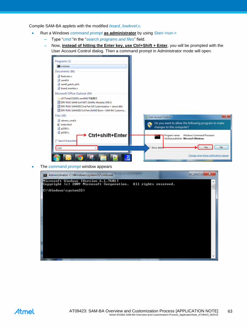
AT09423: SAM-BA Overview and Customization Process [APPLICATION NOTE] Atmel-42438A-SAM-BA-Overview-and-Customization-Process_ApplicationNote_AT09423_062015
63
63
Compile SAM-BA applets with the modified board_lowlevel.c.
Run a Windows command prompt as administrator by using Start->run->
– Type “cmd “in the “search programs and files” field.
– Now, instead of hitting the Enter key, use Ctrl+Shift + Enter, you will be prompted with the
User Account Control dialog. Then a command prompt in Administrator mode will open.
The command prompt window appears

AT09423: SAM-BA Overview and Customization Process [APPLICATION NOTE] Atmel-42438A-SAM-BA-Overview-and-Customization-Process_ApplicationNote_AT09423_062015 6
4
64
Go to the ”C:\Program Files (x86)\Atmel\sam-ba_2.12\applets\my_training_board\sam-
ba_applets\lowlevelinit” by using the command:
cd ”C:\Program Files (x86)\Atmel\sam-ba_2.12\applets\my_training_board\sam-ba_applets\lowlevelinit”
Type the command make and press enter:
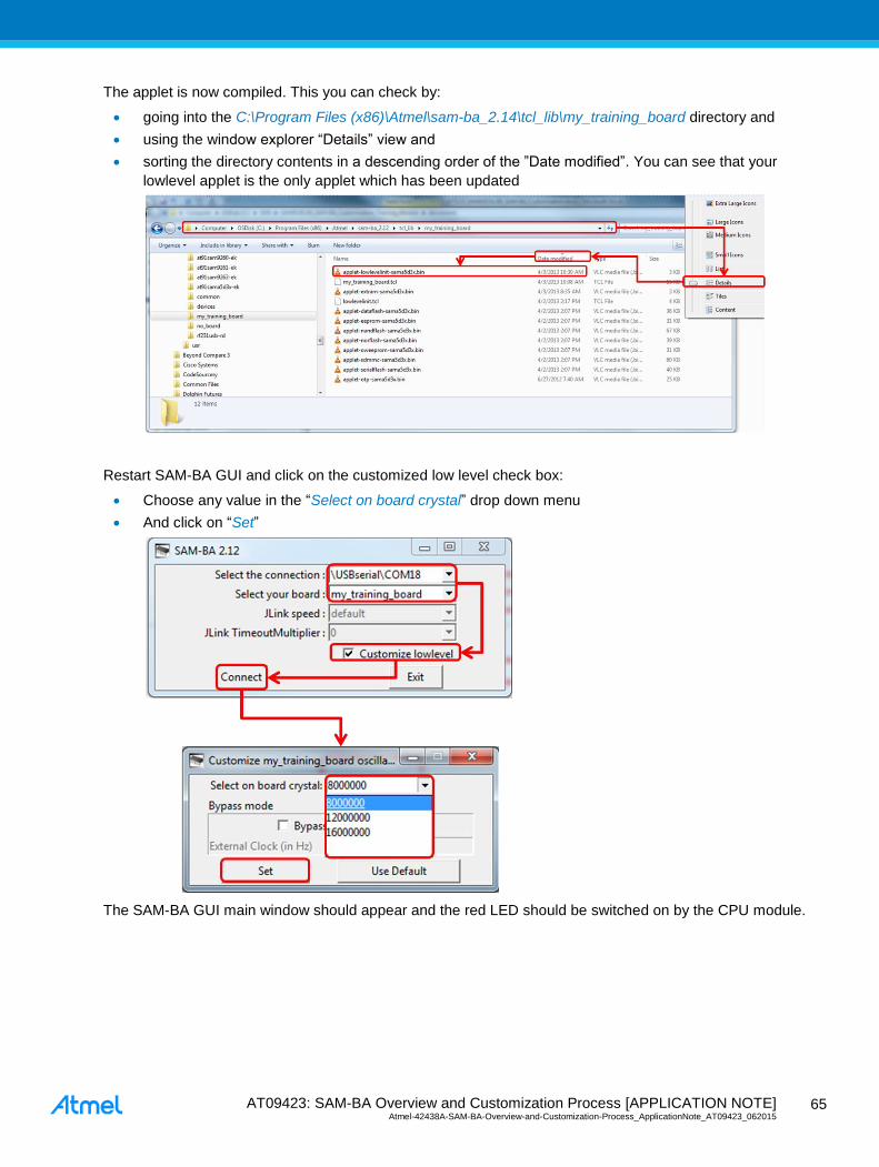
AT09423: SAM-BA Overview and Customization Process [APPLICATION NOTE] Atmel-42438A-SAM-BA-Overview-and-Customization-Process_ApplicationNote_AT09423_062015
65
65
The applet is now compiled. This you can check by:
going into the C:\Program Files (x86)\Atmel\sam-ba_2.14\tcl_lib\my_training_board directory and
using the window explorer “Details” view and
sorting the directory contents in a descending order of the ”Date modified”. You can see that your
lowlevel applet is the only applet which has been updated
Restart SAM-BA GUI and click on the customized low level check box:
Choose any value in the “Select on board crystal” drop down menu
And click on “Set”
The SAM-BA GUI main window should appear and the red LED should be switched on by the CPU module.

AT09423: SAM-BA Overview and Customization Process [APPLICATION NOTE] Atmel-42438A-SAM-BA-Overview-and-Customization-Process_ApplicationNote_AT09423_062015 6
6
66

AT09423: SAM-BA Overview and Customization Process [APPLICATION NOTE] Atmel-42438A-SAM-BA-Overview-and-Customization-Process_ApplicationNote_AT09423_062015
67
67
9 References
Document Comments
sam-ba user guide.pdf User guide provided in the doc directory inside the SAM-BA installation directory
SAMA5D3x Product Datasheet Available on the Atmel website: http://www.atmel.com/products/microcontrol-
lers/arm/sama5.aspx?tab=documents
SAM-BA Customization Hands-on This training is shared on request. It is also included inside this application note
final package.

AT09423: SAM-BA Overview and Customization Process [APPLICATION NOTE] Atmel-42438A-SAM-BA-Overview-and-Customization-Process_ApplicationNote_AT09423_062015 6
8
68
Appendix A Full Implementation of the Bypass Mode /**
* \brief Configure the PMC in bypass mode. An external clock should be input to XIN as the source clock.
*
* \param extClk The frequency of the external clock
*/
static void bypass_LowLevelInit (uint32_t extClk)
/* First Switch the MCK to the main clock oscillator */
PMC_SwitchMck2Main();
/* enable external OSC 12 MHz bypass */
PMC->CKGR_MOR = (PMC->CKGR_MOR | CKGR_MOR_MOSCXTBY) | CKGR_MOR_KEY(0x37);
/* switch MAIN clock to external OSC */
PMC->CKGR_MOR |= CKGR_MOR_MOSCSEL | CKGR_MOR_KEY(0x37);
/* wait MAIN clock status change for external OSC 12 MHz selection*/
while(!(PMC->PMC_SR & PMC_SR_MOSCSELS));
/* in case where MCK is running on MAIN CLK */
while(!(PMC->PMC_SR & PMC_SR_MCKRDY));
/**
* The PLLA configuration will depend on the extClk value which represents the frequency of the external
clock signal.
* In this case we have to configure for any value to have the PLLA well configured.
* As a reminder of the PLL electrical characteristics:
* - Fout (the output frequency) must be in a range between 400 MHz and 800MHz (in worst case)
* - Fin (the input Frequency) must be in a range between 8MHz and 50 MHz
* - t (start-up time) must be in a range between 25 us and 100 us.
**/
switch (extClk)
/* When external clock frequency is 12MHz */
case 12000000:
PMC_SetPllA( CKGR_PLLAR_STUCKTO1 | //this bit must be set to 1 (Bit 29 must always be set to
1 when programming the CKGR_PLLAR.)
CKGR_PLLAR_PLLACOUNT(0x3F) | //this bit-field is the number of slow clock cycles before the
LOCKA bit is set in PMC_SR after CKGR_PLLAR is written.
CKGR_PLLAR_OUTA(0x0) | //To be programmed to 0.
CKGR_PLLAR_MULA(65) | //0 the PLLA is disabled, 1 up to 127: The PLLA Clock fre-
quency is the PLLA input frequency multiplied by MULA + 1.
//In this case: 12*(65+1)= 792 MHz
CKGR_PLLAR_DIVA(1), //PLLA divider: DIVA=1 divider is bypassed
0); // refer to the function PMC_SetPllA(uint32_t pll, uint32_t
cpcr) from the pmc.c file, but this resets the PMC_PLLICPR register
PMC->PMC_PLLICPR = (0x3u << 8); //refer to the 27.14.20 PLL Charge Pump Current Register para-
graph of the product datasheet, IPLL_PLLA: Engineering Configuration PLL ==> Should be written to 3.
PMC_SetMckPllaDiv(PMC_MCKR_PLLADIV2_DIV2); //Bit PLLADIV2 must always be set to 1 when MDIV is set to 3.
//In this case 792/2 = 396MHz
PMC_SetMckPrescaler(PMC_MCKR_PRES_CLOCK); //Selected clock without prescaler on the master clock
PMC_SetMckDivider(PMC_MCKR_MDIV_PCK_DIV3); //Master Clock is Prescaler Output Clock divided by 3.
//Finally we get 396/3= 132MHz as final frequency
PMC_SwitchMck2Pll(); //MCK is now switched on the PLLA. MCK =132MHz.
break;
/* When external clock frequency is 16MHz */
case 16000000:
PMC_SetPllA( CKGR_PLLAR_STUCKTO1 | //this bit must be set to 1 (Bit 29 must always be set to 1
when programming the CKGR_PLLAR.)
CKGR_PLLAR_PLLACOUNT(0x3F) | //this bitfield is the number of slow clock cycles before the
LOCKA bit is set in PMC_SR after CKGR_PLLAR is written.
CKGR_PLLAR_OUTA(0x0) | //To be programmed to 0.
CKGR_PLLAR_MULA(49) | //0 the PLLA is disabled, 1 up to 127: The PLLA Clock fre-
quency is the PLLA input frequency multiplied by MULA + 1.
//In this case: 16*(49+1)= 800 MHz
CKGR_PLLAR_DIVA(1), //PLLA divider: DIVA=1 divider is bypassed
0); //refer to the function PMC_SetPllA(uint32_t pll, uint32_t
cpcr) in the pmc.c file, but this resets the PMC_PLLICPR register
PMC->PMC_PLLICPR = (0x3u << 8); //refer to the 27.14.20 PLL Charge Pump Current Register para-
graph of the product datasheet, IPLL_PLLA: Engineering Configuration PLL ==> Should be written to 3.
PMC_SetMckPllaDiv(PMC_MCKR_PLLADIV2_DIV2); //Bit PLLADIV2 must always be set to 1 when MDIV is set to 3.

AT09423: SAM-BA Overview and Customization Process [APPLICATION NOTE] Atmel-42438A-SAM-BA-Overview-and-Customization-Process_ApplicationNote_AT09423_062015
69
69
//In this case 800/2 = 400MHz
PMC_SetMckPrescaler(PMC_MCKR_PRES_CLOCK); //Selected clock without prescaler on the master clock
PMC_SetMckDivider(PMC_MCKR_MDIV_PCK_DIV3); //Master Clock is Prescaler Output Clock divided by 3.
//Finally we get 400/3= 133.33333MHz as final frequency
PMC_SwitchMck2Pll(); //MCK is now switched on the PLLA. MCK =133.33333MHz.
break;
/* When external clock frequency is 19MHz */
case 19000000:
PMC_SetPllA( CKGR_PLLAR_STUCKTO1 | //this bit must be set to 1 (Bit 29 must always be set to 1
when programming the CKGR_PLLAR.)
CKGR_PLLAR_PLLACOUNT(0x3F) | //this bitfield is the number of slow clock cycles before the
LOCKA bit is set in PMC_SR after CKGR_PLLAR is written.
CKGR_PLLAR_OUTA(0x0) | //To be programmed to 0.
CKGR_PLLAR_MULA(40) | //0 the PLLA is disabled, 1 up to 127: The PLLA Clock fre-
quency is the PLLA input frequency multiplied by MULA + 1.
//In this case: 19*(40+1)= 779 MHz
CKGR_PLLAR_DIVA(1), //PLLA divider: DIVA=1 divider is bypassed
0); //refer to the function PMC_SetPllA(uint32_t pll, uint32_t
cpcr) in the pmc.c file, but this resets the PMC_PLLICPR register
PMC->PMC_PLLICPR = (0x3u << 8); //refer to the 27.14.20 PLL Charge Pump Current Register para-
graph of the product datasheet, IPLL_PLLA: Engineering Configuration PLL ==> Should be written to 3.
PMC_SetMckPllaDiv(PMC_MCKR_PLLADIV2_DIV2); //Bit PLLADIV2 must always be set to 1 when MDIV is set to 3.
//In this case 779/2 = 389.5MHz
PMC_SetMckPrescaler(PMC_MCKR_PRES_CLOCK); //Selected clock without prescaler on the master clock
PMC_SetMckDivider(PMC_MCKR_MDIV_PCK_DIV3); //Master Clock is Prescaler Output Clock divided by 3.
//Finally we get 389.5/3= 133MHz as final frequency
PMC_SwitchMck2Pll(); //MCK is now switched on the PLLA. MCK =129.8333MHz.
break;
/* When external clock frequency is 19MHz */
case 19200000:
PMC_SetPllA( CKGR_PLLAR_STUCKTO1 | //this bit must be set to 1 (Bit 29 must always be set to 1
when programming the CKGR_PLLAR.)
CKGR_PLLAR_PLLACOUNT(0x3F) | //this bitfield is the number of slow clock cycles before the
LOCKA bit is set in PMC_SR after CKGR_PLLAR is written.
CKGR_PLLAR_OUTA(0x0) | //To be programmed to 0.
CKGR_PLLAR_MULA(40) | //0 the PLLA is disabled, 1 up to 127: The PLLA Clock fre-
quency is the PLLA input frequency multiplied by MULA + 1.
//In this case: 19.2*(38+1)= 768 MHz
CKGR_PLLAR_DIVA(1), //PLLA divider: DIVA=1 divider is bypassed
0); //refer to the function PMC_SetPllA(uint32_t pll, uint32_t
cpcr) in the pmc.c file, but this resets the PMC_PLLICPR register
PMC->PMC_PLLICPR = (0x3u << 8); //refer to the 27.14.20 PLL Charge Pump Current Register para-
graph of the product datasheet, IPLL_PLLA: Engineering Configuration PLL ==> Should be written to 3.
PMC_SetMckPllaDiv(PMC_MCKR_PLLADIV2_DIV2); //Bit PLLADIV2 must always be set to 1 when MDIV is set to 3.
//In this case 768/2 = 384MHz
PMC_SetMckPrescaler(PMC_MCKR_PRES_CLOCK); //Selected clock without prescaler on the master clock
PMC_SetMckDivider(PMC_MCKR_MDIV_PCK_DIV3); //Master Clock is Prescaler Output Clock divided by 3.
//Finally we get 384/3= 128MHz as final frequency
PMC_SwitchMck2Pll(); //MCK is now switched on the PLLA. MCK =128MHz.
break;
/* When external clock frequency is 24MHz */
case 24000000:
PMC_SetPllA( CKGR_PLLAR_STUCKTO1 | //this bit must be set to 1 (Bit 29 must always be set to 1
when programming the CKGR_PLLAR.)
CKGR_PLLAR_PLLACOUNT(0x3F) | //this bitfield is the number of slow clock cycles before the
LOCKA bit is set in PMC_SR after CKGR_PLLAR is written.
CKGR_PLLAR_OUTA(0x0) | //To be programmed to 0.
CKGR_PLLAR_MULA(32) | //0 the PLLA is disabled, 1 up to 127: The PLLA Clock fre-
quency is the PLLA input frequency multiplied by MULA + 1.
//In this case: 24*(32+1)= 792 MHz
CKGR_PLLAR_DIVA(1), //PLLA divider: DIVA=1 divider is bypassed
0); //refer to the function PMC_SetPllA(uint32_t pll, uint32_t
cpcr) in the pmc.c file, but this resets the PMC_PLLICPR register
PMC->PMC_PLLICPR = (0x3u << 8); //refer to the 27.14.20 PLL Charge Pump Current Register para-
graph of the product datasheet, IPLL_PLLA: Engineering Configuration PLL ==> Should be written to 3.
PMC_SetMckPllaDiv(PMC_MCKR_PLLADIV2_DIV2); //Bit PLLADIV2 must always be set to 1 when MDIV is set to 3.
//In this case 792/2 = 396MHz
PMC_SetMckPrescaler(PMC_MCKR_PRES_CLOCK); //Selected clock without prescaler on the master clock
PMC_SetMckDivider(PMC_MCKR_MDIV_PCK_DIV3); //Master Clock is Prescaler Output Clock divided by 3.
//Finally we get 399/3= 133MHz as final frequency
PMC_SwitchMck2Pll(); //MCK is now switched on the PLLA. MCK =132MHz.

AT09423: SAM-BA Overview and Customization Process [APPLICATION NOTE] Atmel-42438A-SAM-BA-Overview-and-Customization-Process_ApplicationNote_AT09423_062015 7
0
70
break;
default:
break;
/**
* The next step is optional but useful if user wants to reduce the overall power consumption
**/
/* disable internal RC 12 MHz*/
PMC->CKGR_MOR = (PMC->CKGR_MOR & ~CKGR_MOR_MOSCRCEN) | CKGR_MOR_KEY(0x37);
/**
* The next step is optional but useful to check on scope if the MCK is correctly configured through PCK1
(PD31)
**/
/* Configure PCK1 to measure MCK */
PIOD->PIO_IDR = (1<<31); //Disable Interrupt on PD31
//abcdsr = PIOD->PIO_ABCDSR[0];
PIOD->PIO_ABCDSR[0] |= (1<<31); //enable the Peripheral B function
which is PCK1
//abcdsr = PIOD->PIO_ABCDSR[1];
PIOD->PIO_ABCDSR[1] &= ~(1<<31); //enable the Peripheral B function which is
PCK1
PIOD->PIO_PDR = (1<<31);
/* Disable programmable clock 1 output */
REG_PMC_SCDR = PMC_SCDR_PCK1; //Disable the PCK1 output before using
it
/* Enable the DAC master clock */
PMC->PMC_PCK[1] = PMC_PCK_CSS_MCK_CLK | PMC_PCK_PRES_CLOCK; // Select the master clock (MCK) to
connect it to the PCK1 without prescaler.
/* Enable programmable clock 1 output */
REG_PMC_SCER = PMC_SCER_PCK1; //Enable the PCK1 output before using
it
/* Wait for the PCKRDY1 bit to be set in the PMC_SR register*/
while ((REG_PMC_SR & PMC_SR_PCKRDY1) == 0); //
/**
* The next step is mandatory to be sure that no interrupt will hit during the communication with SAM-BA
**/
/* select FIQ */
AIC->AIC_SSR = 0;
AIC->AIC_SVR = (unsigned int) defaultFiqHandler;
for (i = 1; i < 31; i++)
AIC->AIC_SSR = i;
AIC->AIC_SVR = (unsigned int) defaultIrqHandler;
AIC->AIC_SPU = (unsigned int) defaultSpuriousHandler;
/* Disable all interrupts */
for (i = 1; i < 31; i++)
AIC->AIC_SSR = i;
AIC->AIC_IDCR = 1 ;
/* Clear All pending interrupts flags */
for (i = 1; i < 31; i++)
AIC->AIC_SSR = i;
AIC->AIC_ICCR = 1 ;
/* Perform 8 IT acknowledge (write any value in EOICR) */
for (i = 0; i < 8 ; i++)
AIC->AIC_EOICR = 0;

AT09423: SAM-BA Overview and Customization Process [APPLICATION NOTE] Atmel-42438A-SAM-BA-Overview-and-Customization-Process_ApplicationNote_AT09423_062015
71
71
Appendix B Revision History
Doc Rev. Date Comments
42438A 06/2015 Initial document release.
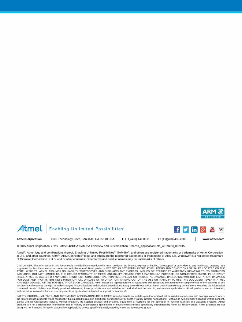
AT09423: SAM-BA Overview and Customization Process [APPLICATION NOTE] Atmel-42438A-SAM-BA-Overview-and-Customization-Process_ApplicationNote_AT09423_062015 7
2
72
Atmel Corporation 1600 Technology Drive, San Jose, CA 95110 USA T: (+1)(408) 441.0311 F: (+1)(408) 436.4200 www.atmel.com
© 2015 Atmel Corporation. / Rev.: Atmel-42438A-SAM-BA-Overview-and-Customization-Process_ApplicationNote_AT09423_062015. Atmel®, Atmel logo and combinations thereof, Enabling Unlimited Possibilities®, SAM-BA®, and others are registered trademarks or trademarks of Atmel Corporation in U.S. and other countries. ARM®, ARM Connected® logo, and others are the registered trademarks or trademarks of ARM Ltd. Windows® is a registered trademark of Microsoft Corporation in U.S. and or other countries. Other terms and product names may be trademarks of others.
DISCLAIMER: The information in this document is provided in connection with Atmel products. No license, express or implied, b y estoppel or otherwise, to any intellectual property right is granted by this document or in connection with the sale of Atmel products. EXCEPT AS SET FORTH IN THE ATMEL TERMS AND COND ITIONS OF SALES LOCATED ON THE ATMEL WEBSITE, ATMEL ASSUMES NO LIABILITY WHATSOEVER AND DISCLAIMS ANY EXPRESS, IMPLIED OR STATUTORY WARRANTY RELATING TO ITS PRODUCTS
INCLUDING, BUT NOT LIMITED TO, THE IMPLIED WARRANTY OF MERCHANTABILITY, FITNESS FOR A PARTICULAR PURPOSE, OR NON -INFRINGEMENT. IN NO EVENT SHALL ATMEL BE LIABLE FOR ANY DIRECT, INDIRECT, CONSEQUENTIAL, PUNITIVE, SPECIAL OR INCIDENTAL DAMAGES (INCLUDING, WITHOUT LIMITATION, DAMAGES FOR LOSS AND PROFITS, BUSINESS INTERRUPTION, OR LOSS OF INFORMATION) ARISING OUT OF THE USE OR INABILITY TO USE THIS DOCUMENT , EVEN IF ATMEL
HAS BEEN ADVISED OF THE POSSIBILITY OF SUCH DAMAGES. Atmel makes no representations or warranties with respect to the accuracy or completeness of the contents of this document and reserves the right to make changes to specifications and products descriptions at any time wi thout notice. Atmel does not make any commitment to update the information contained herein. Unless specifically provided otherwise, Atmel products are not suitable for, and shall not be used in, auto motive applications. Atmel products are not intended,
authorized, or warranted for use as components in applications intended to support or sustain life.
SAFETY-CRITICAL, MILITARY, AND AUTOMOTIVE APPLICATIONS DISCLAIMER: Atmel products are not designed for and will not be used in conne ction with any applications where the failure of such products would reasonably be expected to result in significant personal injury or death (“Safety -Critical Applications”) without an Atmel officer's specific written consent. Safety-Critical Applications include, without limitation, life support devices and systems, equipment or systems for the operation of nuclear facilities and weapons systems. Atmel
products are not designed nor intended for use in military or aerospace applications or environments unless specifically designated by Atmel as military-grade. Atmel products are not
designed nor intended for use in automotive applications unless specifically designated by Atmel as automotive -grade.