atomics international division - etec4073).pdf · atomics international division 8900 desoto avenue...
TRANSCRIPT


Atomics International Division 8900 DeSoto Avenue Canoga Park, California 91 304

This report has been distributed according to the category
"Waste Management," a s given in the Standard Distribution for
Unclassified Scientific and Technical Reports, TID-4500.


P a g e
Building 073 Cover . Vents. E lec t r i ca l Functions. . . . . . . . . . . . . . . . . . . . . . . . . . . . . . . . C o m p r e s s o r P a d 1
Roof of Building 073 C l e a r e of Cover ..........-...ofcover......................... 11
. . . . . . . . . . . . . . . . . . . . . . . . . . . . . . . . . Reac tor Enc losure 14
. . . . . . . . . . . . . . . . . . . . . . Reac tor Vesse l and Graphi te Logs 14
. . . . . . . . . . . . . . . . Reac tor Location After Enc losure Removal 16
. . . . . . . . . . . . . . . . . Location of Pr inc ipa l Sys t em Components 16
. . . . . . . . . . . . . . . . . . . Contaminated P ipe Removal by Coring 18
. . . . . . . . . . . . . . . . . . . . . P i t L iner F r o m Fue l Handling Room 18
. . . . . . . . . . . . . . . . . . . . . . Waste Storage Building Demolition 20
. . . . . . . . . . . . Radioactive Waste Holdup Tanks After Excavation 21
. . . . . . . . . . . . . . . . . . . . . . . . . . Hoe-Ram Breaking Concre te 22
. . . . . . . . . . . . . . . . . . . . . . . . . . . . . . . . Hoe-Ram Operat ion 22
. . . . . . . . . . . . . . . Demolition of Conc re t e Roof of Reac tor Room 23
. . . . . . . . . . . . . . . . . . . . . . . Demolition Cont rac tor Activit ies 23
. . . . . . . . . . . . . . . . . . . . . . . . Fina l Grading Over KEWB A r e a 24
Activated Concre te Removal F r o m West Wall . . . . . . . . . . . . . . . . . . . . . . . . . . . . . . . . . . o f R e a c t o r R o o m 28

reactor vessel,
rotective systems


The Kinetics Ex er iment Water Boiler (KEWB) reactor was l a s t operated
and the sys tem r insed in 1968. Radiological
en performed until the dismantling of the facility
a r y 1975. T e KEWB facili t ies were declared excess and
the dismantling proceeded a s described in the Decontamination and Disposition
of Faci l i t ies P r o g r a m Plan, PP-704-990-002.
The KEWB facili t ies, a s shown in F igures 1 and 2, were decontaminated,
ismantled, a n the s i te graded to blend with the surrounding terrain. The
cil i t ies consisted of e Reactor Tes t Building 073, the Exhaust Blower Build-
ing 643, the Electr ical Control Building 793, and the Waste Storage Building
123. The KEWB facility a l so included a 1000-gal. liquid waste holdup tank, a
1000-gal, reac tor cooling water s torage tank, and a 300-gal. gaseous waste
tank. The tanks and associated piping were located underground near Build-
73 (Figure 3).
Buildings 643, 93, and 123 were completely demolished, including r e -
moval of concrete footings and pads. All contaminated o r activated equipment
and mater ia l s w e r e removed f rom Building 073 and sent to the A1 Radioactive
Materials Disposal Facili ty (RMDF) for decontamination and disposal for unre-
s t r ic ted use, o r packaged for shipment to Beatty, Nevada for burial. The
ove-grade s t ruc tu res and the roof of Building 073 (Figures 4 and 5) were
demolished. The remaining concrete floor and walls were decontaminated to
levels which were as low as practicable (ALAP), but in a l l cases below those
leve Is es tab lis he as acceptable for future unrestr ic ted use of the s i te ,
i s repor t summarizes the m o r e pertinent decontamination and disposi-
s s e s special techniques used, and reviews major
i r resolution,

VALVE GALLERY
CHANGE AREA
BLDG 073 K.E.W.B. TEST BLDG EXCLUSION AREA
FUEL STORAGE
7704-62354
Figure 1. KEWB Facilities

7704-62355
Figure 2, KEWB Area and Facilities

COOLING WATER 12" STACK GO'HIGH HOLD UP TANK
1000 GALLONS
SH WATER HOLD-UP TANK 00 GALLONS
'L Z ~ ~ D R A ~ N L I N E - / 4 I
\ 11-21 -55 AE29-5704
F igure 3. KEWB Support Facili t ies
Figure 4. Building 073 Cover, Vents, E lec t r ica l Functions, and Compressor Pad

9072-7
F i g u r e 5 , Roof of Building 073 Cleared of Cove r


Phys i ca l d ismant l ing of the KEWB fac i l i t i e s began on J anua ry 17, 1975, but
w a s discontinue a week l a t e r when the dismant l ing c r e w w a s reass igned to a
r p r i o r i t y D&D effort. T h e D&D of the KEWB w a s begun again on Apr i l 7,
and w a s completed on June 27, 1975.
A KEWB Dismant l ing P l a n (Appendix A) which defined the scope of the dis - mantling effor t was p repared . This p lan was reviewed and approved by the
Isotopes Commit tee of the A1 Nuc lea r Safeguards Review Pane1 and subsequently
approved by ERDA. A deta i led working procedure ' ' ) was then p r epa red which p ro -
vided s tep-by-s tep del ineat ion of the t asks desc r ibed i n the Dismantl ing Plan. This
p rocedu re was a l s o reviewed, and approved by the Isotopes Commit tee .
T h e work was per fo rmed by the A1 Remote Technology Unit No. 731-540,
which cons i s t s of personnel t r a i ned t o work with radioact ive m a t e r i a l s . Continu-
ous consulting suppor t w a s provided by a f o r m e r KEWB opera to r . Health, Safety
and Radiation Se rv i ce s (HSRS), Indus t r i a l Engineering, and the Maintenance
Depar tment provided a s s i s t a n c e a s required. A demoli t ion con t r ac to r was h i r ed
t o b r e a k up t he concre te , d ig out t he tanks , and backfi l l and g rade t h e excavation.
Health physics su rve i l l ance was provided during a l l ac t iv i t ies .
A. PREPA
The exis t ing personne l change room a t t he e n t r y t o Building 073 was reac t i -
vated and resuppl ied , An HSRS work stat ion, equipped with radiat ion counting
i n s t r m e n t a t i o n , was s e t up in t he E l ec t r i c a l Control Building No, 793. P e r s o n -
ne l dos im e te r s , por table radia t ion su rvey ins t rumentat ion, breathing appara tus ,
a i r s a m p l e r s , and protect ive clothing w e r e provided in the change room. Resu l t s
iation and contarnination su rveys of the KEWB a r e a a r e shown in Table 4,
eginning the D&D act iv i t ies , a l l pe r sonne l a s soc i a t ed with the d i s -
r iefed by the unit m a n a g e r on t he scope of t he work, the
radiat ion h a z ec ted, and t he safe ty precaut ions requ i red . A f ami l i a r i z a -
t ion rev iew o p rocedures and t he reequirements f o r l imit ing personnel
o l eve l s which a r e a s Low a s p rac t i cab le ,as e s c r i bed in Re fe r ence
the unit m a n a

9070-6210
F i g u r e 6. R e a c t o r Enc l o s u r e
9304-5422
F i g u r e 7. Reac to r V e s s e l and Graph i t e Logs

B, PROCEDURES
The Detailed Working P rocedu re s descr ibed the work and established the
sequence of d ismant l ing s teps . Where deviations we re neczs sa ry , thcy w e r e
noted on the Work Copy of the procedures.
Extraneous equipment and m a t e r i a l s such a s doors , f i l i. c a h i n ~ ~ t ~ , :< l~c~ lv r &- ,
r acks , benches , and nonuseable protect ive clo%ing were removed frorrl Ir3uililii:g
073. E l ec t r i c a l pDwer, except f o r l ights, was disconnc.ctcd by Maintenkn-;.,
Compressed a i r l ines and t he empty wash water s o rage tank wrrc- rclnoved
f rom the valve ga l le ry room.
1.
The overhead wir ing and cable t r a y s and the hot wate r h e a t e r s w e r e r e -
moved, surveyed, and sent to salvage, The control rod d r ~ v e s and controls
w e r e removed , surveyed, and placed rn con ta iners for shrpment Lo a burral si te,
The nor th and wes t p la tes of the r eac to r enc losure (F igure 6 ) w e r e unbolted
to pe rmi t r emova l of the graphi te logs which surrounded the r eac to r v e s s e l
(F igure 7 shows par t i a l ly d i sassembled log pile) .
A s m e a r survey of the graphi te logs in.dicated removable contamination 2 2
l eve l s ranging f r o m 100 dpm/100 c m ,B to 30,135 dpm/100 cm ,El, and f rom 2 2
20 dpm/lOO cm ff to 12,000 dprn/lOO cm Q, Radiation levels a t the sur face of
the graphi te logs , a s m e a s u r e d with a por table ins t rument , ranged f rom 10
m R / h r to 150 m R / h r . Six of the graphi te logs located d i rec t ly beneath the r e -
a c to r v e s s e l on the f loor of the enc losure w e r e coataminated with what ap-
peared to b e u r an ium sa l t s , All graphi te logs w e r e wrapped in plas t ic sheet
tagged a s radioact ive was te , and t r a n s f e r r e d to the .EMDF for fi-nal packaging
and shipment to Beatty, Nevada f o r bur ia l , Ai r s amp le s taken dur ing the -12 graphi te log r emova l indicated a i rbo rne contamination leve l s of 9,9 x 10
-12 . ,ci/cc,B and 1.2 x 10 C l / c c ~ ,
Af te r removal of the logs , a l l pipe l ~ n e s lo the r eac to r ve s se l w e r ? cri-rrped
to contarn any res rdues and then cut with a saw. A srnear survey of the r eac to r
v e s s e l ex te rna l su r f ace lndrcated removable beta contanlrnatron levels rangrrrg 2
f rom 360 to 40,555 dpm/lOO crn . The ves se l was sp ray parntecl to f r x the con-
tamination and then removed, wrapped in plas t ic (55 gal . bag), and placed in a

V A U L T DOOR
DISTILLING CONDENSER
FUEL MIXING BOWL
9070-6273 F igu re 8. Reactor Location After
Enc losure Removal.
WASH WATER T A N K
TEST CORE
REFLECTOR
SECONDARY ENCLOSURE
REACTIVITY MECHANISM
0 1 2 3 4 u
SCALE, ft.
7704-62357
Figu re 9, Location of Pr inc ipa l System Components.

shipping container and sent to Beatty, Nevada for burial. A maximum of
300 m R / h r was measured a t the surface of the vessel. The maximum radiation
dose received by m e m b e r s of the dismantling crew was 20 mrem. Air sam-
ples taken during the reac tor removal indicated no a i rborne contamination 3 3
grea ter than 1 x 1 0 - ~ ~ ~ C i / c m o r 1 x 1 0 - ~ ~ ~ ~ i / c m (1, which is approxi-
mately the level of natural a i rborne activity a t the Santa Susana site.
The remainder of the reac tor enclosure was cut out using a welding m a -
chine and a carbon rod. Airborne activity observed during this operation was -1 1
a l so l e s s than 1 x 10 pCi/ccf l and 1 x l ~ - ~ ~ ~ ~ i / c c a . Smear surveys of
the reactor room floor indicated removable contamination levels of l e s s than 2
50 dpm/100 crn P. The reac tor enclosure s t ructure was placed in boxes for
shipment to Beatty, Nevada for burial. Smear surveys of the concrete pad
elow the reac tor , and the concrete wall adjacent to the reactor (see
r e 8) revealed no removable contamination. However, concrete samples
f rom these a r e a s did indicate induced radioactivity. The levels of induced
activity observed a r e shown in Tables 1 , 2 and 3. All concrete containing
detectable induced activity was subsequently removed, so that ALAP levels
became the natural radiation level of the concrete , a s established by sampling
unir radiated concrete f rom building walls outside the reac tor room.
2.
The Fuel Handling Room contained the process sys tems for controlling,
mixing, monitoring, and storing of the reactor fuel. Valve controls w e r e
extended through the 2-ft thick concrete wall to the valve gallery room. Fig-
u r e 9 shows the location of the principal components of the systems.
Reactor liquids had been drained during the reactor deactivation in 1968.
The systems purportedly were empty and dry. However, when cutting through
a horizontal line to the gas recombiner , a dark brown liquid spilled out and
contaminated the protective and personal clothing of a technician. The con-
tamination, measuring 40 rn rad lh r , penetrated the cuff of h is pants and h i s
shoes, A survey of h is legs and stocking feet revealed that the contamination
was confined to h i s shoes and pants. The pants and shoes were confiscated
t reated a s radioactive waste.

F i g u r e 10. Contaminated P i p e Removal by Coring
7704-6293
I . Pit L iner F r o m F u e l Handling Room

All system components of the Fuel Handling Room were removed, packaged,
and shipped to the RMDF for disposal. The walls, ceiling, and floor were lined
with sheet metal. The seams in the panels were soldered to form a leak-tight
ba r r i e r . The walls were smear surveyed and found to be contaminated to levels 2
ranging up to 3 x lo6 dpm/lOO c m 2 p , and to 12,357 dpm/lOO c m a . The walls
were decontaminated by foaming, wet vacuuming, and wiping. Although the de-
contamination was not complete, it was sufficiently effective to allow subsequent
removal of the sheet meta l room liner without spreading contamination to the
b a r e concrete walls and floor. The sheet meta l l iner was removed using an
impact cutting tool, shea r s , and pry bars . The liner was placed in boxes for
shipment to Beatty, Nevada for burial.
The instrumentation piping passing through the 2-ft-thick concrete wall was
highly contaminated. Wet swabs w e r e repeatedly run through the pipe in an
attempt to remove the contamination. Enough contamination remained, how-
ever , so that removal of the pipes was necessary.
A concrete coring contractor was h i red to remove the pipes f rom the walls.
A Z-in. core was dr i l led over the 3 /8-in. to 1 /2-in. pipes. Twelve pipes were
removed; four were loose enough that they could be driven out using a hammer
and a 1/2-in. dr i l l rod. Four of the pipes were not perfectly straight, and a s
a result , the coring bit cut through the pipe. Water used to cool the bits was
collected in a 5-gal. bucket and la ter t ransfer red to a drum and sent to the
RMDF for disposal. F igure 10 shows the coring operation in progress . The
coring contractor personnel were outfitted with protective clothing. Restr ic-
ted Access Area Entry P e r m i t No. 17654 was issued. After completing the
co re drilling, the contractor 's tools were surveyed, cleaned, and released. 2 Removable contamination levels on the tools ranged up to 334 dpm/l00 cm P,
2 before being decontaminated, to l e s s than 30 dpm/lOO c m P,
A fuel s torage tank located in a 5-ft deep, l-ft-diameter pit in the Fuel
Handling Room was removed. The pit had a meta l l iner which was found to be
contaminated. Since the inaccessibility of the inner surfaces of the l iner made
decontamination impract ical , the l iner was removed by demolishing the floor
adjacent to the pit with a Hoe-Ram and lifting the l iner out with a crane. Fig-
u r e 11 shows the l iner encased in concrete af ter removed by the contractor.
The liner was t ransfer red to the RMDF for disposal,

C. BUILDING 643, 793, and 123 D&D
A contamination survey of the Exhaust Building 643, and associated equip-
ment indicated that the floor of the exhaust building was contaminated with L removable contamination levels of up to 600 dpm/100 c m P. The exhaust
blower and f i l ter plenum were a l so contaminated and were removed and sent
to the RMDF for disposal. After decontaminating the floor by wiping with a
caustic solvent, the building was resurveyed and al l s m e a r samples indicated 2 2
contamination of Less than 30 dpm/100 c m P and less than 5 dpm/100 c m a, which was determined to be ALAP. The building was released to the salvage
contractor who demolished and removed the remaining s t ruc ture , including
the 60-ft s t ee l exhaust stack.
The Waste Storage Building 123 was surveyed and found f r e e of contamina-
tion. Several sma l l casks stored in this facility were sent to the RMDF for
future use. The building, concrete pad, and s torage pits were la te r completely
demolished and removed. F igure 12 shows the building rubble.
9072-9 Figure 12. Waste Storage Building
Demolition

The E lec t r i c a l Building 793, was surveyed and found f r e e of contamination.
The underground e l ec t r i c a l wiring t o and f r o m the building was removed by t he
salvage con t r ac to r a f t e r f i r s t being disconnected by A1 Maintenance. The build-
ing was r emove f r o m the s i te by Maintenance and sent t o the sa lvage yard , The
was l a t e r demolished and removed.
D. DEMOLITION CONTRACTOR ACTIVITIES
The f ina l demolit ion of t he KEWB faci l i t ies was accomplished by a demoli-
tion con t rac tor . The work was defined by Specification No. 303-073-2 and the
contract was awarded t o the lowest of four bidders . The contracted work entailed
removal of the: asphal t paving over the en t i re KEWB a r e a ; concre te foundations
fo r t he exhaust and the e lec t r i ca l buildings; concre te pads fo r the a i r condit ioners,
c o m p r e s s o r and f i l t e r plenum. wooden s t ruc tu r e a t t he KEWB ent rance ; concre te
roof over the KEWB; above-grade port ions of the retaining wall ; t h r ee was te
holdup tanks (F igure 13) and t he i r assoc ia ted f i l l and dra in l ines ; and t he was te
s to rage building. A bulldozer was used to remove the asphalt and to do the f inal
grading. A Hoe-Ram (F igu re s 14 and 15) was used t o b r eak in the building roof
and t o b r eak t he conc re t e wal ls (F igu re s 16 and 17).
r e 13, Radioactive Waste Holdup Tanks After Excavation

7704-629 1 F i g u r e 14. Hoe-Ram Breaking Conc re t e

9070-62139
F i g u r e 16. Demol i t ion of C o n c r e t e Roof of R e a c t o r Room
9070-62143
7. Demol i t ion Gont rac t o r Act iv i t ies

ition to the work delineated in the specification, the contractor re-
moved the fuel storage liner, the concrete-imbedded lines running to and from
er , and portions of the concrete wall and floor in the reactor room.
11 contractor activities were subject to the radiological safety require-
ments established in the Operational Safety Plan. Contractor activities were
continually monitored by the on-site Health Physicist.
After the final urvey of Building 073 confirmed that contamination levels
were within the prescribed limits, the contractor backfilled the Building 073
ith the concrete and asphalt rubble and covered the a rea with soil.
Figure 18 shows the final gra ing. The contractor's equipment was surveyed
ination, cleaned, and released. The Hoe- Ram joint, jack hammers,
a i r lines and back hoe had contacted activated concrete and consequently r e -
uired wiping with a solvent to remove this contamination.
I-E

A majo r activity in the KEWB facility D&D was the radiological monitoring
of the total o erat ions. Smear surveys, portable instrument
measurements , a i r sampler measurements , and measurements of radioactivity
concentrations in water, soil, and concrete were made. Considerable quantities
of data were taken. The m o r e significant data a r e presented in this section.
A. CONCRETE ACTIVATION
After removal of the reac tor vessel and the enclosure s t ructure, samples of
concrete frorn the walls of the reac tor room were collected and analyzed for
induced radioactivity. The resul ts a r e of these analyses a r e shown in Table 1.
TABLE 1.
RADIOMETRIC SURVEY O F CONCRETE IN KEWB STRUCTURE
Location Results (Samples chipped f r o m surface)
Reactor room - north wall NE corner
Reactor room - north wall SE corner
West wall of vestibule
Reactor room - west wall d i rec t ly behind reactor
East wall of tunnel to reac tor room
Reactor room - eas t wall NE corner
Reactor room - eas t wall SE corner
Reactor room floor under reac tor assembly
Reactor room - SE corner
Reactor room - S
Two core sdrnples 3 /4 in. in d iameter and 5- 114 in. long were ta
the west wal f r o m the floor directly beneath the reactor location. The
t s of the analysis of these samples a r e shown in Table 2 .

TABLE 2 .
ANALYSIS O F CONCRETE CORE SAMPLES FROM LOCATIONS NEAREST REACTOR VESSEL
Results Location
The analyses descr ibed in Tables 1 and 2 indicated the presence of low-
level induced radioactivity in portions of the concrete s t ructure. Since concrete
activation was not anticipated, the P lan and the Detailed Procedures did not e s -
tablish acceptable specific activity levels for activated concrete remaining fol-
lowing D&D efforts. In keeping with ALAP principles, a l l possibly activated
concrete was removed, reducing the radiation level of the site to natural back-
ground levels. The removal was accomplished in two steps. F i rs t , a ver t ical
r ecess in the wall 1 ft by 4 ft by - 10 in. deep, and an excavation in the floor
directly beneath the reactor position, 18 in. by 18 in. by 10 in. deep, were
chipped out with a jack hammer . The concrete debris was collected in 55-gal
drums and sent to the RMDF, Analysis resul ts for samples of the concrete col-
lected f rom the wall r e c e s s during the jack hammering a r e shown in Table 3 .
Concrete sample f r o m floor ( sur face sample)
Concrete sample f rom floor (deep sample)
Concrete sample f rom west wall ( su r face )
Concrete sample f r o m west wall (deep)
TABLE 3.
ANALYSIS O F CONCRETE SAMPLES DURING CONCRETE REMOVAL
1235
325
723
390
Location
Concrete dust sample f r o m wall a r e a direct ly behind reactor , 10 in. deep
Concrete dus t sample in floor below reactor , 12 in. deep
Concrete dus t sample in floor d i r ec t below reactor , 12 in. deep
Results

The levels of concrete activation shown in Figure 3 for the depth and posi-
tions indicated, represent approximate natural radioactivity levels in concrete.
However, to be cer tain that a l l induced radioactivity had been removed, the
demolition contractor, using the Hoe-Ram, removed (Figure 19) a 5 ft by 5 ft
section of the 2-ft-thick reac tor wall, and a 3 ft by 3 ft by 12 in. deep section of
the floor. This debris was also collected in 55-gal drums and sent to the RMDF
for subsequent shipment to Beatty, Nevada for burial.
B. DECONTAMINATION
Radiological surveys were conducted throughout the D&D activit ies; data
a r e presented in Tables 4 through 8.
TABLE 4.
SMEAR SURVEY OF KE B FACILITIES AT BEGINNING OF D&D
Description and Location
.a,
F i le cabinets in change room'"
Control rod dr ive assemblies reactor 4, 1.
Air conditioner - change room .b, ,I.
Work bench - change room
Door to reac tor room
Door to reac tor room passageway
Floor a r e a - reactor room
Floor a r e a - valve gallery room
Building No. 643 floor
Building No, 123 floor, walls,
Walls, fuel handling room (65 s m e a r s m a x , )
e to reac tor room -
Through-pipe to reactor roo lower
Results (max. )
2 (dpma1100 c m a r e a )
'kNon-facility i tems.

7704- 6292 F i g u r e 19. Activated Concre te Removal
F r o m Wes t Wall of Reac to r Room
TABLE 5
RADIATION SURVEY O F KEWB AT BEGINNING O F D&D
Resul ts Descr ip t ion and Location ( m R / h r )
Rod d r i ve pla te and a s semb ly 1.8
F u e l lines i n fue l handling r o o m 4 to 140
Graphi te logs 10-150
Reac tor V e s s e l 3 0
SurfaceofSecondaryEnclosure 10
Gas Recombiner Sys tern 70
E l e c t r i c a l conduit and boxes c0.1
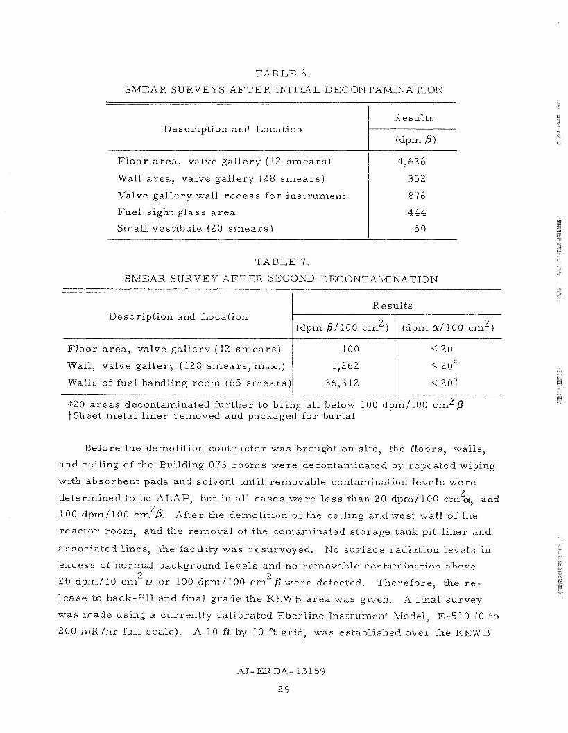
TABLE 6.
SMEAR SURVEYS AFTER INITIAL DECONTAMINATION
Description and Location
Floor a r e a , valve gal lery (12 s m e a r s )
T 7- 1 1 h a i l a rea , valve gallery (28 s m e a r s j
Valve gallery wall r ecess for instrument
Fuel sight glass a r e a
Small vestibule (20 s m e a r s )
TABLE 7.
SMEAR SURVEY AFTER SECOND DECONTAMINATION
Description and Location
Floor a rea , valve gal lery (12 s m e a r s )
Wall, valve gallery ( 12 8 smears , max.)
Walls of fuel handling room (65 s m e a r s )
Results
'1'20 a reas decontaminated fur ther to bring all below 100 dpm/l00 c m 2 P Wheet metal l iner removed and packaged for burial
Before the demolition contractor was brought on site, the floors, walls,
and ceiling of the Building 073 rooms were decontaminated by repeated wiping
with absorbent pads and solvent until removable contamination levels were
determined to be ALAP, but in a l l cases we re l e s s than 20 dpm/ 100 c m
100 dpm/100 cm2 After the demolition of the ceiling and west wall of the
reactor room, and the removal of the contaminated storage tank pit l iner and
associated Lines, the facility was resurveyed, No surface radiation levels in
excess of normal baekgr ound levels and no r ernnva hl e rnnfamin_zt.inr_ ~ h n v e 2
or 100 dpm/100 c m were detected. Therefore, the r e -
lease to back-fill and final grade the K E W B a r e a was given. A final survey
was made using a current ly calibrated Eberline Instrument Model, E-5 10 (0 to
200 mR /hr full sca le) . A 10 f t by 10 ft grid, was established over the KEWB

TABLE 8.
SOIL SAMPLES KEWB AREA
Radioactive liquid t e m p o r a r y holdup tank 1 23.8 1 0.919
Descr ip t ion and Location
Radioactive liquid s t o r age tank 1 23.3 I 1.03
Resu l t s
(pCi1gmBi 1 ( pC i /gm a i
Radioactive gas i l iqu id tanks excavation a r e a 1 21.9 1 0.872
Radioactive gas holdup tank 1 24.6 1 1.05
Radioactive gas l l iqu id tanks excavation a r e a 1 25.0 1 0.950
Base of ex t e r i o r wes t tunnel wall
Northwest c o r n e r of T-073
Northcenter of T-073
Northeas t c o r n e r of T-073
E a s t s ide of T-073
South s ide of T-073
Concre te dus t f r o m r e a c t o r r o o m f loor excavation
F u e l s t o r age l i n e r excavation ( so i l ) / 22.8 1 0.65
Radioactive re tent ion tanks (gas , l iquid) a r e a 0.73 ( 3 s ample s , maximum)
F u e l s t o r age l i n e r excavation ( sands tone)
Ex t e r i o r wes t wal l of tunnel to r e a c t o r r oom
Fac i l i ty no r th cente r p e r i m e t e r ( 2 s amp le s 0.73 max imum)
23.7
22.0
Fac i l i ty w e s t p e r i m e t e r (2 s amp le s max imum)
Fac i l i ty nor thwest c o r n e r - p e r i m e t e r
Fac i l i ty nor theas t quadran t p e r i m e t e r 21.9 ( 2 s amp le s m a x i m u m )
Fac i l i ty e a s t p e r i m e t e r ( 2 s amp le s max imum) 23.0
0.73
0.9 0
2 3.4
21.9
0.90
0.39
Fac i l i ty no r th p e r i m e t e r ad jacen t to tunnel 1 23.1 0.30
NOTE: The 1974 ave rage radioactivi ty l eve l s f o r on - s i t e environmental so i l s amp le s w e r e 0.6 pC i /gm a and 25 pC i /gm

a r e a and the g r i d t r a v e r s e d with the ins t rument 5 in, above the sur face . Back-
ground radiation levels w e r e observed. These levels of radiat ion a r e equiva-
lent to those observed using the s a m e ins t rument and technique to m e a s u r e back-
ground radioactivity l eve l s in an uncontaminated a r e a removed f r o m the K E W B
si te .
The objective of the KEWB Dismantling P l an was to complete the dismantl ing
of the KEWB faci l i t ies so that a l l su r f ace s which r e m a i n we re decont-aminated to
levels which w e r e a s low a s pract icable , but in a l l c a se s , no g r e a t e r than those
of Table 1 of the Dismantl ing Plan. A descr ipt ion of the approach uti l ized for
implementing ALAP pr inciples appea r s in Reference 2.
The radiological su rveys conducted and data p r e sen t ed demonstra te that the
s i te i s total ly f r e e of radioactivity except f o r no rma l background. Resul ts of the
final radiological su rveys w e r e reviewed by the Quality Assurance P r o g r a m
Adminis t ra to r to enable ver i f ica t ion of completion.


Contaminated mater ia l s and equipment accumulated from the KEWB facili-
t ies dismantling operation were sent to the RMDF at AI. The mater ia l s and
equipment were t r ans fe r red to the RMDF in specially constructed boxes o r
wrapped in plast ic sheets and placed on pallets.
After receipt at the RMDF, the radioactive i tems were decontaminated to
levels acceptable for unres t r ic ted use, o r packaged for burial, depending upon
the levels of radioactivity present and the est imated costs for t ime and labor.
3 A total of 3045 ft of radioactive waste from the m W B was shipped to the
Nuclear Engineering Company burial si te at Beatty, Nevada. All waste was
packaged and shipped according to Department of Transportation requirements.


The total co s t s fo r KEWB D&D a r e presented i n Table 9. As i s apparent ,
the m a j o r cos t s w e r e fo r A1 and Rocketdyne labor . The Rocketdyne Division
of Rockwell International provides maintenance support f o r A1 faci l i t ies a t the
field l abo ra to r i e s . Maintenance s e rv i ce s w e r e required mainly fo r d iscon-
nection of u t i l i t ies such a s wate r , e lect r ic i ty , and a i r conditioning.
Nuclear Engineering Corporat ion contracted fo r bur ia l of the radioact ive
was te m a t e r i a l s . Seaboard Construction Company provided the demolit ion and
excavation s e rv i ce s .
TABLE 9.
KEWB FACILITIES D&D COSTS
Total Labor Cos t s
A1
Rocketdyne
Subcontracted Cos t s
Nuclear Engineering Corporat ion $ 7,490
Seaboard Construct ion Company 10,182
Other Cos t s
Mate r i a l s
Miscellaneous
a , G&A
b, F e e
Total D&D Costs $112,934


1. W . K. M a j o r s , "Decon tamina t ion a n d D i s m a n t l i n g K i n e t i c s E x p e r i m e n t W a t e r B o i l e r F a c i l i t y of Bui lding 073, " DWP-704-990-002 , ( J a n u a r y 20, 1975)
2. W. F. H e i n e t o R . L . Wes tby , ERDA-SAN, "Appl ica t ion of ' A s L o w A s P r a c t i c a b l e ' ( A L A P ) P r i n c i p l e s i n the A1 D & D P r o g r a m , 'I A1 L e t t e r 75AT4986 (Augus t 13, 1975)


Atomks Internsttonal Dlvision Rockwell lnteinahonai
ROGRAM TITLE
D E C O N T A M I N A T I O N AND D I S P O S I T I O N OF F A C I L I T I E S
PROGRAM
IOCUMENT TITLE
Dismantling Plan f o r KEIVB F a c i l i t y (Bldgs 073, 123 and 793)
B . F . U r e d a LA1 6 - - LR&D PROGRAM? Y E S u N O I 4 IF YES. E N T L R Z A NO.-
B .F . Ureda 'I'. + I r. r, :L I1 /A- /']
. Breese
. Campbell
. Cockeram . W. Graves . F. Heine (12)
. F. Higgins
. Klosterman
. K. Owens
. Remley
. J. T u t t l e . F. Ureda . Wallace
:. Joh le r
dUMBER REV LTRICHG NO
IOCUMENT TYPE
' a c i l i t i e s Dismantl ing P lan :EY NOUNS
)ismant l i n g Plan IRIGINAL ISSUE DATE
17 O c t o b e r 1974
SECURITY CLASSIFICATION
(CHECK ONE BOX ONLY) I (CHECK ONE BOX ONLY)
CONF DEFENSE
SECRET INFO
?UTHORIZED DATE -LASSlFlER
FORM 734-C REV. 2-74

Dismantling Plan
KEWB Facility, Buildings 073, 793, 123
I. OBJECTIVE
The Kinetics Experiment Water Boiler (KEWB) facility as shown in Fig- ure 1 and Figure 2 was last operated in 1966. The fuel was drained and the system rinsed in 1968. Because of the elapsed time since shutdown, the radiation levels associated with the reactor components are relatively low. Maximum radiation levels at the surface of the core vessel are estimated to be 200 to 300 mR/hr.
The KEWB facility consists of the reactor test building 073, the ex- haust blower building 793, the electrical building, the waste storage build- ing 123, the facility stack and the gaseous and liquid waste holdup tank system.
A. DESCRIPTION OF KEWB FACILITY
1. Reactor Test Building
The reactor test building is an underground concrete structure 15 by 26 by 10 feet high. The outside walls and floor are reinforced concrete 8 inches thick, and the roof is a reinforced concrete slab 1 foot thick. The entire structure is covered with 6 feet of earth for shielding purposes.
The interior of the reactor test building is divided into three rooms: (1) the reactor room that contains the reactor core, graphite reflector, and control rod system; (2) the gas and fuel-handling room, which contains the radiolytic gas recombiner, fuel storage tank and associated plumbing system; (3) the valve gallery that contains the control handles for the valves in the gas and fuel handling system. Concrete shielding walls two feet thick separate the three rooms. A ramp and vestibule entry way lead into the valve gallery. A change and work area, constructed of wood, is at the head of the ramp.
2. Auxiliary Buildings
Ventilation of the reactor building is provided by a 2000-cfm blower that draws air from the building through a bank of absolute filters and discharges it up a disposal stack. Fresh air is admitted into each room by a duct up through the earth covering. Each of these ducts contains a Keystone butterfly valve at its upper end which was closed during operation to seal the building. A similar Keystone valve is located in the exhaust line just ahead of the absolute filter tank. The blower and gas lines are located in Building 793, the exhaust blower building.

V A L V E GALLERY
C H A N G E A R E A BLDG. 793
770462354
Figure 1, Kinetics Experiment Water Boiler Facility

ockwell InternaQonal
F igure 2 - Photograph of Kinetic Exper iment Water Boi ler A r e a and Fac i l i t i e s

The electrical building is located east of the reactor test building. This building contains the electrical panels, air conditioner, and heater. A pit is located in the floor of this building where most of the electrical conduits to the reactor room terminate.
Building 123, a concrete block building, was used for temporary storage of radioactive waste material. Two steel-lined wells 6 feet deep and 2 feet in diameter are located in the concrete floor of this building.
Waste Holdup Tanks
The waste disposal system for the facility consists of three under- ground tanks and a 60 foot exhaust stack with a 2000 cubic feet per minute blower system.
A 300-gallon collection tank, initially at vacuum, was used to collect gas directly from the reactor system.
A storage tank of 1000-gallon capacity buried beneath floor level and adjacent to the test building retained all liquid waste from the facility. This tank is equipped with pump-out connections for removal of the liquid waste when necessary.
The third underground tank, also of 1000-gallon capacity was originally used to retain the reactor cooling water so that it could be checked for activity before release.
8. DISMANTLING AN0 DISPOSITION
The reactor building and associated hardware will be decontaminated and all equipment dismantled, packaged and shipped for burial. The reactor building will be collapsed, the liquid wastes system will be removed and the site will be backfilled and restored to natural grade.
All surfaces which remain following completion of dismantling and all material released for unrestricted use will be decontaminated to levels which are as low as practical, but in all cases to levels below those in Table I.
The exhaust blower building 793, the electrical building, the waste storage building 123, the facility stack and the gaseous and liquid waste holdup tank systems will be decontaminated and removed. The area will be backfilled as necessary.

TABLE I
CONTAMINATION LIMITS FOR DECONTAMINATION AND DISPOSITION OF THE KEWB FACTLITY
Beta-gamma Emitters
Alpha Emitters
Total P
Removable
0.1 mrad at 1 cm with 100 dpm/100 cm 2
7 mg/cm2 absorber
11. SCOPE OF PLAN
The Dismantling Plan delineates the activities necessary to realize the objectives stated above. These activities have been categorized as follotrs:
Planning, monitoring, and control
Radiological survey
Tooling and support equipment procurement
Dismantling and disposal
Documentation.
111. PLANNING, MONITORING, AND CONTROL
A schedule listing the detailed tasks and the sequence of performance has been prepared (see Figure 3). The level of manpower requirements for these activities are also shown in Figure 3.
Specific tasks will be initiated and monitored by the Program Office. The work authorizations, work releases, and progress report issuance will generally follow the format and guide lines set out in the Decontamination and Disposition of Facilities Program Plan. Quality Assurance and Health

and Safety actions will be governed by the Quality Assurance Plan and the Operational Safety Plan, respectively. The schedule and manpower loading charts and the cost records will serve as the overall criteria to measure progress and accumulated costs.
IV. RADIOLOGICAL SURVEY
An initial radiological survey will be made to determine the extent of contamination present in the reactor test building, the exhaust blower build- ing, the waste storage building, and the waste holdup tank system. An as- sessment of the probable levels of contamination are as follows:
A. REACTOR BUILDING
1. Reactor Room
Radiation levels outside the secondary enclosure do not exceed 5 mR/hr except within the exposure ports. From readings taken in the 8 x 8 inch horizontal exposure port, it is estimated that a radiation level of from 200 to 300 mR/hr exists at the surface of the core vessel. The graphite reflector, the control rods, the secondary enclosure, and all parts within the enclosure are assumed to be activated or contaminated from past fuel spills near the core vessel. The control rods and the poison rod will also contain some induced radioactivity.
2. Fuel Handling Room
All gas or fuel piping and equipment in the fuel handling room can be assumed to be contaminated. The floor has low level contamination. The highest radiation level present is about 100 mR/hr at the water trap near the doorway and in one of the pipes near the floor. Radiation levels of 40 mR/hr have been measured at the surface of the recombiner. The radiation levels associated with the main fuel storage tank may be greater than 100 mR/hr when it is removed from its pit in the floor.
3. Valve Gallery
The valve gallery has no appreciable surface contamination except within the fuel and gas handling lines which penetrate the wall from the fuel handling room. Maximum radiation levels of about 2 mR/hr have been measured at the surface of these lines.

ACTIVITY MGM'T
PLANS & PROCEDURES
MI LESTONES
RESTRAINTS
TASK ACTIVITY SCHEDULE SUBMITTED
DISMANTLING PLAN SUBMITTED
SUBCONTRACT AWARD
* ONLY MANPOWER EXPENDITURES ARE SHOWN. OTHER EXPENDITURES FOR MATERIALS, OUTSIDE SERVICES AND ADMINISTRATIVE COSTS ARE ANTICIPATED BUT NOT DEFINED AT THIS TIME.
ilities Program,

B. EXHAUST BLOWER BUILDING
The absolute filters and filter bank housing may be slightly contami- nated. The vent and gas lines connected to the blower may also be slightly contaminated. The blower and stack are not contaminated.
I C. WASTE STORAGE BUILDING I
This building contains a few lead pigs and one source barrel with low level internal contamination.
D. HOLDUP TANKS
The cooling water holdup tank is not contaminated. The gas and wash water holdup tanks may be contaminated. Lines connecting these tanks to the reactor building may also be contaminated.
V . TOOLING AND SUPPORT EQUIPMENT PROCUREMENT
No special tooling requirements are anticipated other than those normally used in handling and packaging radioactive waste for burial. Handling equipment, containers and packaging materials will be procured from the Radioactive Materials Disposal Facility (RMDF) at AI.
VI. DISMANTLING AND DISPOSAL
Detailed procedures will be written to guide the dismantling and dis- posal crews. A brief description of the principal tasks are as follows:
A. PREPARATION FOR DISMANTLING AND DISPOSITION
The health and safety facilities in the reactor building including the change area and the radiological survey station will be renovated as neces- sary to make ready for use. A radiological survey will be conducted of all KEWB facilities. Health and Safety equipment and instrumentation will be made available. Electrical power to facilities will be progressively dis- connected as facilities are removed.
REACTOR BUILDING DECONTAMINATION
The gene ra l decontaminat ion and dismantl ing process w i l l begin i n t h e r e a c t o r room wi th t h e removal of a l l loose equipment and m a t e r i a l , i n s t r u - ment wi r ing and p ip ing , and ins t rumenta t ion cab l e t r ay s . The g r a p h i t e r e f l e c t o r b locks w i l l then be removed, t h e coolan t and gas l i n e s crimped and c u t , po r t i ons of t h e secondary enc losure removed and t h e r e a c t o r core removed. The w a l l s , f l o o r and c e i l i n g w i l l be r a d i o l o g i c a l l y surveyed and cleaned t o t h e l e v e l s requi red .
The f u e l handling room w i l l be dismantled next . The va lve s , l i n e s , vacuum system, d i s t i l l i n g condenser , l i q u i d t r a p s , f u e l mixing chamber, f u e l s t o r a g e t ank , recombiner, a s p i r a t i o n pump, compressed a i r system, gas holdup t ank and t h e wash water system w i l l be removed. Some l i n e s i n t h e concre te f l o o r may be contaminated. These w i l l be excavated. The w a l l s , f l o o r s and c e i l i n g w i l l be r a d i o l o g i c a l l y surveyed and cleaned t o t h e l e v e l s requi red .
The va lve g a l l e r y w i l l then be dismantled. A l l v a lve s , l i n e s manom- e t e r s , s i g h t gauges, t ub ing , p l a s t i c s h e e t i n g , paper , mat t ing , f i r e de tec- t i o n equipment, l i g h t s and e l e c t r i c a l pane ls w i l l be removed. A survey w i l l be conducted and t h e s u r f a c e s cleaned t o t h e l e v e l requi red .
C. ELECTRICAL BUILDING DISMANTLING
Power t o t h e e l e c t r i c a l bu i l d ing w i l l be disconnected. A l l e l e c t r i - c a l l i n e s t o t h e e l e c t r i c a l bu i l d ing w i l l be removed. Telephones, f i r e d e t e c t i o n equipment, h e a t e r equipment, and e l e c t r i c a l pane ls w i l l be re - moved. The bu i l d ing w i l l be unbolted from t h e foundat ion and removed t o sa lvage . The foundat ion w i l l be excavated,
D. WASTE HOLDUP SYSTEM DECONTAlrlIKATION AND DISMANTLING
The waste s t o r age bu i l d ing w i l l be cleaned, power l i n e s removed and t h e bu i l d ing razed . The f i l t e r s , f i l t e r bank housing, power l i n e s , f i r e d e t e c t i o n equipment, gas l i n e s , vacuum pump and e l e c t r i c a l pane ls w i l l be removed from t h e exhaust bu i ld ing . The exhaust s t a c k , blower and d r i v e motor w i l l be removed and t h e bu i l d ing razed.
The t h r e e waste tanks : 300 g a l gas holdup, 1000 g a l cool ing water holdup and t h e 1000 g a l wash water s t o r age and t h e a s soc i a t ed p ip ing w i l l be removed.

E. REACTOR B U I L D I N G REMOVAL
The r e a c t o r bu i ld ing w i l l be co l lapsed and removed. The s i t e w i l l be b a c k f i l l e d and graded t o n a t u r a l contour,
F. FINAL SURVEY
A f i n a l r a d i o l o g i c a l survey of t h e a r e a w i l l be performed p r i o r t o any back f i l l i n g and a f t e r completion of a l l work t o v e r i f y t h a t t h e decon- tamina t ion was accomplished t o t h e l e v e l s a s spec i f i ed .
V T I , DOCUMENTATION
A . PROCEDURES
De ta i l ed procedures w i l l be w r i t t e n t o guide t h e decontamination and d ismant l ing crews. S p e c i f i c r a d i o l o g i c a l and i n d u s t r i a l s a f e t y hazards and t h e means f o r working w i t h and e l im ina t i ng t h e s e hazards w i l l be i d e n t i f i e d . The procedures w i l l show t h a t t h e means w i l l conform t o t h e requirements of t h e Opera t iona l Safe ty P lan and compliance w i th t he se requirements w i l l be monitored by Qua l i t y Assurance and Health and Safe ty . Deta i led procedures w i l l be r e l e a sed and c o n t r o l l e d by t h e A 1 Engineering Data Release System.
B. REPORTING
Progress on t h e KEWB D&D a c t i v i t i e s w i l l be r epo r t ed t o AEC San Franc isco i n t h e Decontamination and D i spos i t i on of F a c i l i t i e s Program monthly r e p o r t .
6 . RECORD INFORMATION
The r e s u l t s of r a d i o l o g i c a l surveys of t h e a r e a s , m a t e r i a l s , and equip- ment w i l l be recorded and c e r t i f i e d . A complete accounting of a l l rad io- a c t i v i t y disposed of by RMDF w i l l be maintained. Photographic coverage of t h e more s i g n i f i c a n t phases of d i smant l ing w i l l be ob ta ined both i n s t i l l photos and i n motion p i c t u r e s ,
D. FINAL REPORT
The f i n a l r e p o r t w i l l d e sc r i be t h e d i smant l ing and decontaminat ion a c t i v i t i e s . Problem a r e a s and t h e subsequent s o l u t i o n s w i l l be h igh l i gh t ed , Shipping r eco rds showing q u a n t i t i e s of m a t e r i a l and t h e l e v e l of rad io- a c t i v i t y w i l l be included. The r e p o r t w i l l con t a in the QA and HGS s a f e t y r e co rds c e r t i f y i n g t h e r epo r t ed s t a t u s of t h e KEWB a r e a upon completion.
