att-tp-76401-001 internet services cabinet supported cable
TRANSCRIPT

ATT Practice ATT-TP-76401-001Issue 2, 09/01/2007
©2003 SBC Management Services, Inc. All Rights Reserved. 1
ATT-TP-76401-001 Internet Services Cabinet Supported
Cable Rack Requirements
This practice provides the guidelines and requirements for engineering and installing cable rack arrangements in AT&T IS equipment environments
Audience: All AT&T IS employees and contractors Effective Date: September 1, 2007 Issue Date: September 1, 2007 Expires On: NA Related Documents: SBC-002-316-053, ATT-TP-76305 and ATT-TP-76409. Cancelled Documents: Issuing Department: Network Planning and Engineering – Common Systems Business Unit: AT&T Services, Inc. Points of Contact: Author(s): Larry Wong, 925 823-4544 SBCUID: lw6932

ATT Practice ATT-TP-76401-001Issue 2, 09/01/2007
©2003 SBC Management Services, Inc. All Rights Reserved. 2
Table of Contents INTRODUCTION……………………………………………………………………………… 4 1. RESERVED FOR FUTURE……………………………………………………........ 5 2. GENERAL…………………………………………………………………………….. 5
2.1 Description and Sizes………………………………………………………... 5
2.2 Safe Loads……………………………………………………………………. 5
2.2.1 Permissible Cable Pileups………………………………………….. 5
2.3 Planning……………………………………………………………………….. 6
2.4 General Engineering Requirements………………………………………... 6
2.4.1 Rack Support span…………………………………………………… 6 2.4.2 Rack Sizing…………………………………………………………… 7 2.4.3 Cable Routing Diversity……………………………………………… 7 2.4.4 Entrance Cable Racks………………………………………………. 7 2.4.5 Lineup Cable Racks…………………………………………………. 8 2.4.6 Cross Aisle Cable Racks……………………………………………. 9 2.4.7 Via Cable Racks……………………………………………………… 9
2.5 Cable Pileup Monitoring…………………………………………………….. 9
2.6 Cable Rack Restrictive Markings……………………………………………. 9
2.7 At Customer Premises……………………………………………………….. 10
3. ASSEMBLY…………………………………………………………………………. 10
3.1 Junctions……………………………………………………………………… 10 3.1.1 Horizontal to Vertical Transitions………………………………….. 11 3.1.2 In-Line Transitions…………………………………………………… 11
3.2 Terminations…………………………………………………………………. 11
4. SUPPORT……………………………………………………………………………. 11 4.1 Cable Rack Support …………………………………………………………. 11
4.1.1. Direct Attachment ……………………………………………………. 11 4.1.2 Studded up Arrangement …………………………………………… 12 4.1.3 Two and four post Frameworks ……………………………………. 12 4.1.4 Support Spacing Requirements ……………………………………. 12
ATT Practice ATT-TP-76401-001Issue 2, 09/01/2007
©2003 SBC Management Services, Inc. All Rights Reserved. 3
4.2 Stacked Racks………………………………………………………………... 13
4.3 Racks On Walls and Columns…………………………………………….. 13 4.3.1 Vertical Racks……………………………………………………….. 13 4.3.2 Horizontal Racks……………………………………………………. 13
4.4 Cable Racks On Floors……………..……………………………………… 14 5. MISCELLANEOUS CABLE SUPPORTS………………………………………... 14 6. CABLE RACK PANS AND CABLE RETAINING BRACKETS………………… 14 6.1 Cable Rack Used For Unsecured Cable……………………………………………. 14 6.2 Cable Rack Horns…………………………………………………………………….. 14 6.3 Separating Parallel Runs Of Cable…………………………………………………. 15 6.4 Cable Rack Pans……………………………………………………………………… 15 7. LIGHT FIXTURE SUPPORT………………………………………………………. 15 7.1 Supporting Light Fixtures Along Aisles……………………………………………… 15 8.1 FIGURES AND SKETCHES………………………………………………………. 16

ATT Practice ATT-TP-76401-001Issue 2, 09/01/2007
©2003 SBC Management Services, Inc. All Rights Reserved. 4
INTRODUCTION
This practice shall be followed when providing cabinet top supported cable racks for AT&T Internet Services facilities. These methods for support of cable racks are applied when ceiling suspended auxiliary framing is not available for supporting of cable racks. This practice should be used in conjunction with TP76305 Cable Installation, Removal and Mining, ATT-002-316-053 Fiber Protection System M&P and TP76409 Common Systems Cable Rack Requirements. The following is a list of terms and their meanings as used in this document:
Term Meaning
Access floor Cabinet
A raised floor system elevated over the building floor providing space under the floor panels for air plenum use or cable runs. Equipment frameworks/cabinets are mounted on top of elevated floor system. A four post framework designed for housing electronic equipment that may be equipped with or without doors, side panels, top panel or base panel.
Cable Hole
An opening in a wall, partition, or floor for passage of cable and wire.
Cable Rack
Equipment Framework Four Post Framework
The supporting structure for dc power and copper communications cable. A steel framework for housing electronic equipment in a rack mount arrangement, usually a two post design used in the context of this document. Steel framework for housing electronic equipment incorporating four uprights in one assembly such as a cabinet. For purposes of this document, two-post equipment frameworks configured back-to-back and joined by top and bottom crossmembers between the two frameworks may also be termed four post framework.
Global Seismic Framework Power Cable Rack Stacked Racks
Equipment framework designed and manufactured by Telect Hendry with uprights exceeding 5 inch depth creating performance characteristics similar to four post framework. Cable rack that is dedicated (restricted) to the routing and support of office and equipment of dc power cables. Cable racks that are run parallel to each other at different vertical heights intended to be one over the other. Stacked cable racks are typically provided to dedicate racks for specific cable applications.
Switchboard / Misc. Cable Rack
Cable rack that is used for routing and support of network switching, transmission and video cables in general. Switchboard cable racks may contain certain types of equipment dc power distribution cables.

ATT Practice ATT-TP-76401-001Issue 2, 09/01/2007
©2003 SBC Management Services, Inc. All Rights Reserved. 5
1. RESERVED FOR FUTURE
2. GENERAL
2.1 Description and Sizes Cable racks used in ATT IS facilities shall be of the steel ladder type construction shown in Fig. 1. Cable racks shall consist of 2 x 3/8 inch solid rectangular side rails called “stringers” between which are welded on 9-inch centers 1 x 1/2 inch cross members called “straps”. The first and every other strap of cable racks wider than 24 inches shall be reinforced with a 1 inch by 1/4-inch steel bar. Fig. 1 also indicates the standard widths of cable rack that shall be used in ATT IS facilities. Commercially available cable racks having widths different than those shown are acceptable for use when they are appropriate for the cabling needs of a particular equipment or office arrangement. NOTE: Cable racks with side cable horns welded to stringers shall not be provided for new or
growth of existing office cable rack arrangements. 2.2 Safe Loads 2.2.1 Permissible Cable Pileups The permissible pileups of cabling on horizontal cable racks supported by cabinets are provided in Table A. The purpose of cable pileup restrictions are to ensure the weight of cables does not exceed load carrying capacity of cabinet and/or equipment frameworks supporting the cable rack. Generally, cable rack weight shall not place more than 500 pound top load on any one cabinet. The 5-foot and 6-foot spacing of supports are standard spans provided for cable racks. Providing supports at smaller span distance of 4-foot can provide greater cable load capacity where greater cable pile height is required.
Table A Permissible Cable Pileup On Cabinet Supported Horizontal Racks
Secured Power Cable
(3 Levels of Rack) Supports On
Rack Width 4’ Centers 5’ Centers 6’ Centers5” to 1’-6” 3” 3” 3”
Unsecured Switchboard Cable (3 Levels of Rack)
Supports On Rack Width 4’ Centers 5’ Centers 6’ Centers5” to 2’-0” 6” 5” 5”
Secured Power Cable (2 Levels of Rack)
Supports On Rack Width 4’ Centers 5’ Centers 6’ Centers5” to 1’-6” 3” 3” 3”
Unsecured Switchboard Cable (2 Levels of Rack)
Supports On Rack Width 4’ Centers 5’ Centers 6’ Centers5” to 2’-0” 8” 6” 6”

ATT Practice ATT-TP-76401-001Issue 2, 09/01/2007
©2003 SBC Management Services, Inc. All Rights Reserved. 6
2.3. Planning The objective of cable rack engineering is to assure equipment and office cable rack layouts are configured in a way that cable pileup is distributed across an equipment area so that unnecessary concentrations of cable (congestion) on individual racks are avoided. Secondly, cable rack engineering assures a reasonable capacity for additional equipment cabling is provided for subsequent equipment growth, thus minimizing the need to engineer and install additional racking as equipment is installed. This is accomplished by engineering cable rack arrangements for foreseeable needs rather than just needs of a particular job. Equipment cable racking should only be furnished and installed for equipment configurations engineering knows or is reasonably certain will be installed in the near future, and to comply with the 75% cable capacity requirement discussed later in this document. To communicate a developed overall cabling scheme of an equipment area to subsequent cable rack engineers, the overall plan for an equipment area should be depicted on Cable Rack Plan office records. Using traditional office record keeping standards, future cable rack paths are depicted in solid or dashed thin line work as opposed to existing cable rack paths which are depicted using heavy solid line work. The practice of continuously documenting cable racking schemes in this manner should enable harmonious equipment and cable rack growth and simplified subsequent cable rack engineering effort. 2.4. General Engineering Requirements The following guidelines apply to cable rack engineering in general:
A. Power cable racks shall not exceed 1’-6” in width.
B. Cable racks shall not be located close to building conditions or equipment that may subject installed cabling to damage or detrimental conditions.
C. Except as noted below, cables leaving a cable rack and entering equipment frames/cabinets shall not be unsupported for a distance greater than 3-feet (measured along the arc of the shortest cable).
D. Unless otherwise directed by equipment documentation, lineup cable racks shall be placed at the front of equipment frames to complement the front mounted rear cabled characteristics of equipment units.
E. A clearance of 5-inches should be provided between the side or end of a cable rack and a building column or surface.
F. An installer’s hand/forearm clearance of 4 inches should be provided between the ultimate cable pileup of a cable rack and any obstruction when possible.
G. A minimum of 1’-6” of working space should be provided on at least one side of a cable rack for installation access when possible and practicable.
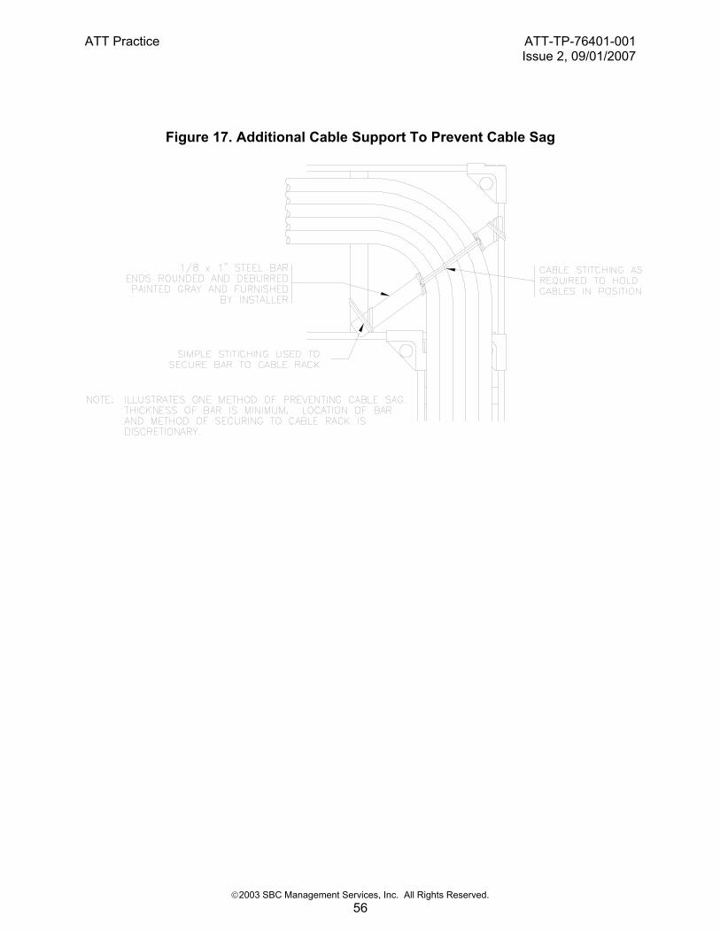
H. Fig. 17 or its functional equivalent shall be provided at cable rack turns where the distance between cable supports does/may not prevent cable sag.
2.4.1 Rack Support Span For the purpose of maintaining cable rack integrity, distance between rack under supports shall never be greater than six feet. In a cabinet/framework supported cable rack environment, there may be spans greater than six feet from one cabinet top support to another cabinet top support when the cable rack runs are away from cabinet lineup areas. This would occur in cross aisle runs, entrance cable racks or via cable racks where the racks must cross over wide aisles or cables are routed to equipment areas located in other parts of the building. Supplemental

ATT Practice ATT-TP-76401-001Issue 2, 09/01/2007
©2003 SBC Management Services, Inc. All Rights Reserved. 7
support must be provided so cable rack span never exceeds six feet. The planning of cable routes should limit number of cable rack runs located away from equipment lineups as supplemental rack support would need to be provided. Supplemental support is provided by ceiling hangers, wall braced framing or floor supports. Floor supports may be provided by floor stanchions or pipe stands where pipe stands will be permitted. Generally, pipe stands cannot be used in high seismic risk sites (Zones 3,4). All floor supports shall be secured to building floor or to access floors if access floor is designed for dead equipment loads. Dead loads are those weights and fixed equipment incorporated into the floor where the floor must be capable of resisting lateral and vertical loads of floor and equipment mass. Ceiling hangers or wall braced support are appropriate where available.
2.4.2. Rack Sizing Cable rack layouts shall be engineered using cable rack widths that are appropriate for the cable rack’s purpose and installed location. A cable rack’s purpose is to accommodate equipment cabling over an extended period of time (general purpose racks), or to accommodate a specific amount of cabling to a specific equipment type or location (special purpose racks). Special purpose racks are not intended for general equipment cabling and shall be sized to the narrowest width possible to minimize the consumption of overhead cable rack space in general. The following is how the different standard cable rack widths should be applied for general purpose equipment cable rack layouts:
≤1’-0” Small or isolated equipment areas having limited long term cable capacity requirements.
1’-3” Cable racking in general where aisle space and installer access is limited.
1’-6” Cross aisle, via, and DC power cable racks in general; vertical racks for cables passing through building floors; lineup racks for conventional office distributing frames (minimum width) and manual DSX equipment; lineup racks for equipment areas employing the use of wide equipment aisle ways (nominally 4’-0” front and 3’-0” rear).
2’-0” As necessary to suit specific equipment or office conditions. These wide racks are usually appropriate where cable pileup space is severely restricted by HVAC ducts and other obstructions.
2.4.3. Cable Route Diversity Engineering cable route diversity into an office cable distribution system (cabling scheme or cable rack layout) is a vital component of effectively managing cable lengths, cable pileup, congestion, the usable life of an installed cable rack arrangement. Cable route diversity may also be necessary to assure service reliability and as such cable distribution systems shall provide capacity for additional volume of cables and alternative cable paths to accomplish diverse routing. Cable route diversity is a matter of providing multiple cable rack paths directly above equipment (cross aisle racks) and between equipment areas (via racks), and engineering cable lengths and routes using more than one cable rack path when appropriate (service protection or pileup avoidance).
To accomplish the above, more than enough cable capacity shall be engineered into network equipment environments initially by the use of multiple cable rack paths. The more cable paths there are, the easier it is to spread cable across an area, the less cable pileup there will be in general and at any one cable rack location, and the easier it will be to access and remove cable no longer in service.
ATT Practice ATT-TP-76401-001Issue 2, 09/01/2007
©2003 SBC Management Services, Inc. All Rights Reserved. 8
2.4.4. Entrance Cable Racks Entrance cable racks are used to route outside plant (OSP) cable from the cable entrance facility (CEF) to terminating equipment such as office distribution frames. For SBC IS applications OSP cables may include outside fiber optic, antenna coax, satellite coax as well as twisted pair. Unless otherwise documented, OSP cable shall not be placed on cable racks with other office cabling. It is expected that OSP cable will be installed for the life of an office whereas other network cables are subject to cable removal and mining activity as equipment is relocated and replaced during the life of an office. Physically separating OSP cable from other network cabling minimizes the possibility of damage to OSP cables during the installation removal management of other equipment cabling. Cable racks for OSP cables shall never be run from the exterior of the building into the interior of the building as a continuous run. The cable rack must not provide a conductive path from outside of the building. Cable racks inside of the building shall terminate at the interior side of the cable entrance facility with no metallic connection to exterior cable rack if used. Entrance cable rack for equipment frames installed along cable entrance facility building walls shall be installed at the rear of the equipment lineup. Entrance racks to equipment frames located interior to an equipment area shall be located at the highest level practical in an office to minimize any up-and-over cable rack arrangements and people activity. 2.4.5. Lineup Cable Racks Lineup cable racks are used to route cables between equipment frames within the same equipment lineup. Lineup racks shall be located above equipment frames/cabinets (over-frame). Some equipment requires more than one type of lineup rack because different types of cable are used to interconnect the equipment to other network elements. Lineup racks used for different cable types should be arranged in one above the other or stacked (likewise for any associated cross aisle racks). Stacked cable rack arrangements should be engineered so the greater or heaviest amount of cabling is installed at the lowest cable rack level to minimize cable installation and removal effort. For most equipment areas the lowest level of cable rack is used for copper based cables (twisted pair, coax and shielded). The upper level(s) of rack would be used for fiber optic and special purpose cable racks. Primary DC power cables, if applicable, should be placed in the upper most level cable rack. For the cabinet supported cable rack environment, the lineup cable racks will be stacked vertically with standoff support arrangement. The maximum number of cable racks that are permitted to be configured in the stacked arrangement is three at no more than 12 inches between vertical levels. Lineup cable rack positioning over equipment framework should be engineered so cable rack stringer’s rear edge is positioned so cables coming off cable rack enter equipment framework with minimal horizontal run and directly access cabinet cable support brackets. Cable racks shall also be positioned where cables coming off cable rack shall have appropriate bend radius for the type of cables being installed. Use of a waterfall or drop-out devices may be necessary to maintain radius depending on cable being used. Refer to other AT&T documents that address bend radius requirements or as a minimum maintain 10 times the diameter radius. Cables entering at the front of framework shall otherwise have stringer of cable rack aligned to where they enter framework. Cables should come off cable rack outside of the stringers rather than from between stringers. Cables shall not go unsupported for more than 3 feet measured from cable rack stringer to first point of cable securing at the framework. With cabinets or framework depths of 36 inches or more, the front-to-back horizontal location of cable racks across the top could range over a large distance, especially for narrower cable rack widths.

ATT Practice ATT-TP-76401-001Issue 2, 09/01/2007
©2003 SBC Management Services, Inc. All Rights Reserved. 9
Cable rack width and horizontal placement of the rack should be chosen for cable capacity required, good access of rack and cable management needs. There is an increasing use of fiber optic cable to interconnect equipment. Accordingly, for some equipment types or areas the greater or heaviest amount of cabling to be accommodated may be that of fiber optic cables with copper cables being used only for miscellaneous interconnections such as alarms, secondary power distribution, intercom equipment, etc. Under this scenario fiber optic cable racks or raceways could be engineered as the lowest level of cable rack for the fiber equipment area, and transitional cable racks engineered for changing the copper cable to a higher level as it enters the area. Equipment requiring fiber jumpers between equipment and cabinets may be best served by fiber guide systems. Refer to ATT-002-316-053, Fiber Protection System M&P for methods and procedures on implementing ADC FiberGuide. 2.4.6. Cross Aisle Cable Racks Cross aisle racks are short lengths of cable rack placed directly above and at a right angle to equipment lineup racks and are used to provide as direct a cable route as possible between equipment frames in different equipment lineups. As shown in Fig. 2, cross aisle racks intersect lineup racks and are not continuous runs of cable rack crossing lineup racks. The cross aisle cable rack running between lineup cable racks shall be one piece and never have splices to complete length of run. Cross aisle cable racks shall be located along equipment lineups with approximately 5-feet of space between racks. This spreads cable pileup along the length of equipment lineups avoiding extreme cable pileups on lineup racks. The above cross aisle cabling scheme shall be applied to all levels of lineup cable rack engineered into an equipment area except where it is known the inter-lineup cabling of equipment by the upper level racks (lesser overall amount of cabling) will be minimal. Under these circumstances the space between cross aisle cable racks may be increased, or narrow racks can be used to minimize cable rack congestion in the overhead environment. 2.4.7. Via Cable Racks Via racks are used to route relatively large amounts of cabling from one equipment location to another without contributing to the cable pileup of an intermediate equipment area’s cable distribution system or scheme. Via racks are usually located at a higher level than equipment lineup and cross aisle cable racking. Power cable racks are one example of a via cable rack. 2.5. Cable Pileup Monitoring Cable pileup in office cable racks needs to be continuously monitored so it is known in advance when office cable racks are reaching their ultimate cable capacity, and additional cable racks and/or cable mining is required. An alternate cable management plan (additional cable rack or cable removal effort) should be developed once installed cable racks reach 80% of their ultimate cable capacity (approximately 4-3/4 vertical inches). 2.6. Cable Rack Restrictive Markings All special purpose cable racks shall be uniquely identified to indicate the type(s) of cable they are restricted to. The restrictive information shall be in the form of labels or stampings conspicuously spaced no more than 10-feet apart on both cable rack stringers. In the case of cable racks used for the routing of fiber optic cables, it is acceptable for the cable racks to have a yellow painted finish, or to use self adhesive labels having black characters printed on a yellow background to distinguish them from other office cable racks.

ATT Practice ATT-TP-76401-001Issue 2, 09/01/2007
©2003 SBC Management Services, Inc. All Rights Reserved. 10
2.7. At Customer Premises The engineering of equipment and cable rack for a customer’s premises application will be done under one of two general scenarios. The first being where the equipment environment is managed by the customer and AT&T IS would be one of several service providers having equipment in the environment. The second scenario is where the equipment environment is essentially established solely for the purpose of accommodating AT&T IS’s equipment. In this scenario equipment engineering, and subsequently the equipment environment, is managed by AT&T IS. The engineering and installation of cable racks at customer premises locations shall be in accordance with the customer’s guidelines and requirements for those equipment environments managed by the customer. In the absence of customer documented guidelines, the subject of cable rack engineering shall be negotiated with the customer and documented using this section as reference when possible. The negotiated customer requirements, with regard to cable rack ownership, seismic protection, cable rack construction, support methods, and other matters that directly impact the process of cable rack engineering and installation of current and future jobs, shall be documented on AT&T IS office record(s) created for the equipment area.
3. ASSEMBLY
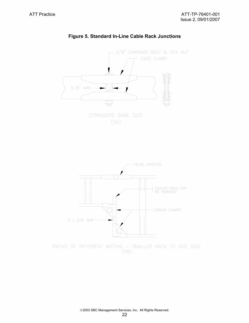
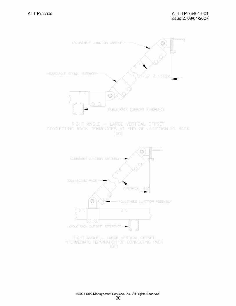
Cable rack fabrications should be assembled using the clamping details shown in this practice. Adjustable in-line cable rack clamping hardware is preferred for assembling vertical changes in cable runs (see Fig. 6G and 7A for example). However, it is acceptable to use non-adjustable clamps if desired. Where cable rack straps interfere with the proper placing of the clamping details, the cable rack shall be cut back to such a point that the straps will not interfere with the clamping details. Corner clamps may be assembled in positions opposite those shown where necessary to avoid interference with cable rack stringers and straps. Except as indicated in 3.1.1 and Fig. 6F, vertical changes in cable route direction shall be provided for via gradual inclines (±45 degrees) or preformed cable rack turns to avoid sharp bends in cable. Abrupt 90 degree vertical turns in cable rack runs should be used only when absolutely necessary. 3.1. Junctions In general, the longest lengths and the fewest parts practicable shall be used in the assembly of cable rack arrangements. The joining of sections of cable rack for the usual conditions encountered in equipment environments are shown in Fig. 5A through 8B. The method of in-line junctioning (splicing) two sections of cable rack together is shown in Fig. 5A and 5H. No more than one in-line junction shall be used between any two points of support for horizontal runs of cable rack. An in-line junction shall not be used beyond the last point of support of cantilevered racks. Cross aisle racks shall be installed at same level as lineup racks as shown in Fig. 6A. Cross aisle cable racks may be installed at higher level than lineup racks as shown in Fig. 6B when additional vertical clearance under cable rack is required in aisles. All cross aisle cable racks for a given equipment area shall be engineered and installed in a common manner. The Fig. 6B “J” bolt fastenings shall be installed at all intersections of cross aisle to lineup cable rack. Fig. 6CA or Fig. 6CB corner brackets shall be used at cable rack junctions where the radii of the cables is so large that additional cable support is required, or where cables need to be spread out to avoid excessive pile-up.

ATT Practice ATT-TP-76401-001Issue 2, 09/01/2007
©2003 SBC Management Services, Inc. All Rights Reserved. 11
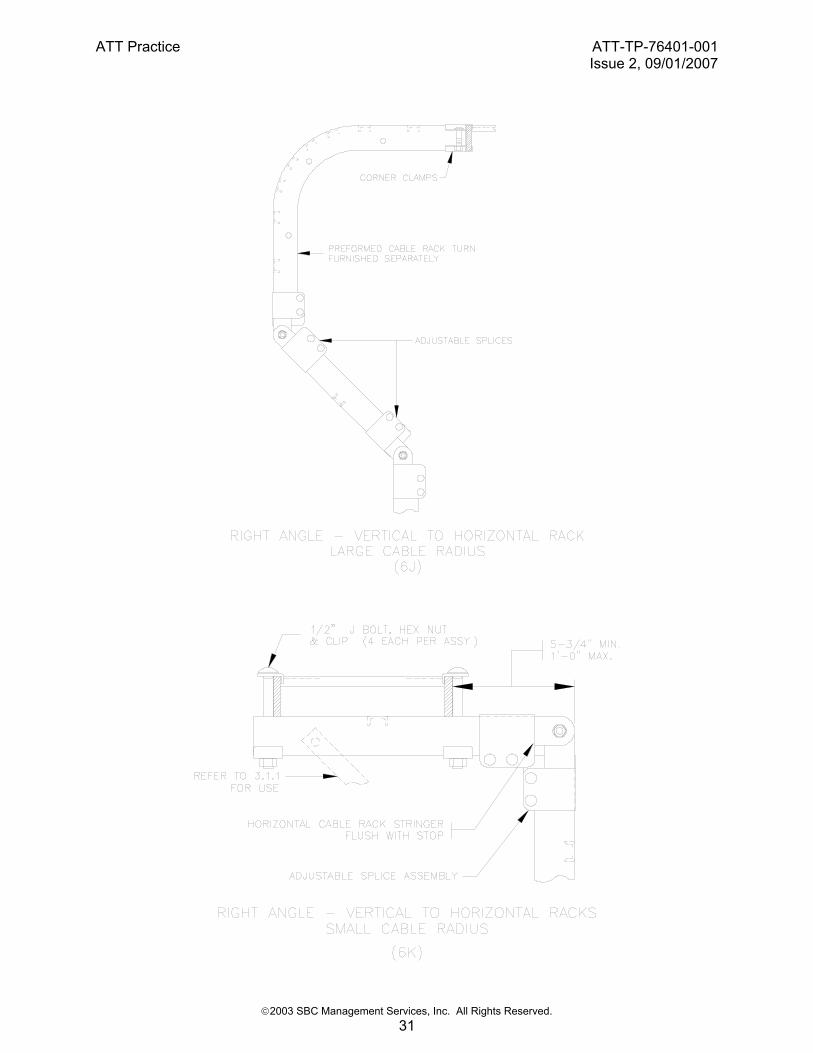
3.1.1. Horizontal To Vertical Transitions
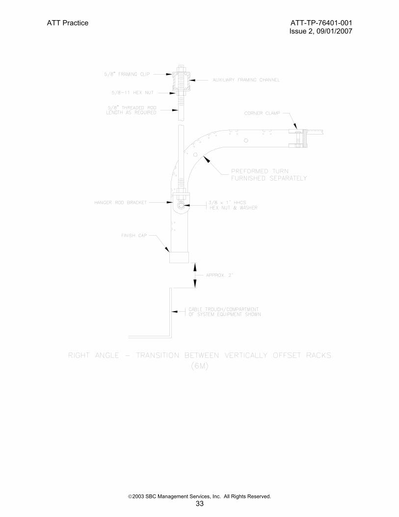
Fig. 6J or 6K shall be used when it is necessary to transfer large cables (≥3/4” dia.) from the horizontal to vertical plane above cable holes when the horizontal rack is at a right angle and in close proximity to the location of the cable hole. Fig. 6L can be used in place of Fig. 6J and 6K for small diameter cable and when dictated by existing cable rack configurations. Use Fig. 6M whenever possible to transition cables vertically between cable racks that are more than 3 cable feet apart and are of a different construction, or are part of different ground planes. The Fig. 6M support rods may be omitted when the preformed cable rack turn is supported by direct attachment to auxiliary framing as shown in Fig. 10A or Fig. 10C. Fig. 6K can be used in place of Fig. 6M for this type of cable transfer when the upper and lower cable racks are horizontally less than 1’-4” apart provided the vertical section of cable rack is 3 feet or less in length and:
• Is independently supported similar to Fig. 6M or
• Is equipped with ±45° 5/8-11 threaded rod or flat bar bracing on both sides of the cable rack and
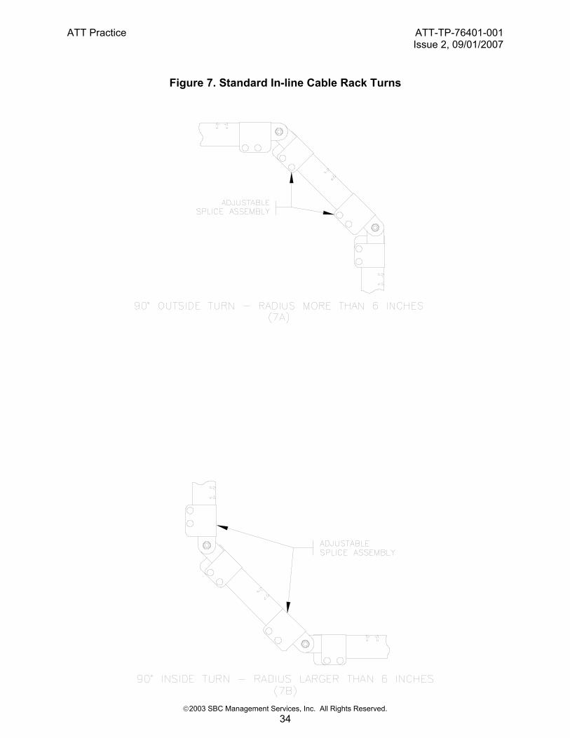
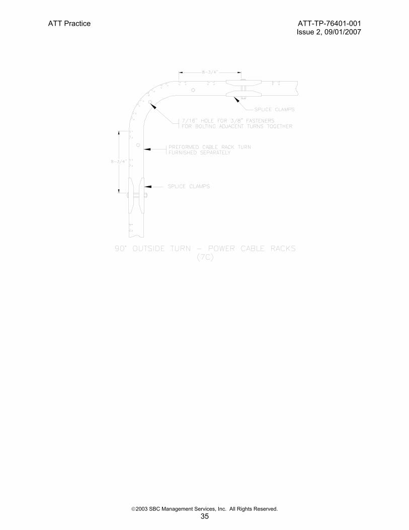
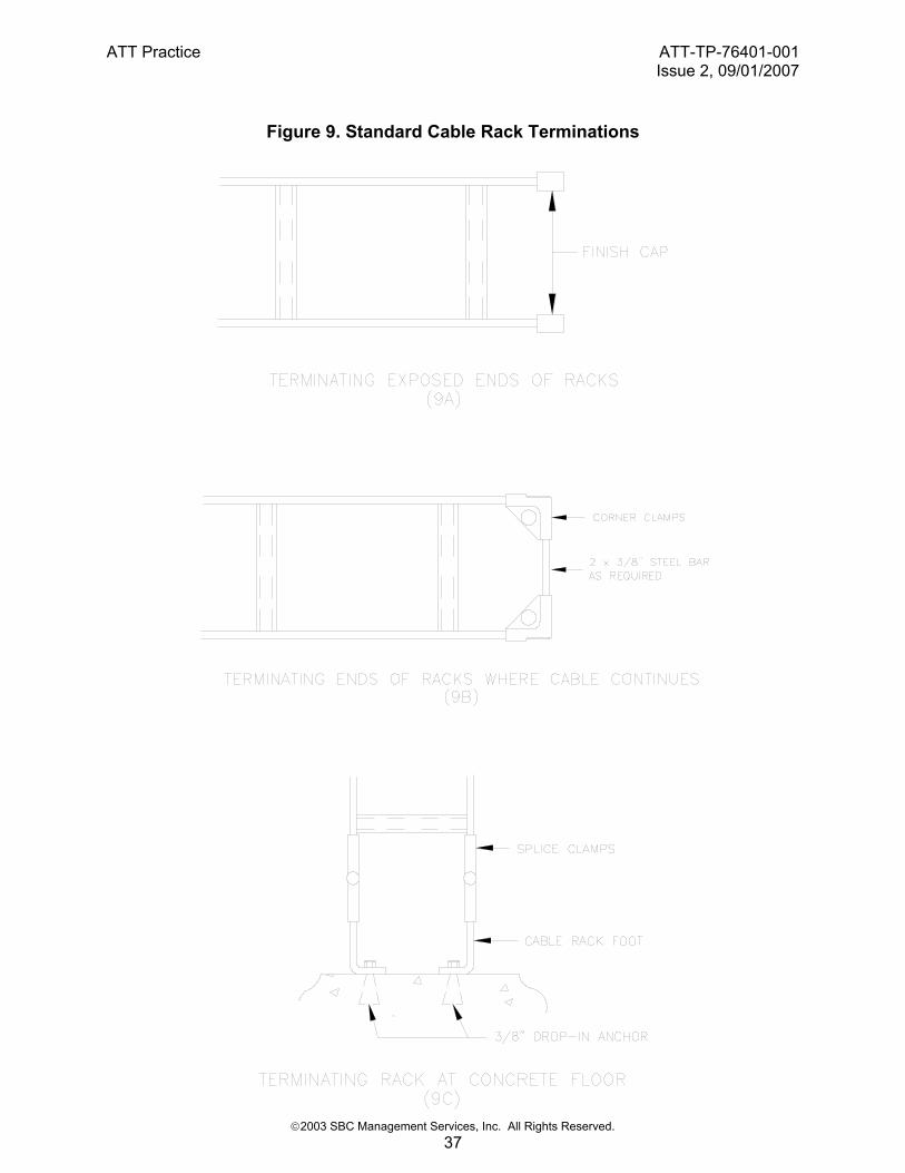
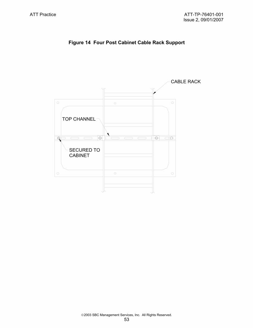
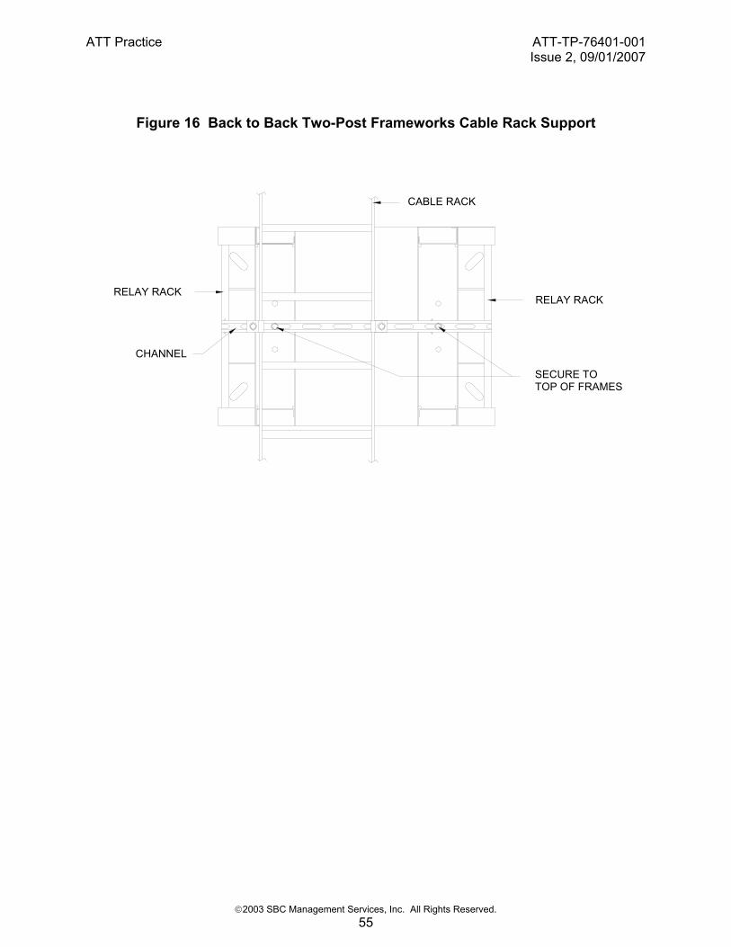
• The ±45° bracing is bolted to the horizontal portion of the cable rack transition. 3.1.2. In-line Transitions In-line transitions of cable from the horizontal to vertical plane should be via Fig. 7A to 7C large cable radius fabrications whenever possible. Transitions of switchboard cable racks should be per Fig. 7A and 7B, however, the use of Fig. 7C is acceptable. Transitions of power cable racks shall be per Fig. 7B and 7C. The intermediate cross straps of the short section of rack shown in Fig. 7B shall be removed from power cable racks if the uninterrupted cable rise exceeds two floors. This is to minimize the possibility of cable insulation damage due to the weight of sagging power cables. Clamps used to hold short sections of cable rack in place as shown in Fig. 7A, 7B and 8B to obtain a cable rack offset, or large cable turning radius shall not be subjected to any load other than the cabling at the turn or offset. 3.2. Terminations The ends of cable rack shall be terminated as shown in Fig. 9A through 9F. Fig. 9A caps shall also be used on the ends of all cable rack attachment bars (refer to Fig. 6F as an example). Terminating vertical cable rack at cable holes with angle type sheathing may be done as shown in Fig. 9F. Fig. 9B closing bars shall be used at non-attached offsets, junctions, and cable rack ends where cables continue to equipment or another cable rack. The cable rack feet shown in Fig. 9C may be turned outward at the floor if space permits and the end of the cable rack is enclosed or a trip hazard is otherwise avoided. 4. SUPPORT 4.1 Cable Rack Support 4.1.1 Direct Attachment Preferred method of supporting cable racks shall be direct attachment to cabinet top mounted channels as shown in Fig. 12. The channels shall be secured to the cabinet with a minimum of two ½” capscrews throughbolted to the top plate of the cabinet as shown in Fig. 14. For applications where greater vertical clearance in aisles will be necessary, an optional bracket for increasing cable rack height is shown in Figs 12A and 12B. The bracket will provide additional 5-3/8 inches height beyond the channel height of 1-5/8 inches. The channels will be placed perpendicular to the direction of the cable rack run and shall be positioned in front to back
ATT Practice ATT-TP-76401-001Issue 2, 09/01/2007
©2003 SBC Management Services, Inc. All Rights Reserved. 12
direction of the cabinets. Cabinets that will be used for supporting cable rack must be of consistent and appropriate height, usually 7’-0”, for the length of the cable rack run. Cabinets must be secured to building floor or to an access floor system that has been designed for securing cabinets directly to floor panel. Cable racks shall not be supported by their cross straps. Cable rack stringers shall rest on cabinet top channels and stringers secured by hold down brackets to the channel. Additional flexibility on locating cable rack supports can be provided by parallel runs of Unistrut channel along front and rear edges of cabinet top as shown in Figure 12D. These two parallel channels run inline with the lineup allows cable rack supports to be located anywhere along channel run rather than be restricted to fixed hole locations on top of the cabinets. The parallel channels adds 1-5/8 inch height to the cable rack support assembly for greater aisle clearance if necessary. 4.1.2 Studded-Up Arrangement Threaded rod studded up framing arrangements to support cable rack run from cabinet top are not recommended due to limited load capacity of threaded rods. In high seismic risk locations, studded up arrangements are not allowed. In low seismic risk locations, if studded up cable racks are utilized, the maximum height of the arrangement is not to exceed 6 inches, measured from top of cabinet or cabinet-top mounted channel, if used, to lowest point of cable rack, as shown in Fig. 12C. Any length of exposed threaded rod shall be enclosed by 1 inch schedule 40 steel pipe sleeves to provide greater vertical and lateral load capability as well as protection of cables from sharp threads. A washer shall be installed at each end of the pipe sleeve as shown in Figure 10C. Studded up arrangement may only be used to support auxiliary framing or Unistrut channels installed to support lowest cable rack level above the cabinet or frame. 4.1.3 Two and Four Post Frameworks Lineups of two-post frameworks may only be used for support of overhead cable racks when configured in four-post arrangement as shown in Fig. 16. The four-post arrangement is a back to back configuration of frameworks with structural attachment between the frameworks. The assembly of frameworks shall have depth of 24 inches or greater. Two post framework designs of 24-inch or greater depth similar to Telect Hendry Global Seismic framework as shown in Fig. 15 may be used for support of cable racks. Cable racks are supported with length of top channel similar to cabinets. 4.1.4 Support Spacing Requirements Horizontal cable racks should be supported on approximately 5 foot centers and in no case shall the spacing of supports exceed 6-feet. Cable rack support provided at less than 5-foot centers may be considered for heavier cable loads. Cable rack assembly hardware shall not be relied upon to carry any appreciable load. Except as noted in this and the following paragraph a cable rack support shall be provided within 2’-6” of a free-end of cable rack. A support is required for each cable rack shown in Fig. 5B to 5G, 6D, 6E and 8B. A. The support for Fig. 6M and 7C applications shall be placed on the horizontal section of
cable rack.
B. The support for Fig. 8A applications may be provided for either run of cable rack.

ATT Practice ATT-TP-76401-001Issue 2, 09/01/2007
©2003 SBC Management Services, Inc. All Rights Reserved. 13
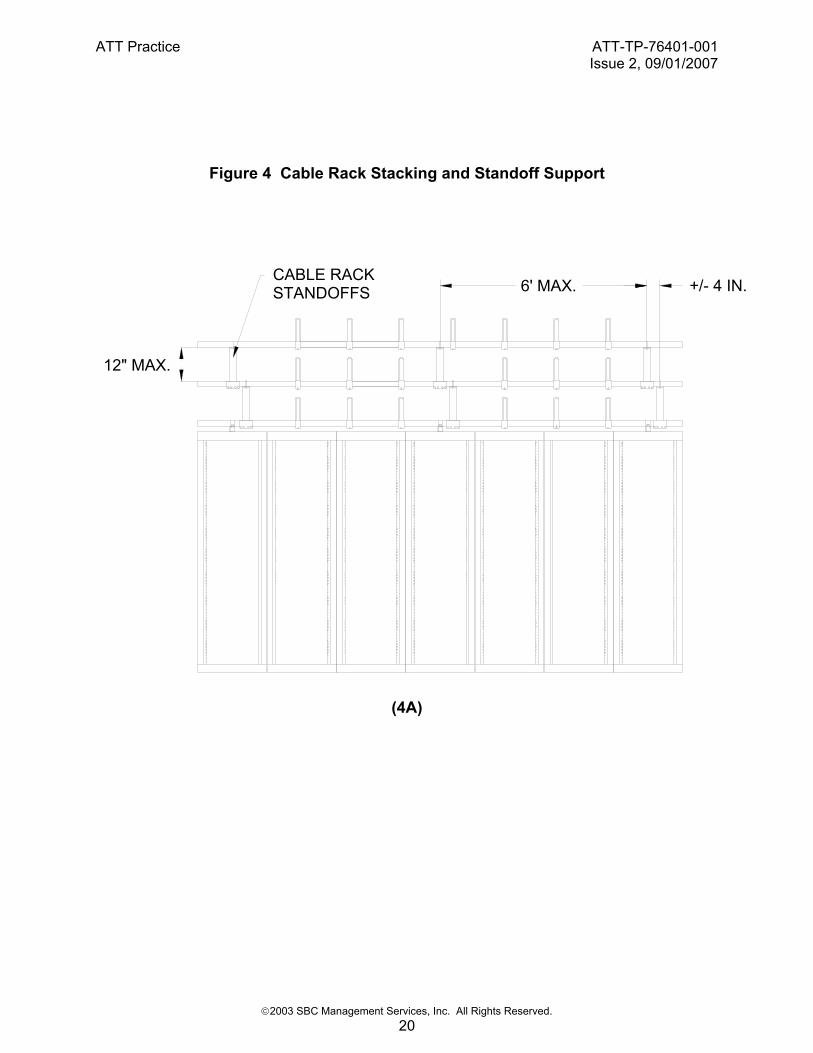
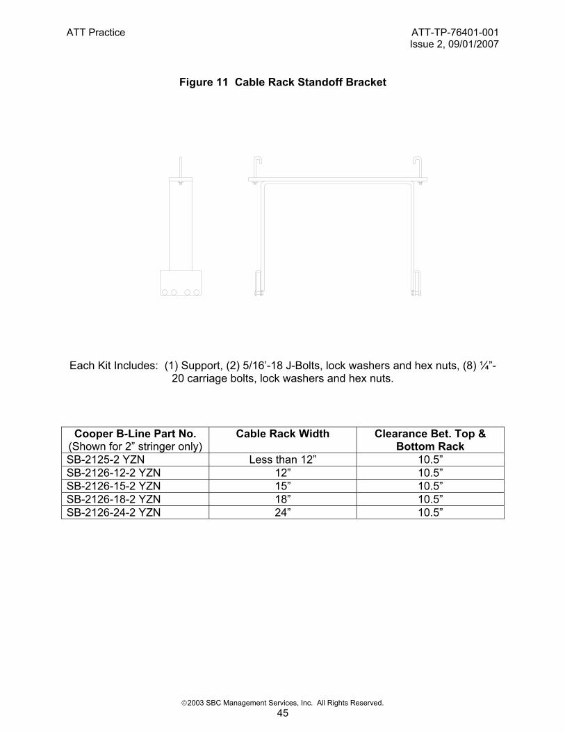
Cross-aisle cable racks attached to lineup cable racks per Fig. 6B are considered adequately supported if the cross aisle rack is 6-feet or less in length. Cross aisle racks longer than 6-feet require support placed mid-span below the rack. The support may be provided by building floor secured stanchion or pipe stands where cable rack lateral displacement will not be likely. 4.2. Stacked Racks For the cabinet supported cable rack environment, additional levels of lineup cable racks may be stacked vertically with standoff support brackets as shown in Figure 11 and 11A. The maximum number of cable rack levels permitted in stacked arrangement shall be three at no more than 12 inches between top of lower rack to bottom of upper rack as shown in Figure 4. Standoff supports as shown in Figs. 11 and 11A are the only configuration acceptable for creating higher level of cable rack run. Standoff supports shall be provided at intervals of no greater than 6 feet span distance. Standoffs to each vertical level shall be placed within ±4 inches of centerline from lower standoff to upper standoff. Lower level standoff shall be located within ±4 inches of cabinet support channel. Stacking cable racks are different than offsetting cable racks to provide clearance of horizontal cable rack run over obstructions. Offsetting methods shown in Figures 6F and 8A shall not be used to stack additional levels of parallel cable rack runs over cabinets. Only standoff brackets can be used to stack parallel runs of upper level cable racks. Studded up arrangements shall never be used to stack another level of cable rack run. 4.3. Racks On Walls and Columns 4.3.1. Vertical Racks Fig. 10D shall be used when vertical cable racks must be fastened to building walls or columns. Each section of vertical rack shall have a minimum of two Fig. 10D supports with a maximum spacing between supports not to exceed 5 feet. The Fig. 10D support arrangement is not intended for heavily loaded cable runs. Vertical racks fastened to building walls or columns which could ultimately support a large amount of cabling shall be terminated at the floor as shown in Fig. 9C. Vertical cable racks attached to building walls or columns shall not be physically connected to a horizontal run of cable rack. A minimum distance of 6 inches shall be provided between the end of a horizontal cable rack and a continuing (cable wise) run of vertical cable rack that is attached to a building wall or column. 4.3.2. Horizontal Racks Where it is necessary to provide for small amounts of cable run horizontally along a building wall, the cable rack may be supported to the building wall as shown in Fig. 10E. Spacing of supports shall not exceed 5 feet. Fig. 10G shall be used for cable rack support when wider than 5 inch cable racks are used, where Fig. 10E cable pileups may exceed 2 inches. Fig. 10E support arrangements require a load bearing building surface. Fig. 10G shall be provided and installed with three ½ inch diameter anchors appropriate for wall material per Table E. A wall support bracket shall be provided every 5-feet along the cable rack run. The widest cable rack that may be supported by wall brackets is 12 inches. Cable pileup for wall supported cable racks shall not exceed 6-inches for cable racks carrying switchboard cable and 3 inches for cable racks carrying primary power cables.

ATT Practice ATT-TP-76401-001Issue 2, 09/01/2007
©2003 SBC Management Services, Inc. All Rights Reserved. 14
Table E Wall Anchor Types
Wall Material Anchor Type Hilti P/N Anchorage Reinf. Concrete Hilti HDI 1/2 00045754 ½-13 x 1in. HHCS
Hollow Block Toggle Bolt 1/2 00066366 Included Hollow Block Adhesive HIT-HY20 00256479 Adhesive
00088979 ½ Rod 00020951 ½ Screen
Included
Reinf. Brick Hilti HDI 1/2 00045754 ½-13 x 1in.HHCS Plaster ½”x6” Wood Lagbolt
4.4. Cable Racks On Floors Cable racks placed on floors require Fig. 10F fastenings to restrain their possible movement. A pair of Fig. 10F fastenings shall be provided for each cable rack in-line junction, for each section of rack ≥2 feet in length, and at the ends of cable rack runs. For safety reasons the fastening should be placed on the inside of the cable rack stringers as shown in Fig. 10F.
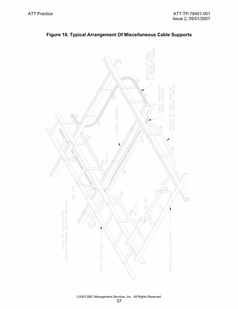
5. MISCELLANEOUS CABLE SUPPORTS
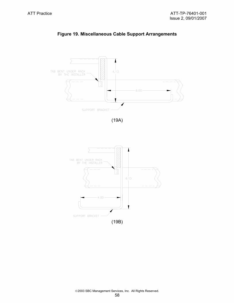
Power cable support brackets or wire support brackets secured to the cable rack stringers may be provided where required. Support brackets shall be spaced no more than 12 inches apart along cable rack stringers. Support brackets shall not extend below cable racks to where floor to bottom of bracket height is less than 7 feet. Support brackets shall have positive means for securing bracket to the cable rack stringer such as bent tabs or screw tightening clamps. Fiber optic cable management may require support brackets for fiber guide. Fiber guide support brackets may be attached to cable rack stringers with positive means of securing the bracket to the stringers such as screw tightening clamp.
6. CABLE RACK PANS AND CABLE RETAINING BRACKETS
6.1. Cable Rack Used For Unsecured Cable Fig. 1 ladder type cable racks equipped with metallic pans and straight zinc plated formed wire type bolt-on cable retaining brackets as shown in Fig. 20 shall be used for unsecured cable applications. 6.2. Cable Rack Horns Cable rack horns shall be provided in a height not exceeding the maximum allowable cable pileup of the cable racks they are used with. Generally, straight horns that extend 8 inches above cable racks shall be provided for racks. Horns shall be provided on opposing stringers of cable racks and spaced no more than 18 inches apart. Cable rack support hardware located along run of cable rack such as sleeved threaded rods can take the place of a cable horn. Additional cable rack horns shall be provided as necessary along lengths of cable rack and at cable rack intersections as necessary to confine cable within the width of cable racks. Cable rack horns shall not be located within the span of cable rack intersections or where they may be considered a hazard to cable. Horns that mount on the sides of cable racks and include an integral means of providing cable support/separation may be used where necessary instead of supplemental cable racks for the support of lightweight interconnection media such as fiber optic cabling. Such horns are

ATT Practice ATT-TP-76401-001Issue 2, 09/01/2007
©2003 SBC Management Services, Inc. All Rights Reserved. 15
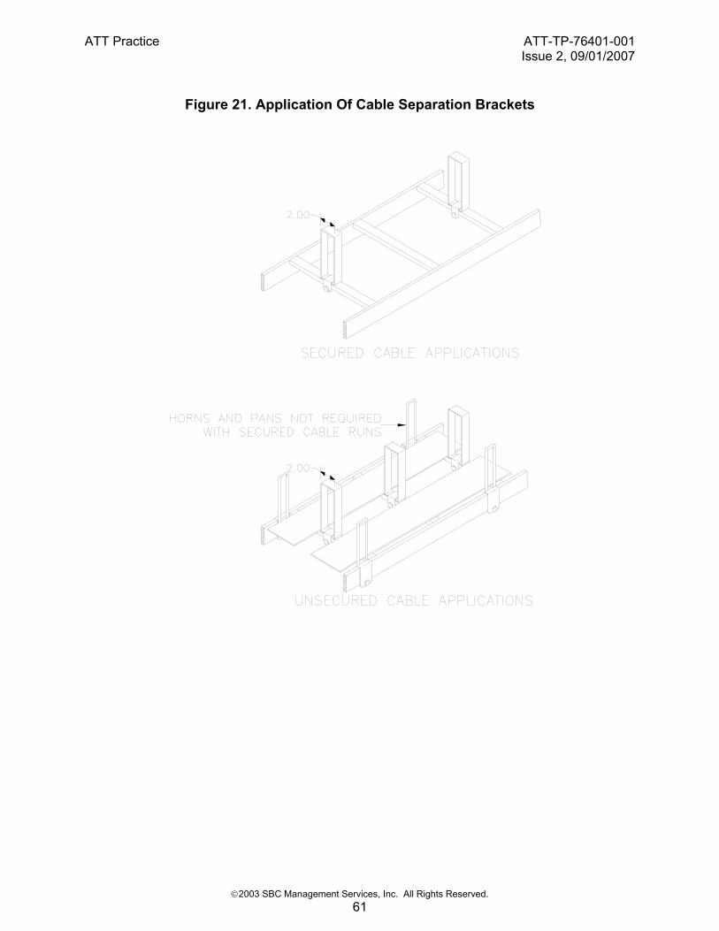
generally referred to as compartment horns and shall be installed on racks no more than 9 inches apart. 6.3. Separating Parallel Runs Of Cable Single-piece bolt-on brackets similar to that shown in Fig. 21 may be used when it is necessary to use a single cable rack for cable that should otherwise not be installed together for electrical reasons. In such cases cable separation brackets shall provide a minimum separation of 2 inches. Separation brackets shall be installed on cross-strap of unsecured cable racks and on every other cross-strap of secured cable racks. 6.4. Cable Rack Pans Cable rack pans may be aluminum or steel having a gray finish and shall be provided in widths appropriate for the width of cable rack they are used with. The use of multiple pans to span the width of cable racks is not permitted. Cable rack pans shall overlap along the length of cable runs in a manner that minimizes end-of-pan sag under cable racks. Cable rack pans shall not be installed through fire rated building surfaces. Installed cable rack pans shall not present a hazard to people or cable. Edge protection shall be applied to the ends of pans that are cut by hand into shorter lengths, the ends of dead-ended pans at a horizontal to vertical change in cable level (refer to Fig. 20), and to the ends of pans considered to be a safety hazard to people or cable. Pans cut in the field shall include an approximate 1/4” radius at their corners to avoid curled edges. 7.0 LIGHT FIXTURE SUPPORT 7.1 Supporting Light Fixtures Along Aisles Light fixtures shall be securely and firmly attached to auxiliary framing channels or strut channels. Fixtures shall not be secured to cable rack stringer. Use hardware that provides a positive attachment to the channels not relying on friction, gravity or other non-positive means to secure the fixtures. Light fixture shall be secured in a manner to not swing or be permitted to move in any direction. Span between fixture supports shall not exceed 6 feet distance. At minimum, light fixtures in aisles shall have 7’-0” clearance between building floor and the lowest underside part of the fixture. Light fixtures shall be AT&T approved energy efficient fluorescent tube units. Tube guards shall be provided to prevent accidental harm to tubes and unintended release of tube. Lumicool type fixtures combining light fixture with HVAC diffusers are not required in the Internet Services or IPTV environment because of the improved room cooling methods used in these facilities.

ATT Practice ATT-TP-76401-001Issue 2, 09/01/2007
©2003 SBC Management Services, Inc. All Rights Reserved. 16
8. FIGURES AND SKETCHES

ATT Practice ATT-TP-76401-001Issue 2, 09/01/2007
©2003 SBC Management Services, Inc. All Rights Reserved. 17
Figure 1. Typical Ladder Type Cable Rack Construction

ATT Practice ATT-TP-76401-001Issue 2, 09/01/2007
©2003 SBC Management Services, Inc. All Rights Reserved. 18
Figure 2. Typical Cross Sectional Cable Rack Designation Scheme

ATT Practice ATT-TP-76401-001Issue 2, 09/01/2007
©2003 SBC Management Services, Inc. All Rights Reserved. 19
Figure 3. Cable Rack Configuration Over Cabinets
LINEUPCABLERACK
CROSSAISLE
CABLERACK
CA
BIN
ET
FRO
NT C
ABIN
ET FRO
NT
CHANNELSUPPORT
ATT Practice ATT-TP-76401-001Issue 2, 09/01/2007
©2003 SBC Management Services, Inc. All Rights Reserved. 20
Figure 4 Cable Rack Stacking and Standoff Support
CABLE RACKSTANDOFFS +/- 4 IN.
12" MAX.
6' MAX.
(4A)

ATT Practice ATT-TP-76401-001Issue 2, 09/01/2007
©2003 SBC Management Services, Inc. All Rights Reserved. 21
FRONT
CROSS AISLE RACK
6'-0" MAX.
(4B) Cable Rack Stacking and Cross Aisle Racks
ATT Practice ATT-TP-76401-001Issue 2, 09/01/2007
©2003 SBC Management Services, Inc. All Rights Reserved. 22
Figure 5. Standard In-Line Cable Rack Junctions

ATT Practice ATT-TP-76401-001Issue 2, 09/01/2007
©2003 SBC Management Services, Inc. All Rights Reserved. 23

ATT Practice ATT-TP-76401-001Issue 2, 09/01/2007
©2003 SBC Management Services, Inc. All Rights Reserved. 24

ATT Practice ATT-TP-76401-001Issue 2, 09/01/2007
©2003 SBC Management Services, Inc. All Rights Reserved. 25

ATT Practice ATT-TP-76401-001Issue 2, 09/01/2007
©2003 SBC Management Services, Inc. All Rights Reserved. 26
Figure 6. Standard Cable Rack Intersections

ATT Practice ATT-TP-76401-001Issue 2, 09/01/2007
©2003 SBC Management Services, Inc. All Rights Reserved. 27

ATT Practice ATT-TP-76401-001Issue 2, 09/01/2007
©2003 SBC Management Services, Inc. All Rights Reserved. 28

ATT Practice ATT-TP-76401-001Issue 2, 09/01/2007
©2003 SBC Management Services, Inc. All Rights Reserved. 29
ATT Practice ATT-TP-76401-001Issue 2, 09/01/2007
©2003 SBC Management Services, Inc. All Rights Reserved. 30
ATT Practice ATT-TP-76401-001Issue 2, 09/01/2007
©2003 SBC Management Services, Inc. All Rights Reserved. 31

ATT Practice ATT-TP-76401-001Issue 2, 09/01/2007
©2003 SBC Management Services, Inc. All Rights Reserved. 32
ATT Practice ATT-TP-76401-001Issue 2, 09/01/2007
©2003 SBC Management Services, Inc. All Rights Reserved. 33
ATT Practice ATT-TP-76401-001Issue 2, 09/01/2007
©2003 SBC Management Services, Inc. All Rights Reserved. 34
Figure 7. Standard In-line Cable Rack Turns
ATT Practice ATT-TP-76401-001Issue 2, 09/01/2007
©2003 SBC Management Services, Inc. All Rights Reserved. 35

ATT Practice ATT-TP-76401-001Issue 2, 09/01/2007
©2003 SBC Management Services, Inc. All Rights Reserved. 36
Figure 8. Standard Cable Rack Offsets
ATT Practice ATT-TP-76401-001Issue 2, 09/01/2007
©2003 SBC Management Services, Inc. All Rights Reserved. 37
Figure 9. Standard Cable Rack Terminations

ATT Practice ATT-TP-76401-001Issue 2, 09/01/2007
©2003 SBC Management Services, Inc. All Rights Reserved. 38

ATT Practice ATT-TP-76401-001Issue 2, 09/01/2007
©2003 SBC Management Services, Inc. All Rights Reserved. 39

ATT Practice ATT-TP-76401-001Issue 2, 09/01/2007
©2003 SBC Management Services, Inc. All Rights Reserved. 40

ATT Practice ATT-TP-76401-001Issue 2, 09/01/2007
©2003 SBC Management Services, Inc. All Rights Reserved. 41
Figure 10

ATT Practice ATT-TP-76401-001Issue 2, 09/01/2007
©2003 SBC Management Services, Inc. All Rights Reserved. 42

ATT Practice ATT-TP-76401-001Issue 2, 09/01/2007
©2003 SBC Management Services, Inc. All Rights Reserved. 43

ATT Practice ATT-TP-76401-001Issue 2, 09/01/2007
©2003 SBC Management Services, Inc. All Rights Reserved. 44
ATT Practice ATT-TP-76401-001Issue 2, 09/01/2007
©2003 SBC Management Services, Inc. All Rights Reserved. 45
Figure 11 Cable Rack Standoff Bracket
Each Kit Includes: (1) Support, (2) 5/16’-18 J-Bolts, lock washers and hex nuts, (8) ¼”-20 carriage bolts, lock washers and hex nuts.
Cooper B-Line Part No. (Shown for 2” stringer only)
Cable Rack Width Clearance Bet. Top & Bottom Rack
SB-2125-2 YZN Less than 12” 10.5” SB-2126-12-2 YZN 12” 10.5” SB-2126-15-2 YZN 15” 10.5” SB-2126-18-2 YZN 18” 10.5” SB-2126-24-2 YZN 24” 10.5”
ATT Practice ATT-TP-76401-001Issue 2, 09/01/2007
©2003 SBC Management Services, Inc. All Rights Reserved. 46
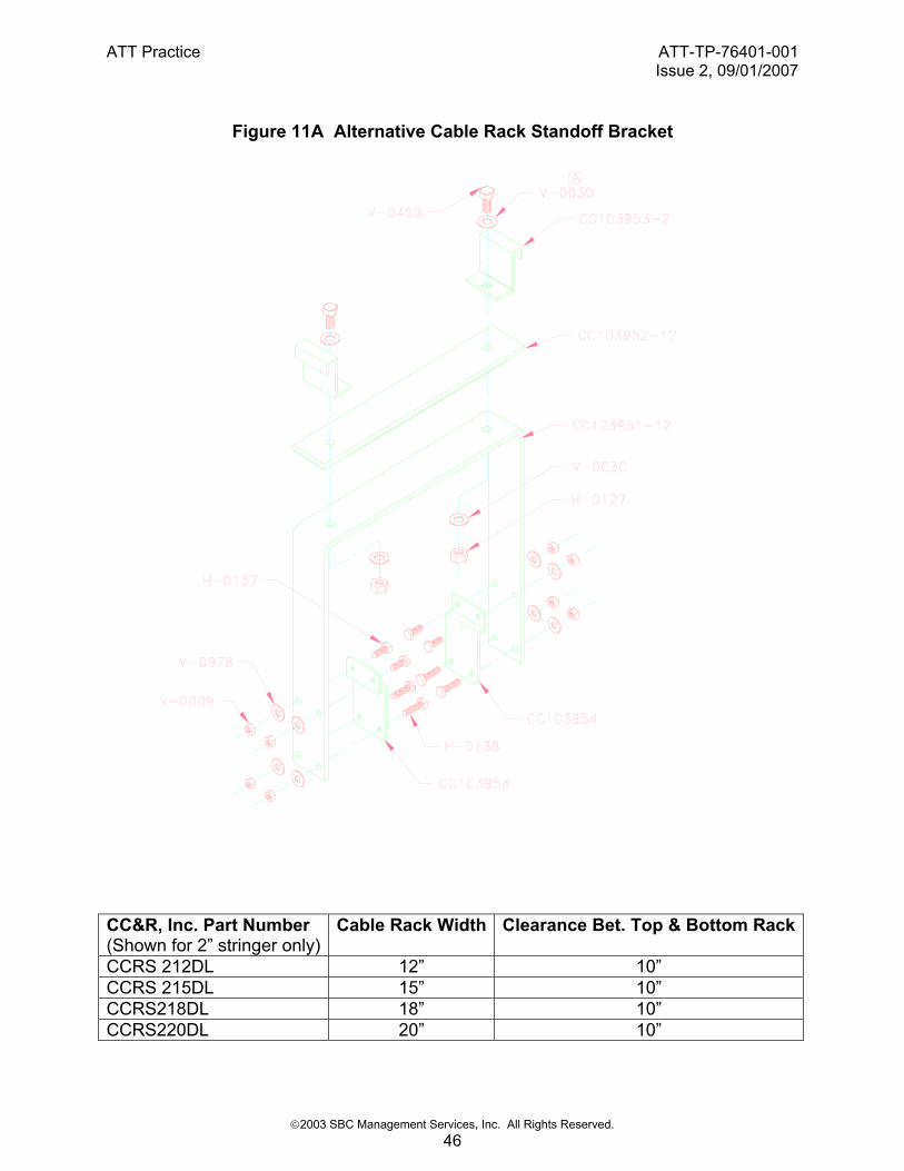
Figure 11A Alternative Cable Rack Standoff Bracket
CC&R, Inc. Part Number (Shown for 2” stringer only)
Cable Rack Width Clearance Bet. Top & Bottom Rack
CCRS 212DL 12” 10” CCRS 215DL 15” 10” CCRS218DL 18” 10” CCRS220DL 20” 10”

ATT Practice ATT-TP-76401-001Issue 2, 09/01/2007
©2003 SBC Management Services, Inc. All Rights Reserved. 47
Figure 12 Cabinet Support and Cable Rack Hold Down
CABINET TOP CHANNELSUPPORT AND RACK
HOLD DOWN KITSHILTI PART NUMBER
3414051 - 36" CHANNEL3414052 - 40" CHANNEL
EQUIPMENT CABINET
Each Hilti Kit Includes: (1) Hilti HS-158-12 channel (36” or 40” long), (2) ½”-13 x 1-1/4” long capscrew, (4) lockwashers, (4) flat washers, (2) rack hold down brackets, (2) ½”-13 x 1” long capscrews, (2) lockwashers, (2) flat washers, (2) Hilti ½” channel nuts. Kits designed for CC&R 36” or 40” Standard Cabinets (Part Nos. CCVC 1936, CCVC 1940, CCGC 2336, CCGC 2340) . Kits may be used with other cabinets, however, field drilling two 9/16’ holes in cabinet top may be required for securing top channel and field cutting channels may be required to fit cabinet depth..
ATT Practice ATT-TP-76401-001Issue 2, 09/01/2007
©2003 SBC Management Services, Inc. All Rights Reserved. 48
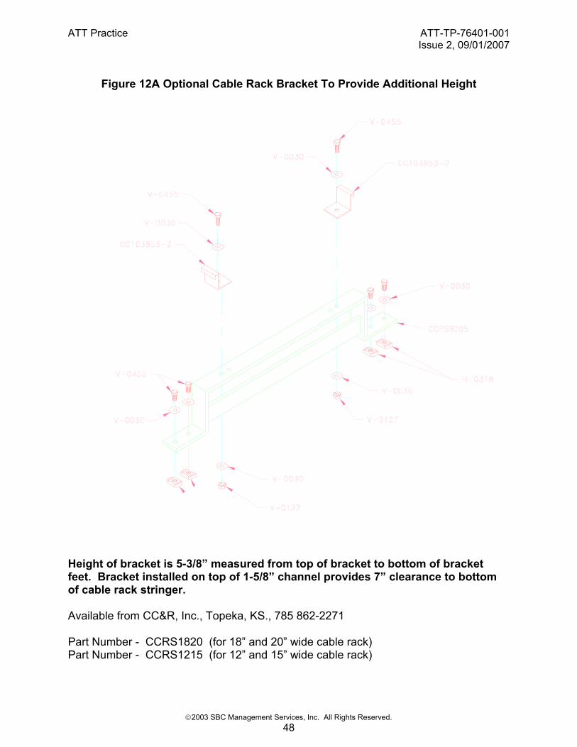
Figure 12A Optional Cable Rack Bracket To Provide Additional Height
Height of bracket is 5-3/8” measured from top of bracket to bottom of bracket feet. Bracket installed on top of 1-5/8” channel provides 7” clearance to bottom of cable rack stringer. Available from CC&R, Inc., Topeka, KS., 785 862-2271 Part Number - CCRS1820 (for 18” and 20” wide cable rack) Part Number - CCRS1215 (for 12” and 15” wide cable rack)

ATT Practice ATT-TP-76401-001Issue 2, 09/01/2007
©2003 SBC Management Services, Inc. All Rights Reserved. 49
Figure 12B Assembly - Bracket To Cabinet Top Channel

ATT Practice ATT-TP-76401-001Issue 2, 09/01/2007
©2003 SBC Management Services, Inc. All Rights Reserved. 50
Figure 12C Optional Studded Up Cable Rack To Provide Additional Height
6" Max.STEEL SLEEVE REQ.D5/8" DIA. THD.ROD
CABLE RACK
DATA CABINET
OVER EXPOSED THREADS
END OF CABINET VIEW
AUX. CHANNEL ORUNISTRUT CHANNEL

ATT Practice ATT-TP-76401-001Issue 2, 09/01/2007
©2003 SBC Management Services, Inc. All Rights Reserved. 51
FIGURE 12D Optional Parallel Channel Runs To Provide Flexible Location Of Cable Rack Supports
(2) UNISTRUT CHANNELSP-1000 1-5/8" HEIGHT
PARALLEL TO LINEUP
CABLE RACK SUPPORT
EQUIPMENT CABINETS
SECURE CHANNEL TOTOP OF CABINET WITH
MIN. 1/2" HHCS

ATT Practice ATT-TP-76401-001Issue 2, 09/01/2007
©2003 SBC Management Services, Inc. All Rights Reserved. 52
Figure 13 Cabinet Support Channels
40
371516
1 116 1 1
16
36
331516
1 116 1 1
16
11516
2 116Ø 9
16
ATT Practice ATT-TP-76401-001Issue 2, 09/01/2007
©2003 SBC Management Services, Inc. All Rights Reserved. 53
Figure 14 Four Post Cabinet Cable Rack Support
TOP CHANNEL
SECURED TOCABINET
CABLE RACK

ATT Practice ATT-TP-76401-001Issue 2, 09/01/2007
©2003 SBC Management Services, Inc. All Rights Reserved. 54
Figure 15 Deep Upright Style Two-Post Framework Cable Rack Support
DEEP UPRIGHT
TOP CHANNEL
SECURE TOTOP OF FRAME
CABLE RACK
ATT Practice ATT-TP-76401-001Issue 2, 09/01/2007
©2003 SBC Management Services, Inc. All Rights Reserved. 55
Figure 16 Back to Back Two-Post Frameworks Cable Rack Support
RELAY RACKRELAY RACK
CABLE RACK
CHANNEL
SECURE TOTOP OF FRAMES
ATT Practice ATT-TP-76401-001Issue 2, 09/01/2007
©2003 SBC Management Services, Inc. All Rights Reserved. 56
Figure 17. Additional Cable Support To Prevent Cable Sag
ATT Practice ATT-TP-76401-001Issue 2, 09/01/2007
©2003 SBC Management Services, Inc. All Rights Reserved. 57
Figure 18. Typical Arrangement Of Miscellaneous Cable Supports
ATT Practice ATT-TP-76401-001Issue 2, 09/01/2007
©2003 SBC Management Services, Inc. All Rights Reserved. 58
Figure 19. Miscellaneous Cable Support Arrangements
(19A)
(19B)

ATT Practice ATT-TP-76401-001Issue 2, 09/01/2007
©2003 SBC Management Services, Inc. All Rights Reserved. 59
(19C)

ATT Practice ATT-TP-76401-001Issue 2, 09/01/2007
©2003 SBC Management Services, Inc. All Rights Reserved. 60
Figure 20. Panned And Horned Cable Rack Used For Unsecured Cable Applications
ATT Practice ATT-TP-76401-001Issue 2, 09/01/2007
©2003 SBC Management Services, Inc. All Rights Reserved. 61
Figure 21. Application Of Cable Separation Brackets