attachment 1 - clinton power station setpoint calculation ... · 2 ,supercedes m cid_ c-cps-143 3 -...
TRANSCRIPT

ATTACHMENT I
Clinton Power Station Setpoint Calculation IP-C-0087

CALCULATION COVER SHEET Page 1 of 42
IC INSED JIP-C-0087 I0 1-- IA ]DEPT DIV CALCULATION NO REVISION ADDENDUM VOLUME
TITLE: SETPOINT.CALCULATION FOR.SUPRESSJON POOL HIGH - HPCS; TRANSMITTERS 1E22N055.C&G..
SIGNATURE BLOCK
PREPARED BY C. .V. .HALLETTPR 44j,,t5,,T Ch
DATE SIGNATURE
CIIECKEDBY J. M. ASHCRAFT--- .2"
7 IZVI-1 aJi QA 2nDDATE SI ATUR
REVIEWED BY J. M. ASHCRAFT..._.A4fJVnItA/PRINT~
.- LZI / 13S-DATE SI9TXATURE
APPROVED BY P. R. .MARCUM _____-
7 ini•?l "4a -DATE SIGNATURE
OWNER'S REVIEW NON-CIS CALCREVIEWED BY. - ....j /A PRINT
DATE SIGNATURE
CORP PREPARED TIIIS CALC: CPS LTY NO [CONFIRMATION REQUIRED
YES/NO: [NO PAGE NO(S) I i CONFIRMED: [Field Work To Be Performed Per ECN Listed Below
ECN NO DESIGN CID UPDATEDIve RELEASED DATE
4P........ ..
iE?/ 70 7ZL- D .. ..... ___ _...- __.__.-_. __..... _._
ECN's listed above shall include 'Volume Report' as Affected Documents.
'I READY FOR INCORPORATION
NO . ASSIGNED TO: A DATE RFI:
C4
ACN
Il
YESINOJ(NIA):
COMMENTS:
A/Zi 76522.. II is treeS ka."5 X'rAlt 7S67ZI-v?- to 9A,,,ek#5 i ~~i r vsa
CALCULATION BATCH LIST(May use computer print out and attach it with cover sheet or specify it's location if provided elsewhere in the calculation.)
IS TIlILS A PARENT CALC: YES %/ .No,DEPENDENT CALCULATIONS (Enter either a Parent, Revision, Alias. Addendun or Volume In the relationship column)
CTrA Tl TC
# RELATIONSHIP
1 VOLUME___.
DEPT DIV
C NSE[CALCULATION NO REV ADD VOL BEFORE AFTER
) IP-C-0087 0 --- A U A.. ~~~~~~~. .. . -. .. ..... .._. ... ._. _....._ ...... ..
_ I _ _ ! .-
IMPACTED CALCULATIONS TEnter either an Input, Output, Supplements, or Supersedes in the relationship column)
_. _ . .
STATUS# RELATIONSHIP DEPT DIV CALCULATION NO REV ADD VOL BEFORE AFTER
t ISUPERCEDES M CID CI-CPS-142 3. 3- - A S2 ,SUPERCEDES M CID_ C-CPS-143 3 - --- -- A S3 INPUT C NSED IP-C-0089 0 i -A A
REFERENCED CALCULATIONS (Not Included as Dependent or Lnpacted Calculations. Enter Referenced in the relationship column) |ACNI III
RELATIONSHIP DEPT DIV CALCULATION NOI _ : : : .: - - . - . .
REV ADD VOL
. .,1.. . I
- 1. _. .. . ......... ; ..
a .- .-I
i

CALCULATION COVER SHEET (Continued) Page 2 of 42
I C I NSED I IP-C-0087 0 I -- I A IDEPT DIV CALCULATION NO REVISION ADDENDUM VOLUME
System Code(s) (or NA): HP. ..
Equipment Identification No. (EINs) (or NA): 1 E22N055C&G; .1 E22N655C&G .. - -
... ._. _.
Support Number(s) (or NA): NA
Historic [ITemporary: II
_____Location (BldglElev/Area (or NA): NA______ -
Microfiche Attached: Yes [] NoFZ] Topic Code: M98
ACNI III
NON-CALC INPUTS/OUTPUTS/REFERENCES(Specify the Locatdon, if provided elsewhere in the calculation)
(Identify in Relationship Column)
DOC DOC SHT REV Relation-# TYPE NO NO NO DATE DESCRIPT]ON shipNO NO DATE(I,O.R)
= = = SECTION 4
SECTION5 0SECTION 6 R
I I_
4 4 I-4 4- 4- 4
04
_=~~ _ -
= ___ _ ______ . .
==I
_ _L_ = -- I
REVISION HISTORY
SC. NLSED- IPC.Q087 -.I* DEP DIV
Page 3 of 4--
O - AREVISION ADDENDUM VOLUMECALCULATION NO
REVISION OBJECTIVE: QRI IIAL CALCULATION ..
. ._ . . _. _ -
_ _ _ . ... _
_ . .
_ _ . . .
WHAT INITIATED CHANGE: NA.. _____ _ .................... _ . .... .... ...
.....__.............._
__ _
.... . . - ... ...
C>
AFFECTED PAGES: NA. -- 2
,.Z. .. z.
_ . ..
.
.... . .. -
. _. .
. . . ~ ~ __ ... . _ . _. ..
Note: Preparer provide explicit instructions for volume/Addendum Calculations to be Incorporated using'Administrative Revisions".
DEPT/DIV CALCULATION NO. IP-C-0087 REVISION 0 SHEETC/NSED VOLUME A 4 of 42
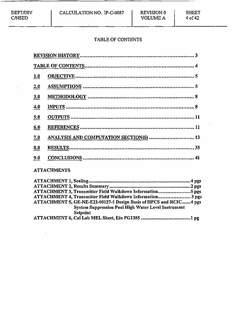
TABLE OF CONTENTS
RE0ISION HISTORY ...................................................... 3
TA4 LE OF CON TEN lr1.S ... .................................. 4
6.0 OBJECTIV .....S ........................... 1
3.0 MvE3THODOLOGY ................................... 8
4.0 INPUT~lS ..................................... ..... 8
5.0 O U T.P UTS ......................................... 1
6.0 R E lE R EN CE1S ...................................... 1
7.0 ANALYSIS AND COMPUTATION SECTION(S) .13
8.0 RESS... 35
9.0 CONCLUSIONS .............................. 41
ATTACHMENTS
ATTACHMENT 1, Scaling .......................................................... 4 pgsATTACHMENT 2, Results Summary.. . . . ................................... 2 pgsATTACHMENT 3, Transmitter Field Walkdown Information . ............... 5 pgsATTACHMENT 4, Transmitter Field Walkdown Information .................. 3 pgsATTACHMENT 5, GE-NE-E22-00127-1 Design Basis of HPCS and RCIC ....... 4 pgs
System Suppression Pool High Water Level InstrumentSctpoint
ATTACHMENT 6, Cal Lab MEL Sheet, Ein PG1385 .......................................... 1 pg

DEPT/DIVC/NSED
CALCULATION NO. IP-C-0087 REVISION 0VOLUME A
SHEET5 of 42
1.0 OBJECTIVE
1.1 To determine the instrument uncertainty, setpoint, and Allowable Valuefor Suppression Pool High - HPCS, instruments 1 E22N055C & G andIE22N655C & G respectively.
1.2 This calculation evaluates the adequacy of the current setpoints inrelationship to the results of 1.1 above.
1.3 The setpoint and Allowable Value for Suppression Pool High - HPCS wasoriginally calculated and transmitted in S&L Calculations CI-CPS-142 and143. This calculation supercedes S&L Calculations CI-CPS-142 and 143(References 6.8 & 6.9).
2.0 ASSUMPTIONS
2.1 Published instrument vendor specifications are considered to be 2cr valuesunless specific information is available to indicate otherwise.(Ref 6. 1, Section 4.1.3.4).
2.2 Temperature, humidity, power supply, and ambient pressure errors havebeen incorporated when provided by the manufacturer. Otherwise, theseerrors are assumed to be included in the manufacturer's accuracy orrepeatability (Ref. 6.1, Section 4.3.1 and Appendix A, Section A.2.1).
2.3 Changes in ambient humidity are assumed to have a negligible effect onthe uncertainty of the instruments used in these loops (Ref. 6.1, AppendixI, Section 1.2).
2.4 Normal radiation induced errors have been incorporated when provided bythe manufacturer. Otherwise, these errors are assumed to be small andcapable of being adjusted out each time the instrument is calibrated.Therefore, unless specifically provided, normal radiation errors can beassumed to be included within the instrument drift errors (Ref. 6.1,Appendix I, Section I.1).
DEPT/DIV CALCULATION NO. IP-C-0087 REVISION 0 SHEETCINSED VOLUME A 6 of 42
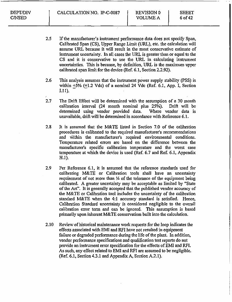
2.5 If the manufacturer's instrument performance data does not specify Span,Calibrated Span (CS), Upper Range Limit (URL), etc. the calculation willassume URL because it will result in the most conservative estimate ofinstrument uncertainty. In all cases the URL is greater than or equal to theCS and it is conservative to use the URL in calculating instrumentuncertainties. This is because, by definition, URL is the maximum uppercalibrated span limit for the device (Ref. 6.1, Section 2.2.92).
2.6 This analysis assumes that the instrument power supply stability (PSS) iswithin +5% (+1.2 Vdc) of a nominal 24 Vdc (Ref. 6.1, App. I, Section1.1 I).
2.7 The Drift Effect will be determined with the assumption of a 30 monthcalibration interval (24 month nominal plus 25%). Drift will bedetermined using vendor provided data. Where vendor data isunavailable, drift will be determined in accordance with Reference 6.1.
2.8 It is assumed that the M&TE listed in Section 7.0 of the calibrationprocedures is calibrated to the required manufacturer's recommendationsand within the manufacturer's required environmental conditions.Temperature related errors are based on the difference between themanufacturer's specific calibration temperature and the worst casetemperature at which the device is used (Ref. 6.7 and Ref. 6.1, AppendixH.l).
2.9 Per Reference 6.1, it is assumed that the reference standards used forcalibrating M&TE or Calibration tools shall have an uncertaintyrequirement of not more than 1/4 of the tolerance of the equipment beingcalibrated. A greater uncertainty may be acceptable as limited by "Stateof the Art". It is generally accepted that the published vendor accuracy ofthe M&TE or Calibration tool includes the uncertainty of the calibrationstandard M&TE when the 4:1 accuracy standard is satisfied. Hence,Calibration Standard uncertainty is considered negligible to the overallcalibration error term and can be ignored. This assumption is basedprimarily upon inherent M&TE conservatism built into the calculation.
2.10 Review of historical maintenance work requests for the loop indicates theeffects associated with EMI and RFI have not resulted in equipmentfailure or degraded performance during the life of the plant. In addition,vendor performance specifications and qualification test reports do notprovide an instrument error specification for the effects of EMI and RFI.As such, any effect related to EMI and RFI are assumed to be negligible.(Ref. 6.1, Section 4.3.1 and Appendix A, Section A.2.1).
DEPT/DIV CALCULATION NO. IP-C-0087 REVISION 0 SHEETCINSED VOLUME A 7 of 42
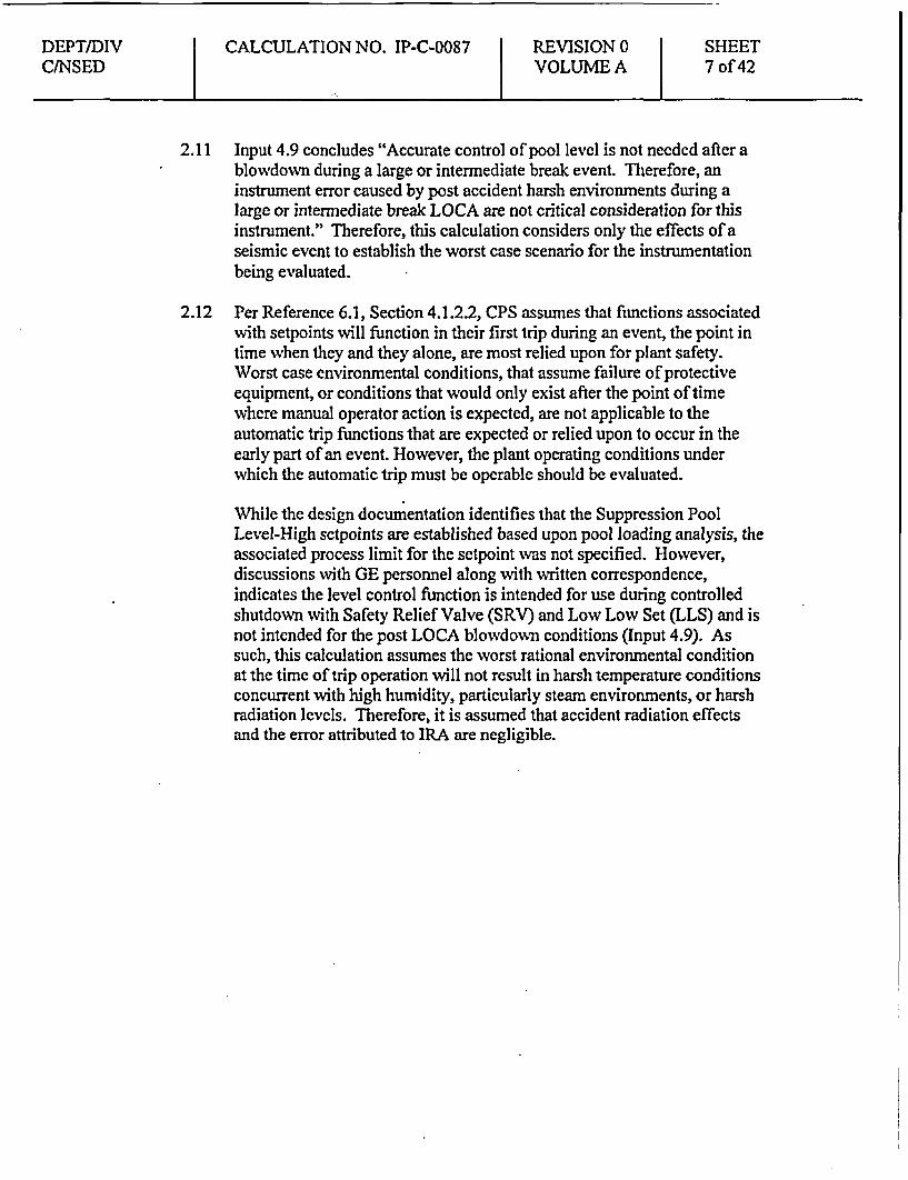
2.11 Input 4.9 concludes "Accurate control of pool level is not needed after ablowdown during a large or intermediate break event. Therefore, aninstrument error caused by post accident harsh environments during alarge or intermediate break LOCA are not critical consideration for thisinstrument." Therefore, this calculation considers only the effects of aseismic event to establish the worst case scenario for the instrumentationbeing evaluated.
2.12 Per Reference 6.1, Section 4.1.2.2, CPS assumes that functions associatedwith setpoints will function in their first trip during an event, the point intime when they and they alone, are most relied upon for plant safety.Worst case environmental conditions, that assume failure of protectiveequipment, or conditions that would only exist after the point of timewhere manual operator action is expected, are not applicable to theautomatic trip functions that are expected or relied upon to occur in theearly part of an event. However, the plant operating conditions underwhich the automatic trip must be operable should be evaluated.
While the design documentation identifies that the Suppression PoolLevel-High sctpoints are established based upon pool loading analysis, theassociated process limit for the setpoint was not specified. However,discussions with GE personnel along with written correspondence,indicates the level control function is intended for use during controlledshutdown with Safety Relief Valve (SRV) and Low Low Set (LLS) and isnot intended for the post LOCA blowdown conditions (Input 4.9). Assuch, this calculation assumes the worst rational environmental conditionat the time of trip operation will not result in harsh temperature conditionsconcurrent with high humidity, particularly steam environments, or harshradiation levels. Therefore, it is assumed that accident radiation effectsand the error attributed to IRA are negligible.

DEPT/DIV CALCULATION NO. IP-C-0087 REVISION 0 SHEETC/NSED VOLUME A 8 of 42
3.0 METHODOLOGY
This calculation will determine the instrument uncertainty associated with theSuppression Pool High - HPCS differential pressure transmitter(s). TheEvaluation will determine the loop setpoint and Allowable Value for theSuppression Pool High - HPCS switchover function on high level. Instrumentuncertainty will be detennined in accordance with Reference 6.1, CI-01.00,"Instrument Setpoint Calculation Methodology." The evaluation will thencompare the current setpoint and Allowable Value with the results determined bythis calculation.
M&TE error will be determined from the results of Calculation IP-C-0089 (Input4.6.1) which uses building temperature minimum and maximums to develop theuncertainty, and review of the corresponding loop and device calibrationprocedures (Input 4.16).
Per Reference 6.1, Head Correction is determined by evaluating design drawings,survey data, and/or walk down data as applicable.
4.0 INPUTS
4.1 P&IDs
4.1.1 MIO-9074, sheet 3, Rev. B, "P&ID/C & I High PressureCore Spray System (HP)".
4.2 Technical Manuals
4.2.1 K2801-0175, Tab 17, Rev. 34, "Instruction Manual, ModelPD3218 Remote Diaphragm Differential PressureTransmitter, DMM-2340" dated August, 1984.
4.3 System Design Criteria
4.3.1 DC-ME-09-CP, Rev. 11, "Equipment EnvironmentalDesign Conditions Design Criteria", (Zone Code H-4, MapCode F.2.1, General Area, El. 737'-0", page 60; Zone CodeH-5, Map Code F.1.1, General Area, El. 712'-O", page 60;Zone Code M-24, Map Code D.6.2, Main Control Room &Electric Panel Room, El. 800'-0", page 49).

DEPT/DIV CALCULATION NO. IP-C-0087 REVISION 0 SHEETCINSED VOLUME A 9 of 42
4.4 CPS Drawings
4.4.1 E02-1HP99 Sheet 003, Rev. K, "Schematic Diagram, HighPressure Core Spray System (NSPS)".
4.4.2 E02-IHP99 Sheet 005, Rev. F, "Schematic Diagram, HighPressure Core Spray System (NSPS)".
4.4.3 E02-IHP99 Sheet 006, Rev. D, "Schematic Diagram, HighPressure Core Spray System (NSPS)".
4.4.4 E02-IHP99 Sheet 009, Rev. K, "Schematic Diagram, HighPressure Core Spray System (NSPS)".
4.4.5 M28-1001-05A-K Sheet 001, Rev. R, "Control andInstrumentation Piping Fuel Building Floor EL> 737'-0""
4.4.6 HP-913 Sheet 1, Rev. 3, "Fuel Building High Pressure CoreSpray Piping"
4.4.7 HP-914 Sheet 1, Rev. 4, "Fuel Building High Pressure CoreSpray Piping"
4.4.8 MO 11600 Sheet 6, Rev. A "Environmental Zone MapAuxiliary, Fuel & Containment Basement Floor Plan El707'-6" & 712'-01""
4.4.9 MO 1-1600 Sheet 7, Rev. A "Environmental Zone MapAuxiliary, Fuel & Containment Grade Floor Plan El 737'-O""11
4.4.10 MO 1-1600 Sheet 18, Rev. A "Environmental Zone MapControl Building Main Floor Plan El. 800'-0""
4.4.11 E30-1004-OOA-EI, Rev. F, "Electrical Installation MainControl Room Control Bldg. Main FLR-EL.800'-0""
4.4.12 E03-lP663 Sheet 673, Rev. B, "Internal-External WiringDiagram NSPS Div. 3 Cabinet 1H13-P663"
4.4.13 E03-1P663 Sheet 604, Rev D, "Internal Wiring Diagram,NSPS Div. 1 Cabinet 1H13-P663"
4.5 Passport (D030) INFORMATION ONLY
4.5.1 EIN 1E22NO55C & G, Differential Pressure Transmitters,General Electric (Gould/Statham), Model PD3218-100-38-12-10-56-40
4.5.2 EIN IE22N655C & G, Analog Trip Module, GeneralElectric, Model 147D8505G005
4.5.3 EIN PG1385, Digital Heise, Model 901B, range 0-160inwc, 12/17/92
4.6 Calculations
4.6.1 Calculation IP-C-0089, Rev. O, "M&TE UncertaintyCalculation". I

DEPT/DIV CALCULATION NO. IP-C-0087 REVISION 0 SHEETC/NSED VOLUME A 10 of 42
4.7 Equipment Qualification
4.7.1 EQ-CL069, Rev. 06, Gould PD-3218 Differential PressureTransmitter
4.7.2 SQ-CL603, Rev. 15, Qualification for MCR Panels.4.7.3 SQ-CL689, Rev. 2, "GouldlStatham Model PD3218
Differential Pressure Transmitter and Level Transmitter"
4.8 Design Specifications/Data Sheets
4.8.1 Design Specification 22A3131, Rev. 5, "High PrcssurcCore Spray System".
4.8.2 Design Specification Data Sheet 22A313 IAL, Rev. 13,"High Pressure Core Spray Systemr"
4.8.3 Instrument Setpoint Log, Sheet E22-02, Rev. E4.8.4 Performance Specification 22A7866, Revision 4, "Analog
Trip Module for Nuclear System Protection System".4.8.5 PL442X493 Rev. 18, "Card Ident List P663"
4.9 Letter GE-NE-E22-00127-1 from GE (Luke Jen, Saul Mintz,Roger Earle) to Clinton Power Station (Deborah Norton) datedApril 7, 1999, Subject: Design Basis of HPCS and RCIC SystemSuppression Pool High Water Level Instrument Setpoint.(ATTACHMENT 5)
4.10 Engineering Evaluation for CR 1-98-09-461, "Calculation ofSuppression Pool Level High Allowable Value RCIC and HPCSSuction Transfer", 4/21/99
4.11 NEDC-31336, General Electric Sctpoint Methodology, October1986
4.12 NSED Action Plan, GE-99-003, NSED File #077-99(2-17)-6,approved 2/16/99
4.13 CPS-TTI-0069, File No. B99-00(12-21)-L, December 21, 2000"Walkdown Information", (Attachment 3)
4.14 CPS OMP8801.05DO01 for Transmitter lE22NO55C & G, datedApril 5, 1986. "Instrument Calibrations Data Sheet WalkdownInformation" (Attachment 4)
4.15 Engineering Change Notice 27620 dated 5/14/93
DEPT/DIV CALCULATION NO. IP-C-0087 REVISION 0 SHEETCINSED VOLUME A 11 of 42
4.16 CPS 9433.17, Rev. 33a, "HPCS Suppression Pool Level E22-N055C(G) Channel Calibration".
4.17 CPS 9030.01, Rev. 31, "Analog Trip Module (ATM) Functionaland Calibration Check Instructions".
4.18 CPS 9030.01C032, Rev. 26, "HPCS Suppression Pool Water LevelE22-N65SC(G) Checklist".
5.0 OUTPUTS
5.1 CPS 9433.17, Rev. 33a, "HPCS Suppression Pool Level E22-NO55C(G)Channel Calibration".
5.2 Deleted5.3 CPS 9030.01, Rev. 31, "Analog Trip Module (ATM) Functional and
Calibration Check Instructions".5.4 CPS 9030.01 C032, Rev. 26, "HPCS Suppression Pool Water Level E22-
N655C(G) Checklist".5.5 CPS Operational Requirements Manual (ORM), Rev. 33, Attachment 2-8,
Table 5, "Emergency Core Cooling System Instrumentation TripSetpoints", Item 3.e.
5.6 CPS Technical Specification, Amendment 1405.6.1 Table 3.3.5.1-1, "Emergency Core Cooling System
Instrumentation", Item 3.e, Suppression Pool Water Level - High.5.6.2 Section 3.6.2.2, "Suppression Pool Water Level"
5.7 Instrument Setpoint Log, Sheet E22-02, Rev. E
6.0 REFERENCES
6.1 CI-01.00, Rev. 2, Instrument Setpoint Calculation Methodology6.2 CPS USAR, Rev. 9
6.2.1 CPS USAR Section 7.3.1.1.1.3.5, "Logic and Sequencing".6.2.2 CPS USAR Section 6.3.2.2.1, "High-Pressure Core Spray (HPCS)
System".6.2.3 Figure 3.11-2, "Environmental Zone Map, Auxiliary, Fuel &
Containment Grade Floor Plan El. 737'-0"".6.2.4 Figure 3.11-13, "Environmental Zone Map, Control Building,
Main Floor Plan El. 800'-O"".6.2.5 CPS USAR Section 15.6.5.1.1, "Identification of Causes".
6.3 22A7819, Revision 0, Nuclear System Protection System Panel6.4 General Electric EDDLADS, DL85IE380AC Rev 22.6.5 CPS Technical Specification, Amendment 140
6.5.1 Table 3.3.5.1-1, "Emergency Core Cooling SystemInstrumentation", Item 3.e, Suppression Pool Water Level - High,(including its Bases).

DEPT/DIV CALCULATION NO. IP-C-0087 REVISION 0 SHEETC/NSED VOLUME A 12 of 42
6.5.2 Section 3.6.2.2, "Suppression Pool Water Level" (including itsBases)
6.5.3 SERTS Amendment 95, Old Relocated #10 is new LessRestrictive #24, Item 26
6.6 CR 1-99-03-361, Non-Conservative Allowable Values for Tech SpecInstrument Setpoint Functions, Dated 3/27/99
6.7 CPS 1512.01, Rev. 17c, "Calibration and Control of Measuring and TestEquipment".
6.8 Calculation CI-CPS-142 Rev. 3, Instrument 1E22-N655C Setpoint6.9 Calculation CI-CPS-143 Rev. 3, Instrument lE22-N655G Setpoint6.10 Meyer, C. A., McClintock, R. B., Silvestri, G. J., Spencer, Jr., R. C.,
"Thermodynamic and Transport Properties of Steam Comprising Tablesand Charts for Steam and Water", The American Society of MechanicalEngineers, New York, New York, 1967.
6.11 NEDC-3 1336, General Electric Instrument Setpoint Methodology,October, 1986
DEPT/DIVCINSED
CALCULATION NO. IP-C-0087 REVISION 0VOLUME A
SHEET13 of 42
7.0 ANALYSIS AND COMPUTATION SECTION(S)
7.1 LOOP FUNCTION
Signals indicating high suppression pool water level are used to transferthe suction source of HPCS from the RCIC Storage Tank to thesuppression pool to eliminate the possibility of HPCS continuing toprovide additional water from a source outside containment. To preventlosing suction to the pump, the suction valves are interlocked so that thesuppression pool suction valves must open before the RCIC Storage Tanksuction valve automatically closes. This function is implicitly assumed inthe accident and transient analyses (which take credit for HPCS) since theanalyses assume that the HPCS suction source is the suppression pool.This instrument loop satisfies the CPS Tech Spec requirement listed inTable 3.3.5.1-1 item 3.e. (See Reference 6.5.1)
Suppression Pool Water Level-High signals are initiated from two leveltransmitters. The logic is arranged such that either associated ATM cancause the suppression pool suction valve to open and the RCIC StorageTank suction valve to close. The Allowable Value for the SuppressionPool Water Level-High function is chosen to ensure that HPCS will bealigned for suction from the suppression pool before the water levelreaches the point at which suppression pool design loads would beexceeded. The Allowable Value for this function is referenced from aninstrument zero of 731 fi 5 inches mean sea level. (See Reference 6.5.1)
The instrument pressure transmitter is located at the 741.06' level of theFuel Building (Input 4.4.5). The transmitter signal output is the input tothe ATM circuit (lE22N655C & G) (Input 4.4.1). The ATMs are locatedin the Main Control Room on panel H13-P663 (Input 4.4.12).
Refer to the USAR sections listed under Reference 6.2 for additionaldetails regarding the discussion above.

DEPT/DIVCINSED
CALCULATION NO. IP-C-0087 REVISION 0VOLUME A
SHEET14 of 42
7.2 LOOP DIAGRAM
Inputs 4.1.1 and 4.4.1.
D/P PRESSURE ANALOG TRIPTRANSMITTER MODULEIE22N055(C & G) IE22N655(C & G)
Fuel Building (H-4) Main Control Room (M-24)
IE22N055 (C & G)Environmental Zone FUEL. BLDG. H-4, F.2.1Normal Temperature 65 to 104 IFNormal Humidity 5 to 90% RHNormal Radiation lx104 RadsAccident Temperature Up to 147 0FAccident Humidity Up to 96%Accident Radiation Ix106 RadsSeismic SQ-CL689
1E22N655 (C & G)Environmental Zone MCR M-24Normal Temperature 65 to 104 IFNormal Humidity 35 to 100% RHNormal Radiation lx I0 RadsAccident Temperature 65 to 104 OFAccident Humidity 35 to 100% RHAccident Radiation lx103 RadsSeismic SQ-CL603
From Inputs, 4.3.1, 4.4.5, and Ref. 6.2.3, the IE22N055(C & G) transmitters arein the Fuel Building General Area, Environmental Zone H-4, elevation 737',(Map Code F.2.1). From Inputs, 4.3.1, 4.4.10, 4.4.11, 4.4.12, 4.4.13 and Ref.6.2.4, the 1E22N655 (C & G) ATM(s) are in the Main Control Room on H13-P663 panel (Zone Code M-24, Map Code D.6.2).
DEPT/DIVC/NSED
CALCULATION NO. IP-C-0087 REVISION 0VOLUME A
SHEET15 of 42
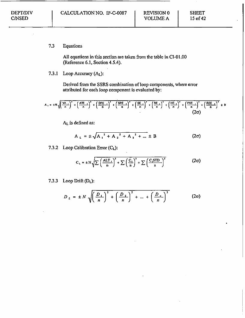
7.3 Equations
All equations in this section are taken from the table in CI-01.00(Reference 6.1, Section 4.5.4).
7.3.1 Loop Accuracy (AL):
Derived from the SSRS combination of loop components, where errorattributed for each loop component is evaluated by;
Al " NN |~( ) ((A ) + ( ). ( ,)' (SE,) (RE ,)' (HE ,)'+nnnnn n n
AL is defined as:
AL = ± JA 2 + A2 + A 2 + ± B
7.3.2 Loop Calibration Error (CL):
CL = ±NI(ALT STD
7.3.3 Loop Drift (DL):
\(n ) (n )(n)
( PEU V (REEEIV±n J ( n )
(2cr)
(2cr)
(2c)
(2cr)
DEPT/DIV CALCULATION NO. IP-C-0087 REVISION 0 SHEETC/NSED VOLUME A 16 of 42
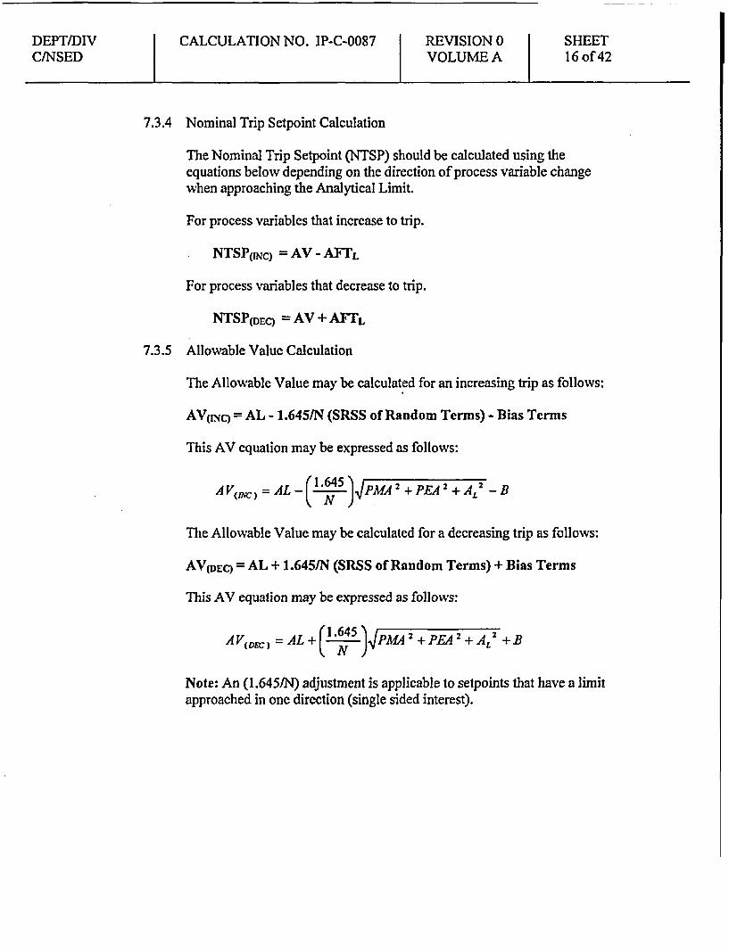
7.3.4 Nominal Trip Setpoint Calculation
The Nominal Trip Setpoint (NTSP) should be calculated using theequations below depending on the direction of process variable changewhen approaching the Analytical Limit.
For process variables that increase to trip.
NTSP(INc) =AV - AFTL
For process variables that decrease to trip.
NTSP(DEc) = AV + AFTL
7.3.5 Allowable Value Calculation
The Allowable Value may be calculated for an increasing trip as follows:
AV(INC) = AL - 1.645/N (SRSS of Random Terms) - Bias Terms
This AV equation may be expressed as follows:
A V' AL- ( 1645 )FPAM 2 + PA 2 +A 2 -BCN)The Allowable Value may be calculated for a decreasing trip as follows:
AV(DEC) = AL + 1.645/N (SRSS of Random Terms) + Bias Terms
This AV equation may be expressed as follows:
A (D) =AL + 4(l5 ) PM 2 + PE 2 + i 2 + B
Note: An (1.6451N) adjustment is applicable to setpoints that have a limitapproached in one direction (single sided interest).
DEPT/DIV CALCULATION NO. IP-C-0087 REVISION 0 SHEETCINSED VOLUME A 17 of 42
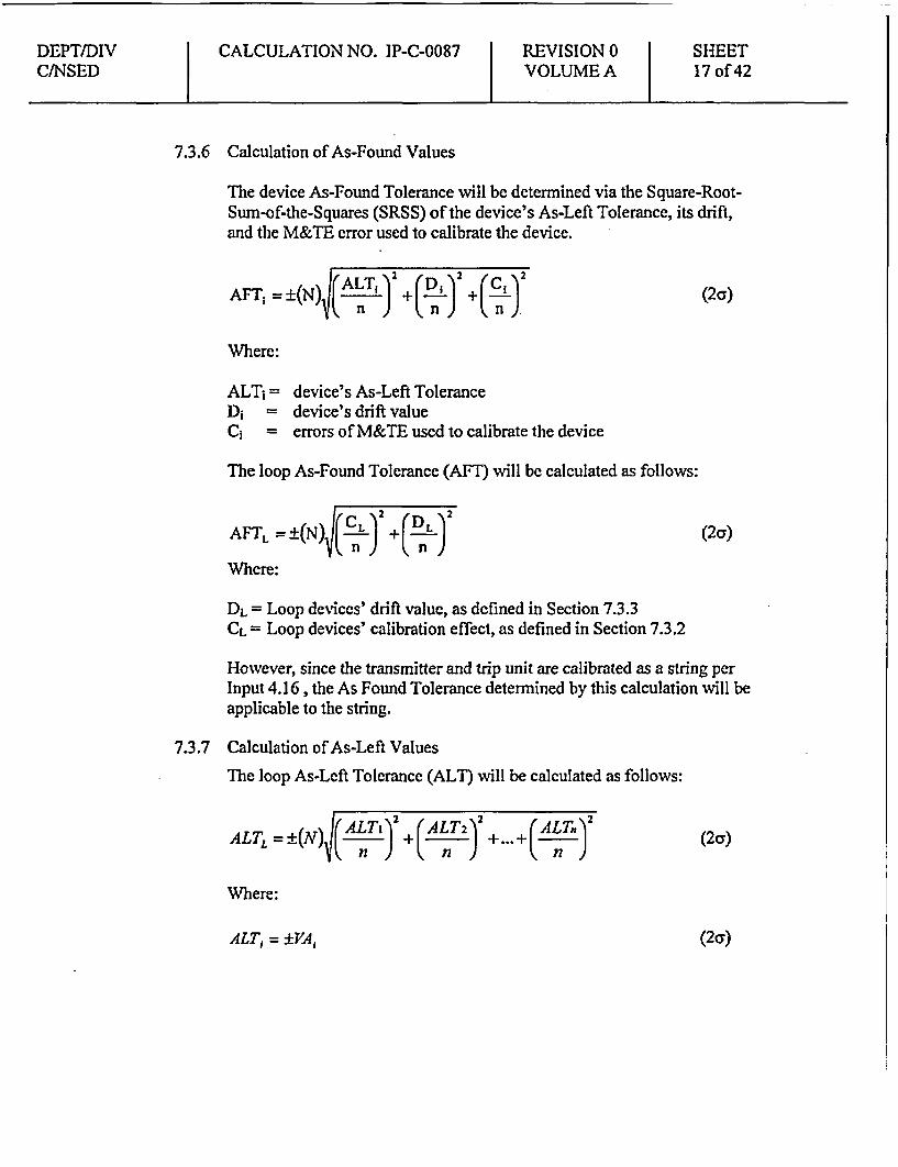
7.3.6 Calculation of As-Found Values
The device As-Found Tolerance will be determined via the Square-Root-Sum-of-the-Squares (SRSS) of the device's As-Left Tolerance, its drift,and the M&TE error used to calibrate the device.
AFT; =±(N) I( n-J +( PL) +( ) (2a)
Where:
ALTi = device's As-Left ToleranceDi =device's drift valueC; errors of M&TE used to calibrate the device
The loop As-Found Tolerance (AFT) will be calculated as follows:
AF *N)ICL ) (DL )2(aAFTL = ±:(N (C) (2oJ
Where:
DL = Loop devices' drift value, as defined in Section 7.3.3CL = Loop devices' calibration effect, as defined in Section 7.3.2
However, since the transmitter and trip unit are calibrated as a string perInput 4.16, the As Found Tolerance determined by this calculation will beapplicable to the string.
7.3.7 Calculation of As-Left Values
The loop As-Left Tolerance (ALT) will be calculated as follows:
ALTL = ±(N(LI)+(LT2) +.(A nJ(2ay)n n en
Where:
ALT, = ±V+A, (2a)

DEPTIDIV CALCULATION NO. [P-C-0087 REVISION 0 SHEETC/NSED VOLUME A 18 of 42
7.4 Determination of Uncertainties
7.4.1 Gould PD-3218 Differential Pressure Transmitters;* From Input 4.15, EIN lE22N055 (C & G) are Gould PD-3218-100-38-
12-10-5640 transmitters.* From Input 4.2.1, Vendor Accuracy = ±0.25% of Span* From Attachments 1, the transmitters are calibrated over a span of
125.5 to 155.5 inches of water column, or 30 inwc* From Input 4.2.1 the Upper Range Limit (URL) for the transmitters =
100 inwc* Per Assumption 2.1, all values are 2a.
7.4.1.1 Vendor Accuracy of pressure transmitters (VApT) - Per Input 4.2.1,Vendor Accuracy is ±0.25% of calibrated Span. Therefore:
VApr= ± 0.2500% Span (2a)
7.4.1.2 Accuracy Temperature Effect (ATEpT)
7.4.1.2.1 Normal Accuracy Temperature Effect (ATEpT(NOI.II.)) - Per Input4.2.1, the ATE is given as ±1.5% URL/200 IF between 40° to 250'F atmax span and ±5.0% URL/200IF between 400 to 250IF at min span.Per Input 4.3.1 and Section 7.2, the maximum Delta T equals 39 0F(104'-650F) under normal conditions. Therefore:
ATEp.JorNaj)= ± (1.5% URL)*(39 0/200 OF)*(l00 inwc/30 inwc)ATEpTr(ormai)= ± 0.9750% Span
ATEpT(NormaQ = ±0.9750% Span (2cr)
7.4.1.2.2 Accident Accuracy Temperature Effect (ATEPT(Accid)) - PerAssumptions 2.11 and 2.12, these instrument loops are not required tobe accurate in a post LOCA environment. Therefore:
ATEPT(Accid) = ATEpT(Normal)
ATEPT(Accid) = ±0.9750% Span
7.4.1.3 Humidity Effect (HEpT) - The vendor does not provide anyspecification for this effect (Input 4.2.1). Therefore, per Assumption2.3, Humidity Effects are negligible. Therefore:
HEpT= 0
DEPT/DIV CALCULATION NO. IP-C-0087 REVISION 0 SHEETC/NSED VOLUME A 19 of 42
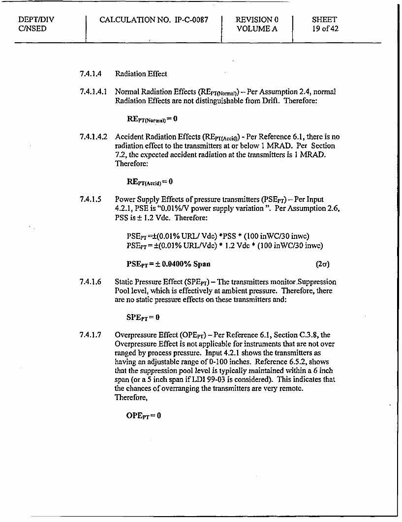
7.4.1.4 Radiation Effect
7.4.1.4.1 Normal Radiation Effects (REpT NormlaI)) - Per Assumption 2.4, normalRadiation Effects are not distinguishable from Drift. Therefore:
REpT(Normal) 0 °
7.4.1.4.2 Accident Radiation Effects (REPT(A~ccd) - Per Reference 6.1, there is noradiation effect to the transmitters at or below 1 MRAD. Per Section7.2, the expected accident radiation at the transmitters is 1 MRAD.Therefore:
REPr(ACcid) = 0
7.4.1.5 Power Supply Effects of pressure transmitters (PSEpr) - Per Input4.2.1, PSE is "0.010/o/V power supply variation ". Per Assumption 2.6,PSS is ± 1.2 Vdc. Therefore:
PSEpT±(0.01% URL/Vdc) *HSS * (100 inWC/30 inwc)PSEpT =±(0.01% URL/Vdc) * 1.2 Vdc * (100 inWC/30 inwc)
PSEPT= ± 0.0400% Span (2a)
7.4.1.6 Static Pressure Effect (SPEyr) -The transmitters monitor.SuppressionPool level, which is effectively at ambient pressure. Therefore, thereare no static pressure effects on these transmitters and:
SPEpT = 0
7.4.1.7 Overpressure Effect (OPEpr) -Per Reference 6.1, Section C.3.8, theOverpressure Effect is not applicable for instruments that are not overranged by process pressure. Input 4.2.1 shows the transmitters ashaving an adjustable range of 0-100 inches. Reference 6.5.2, showsthat the suppression pool level is typically maintained within a 6 inchspan (or a 5 inch span if LDI 99-03 is considered). This indicates thatthe chances of overranging the transmitters are very remote.Therefore,
OPEpT= 0

DEPT/DIV CALCULATION NO. IP-C-0087 REVISION 0 SHEETC/NSED VOLUME A 20 of 42
7.4.1.8 Seismic Effect
7.4.1.8.1 Normal Seismic Effect (SEpTraNOiuk) - Seismic activity is notconsidered when determining instrument uncertainty under normalconditions.
SEPT(ormal) =0
7.4.1.8.2 Accident Seismic Effect (SEpTr(Accid)) - Per Assumption 2.11, SeismicEffect is not considered to occur concurrent with a postulated LOCAevent.
SEPr(Accid) = 0
7.4.1.8.3 OBE/SSE Seismic Effect (SEprr(Scisjscl)) - Perlnput 4.2.1, SeismicEffect is ± 0.5% URL. Per Section 7.4.1 above, URL is 100 inwc andcalibrated span is 30 inwc. Therefore:
SEpT(scsni~c) = ± (0.5% URL) * (100 inwc/ 30 inwc)
SEpT(sjmic) = ± (0.5%) * 3.33
SEPT (Seismic)= ± 1.6667% Span (2a)
7.4.1.9 RFI/EMI Effect (REEPT) - Per Assumption 2.10, the effects ofRFIIEMI are considered negligible.
REEpr= 0
7.4.1.10 Bias (BpT) - From Appendix C of Reference 6.1, Bias is defined as asystematic or fixed instrument uncertainty that is predictable for agiven set of conditions because of the existence of a known direction(positive or negative). There are no identified bias effects for thistransmitter.
Therefore:
BPT = °
DEPT/DIVC/NSED
CALCULATION NO. IP-C-0087 REVISION 0VOLUME A
SHEET21 of 42
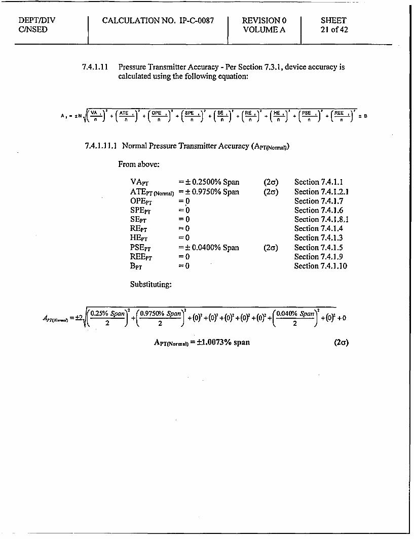
7.4.1.11 Pressure Transmitter Accuracy - Per Section 7.3.1, device accuracy iscalculated using the following equation:
V n ) ( ' + (ATE a(OPE ) a n ) ( ( n) (a) n ) (Hn E) _ (REE ')I_ B
7.4.1.1 1.1 Normal Pressure Transmitter Accuracy (ApTrNofnan))
From above:
VAPrATEPT (Nonmal)OPEprSPEPTSEpT
REPTHEPTPSEPTREEPTBPT
= + 0.2500% Span= ± 0.9750% Span=0=0=0=0=0= ± 0.0400% Span=0=0
(2a) Section 7.4.1.1(2a) Section 7.4.1.2.1
Section 7.4.1.7Section 7.4.1.6Section 7.4.1.8.1Section 7.4.1.4Section 7.4.1.3
(2a) Section 7.4.1.5Section 7.4.1.9Section 7.4.1.10
Substituting:
= ±2(0.2% SPan)2 2(09750°/ SPan) + +(Oy +(Oo +(O )2 +(OY +(O2 +(°S +(OY +0
APT(NormaI) = ±1.0073% span (2cr)
DEPT/DIVC/NSED
CALCULATION NO. IP-C-0087 REVISION 0VOLUME A
SHEET22 of 42
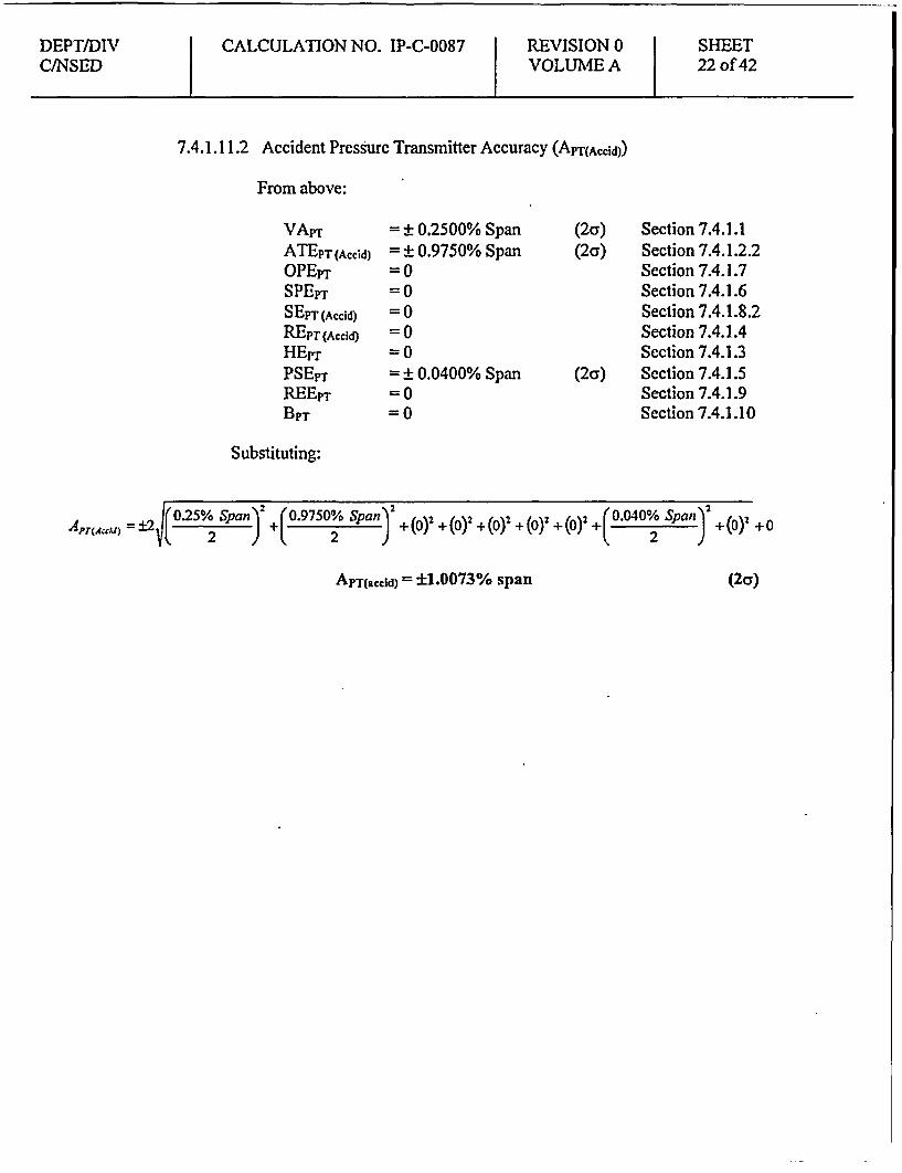
7.4.1.11.2 Accident Pressurc Transmitter Accuracy (APT(ACCid))
From above:
VAPrATEPT (Accid)OPEpTSPErTSEPT (Accid)
REPT (Accd)HEpTPSEpTREEPTBPT
= ± 0.2500% Span= ± 0.9750% Span=0=0=0=0=0= ± 0.0400% Span=0=0
(2a) Section 7.4.1.1(2a) Section 7.4.1.2.2
Section 7.4.1.7Section 7.4.1.6Section 7.4.1.8.2Section 7.4.1.4Section 7.4.1.3
(2a) Section 7.4.1.5Section 7.4.1.9Section 7.4.1.10
Substituting:
PT(Accd = a2 +(0.9750% Span)2 +(o)2 +(O)2 +(O)2 +(0) +(0)2 +L( 0 20 Span )+() +0
ApT(accid) = ±1.0073% span (2a)

DEPT/DIVC/NSED
CALCULATION NO. IP-C-0087 REVISION 0VOLUME A
SHEET23 of 42
7.4.1.11.3 Seismic Pressure Transmitter Accuracy (ApT(Scjsmic))
From above:
VApTATEPT (Normal)OPEPTSPEpTSEPT (Seismic)REprHEpT
PSEpTREErrBpT
= ± 0.2500% Span= ± 0.9750% Span=0=0= ± 1.6667% Span=0=0= ± 0.0400% Span=0=0
(2c) Section 7.4.1.1(26) Section 7.4.1.2.1
Section 7.4.1.7Section 7.4.1.6
(2c) Section 7.4.1.8.3Section 7.4.1.4Section 7.4.1.3
(2c) Section 7.4.1.5Section 7.4.1.9Section 7.4.1.10
Substituting:
± 25 Span)2 +(o.975/O Span) +(o)2 +(o +(1 .666716span) +(0)4+(o)2+ SPan) +2()2 +0
Arpr(sdsmc) = ±1.9475% span (2cr)
7.4.1.11.4 Pressure Transmitter Accuracy (APT)
Based on the above, the largest uncertainty is expected under seismicconditions. Therefore:
APT
APT
= APT(Seismic)
= ± 1.9475. % Span (2cr)
7.4.2 Suppression Pool Level High Analog Trip Module (ATM)1E22N655 (C & G).
* Per Input 4.4.13 & 4.8.5, EINs IE22N655 (C & G) are GE AnalogTrip Modules, Model Number 147D8505G005 (147D8505G006alternate).
* Per Input 4.8.4, the input range for the ATM is 4-20 mA.* Per Input 4.8.4, the vendor accuracy is ±0.25% Full Scale (Span).* Per Section 7.2, ATM's are located in a mild environment and
therefore Accident Conditions will not need to be considered.

DEPT/DIV CALCULATION NO. IP-C-0087 REVISION 0 SHEEC/NSED VOLUME A 24 of 42
7.4.2.1 Vendor Accuracy (VAATM) - Per Input 4.8.4, the vendor accuracy is±0.25% Span. Therefore:
VAATNM = ±0.2500% Span (2cr)
7.4.2.2 Accuracy Temperature Effect (ATEATM) - The vendor does notprovide any specification for this effect (Input 4.8.4). Therefore, perAssumption 2.2, the Accuracy Temperature Effect is considered to beincluded in the vendor accuracy.
ATEATht = 0
7.4.2.3 Overpressure Pressure Effect (OPEA-m) - OPE is not applicable toAnalog Trip Modules.
OPEATNI = 0
7.4.2.4 Static Pressure Effect (SPEATM) - SPE is not applicable to Analog TripModules.
SPEADIl = 0
7.4.2.5 Seismic Effect (SEATM) - Analog Trip Modules have been seismicallyqualified using the manufactures published accuracy requirements(Input 4.7.2). Based on a review of Input 4.7.2, there is no additionalerror considerations which must be considered for seismic conditions.Therefore:
SEAD = 0
7.4.2.6 Radiation Effect (REA-l) -The 1E22N655 (C & G) ATMs are locatedin a mild enviroment, and therefore, not subject to any significantradiation exposure. Therefore, the Radiation Effect is considerednegligible.
REATM = °
7.4.2.7 Humidity Efffect (HEATM) - The vendor does not provide anyspecification for this effect (Input 4.8.4). Therefore, per Assumption2.2, the Humidity Effect is considered to be included in the VendorAccuracy.
HEATM -0

DEPT/DIVC/NSED
CALCULATION NO. IP-C-0087 REVISION 0VOLUME A
SHEET25 of 42
7.4.2.8 Power Supply Effect (PSEATM) - The vendor does not provide anyspecification for this cffect (Input 4.8.4). Therefore, per Assumption2.2, the Power Supply Effect is considered to be included in theVendor Accuracy.
PSEATMN= 0
7.4.2.9 RFI/EMI Effect (REEATM) - Per Assumption 2.10, the effects ofRFIIEMI are considered negligible.
REEATNI = 0
7.4.2.10 Bias (BAD,{) - From Appendix C of Reference 6.1, Bias is defined as asystematic or fixed instrument uncertainty that is predictable for agiven set of conditions because of the existence of a known direction(positive or negative). No such error was identified for the ATMsused for measurement of Suppression Pool Level - High. Therefore:
BATMI = 0
7.4.2.11 From Section 7.3.1, AATM is calculated by:
VA, + (ATE )2 + (OPEl )2 + (SPE)2+ (SE, )2
From above:
+ (RE,)' + (HE, (PEE + (REE 1 )2
_n) +(n) JREn ±
VAATM
ATEATMOPEATM
SPEATM:SEAThMREATMHEATMPSEATWREEAmqBATM
Substituting:
= ± 0.2500% Span=0=0=0=0=0=0=0=0=0
(2cr) Section 7.4.2.1Section 7.4.2.2Section 7.4.2.3Section 7.4.2.4Section 7.4.2.5Section 7.4.2.6Section 7.4.2.7Section 7.4.2.8Section 7.4.2.9Section 7.4.2. 10
I(0.25% Span) +(by + (or + (oy + (o + (b) + (O) + (0) + (o +0
AATM = ± 0.2500% span (2ay)
DEPT/DIVCJNSED
CALCULATION NO. IP-C-0087 REVISION 0VOLUME A
SHEET26 of 42
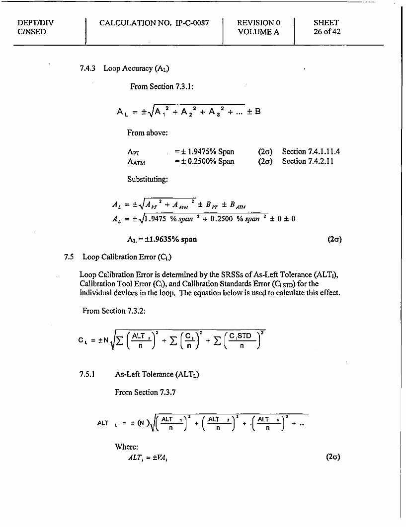
7.4.3 Loop Accuracy (AL)
From Section 7.3. 1:
AL = +VA, 2 + A22 + A3
2 + ... ± B
From above:
APTAATM
= ± 1.9475% Span= ± 0.2500% Span
(2a)(2a)
Section 7.4.1.11.4Section 7.4.2.11
Substituting:
AL = ±jA,7 2 + AATM 2 Bp7 ± BAv
AL = ±11.9475 % span 2 + 0.2500 %span 2 ± 0 ± 0
AL = ±1.9635% span (2cr)
7.5 Loop Calibration Error (CL)
Loop Calibration Error is determined by the SRSSs of As-Left Tolerance (ALT;),Calibration Tool Error (C;), and Calibration Standards Error (C1 sTD) for theindividual devices in the loop. The equation below is used to calculate this effect.
From Section 7.3.2:
'2
CL = ±N(ALT ,1
n )!+z E C, 2 E C ISTD )2
7.5.1 As-Left Tolerance (ALTL)
From Section 7.3.7
ALT L = ± (N )J( ALT I ) +
Where:ALT, = ±VA,
(ALT 22 + ( ALT ) 2+n n
(2cr)

DEPT/DIV CALCULATION NO. IP-C-0087 RE-VISION 0 SHEETCJNSED VOLUME A 27 of 42
Determining the ALT for the transmitter (ALTp'r),
ALTpT = ± VAyr
ALTPT = ±0.2500% span (2a)
Transmitter As Found / As Left limits are stated in Vdc per Input 4.1.Converting to Vdc at a precision of 0.001 Vdc
ALTp = ±0.2500 %span * ((5 - 1)Vdc)span
ALTPT = ± 0.010 Vdc (2a)
Determining the ALT for the Analog Trip Unit (ALTAW),
ALTATM = + VAATMALTATM = ±0.2500% span (2a)
ATM As Found / As Left limits are stated in IN WATER per Input4.16 at a precision of 0.01 IN WATER.
Converting to IN WATER
ALTA4hI = ±0.2500%span * (+15 - (-15)J]V _WATER )span
= ±0.0750 IWATERPer Input 4.16 the ALT is 0.30 inwc nonsymmetrical or 0.15 inwc.Using the larger of the two values;
ALTATq = ± 0.15 IN WATER (2cr)
Converting to % span
ALTA,7x, = ±[0.151N _WATER I(+15 -(-15)INWATER)span]*100%span
= ±0.5%spanTherefore
ALTATM = +0.5% span (2cy)

DEPT/DIV CALCULATION NO. IP-C-0087 REVISION 0 SHEETCINSED VOLUME A 28 of 42
Determining the ALT for the loop (ALTL),
ALTL =±(N) AL(rr) +(ALTANj
ALTL = 0 2 50 0 %Span 2 + (0.5%Span )
ALTL = + 0.5590% Span (2a)
Loop As Found / As Left limits are stated in IN WATER per Input4.16 at a precision of 0.01 IN WATER.
Converting to IN WATER
ALT, = ±0.5590%span * (+15 - (-15)IN A WATER )span
= ±0.161N _WATER (rounded down)Per Input 4.16 the ALT is 0.29 inwe nonsymmetrical or 0.145 inwc.Using the larger of the two values;
ALTL = ± 0.16 IN WATER (2a)
Converting to % span
ALTL = ±[0.16IN _WATER I(+15 - (-15)I _NWATER)span]* 100%span
= +0.5333 %spanTherefore
ALTL = ±0.5333% span (2a)
7.5.2 Calibration Tool Error (CQ)
7.5.2.1 Transmitter Calibration Tool Error (CpT)
The loop is calibrated with a DC voltmeter that is capable ofmeasuring 1-5 Vdc (currently specified as a Fluke 45) and a test gaugerange of 0-200 inwc. A 250 ohm precision resistor is required,accurate to ±0.02 ohms. This information is from Section 7.0 of Input4.16. A review of Calculation IP-C-0089 (Input 4.6.1) did not identifya test gauge with a 200 inwc range.
Per review of completed surveillance, the test gauge used for thecalibration is a Heise 901 B digital indicator with a range of 0-1 60 inwe
DEPT/DIV CALCULATION NO. IP-C-0087 REVISION 0 SHEETC/NSED VOLUME A 29 of 42
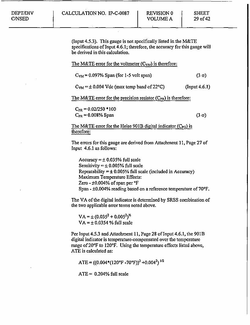
(Input 4.5.3). This gauge is not specifically listed in the M&TEspecifications of Input 4.6.1; therefore, the accuracy for this gauge willbe derived in this calculation.
The M&TE error for the voltmeter (CVM) is therefore:
CVM= 0.097% Span (for 1-5 volt span) (3 cr)
CVM = ± 0.004 Vdc (max temp band of 221C) (Input 4.6.1)
The M&TE error for the precision resistor (CpR) is therefore:
CPR = 0.02/250 *100CPR = 0.008% Span (3 cr)
The M&TE error for the Heise 901 B digital indicator (CpG) istherefore:
The errors for this gauge are derived from Attachment 1 1, Page 27 ofInput 4.6.1 as follows:
Accuracy = ± 0.035% full scaleSensitivity = ± 0.005% full scaleRepeatability = ± 0.005% full scale (included in Accuracy)Maximum Temperature Effects:Zero - ±0.004% of span per IFSpan - ±0.004% reading based on a reference temperature of 70'F.
The VA of the digital indicator is determined by SRSS combination ofthe two applicable error terms noted above.
VA = ± (0.0352 + 0.0052)V2VA = ± 0.0354 % full scale
Per Input 4.5.3 and Attachment 11, Page 28 of Input 4.6.1, the 901Bdigital indicator is temperature-compensated over the temperaturerange of 201F to 1200F. Using the temperature effects listed above,ATE is calculated as:
ATE = ((0.004*(1200 F -70oF))2 +0.0042) 1/2
ATE = 0.204% full scale
DEPT/DIV CALCULATION NO. IP-C-0087 REVISION 0 SHEETC/NSED VOLUME A 30 of 42
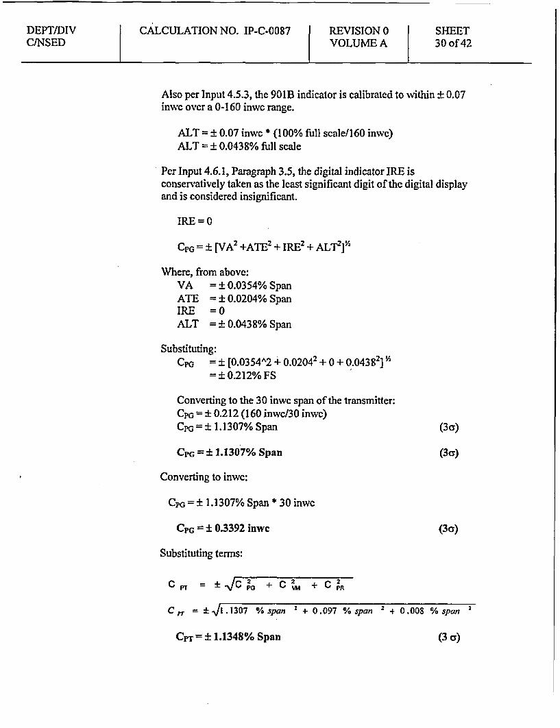
Also per Input 4.5.3, the 901B indicator is calibrated to within ± 0.07inwc over a 0-160 inwc range.
ALT = 0.07 inwc * (100% full scale/160 inwc)ALT = 0.0438% full scale
Per Input 4.6.1, Paragraph 3.5, the digital indicator IRE isconservatively taken as the least significant digit of the digital displayand is considered insignificant.
IRE =0
CPG = i [VA2 +ATE2 + IRE2 + ALT2f'
Where, from above:VA = ± 0.0354% SpanATE = ± 0.0204% SpanIRE =0ALT = ± 0.0438% Span
Substituting:CPG = ± [0.0354A2 + 0.02042 + 0 + 0.04382] ]A
= ± 0.212% FS
Converting to the 30 inwc span of the transmitter:CpG = ± 0.212 (160 inwc/30 inwc)CpG = ± 1.1307% Span (3q)
CPG = ± 1.1307% Span (3cy)
Converting to inwe:
CPG 1.1307% Span * 30 inwc
CPG = ± 0.3392 inwc (3Cy)
Substituting terms:
PT= iVC + C + C
CPT = 1 ]l.1307 % span 2 + 0.097 % span 2 + 0 .008 % span 2
CPT= ± 1.1348% Span (3 as)
DEPT/DIVCINSED
CALCULATION NO. IP-C-0087 REVISION 0VOLUME A
SHEET31 of 42
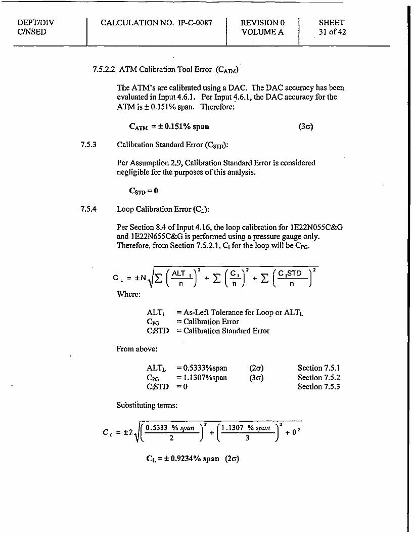
7.5.2.2 ATM Calibration Tool Error (CATM)
The ATM's are calibrated using a DAC. The DAC accuracy has beenevaluated in Input 4.6.1. Per Input 4.6.1, the DAC accuracy for theATM is ± 0.151% span. Therefore:
CATM = ± 0.151% span (3ca)
7.5.3 Calibration Standard Error (Csnm):
Per Assumption 2.9, Calibration Standard Error is considerednegligible for the purposes of this analysis.
Loop Calibration Error (CL):7.5.4
Per Section 8.4 of Input 4.16, the loop calibration for IE22N055C&Gand I E22N655C&G is performed using a pressure gauge only.Therefore, from Section 7.5.2.1, C; for the loop will be CpG.
CL = ±N |
Where:
CALT J2
( n + z ( n) + 2:(CISTD2)
ALT1CP&
CiSTD
= As-Left Tolerance for Loop or ALTL= Calibration Error= Calibration Standard Error
From above:
ALTLCPG
CSTD
= 0.5333%span= I.1307%span=0
(2c)(3cr)
Section 7.5.1Section 7.5.2Section 7.5.3
Substituting terms:
CL05333 span ) 2 + (1.1307 ; span )2+02
CL = ± 0.9234% span (2a)

DEPT/DIV CALCULATION NO. IP-C-0087 REVISION 0 SHEETC/NSED VOLUME A 32 of 42
7.6 Loop Drift
7.6.1 Pressure Transmitter Drift (DPr):
Per Input 4.2.1, Drift is ±0.25% URL for 6 months, and per Reference 6.1it is considered a 2cr value. Drift will be determined based on a nominal30-month calibration interval (Assumption 2.7), in accordance withTechnical Specifications allowance for the surveillance for up to 1.25% ofthe required interval, or 30 months (24*1.25=30). Section 7.4.1 shows thecalibrated span as 30 inwc and the URL as 100 inwc. Therefore perReference 6.1:
DPr = (30 mo/6 mo)"'2 (± 0.25% URL) (100 inwc/30 inwc)
DPT = ±1.8634% Span (2cy)
7.6.2 Analog Trip Module Drift (DATM):Per Input 4.8.4, Drift is ±0.25% of Span for a period of 30 days. Per thecalibration procedure (Input 4.17), the calibration frequency is 92 days.Technical Specifications allow for the surveillance to be delayed for up to1.25% of the required interval, or 115 days (92*1.25=115). Therefore, perRef. 6.1:
DATM = ±0.25% * (115 days/30 days)'
DATM = ±0.4895% Span (2ca)
7.6.3 Loop Drift (DL):From Section 7.3.3, Loop Drift is calculated:
D i.=±N_)IJ( L + ... + 2i-
DL n ) 8 s n ) + n
tD. 2 VA( 1. 8634 % span ) 2+( 0.4895 % span )2
DL = ±1.9266% Span (2cr)
DEPT/DIV CALCULATION NO. IP-C-0087 REVISION 0 SHEETC/NSED VOLUME A 33 of 42
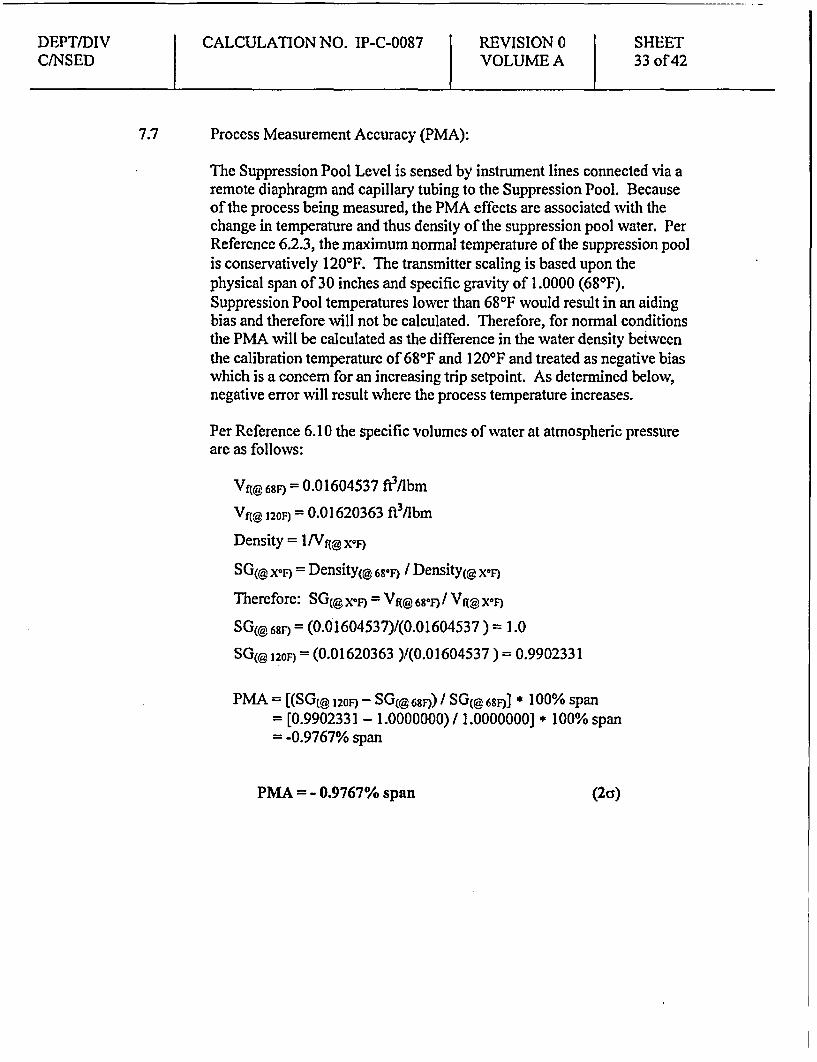
7.7 Process Measurement Accuracy (PMA):
The Suppression Pool Level is sensed by instrument lines connected via aremote diaphragm and capillary tubing to the Suppression Pool. Becauseof the process being measured, the PMA effects are associated with thechange in temperature and thus density of the suppression pool water. PerReference 6.2.3, the maximum normal temperature of the suppression poolis conservatively 1201F. The transmitter scaling is based upon thephysical span of 30 inches and specific gravity of 1.0000 (681F).Suppression Pool temperatures lower than 681F would result in an aidingbias and therefore will not be calculated. Therefore, for normal conditionsthe PMA will be calculated as the difference in the water density betweenthe calibration temperature of 681F and 1200F and treated as negative biaswhich is a concern for an increasing trip setpoint. As determined below,negative error will result where the process temperature increases.
Per Reference 6.10 the specific volumes of water at atmospheric pressureare as follows:
VA 68F) = 0.01604537 ft3 /lbm
Vf( 120F) = 0.01620363 ft3Abm
Density = I Nlf x
SG(@ xoi9 = Density 0 6s8° / Density(@ X0F)
Therefore: SG( x°F) = Vf( 6S8F) / V 0X°F)
SG(@68F) = (0.01604537)/(0.01604537 ) = 1.0
SG(@ 120F = (0.01620363 )/(0.01604537 ) = 0.9902331
PMA = [(SG(@ 120 - SG(@ 6S) / SG(@ 68s * 100% span= [0.9902331 - 1.0000000) / 1.0000000] * 100% span= -0.9767% span
PMA = - 0.9767% span (2as)
DEPT/DIV CALCULATION NO. IP-C-0087 REVISION 0 SHEETC/NSED VOLUME A 34 of 42
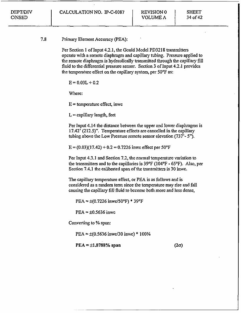
7.8 Primary Element Accuracy (PEA):
Per Section 1 of Input 4.2.1, the Gould Model PD3218 transmittersoperate with a remote diaphragm and capillary tubing. Pressure applied tothe remote diaphragm is hydraulically transmitted through the capillary fillfluid to the differential pressure sensor. Section 3 of Input 4.2..1 providesthe temperature effect on the capillary system, per 50'F as:
E = 0.03L + 0.2
Where:
E = temperature effect, inwc
L = capillary length, feet
Per Input 4.14 the distance between the upper and lower diaphragms is17.42' (212.5)". Temperature effects are cancelled in the capillarytubing above the Low Pressure remote sensor elevation (737'- 5').
E = (0.03)(17.42) + 0.2 = 0.7226 inwc effect per 500F
Per Input 4.3.1 and Section 7.2, the normal temperature variation tothe transmitters and to the capillaries is 39WF (104'F - 650F). Also, perSection 7.4.1 the calibrated span of the transmitters is 30 inwc.
The capillary temperature effect, or PEA is as follows and isconsidered as a random term since the temperature may rise and fallcausing the capillary fill fluid to become both more and less dense,
PEA = ±(0.7226 inwc/501F) * 391F
PEA = ±0.5636 inwc
Converting to % span:
PEA = ±(0.5636 inwc/30 inwc) * 100%
PEA = ±1.8788% span (2cy)

DEPT/DIVCINSED
CALCULATION NO. IP-C-0087 REVISION 0VOLUME A
SHEET35 of 42
8.0 RESULTS
8.1 Calculation of the Allowable Value (AV)
From Input 4.9, the Analytical Limit (AL) is 1 foot above instrumentnominal trip setpoint, pool high level (increasing).
The Allowable Value may be calculated for an increasing trip as follows:
AV = AL - 1.6451N (SRSS of Random Terms) - Bias Terms
This AV equation may be expressed as follows by utilizing the randomterms defined in Section 4.5.2.1 of Ref. 6.1:
AV = AL - 1.645 +PA ,AV=AL(l.N )'IPMA2 +PEA2+AL2 ±B
Note that the random and bias terms are defined in Section 4.5.2 of Ref.6.1. TMe calculation of the AV does not include the CL and DL terms.
Where:
ALLo,=Calibrated SpanPMA
PEA
AL
B
= 12 inwc-30 inwc- ±0% Span (2a)
± 0% Span * 30 inwc=±0.0 inwc= 1.8788 % Span (2a)= 1.8788% Span * 30 inwc=10.5636 inwc=i1.9635% Span (2c)= 1.9635% Span * 30 inwc-i0.5891 inwc= -0.9767% Span= -0.9767% Span * 30 inwc= -0.2930 inwc=2
Section 8.2Section 7.4.1Section 7.7.2
Section 7.8.2
Section 7.4.3
Section 7.7
N Section 7.3

DEPT/DIV CALCULATION NO. IP-C-0087 REVISION 0 SHEETC/NSED VOLUME A 36 of 42
Substituting:
AV = AL ( )IPMA2 +PEA2+AL2 ±B
AV = 12inivc - (1 J 2 0 2 + 0.5636 inwc 2 + 0.5891 inVc 2 - 0.2930 inivc
AV • 11.0364 inwe above pool high level
CPS Technical Specification (Reference 6.5.1) Table 3.3.5.1-1 (Item 3.e),lists the Allowable Value as < 12 inches, which is referenced from aninstrument zero corresponding to 731 '-5" (per the Bases of these TechSpecs). Per Input 4.10, the Analytical Limit of 1 foot above pool highlevel (731 '-5") corresponds to 732'-5". The existing Allowable Value of• 12 inches from instrument zero of 731 '-5" is 732'-5" and corresponds tothe 732'-5" (or 1 foot above pool high level) recently provided by GE asthe Analytical Limit. Therefore the existing Allowable Value is non-conservative. Using the 5 11.0 inches above pool high level (731 '-5")corresponds to • 732'4 inches for the newly calculated Allowable Value.LDI 99-02 lowered the value in the Tech Spec from < 12 inches to < 8.5,however, AV will be changed with the results of this calculation to • 11.0inches.
AV 11.0 inches (referenced from 731'-5") (2 a)
8.2 Calculation of the Trip setpoint:
From Input 4.9, the Analytical Limit (AL) is 1 foot above instrumentnominal trip setpoint, pool high level (increasing).
The Nominal Trip Setpoint (NTSP) is calculated using the equation belowfor process variables that increase to trip.
NTSP = AV - AFTL
Where:
AV = 11.0 inwc Section 8.2AFTL = 0.64 inwe Section 8.3.3
Therefore, the trip setpoint (NTSP) is:
NTSP = AV - AFTL
DEPT/DIV CALCULATION NO. IP-C-0087 REVISION 0 SHEETC/NSED VOLUME A 37 of 42
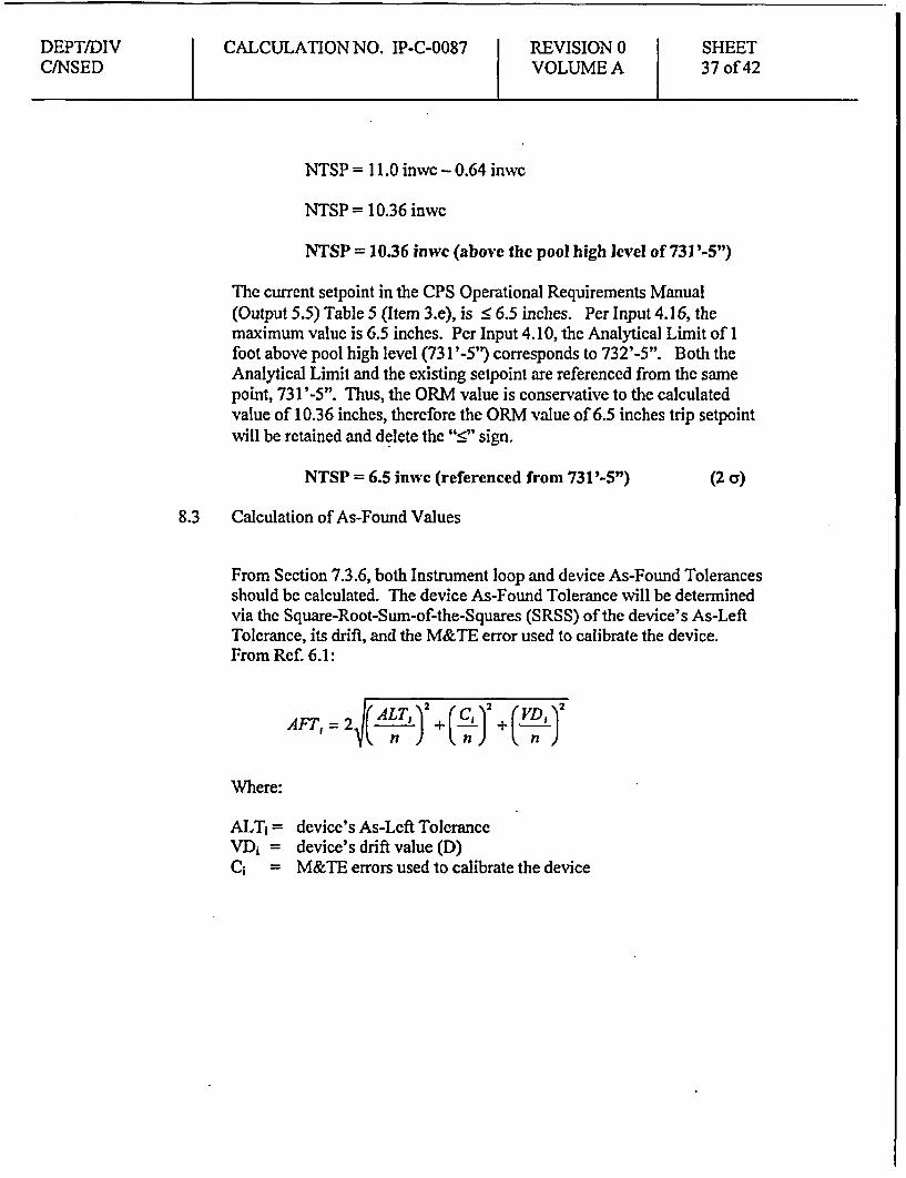
NTSP = 11.0 inwe - 0.64 inwc
NTSP = 10.36 inwc
NTSP = 10.36 inwc (above the pool high level of 731'-5")
The current setpoint in the CPS Operational Requirements Manual(Output 5.5) Table 5 (Item 3.e), is < 6.5 inches. Per Input 4.16, themaximum value is 6.5 inches. Per Input 4. 10, the Analytical Limit of 1foot above pool high level (731'-5') corresponds to 732'-5". Both theAnalytical Limit and the existing setpoint are referenced from the samepoint, 731 '-5". Thus, the ORM value is conservative to the calculatedvalue of 10.36 inches, therefore the ORM value of 6.5 inches trip setpointwill be retained and delete the "•" sign.
NTSP = 6.5 inwc (referenced from 731'-5") (2 c)
8.3 Calculation of As-Found Values
From Section 7.3.6, both Instrument loop and device As-Found Tolerancesshould be calculated. The device As-Found Tolerance will be determinedvia the Square-Root-Sum-of-the-Squares (SRSS) of the device's As-LeftTolerance, its drift, and the M&TE error used to calibrate the device.From Ref. 6.1:
AFT, = 15/(ALT' +2(2L +(a , )
Where:
ALTi = device's As-Left ToleranceVDi = device's drift value (D)C; = M&TE errors used to calibrate the device

DEPT/DIVC/NSED
CALCULATION NO. IP-C-0087 REVISION 0VOLUME A
SHEET38 of 42
8.3.1 Calculating As-Found Tolerance (AFTPT) for transmitters IE22-N055C(G):
From above:
Calibrated Span = 30 inwcALTpr = ± 0.2500% SpanDyr = ± 1.8634% spanCrr =± i1.1348% span
(2a)(2a)(3c)
Section 7.4.1Section 7.5.1Section 7.6.1Section 7.5.2
Substituting:
A~f =T ±2 1(ALTPn ) +2(c rn) +(2 2 1)
AE7r = ±2j|( 0.2500 /ospan 2 (1.8634 %span2
2 )+ (1.1348 %span )
AFT PT = +2.0266 %span
Transmitter As Found / As Left limits are stated in Vdc per Input 4.16.Converting to Vdc at a precision of 0.001 Vdc
AFTpzT = +2.0266 %span * ((5 - I)Vdc)span
= ±0.0811Vdc
Rounding (conservatively) to the precision of Input 4.16.
AFTPT = ± 0.081 Vdc (2af)
8.3.2 Calculating As-Found Tolerance (AFTAmr) forATMs lE22-N655(C&G)
From above:
Calibrated SpanALTATM
DATM
CATM
=30 inwc= ± 0.5% span= ± 0.4895% span=±0.151% span
(2c;)(2a)(3a)
Section 7.4.2Section 7.5.1Section 7.6.2Section 7.5.4

DEPT/DIVCINSED
CALCULATION NO. IP-C-0087 REVISION 0VOLUME A
SHEET39 of 42
Substituting:
A)AT = ±2j (CAM 2 2D )
AFAT = ±2 J(0.5%sPan )2+ (0.4895 /Ospan 2+ (0.151 %span ' 2
3)I
AFTlAn = ±0.7069 %span
ATM As Found / As Left limits are stated in IN WATER per Input4.16 at a precision of 0.01 IN WATER.
Converting to IN WATER
AFT,1w = ±0.7069%span * (+15 - (-15)IN _WATER )span
= ±0.2121 IN _W JATER
Rounding (conservatively) to match the precision of Input 4.16
AFTATm = ± 0.21 IN WATER (2a)
8.3.3 Loop As-Found Tolerance (AFTL) - From Section 7.3.8, the loop As-Found Tolerance (AFT) will be calculated as follows:
AFT L = ±F (N )A( C )
From above:
+ (DL )2
Calibrated Span = 30 inwcCL = ± 0.9234% SpanDL = ± 1.9266% Span
(2a)(2a)
Section 7.4.1Section 7.5.4Section 7.6.3
Substituting:
AFTL =± (N )C +
AFTL . 0 1 (*09234 %Ospan jAFTL =+2.1365 %span
1.9266 %;span 2
2

DEPT/DIV CALCULATION NO. IP-C-0087 REVISION 0 SHEETC/NSED VOLUME A 40 of 42
Loop As Found / As Left limits are stated in [N WATER per Input4.16 at a precision of 0.01 IN WATER.
Converting to IN WATER
AFTL =±2.1365%span * (+15 - (-15)IN _WATER )span
=± 0.6409 IN_ WATER
AFTL = ± 0.64 IN WATER (2c)
8.4 Calculation of Reset Value
The trip reset value is selected to prevent overlap with the acceptableNTSP tolerance band, and also to prevent interference with normal plantoperations. The maximum reset value is calculated as follows for theincreasing trip function:
Reset • NTSP - AFTL
Reset < (6.5 inwc) - 0.64 inwcReset • 5.86 inwc
From Input 4.16, the existing reset is 5.6 inwc which is 0.9 inwc below theexisting field setting (6.5 inwe). This is a difference of +3% span, whichequals the standard differential used for ATMs at CPS. The 0.9 inwcexisting differential is greater and therefore more conservative (movesprocess further away from AL) than the 0.64 inwc minimum resetdifferential derived from AFTL. Adding the 3% differential to the NTSPdetermines the reset value:
Reset = 6.5 inwe - 3% * 30 inwc span= 6.5 inwc - 0.9 inwc
Reset = 5.6 inches
DEPT/DIV CALCULATION NO. IP-C-0087 REVISION 0 SHEETC/NSED VOLUME A 41 of 42
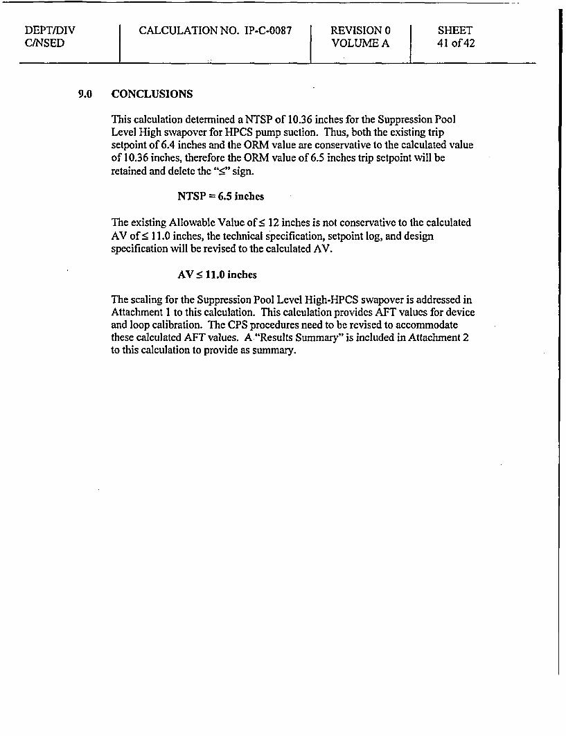
9.0 CONCLUSIONS
This calculation determined aNTSP of 10.36 inches for the Suppression PoolLevel High swapovcr for HPCS pump suction. Thus, both the existing tripsetpoint of 6.4 inches and the ORM value are conservative to the calculated valueof 10.36 inches, therefore the ORM value of 6.5 inches trip setpoint will beretained and delete the "•" sign.
NTSP = 6.5 inches
The existing Allowable Value of S 12 inches is not conservative to the calculatedAV of 5 11.0 inches, the technical specification, setpoint log, and designspecification will be revised to the calculated AV.
AV < 11.0 inches
The scaling for the Suppression Pool Level High-HPCS swapover is addressed inAttachment 1 to this calculation. This calculation provides AFT values for deviceand loop calibration. The CPS procedures need to be revised to accommodatethese calculated AFT values. A "Results Summary" is included in Attachment 2to this calculation to provide as summary.
DEPT/DIVCJNSED
CALCULATION NO. IP-C-0087 REVISION 0VOLUME A
SHEET42 of 42
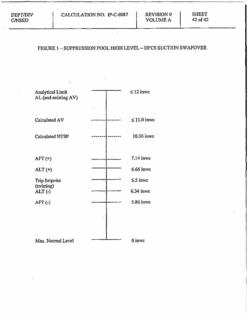
FIGURE 1 - SUPPRESSION POOL HIGH LEVEL - HPCS SUCTION SWAPOVER
Analytical LimitAL (and existing AV)
Calculated AV
Calculated NTSP
< 12 inwc
< 11.0 inwc
10.36 inwc
AFT (+)
ALT (+)
Trip Setpoint(existing)ALT (-)
AFT (-)
7.14 inwc
6.66 inwc
6.5 inwc
6.34 inwc
5.86 inwc
Max. Normal Level 0 inwc
DEPT/DIV CALCULATION NO. IP-C-0087 REVISION 0 SHEETCJNSED ATTACHMENT 1 VOLUME A I of 4
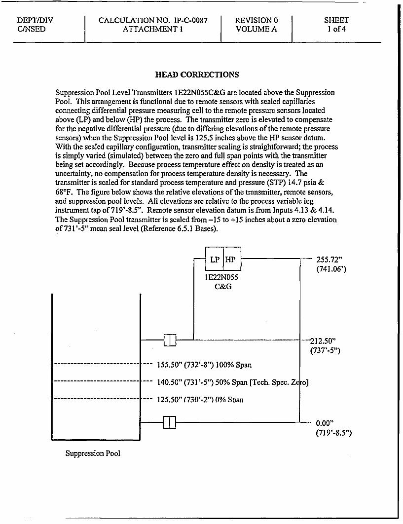
HEAD CORRECTIONS
Suppression Pool Level Transmitters IE22N055C&G are located above the SuppressionPool. This arrangement is functional due to remote sensors with sealed capillariesconnecting differential pressure measuring cell to the remote pressure sensors locatedabove (LP) and below (BP) the process. The transmitter zero is elevated to compensatefor the negative differential pressure (due to differing elevations of the remote pressuresensors) when the Suppression Pool level is 125.5 inches above the HP sensor datum.With the sealed capillary configuration, transmitter scaling is straightforward; the processis simply varied (simulated) between the zero and full span points with the transmitterbeing set accordingly. Because process temperature effect on density is treated as anuncertainty, no compensation for process temperature density is necessary. Thetransmitter is scaled for standard process temperature and pressure (STP) 14.7 psia &680F. The figure below shows the relative elevations of the transmitter, remote sensors,and suppression pool levels. All elevations arc relative to the process variable leginstrument tap of 719'-8.5". Remote sensor elevation datum is from Inputs 4.13 & 4.14.The Suppression Pool transmitter is scaled from -15 to +15 inches about a zero elevationof 731 '-5" mean seal level (Reference 6.5.1 Bases).
255.72"(741.06')
---212.50"(737'-5")
--- 155.50" (732'-8") 100% Span
- - - - 140.50" (731 '-5") 50% Span [Tech. Spec. Ze o]
---- 125.50" (730'-2") 0% SDan
--- 0.00"(719'-8.5")
Suppression Pool

DEPTIDIV CALCULATION NO. IP-C-0087 REVISION 0 SHEETC/NSED ATTACHMENT 1 VOLUME A 2 of 4
SCALING OF THE SUPPRESSION POOL LEVEL -HIGH (HPCS)SWAPOVER INSTRUMENT LOOP
1 Transmitters
]E22N055C & G
Manufacturer: GouldModel No.: PD3218Input: 125.50 to 155.50 inwcOutput: 1.000 - 5.000 Vdc
Process Range
Mn (p) Max (P) Units
p=125.50 P=155.50 inwc
Transmitter Output Range
Min(o) Max(O) Units
o=1.000 0=5.000 Vdc
As shown above, there are no head corrections necessary to apply to thetransmitters. Transmitter zero is elevated to 125.50". Any head effect due tochanges in temperature of the pool water have been incorporated into theinstrument uncertainty as PMA as discussed in Section 7.7 above. Thetransmitters are aligned to reflect from -15 inches to +15 inches of water with theinstrument zero referenced to the pool high level elevation of 731 '-5". Theinformation above shows that the minimum level of 125.50" corresponds from thecenterline of the bottom tap of the suppression pool (elevation 719'-8.5") to 15inches below (i.e., -15 inches) the pool high elevation of 731 '-5", which is 730'-2". Similarly, the maximum level of 155.50" corresponds from the bottom of thesuppression pool (elevation 719'-8.5') to 15 inches (i.e., +15 inches) above thepool high elevation of 731 '-5", which is 732'-8". The association between thepool levels, elevations, and equivalent output voltage is shown below:

DEPT/DIVCtNSED
CALCULATION NO. IP-C-0087ATTACHMENT I
REVISION 0VOLUME A
SHEET3 of4
Pool level
-15.00"
-7.50"
0.00"
+7.50"
+15.00"
Input
125.50 inwc
133.00 inwe
140.50 inwc
148.00 inwc
155.50 inwc
Output
1.000 Vdc
2.000 Vdc
3.000 Vdc
4.000 Vdc
5.000 Vdc
2 Analog Trip Modules (ATM)
lE22N655C & G
Manufacturer: General ElectricModel: 14708505G005
Input: 1.000 - 5.000 VdcOutput: discrete trip signal
3 Suppression Pool Level - Loop High (HPCS) Swapover Setpoint
Where trip is established at 6.5 inches (inc):Inwc = [6.5 - (-15)] inwc/30 inwe x 30 inwc + 125.5 inwc = 147.00 inwc
Where Allowable Value is established at 11.0 inches:Inwc = [11.0 - (-15)] inwc/30 inwc x 30 inwc + 125.5 inwc = 151.5 inwc
Where Resct is established at 5.6 inches:Inwc = [5.6 - (-15)] inwc/30 inwc x 30 inwc + 125.5 inwe = 146.10 inwc
DEPT/DIVC/NSED
CALCULATION NO. IP-C-0087ATTACHMENT I
REVISION 0VOLUME A
SHEET4of4
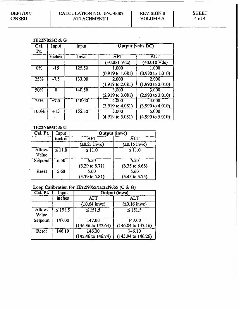
lE22N055C & GCal. Input Input Output (volts DC)Pt._ ines Inwc AFT ALT
(+0.081 Vdc) (±+0.010 Vdc)0% -15 125.50 1.000 1.000
(0.919 to 1.081) (0.990 to 1.010)25% -7.5 133.00 2.000 2.000
(1.919 to 2.081) (1.990 to 2.010)50% 0 140.50 3.000 3.000
_ (2.919 to 3.081) (2.990 to 3.010)75% +7.5 148.00 4.000 4.000
(3.919 to 4.081) (3.990 to 4.010)100% +15 155.50 5.000 5.000
(4.919 to 5.081) (4.990 to 5.010)
1E22N655C & GCal. Pt. Input Output (inwc)
_ inches AFT ALT____ (±0.21 inwc) (±0.15 inwc)
Allow. 5 11.0 < 11.0 • 11.0Value
Setpoint 6.50 6.50 6.50(6.29 to 6.71) (6.35 to 6.65)
Reset l 5.60 5.60 5.601 (5.39 to 5.81) (5.45 to 5.75)
Loop Calibration for 1E22N055/1E22N655 (C & G)Cal. Pt. I Input Output (inwc)
inches AFT J ALT(±0.64 inwc) _i (±0.16 inwc)
Allow. • 151.5 • 151.5 • 151.5Value
Setpoint I 147.00 147.00 147.00(146.36 to 147.64) (146.84 to 147.16)
146.10 146.10 146.10l__ ___ (145.46 to 146.74) (145.94 to 146.26)

DEPT/DIVC/NSED
CALCULATION NO. IP-C-0087ATTACHMENT 2
REVISION 0VOLUME A
SHEETI of 2
RESULTS SUMMARY
The following tables list the applicable results of this calculation:
i i :; ' ' :' :::n" i~ ii i .r ....... . i
Ikidiiz Copoet Sett-ing T; i; 4-er-Ancs I ---:- -,I-
lE22-N055 (C G) ± 0.081 Vdc + 0.010 VdclE22-N655 (CG) ± 0.21 inwc ± 0.15 inwc
ei ;.----:E ii~j.... -iiii S iP;i~.-i ... , t d: Ti-iW! ii:,.;Pii -:tiii iF~iiiiiiiit~ii isi
i'''l b '''i ' C'-U'Mi'.21j-'' L iA iF?' ii :j iii~
Compnen BIN - Sepi .tl::esx? . g:et AsFond C As-0 :
IE22-N655 (C,G) ATM 6.50- setpoint + 0.21 ± 0.15lE22-N655 (C,G) Loop 147.00 - setpoint ± 0.64 ± 0.161E22-N655 (C,G) ATM 5.60 - reset + 0.21 ± 0.15IE22-N655 (C,G) Loop 146.10 - reset + 0.64 ± 0.16
I I 5 oi
1E22-N655 (C,G) Loop 1"51.5 inwc

DEPT/DIVC1NSED
CALCULATION NO. IP-C-0087ATTACHMENT 2
REVISION 0VOLUME A
SHEET2 of 2
PI j Ozz,
4zpec; cm
_ j ac.t 0,., W AQi0L, l; ;
Heise Digital Model 901B 0 - 160 inches ±0.3392 inwc(or equivalent) Temp band of
(20°F to 120°F)Fluke 45 (or equivalent) Range appropriate to ±0.004 Vdc
measure 1-5 Volts(slow resolution)
Precision Resistor NA 250 Q 0.02 Q
usi--gl: . 51i V 5; "~;- -:.:.iUS~/eehnical SpecificationStpis
C.. po.nen.t' , Ao. wal Val&.. .: lecia Sif:'to
_b . Design Setpoi . . SJeci Li:
1E22-N655 (C,G) < 11.0 inches/ Tech. Spec. Table 3.3.5.1-16.5 inches Item 3.e /
ORM Tbl 5,Item 3.e
DEPT/DIVC/NSED
CALCULATION NO. IP-C-0087ATTACHMENT 3
REVISION 0VOLUME A
SHEET1 of 5
I
Letter CPS-TTI-0069File No. B99-00(12-21)-L
December 21, 2000
Tabulation of Pressure Transmitter Elevations(4 Pages Attached)

DEPT/DIVC/NSED
CALCULATION NO. IP-C-0087ATTACHMENT 3
REVISION 0VOLUME A
SHEET2of5
IIAmerGenainton
1OM
December 21,2000CPS-tTI-0069
B99.00(12-il)-L
Mr. Brian M. HaynesTaamn Technologies, Inc1901 So. 6' StreetOmaha, NE. 68108
Subject: Walk Down Information
Dear Mr. Haynes:
The pwpose of this correspondence is to formally transmit CPS walk down infonnationfor the attached transmitters. This walk down information was obtained to supp-rtdevelopment of the following calculations-
IP-C.0087 (First Priority)IP-C-002 (First Priority)IP-CD0084 (First Priority)IP-C-0070 (First Priority)IP-C4067 (First Priority)IP-C-0076IP-C-058IP-C0059
IP-C-0094IP.C.0073IP-C-0073IP-C.0066IP-C.0060IP-C-0064 (Previously Provided)IP-Co0077 (Previously Provided)IP-C-0083 (Previously Provided)
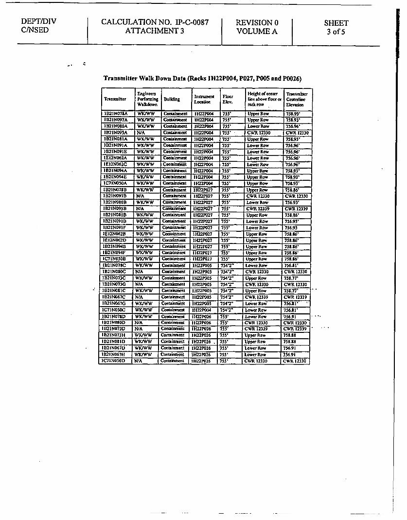
Construction Work Requests (CWR) 12330 and 12339 provide specific transmittercenterline elevation data in instrument racks IH22P004, IH22P027, tH22POO5 andIH22P026. Transmitter centerline data obtained In each CWR was verified usin~g knownbenchmark elevations. 7he majority of baritters in the attacbed listing were notincluded in cither CWR.
TeU transmitters on the attached listings are annotated as being in the upper or lower rowof the rack. Each instrument Tack's row elevation is assumed to be equivalent to thecenterline elevation of the individual transmittcrs recorded in the CWRs. In the caseswhere several transmiter elevations ftgm the same row were recorded in the CWRs, theelevations were averaged and these values were used to speify the transmitter centerlineckvation. This assumption is valid since the walk downs performed in support of thisletter confirmed that all transmitters in the same row for a given rack, are very close to thesame elevation. Any differences in elevation were not discenable by inspection or bymeasuring from floor or grating elevation to transmitter centerline. The transmitters thatwere included in the CWR survey are listed by the CWR they were surveyed in.
I
DEPT/DIVC/NSED
CALCULATION NO. IP-C-0087 REVISION 0ATTACHMENT 3 VOLUME A
SHEET3 of 5
I
Transmitter Walk Down Dsta (Racks I H22P004, P027, P005 and PW026)
Engineer s Ha'ght ofeenter Trteunmier
Tranmitter Performing Building Lonation Ekvr Ihe o or CetiWalkdownn ra row Elvaion
1921N078A ,WKfWW Containmet 1IH22P004 755' Upper Row 75S.93'
IB21N097A WVKAW Containme IH22PG04 755' Upper Row 75193'
IB21NO3OA WIJWW Coti=men H IH22P004 755' Lower Row 75&A6
IB21N4095A NWA Ccaainment 1 22P004 755' CWR 12330 CWR 12330
IB2INO0IA WICiWW Costainment 1H22PCO4 755' Upper Row 758.93'
IB2 1N091A WXfWW CostainmeWt 1K22P004 755' Lower Row 756.96'
182 IN091E WKIWW Cootaimnem IHZ2P004 755' Lower Row 756.96'
IE12NO62A WKJWW Cotainment 1H22P004 755' Lower Row 756.96'
IE12NO62C WKWW CoutainmeWt 1122P004 755' Lower Row 756.96'
IB21N094A WK/WW I H22P004 755' Upper Row 758.93'
IB21ND94E WKIWW Contaimk nt 1122P004 755' Upper Row 75S.93'
IC71NM50A W tWW Cae=t IH122F4 755' Upper Row 75.93'
1B2 1IN071B WKAWW Conliment 11122P027 755' Upper Row 758.16'
1B21N097B INA ContAkmne 11 P027 755' CWR 12330 CWR 12330
1021NO0B WKIWW Cadlinent IH22P027 755' Lower Row 756.93'
IB21N095B NWA Containment IH22P027 755' CWR 12339 CWR 12339
IB21NO81I3 WKJWW Conainment I H2PO27 755' Upper Row 75S.36'
IB2IN091D wKI w B G inment I H22P027 755' Lower Row 75693'
I B21NO91F W}IWW Comiament IH22P027 755' Lowerfow 756.93
IE12N062B WKWW Coutinment IH22P027 755' Upper Row 758.S6'
IE12N062D W3UWW Cerainment I H22P027 755' Upper Row 758.86'
IB21N094B W/KWW Cmeainmnd 210227027 755' Upper Row 758.36'
IB21N094F WKAWW Coeiunem InImV27 755' Upper Row 75t16'
IC71NOSOB WKtWW Containment H122P027 755' Upper Row 753.86'
11321N078C WKIWW Containment IH22PODS 7542' Lowr Raw 756.581'
IB2INOSOC NIA Contanimet IH22P005 754'Z' CWR 12330 CWR 12330
IB211NO73C WK(WW Containment IH22P05 754'2 Upper Row 756.77'
IB2 1N473G NA Containment 1IH22P005 7542 ClWR 12330 CWR 12330
1I2IN4t IC WKJWW Cofttakemt 1IMP005 7542" Upper Row ' 753.77 ' .
1B21N067C NtA Contaaumidn 1H22P005 754'2- CWR 12339 CWR 12339
1B2 1N067G WKIWW ContaimentI IH22POO5 754'2" Lower Rov 756.2'
IC7INOSOC WK2WW Contaiment IImP004 7547' Lower Row 756.3 I'
9IN21N073D WK)W' Comtineunt I 1122P026 755' Lower Row 756.91
IB21NO20D N/A Contaimot I(22P026 755' CWR 12330 CWR 1233D
I B21N073D WA Comalnenw IH22P026 755' CWR 12339 CWR 12339
IB21N073H WKtWW Contuinm et IH22P026 755' Upper Row 753.38
IB21N081D WKUWW Coctinment IH22P026 . 755' Upper Row 753.38
I12 IN067D WKWW Containment IH22P026 755' Lower Row 756.91
1B21N0671 WKWW Containment IH22P026 755' Loer Row 756.91
IC7INOSCOD A Containtenit IH22PC26 755' CWR 12330 CWR 12330

DEPT/DIVCINSED
CALCULATION NO. IP-C-0087 REVISION 0ATTACHMENT 3 VOLUME A
SHEET4 of 5
-
Transmitter Walk Down Data (Remaining Instruments)
Tranmitter ngineer Istrument Flo Lfine aof vne or TrnmtePernoring Building ain lv Lie Acut of ontr ElvtoWaflkFown or CWR row
71 21N4400A WKIWW Conaumsnent SPS100 755- 27.75" 757312'
IB21N400B ?VA Contalhmnt SPS101 7542' CWR 12339 CWR 12339
1B2 1N400E WYWW Co hNt ent SPS.102 755- 2125' 757.35'
IB21N400F WXIWW Cotirunent S'S103 755' 2r 75733'
IC7 1N052A WKIWW Turbine N -104 762' 3625' 765.02'
IC71NO52B WKIWW Tutbine K-122 762' 5625' 766.69'
IC71N052C WKAVW Turbine N-104 762' 56.25- 766.69'
IC71N052D WKIWW Turbine K -122 762' 5625- 766.69'
IB21N076A WKAW Thbsne N-112 7695- 5425- 774.02'
1I 21 076B WK/WW Turbine N -11 9 762' s55.Sr 766.66'
IB2 076C WKWW Turbine M-106 762' 55.5 766.63'
IB21076D WKlWW Turbine N-109 769.5 5425 774.02'
IE22N055C WKIWW Fuel AH-1 26 73' UJ7 741.06'
IE22N0550 WK _WW Fuel AR -116 737' 4.7S 74.06'
Revised Walk Down Data (Previously Provided by CPS-Tfl-0067)
Enginers Insrurnen Floor Heigin ofcentcr Trnmte] Ihb enIv | rluneft |Floev Llne above floor|EvaoTransruker PerforinhIg Building L.ocation Elev. LnWbefloo Elevation
IE12N055A WVIWW Aux.Bdg IH22POIS 707' 6' 46M' 711.35'
1E12N055C W K WW AWL Bldg IH22P055 707' 6" 22S 709.38'
1021N068A WKIWW Containment IH22P004 755' CWR 12330 CWR 12330
IR2INO6SE W _JWW Containment IH22P04 755' Upper Row 752.93'
I B21N401A WIAVW Containment SPS'I00 755' 48W5- 759.1'
1R21N401D WKIJB Containment SPS-101 754'2" 32.25" 756.85
1D21N0688 WKIJA Containment IH22P027 755' Upper Row 75J8S6'
IB21N06SF WKIJA Sontin-nent . I1H22P027 755' Upper Row 758.86'
112211N4401E WKJA Contient SPS.102 75S' 49' 759.03 -'
IB1IN40IF WKJJA Containment SPS-103 755' 41.75' 759.06'
Walk downs petforned b:
W5IS.Kokff J4 12 P4 h J.8no B.-.=//;~
W. Whi h t h 1. Ashcraft J /2 /h/
k.w*/1<)f/R Wsesoo.
DEPT/DIV CALCULATION NO. IP-C-0087 REVISION 0 SHEETC/NSED AITACHMENT3 VOLUME A 5 of 5
This approach will provide the most accurate means of providing transmitter centerlineelevation data. In this regard, the information previously provided by letter CPS-lTI-0067 is supereded by this letter.
Some of the transniners walked down were not included in the surveys conducted by theCWRs. In these cases. centcrline measuruents were recorded and added to the top offloor or grating clevations to derive the transmitter centerline elevations.
If you have any questions regarding this matter please feel free to contact myself atextension 3442 er Steve Koleltat extension 4031.
J.W. Smith, Project ManagerNSED C&l Design Enginecrn
.. .. ... I ..

DEPT/DIVC/NSED
CALCULATION NO. IP-C-0087ATTACHMENT 4
REVISION 0VOLUME A
SHEETI of 3
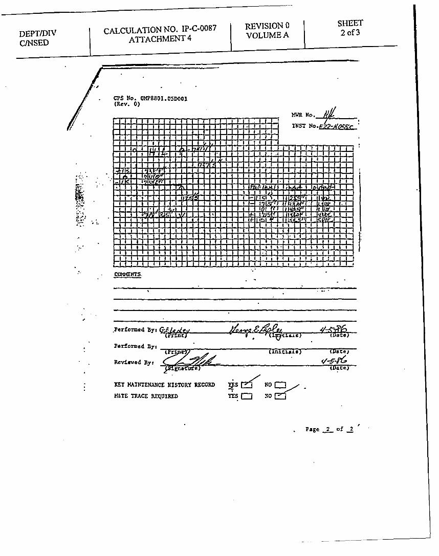
Instrument Calibrations Data Sheet Walkdown Information, CPS OMP8801.05D001for Transmitter IE22N055C & G, dated April 5,1986.
(2 Pages Attached)
DEPT/DIV CALCULATION NO. IP-C-0087 | REVISION 0CINSED I ATTACHMENT 4 j VOLUME A
SHEET2 of 3
CPS No. W8801.05DO01(Rev. 0)
MWR No. - _
TNST *EZ:&0.Ozc-
,,h ,,,h , ;:P
... ..
;. . .J- , - IV. - .
CEMMINTS.
.Perfcoed Bysc j ) -/A
Parfozmed BysLipr, (initlais) (Date)
Reviewed Byl
D {Date)
IzY MAINTErNANCE HISTORY RECORD NDM&TE TRACE REQUIRED YES a s o
Page 2 of 2

DEPT/DIVCYNSED
CALCULATION NO. IP-C-0087ATTACHMENT 4
REVISION 0VOLUME A
SHEET3of3
I
CPS No. OT8801.C5DOO1(Rev. 0)
MWR No. 49
1VST No?2M :~
W.-
... .
R:e
I',:,
CotelITS.
. . .11
Ptrfozed Bys
Pesorfed By:
Reviewed By:
-c, Cr~gte4SFrt) / xmu ,A L- -
(Date)-
(twI0 (Jit.a.ls) (DateJ
1 lF8L a S -tD te)
IEY MAITLNA2lCE HISTORY RECORD
M&TE TRACE BEQUIREDVAMEJ
NO =w
210 2
Page 2 of 2