attachment 1 - design and construction - utah
TRANSCRIPT

Attachment 1 - Design and Construction

2020 PCSMF Landfill Permit Application Part III December 21, 2020
Page 4
SECTION 3 – ENGINEERING REPORT
3.1 LOCATION STANDARDS
Prior to preparation of this permit application, a Preliminary Location Screening Analysis
(Screening Analysis) was performed to assess the suitability of the PCSMF site for use as a soil
repository. The Screening Analysis was used to determine if the PCSMF site met the criteria for
Class I Landfills under the State of Utah regulations R315-302-1. Appendix J presents the
updated Screening Analysis detailing how the PCSMF meets the location standards.
3.2 ESTIMATED FACILITY LIFE
Based on the known soil disposal needs, the projected life of the facility is scheduled to be
approximately 10 years. Currently, approximately 35,000 cubic yards of potentially
contaminated soils are stored on the PCSMF site and approximately 60,000 cubic yards of
potentially contaminated soil will be generated by the development of the Arts & Culture
project. Additional projects that are scheduled by PCMC include Highway 248 , Homestake,
Boothill, Spiro and the QWTP projects. These additional projects are anticipated to generate an
additional 22,814 cubic yards of soil. The remaining capacity of 24,086 cubic yards will be used
for unidentified projects within the Park City Soil Ordinance Boundary.
The facility capacity is based on minimal excavation in the Cell 2 footprint. The airspace for Cell
2 is largely based on the capacity developed by moving the existing 35,000 cubic yards of soil
stockpiled on site into Cell 1. Additional capacity can be generated by dropping the elevation of
the bottom of Cell 2. Clean soils generated from additional Cell 2 excavation can be utilized for
landscaping on site or removed from the PCSMF project property.

2020 PCSMF Landfill Permit Application Part III December 21, 2020
Page 5
The facility life is presented in the following table:
3.3 FACILITY DEVELOPMENT AND OPERATION
The current plans call for development of the facility in two cells; these are shown on Drawing
3, Appendix B. The development of Cell 1 will include construction of site access roads and
storm water control structures. Presently, with the exception of some dirt roadways there is
not vehicle access around the site. Fill needed for the initial berm construction (32,000 cyd) will
be generated from the Cell 1 cut (34,000 cyd). The floor of the landfill cells is designed with a
slope of 4.9% to generate the required soil storage capacity and to avoid large bedrock
excavations. All storm water will be diverted in an eastern direction away from active working
areas and toward natural drainages on the property. Based on the soil disposal need
projections we anticipate that Cell 1 will accommodate the projected waste stream for
approximately 1 year depending on the development of the Arts & Culture project. During this
time , the development of Cell 2 will be designed, permitted, and constructed.
Soil Disposed Remaining Capacity
(Cubic Yards) (Cubic Yards)
141,900 *
Cell 1 2021 Relocate Existing Soils 35,000 106,900
1/2 of Arts and Culture 30,000 76,900
Cell 2 2022 1/2 of Arts and Culture 30,000 46,900
2023 TBD 5,000 41,900
2024 TBD 5,000 36,900
2025 TBD 5,000 31,900
2026 TBD 5,000 26,900
2027 TBD 5,000 21,900
2028 TBD 5,000 16,900
2029 TBD 5,000 11,900
2030 TBD 5,000 6,900
2031 TBD 5,000 1,900
* Initial Capacity Site Capacity

2020 PCSMF Landfill Permit Application Part III December 21, 2020
Page 6
3.3.1 Liner
Liner installation for Cell 1 is anticipated for early summer of 2021 in preparation for soil
acceptance in late summer. The landfill floor and side slope will be lined using a primary HDPE
liner and secondary GCL liner. Preparation for liner placement will include removal of oversize
cobbles in order to protect liner materials, a geocomposite material will be placed over HDPE
liner to protect the during soil placement. The geocomposite (drain net) will also be utilized for
the collection and management of potential leachate. Cell 2 will utilize the same liner
components and will tie into the Cell 1 liner materials to maintain a continuous lined facility.
3.3.2 Fill Method
Waste soil will be placed at the toe of work face and spread horizontally in six-inch to twelve-
inch layers and compacted with site equipment. The placement of soil will begin at the bottom
of Cell 1 and will not be pushed down the side slopes. Soils will not be placed at the top of the
side slopes and pushed down into the cell to minimize stress on the liner system components.
The eastern portion of Cell 1 will be left unfilled to provide liquid storage associated with the
leachate collection system. Drawing 3, Appendix B presents the location of the Leachate Pond
within Cell 1 boundaries.
3.3.3 Daily, Intermediate and Final Cover
3.3.3.1 Daily and Intermediate Soil Cover
Since all of the waste delivered to the PCSMF will be soils, there will be no need for daily or
intermediate cover soils.
3.3.3.2 Final Cover
The PCSMF staff will initiate final cover system installation within 30 days after soil disposal
reaches the final elevation in any particular landfill closure phase with installation of the final
cover being complete within 180 days after initiation.
It is anticipated that final cover will be placed over the landfill areas in three separate events
(phases) as sufficient area is brought to final elevation. The minimum area planned for
placement of final cover will be approximately two acres. Closure phases may be adjusted to
better accommodate landfill operation and waste placement.

2020 PCSMF Landfill Permit Application Part III December 21, 2020
Page 7
The engineered final cover system will prevent surface water infiltration (thereby minimizing
leachate generation), maintain slope stability, control surface water and erosion, and be
capable of supporting vegetative cover. The vegetative cover will be selected with shallow root
systems to reduce cover soil penetration. The cover will be constructed as indicated on the
permit drawings in Appendix B. Beginning at the surface, the planned cover consists of a
minimum of 6-inches of topsoil, 18-inches site soils, geofabric, HDPE and GCL over the managed
soils. Prior to construction of the final cover in each of the stages, an engineering design
package consisting of Drawings, Specifications and a QA/QC plan will be submitted to the
DWMRC for approval.
Final cover side slopes will be constructed and maintained at a maximum of 3H:1V. The final
cover surface will also contain access roads with shallow ditches to provide access for final
cover maintenance and break up long drainage paths to minimize erosion.
3.3.4 Elevation of Final Cover
As illustrated on drawings in Appendix B, the natural ground surface at the site of the landfill
slopes generally downward from west to east. Within the proposed landfill footprint, the
natural elevation of the surface drops from approximately 6,710 to 6,650 feet with the final
cover having a maximum elevation of 6,720 and a minimum elevation of approximately 6,670
feet above mean sea level (msl).
3.3.5 Equipment Requirements and Availability
Section 1.5 and 1.6 of Part II – General Report, contains a listing of equipment and personnel to
be utilized at the facility.
3.4 MONITORING SYSTEM DESIGN
3.4.1 Ground Water Monitoring System
The installation of the ground water monitoring system is scheduled to be concurrent with the
general development of Cell 1. The locations of the proposed wells are shown in Appendix B
and discussed in the Ground Water Monitoring Plan (Appendix E).

2020 PCSMF Landfill Permit Application Part III December 21, 2020
Page 8
3.4.2 Surface Water
In general, surface water will be prevented from running into the active landfill area by ditches
and berms created during perimeter road construction. Run-off from the final cover will also be
managed by using access roads equipped with berms and ditches. The perimeter road will
divert surface flows initiated off-site around active areas of the landfill to existing nearby
drainages. PCSMF personnel will inspect the constructed drainage system quarterly. Temporary
repairs will be made to any observed deficiencies until permanent repairs can be scheduled.
PCSMF personnel or a licensed contractor will repair drainage facilities as required.
3.4.3 Leachate Management
Among the possible problems created by waste storage in the landfill is the possible
contamination of soil, surface water, or ground water from storm water contacting or passing
through the potentially contaminated soils. Due to the relatively low precipitation, the nature
of the waste, and high evapotranspiration rates associated with the semi-arid climate at the
site, the quantity of water infiltrating the landfill is predicted to be very small and subsequent
leachate generation low. The landfill cover is designed to minimize infiltration and promote
runoff. Furthermore, liquid waste will not be allowed in the landfill.
What leachate is generated will be collected by the leachate management system. The leachate
management system will consist of a geocomposite drainage material to provide lateral drainage
of leachate directly above the liner system.
Cell 1 bottom liner slope will be constructed with a minimum slope of approximately 4.9% (west
to east) in order to direct leachate flows to the Cell 1 leachate pond.
As currently planned the largest area to be lined/open at one time will be Cell 1, approximately
115,000 ft2 (2.6 acres). The leachate pond has been sized to completely capture all run-off from
the design storm falling on this area. The minimum required pond capacity in this scenario is
0.71 acre-ft. The area set aside for the leachate collection/evaporation pond is approximately
1/2 acre in size. This requires an average pond depth of 1.4 feet. Cell 1 is 12 in height at the
eastern side where the leachate pond will be located. The geometry of Cell 1 results in a
minimum of 10 feet of available freeboard and provides adequate capacity in the event the
design storm occurs when the pond is not completely empty. The 100-yr 24-hour storm event
is utilized for the sizing of the leachate pond. The 100-yr design storm is a conservative

2020 PCSMF Landfill Permit Application Part III December 21, 2020
Page 9
parameter since only the 24-hour, 25-yr storm is required by regulation. Leachate ponds will be
established in each of the cells.
3.4.4 Landfill Gas
Due to the nature of the waste (soils) to be managed at the PCSMF, no landfill gas will be
generated and no landfill gas system will be installed.
3.5 DESIGN AND LOCATION OF RUN-ON/RUN-OFF CONTROL SYSTEM(S)
The two nearest weather stations to the site are in the Park City Fire Station 31 and the Park
City Radio stations. The Park City Fire Station 31 and at the Park City Radio weather stations
show the average annual rainfall to be 20.62 and 21.17 inches, respectively. Both these stations
are located at similar elevation and several miles west of the site. Appendix K – Hydrologic
Assessment presents the precipitation data for the Park City area.
3.5.1 Run-On from a 25-Year, 24-Hour Storm
The site is located on the east facing slope of the Park City Hill with potential for surface flows
to run toward the site from the eastern slopes of the Park City Hill. The land immediately uphill
from the site is currently used to grow alfalfa or other crops. There is a shallow drainage that
transports surface waters from the west and north of the site towards Highway 248. Surface
flows from west and north of the facility will be diverted around the facility until they can be
reintroduced to the natural drainage along Highway 248.
A perimeter road consisting of ditches and berms will be constructed around the landfill to
create a barrier to surface water flows that is capable of transmitting flows from a 25-year, 24-
hour storm (2.61 inches - NOAA Atlas 14) around the site. The high point of the perimeter road
will be located at the western boundary of the site and divert any potential run-on north and
south of the facility. Preliminary calculations of the peak flow rates from the predicted run-on
areas used for initial design of the storm water collection ditches are provided in Appendix K –
Hydrologic Assessment.

2020 PCSMF Landfill Permit Application Part III December 21, 2020
Page 10
3.5.2 Run-Off from a 25-Year, 24-Hour Storm
The design for the landfill will incorporate a run-off control system that will divert the surface
flows resulting from a 25-year, 24-hour storm (2.61 inches – NOAA Atlas 14) that falls on the
landfill cover. The proposed final cover surface will direct flows to perimeter berms and ditches
that will convey all storm water to the storm water pond located north of Cell 1 as indicated in
Appendix B.
Preliminary calculations of the flow rates from the predicted runoff to be used for design of the
storm water collection ditches are provided in Appendix K - Hydrologic Assessment. All ditches
will be constructed with 2H:1V side slopes, maximum depth of flow was calculated to be 1.39
feet in the run-off channels.
Berms and ditches will be incorporated into the active landfill areas to direct the precipitation
away from the working faces.
PCSMF personnel will be responsible for the maintenance of the slopes and drainage systems to
ensure the efficient operation of the run-off system.
As shown on several of the permit drawings (Appendix B) one storm water pond will be
constructed at the site for detention and control of storm water run-off. In order to account for
the potential presence of some water in the pond due to antecedent moisture, the design
storm event the pond will be sized for will be the 100-year 24 hour storm (3.22-inches - NOAA
Atlas 14).
The PCSMF is designed and will be constructed so as not to cause point or non-point source
discharges to surface waters in violation of the CWA or in violation of State of Utah water
quality management plans approved under Section 208 or 319 of the CWA. Prior to initiation of
work at the site a Utah Pollutant Discharge Elimination System (UPDES) permit will be obtained
by PCMC.

100 F
T O
FFSET
1
0
0
F
T
O
F
F
S
E
T
CHECKED BY:
COPYRIGHT:
DESIGNED BY:
DRAWN BY:
CAD DWG FILE:
PROJECT NO.:
REFERENCE:
BACKGROUND IMAGES: USGS TOPO MAP (7.5 MIN SERIES)
PROVIDED BY UTAH AGRC
SHEET
B
2702 South 1030 West, Suite 10
Salt Lake City, Utah 84119
(801)270-9400 (T)
ideas for a changing world
445 Marsac Avenue
Park City Municipal Corporation
TITLEPC SOIL MANAGEMENT FACILITY
C
A
431 2
DATEDESCRIPTION
ISSUE:
1
SHEET TITLE
C
B
A
(435) 615-5000 (T)
Park City, Utah
(801)270-9401 (F)
VICINITY MAP
INDEX
1 TITLE SHEET 2 GENERAL ARRANGEMENT 3 LANDFILL DEVELOPMENT 4 FINAL COVER 5 CLOSURE PHASES 6 ELEVATION VIEW 7 DETAILS
LOCATION MAP
SITE MAP
(NOT TO SCALE)
PARK CITYSOIL MANAGEMENT FACILITY
2020 PERMIT APPLICATION
PROPERTY
BOUNDARY
PROPERTY
BOUNDARY
REFERENCE:
BACKGROUND IMAGES: 2018 NAIP,
PROVIDED BY UTAH AGRC
K
E
A
R
N
S
B
L
V
D
.
H
IG
H
W
AY
40
RIC
HA
RD
SO
N F
LA
T R
D.
EXIT 4
12/18/20PERMIT

1
0
0
F
T
O
F
F
S
E
T
6
6
4
0
6
6
5
0
6
6
6
0
6
6
7
0
6
6
7
0
6
6
7
0
6
6
8
0
6
6
8
0
6680
6
6
9
0
6
6
5
0
6
6
6
06
6
7
0
6
6
8
06
6
9
0
6
7
0
0
6710
AB
A'
B'
DD'
C'C
CHECKED BY:
COPYRIGHT:
DESIGNED BY:
DRAWN BY:
CAD DWG FILE:
PROJECT NO.:
ARANGEMENT
B
2702 South 1030 West, Suite 10
Salt Lake City, Utah 84119
(801)270-9400 (T)
ideas for a changing world
445 Marsac Avenue
Park City Municipal Corporation
GENERALPC SOIL MANAGEMENT FACILITY
C
A
431 2
DATE DESCRIPTION
ISSUE:
2
SHEET TITLE
C
B
A
(435) 615-5000 (T)
Park City, Utah
(801)270-9401 (F)
PROPERTY
BOUNDARY
REFERENCE:
BACKGROUND IMAGES: 2018 NAIP,
PROVIDED BY UTAH AGRC
K
E
A
R
N
S
B
L
V
D
.
R
IC
H
A
R
D
S
O
N
F
L
A
T
R
D
.
SOIL STOCKPILE
~35,000 CYD
(TO BE RELCATED
12/18/20 PERMIT

1
0
0
F
T
O
F
F
S
E
T
6
6
6
0
6
6
7
0
6
6
8
0
6
6
9
0
6
6
4
0
6
6
5
0
6
6
6
0
6
6
7
0
6
6
7
0
6
6
7
0
6
6
8
0
6
6
8
0
6680
6
6
9
0
6
6
5
0
6
6
6
06
6
7
0
6
6
8
06
6
9
0
6
7
0
0
6710
-
4
.
9
%
6
6
6
0
6670
6680
AB
A'
B'
DD'
C'C
STORM
WATER
POND
MW-2
MW-3
MW-1
CHECKED BY:
COPYRIGHT:
DESIGNED BY:
DRAWN BY:
CAD DWG FILE:
PROJECT NO.:
DEVELOPMENT
B
2702 South 1030 West, Suite 10
Salt Lake City, Utah 84119
(801)270-9400 (T)
ideas for a changing world
445 Marsac Avenue
Park City Municipal Corporation
LANDFILLPC SOIL MANAGEMENT FACILITY
C
A
431 2
DATE DESCRIPTION
ISSUE:
3
SHEET TITLE
C
B
A
(435) 615-5000 (T)
Park City, Utah
(801)270-9401 (F)
REFERENCE:
BACKGROUND IMAGES: 2018 NAIP,
PROVIDED BY UTAH AGRC
PROPERTY
BOUNDARY
K
E
A
R
N
S
B
L
V
D
.
R
IC
H
A
R
D
S
O
N
F
L
A
T
R
D
.
CELL 1
CELL 2
(FUTURE)
SOIL STOCKPILE
~35,000 CYD
(RELOCATED TO CELL 1)
CELL 1 EXCAVATION
34,000 CYD (CUT)
MAX DEPTH 16.8 FT
PERIMETER ROAD BERM
32,000 CYD (FILL)
MAX HEIGHT 19.8 FT
LEACHATE
POND
12/18/20 PERMIT
MONITORING WELL
(PROPOSED)

1
0
0
F
T
O
F
F
S
E
T
-
2
.
0
%
6
6
7
0
6
6
8
0
6
6
9
0
6
7
0
0
6
7
1
0
6
7
2
0
6
6
6
0
6
6
7
0
6
6
8
0
6
6
9
0
6
6
4
0
6
6
5
0
6
6
6
0
6
6
7
0
6
6
7
0
6
6
7
0
6
6
8
0
6
6
8
0
6680
6
6
9
0
6
6
5
0
6
6
6
06
6
7
0
6
6
8
06
6
9
0
6
7
0
0
6710
AB
A'
B'
DD'
C'C
STORM
WATER
POND
MW-2
MW-3
MW-1
CHECKED BY:
COPYRIGHT:
DESIGNED BY:
DRAWN BY:
CAD DWG FILE:
PROJECT NO.:
COVER
B
2702 South 1030 West, Suite 10
Salt Lake City, Utah 84119
(801)270-9400 (T)
ideas for a changing world
445 Marsac Avenue
Park City Municipal Corporation
FINAL PC SOIL MANAGEMENT FACILITY
C
A
431 2
DATE DESCRIPTION
ISSUE:
4
SHEET TITLE
C
B
A
(435) 615-5000 (T)
Park City, Utah
(801)270-9401 (F)
REFERENCE:
BACKGROUND IMAGES: 2018 NAIP,
PROVIDED BY UTAH AGRC
PROPERTY
BOUNDARY
K
E
A
R
N
S
B
L
V
D
.
R
IC
H
A
R
D
S
O
N
F
L
A
T
R
D
.
FINAL LANDFILL SURFACE
TOTAL AIRSPACE: 170,800 CYD
COVER VOLUME: 28,900 CYD
NET AIRSPACE: 141,900 CYD
MAX FILL HEIGHT (38.1 FT)
12/18/20 PERMIT
MONITORING WELL
(PROPOSED)

1
0
0
F
T
O
F
F
S
E
T
-
2
.
0
%
6
6
7
0
6
6
8
0
6
6
9
0
6
7
0
0
6
7
1
0
6
7
2
0
6
6
6
0
6
6
7
0
6
6
8
0
6
6
9
0
6
6
4
0
6
6
5
0
6
6
6
0
6
6
7
0
6
6
7
0
6
6
7
0
6
6
8
0
6
6
8
0
6680
6
6
9
0
6
6
5
0
6
6
6
06
6
7
0
6
6
8
06
6
9
0
6
7
0
0
6710
STORM
WATER
POND
PHASE III
PHASE II
PHASE I
MW-2
MW-3
MW-1
CHECKED BY:
COPYRIGHT:
DESIGNED BY:
DRAWN BY:
CAD DWG FILE:
PROJECT NO.:
PHASES
B
2702 South 1030 West, Suite 10
Salt Lake City, Utah 84119
(801)270-9400 (T)
ideas for a changing world
445 Marsac Avenue
Park City Municipal Corporation
CLOSUREPC SOIL MANAGEMENT FACILITY
C
A
431 2
DATE DESCRIPTION
ISSUE:
5
SHEET TITLE
C
B
A
(435) 615-5000 (T)
Park City, Utah
(801)270-9401 (F)
REFERENCE:
BACKGROUND IMAGES: 2018 NAIP,
PROVIDED BY UTAH AGRC
PROPERTY
BOUNDARY
K
E
A
R
N
S
B
L
V
D
.
R
IC
H
A
R
D
S
O
N
F
L
A
T
R
D
.
12/18/20 PERMIT
FINAL LANDFILL SURFACE
TOTAL AIRSPACE: 170,800 CYD
COVER VOLUME: 28,900 CYD
NET AIRSPACE: 141,900 CYD
MAX FILL HEIGHT (38.1 FT)
MONITORING WELL
(PROPOSED)

Section C-C' PROFILE
6625
6650
6675
6700
6725
6750
6625
6650
6675
6700
6725
6750
1+00 2+00 3+00 4+00 5+00 6+00 7+00 8+00
Section D-D' PROFILE
6650
6675
6700
6725
6750
6650
6675
6700
6725
6750
1+00 2+00 3+00 4+00 5+00 6+00 7+00
Section A-A' PROFILE
6675
6700
6725
6750
6675
6700
6725
6750
1+00 2+00 3+00 4+00 5+00 6+00
Section B-B' PROFILE
6650
6675
6700
6725
6650
6675
6700
6725
1+00 2+00 3+00 4+00 5+00
3
H
: 1
V
S
ID
E
S
L
O
P
E
(M
A
X
)
3
H
: 1
V
S
ID
E
S
L
O
P
E
(M
A
X
)
3
H
: 1
V
S
ID
E
S
L
O
P
E
(M
A
X
)
3
H
: 1
V
S
ID
E
S
L
O
P
E
(M
A
X
)
3
H
: 1
V
S
ID
E
S
L
O
P
E
(M
A
X
)
2% TOP SLOPE
2%
TO
P S
LO
PE
CELL 1 EXCAVATION
CELL 1 EXCAVATION
SOIL STOCKPILE
(TO BE RELOCATED TO CELL 1)
CELL 2 EXCAVATION
(TO BE DETERMINED)
SOIL STOCKPILE
(TO BE RELOCATED TO CELL 1)
SOIL STOCKPILE
(TO BE RELOCATED TO CELL 1)
CELL 2 EXCAVATION
(TO BE DETERMINED)
CELL 1 EXCAVATION
CHECKED BY:
COPYRIGHT:
DESIGNED BY:
DRAWN BY:
CAD DWG FILE:
PROJECT NO.:
VIEW
B
2702 South 1030 West, Suite 10
Salt Lake City, Utah 84119
(801)270-9400 (T)
ideas for a changing world
445 Marsac Avenue
Park City Municipal Corporation
ELEVATIONPC SOIL MANAGEMENT FACILITY
C
A
431 2
DATEDESCRIPTION
ISSUE:
6
SHEET TITLE
C
B
A
(435) 615-5000 (T)
Park City, Utah
(801)270-9401 (F)
12/18/20PERMIT
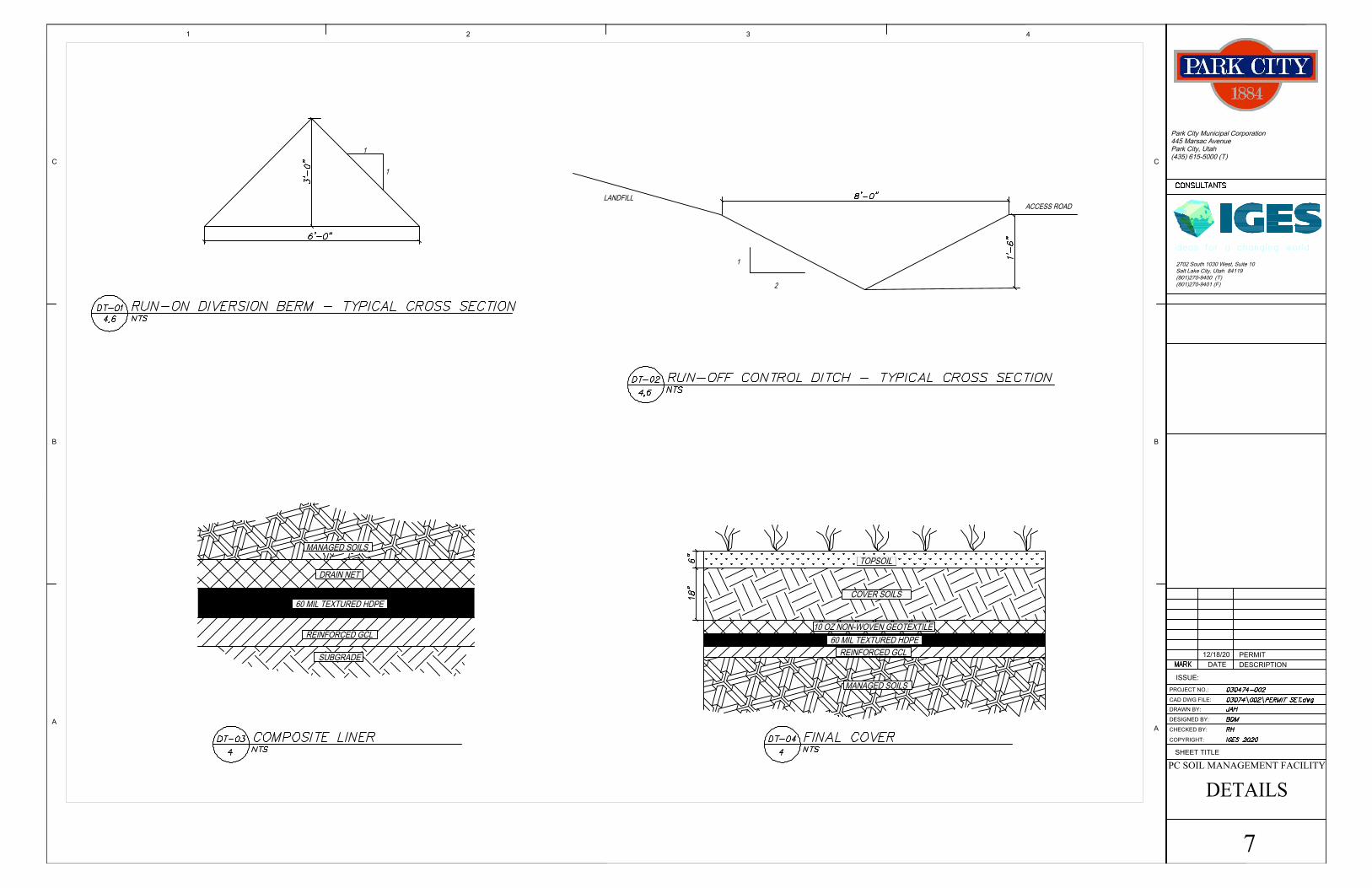
TOPSOIL
COVER SOILS
MANAGED SOILS
1
1
2
1
LANDFILL
ACCESS ROAD
SUBGRADE
REINFORCED GCL
60 MIL TEXTURED HDPE
DRAIN NET
60 MIL TEXTURED HDPE
REINFORCED GCL
10 OZ NON-WOVEN GEOTEXTILE
MANAGED SOILS
CHECKED BY:
COPYRIGHT:
DESIGNED BY:
DRAWN BY:
CAD DWG FILE:
PROJECT NO.:
DETAILS
B
2702 South 1030 West, Suite 10
Salt Lake City, Utah 84119
(801)270-9400 (T)
ideas for a changing world
445 Marsac Avenue
Park City Municipal Corporation
PC SOIL MANAGEMENT FACILITY
C
A
431 2
DATEDESCRIPTION
ISSUE:
7
SHEET TITLE
C
B
A
(435) 615-5000 (T)
Park City, Utah
(801)270-9401 (F)
12/18/20 PERMIT