attachment i to aep:nrc:4520-01 specification dcc ce …
TRANSCRIPT

ATTACHMENT I TO AEP:NRC:4520-01
SPECIFICATION DCC CE io7 QCS, REVISION 3REINFORCING STEEL SPECIFICATIONS

o l S
bI .
FORM QC 19REV. 6/70
INDIANA AND MICHIGAN ELECTRIC COMPANYDONALD C. COOK NUCLEAR PLANT CA C PI
ow, ,,.0
SPECIFICATION COVER SHEET
Specification No. Dated Revision No. Dated
DCC CE 107 QCS 3 March 26, 1969
ATTACHMENTS
TITLE: Reinforcing Steel Specifications
SYSTEM:All Class I and II Concrete
SCOPE OF REVISION: General
This document contains proprietary information of American Electric Power Service Corporation, andis to be returned upon request. Its contents may not be used for other than the expressed purposefor which loaned without the written consent of American Electric Power Service Corporation.
INTERNAL APPROVAL SIGNATURES
I
I

Revision 3i .|:v hi lMarch 26, 1969
S 't J INDIANA & MICHIGAN ELECTRIC COMPANYDONALD C. COOK TUCLE-0R PLANT
UNITS I & 2
l } __PEjt1FORCING STEEL SPECIFICATIONS
All reinforcing shall be deformed new billet open
hearth steel conforming to ASTM Specification A-615-68 Grade
+0.% Reinforcing is to be furnished and fabricated in accordance
with the instructions contained herein, the abovementioned
ASTM Specifications, and Buyer's detail drawings and bar
bending schedule-Form SD-3 (Dr-45). All bars that are to be
Cadweld spliced shall be so fabricated that both ends wfill
freely fit through the proper Cadweld sleeve.- Buyer will
furnish the fabricator one complete set of all such sleeves
for checking purposed. Buyer will also indicate on separate
release sheets or by appropriate marking the bars to be
Cadweld spliced. All reinforcing bars shall have U. S. standard
markings for: (1) Producing Mill, (2) Bar size, (3) Type steel.
Bars to be spliced by the Cadweeld splicing process
may be sawed, sheared or flame cut providing that the Cadweld
sleeve requirements are met.
CERTIFICATION TESTING AND ACCEPTANCE
Buyer will require certified mill tests reports for
each heat of steel in accordance with ASTM A-615-68 Specification
requirements. Mill tensile tests are to be made on the full
section of bars as rolled. In addition Buyer will have independent
tests taken to confirm compliance with ASTM A-615-68 for tensile
strength, yield point, and percent elongation for each heat.
1 NJ' o.
TQ NDCC C-so

-2-
Fabricator will be required to tag for identification and
segregate from other reinforcing steel Buyer's steel
requirements, which have been accepted as meeting the specifications.
All reinforcing steel requirements of Buyer must come from
this tagged and segregated source and written certification
to this effect shall be required for all fabricated steel
delivered to the project site. In addition to the written
certification each bundle of reinforcing delivered to the
project shall be tagged showing the heat number of the steel
manufacturer (Mill).
"CHECK" TEST REQUIREMENTS
Fabricator will be required to provide Buyer's
job site testing laboratory at Bridgman, Michigan, with six
(6) 3 feet long full size test specimens from each heat.
The end 12" of any bar shall be excluded. These-specimens
will be tested in accordance with the pertinent provisions
of.ASTM A615-68 for tensile strength, yield point and percent
elongation. With each new heat Buyer will provide fabricator
approximate quantities and sizes about one (1) week prior
to the receipt of the release for fabrication in order
that Fabricator can immediately ship the required test
specimens. It will be the Fabricator's responsibility to
notify Buyer when new heats are to be used. Fabricator will
be informed immediately when the test results are known.
aem 1y
*C ',

- 3 -
If two (2) specimens from the same heat fail the
required ASTHl tests,. the entire heat shall be rejected.
COLOR CODING AND BUNDLE MARKING
In addition to- the tagging required for conformance
to specifications Fabricator will be required to provide
identification tagging on all steel shipped to the project
site as set forth herein.
All reinforcing delivered-to the project site requires
two types of identification;
(1) A color tag designating the area in the plant
where the steel is to be. used.
(2) Metal tags identifying each Mark Number of
fabricated steel.
COLOR TAGS
All releases for reinforcing requirements will bear
a release number (RS-) each release ifill indicate the required
color tag which is to be used to identify the area in the
project where the material is to be'used. No writing should
appear on the color tag. Tags should be standard cardboard
or heavy paper of the proper color securely fastened to each
bundle of reinforcing. These tags should be strong enough
and waterproofed enough to arrive at destination in a condition
which will enable segregation of the bundles and their placement..
in the correct working area.
Rev. No.To OCC Crz -
Spec. No./I7 9! _5o
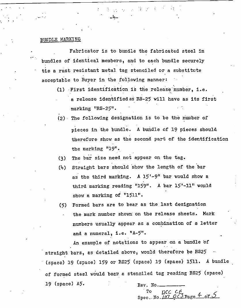
BUIIDLE MARKING
Fabricator is to bundle the fabricated steel in
bundles of identical members, and to each bundle securely
tie a rust resistant metal tag stenciled or a substitute
acceptable to Buyer in the following manner:
(1) First identification is the release number, ide.
a release identified as RS-25 will have as its first
marking "RS-25".
(2) The following designation is to be the number of
pieces in the bundle. A bundle of 19 pieces should
therefore show as the second part of the identification
the marking 1"19".
(3) The bar size need not appear on the tag.
(1) Straight bars should show the length of the bar
as the third marking. A 15'-9" bar would show a
third marking reading "'159". A bar 15'-11" would
show a marking of "1511".
(5) Formed bars are to bear as the last designation
the mark number shown on the release sheets. Mark
numbers usually appear as a combination of a letter
and a numeral, i.e. "A-5".
An example of notations to appear on a bundle of
straight bars, as detailed above, would therefore be RS25
(space) 19 (space) 159 or RS25 (space) 19 (space) 1511. A bundle
of formed steel would bear a stenciled tag reading BS25 (space)
19 (space) A5. Rev. No.
To 2CC P CoSlpec. -No. 107 Q C.3 Page --oL$..

. 1 j -5-
INSPECTION
The Purchaser or Purchaser's representative shall
have free access to the Fabricator's shop at all times while
work on Purchaser's material is being performed..
SCHEDULING OF DELIVERIES
In all cased the delivery schedules called for indicate
actual requirements. Delays.in delivery of the reinforcing
steel result in extension of the construction schedule and
cannot be tolerated. It is therefore essential that Fabricator
bear in mind that he must maintain deliveries as per the lead
time schedule agreed to and which will become an essential
part of any purchase order resulting from this inquiry.
'Rev. No6.To ICC Co
Spec. oI o~g x%

ATTACHMENT 2 TO AEP:NRC:4520-01
CALCULATION SD-040303-001UNIT I & 2 CONTROL ROD DRIVE MISSILE SHIELD REINFORCING
STEEL YIELD STRENGTH, REVISION 0

COOK NUCLEAR PLANT Page 1
CALCULATION COVER SHEET Total pages including attachments - 140
CALCULATION NO. SD-040303-001 REVISION NO. 0
SAFETY RELATED: Z YES El NO UNIT NO. 1 & 2
SYSTEM FUNCTIONAL CALC: El YES 0 NO SYSTEM Code: CNTMT
AEPNG FUNCTIONAL AREA: DES
TITLE:L UNIT 1 & 2 CONTROL ROD DRIVE MISSILE SHIELD REINFORCINGSTEEL YIELD STRENGTH
REASON FOR REVISION:
Initial Issue
Limitation: The value determined from this calculation may only be used without limitationfollowing receipt of a Safety Evaluation from the Nuclear Regulatory Commission.
Do any assumptions require later verification? a YES (check Calc status "Restricted Use") 0 NO
If YES, specify tracking Condition Report:
Calculation Status (check one) Document/Rev Superseded (replaced) by this Calculation
0 Unrestricted Use (Approved in NDIS) None
El Restricted Use (Hold in NDIS)
O Void
OSuperseded (Specify superseding doc)
By:
Preparing Organization: I 1Z AEPNG I El Other (specify)
PREPARED BY: PITSIGNATUJRE - DATl!
0 Multiple (see next sheets) o p7 2 N/1 _/4
REVIEW METHOD: 0 Detailed Review El Alternate Calculation
REVIEWED BY: PRINT SIGN DATe
0 Multiple (see next sheets) P. W. Leonard
APPROVED BY: NT SNA DATE
(ManagerorDesignee) P. G. Schoepf . ________
This form is derived from 12 EHP 5040 DES.003, Calculatons

Calculation Number:Revision Number:
Page-
SD-040303-00102
Multiple Prenarers and ReviewersPrepared By: Print Name Dag2a v Date
C. E. Shute 93 - OVReviewed By: Print Name Signature Date
Pages: |Al except Pages 16-19 and Attachment 9
Prepared By. Print Name Si+i+re D7/ DateP. Appignani U I•(/Ž- •3.
Reviewed By: Print Name SijniaU ) Date 1
Pages |IPages 16-19 and Attachment 9
Prepared By: Print Name Signature Date
Reviewed By: Print Name Signature Date
Pages: I
Prepared By: Print Name Signature Date
Reviewed By: Print Name Signature Date
Pages:
Prepared By: Print Name | Signature Date
Reviewed By: Print Name jSignature Date
Pages: i
Prepared By;. Print Name Signature Date
Reviewed By- Print Name Signature Date
Pages: |
Prepared By: Print Name Signature Date
Reviewed By. Print Name Signature Date
Pages:
Prepared By: Print Name Signature Date
Reviewed ByF Print Name . Signature Date
Pages:
This form is derived from 12 EHP 5040 DES.003, Caculations

Calculation No. SD-040303-001Rev. 0Page 3
1.0 Table of Contents
Item PagesCalculation Cover Sheet 1Multiple Preparers and Reviewers 2
1.0 Table of Contents 32.0 List of Effective Pages 43.0 Purpose/Objective 5-64.0 Design Input 6-75.0 References 86.0 Methodology 9-127.0 Acceptance Criteria 128.0 Assumptions and Limitations 13-159.0 Calculations 16-2310.0 Conclusions and Recommendations 24
Attachments PagesAttachment 1- Chronological Events for the Unit 1 & 2 Missile
Shields 1Attachment 2- Data Sheets Linking the Reinforcing Steel on the
Placement drawings to the Heat of Steel No. 8Attachment 3- Missile Shield Reinforcing Steel Placement Drawings
9Attachment 4- ASCE Journal of the Structural Division, "Variability
of Mechanical Properties of Reinforcing Bars" 17Attachment 5- Configuration Document Impact (CDI) Assessment 5Attachment 6 - DIT-B-02851-00 31Attachment 7 - Site Reinforcing Steel Material Receipt Documents 32Attachment 8 - Table T-1 lb from Reference #3 2Attachment 9 - Excel spreadsheets used for computations 5Attachment 10 -Test for Normality Computations 4Attachment 11 - Calculation Review Comment Form 1
Attachment 12 - DRB Approval Letter I

Calculation No. SD-040303-001Rev. 0Page 4
2.0 List of Effective Pages
Pages RevisionPages 1-24 0
Attachment 1 - 1 page 0Attachment 2- 8 pages 0Attachment 3 - 9 pages 0Attachment 4 - 17 pages 0Attachment 5 - 5 pages 0Attachment 6 - 31 pages 0Attachment 7 - 32 pages 0Attachment 8 - 2 pages 0Attachment 9 - 5 pages 0Attachment 10 - 4 pages 0Attachment 11 - 1 pages 0Attachment 12 - 1 page 0
N

Calculation No. SD-040303-001Rev. 0Page 5
3.0 Purpose /Obiectives
The purpose of this calculation is to determine an appropriate/conservative yield strengthvalue for reinforcing bar (rebar) used in the structural calculation for the Control RodDrive Missile Shields (SD-010307-001, See Reference 1). Throughout this calculation,Control Rod Drive Missile Shields will be referred to as missile shields. The appropriate/conservative yield strength value determined will be for the rebars used to resist thebending stresses in the missile shield concrete sections. Reference 1 indicates that therebar yield point pertaining to bending stresses is the critical issue concerning thestructural design of the missile shields. The rebars used to resist the bending stresses inthe missile shields are the #8 and #11 rebars; therefore, the #8 and #11 rebars will be theonly bars reviewed in this calculation. The #5 rebars that are in the missile shields toresist shearing stresses will not be reviewed in this calculation. The justification forexcluding the #5 rebars will be given in Section 8.0, "Assumptions and Limitations", ofthis calculation.
The selection of the rebar yield strength value will be determined based on considerationof the Certified Mill Test Report (CMTR) data and I&M rebar site acceptance data. Thiswill be accomplished by evaluating the appropriateness of the data, analyzing the data,and making a recommendation as to an appropriate! conservative rebar yield strengthvalue.
I&M had previously proposed using a yield strength value for rebar based on CMTR dataonly. Per NRC Letter N2003014 (See Reference 12), the NRC stated that the use ofCMTR data only is insufficient for the determination of an appropriate yield strengthvalue. Per Letter AEP:NRC:4520 (See Reference 13), I&M has informed the NRC thatthe I&M rebar site acceptance data is available and will now be included with the CMTRdata for determination of an appropriate yield strength for the rebar. Once the appropriateyield strength value is determined, I&M will seek a license amendment for theacceptance of this yield strength value.
The yield strength value determined from this calculation is only applicable to the missileshields of Unit 1 and Unit 2. The value determined from this calculation may only beused without limitation following receipt of a Safety Evaluation from the NuclearRegulatory Commission.
The missile shields are part of the containment internal structures (System CodeCNTMT). The missile shields form part of the divider barrier, and are safety-relatedstructures.
This calculation is an initial issue that does not supercede or supplement any previouscalculation.

Calculation No. SD-040303-001Rev. 0Page 6
Note: AEP, I&M, Cook Plant, and site are used synonymously within this calculation.
4.0 Design Input
The design input includes the CMTRs from the rebar manufacturer that provide the yieldpoints and the tensile strength for each individual heat of steel and the I&M acceptancetests performed at the Cook Plant for yield point and tensile strength on these sameindividual heats of steel for the #8 and #11 rebar that resist bending stresses in the missileshields.
4.1) CMTR values from the rebar manufacturer:
Heat No. Bar Size Unit Yield Point Tensile(psi) Strength (psi)
C34105 #11 1 53,205 89,423B37160 #11 1 54,487 83,333C35157 #8 1&2 57,468 85,316B36171 #11 2 54,487 89,423A37151 #11 2 50,641 84,615B37340 #11 2 51,602 83,012A36334 #11 2 55,769 85,576
4.2) I&M site acceptance tests for yield point and tensile strength of the rebar. Twoindividual tests were performed at the Cook Plant site for each individual heat ofsteel.
Heat No. Bar Size Unit Yield Point YieldPoint Tensile TensileTest #1 Test #2 Strength Strength
(psi) (psi) Test #1 Test #2- (psi) (psi)
C34105 #11 1 50,897 52,115 84,679 84,743B37160 #11 1 51,025 50,833 85,320 82,948C35157 #8 1&2 51,265 50,759 81,645 82,278B36171 #11 2 52,115 52,692 88,717 91,730A37151 #11 2 50,448 50,192 80,961 81,282B37340 #11 2 52,179 49,487 87,948 80,256A36334 #11 2 50,384 49,935 82,307 83,589

Calculation No. SD-040303-001Rev. 0Page 7
The above CMTR values for yield point and tensile strength were obtained from datasheets submitted by the rebar manufacturer when the CMTRs and test specimens weredelivered to the Cook Plant site in 1972. I&M site acceptance test values for yield pointand tensile strength were taken from Concrete Reinforcement Bar Test Reports. TheCMTR and the I&M test data sheets are contained within DIT-B-02851-00(Attachment 6). The plant material receipt packages for the rebar included in the missileshields are attached to this calculation as Attachment 7.
The traceability for the above CMTR values and the I&M site acceptance test values isshown in flow chart form as Attachment 1, "Chronological Events for the Unit 1 & 2Missile Shields", attached to this calculation. Attachment 2 provides data sheets for therebar for each heat number that supplements the data shown in the tables above. Thesedata sheets provide a link for the rebar from the individual heats of steel to where therebar is detailed on the reinforcement placement drawings (See Attachment 3, References4 through 11). This information provides a link to the location of each individual rebarresisting bending stresses that is installed in the missile shields. Some of the dataincluded on the Attachment 2 data sheets contain bar mark numbers. These bar marknumbers correspond to bar bending details contained in the drawings included asAttachment 3. Attachment 2 data sheets also contain data on unbent (straight) bars.Unbent bars are not assigned bar mark numbers.
The reinforcing steel bar lists received from the rebar manufacturer contained referenceslinking all of the pieces of rebar to a respective heat of steel number. An extensive reviewof the reinforcing steel placement drawings (Reference Nos. 4 through 11) was made forboth Units 1 & 2 to ensure that every piece of reinforcing steel resisting bending stressesin the missile shields was linked to a specific heat of steel number.
All of the reinforcing steel used in the missile shields was fabricated to the ASTM A615-68 standard and all of the reinforcing steel was specified to be Grade 40.
Reference 19 isjthe version of the reinforcing steel specification that was in effect duringthe construction of the missile shields. It is included to establish the requirements ineffect at the time of construction.

Calculation No. SD-040303-001Rev. 0Page 8
5.0 References
6z .~ _ C
Rev,Edition, r- E
C0 U¢ Status Document Number/Tidte Date, etc
1 App. Calculation No. SD-010307-001, "Design Basis Analysis of Unit 1 Rev. 1, Hand 2 Reactor Cavity Missile Shield Blocks" CS-02
2 App. DIT-B-02851-00, "Summary of Tensile Testing Results for Rebars 02/23/04 EUsed in Control Rod Drive Missile Shields for Units I and 2"
3 Ref. "Applying Statistics" Feb.,NUREG-1475 1994
4 Drawing No. DC-1 10152, "Unit 1 Containment Bldg. Missile Rev. 0 I ]App. Shield, Rebar placement drawing" (Attachment #3)
5 Drawing No. DC-123205, "Unit I Containment Bldg. Missile Rev. 0 C LIApp. Shield, Standard rebar bending details" (Attachment #3)
6 Drawing No. DC-123206, "Unit I Containment Bldg. Missile Rev. 0 Z lApp. Shield, Bent rebar list" (Attachment #3)
7 Drawing No. DC-123207, "Unit 1 Containment Bldg. Missile Rev. 0 lApp. Shield, Straight rebar list" (Attachment #3)
8 Drawing No. DC-1 10153, "Unit 2 Containment Bldg. Missile Rev. 0 Fl1App. Shield, Rebar placement drawing" (Attachment #3) ___
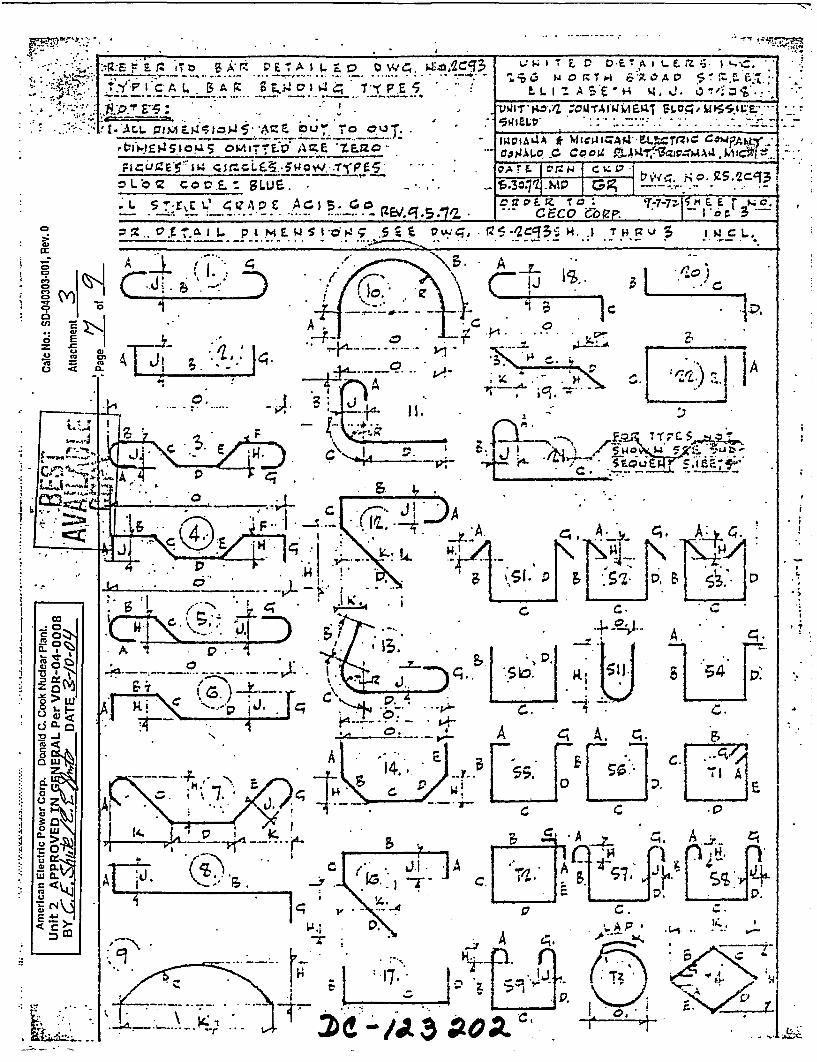
9 Drawing No. DC-123202, "Unit 2 Containment Bldg. Missile Rev.0- A22. Shield, Standard rebar bending details" (Attachment #3)10 Drawing No. DC-123203, "Unit 2 Containment Bldg. Missile Rev. 0 1
App. Shield, Bent rebar list" (Attachment #3)11 Drawing No. DC-123204, "Unit 1 Containment Bldg. Missile Rev. 0 E] E
App. Shield, Straight rebar list" (Attachment #3) _ _12 Ref. NRC Letter N2003014, "Regarding Containment Structure 03/21/03 1 El
Conformance to Design and Licensing Basis"13 Ref. AEP Letter AEP:NRC:4520, "Withdrawal of License Amendment 03/02/04 1 1 -
Request to Use Yield Strength Determined From Measured MaterialProperties for Reinforcing Bar in Structural Calculations for Control
_ _ Rod Drive Missile Shield" ___14 Ref. ASCE Journal of the Structural Division "Variability of Mechanical May, i 1 Li
Properties of Reinforcing Bars" (Attachment #4) 197915 App. Drawing No. 1-2-3186C, Containment Building Missile Shield Plan Rev. 13 E 9 l
& Sections Masonry"16 App. Drawing No. 1-2-3186N, "Containment Building Missile shield Rev. 0 El
Cover Sections and Details Reinforcing"17 App. Drawing No. 1-2-3186P, "Containment Building Missile Shield Rev. 8 1J El 7
Misc. Steel Frames & Details Masonry" _____
18 Ref. ASTM A615-68, "Deformed Billet-Steel Bars for Concrete 1968 Li 1Reinforcment"
19 Ref. DCC-CE-107-QCS, "Reinforcing Steel Specifications" Rev. 3, 1 3I 03/26/69
20 Ref. ACI Standard 318-99 1999 _The above applicable references have been reviewed for pending changes in DOCUMENTUM and for pendingcondition reports in ECAP. Nothing was uncovered in these reviews that would impact this calculation.
This form is derived from 12.EHP-5040-DES-003, Cslculations

Calculation No. SD-040303-001Rev. 0Page 9
6.0 Methodology
As shown in Section 4.0, there is available data for yield points on the rebar that wasinstalled in the missile shields. This data includes the CMTR values from the rebarmanufacturer and includes the I&M site acceptance tests. The CMTR values will not beused in this calculation. The justification for excluding the CMTR values is given inSection 8.0 of this calculation, "Assumptions and Limitations".
This calculation will consider the 14 data points from the I&M site acceptance tests.These 14 data points will first be tested for normality to determine if these data pointsapproximate a normal distribution. The statistical test used for the testing for normality islisted below.
Following the statistical tests for normality, the I&M acceptance test data will beevaluated by performing either numerical review or statistical manipulations of the dataand the results of this evaluation will determine a value for the rebar yield point that isboth appropriate and conservative to be used in the structural calculation for the missileshields (SD-010307-001, See Reference 1). The numerical review of the data is listedbelow as Method 1 and the statistical manipulations of the data to be performed are listedbelow as Methods 2 and 3.
All statistical manipulations will be performed utilizing the statistical analysis toolsavailable in Microsoft Excel (Office 97 and/or Office 2000).
6.1 Testing the data for Normality.
The I&M acceptance test data will be first tested for normality to determine if the 14points of data approximate a normal distribution. Several textbook methods for goodness-of-fit tests such as the Chi Squared Test; the Least Squares Fit using the associatedCorrelation Coefficient, the Kolmogorav-Smirnov Test, and the Anderson-Darling Testwere considered and ruled out because of the small sample size of 14 data points. Thefollowing goodness-of-fit test was identified to be appropriate for use in verifying theassumption that I&M test data points approximate a normal distribution. The goodness-of-fit test chosen was the W-Test. As a complementary check of the results obtained fromthe W-Test, the I&M acceptance test data was evaluated for goodness-of-fit to a betadistribution.
* W-Test
The W-Test is a goodness-of-fit test that is described on Pages 7-9 through 7-12of Reference 3 and is not repeated here.

Calculation No. SD-040303-001Rev. 0
Page 10
Beta Distribution
Through a statistical software product, Crystal Ball 2000, the I&M acceptance testdata was evaluated for goodness-of-fit to a beta distribution. Crystal Ball is not aQA approved software product for use at Cook Nuclear Plant. Therefore, theresults from a Crystal Ball statistical analysis cannot be used in making a designbasis or licensing basis decision. It can be used as a complementary check of theresults obtained from the W-Test.
6.2 Evaluation of I&M Acceptable Test Data
Three methods will be considered in determining the appropriate rebar yield point.
Method 1
Method 1 will consist of a numerical review of the I&M acceptance test data andselection of the lowest yield strength value from any of the individual data points.
The following Methods 2 & 3 will consider combinations of the I&M site acceptancedata points. As determined in Section 9.0, these values approximate a normal distribution.Following on Page 11 is a graphic illustration of a normal distribution. The mean andstandard deviations will be calculated per Reference 3 and, per Page 5-20 of Reference 3,(n-1) will be used in the formula for standard deviation since the mean value is notknown and has to be calculated. Table T-1 lb of Reference 3 will be used to determine thelower interval that contains 95% of the population with 95% confidence. Refer to Section8.3 of Assumptions and Limitations for the justification for use of the 95/95 tolerancelimit.
Following is a list of the definition of terms and of the formulas to be used in Methods2 & 3 to calculate average value, standard deviation, and the lower rebar yield strengthof the rebar population.
n = number of samples involved in the calculationAverage = X _ the sample mean = (summation of all samples)/n
(Reference 3, Page 5-4)
SDEV= . E(Each Sample-X) 2
n-i(Reference 3, Page 5-20)
K = A One-sided tolerance limit factor for a normal distribution given in Table T-1 lb ofReference 3 ). Values will be used for 0.95 confidence level for 0.95 of thepopulation.
The lower interval of a population = X - (K*SDEV)

Normal Frequency Distribution Curve
SDEV = Standard Deviation
Calculation No. SD-040303-001, Rev. 0 Page 11

Calculation No. SD-040303-001Rev. 0Page 12
Method 2
Method 2 considers the 14 I&M site acceptance test data points. Using the formulaslisted above, the mean (average) and standard deviation is calculated for the 14 datapoints and one-sided tolerance limits are developed using Table T-1 lb of Reference 3 todetermine the lower interval rebar yield point that contains 95% of the population with95% confidence.
Method 3
Method 3 will split the I&M site acceptance test data points between Unit 1 & 2. Sincetwo points of the 14 data points are common to both Units 1 & 2, Unit I will consider 6data points and Unit 2 will consider 10 data points. Each of the Unit 1 & 2 data pointswill be analyzed as outlined in Method 2 using the formulas listed above.
7.0 Acceptance Criteria
There are no acceptance criteria associated with this calculation since its purpose is todetermine an appropriate/conservative rebar yield strength value from rebar test data.
- Calculation No. SD-040303-001Rev. 0Page 13
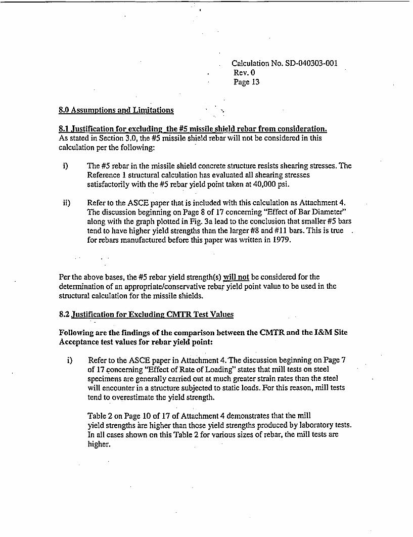
8.0 Assumptions and Limitations
8.1 Justification for excluding the #5 missile shield rebar from consideration.As stated in Section 3.0, the #5 missile shield rebar will not be considered in thiscalculation per the following:
i) The #5 rebar in the missile shield concrete structure resists shearing stresses. TheReference 1 structural calculation has evaluated all shearing stressessatisfactorily with the #5 rebar yield point taken at 40,000 psi.
ii) Refer to the ASCE paper that is included with this calculation as Attachment 4.The discussion beginning on Page 8 of 17 concerning "Effect of Bar Diameter"along with the graph plotted in Fig. 3a lead to the conclusion that smaller #5 barstend to have higher yield strengths than the larger #8 and #11 bars. This is truefor rebars manufactured before this paper was written in 1979.
Per the above bases, the #5 rebar yield strength(s) will not be considered for thedetermination of an appropriate/conservative rebar yield point value to be used in thestructural calculation for the missile shields.
8.2 Justification for Excluding CMTR Test Values
Following are the findings of the comparison between the CMTR and the I&M SiteAcceptance test values for rebar yield point:
i) Refer to the ASCE paper in Attachment 4.The discussion beginning on Page 7of 17 concerning "Effect of Rate of Loading" states that mill tests on steelspecimens are generally carried out at much greater strain rates than the steelwill encounter in a structure subjected to static loads. For this reason, mill teststend to overestimate the yield strength.
Table 2 on Page 10 of 17 of Attachment 4 demonstrates that the millyield strengths are higher than those yield strengths produced by laboratory tests.In all cases shown on this Table 2 for various sizes of rebar, the mill tests arehigher.

Calculation No. SD-040303-001Rev.0Page 14
The CMTR test values and the I&M acceptance test values for yieldpoint given in Sections 4.1 and 4.2 on Page 5 shows that for each individual heatnumber, the CMTR test value for yield point is higher that the I&M value in allcases except one. For Heat No. B37340, one of the I&M test values was higherthan the CMTR test value. The other I&M test value for Heat No. B37340 wasless than the CMTR value. Therefore, thirteen out of the fourteen I&Mtest values for the various heat numbers were lower than the CMTR values.This finding agrees with the statement in Attachment 4 which is the mill testsfor rebar yield strength are generally higher than lab test values for rebarsmanufactured before 1979.
ii) A review of the CMTR test results and the I&M site acceptance test results foryield point on Page 5 shows the following information:
CMTR testsMaximum Value = 57,468 psiMinimum Value = 50,641 psiRange = 6,827 psi
I&M site acceptance testsMaximum Value = 52,692 psiMinimum Value = 49,487 psiRange = 3,205 psi
The above review indicates that the I&M site acceptance test values with anarrower range are grouped closer to the mean or average value of the testvalues. Therefore, the I&M test values consisting of 14 data points have lessscatter than do the CMTR test values.
Summary of comparison of CMTR Test Values and I&M Site Acceptance TestValues for Rebar Yield Point.CMTR values tend to be an overestimation of the yield point according to the ASCEpaper in Attachment 4. The 14 I&M site test values for yield point tend to be groupedcloser to the mean or average value of the test values. Therefore, per engineeringjudgement, the 14 I&M site acceptance test values are judged as being morerepresentative test values to be used in the determination of an appropriate/conservativevalue for the yield point of rebar to be used in the structural calculation for the missileshields.
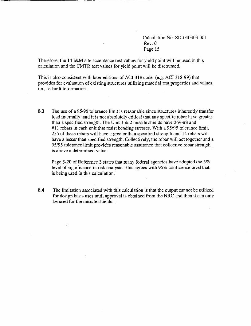
Calculation No. SD-040303-001Rev. 0Page 15
Therefore, the 14 I&M site acceptance test values for yield point will be used in thiscalculation and the CMTR test values for yield point will be discounted.
This is also consistent with later editions of ACI-318 code (e.g. ACI 318-99) thatprovides for evaluation of existing structures utilizing material test properties and values,i.e., as-built information.
8.3 The use of a 95/95 tolerance limit is reasonable since structures inherently transferload internally, and it is not absolutely critical that any specific rebar have greaterthan a specified strength. The Unit 1 & 2 missile shields have 269-#8 and#11 rebars in each unit that resist bending stresses. With a 95195 tolerance limit,255 of these rebars will have a greater than specified strength and 14 rebars willhave a lesser than specified strength. Collectively, the rebar will act together and a95/95 tolerance limit provides reasonable assurance that collective rebar strengthis above a determined value.
Page 3-20 of Reference 3 states that many federal agencies have adopted the 5%level of significance in risk analysis. This agrees with 95% confidence level thatis being used in this calculation.
8.4 The limitation associated with this calculation is that the output cannot be utilizedfor design basis uses until approval is obtained from the NRC and then it can onlybe used for the missile shields.

Calculation No. SD-040303-001Rev. 0Page 16
9.0 Calculations
9.1 Perform Statistical Test to Demonstrate that the Results Obtained During theTwo I&M Site Acceptance Tests for Yield Point Provide Data thatApproximates a Normal Distribution, Taking into Consideration the IndividualHeat Numbers.
An inherent assumption concerning the data obtained during I&M site acceptance testsfor yield point (also referred to in this section as sample data) was whether or not the dataapproximated a normal distribution with reasonable confidence that the sample data isrepresentative of the population. Verification of this assumption was essential in order tohave assurance that the results obtained by methods 2 and 3 were reasonable. Thissection provides verification of this assumption.
Attachment 4, ASCE Journal of the Structural Division, "Variability of MechanicalProperties of Reinforcing Bars", suggests that yield test strength data is representative ofa normal distribution (pages 4 and 5 attachment 4). Based on this recommendation, itwas decided that Unit I & 2 sample data was evaluated for goodness-of-fit to a normaldistribution.
There are several textbook methods (i.e., goodness-of-fit tests) for establishing whetheror not a set of sample data approximates a given distribution. The most commonly usedmethod is the Chi Squared test. However, there was not enough sample data toaccurately perform and use the results of this test. Other goodness-of-fit tests such as, theLeast Squares Fit using the associated Correlation Coefficient, Kolmogorov-Smirnov andAnderson-Darling were also ruled out for the same reasons. A literature search ongoodness-of-fit tests was performed and the following tests were identified to beappropriate considering the sample size of the data and the simplicity of the goodness-of-fit techniques.:The goodness-of-fit test selected to verify the assumption that the sampledata approximates a normal distribution is the W- Test.
An observation concerning the I&M site acceptance test sample data. Although thesample data is small, the data has been determined to be representative of the heat and themanufacturing process used to fabricate the rebar. Additionally, the sample data isbelieved to be a random; unbiased sample of the rebar due to the requirements placed onthe manufacturer in providing rebar for the I&M acceptance tests and the methods used toselect samples of rebar and perform the I&M site acceptance tests.

Calculation No. SD-040303-001Rev. 0Page 17
W-Test
The W-test is a goodness-of-fit test described in reference 3 ("Applying Statistics",NUREG-1475). NUREG-1475 provides a step-by-step approach for performing this test.This step-by-step approach was applied using the data obtained during I&M siteacceptance tests for yield point. The results obtained by using this techniquesubstantiate that the data obtained from the I&M site acceptance tests for yield point forboth Units 1 & 2 and for each of the Units, individually, approximate a normaldistribution. The results are shown on pages 2 thru 4 of Attachment 10. The W-test isdescribed in detail in NUREG-1475, therefore, a description of the test is not provided.
Beta Distribution
Attachment 4, ASCE Journal of the Structural Division, "Variability of MechanicalProperties of Reinforcing Bars", suggests that yield test strength data is alsorepresentative of a beta distribution (pages 4 and 5 attachment 4). Based on thisrecommendation, the Unit 1 & 2 sample data was evaluated for goodness-of-fit to a betadistribution. If the results of the goodness-of-fit tests are satisfactory, then the 95% lowerconfidence bound could be used to provide a complementary check on the results ofmethods 2 and 3.
However, it is difficult to ascertain appropriate alpha and beta parameters to analyze thesample data with respect to the Beta distribution. This is especially true of small samplesizes. Therefore, a statistical software product, Crystal Ball 2000, was used for theseanalyses. Although the primary purpose of Crystal Ball 2000 is to perform Monte Carlosimulations, it also provides for distribution fitting and a host of other common statisticalfunctions and methods. Crystal Ball 2000 is a commercial software application and thesoftware is classified under CNP software control process as "No Risk" (formerly"exempt"). The results obtained by using the software cannot be used for making adesign basis or licensing basis decision, but the results can be used to provide acomplementary check of the methods and results that are used for making thesedecisions.
The methods employed by the software are documented in the user manual, and a step-by-step process for performing statistical goodness-of-fit tests, along with explanationsand acceptance criteria are also provided in the manual. This allows for independentverification of the results obtained by Crystal Ball 2000. Given the caveats andunderstanding of the discussion above, the process to determine a goodness-of-fit to abeta distribution using the sample data and the results obtained using Crystal Ball 2000are described below.

Calculation No. SD-040303-001Rev. 0Page 18
Chapter 3 of the Crystal Ball 2000 software manual provides an easy to follow processfor using the distribution fitting feature. A summary of that process, the sample data used,and the results are provided below.
The 14 data points obtained during I&M site acceptance tests for yield point strength forUnits 1 and 2 and used in this analysis are listed below.
Unit 1 & 2 YieldPoint Strength
49,48749,93550,19250,38450,44850,75950,83350,89751,025 -51,26552,11552,11552,17952,692
The average of the sample data was computed to use as a surrogate assumption. This isnot used in this process; however, a separate value is required by Crystal Ball 2000 fordefining an assumption.
CELL was selected in Crystal Ball 2000 menu and DEFINE ASSUMPTION was selectedfrom the pull down menu. The Beta distribution was then selected from the DistributionGallery provided in Crystal Ball 2000. FIT was then selected from the DistributionGallery to get the Fit Distribution menu.
Active Worksheet was selected in the Fit Distribution menu and the cell ranges from theworksheet containing the above sample data were entered into the Range.
Beta Distribution was chosen in the Fit Distribution 2 menu and Chi-Square Test wasalso selected. The check box for Show Comparison Chart and Goodness-of-Fit Statisticswas checked.

Calculation No. SD-040303-001Rev. 0Page 19
The OK button was selected and the results of the Chi-Square goodness-of-fit test weredisplayed. The results indicated, ** Insufficient Data for Chi-Square Test**.
This process was repeated for the Kolmogorov-Smirnov test and the Anderson DarlingTest. The results for the Kolmogorov-Smirnov test indicated that the data was not a goodfit. According to the Crystal Ball 2000 manual a value less than 0.03 indicates a close fit,the result using the sample data was 0.1614. The results for the Anderson-Darling testdid indicate a close goodness-of-fit, again using the criteria provided in theCrystal Ball manual. The criteria provided states, "Generally a value less then 1.5indicates a close fit. The value obtained for the Anderson-Darling test using the sampledata was 0.3389.
Since the Anderson-Darling is more appropriate for goodness-of-fit tests at the extremetails of the distribution and since this calculation is attempting to determine a minimumvalue, it was believed to be appropriate to consider the results of the Anderson-Darlingtest as reasonable evidence of the goodness-of-fit of the sample data to a betadistribution.
The ACCEPT button in Crystal Ball 2000 menu was then selected. Crystal Ball 2000then presents a window of the frequency chart depicting the sample data in a betadistribution and several parameters of the distribution.
To correspond with the 95/95 confidence intervals used in methods 2 and 3, the PARMbutton in the window was selected and the parameters displayed were changed to matchthe 95% confidence interval. The three parameters input into the Choose CustomParameters window were, 2.5, 50 and 95 for the ['S, 2nd and 3rd parameters, respectively.The 15' parameter, 2.5, represents the lower bound of the 95 percent confidence interval,the 3rd parameter. For the second parameter, a value of 50 was chosen since thisrepresents the median value.
The results provided in Crystal Ball 2000 for the 95% confidence intervals and themedian values are provided below.
Crystal Ball Results of BetaDistribution for the Sample Data
95% lower 49156Median (50%) 51027
95% upper 52574

Calculation No. SD-040303-001Rev. 0Page 20
The results obtained correspond very closely to the results obtained by methods 1, 2and 3. Although the results do not provide for a definitive design basis conclusion,the results do provide a complementary validation of the results obtained bymethods 2 and 3.
Based on the results obtained by the W-Test discussed above, the sample datarepresenting the results of the I&M site acceptance tests for yield point wereconfirmed to approximate a normal distribution.
9.2 Perform the numerical review and/or the statistical manipulations of the 14points of I&M Site Acceptance Data to Determine an appropriate/conservativerebar vield point value for the missile shields.
Method 1
Method 1 consists of a numerical review of the I&M acceptance data and selection of thelowest yield strength value from any of the individual data points. The individual datapoints for yield strength for I&M site acceptance tests are summarized below:
I&M site acceptance tests for yield point and tensile strength of the rebar. Twoindividual tests were performed at the Cook Plant site for each individual heat of steel.
Heat No. Bar Size Unit Yield Point YieldPoint Tensile TensileTest #1 Test #2 Strength Strength
(psi) (psi) Test #1 Test #2. . (psi) (psi)
C34105 #11 1 50,897 52,115 84,679 84,743B37160 #11 1 51,025 50,833 85,320 82,948C35157 #8 1 & 2 51,265 50,759 81,645 82,278B36171 #11 2 52,115 52,692 88,717 91,730A37151 #11 2 50,448 50,192 80,961 81,282B37340 #11 2 52,179 49,487 87,948 80,256A36334 #11 2 50,384 49,935 82,307 83,589
By inspection, the lowest value from any yield point test is 49,487 psi. Therefore,Method 1 suggests using a rebar strength value of 49,487 psi.

Calculation No. SD-040303-001Rev. 0
Page 21
Method 2
Method 2 considers I&M site acceptance data for both Unit 1 & 2. There will be a total of14 data points for both units. As determined previously, this data approximates a normaldistribution. The mean and standard deviation for each population will be calculated perExcel spreadsheets. The Excel spreadsheets and cell formulas will be attached to thiscalculation as Attachment 9.
The list of the definition of terms and of the formulas to be used in Methods 2 & 3 tocalculate average value, standard deviation, and the lower rebar yield strength of therebar population is shown in Section 6.2 on Page 10. For convenience, these terms andformulas are repeated below.n = number of samples involved in the calculationAverage = X = the sample mean = (summation of all samples)/n
(Reference 3, Page 5-4)
SDEV = E (Each Sample -X)2
n-l
(Reference 3, Page 5-20)K = A One-sided tolerance limit factor for a normal distribution given in Table T-1 lb of
Reference 3 ). Values will be used for 0.95 confidence level for 0.95 of thepopulation.
The lower interval of a population = X - (K*SDEV)
Table M2 (Units I & 2)
Yield Yield. Point PointHeat No. Bar Sze Test #1 Test #2
________ _________ - (psi) (psi)
C34105 #11 50,897 52,115B37160 #11 51,025 50,833C35157 #8 51,265 50,759B36171 #11 52,115 52,692A37151 #11 50,448 50,192B37340 #11 52,179 49,487A36334 #11 50,384 49,935
Average 51,023Standard Deviation 947.04

Calculation No. SD-040303-001Rev. 0Page 22
K = 2.614Min Yield Stress = 51,023 -(2.614*947.04) = 48,547 psi
With 95% confidence, the interval of 48,547 psi to infinity contains 95% of thepopulation.
Therefore, Method 2 suggests using a rebar strength of 48,547 psi.
Method 3
Method 3 will split the I&M site acceptance test data between Unit 1 & 2. Since twopoints of data are points common to both Units 1 & 2, Unit 1 will consider 6 data pointsand Unit 2 will consider 10 data points. Each of the Unit 1 & 2 data points will beanalyzed as outlined in Method 2.
Unit 1 Data
Table M3-1
I&M I&MDetermined Determined
Bar Yield Point, Yield Point,Heat Size psipsiC34105 #11 50,897 52,115B37160 #11 51,025 50.833
C351 57 #8 51,265 50,759
_ AVG 51,149= SDEV 505.46
Average = X = 51,149 psiSDEV = 505.46K = 3.708Min Yield Stress = 51,149 -(3.708*505.46) = 49,275 psi

Calculation No. SD-040303-001Rev. 0Page 23
With 95% confidence, the interval of 49,275 psi to infinity contains 95% of thepopulation.
Unit 2 Data
Table M3-2
I&M I&MDetermined DeterminedYield Point. Yield Point,
Heat Bar Size psi
C35157 #8 51,265 50,759
B36171 #11 52,115 52,692
A37151 #11 50,448 50,192
B37340 #11 52,179 49,487
A36334 #11 50,384 49,935
AVG 50,946
SDEV 1072.65
Average = X = 50,946 psiSDEV = 1072.65K=2.911Min Yield Stress = 50,946 -(2.911*1,072.65) = 47,824 psi
With 95% confidence, the interval of 47,824 psi to infinity contains 95% of thepopulation.
Therefore, Method 3 suggests using a rebar strength of 47,824 psi.
Calculation No. SD-040303-001Rev. 0Page 24
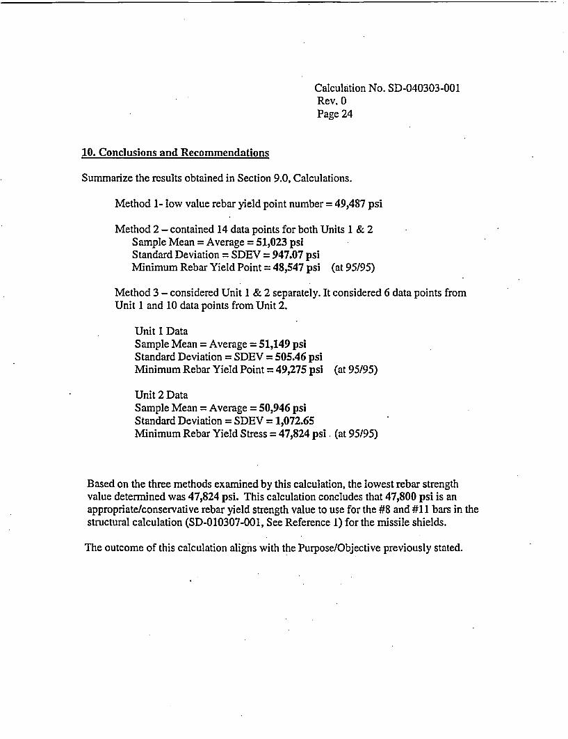
10. Conclusions and Recommendations
Summarize the results obtained in Section 9.0, Calculations.
Method 1- low value rebar yield point number = 49,487 psi
Method 2 - contained 14 data points for both Units 1 & 2Sample Mean = Average = 51,023 psiStandard Deviation = SDEV = 947.07 psiMinimum Rebar Yield Point = 48,547 psi (at 95/95)
Method 3 - considered Unit I & 2 separately. It considered 6 data points fromUnit 1 and 10 data points from Unit 2.
Unit 1 DataSample Mean = Average = 51,149 psiStandard Deviation = SDEV = 505.46 psiMinimum Rebar Yield Point = 49,275 psi (at 95/95)
Unit 2 DataSample Mean = Average = 50,946 psiStandard Deviation = SDEV = 1,072.65Minimum Rebar Yield Stress = 47,824 psi (at 95/95)
Based on the three methods examined by this calculation, the lowest rebar strengthvalue determined was 47,824 psi. This calculation concludes that 47,800 psi is anappropriate/conservative rebar yield strength value to use for the #8 and #11 bars in thestructural calculation (SD-010307-001, See Reference 1) for the missile shields.
The outcome of this calculation aligns with the Purpose/Objective previously stated.
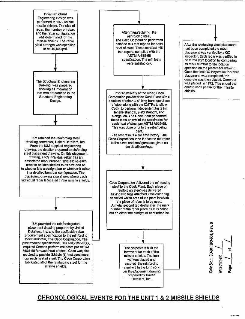
Initial StructuralEngineering Design wasperformed in 1972 for the
missile shields. The size ofrebar, the number of rebar,and the rebar configuration
was determined for themissile shields. The rebar
yield strength was specifiedto be 40,000 psi.
After manufacturing thereinforcing steel,
The Ceco Corporation performedcertified mill test reports for eachheat of steel. These certified mill
test reports complied with theASTM A-615-68
specification. The mill testswere satisfactory.
The Structural EngineeringDrawing was preparedshowing all Information
that was determined In theStructural Engineering
Design.
Prior to delivery of the rebar, CecoCorporation provided the Cook Plant with 6sections of rebar 3 -0" long from each heat
of steel along with the CMTRs to allowCook to perform independent tests for
tensile strength, yield strength, andelongation. The Cook Plant performed
these tests on two of the specimens foreach heat of steel per ASTM A615-68.This was done prior to the rebar being
bent.The test results were satisfactory. The
Ceco Corporation then fabricated the rebarto the sizes and configurations given on
the detail drawings.
.
I&M retained the reinforcing steeldetailing contractor, United Detailers, Inc.
From the I&M supplied engineeringdrawing, the detailer prepared a reinforcingsteel placement drawing. On this placement
drawing, each Individual rebar has anassociated mark number. This allows eachrebar to be identified as to Its size and as
to whether it Is a straight bar or whether It existsIn a detailed bent bar configuration. The
placement drawing also shows where eachIndividual rebar Is located in the missile shields.
4
After the reinforcing steel placementhad been completed,the rebarplacement was verified by a QCInspector. Each rebar was verified tobe in the right location by comparingIts mark number to the locationspecified on the placement drawing.Once the final 00 Inspection for rebarplacement was completed, theconcrete was then placed. Concretewas placed In 1972. This ended theconstruction phase for the missileshields.
a)
A,c-Ic
o
C3 C
C. E3 LD Wn
O Zs cc
Ceco Corporation delivered the reinforcingsteel to the Cook Plant. Each piece of
reinforcing steel was deliveredhaving two tags attached. One color tagspecified which area of the plant in which
the piece of rebar Is to be used.A metal second tag designates the marknumber of the rebar piece as It is called
out on either the straight or bent rebar list.
I&M provided the reinforcing steelplacement drawing prepared by UnitedDetailers, Inc. and the applicable rebar
procurement specification to the reinforcingsteel fabricator, The Ceco Corporation. The
procurement specification, DCC-CE-1 07-OCS,required Ceco to perform mill tests per ASTMA615.68 for each heat of steel. Ceco was alsorequired to provide l&M six (6) test specimensfrom each heat of steel. The Ceco Corporation
fabricated all of the reinforcing steel for themissile shields.
The carpenters built theformwork for each of themissile shields. The Iron
workers placed andsecured the reinforcingsteel within the formwork
per the placement drawingprepared by United
Detailers, Inc.
CHRONOLOGICAL EVENTS FOR THE UNIT 1 & 2 MISSILE SHIELDS

UNIT NO. 1 REACTOR MISSILE SHIELDS
HEAT NO. C34105
Test Data for Heat No. C34105Steel Manufacturer's CMTR data:Yield Point = 53,205 psiTensile Strength = 89,423 psi
I&M Site Bar Test Report:Test No. 1Yield Point = 50,897 psiTensile Strength = 84,679 psi
Test No. 2Yield Point = 52,115 psiTensile strength = 84,743 psi
Drawing Nos. DC-110152 and DC-123206
Reinforcing Steel Included in Heat No. C34105
Rebar Size No. of Rebars Rebar Mark Rebar FunctionDouble 180 degree hook
#11 57 1lB10 bar, top and bottorn,resisting bending stressesDouble 180 degree hook
#11 12 ~l l 1sbar, top, resisting bending______12____ _____ tresses
Double 180 degree hook#11 32 llB 1bar, top and bottoxn,_____32_1_1_resisting bending stresses
Double 180 degree hook
#11 8 1 1B2 bar, top, resisting bending____ ____ ____ ____ ____stresses
Double 180 degree hook~h1 211B21bar, top, resisting bending#11 2l1 lB21 stresses
Calc No.: SD-040303-001, Rev. 0
Attachment _2
Page / of 9

UNIT NO. 1 REACTOR MISSILE SHIELDS
HEAT NO. B37160
Test Data for Heat No. B37160Steel Manufacturer's CMTR data:Yield Point = 54,487 psiTensile Strength = 83,333 psi
I&M Site Bar Test Report:Test No. 1Yield Point = 51,025 psiTensile Strength = 85,320 psi
Test No. 2Yield Point = 50,833 psiTensile strength = 82,948 psi
Drawing Nos. DC-1 10152 and DC-123207
Reinforcing Steel Included in Heat No. B37160
Rebar Size No. of Rebars *Rebar Mark* Rebar FunctionStraight Bar, Top and bottom bars,
#11 64 28'-3" Long resisting bending stressesStraight Bar, Top bars, resisting bending
#116 26'-6" Long stressesStraight Bar, Top bars, resisting bending
#11 4 7'-6" Long stresses
Straight Bar, Top and bottom bars,#11 41 24'-0" Long resisting bending stresses
Straight Bar, Top bars, resisting bending#11 8 22'-3" Long stresses
* Rebar mark numbers are not assigned to straight bars.
Calc No.: SD-040303-001, Rev. 0
Attachment 2Page 2 of

UNIT NO. 1 REACTOR MISSILE SHIELDS
HEAT NO. C35157
Test Data for Heat No. C35157Steel Manufacturer's CMTR data:Yield Point = 57,468 psiTensile Strength = 85,316 psi
I&M Site Bar Test Report:Test No. 1Yield Point = 51,265 psiTensile Strength = 81,645 psi
Test No. 2Yield Point = 50,759 psiTensile strength = 82,278 psi
Drawing Nos. DC-1 10152 and DC-123207
Reinforcing Steel Included in Heat No. C35157
Rebar Size No. of Rebars Rebar Mark* Rebar Function
Straight Bar, Side face bars resisting#8 13 28'-3" Long torsional shear and
shrinkage & temperaturestresses
Straight Bar, Side face bars resisting#8 12 24'-O" Long torsional shear andshrinkage & temperature
. stresses
* Rebar mark numbers are not assigned to straight bars.
Calc No.: SD-040303-001, Rev. 0
Attachment A2
Page 3. of _ _

UNIT NO. 2 REACTOR MISSILE SHIELDS
HEAT NO. B37340
Test Data for Heat No. B37340Steel Manufacturer's CMTR data:Yield Point = 51,602 psiTensile Strength = 83,012 psi
I&M Site Bar Test Report:Test No. 1Yield Point = 52,179 psiTensile Strength = 87,948 psi
Test No. 2Yield Point = 49,487 psiTensile strength = 80,256 psi
Drawing Nos. DC-1 10153, DC-123203, and DC-123204
Reinforcing Steel Included in Heat No. B37340
Rebar Size No. of Rebars Rebar Mark* Rebar FunctionDouble 180 degree hook
#11 57 11BIO bar, top and bottom,resisting bending stresses
Straight Bar, Top and bottom bars,#11 64 28'-3" Long resisting bending stresses
* Rebar mark numbers are not assigned to straight bars.
Calc No.: SD-040303-001, Rev. 0
Attachment 2Page LI of 9-

UNIT NO. 2 REACTOR MISSILE SHIELDS
HEAT NO. A37151
Test Data for Heat No. A37151Steel Manufacturer's CMTR data:Yield Point = 50,641 psiTensile Strength= 84,615 psi
I&M Site Bar Test Report:Test No. 1Yield Point = 50,448 psiTensile Strength = 80,961 psi
Test No.2Yield Point = 50,192 psiTensile strength = 81,282 psi
Drawing Nos. DC-1 10153, DC-123203, and DC-123204
Reinforcing Steel Included in Heat No. A37151
Rebar Size *No. of Rebars Rebar Mark* Rebar FunctionDouble 180 degree hook
#M1112 lBiI 1 1bar, top, resisting bending_ _ _ _ _ _ _ _ _ _ _ _stresses
Straight Bar, Top bars, resisting bending#11 16 26'-6" Long stresses
_ __ I _ __ I __ I __
+ 4- 1
+ 4- 4
+ 4* I
J. J
* Rebar mark numbers are not assigned to straight bars.
Calc No.: SD-040303-001, Rev. 0
Attachment 2Page k of q

UNIT NO. 2 REACTOR MISSILE SHIELDS
HEAT NO. A36334
Test Data for Heat No. A36334Steel Manufacturer's CMTR data:Yield Point = 55,769 psiTensile Strength = 85,576 psi
I&M Site Bar Test Report:Test No. 1Yield Point = 50,384 psiTensile Strength = 82,307 psi
Test No. 2Yield Point = 49,935 psiTensile strength = 83,589 psi
Drawing Nos. DC-1 10153, DC-123203, and DC-123204
Reinforcing Steel Included in Heat No. A36334
Rebar Size No. of Rebars Rebar Mark* Rebar FunctionDouble 180 degree hook
#11 32 11 B 1 bar, top, resisting bendingstresses
Straight Bars, Side face bars resisting#11 41 24'-0" Long torsional shear and
shrinkage & temperaturestresses
* Rebar mark numbers are not assigned to straight bars.
Calc No.: SD-040303-001, Rev. 0
Attachment 2Page ( of 7

---------
UNIT NO. 2 REACTOR MISSILE SHIELDS
HEAT NO. B36171
Test Data for Heat No. B36171Steel Manufacturer's CMTR data:Yield Point = 54,487 psiTensile Strength = 89,423 psi
I&M Site Bar Test Report:Test No. 1Yield Point = 52,115 psiTensile Strength = 88,717 psi
Test No. 2Yield Point = 52,692 psiTensile strength = 91,730 psi
Drawing Nos. DC-1 10153, DC-123203, and DC-123204
Reinforcing Steel Included in Heat No. B36171
Rebar Size No. of Rebars Rebar Mark* Rebar FunctionDouble 180 degree hook
#11 8 1 1B2 bar, top, resisting bendingstressesDouble 180 degree hook
#12 1B1bar, top, resisting bending#11B21 stresses
Straight Bar, Top bars, resisting bending#11 4 7'-6" long stresses
Straight Bar, Top bars, resisting bending#11 8 22'-3" Long stresses
* Rebar mark numbers are not assigned to straight bars.
Ca:,. No.: SD-040303O001. Retv. 0
Attachment aPale C, of F

I
UNIT NO. 2 REACTOR MISSILE SHIELDS
HEAT NO. C35157
Test Data for Heat No. C35157Steel Manufacturer's CMTR data:Yield Point = 57,468 psiTensile Strength = 85,316 psi
I&M Site Bar Test Report:Test No. 1Yield Point = 51,265 psiTensile Strength = 81,645 psi
Test No. 2Yield Point = 50,759 psiTensile strength = 82,278 psi
Drawing Nos. DC-110153 and DC-123204
Reinforcing Steel Included in Heat No. C35157
Rebar Size No. of Rebars Rebar Mark* Rebar Function
Straight Bar, Side face bars resisting#8 13 28'-3" Long torsional shear and
shrinkage & temperaturestresses
Straight Bar, Side face bars resisting#8 12 24'-0" Long torsional shear and
shrinkage & temperature._ stresses
* Rebar mark numbers are not assigned to straight bars.
Cal: No.: SO-040303-01, Rev.0
Attachmrent ?Page L of ___

Reinforcing Steel Placement Drawings
1.)
2.)
3.)
4.)
5.)
6.)
7.)
8.)
Drawing No. DC-1 10152, "Unit 1 Containment Bldg. Missile Shield, Rebarplacement drawing"Drawing No. DC-123205, "Unit 1 Containment Bldg. Missile Shield, Standardrebar bending details"Drawing No. DC-123206, "Unit I Containment Bldg. Missile Shield, Bent rebarlist"Drawing No. DC-123207, "Unit 1 Containment Bldg. Missile Shield, Straightrebar list"Drawing No. DC-1 10153, "Unit 2 Containment Bldg. Missile Shield, Rebarplacement drawing"Drawing No. DC-123202, "Unit 2 Containment Bldg. Missile Shield, Standardrebar bending details"Drawing No. DC-123203, "Unit 2 Containment Bldg. Missile Shield, Bent rebarlist"Drawing No. DC-123204, "Unit 1 Containment Bldg. Missile Shield, Straightrebar list"
Calc No.: SD-040303-001, Rev. 0
Attachment 3Page L of

THIS PAGE IS ANOVERSIZED DRAWING OR
FIGURE,
. . ,I
I . _
; - : .
... I
.. ;I
THAT CAN BE VIEWED AT THERECORD TITLED:
DWG.1C93"UNIT'NO.1 CONTAINMENT BLDG
MISSILE SHIELD."
WITHIN THIS PACKAGE..OR BY SEARCHING USING
DWG. NO. 1C93.
D-01

" * . .vl* ;a w *'-*
; . ;-i - ;5r p> ,4 ~ M ;; AsLH:9 i 1...-*:. - r j
._., _____. ____________* _* _* ___2 ____* _____lb*
,v .S4A hf91 - ,A ,c~ro; Co,'TS,4-._, ,; ,-rar;7 5,,j>> ji,~;E,,,>s ~i nir > 9 g .c :-0 A~ul,:k~wA~t-, >;v14 (
; * 4~~~~~~~~~~~~~~~i -;r.4. >;i 5. ;.S v . £ 8 a pS . _ '
> L o~~~~~~~~~~~~~~~~I~S7 .:!>-§g ipg';i;{-*/'x8'S .. .,k f .;.-";- I
Lji -. *E 7--, q .is;pD .RC I I * . . -_ : ;
C)
I:.
-3 _ _ - '
* * 1.. .
- . ' . : s .
* Eza L
o .
01~~4 :-r4S.S
M:~~vi Alf=C, ''$ ,
*11<1
* - / ;~ i; \ ' -- i 4 .5 - K - ; W in S
_ *.
~ .~ * *S IC .
4 4 . . 4
.........
.. l
4t- -1
I . *U
It
1
, L
. .L

If
iCaic No.: SD-041)303-001, Rev. 0
IAtichn.ent 3.4 of _

Czii No.: SD.040303-001, Rev. A
Atachmint '
Page _ of 7

THIS PAGE IS ANOVERSIZED DRAWING OR
FIGURE,
THAT CAN BE VIEWED AT THERECORD TITLED:
DWG.2C93"UNIT NO.2 CONTAINMENT BLDG
MISSILE SHIELD."
WITHIN THIS PACKAGE..OR BY SEARCHING USING
DWG. NO. 2C93.
D-02
AZ *.-- ,, t E ,% rT z Lk A r P E' A I . 0f c V. Cj. a.,ZIC'q
;' I> C' vy A L I Bf A ;6E;CI ;.tPE
t~iME95.10.45 Om)-rrE........ , AI.E '7o........ ..a
. f.
__ ~6414T . _.._.. . - - *. $ 1
,- . f
1, 1 T t X C E T A I L L .M- }W<4 ) aot T i7 Z - A PS
1 eL I - -I- -
oIIL~A, * MIiJB^AM =4.rfsc Caws,;-CJ; C. CociM SEAgL.',A:¢MAi4 .MjI&-
. .
I . ."
CPA r L I rr0 N C U: f7 1 >V .o. R 5.2 C°13
= :Z.. Vt ,, a I L. p I m E, w S I -c pi % .5 £E £ vw , .5 ac *cqic H, . r U Rz v_. _ -_ .*- - -_ * * * _ ._ .* -- _ *- * *- * *_* -_ *-_ * - .
IiI
I i~ o .
1 C.
-d
!. c ; . .9- I LY C.,

I
BAR :o T.
.pp -4 -, :M v f r ?£~~- .. ,.|_ _. .t_ _ .,
' '7- p " '' z.,M. I . w. baT: .'LP
ZSTA I SM 9W.:.v ksj
t..., - , . -._
a=VC2Cr-*;li.C A;
. .- .L ; . 6-
*1.
._ . :, .
sS:*'-'- . \, *... . . .
v .
4e : it
-ti , .
-;sE_ . , .
'', .esZ;=
,4S_. . .-
iod v 3 . j P1I I . . . : - ... . -. _, Jog0i- Il 4,;5 1. KG I z ,., ,; , .
_ -1 . . ._' _-S~lo., . 2.9-
_-.... .. .
1O' .is 1.;01...,.
-4---C9-
...tL
- ---.
rII
4
._
',.; Calc No.: SD-040303001, Rev. 0
; Attachment 3. Page' : of

D-
to~
. -
z
CL0
':
0 .C,
U
>-
I - "- .-. , ' A. .. ; - e
-6 A R P EA. L. b
5 TA -' A I c,-H -r -F A. R :- .. * ;;z . ,i
*'. ' .;;' ' f.' -' ', ,' E' .'-A ;, -A ' . . .' . ' - 5 7
Al 65 t C t 9 4::^ E Ci . :et5n
u ) I *T E- D V S * A I L E Z J I C./ZjC. korzrT H s.0O A s- .r
E U. I-1 A 6 El T 8N J ,.0 17'70*'r,- ,N th Wt l9Kitb.A-~it£ --w; O . --z MAI'. _ _ . _ . _
_ _ _ _ _ _4 ., .A .F51HJL~_ ro; * 5 : o
F¢ a, : IZ Te5; 5E E g^s¢ ..v.4.-ARW IC5. 5 HF-ET Wo L co04 L; ' c~ !4 ~ . 6o L aL _
.4 . L.F. TN Wp .i E -LE 1. .'r 4
.G 4 u I_ _ _ _ _ _ _ _ _ _ _ _ _ _ . * . :
41 li 24i _ o . : _..
. ii . - 7 /2~ _ _ _ ._ ._._. . _ _ _ _ _ _
A~~~_ ii ___ ___ ___ _
_ _ _ _ _ _ _ _ _ _ _ _ _ _ _ _...._ _ __ '_ _ _ _ _-
3, ZS 3___ . 77J' 1 ,
.,~~~ * , . ...
. . __ _ . . .Calc No.: SD-040303-001, Rev. 0
Attachment 3Page 7 oi I
-* . SAT 11' * - 1 . 4 .' _ _ _ _ _ _
11TA 1SU 1-. I CT; -
.l .
a .' _ _; __ ._ _ _I_ .1 . _-.i
|_ _ :_ _ _ _ _ _ _ _ _ _ ^: ! " . l. .,| i2
._ .,_ ,, _ _ _ ._ . __
_____ __ __ ____._* _ ro rAL S 4T j.k° -3 : 1Tt 4 '
___I_ 11 -___ _ 1_ _ I ___ _ U~ 2I ( ._ __
1 ._ _ _ _ _ .. A 1. .T. .,'_I__ 11 __ I -,~f I. , r^ sr °. 2 1 f i2
_ _ _ I lW; I - t.

SUBSTITUTE ATTACHMENT 4CALCULATION SD-040303-001, REVISION 0
(Replaces a 17 page copyrighted article)
Civil Engineering DatabaseVariability of Mechanical Properties ofReinforcing Barsby Sher Ali Mirza, (Professional Research Assoc., Dept. of Civ. Engrg., Univ.of Alberta, Edmonton, Canada) and James G. MacGregor, Fellow, ASCE,(Prof., Dept. of Civ. Engrg., Univ. of Texas at Austin, Austin, Austin, Tex.; onleave as Prof. of Civ. Engrg., University of Alberta, Edmonton, Canada)
Journal of the Structural Division, Vol. 105, No. 5, May 1979, pp. 921-937
Document Journal Papertype:
Errata: ST May 1980, pg. 1232
Abstract: The results of approximately 4000 published and unpublishedtensile tests on deformed reinforcing bars are studied to obtainstatistical relationships for various mechanical properties. Thesample included No.3 through No.18, Grades 40 and 60, bars.The means and coefficients of variation of the mill test yieldstrengths were found to be 48.8 ksi (337 MN/M2 ) and 10.7% forGrade 40 and 71 ksi (MN/M2) and 9.3% for Grade 60 bars. Betadistributions were used to represent both of these sets of data.The static yield strength was found to be 3.5 ksi (24 MN/M2 ))lower on the average than the mill test yield strength in bothcases, with a coefficient of variation of 13.4%. The trend tolower yield strengths with increased bar sizes observed early inthe 1970's was not present in more recent test data, apparentlydue to more stringent production control in recent years.

CONFIGURATION DOCUMENT IMPACT ASSESSMENT
CDI Number: CDI - Page 1 of 5
INITIATIONDescription of Change Activity:(Describe the reason for the changes. Identify a primary change driver, and include a brief description of the activity.)
The primary change driver is calculation SD-040303-O01 (Reactor Missile Blocks Reinforcing Steel Yield Strength). Rev. 0 This calculationdetermines an appropriate yield strength from rebar CMTR and rebar site acceptance test data, for use in the structural calculation for thecontrol rod drive missile shields (SD-010377-001).
Condition Report 03085024 documents that the NRC (letter dated March 23, 2003) did not accept use of actual rebar yield strength in thestructural calculation (SD-010307-001) for the Control Rod Drive Missile Shield. I&M subsequently submitted a LAR (letter dated November12,2003, AEP:NRC:3520-Ol) to request the use of yield strength from measured material properties, based on CMTR (mill test) data. I&Msubsequently withdrew this LAR. via letter dated March 2, 2003,AEP:NRC:, citing the existence of additional supporting data (I&M rebar siteacceptance test data). Calculation SD-040303-001 uses both CMTR and site acceptance test data to determine an appropriate yield strengthvalue for use in the missile shields and will support a new license amendment request based on consideration of both sets of rebar test data.
CDI Number: CDI - YYYY-NNNNN Rev NN./R N/A - CDI is to be issued closed and attached to a controlled or record document.
Preparer: Paul G. Schoepf
Print Name Sinature / ..Dt
Rvee:Paul W. Leonard > )
050.59 a CDI PSG Print Name Signature /DifJ
CLOSEOUTAll requirements of the implementation plan have been met, and all impacted documents have either been updatedor reference to an appropriate tracking mechanism has been noted. This CDI may be closed out.
Closeout Paul W. LeonardR eview er: . _ _ __ _ _ __ _ _ __ _ _ __ _ _
Print Name Signature
PART 1 - Functional Area (FA) ImpactsCheck 1 and/or 2 as applicable:1. El Impacts and Interfaces are sufficiently addressed and documented in the associated change driver procedure andare not documented here - see Part 2 for Document Impacts.2. 0 The following Functional Areas were assessed, and the results are documented below.
Desiln Enoineerino Config Mgmto Mod Admino l&Co ElectricalO MechanicalED Structural
Plant Engineeringo Productiono Programso SystemSite Protectiono Fire Protection0 Securityfl F-Plan
O Fuel, Safety and Analysisand Reactor Engo Regulatory AffairsO information Technologyo Trainingo Operationso Performance Assurance
El Maintenanceo Testingo Rad/Chemi/Envo Material ManagementO Other (See Below)
FA Assessed BYimpacts CommentsStructural Preparer 1 Yes Calculation SD-010307-001 for the structural qualification
D FA No of the CRDM missile blocks will require revision, following(Name) NRC issuance of a Safety Evaluation Report, to incorporate
the use of measured rebar material properties into thecalculation. Specification ES-CIVIL-0432 (containmentdesign criteria) also requires revision. See below for furtherdiscussion and tracking vehicles. There are no otherspecific impacts for the structural area.
This form is derived from information found in PMP-5043-CDI-001. It or a similar form may be usedprovided the content is consistent with the requirements of that procedure.
Calculation SD-040303-001Rev. 0
Attachment 5, Page I of 5

CONFIGURATION DOCUMENT IMPACT ASSESSMENT
CDI Number: CDI - Page 2 of 5
PART 2 - Document ImpadsReview configuration documents to determine impacts from the activity being performed. NOTE: All impactsmust be found acceptable and either updated concurrently with the impacting activity execution or a tracking mechanism initiated toensure later update.
List Specific Documents/Programs Reviewed/lmpacted Impacted Document UpdateRerer to Figure 2 of PMP-5043-CCD-001 for list of configuration documents. Indicate: FA Conc DateIdentify specific sections impacted. Owner to urren Complete
Notify OR via t or CheckifDocument Upda Tracking Pending
Distribution te? Number rev
la. Drawings S N/A Go A ______
None reviewed. O _ __
_ _ El _ _ Ellb. Vendor Manuals 3 N/A .; 1 ^ s Z G ilNone reviewed. E]L
2. Databases 7 i3NA SiS;vso,- f.I¢ taly4SSw
None reviewed. _ El _ _ ElEl
3. Software 3 N/A : w 4 - _
None reviewed. El
4a. Procedures N/A . _______
None reviewed. El_.r . A
4b. Programs (See Department Websites to help o N/A ElTT . -identify program owners) A *i
None reviewed. D
4c. Calculations E N/A 2* . ____ 4SD-010307-001 Via Document U 030850242 E]
____ Distribution _
4d. Design Standards | N/A ' _____
None reviewed. E] I ElEl _ El
4e. Emergency Plan Info 9 N/A _________ ___ I__,_
None reviewed. J E_ __ E
4f. Specifications E N/A 4 . X ; 1*,;iES-CIVIL-0432-QCN Via Document E 03085024.2 E]
, Distribution I
This form is derived from information found in PMP-5043-CDI-001. It or a similar form may be usedprovided the content is consistent with the requirements of that procedure.
Calculation SD-040303-001Rev. 0
Attachment 5, Page 2 of 5

CONFIGURATION DOCUMENT IMPACT ASSESSMENT
Security Plan - SafeguardsNot reviewed (see discussion 1
Part 3 - For 4g: Identify all electronic files searched, the search parameters used, and discuss theresults.
This form is derived from information found in PMP-5043-CDI-001. It or a similar form may be usedprovided the content is consistent with the requirements of that procedure.
Calculation SD-040303-001Rev. 0
Attachment 5, Page 3 of 5

CONFIGURATION DOCUMENT IMPACT ASSESSMENT
CDI Number: CDI - - Page 4 of 5Operating License and Technical Specifications were reviewed (Unit 1 Rev. 64, Amendment 280 and Unit 2Rev. 68, Amendment 264 in Documentum) using key words "rebar", "reinforcing", "reinforcement", "yieldstrength", "ACI" and "concrete". There were no hits on "rebar", "reinforcing", "reinforcement" or "yieldstrength". Hits on "ACI" had nothing to do with concrete and rebar, and hits on "concrete" had noimplications for rebar yield strength.
UFSAR was searched using keywords words "rebar", "reinforcing", "reinforcement", "yield strength", "ACI"and "concrete"
UFSAR Table 5.2-8 (Containment Internal Structures Element Design Pressures) shows a design pressurecapability for the missile shield of 53.9 psi based on the 2001 reanalysis (which used measured material propertiesof 50.6 ksi for rebar strength). This value will change depending on the final rebar strength determined fromcalculation SD-0403030-001 and its impact on structural calculation SD-010307-001.
UFSAR Section 5.2.2.5 discusses Structural Materials for the containment, and notes that reinforcement steel has aminimum strength of 40,000 psi. This section also notes that stresses in rebar was generally kept to grade 40values. This statement is literally not impacted, however, it should be clarified (once NRC approval is obtained) tonote that stresses above 40,000 psi are only allowed for the missile shields, based on the SER received. Section5.2.2.3 discusses use of capacity reduction or "phi" (0 )factors, which reduce capacity to account for small adversevariations in material strengths (e.g., 0 = 0.90 for flexure). The use of phi factors in structural calculations is notimpacted.
Searched SERs for "rebar" and "reinforcement". SER N69031 (1/14169) includes the text, ""no steelreinforcement will experience average strains beyond the yield point at the factored load." This statement suggeststhat the response of the containment structure, even under the load combination involving the Design BasisEarthquake, will remain elastic and below the yield level." The calculation SD-040303-001 will define a yieldstrength based on test data and the related LAR will request NRC approval for the use of measured materialproperties in structural calculations for the missile shield. There is no intent to have rebar experience strainbeyond yield point. Approval to use measured (vice specified) yield point will be solicited and obtained from theNRC. Therefore, this statement is not impacted.
SER N85078 (2/25/85) regarding Containment Ultimate Capacity includes the text, "The D. C. Cook containmentultimate capacity was initially evaluated by staff's consultant, Gunnar Harsted. The evaluation was based on thecode specified design strengths for concrete, reinforcing steel, liner steel and structural steel, and on simple handcalculation. On the basis of this evaluation it was identified that the containment capacity is limited by the strengthof the equipment hatch closure plate and equipment hatch door, and the limiting internal pressure is 23.5 psig. Anindependent evaluation was made by Structural Mechanics Associates (SMA), the D. C. Cook licensee'sconsultant, and is contained in the two referenced reports. The SMA analyses were based on the "as built"strengths as well as the code specified values and more detailed computer analyses were employed. The "as built"strengths consisted of the lowest sample value and the mean sample value of the materials. Containment internalpressures corresponding to the code specified and "as built" values were calculated for different limiting sectionsof the contaiiitnent. In order to measure the anticipated degree of dispersion in the calculated results, aprobabilistic description of the ultimate internal pressure capacity of the containment was developed. Theevaluation identified four limiting modes of failure. They are shear failure in base mat, membrane hoop tensionfailure of containment cylinder, bending failure of equipment hatch, and bending failure of personnel hatch."This SER acknowledged the'use of "as-built" strength for determination of containment ultimate capacity, andbased on its results, the missile blocks were not limiting components. Since NRC approval is being sought to use"as-built" rebar strength, and the noted SER already acknowledges the use of as-built material properties, this SERis not impacted.
This form is derived from information found in PMP-5043-CDI-001. It or a similar form may be usedprovided the content is consistent with the requirements of that procedure.
Calculation SD-040303-001Rev. 0
Attachment 5, Page 4 of 5

CONFIGURATION DOCUMENT IMPACT ASSESSMENT
CDI Number: CDI - Paze 5 of 5
CMS was searched using key words "rebar", "reinforcing", "reinforcement" and "yield strength". Fivecommitments of some relevance were identified.
8161 - This commitment described that I&M will revise the ice condenser endwall calculation (SD-010307-003)with respect to required rebar yield strength. This commitment was closed (calculation revised and no longerrelies on as-built rebar yield strength). This commitment is closed.
4530- This commitment discusses containment analysis related to hydrogen burn, and discussed consideration ofrebar yielding. There is no specific discussion of rebar yield strength. This commitment is closed/outdated.
4386 and 4566 - These early commitments were for I&M to supply mill test reports of materials and design detailsused for the containment liner and reinforcing bars to Dr. Harstead (Containment Ultimate Capacity analysis).These commitments are closed/outdated.
8202 - This commitment (4/23/03) was for I&M to submit a LAR for use of missile shield reinforcing bar strengthbased on material test data. This commitment was closed based on AEP submitting a LAR on 11/12/03. Thiscommitment needs to be reopened based on I&M's withdrawal of the LAR, or a new commitment generated.
8280- This commitment is for I&M to submit a revised LAR to resolve the missile shield reinforcing bar yieldstrength issue. This calculation supports this commitment.
Final consideration of impacts based on what NRA does regarding commitment 8202. Others are not impacted.
The Environmental Protection Plan and Security Plan were not reviewed. These plans would not contain anydiscussion of rebar strength values used in structural calculations.
Constraints and Implementation Plan: (describe sequence of events for document changesand any restrictions or milestones that apply)
Calculation SD-0403030-001 is being developed to determine an appropriate rebar yield strength value based onmeasured material properties, for use in the structural calculation for the missile shields (SD-010307-001). Thevalue determined in calculation SD-040303-001 will be the basis for a License Amendment Request (LAR) torequest NRC approval to use this value. This LAR is scheduled to be submitted to the NRC by 4/20/04.
Following receipt of an SER from the NRC, the structural calculation SD-010307-001 will be revised toincorporate the yield strength value. The UFSAR will also be changed to note that measured rebar strengthproperties are used for the missile shield only, and the resulting capacity of the missile shield will be added toUFSAR Table 5.2-8. Finally, specification ES-CIVIL-0432-QCN will also be changed to note that measuredrebar strength properties are used for the missile shield only.
In the event the NRC elects NOT to issue an SER allowing the use of measured material properties, an alternateresolution path will be developed. This may include alternate submittal to allow use of a reduced load factor on .pressure, or to re-pour new missile blocks.
This form is derived from information found in PMP-5043-CDI-001. It or a similar form may be usedprovided the content is consistent with the requirements of that procedure.
Calculation SD-040303-001Rev. 0
Attachment 5. Page 5 of 5

AEP DESIGN INFORMATION TRANSMITTAL (DIT)DIT Form, Part 1
Originating Organization
3 SAFETY-RELATED 0 AEP DIT No DIT-B-02851-00
:1NON-SAFETY-RELATED Other(specify)
D.C. Cook Unit (Circle applicable): BOTH Page 1 of 31
System CNTMT To Paul G. SchoepfDesignation
Subject: Summary of Tensile Testing Results for Rebars Used In Control Rod Drive Missile Shields forUnits 1 and 2Satyananda Staff Engineer -- I )Chakrabartl ____ __ __ __ __ __
Preparer Position Prep Signature Date I
Paul W. Leonard Principal Nuclear <U * L.../ (2Specialist
Reviewer Position RIevlbtr's Signature D te
Paul G. Schoepf Manager,StructiMech. Design Bads A d gnat
Approver Position Approvers Signature 'U Date
Status of Information: 0 Approved for Use 0 Unverified
Method and Schedule of Verification for Unverified DITs N/A.
-CR#Holds Associated with Unverified DlTs: N/A.
Descripton of Information: The Information contained In this DIT collates the relevant rebar test data andbackup documents. For details, see Part 2 of this document.
Purpose of Issuance (Including any Precautions or Umitations): To support license amendment request to theNuclear Regulatory Commission on the use of CMTR data In the analyses of the Control Rod DriveMissile Shields In the Containment.Source of Information: The material bar strengths are taken from Concrete-Reinforcement Bar Test Reports
prepared at the time of Initial construction. The copies of test data are attached.Engineering Judgement Used? E Yes 0 No e I
Controlled Reference / Document No.: 1. Calc SD-010307-001 ,,CS-01 (Approved)- 2. NTS-2002-021 -REP. Rev.0 (Approved)
3. DIT.B-01954-0O (Approved)4. UFSAR. Ch. 5, Rev. 18.1 (Approved)
Uncontrolled Reference / Document No.:
Distribution: Copy to Requestor P.G. SchoepfCopy to DIT Administrator FileOriginal to NDM (Transmitted by DIT Administrator)
Calc No.: SD-040303-001, Rev. 0
Attachment 6Page / of 3 J
This form Is derived from the Inforrmation In 12-EHP-5040-DES-001, Rev. 3, Control of Design Input, Data Sheet 3, AEP DesignInformation Transmittais (DIT) - Drr Form

AEP DESIGN INFORMATION TRANSMITTAL (DIT)DIT Form, Part 2
Design Information Transmittal I DIT No. DIT-B-02851 -00 Page 2 of 31
Description of Information(Continued):
The Collation of material test data Is presented in Table 1 below and contains the followingInformation:
1. Unit No.2. Heat No. Calc No.: SD-040303-001, Rev. 03. Bar Size4. Yield Point from Manufacturer Test, psi Attachment 675. Tensile Strength from Manufacturer Test, psi6. Yield Point from l&M Site Bar Test Report, psi Page C a of3/7. Tensile Strength from I&M Site Bar Test Report, psi8. R ce
Th ifor the Control Rod Drive Missile Shields is contained In Calculation no. SD-01 0307-001 sCS.O1 (Reference 1). Copies of backup documentation for Items 1 through 5 are Included InReport No. NTS-2002-021 -REP (References 2 and 3). Copies of backup documentation forItems 6 and 7 are attached herewith with references to the attachment numbers. Note that thedata contained under Items 4 and 5 are generally designated as Certified Mill Test Report(CMTR) data.
Also note that the Method of Inspection of Testing of rebars used at the time of construction wasas follows (reference 4):
"Certified reports of chemical and physical test performed on the reinforcing steel were submittedto the Engineer by the supplier. These tests.conform to the requirements of StandardSpecification for Deformed Billet-SteelBars for Concrete Reinforcement ASTM DesignationA615-68.
In order to assure that reinforcing steel met appropriate specifications, samples of rebar deliveredto the Job site were selected and tested to confirm compliance with the specified physicalrequirements and for certification of mill test reports.
The selection of the specimens was as follows:
Two specimens were taken for each heat of material. No samples selected Included the end 12Inches of any bar delivered.
Prior to fabrication and/or delivery of the reinforcing to the job site, specimens were tested forultimate strength, yield strength and elongation by Indiana & Michigan Electric Company. If any ofthese specimens failed to meet the requirements of the applicable specification for ultimatestrength, Pield strength or elongation, the heat of steel was resampled, this time selecting fourspecimens instead of two as were required originally. If any of these specimens failed to meet therequirements of the applicable specIfication for ultimate strength, yield strength or elongation, theentire heat was rejected.
All reinforcing was kept separated by size and heat and tagged with the manufacturersIdentification number. This Identification was maintained at least until the heat of steel met theaforementioned requirements.
To Insure that only the specified reinforcing steel was received, the mill test reports for eachshipment were checked against the mill test reports sent to theJob site with the test specimens.'
Th form Is derived from tUe Inlormation In 112-E-HP-40-DES-OO1. Rev. 3, Control of Design ikt, Data Sheet 3, AEP Design nfoomationTransmIttals (DOr) - Drr Form

AEP DESIGN INFORMATION TRANSMITTAL (DIT)DIT Form, Part 2
Design Information Transmittal DIT No. DIT-B-02851 *00 Page 3 of 31
At the time of construction, only the tensile capacities obtained from testing were tabulated. Inpreparing Table 1, the bar test data Is presented In terms of stress for a direct comparison ofCMTR data with the tensile stress data. These stresses are calculated by dividing the tabulatedcapacities by their corresponding standard bar areas.
Also, note that In Attachment 2 and In DIT-B-01954-00 duplication of numbers for heat numberA36448 exists. The CMTR yield and tensile stresses available from Attachment 2 data areslightly higher than that of the material test data provided with DIT-B-01 954-00. In reviewing thetwo sets of data noting that specific corrections were made to the material sheets attached toDIT-13-01954-00, and that the material sheets clearly designate the steel to be part of the missileshield, the lower of the two values are selected by engineering judgment and tabulated below.
Table 1Summary of Tensile Testing for Rebar Used in Control Rod Drive Missile Shields
Unit 1 Test DataHeat No. Bar Yield Point Tensile Yield Point Tensile Strength Attach.
Size from Strength from from l&M from l&M Site No.Manufacturer Manufacturer Site Bar Test Bar TestTest, psi Test, psi Report, psi Report, psi _
C34105 #11 53,205 89,423 50,897 84,679 1._52,115 84,743
B37160 #11 54,487 83,333 51,025. 85,320 1. 50,833 82,948
C35157 #8 57,468 85,316 51,265 81,645 250,759 82,278
A36448 #5 54,193 79,677 53,225 75,483 255,483 78,709 .
Lowest Yield 53,205 50,759Strength Value forUnit 1, psi _
-_ * Unit 2 Test DataHeat No. Bar Yield Point Tensile Yield Point Tensile Strength Attach.
Size from Strength from from l&M from l&M Site No.Manufacturer Manufacturer Site Bar Test Bar TestTest, psi Test, psi Report, psi Report, psi
B36171 #11 54,487 89,423 52,115 88.717 152,692 91,730
A37151 #11 50,641 84,615 50,448 80,961 350,192 81,282
B37340 #11 51,602 83,012 52,179 87,948 149,487 80,256
A36334 #11 55,769 85,576 50,384 82,307 4. 49,935 83,589
C35157 #8 57,468 85,316 51,265 81,645 250,759 82,278
C34982 #5 57,741 79,354 52,580 76,129 255,806 78,064
Lowest Yield 50,641 49,487Strength Value forUnit 2, psi
Calc No.: SD-040303-001, Rev. 0
Attachment 6/
Page ; of SLThis torn Is derived from the Inlormaon In 12-EHP.5040-DES-OO1. Rev. 3. Control L. ......_, .X....-Transrnirtls (DIT) - Drr Form
.. .

. I
, . .FOU CC. t2Ery. 2/70.
' * .. .i ' I .
INDIANA L MICHIGAN ELECTRIC COMPANYDONALD C. COOK NUCLEAR PLANT
CONCRETE-REINFORCEMENT BAR TEST REPORT
Name of Supplier Creo $rS7e. OcfeA! Report No.
P.O. or Contract No. _ ASTM Designutiln Date
I@
HEAT TEST BAR rs ./ REEMARKS 'NUMBER No. SIZE K8. RE°EGT
__ILPS _ H
e 3l7Go s^i? 77 gr 6~e 1 3 . /l . 9; owvs
. 2. ., ,A ____
11% E4 A J)t 7 LJ 39< -b#34s 5Q
i,
I .
ASTM A615 GR 40, Y-40 KSI, T-70 KSI
B SPEC *SPEC MIN. ELONG.SIZE SO. IN. YIELD TENSILE GAGE LENGTH
KIPS. KIPS IN.O
3- o .1 4.4 7.7 .8.86
4 0.20 8.0 14.0 . 8.95
5 0.31 12.4 21.7 8.95
6 0.44 .17.6 30.8 *8.95
7 0.60 24.0 42.0 8.86C
8 0.79 31.6 55.3 . 8.80
9 1.00 .40.0 70.0 8.72
10. 1.27 50.8 88.9 8.64
11 1.56 62.4 . 109.2 8.55
14 2.25 90.0 157.5 8.55
.18 4.00 160.0 280 8.55
Note (1) STD Gage Length 8.00'
. Re'markcs i&V4,b1V'd A7 d<-u 2Z , ; /
CNIc No.: SD .04030':.001, Rev. 0
* Attwhment .
Pa I'. at 3.J
Date Sampleii Were ReceiYed' a/z/1 Z
Tested By ' 2
Approved By D-ale7 Z
Copies To:
DIT-B602851so0Page 4 of 31
Attachment I

* .rI . FORM .OC-12 ;.INDIANA & MlCIilGAN,:EiECTRIC. COMPANY
REV: 70 V* .. DONALD C. COOK NUCLEAR PLANT
CONCRETE- REINFORCEEMENT .BAR TEST. REPORT
Hame of Supplier Cc2O s e Report.Ho;.
P.O. or Contract No. . AS/M.Designati n' a41 4 4Ss 7 Date
AM E: F )^C` (Oiyg *yS160
,
*YIEL TEN~i5 -ELONyHEAT . TEST BAR' ~ T LO tG E. EAK
| NUMBER * o SIZE ,| YI . L If
.6 7 3qe, i .. / p6•. z4/ 04
.w .,. 2 / Zz iz .97 D-.;s7 g36 is * z//I.8 LZL7 .15Z Az°Xi
;~ A ." f.s/ .'9 .. f s,.
ASTM-A615 GR 40, Y-40 KSI, T-70 KSI
BAR AREA SPEC SPEC MMIN. ELONG.YIELD. TENSILE GAGE LENGTH
SIZE *S!. * KIPS KI'PS IN.(1)
3 .0.11. 4.4 7.7 8.86
4 0.20. 8.0: .14.0 8.95
5 0.31' .12.4 21.7. 8.9S
6 0.44 17.6 .30.8 8.957. 0.60 24;0 42.0 886
8 0.79 31.6 55.3 8.80
.9 1.00 40.0 70.0 8.72 -
10 1;27 50;8 88.9 8.6.4
11 1.56 62.4* 109.2 . 8.55
14 2.25 90;0 157.5 . 8.55
18. 4.00 160.0. 280 .8.55
Note (1) STD Goge Length 8.00"
Remarks' 1_0°41b.1Ae GVA
Calc No.: SD-040303-001, Rev. 0
Attachment
Page of
Date Samples Were Received
ested By _ _ __ _
Approved B e _ FL337. . .L
* Copies To:
. __ - ____
I
* . * DITrB-02851-OOPage 5 of 31
Attachment I

. .... - -. . .. . . . . . . ............. - . ... I .... .. . ............ .....
,cM1 , LE-AONT t r AAAIUFACT*URpspG..CO*Up .OR TI N.
* ., : LEMONT;ILLINOIS F* of . .. T sFILE I
Re'port ofC MEM'CAL and PHY", t;.t TestsoF: ELECTRIC - IRtIACE'STE-EL . 7#X11 REB.AR
_7 L7Ua.
MAAY 31 1i 72 .
Chompod lb * SLh~nlnen Vletlc. -- f-PI-9
CECO CORP. , LEIAOrT2 I LL. ATTSF 168480-Car Mumber
MIII SIab. * ANALYSIS% -. Tensile *Elnn. Red. of 8endmillHea Sla'.'Test Pivee Yield Point '.Strength jB8~dNrdor; .rorso. No . No, C M *_. .- S* . G t From lbs. jer sq. In . per I % . Test
r * *Aj63: . 37 73 02T 045 50320. 85897 . XO 18 ,_O;K_
A___ ___ 7672 . 34 73 2 0 2 044 _. _ = 51923 82051 23 =
.. _ A~68;8 .__ 37 70 021 047 . 50320. 82692 * 22 .. ____
,. .'.'.' * .' ' * '._.,=___,.._=-______ ,_ =___,___=___
4 .1 I2II.
I- . .
-- -- - L i . .
U :> C)
w 0= Z
o g0
CDA
:5
c5C2
I' I. /._If
xivi a.F/477iw . __-,. *-., -,
* ,'.= A .- _@-.,* UoB, *_;_
________-R _________ . _
-. ; . . -. C FIfENT.Q1 IALITY IS - -- . .. El T ORIGINA
-_ === = =-= i, _= -=
;:
-_j
Li
.u.
0to:
OW Dgo .4m. tr.w W,
0
I
1. 1.. = I-- --- -I = .-
.. :I i.- . I
*\~ I .a Y10 horol. certify ftipl Ihe baovr fivuias orn carcct as rontolnfd in .the ,rds of a bs1119 snpm
_ _
.. . . I-,-

F. m'L I4- .,.,. I , , .: , ,,,
I .. . , :
* . . 1 . .PT
IL2MONT MAN'UiACT^URiNWG COI>PORATIOW
.... ........ ..... . . . - . .. .. :. _ ...
. I
7/-'Ar.. .t~ .t . .U15 .. I
Report4f ClIElMICAL cd PHiYSICAL Testsof ELECTRIO FUEACE STEEL 1i. BEBARh ~iipping Nt~Chorsed to -. \ Slpn o~n
Sj . CECO CORP. j-LEMONT, ILL. * \ r -
F. . ILE. ,_
AUG 27 ."-n '71 .AUG 27 . 7I Id..
- -
ATSF. 168252 &.1 68303
Ordert .N ' ' j
'. Millo.Order No.
. Beat ..,. No. .
., g .I .ANALYSIS 6; P
' Slob'No., . - . - . . . .
Test PlecoCut From .
Yield PointIbl. per sq. In.
Tensile' Strenotb
Ibs. perq. (n.
M j. Red. or. Aron 13end
Test.C. Mn - P 8J I - 'sq�1� 1� I -� t - �t �1 - - t 1 �-t I -�- I- + -
A15728 411 36 j8 ... ,023i 1`5" .:, 49358 8.4294 ti6 OK
.: 1c 41 2 - . 36 7 o 040 __ . 50320 81730 1--.. __
. ):..... : 7.5 = =5320e 89423 i6' di2. 9423 6.
,_ j . 696. 03 0:58 _. *. 52564.. 82371 . 1°___ '.; ,* 38 __ 03 0 \3 49 038 .. 83O12.. 17 ._ OK
. . 38 65 01 042. 54166. 84615 -17 - OK'-_,.,''' -- ,. _ - -, __ _ _
I.. . -
.. I
I
0 > 0
w
10 n I
7=1.. . o
(0- CD"i
.-j
I,
_ _24I
II
eq
-3w
2 o, . .-
EQUAL TO THE CRIGIN L___ _
. - - _ -g-I
-/ , I We haretr certify thai the above fioures of; cor. _ t <roct as ccitined In the records of thn company

1 .~. ,. ,, . _ :: ,, *. _. : :. .: . .:. . ,. .. , : : . ,
-rl -A . ' LEMNT' fN U,-ACTUIRTIG CORPR05ATION
: FMAT, ftLL(NQiS
P:oprt of CtlEJ.5CAL ard PHIYSICAL Tests of ELECTfIO FDUIIACE STEEL i REAR
Chorgoc ; , . -. .ShlppIng Mlotlco
. . . , /K
FILE NO. 7 -/ ;.... . q .AR 144- . 72
IAA IV.. 7.,- ~
Sh;nnea to_UiuU LCU1iV .a LLiAUN I I LL. . . . . rar ticks ATSF 51~ bri!5Z2
ANALYSIS - - - - TeEl Rod. ofSaPece Yield Pont Strengthg Be N I * Are.-Order No. . : N. Cut From Ibs e s lbs. per TestO r er N . . i o.- oP- -S _ _ _s q . In . .T t
=A=__33509 1ii 38 87 _ 038 . :55128 80769 18 o :J .J. ; y1 ' B 37340 9'. . . 717 0 5 04_ _ _ _ _ _ 20_ _OK
83 1 0..5_. - -S~ 4 487 Olt._3*[j0 38_73 02 37 2 .17 . . 5 _
=_ _ _ =_ _ _ _ _ _ _ _ _. = .,,. . _ . , . . == .
S.., .
.1* .
.5
II
I
I
la >. 0b) = wn0' j 0M o
_n O'a P
Co
K. 6Q (\
.,.. _ _.. . ..
_____ .. . ._. .- QUAL T TTHE OR A INAL. _
_a. ..
. .
.,:I
-- _ _ _ ------ _ . .
VID h se * ; tnthet th; r: fiwrdot ecayned In tnta records of the cma
.

! . , * . *. . '
.~~ ~ :***-.. ...... .. ... u M EX N .......... . .
rlport of CHMAICAL end TV3A TyetsoF E*ECTRC 'C sr, . *; 1 . REBAR . *. . . .'. ,* .M.aru .-5 . 1' *EBAR.
Chorgod to .**A,., It.ac.-.-*.-CECO CORP-., LEiAONT.2ILL; * . *ATS . *TSF.
S ~ ii ~ d t e _ _ _ _ _ _ _ _ _ _ _ _ _ - _ _ _ _ _ _ _ _ _ _ _ _ _ _ _ _ _ _ _ _ _ _ C T t , r
. . . . . I
1 VI . . . ..
AA . . . .1
. FILE NO:` 711_~.. O ..,.. . I
. .. e .. 9' ....
.. . 11. AR . . . .
1606 20
,
* . Order No.9'
1MAIl ' *,Order No.
" Ifea'. . No. . ..
I , .
* . N;,, o.
d . I : . ' ''TCet Pieo
, G~it = ;Yield Point
bs. per iq. In.
. Tensile -*Strennis-h'bs: ier4. Ed:C.
* ZRed. orAroa ..Tend '
.Test~C. I .M p Si
.s`1 . A)6oiz. ____ 37 73 020 037 57371 88461 16 '. OK
. C34513. . 40 75 0 757 9_. * .68 87 - 18: . , OK7_- 30_ * 6o. : ' 5737.1: 89743 IV. .. .:
..; .* _ A330 .9 . , S. : 5528 8076 9 18 * .. OK ',
-t410 _. 024 054. .57 1 . O
. .
. .
I -
9 3. .
as = 0)to A)
- . I 9
(0.. Ic, 1 6
_ CD
_ oC
_ I. __ __ _ . .
,,
-- U
4 t _o 8
* f3-!2 '.
a :a.
.,
* T -ENT UA1ITY is..__.. . A C ON- tNI I _ __
, .. ; : .. , ; . . * EQUAL TO THECzRIGIN, L..
IV7a !frl)!) cerns t t i, c!ovo fln jro. ron sor-mvt ns condclacd In tVie ,cwrds of the .mnp.....
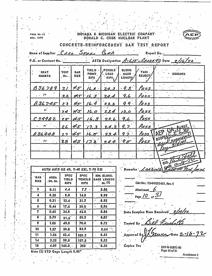
j 4.
*1
* i
I.
* 1
; I
I.
I.
' 1.1
r0RU ac*, ' INDIAt4A & MICHIGAN ELECTRIC CREV. 2/70 DONALD C. COOK NUCLEAR P
CONCRETE.REINFORCEMENT BAR i
Name of Supplicr C!.eo -- ,c'
OM PAN YPLANT
'EST REPORT
Repoit No..
:
., CA4 te,,
,4~ M In
.. .. .
-
P.O. or Contract No._ _ _ ASTM Designation ,,0 D a te _;E1& Date
HEAT TST BAR YIELD /ENSILE ELONG -REAS.POINT LOAD . ,GAGE REE
KCIPS KIPS LENG
s A4L. . .
*Z~~~~~~~Z- ?# 5 L L I ,49.5A~~ S_ _ _ _ _ _ _
C8490a Z54 ZJI0 .A45Sz 36 *#9- i. S. 4.3
. ,**2 ^9/. /.4 Awss I.n. .U. . _
ASTM A615 GR 40, Y.40 KSI, T-70 KSI
. AREA SPEC SPEC MIN. ELONG.BAR YIELD TENSILE GAGE LENGTH
SIZE SQ. IN.. KIPS IN.(1
3 0.11 4.4 7.7 8.86
4 0.20 . 8.0 14.0 8.95
5 0.31 12.4 21.7 .8.95
6 0.44 17.6 30.8 8.957 0.60 24.0 42.0. 8.86
8 0.79 31.6' 55.3 8.80
9 1.00 40.0 70.0 8.72
10 1.27 50.8 86B.9 8.64
11 1.56 62.4 109.2 8.55
14 2.25 90.0 157.5 8.5518 4.00, 160.0. 280 . 8.55
Note (1) STD.Gage Length 8.00"
Remarks ,Z-04b
Calc No.: ED-040303-O01, Rev. 0
Attachment
Page JO of
Date Samples Were Received
Tested By
Approved 8 ate /
Copies To: DIT-B-0285.00-Page 10 of31
Attachment 2

.; . . t . -. -
I... .
F r Cu C-12 , INDIANA & MICHIGAN ELECTRIC I' :.-E *Wv.- 2J10 . DONALD C. COOK NUCLEAR F
*. . CONCRETE-REINFORCEMENT BAR 1
NHane of Supplier C.•eo -7-e' (oUA
P.O. or Contract No. _ ASTM Desitnation 4L±S
COMPANY..'LANT
TE.ST REPORT
ReportNo. ____
-14D D a te e
. I* ETYIELD . TENSILE` ELONG.'
HER TEST BAR . POINT LOAD/ GA RE PASS REUARKSN4UMBER H)o. :,SIZE ws. KP LE TV REJECy
Vs l . .51/,
b~rdr 3 7 3.o &3( G 3L f
*, _ 7 3 S.3 93. .s-37o9#ts S/. f3 5 s.
7 ' 7. 3 - v _
.z zz.7 3A. 6 ;4G Sr_ __
. . f3/ota L9>1 6 z~ 36. 4.9 A/'s5 _____. ,, . zo :fg7 zz, -2 of3 ~s..63 1 o . .. 0
ASTM A615 GR 40, Y-40 KSI, T-70 KSI
BAR -AREA SPEC SPEC MIN. ELONG.SIZE . SQ. IN. YIELD TENSILE GAGE LENGTH
KIPS KIPS IN. (1)
3 .0...11' 4.4 .7.7 .8.86
4 0.20 * 8.0 14.0 8:95
5 0.31 12.4 21.7 8.95
6 0.44 17.6. 30.8 8.950.60 24.0 42.0 8.86-.
8 0.79 31.6 *55.3 8.80
9 1.00 40.0 70.0 8.72
.10 1.27 50.8- 88.9 8.64
11 1.56 62.4 .109.2 8.55
14 * 2.25 90.0 157.5 8.55.18 4.00 160.0 :280 8.55
R em a rls ia G M z/ X
.r
Calc No.: SD-040303-001, Rev. 0
Attachment /
Page -/-of
Dalc Sanples Were Received
Tested By ___
Approved B-/Dye
DIT-B02'851-00Copies To: ; Pagellof31
Attachment 2Note (1) STD Goge Length 8.00'

MOMU ac-izREV. 1/7o
-. . . . .
INDIANA & IMICHIGAN ELECTRIC COMPANYDONALD C. COOK NUCLEAR PLANT :
*CONCRETE-REINFORCEMENT. BAR TEST.. REPORT
Hlir .oe 6 r5, *A .* * Report No.
. 0 #CN ge:2,
;. Ak Fr-oow,,* 61,,,6
Name of Supp_ . _
. . P.O.ocr Contract No. _ ASTM Dn *e Date e-11617z.-
--7--
HEAT TEST BAR YIL ESL EQG PASSVHg-y -POINT- LOAD iOGAGE R REMARKS
"NUMBER SZ'RJ kips . . EPS.- ' HT .* -.,.
. 636 /4', J...$'/0 4 ./0 ss .•i~ ... ____________. .
.U , . 7 -E 6 7_ _ _ _ _ _ _ _s ..41 3S_8 / .s 6 O.. . .... 9.4 R4 /, :v
63. sA57 _: P.
.7 /3.6 6 P27-H8 oz4 3.1 4 w, s'_... . ,. ..- 8 4"O . 64. 7 A As;
_ _ _ _ _ _ _ o 0 9 <J 4 L * _ _ _ 3 -_ _ _ _ _ _ _ _ _ __S
.~~~~~~ .,,Z. *:3fiG3 .
:-ASTM A615 GR 40, Y.40 KSI!, T-70 KSI
SPEC SPEC JMIN. ELONG.BAR AREA YIELD TENSILE GAGE LENGTH
- SIZE SQ. IN. KIPS IH (l)
3- 0.11 4.4 .7.7 .8.86
4 0.20 8.0 14.0 8.95
5 0.31 12.4 -. .21.7 . 8.95
6 0.44 17.6* 30.8 -8.957 . 0.60 * 24.0 42.0 . 8.86
: 8* . 0.79 -31.6 55.3 8.80
-1.00 40.0 70.0 *-- 8.72
-lb. .1.27 50.8 -88.9 *-- 8.64
11 1.56 62.4 109.2 8.55
14 2.25 90.0 157.5 . 8.55.18 4.00 160.0 280- 8;5S
; Remarks 1d/4/-6 l -w /, /
Calc No.: SD-040303-001, Rev. 0
Attachment 6=~Page /2of3/ -
. Date Samples Were Recelved Z/1/7it
Tested By 1 'L''73
Approved B y n eZ
. ... .
;., . ^: . * .
i. ... ... .
.Copies To:
-Note (1) STD Gage Length 8.00D I . DIT-B.02851-00. Page 12 of 31
Attachment 2

Form 1.14J . ;LEMONT [AVIAUFACTUF"UNG CORPORATION
1. .
�� e� IReport of CIMAICAL nd P11HYSICAL Teits of .tLECTRIC
'Chargod to*CECO CORP.., I.EMONT, I ISlp1to_
OrJct No. I .lil .. Ileer * Slob .OiJor No. * No. No. C.
LEMONT, ILLI
FIJflUACE STEEL .#
Nols .- . .. . .
.I , ... :. FILE NO.;
.5 REBAR . .JAN 14
.LL.Shipping Hlatfee . .. '.. . ... , .unihor ATSF 168336 ._ ._.'Car Mlunihxor . _-* -
- - . T - .T -q
ANALYSIS %. . . .
TostPleee.Cut From.
Yield PnIntbs. per sq. In
Tensile* Strongth
lbs. per.sq. In;'
EI g.n_5
% 7
Red. ofArea, S-I
. Tend' .TestMn n. P T S Si.
=_ 9.3D.- 7_6 _ 140.. __ __.9677__ L22_ r OK_0 C34982 34 63 019_ _ . 57741 79354 -21 ____
'Al8 70 020 4 __. - .. _.__'... :.' . __
4 ___1 ___ 6 -78709 *.21
.
I.
0)Oq�.
5.- w-.
-'5 �t�) LA.-..
0
0
.- -I -:-.-
t1 -:. ._
CD
o
. 0
0
.'ka
1 %'t 9
.41 . .
. CONTEINT Q6"Lr IipI
-- 1 -- rI--I--- I - 4 4 - l-
. . . --QUAL T ) THE:ORIP INAL_
I. I - . - -- J.- -- I-- - I--
- . _- . __ a - .... I-
I I.. ..-/ .,? J,
fP-~. - .-
_ .. _._ _ __. __
.: . :,. *) j;
-~ .. . .
"to --:r;nfj7 c,:rtl'y thaot Wtn cboi* rcct oz_ wac~lln<S In 11;- rzr~ord

* rL 14 VA: *; 'LEn9¢NIJ h.U" C"UPMG CORPORTIoN [ON
. : .CONTENT QUALITY IS . . .: .., L.EQUAL TO.THE ORIGINAL . . ... FILE H.________________ '
- :rt .of C:;; I''! , aslC~i.Tosts ELECTRIC FITMrACF STESI 1,-REBAR. . .. . . . . -�- � 19. - '-"' � ..
. Charod Io, -. ECO .CORP., LEMONT, ILL.
- ShIppIng loeo -
A ArsF 168551_ oqr ZiU!IIDOr .
.:- I.. - � -
F F r r
Ordar ho.... , -
.Mill ..Order No.
Not. .* Noot:. o..
SlabNo.
. *- ANALYSIS % . ; Tost Piece. Cut From
Ylel. Polntlbs. per sq. in
TensileSlrengthlbs. perB.. 'In;'
MErW .. % .
Red. ofArea.-c. I Mkn . P Sit
DendTest
=2ni438 Ž7 _ ---- - .2a 2 _ '
_ .2. n3678s . 34 68 m oQ ..._ 5.645L.. 045 - *- _ 7 _ _ _ 34 Z& m 6 Q.L ____ . m4. 1-
.
.1 �'c�*1 *-
:117
- 1.2-.- I.-
I . .
'o 0 X
1R tn-6
t , .
oe
.- 50~
- - - -- 4 - .-t 1 -. . I -IF I
. -- . .. .1.,. . I . .
. .., r* *. . .
_______________________ _________________________ _________________________ I ____________________________
_____ * *1 *. **.*.. .. - ______
____�Yj��i�Ž .*. ____
:
1-1-1 1---j
_- -I _. I _ __.
-. _ _-.
. I._
__ . _
-1 .. I - *. 1 *
���1����**
*k : • i I § ~ o - .* ). 7* . : : - s
- * . * .- . -
:J :n .i.ft' *-,- -.h7

. . . . I- .11
.tL4* 2* .f s
. . CoNTE TQUALIT Y.AL L U"A:4ONT, II.LIN* EQUALTOTEOiiAL
. prt ~rof !!:!.',3CA. ',1 MinilPI;*eCALiTo>sf ELEZCTRIIC FURIIACE STPEL_
.Cherg;l to .
CECO conP., LElONT IL. *
.. A ..It .
... -.. . . . I
OIS
?t6 REBAR11 -
./. >2
J* 1f- '"' ' - .* FILE NlO.-
. JA4 1 1% . '12 .__ - -.1 - 17. .1
.impping l;OxICa -' * JATSF 168535 .
Ccr . - .L.
.I
_ , ., . . ANALYSIS % El_ R bd. Yiolf ...... Tengi_. Re. .Wrer No. drderNHet&Sob Test.laceY.* -. of` Strngth EIn Aea .._ -_ __ . _- _ S_-nt
I r No: No. M . - * Ctjrn.bs. per sq, n. lb. per. n. .:ArtL C |8i SAAL5; *- T. WW 8
/ 0__29 82100 ____ __ ._36_68_ 05_ _ j -_.in. : 20. _ TK. B3676 ' * 36 67 020 043 .._ * 56818 84545 17 I OK.
vi8 - 32 70 022 165o 53636 180681 21I_________- A _I?1TI* i-6 1 -
.2 . c3 16 3 j~ j4 p06 -- . ..- 2* - .1 -J W ---."O;UC.
. I . .
1� - - - - - - rI.. 12.2. I2 2 2 2 2 I
_______ 2*� - - .
___ 22 I I ______ ____ ___iL[ * <.P7Ks;i_1 VTi�___ '
.1 .
.0.
K.: .
*01g1I i 1.
I .-U 0
co
i o0 . 6
1 !a
CD
-I __
___ I ___ * *2*
I'
. . I.i- I-- - -- . .I --------
_ _ F . .1_ _ _ i*II
.. --- _ __..... aI
._ . _ 7. .
.I.- I -- t---J---J- � -J_.__.L.
... .
,- -I . 9 -- r* lei 1:. 'A2-1..-3 a.- 2 2- * o z Id .?u.N r.n:8l:tAj :.4::..c.:: e- .:.~-- 2 *2~ . ,- * ~' ',
. : * * . 5 . . ,. .. ..* . . * , . .
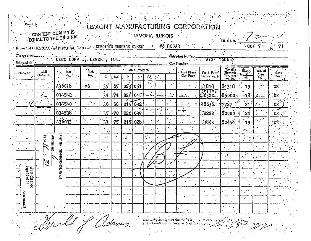
t .. . . . . . . , '-'I. ... , .... 1. . '.. - . : . . I - . c . II'I I . .
. . .. I. . I . . . . . . I I . - . I .. . . .. . . . .. . , . I . . . .
f .r�.
I.,:. ! .14 . * '
CONTENT QUALITY * -ElMON, ILLI*!.-EQUALTO THE OR.IGINAL. . LEOTILI
iso,-ort of *;GM;CAL cld P0IYZICAL Tats of ELECTRIlC FURIITFE C. SFEL' A6
Clioread t* .*:
'G COR.PinATIN.7_ I.
. FIL6 NO. ._ __ ,:OCT 5 . i*
I.
* -II
. - Stirpping ?iaco * -.Saint f;I. -: '. CECO CORP .,. LEAONT%. ILL. .
. .
I ..I ft.- ft.te-s
ATSF 1 68MT. ,A.., s.sTe il.. R,, , ,f
Mi* O er No. ON. .. ..... ... Test PSeco pr*q I re-c M - P S - i - . lF or bsqrq in . In.. % t o : . r s
I IA 38 35 1 65 023 051 .51818 84318 . 19 I.:- Okt(' ' .I I
. I I . I , - - v - I - - I - I I 1 e.c 1 ) 4- 1 I - I ,
*1..' I C34542 34 1:7 62v 1 045' -1-: . - .. "'563a . ~85000,1. .'1 1 8! , :0K,I . .1 _ . . _ . 1 j, _- I I .. --- , .4 . f . ,.
C34540 3 60 1 6 03IO 2 48636 17i27 -I'. 211 . O . .i-1--. -_ . - I ., ,_ I- t . . . . -, . I I
II I.
C34538 . 35 .7O 020 03 9 .. . . I' .52222.* 8booo *22, . . .
. .
. - * - I . ..
._ 18_0633 1 0§ o 8 F- -I. . . . - 58 45 19. . . . .. . . . . . .. .. . .
IJt . .
:
_1 _I. L I
co
t, Is
-U > .)
- CD fl
a n_ et
I ...
_.1
Ca5~
','.' ' ... _
_ ~ i T7T7TI ~~ u0:
_ . .
..-, .:
., .
* :.
:#
:
1:
_-_--- t-- t.-t-�-t-I. -I I-
I..-. . I v
I..._ ._ .....- - -I -I- & 1 _ .1- ..
- - 1- J.- .1 1. - - *
I
.. 1 1:. _ .II; (Abf#vl~ I'I-s - -
:.
.. J., .
*-A. l w r
,:- I atI . n eir.. Is :!.o i i.o - '.. ' . ' . .. ., I. . .-. . . - - .
.. ",) -* _ I
'.. I..-e, -
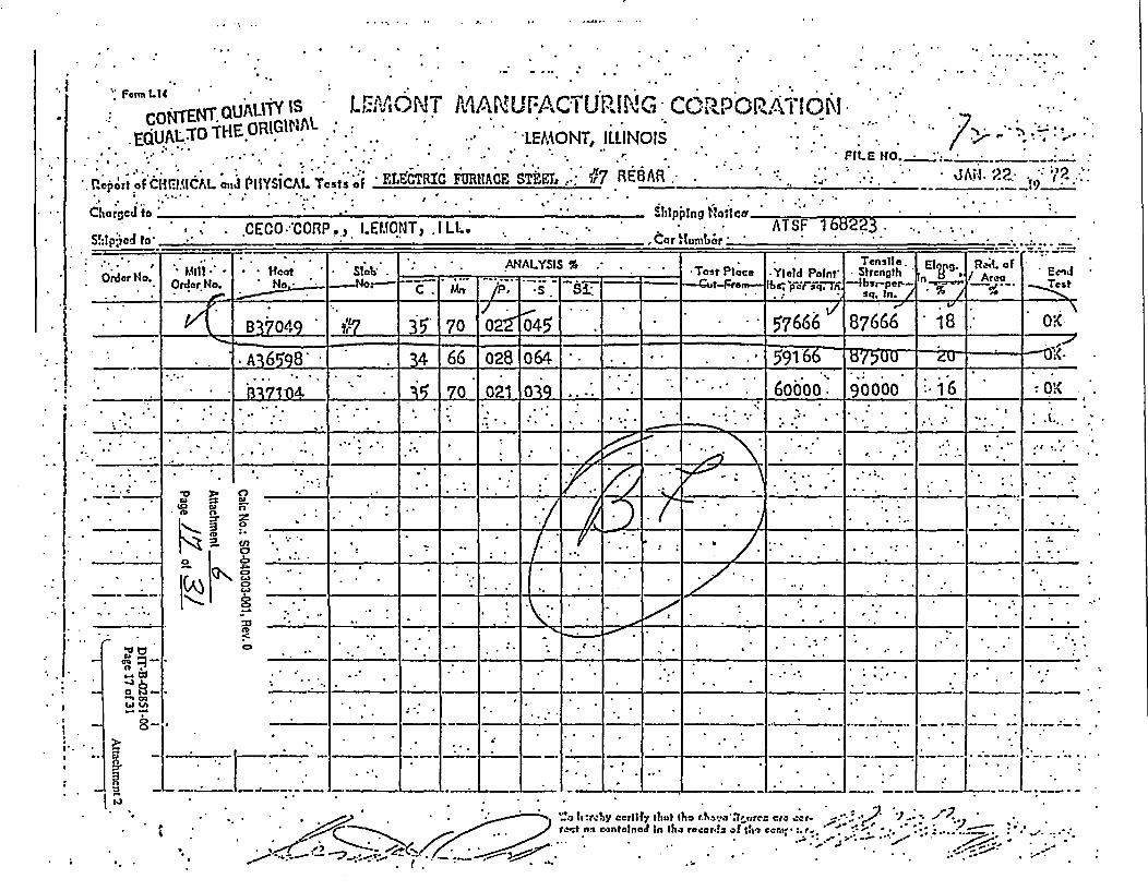
Ftm L14
|of4TT C UALIl L MM Nr TMAlACUFACTURlI G CCO.RPOR. ION .EQULTOThEORIGIMAL
ECoN.TENTHE QU'~" S :. :LEMONr, ILLINOIS .. :.
LEGR FRAEsTkET, .: 7 ROBAR.___________2____VP__cpFrt OECLIIWJCAL ; nJ PHYSICAL Tests of EL.CTRIC N ACEB .. ; . ... JAd 22. 2
Chorciio . .llpjlng flaftcr.rIr~n - .p I C IMT I. 1 . .I * ATSf 1 v8223 .
ItaI"/ e.. , . .%J"Vf - %jwi II !P.Y. gLw%�!v . 7 .. I-- Cn t-_ so -
_ ' - ..-. ST --.
e. ." 'Io
. O-alo
. MillOrder No.
. H . ..No,-
NSlob.ANALYSIS % .-
__ .. ... _ . _ . .
Tost Ploce-Qt-Fra
*~ ~~~ . _es~.11f~ R. _: _ ._iYield Potnt- STensile Eln . f/Area *Ecn
q, In.c. FMtr F17 5,
2__57 66709 7 2. __ _ _6-. 87666 18 0__O
. A6598 34 66 028 064 . . . . 591 __ .-_
.. .331L I04 . . 1 021 109_ -...... 16oboo. 190000 -6 -
A.
, . . _ _
. *' . :55T _ I. . . . _ . . . - .
-
. ID D
0 6-3 .19 eno I
o
C2
c=
/-. -- _t _- % _1 .. ..
_ _
__ T7__ __
. .I
.I
. - 1 . I-
J. - # I _- _ I I *__
_ _ __-. 1 .__-_ .
7. _. . - ,. . .... .
._ _ : ..... >
a
ti.x. I -. .
. I-.. , _ _ _I.--I_ ,I_ - I .
I
?,itr.~ , ' _, 't2atned in 11;...r 2 *! of s,,
* , < / : / .. . r.t t n. con te in eo t In Ike ra. e er~l o f 1 ie e e n~ p . t . . ; . . y ~ .....
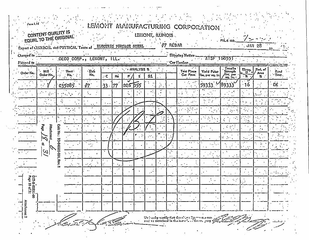
I
. . . ,, -, - .g,1~
4I. n ." Vsrt I AA AN . _! - A 't- I I ...ft. * . -
CONTENT -QUAU1Y ISEQCUOSH~eR~lt4A .. .LEtIWOW, ILLIN!* EQUAL TO h ~~N~
ftcport of CIsPICAL tinld-PWSICAIL Tests of ELEUMRIt6 FURtIME STEEL $
Chorscd to*''.--;
:1O!S... .
7 REBARPli .. . .2
* *. -0fJ 28 * * * :-).1__ __
Shbpptng'Notico* hibI
.CECO CORP. 1 LEM.ONT2 IL* -'-.* <t . . . I
. .. II b r u .- .......... I . . .-
AHALYSI S %** Tensile
Yield P�lnt E �SIrcn�th * i3j**�d
- .*. ,-.. --*1 .1
Order No.- . MOill -
Or!dor No.1,
* * 'Heat:* o. - -
N*Slo.No.
| * *. * -: -ANALYSIS %Tnst Piece* Cut From:
Yiebd P .Intjbi. per sq. In
. Trensile -SlrengthIbs. per-
/ S*. In. -
E5;.-n . 0
* %.:C 1.M Pl 5 I SiArea
%.I
* Osnd *-`T--est..
__1_ ... :5933vY9336k~t t I : j -j.I 3. J~3 -I__ _ _ 3508 5. p7.' 13 97313AijE* .,.
.
;. 6 . : , .. ... ,. .-. *.*j . . I .
.
______
__I__I>Iji+: :1__I__I_____IZKK� ______
___
.I,
.
: II.jl;�� 1 -,14 *:117 i\ .I
L I � I �-4-�--J4.---4�--4.-�--4. 4. 4.. . -. . .
.., . . . .- Li.. , . .- 1
VA * .-U :> 0
0
:r =K °
C'U
:(c)
17A ZLZPd:L.Y.K,j
I. *��**,*� . � *:. **.�.. -�
.
W JA
3 .. _ _____ ____
* 'j " *j _, ',;TiXS j
- I - + +E 1 I1 - 4 I - - -
=--V *E -J.J. _L_.Ii=._ 1 1 - -- I *, ..
. .1.-- _-a__ ___
fi _ _ -. ,v C J

,v , 2.1.,4 ~o~E?'T UAL1M IS .i2Q TEQYAL~TOT'
Fl*.:,rt of ClUmMCAL. e4nd P*llYSi:AL-.Tcst3 of * ELECTRIC.
Charged to -
i;pp .l t* -. CECO *OORP.,_ LEL ONT, I I
. .U2 .fu-1.16V. l\C$5- i. %. t13
L...LrMONr, ILLINOIS.C S.LI .E .
Runi IMCE. STEEI, u8REA
. . .. T IL .
t, . t .N. .. .
~i 71*. .. JUN IVI) - - .
--- -----:. *-. * *' Shipping 11.0oco -
*- ACar crATSFLL. 6a 68149 .
Order No. * MillOrder No.'.
':."ot: No.:
- ANALYSIS %. Slob
No.Test PleceCut From
Ylald PointIbs per .qjn.
Strength IVl **.
fn: per 1'A% "Rp J7Ard'
! of.0 Test
,C_.Ib - PA-- I-S-:O. 357_0.K
. B35501 :86 35 73 02. 04 _ _ 0 4 18 _
0 . C33682 . . .33 69 01.E 03 . 48481 80126 . 20 . £oK,
A349P.. .: 35 .6 01 04 .... 48987. 8063t 19 = :oK._ _ .67 - .4 , .-
._ ._._*: _. A34988 ._i 36. . .6760 03 ..:. 936.- .76202 .21 _2 i..
- C33685 . . 35'. 6'. : 02 _ . .. .. . ..*. - 20 -______ ____ _______ _____ _____ 4~82 79?4 I2
I I *I--4-4-I-4.- I-4-I I
,; , .
7 -_- I
Ia -
.. ,- .. :
__ _.5
I o
i..C 0
,�4 �-- �, I . . .I ....._ _ _ , . . . . . L - -
I
.. :�el�Iv(J-�JI*A�IZ ___ ___ __
* . . . . 1± 2 Jkil) ______ ______ ______
_ 77fl� ___
7I--...
_ _ _I -- r -I-----' .; -..
.-:K.- 14 .. I- -___1_.. _ ..
w.__ .-. . I. -I-
, ~ . . , ,, t........... : . !V t t-. ' Ii.. ;*,iC C i~ .'t nI .# r - - '
.~~~~.. .* . * . ' .

O . .O N. .. .' ViTENT Q11T
* EQUALT0 THE ORIGtIAL , . itt IE ONT, ILLINOIS .
. . ' oTN~Al . .......... LE*OT *A *: CTRG :C*RP*'O. : .* .FLE O _**._ '_
S . . ..O . . ..______oc_____IE TR C M__ S RE -1
B JAt-1. 27 ** Charged to ._*_:_*_*_*_*_Shipping _ _ _ _ _ _ _ _;
CECO CORP., LEVIONT, .lLL. . . 'U * ' AT.F 16825_
Rd_ . _ __ _o
.__ bn*;ANALYSIS % r . 1 1 _ Tes_.ordai No. No N.. nAii- .C~Frm Im ~ . lbs pe
mme: 50 _ * ... .. . sq -t'-.'.T__st_
Sl sq. In._
I 15 t--~ .; Ji '-- "4 Ubb _. ;5S4 I tS6Z 1 7 - 1' OK'
.I-r-, . . . '. 79 n24 A 4Q .. I
1 1 A A__7?n .k - r, 11.
,_ ___ _._, -r __ _ _ _ F.tZ _ _0WI '"1
I. J---J 1...i - - - - - - __________~ - - -..- _I_____
__________ _____________________
________.1
I :.,
. .. . . .. . ...":, I --... I -
- -*: * . ¢:w - - I -t - -4-3. 4 -,'- F -� 2 -i I� -- A-I - 4 - I ......... � I
- 1- I °
-I F I _
,/I7 -/ W " ' :.I ' 1: I
* J \-1 . . . I -. . I *. . *.
. . . -
-
* . _
* t9a
O~~~tgo-~~~ . :. __-.:''..I
. .. ..
*i ____ ._ _ _ _ __-s_ _ '_
I _ _
1Ca* ~' 7. - .
.s
S. . .' -

. F.. r L ENTONT .A UnA 4U yC MrP.I)Jr' COG PGRZPORA ON:p~to~tI-I .. '-.1 T .:. .. . LEMONT, fLLINOIS *. I .
. ; .L . .L T. . .S - FILE NO.
RCepaori of cHIMIAICI- nd P!YSIC&L. Tcsts of ELCTRIC UICE'STEHtU REBA .
* . -CECO. CORP., LEtlOi;T, I L. .1b311Cm.> .totn*. 11 #. ) . .tA
:. / _,, I.- I-)*/._
- JA4 2519.
72
I -
Order No. Mill H° t Slab C___ ANLSS . __._ Test Plece Yield Pott ensiegth Elun. Red. of, , _ _ .olot _lrengAhOre o o 4* C l * P S SiCut From lbs. per sq. In, lbs. per Test.~ Ae
* . . ~sq. In.Ts
24 _ __ __ - - _ 6 .. . .' _9c
_ 4 351.57 . . 36 4 57463 5316 |i ./
-3636688 6 : 026 o60 . . ___ _;_.53797. *85569. *1~' -, -__ _9..: .. 4, ..
- . . . ..- -. .':.- ___ _. **. ........ ._-
- __ -_ .. . _ _'
I.~ . __ .-.-.-I. . . . , H-
I,:" -..
I
* . S. .~ .
-D- C.)
- .*hI&I
. .
1- . -
5-----
.1 ..I ... ,,. I. 2-7
.:*. . S. _
-4--
___ ___ I ____ ___ I ...
-- a- *I._________
__ _ I_I- ___ I. __ ___
.
._ _ _
.. . . -.. .- 1--
___ , . ..L -,................_
I,* ..-- . * , ', , , * * *I-.J. * ,* r . *

. . .. . .. * .....
Form L1UFl ' *. !EJMONl T AA M AU A CTUR ING CORPO AI EN0
Co0TtET QUAJT IS..-~~~~~LEMONT;.ILflINOls*_ __ _ _ __ _ _
Rcap 0i-of CHI C.tIC arid PIIYSfiCL Toss of eA.CcTM, F "' STEJL i~l 0 REBAR . . . a..... 30 7
Chcrgsd to" **hpping Hotice '
i! * CECO CORPC.; drjt¶I'I .Ll. :; _ *. . *. ;b AT&,tu.e168333. 163.. ~~~~~ ~ ~ ~ ~ .. ...__ .______ ,____ __________ 3,_,____ ___-
=
. oret No,.. . . _ ..
Ordor No.' - Heaot.*;NJ_.:
Stab.
... ANALYSIS %,Test PieceCut From**
'Yield Pointrbs. ,per.sqtn.7. .
' Ten'sileI Strength'..I bs.:peret_
so. In.
Red. ofArea
,-_
tdend '.Test.-C . Mn. , . ..S_ i -LK. .
'P.:_.|. 1 1 1.- I_
_B6144 41io 37. 78 019. 033 _0 . 7087 8 2Og___=-3- __ _ ... . . . - - . ___ __.._,_
__ . . 3426 :37 73 015. 030 . : 5_0787 . 81889 20 OK
. I A35615. ._._- 36 72 020 044 . _ _. 51968 36614 . 18 OK.-
:(__3. ... 36131_- .. ~=37*- 70.- 020 0._ . .. 5157AL13A614 8 4
: B31 °5 : :. 7 - 47637. 81102 19~~.. ..._.. _ 4. .........*' .... -L
. .
.:
':'.'*
...
. .
:::
,.. Ia > r
(0
C-)
Co
(c
C
* I*. F . I I- -1 T1 - -- -- ____ _ __
I I __
.:
;/. Iy '- f _.--I- ----- I ' &- I I. ,
_--- - __ .
31<_1�YI 12.- /'
-i --m~ .....t... .---- Of-''-.- -'-'-1---'
r..-.t U5 cantchled In i' n aeor If: . .. J_.o'....'_a, ./) ,,
4 -a--',
. .

I
FORM QC-12
kEV. 1/70
INDIANA & MICHIGAN. ELECTRiCDONALD C. COOK NUCLEAR
CONCRETE-REINFORCEMENT BAR
7*..COMPANYPLANT
TEST REPORT
. ., e
* * '(A' IE Fz)
Name af Supplier t t,
P.O. or Contract No. _
S1 7''--
.
_ *_ '___________ Report No.
Dc . .iaect .iDesignytlon =, IDate 7 2ASTM
.4* I -
* I
I -
.1-
*1*
* I
I-
I...
HEAT . TEST BAR P ' LPT TEN EREMARKSNUMBER No. SIZE K REJECT REMARKSKIPS KIPS LENGTH
___ __ / 7 // AL.* d 2S i _ . A S * _ _ _ _ _ __ _ _ 'z L . 4s A/S S
. ^ ~~~~~e- . */7 8i- 27 .0<A.s/3 3 7/.7 /2 _ _ 7_ _ O_ . .
* 6/ q/ ~,'/ B/a0. /Z ' J.9 2C. R-
/376 7 9/$/ 7M / 7S9 .
,./0 .. 830,' I? PAS ' .e B-. / ' s s3.
ASTM A615 GR 40, Y-40 KSI, T-70 KSI..
SPEC . SPEC . MIA. ELONG.. EAR AREA YIELD TENSILE GAGE LENGTH
KIE .S .I . IiPS -KIPS IN. C)
3. 0.11 4.4 7J, 8.86
4 0.20 8.0 14.0 8.95
5 0.31 N 12.4 21.7 8.9S
6 0.44 17.6 30.B 8.9S7 0.60 .24.0 42.0 8.86
8 0.79 31.6 *55.3 . 8.80
9 1.00 40.0 70.0 8.72
.10 1.27 S0.8 88.9 8.64
.11 1.56 62.4 109.2 8.55
.14 . 2.25 90.0 157.5 . 8.55
18a 4.00 160.0 280 . 8.55
Note (1) STD. Gage Length 8.00'
Remarks IQAbA46 Z4T 1-7 $4z, Z/c't
Date Samples Were Rece;ied
Tested By ;
Approved By. D e
Copies ToCalc No.: SD-040303-001, Rev. 0
* * Attachment
Page 2E of

*O cNTENLQUQrfljLEMONT MANUFACTURM3G CORPORATION.EQA--' HE ORIGINALKt LEMONT .ILLINOIS...'
*FILE .. 7, i
,i 72Report of CI1El.AIC1.L ond PHYSICAL Tests of ELECTRIC FURNACE STEEL
Charged to
S!Jtnned io CECO CORP., LEIMONTy ILL;
1. REBAR MAY 31--- J� �
_ Shipping Notice
e.. Hann4
.. ,ATSF 168480
'AALSI %TensileOrerN. Mill . Hat:- slob *..*NLSS ~ ___ Test Piece Yield Point Itregg Red. of BondOrder 14o. OrdSr No. _ c - t . * S si Cut From lbs. per sq. In lbs. pIr Te rea Tast
_ _ _ _ _ _ _ _ _ _ _ _ _ _sq. In.
::|_6___ __37 73|__ _4 | ,,20 |85897. Y 318 Of "I* 34 73 32 O5
A A73 .yG3 044 . 51923 . 82051 '2;c
. _____ 37 70 021 047 _-32P 82692 22 __Ot
. -.. . . . . s. . A- '
.H1 *4 i 4.Si.'s ,
-44
S . . . .4
. 4
S
wD = E
w 3
0
o i CD
1X1 °d
c~
6
I_. I I I7 i m .. I. I 1 =1 .___
. K:
.. L-
- -. ___ *.. __
- - - � -
.5. C - - - . . .5
____�i����1�.. ______ ___i_I
I. . .
.. . . . .
We horeay certirf that the above fioures are -_. rect as con!ained In the records bf the campn
* *. . *;10~1 - - *-,-.

for L14 '
feormLW4 LEMONT MAN'5UFACTURING CORPORATION6O3qTg.E~QUA0Ty is
' EQUALTOTHE ORIGINAL * LEMONT, ILLINOIS
0.I-usitr1t JtrvlseAt * .X.t ELECTRIC 'URNACE STEEL 11 REBAR
F E . . .
FILENO, 7 1 ..- /-
I. ,
I
*AAY 31 .- I 72-* xpOrraO ..t5Lfla' . cnQ II 41X1. I U~1u ndT - -t 1 1 t - -
C rg to . . . . .:Shlei to . .- CECO C.ORPW.*, LEMONT. I LL. -*SlhIppid to__ _ _ _ _ _ - _ _ _ _-
_ _ . I. , -
ShTpp1nq Noiice _
Car Number
I . .. .-
ATSF 168675 .
, Orderfllo. .:MillOrder No.
Heot.. No.
* SlobNo. -
ANALYSIS % . Test PieceCut From.-
. TensileYield Point Strength
lbs. per "q. In - lbs. perI q. in.
n:Red. of
AreaC Mn P S' Si
Bend. Test . ..
-01
F F 4- 1.-�1�?-1r1tt I 4 1-1 -t
ltoisc . A36838 .- JA1i . ;37 70 1 42 047 50320 1 82692 22i .I I - 4 +-44.-4-419*-t
LOIC A 37 70 02 048 5o641-" 84615 * A17 .I' o:(
vvi 8377o6 . 37 0 _0_ - 53525 &883O1 17: t7. 0 53'.
; .. 35 73 01 6 037 _ _ 84. 1 8 / .. O:i
- -- A37636 *. * *37 73 022 045 * . _50320. 85897 18 -.
a. :.
, .
,':. .
. -
trt = wx
* CD C
I7aŽ'U
I:
______ ______ A ____ ______
__ - .- �- --
I
- �-4--- -
____ t _____ ___ _____
* _________ - - - - -4.----- . . I
____________ * . . 1*__ __ I __ __ __ _
. , 3 Wo hareLy certify that theg z * -t* , rect ct5 contalned In the I
. . I'
) above ficurns a;r co 7-
,acords of the compony: -
. ......... - . _ _ ,_ _,
*6�< *w-

... .1 - -
.W * ENT QUALIT LSEQUAL TO THE ORIGItr4
.EMIONT MA1UEFACTUrG1M, CO. LEJAONT, ILUW'OIS
,PO nLATION -. -
,~ hk
. ./.- . _
FILE : B , 3_n__ '.- 2tIJAR 13 ,o. 72
Report qf CHEWCAL'aind PHYSICAL Testsof EECTRC RCE STEL
OCarned to . . ' -
- 7��
. ,-1 .'t \ CECO CORP.. LEMAONT, I LL.. ceit.t ATSF 168649-
N O Heat Slob - ALYSIS% ;_X_ Test Piece Iesd per Tensile /Elpg.. Red. of TestOrefo Mill SlbStPee llStrength Bed.re Order No. ,..N. o Si rwn ls ers.~ lbs. per - Arn Test
__ _ _ A n_ __ __sq. In.*.'..7 i 39 2 -;042 | | 87 89102 21 _ OK
. A36334 ._. 38 .7 01S Q45 55769 8 576 19 OK%
-:A166 :_ .S .. = 2 041 . =2 %884 8249. t 6 = OK..
I -
.'
______ ______J_______ _____ ______T:.1.7ii�;.:�IT"' . . .
. I- -I m' I
0 QJ3 Z)
ID a
1' U
_ . 6h6_ :D
o~
.t
.-
. . . I
_" I'. . I
gtt
a tt
w I
I 9
td
S
0 .
3-i.
e '£ c�nt:1n� in the race T�T2 of �- ______________ j.L....LL.�..LLJ....I.I.-i. .1. -
..rb, \ ri t1cy trht AOh o lota* nuCa are* s . cont-in In tho rocorls ef thoiccnS

w . t
O. FSM CC.12't . R REV. 1/70
*NaHme of Supplier
*; P;O. -or Contract No
INDIANA & MICHIGAN ELECTRIC COMPANYDONALD C. COOK NUCLEAR PLANT
CONtCRETE-R.EINFORCEMENT BAR TEST REPORT
*- : .,e
. . -~
elo_ -60 zj°, . Report.No. _
& Designation ________________ DateASTM- ,,, ,,, f
.,
HEAT TEST BAR YiL ESIE LN PASSHUMBEtR No. SIZE POINT O / GAGE/ EJREMARKS
KIPS *KLPS LEHVHH
/3 3 2. <zz 786 okI.v .S~ws _____
~.±.I/<1ti42Lr/29. 3 4 . 3_________
.7. 9 1.3o.3/ 9.4 A4 ss,
A S4 782- .2 Fi/ 789 3 / 2.X z . .f 8___ ____ __.A 13,
,,: 9B LZ !;v. 4,0 -3-0, z f2_ s.I. :I .~L .0 .2. . 1 ± .~ ._ __._ __.
._ _ _ _ _ ._ __ _ _ __=* =__.__I__.__'._
ASTM A615 GR 40, Y-40 KSI, T-70 KSI
. SPEC SPEC MIN.'ELONG.EAR AREA YIELD TENSILE GAGE LENGTH
SI E S .I . KIPS KCIPS IN. ()
*3 0.11 4.4 7.7 8.86
4 0.20 8.0 14.0 8.95
5 0.31. 12A 21.7 8.95
6 0.44 17.6 30.8 8.95
7 0.60 24.0 42.0 8.86
8 0.79 31.6 55.3 8.80
9 1.00 40.0 70.0 8.72
10 1.27 50.8 88.9 8.64
11 1.56. 62.4 109.2 8.55
14 2.25 90.0 157.5 .8.55
18 4.00 160.0 280 8.55
*:
Date Samples Were Recelved ____/____'_ _ _Z-
Tested By /! r. . By.k,( t *7/* A
Appioyed- By a M./5l Date ?Z
Note (1) STD Gage Length 8.00'
9.
* Copies ToCalc No.: SD-040303-001, Rev. 0
Attachment 6Page 22 of 3 /
.

LERPION-T MANUFACTULRMING CQzPOPjTONCONTENT QUALITY IS
EQUALTO THE ORIGINAL. LEMONT .WNTOS*- * * -* * *e * flR- n Art w*
. .1 . .. .
I
/J. - - e*'U..
FILE I
u0o 13- ., *72Report of CtE'.'ICAL and PHYSICAL Tests oj ELECTRIC FUMOLCE- STEEI.. Tf I I 1LtolIII
-I-
Churged to.
* SIhnn,, *.
*ShpTn.,Q~ Hotuco,
.CECO.CORP., LEMONT, ILL. Cnr Mn>r ATSF 168649. . - - -� -� -. - _____________________________________________ _________________________________________________
r - y I I - r 7Tensile
Order No. MillOrder No.
.. Hoot .*No.
.Slobh* No. .
'ANIALYSIS % * . ., , . f .
Test PieceCut From
Yield PointIbs. per sq. In
Slteng'hlbs. persq. In.
Red. ofAreo. B3en*d.
.TestMn P SI
i1| B37097 11-- 39 72 0 '_4807 890O2 21 OK_04 -79 8' 76 - "
A36334 .. 38 76 oi. .. 5769 85576 9 '
- A36682*. 7 . 021 041 '. 52884 8493 5<i 6_ I.-OK
.
'-' ta.
j: :..j:. �.:*: j__EEl-I-H- L�I__ 'Ii
I.
.. . i-
-u > c0
to i
o
w =. wC.)
(06
701"�.1*I . . '
0E Ct-. * 2
V. V
.t ,
S
I .
_.,.* . . .herety cettfjthct tA* aboveflgu ci** .:a .s contained In the recorde of thecoepn

* * _ .1* * . _ .. _ _ . _ _ _ _ _. _. . ... .,.,..._:._.r . . -. I
FawmLi4 .
LEMONT PAANLWACTiCFRNG CORPORATION.\CONTEMT QUALITY IS
\U.AL TO THE ORIGINAL . LEMONr, ILLINOIS: . .-
Report of CHMA*o anJ PHYSCAL Tests of ELECTRIC F URIAGE STEEL P11 i REDRtR _-. *
Chorgod to . - ;4.t1tgtoca
ILE NO. -APPr 26 .
. _
. \ CECO .COTh:'. , LEI !T,. ILL. - . *- . c 1 J". tj.._tT"`F 1 6V297C A s P.: P -r l
.A A. a . - . I _. nu. ._ . .
* _ _4 .
.Od .
Order No. Mi ..Order No.
: Hoct.*No;
Slob* No.
ANALYSIS %.
. . .
Test PieceCut From-
*Yield Point.1Ibs. per sq. 1
* TensileStrengthlbs per5sq ln.
9 % I
# %7
Ked. ,At-in
Df I ' ,. I
1,e I r.¢. C Mn P S Si
..i~~~~..1..._
* :.;./ q352148 #1/ 39 79 o1i' 039 - 522.3 o7820 15Pi
. C330 . _ I0 7c 02 C .1 .- . 51923 81730 e16l6jl 52t6| | 38 7 79 02 05?c 5h 87 8374 1 1S
..;...A ..... I .. )A 3526 I. "' '\ ~2..2~ -'''1I- -1 - '___ 5lit 8 = t97 ... i - -=
:. . I.I
. I
....
.. .p .. .
. . ..
%O. .
*' s0 "W _A
0-I
I" : > C
O' W
(9 C I
I~x
.- . . . .V . . . . .
� ... r. *� _____
- V 9 . -� *� - A-I
V . .
______ - - * a - - -
* .. .. ,*
CD. . . .
o____ - -�- - -
I .. 9.
_ 7. __ _
I1
. a0
* .4 : .. :...-*Sy certl* tht tbo eaovo flOuros en cot
irecords of tho coaIs y

Foe- L14COT- iMONT MANUFACTURING CORPORATION
-fEQ LTOi-iE OR1GINAL \ LEMONT, ILLINOIS.-
.. .
.
:N..
/ 2~.Q/ '. *--
FILE N1O0Z. . C . n YC I
Riport of CHIEVlICAL and PliY~iCAwL TeS'fs of -FTErTIIIC F1INACE STEEL .' §11 REBAR. *.AR 13 ,I cTo2
Charged to *
Shinned fs *. . .CECO- . .. .Shlpptn'g ktlotIee
.... ..
, I-
Pn, uLEMONT,L iTSF 168159. . _ -.....- T
. COrder No. MllOrder No..
HeatNo... '.
Sleb-No. -,
\' ..* ANALYSIS 7;Test PieceCut From
. IYield Polnt
Ibs. per sq. In.
* Tensile*Strengthlbs. persq. In.
Red. afArea
%5C Mn .P S
Dind'Test
B37097- L* #11 39 7-2 0i' 8 1042 .. # 10 - . .I ; -- I-: ' ': 54807 ' 8910o2 21 OK
39 75 022 I03 55448 89421 `15 a OK_ , ,- .: -. __I_ -I __ IC______ - I - _ ._____-_
40 I024 0f; 519i :188461 17- - -- -- , -- --- -- ~ - 4 I
QP 1 1 5224W 81 7i 18
. 0K' -
:. OK -0....~ I
- 4*- - 't- - - - - - 4" t 4" 4" 4 . I .+ 4 1.
I.
-t � t I - t�t 9
*1'.,F - 4-4-.-+-9-4--4"-I 4" I -
I ., - '. ...f-
-. _--<-7. � 7..i j:_F��I�.___. . .
'ir VI.
0 . -a-
a .
- - - - - - - - - r --
a a * I- -� - - - - - - -__ - -I---..
I1
BI-
Woheraeby certify tht t bove figur~es e cer _ t7red as cantained In the res of hecow--
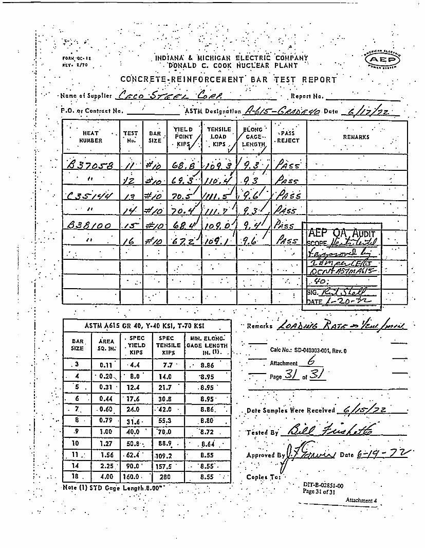
3.
- I.
.3
I...I.
* I
3.I.
) I.A I
.1
.3
*1 e.roa c. ,
rOR .' Q2C-
RrY.- 1/70
*~@ . P . .. , . . .
* . . . . . . .
. INDIANA & MICHIGAN ELECTRIC COMPANY. ONALD C. COOK NUCLEAR PLANT
CONCRETE-REINFORCEMENT BAR TEST REPORT
ler 6 'eo 5 6!o<e/ . Report No.
... ., 5 U
* Name of SuppI
P.O. .or Controlet No. _ ASTM Designfti on 4>/ &d~f)4<. D aIc_
HEAT *R TEST B. ARzYIELD TENSILE LONG .AST REMARKSNUMBER NO: SAE POINT LOAD GAGE- - REJECT R
.p, KIPS . LENGTH .
O. , . -. . , ' ' ' _Ass IT
At
.... .- ............... : ..._ SG t_
. . '.. * .. : * *: . .. __ ATE _0..
ASTM A615 GR 40, Y-40 KSI, T.70 KSI
SPEC SPEC MNI. ELONG.BAR AREABIZE SQ. AR YIELD TENSILE GAGE LENGTH
SIE So N. IPS KIP$ IN. (1).
.3 0.11* 4.4 77 . 8.86
4 0.20 8.0 14.0 '8.95
S 0.31 12.4 21.7 .8.95
6 ' 0.44 17.6 30.8 8.95
7 .0.60 24.0 242.0 8.86'.
8 0.79 3I.6 55.3 8.80
.9 1.00 40.0 '7Q.0 8.72
10 1.27 50.8. 88.9 . .8.64.
11 1.56 .62.4 109.2 8.55
14 2.25 90.0 157.5 * 8.55.
18 . 4.00 160.0. 280 8.55
Remarks
I/
-104-A&A ;A&- 6 X., 8-t 1,//. .
I - Cale No.! WD-ndnin.-onn Pauv
Attachment C67
Page 3J of
Date Samples Were Recelved
. .
. .
.I
.'Tisted
Bi X�1& -;Kremlin
'Terted Bi i
Approved By Date
Copies To:C o DIT-B.028511-0
Page 31 of 31.4ttachment 4
-Nole U1) STD Gage Length.8.00"

PURCHASE ORDER
- D ATE I 0 c. 1 -7
MATERIAL RECEIPT
r �1
RECEIVED AT
Indiana & MAichigan Power Co.Donald C. Cook Nuclear Plant Const. Dept.
P. 0. Box 458Bridgman, Michigan 49106
kW Qe-CooCP.
L
ORDER No. I 1C; -Q
IMATERIAL RECEIPT-To Main Acct'g Office
REC.No.
PREPAID (%) COLLECT I )Bogs Barrels oxes 1BundIsICartons CoilI Crates I Pkoes.I Piecd.
I II It -1 I I I I . ISTORES QUANTITYBIN NO. RECEIVED I T EM S
QUirLAE y i STOREDcs
_ _ . _ __ __
UN O D DB . 3 =O A W ST-OT-ED ___ _ _ _ _ _
H1OW TO BE USED ULSn i + -MISb e Pd
Cvor-,. Bida. ff i s-Oe ~I Pi PART I i FIee-51-Shl-.2eS ,. .II
Data Mate.ial Rec'd
1( - SV - 7Date Fin'md
_ " o - 11 ;- 7C.;>
lCarrier I ) m r I Express I rafe IFreigh I ' Weight I
EIHm No. U s L sFREIGHT U.P.S. 5 V
F.O.,. DeslinationDeduct from Invoice
SMaterial Recoipt No. 1 % ;3 .
Calc No.: SD-040303-001, Rev. 0
Attachment _7_
Page / of 32

FOM47T Ftcv* tA
' C; < r- 5- C 0 M 3 :P U 0D: X .^ .i .z;'.UG'51..OD- FO2 7 tB
Company Chcrgod* * /0 / & /2Step No. CO 61 7 0-Coco Stccl 4-CCoco Eroc-ion
:In* ' .3i .l7 Naoo 5incti.%rr k I;'ch E. i.c M r,-A0d 0 Acdross Em^c #i6 (D.C.. Cool.c P7,a;t)City Statce City Bridtfn-,M Stat Q .______
DESCRIPTION *COSTItNG DATA
NO. CON. P. E T . , c O(STRICt PRGG.UCTKGS. TENTS ARTICLES , JL.;T ORDER NO. CO-c WCIGHT
:2 V. .TO-.
B s '-oi forcing so56. { > . 9 ___ 3 _
job p _o ___ __ _ _ __ __ *. _. 1 . fI I I
-H_______ _______ .. .__., Job jphon^.: 616-!.w55-59OJ - V -
_ __ _ I1 _ ____1!
i \ C. O. D. Rcmark:
(NOT C.O.D. 1t_ ;d:unirs: cS.- ount
- is shown) Ta
: - \ ., -::
Mt.cricl Reccived By
Xf' IIA'I,'W-tf> ;'./0- 3-* Z
.. . .Z: 9-
d: f• dtA e
_ Consinco cccepted sood; wi-'.out e;,to.e
-- a Consignee took exception. Sco olt cr sido.
. ..
i ..
I::
. .i..
i. ..
. .,
Calc No.: SD-040303-001, Rev. 0
Attachment ____
Page C of ,32
.i...

stc;t .lo. uic o .Ž,'&. . .
Comic..y Chocard*
7 O CCco S.ccI = * .Ccoco ErecticnDer i . _
Adcarcss -
lomozfc. 52, a Norme Lsz B _it'1 6 _ C-..._C c.__ _ -_ 7
Address , Et;; la,1 (i)^G. Cc.J¢ t.::r 'I, -. ',
State _ cit~y E--i dm:. -i� � -2�-C-f- - IDESCRIPTION | *COST 4G DATA
NO. CON|Io1STR:CT, PFOIUCTNO. CON. ARTICLES U ,I '*21 ORDER NO. HAGCD coDC wEICbIT .KeS. T TENTS h~!'TTO ______I_______
|w4) | Bks roir.tozc~ing eoL; Ji| | 9~3-87o CE;07 ('5\ | 3 I I.____. f_ . TO
. -_ _ _ _ _ _ _ _ _ _ _ _ _ _ _ _ _ _ _ _ _ 12_ . ,'I_ _ _ _ _ _ _ _ _ _ _ _ _ _ _ . _ I I i
. IlJob phorm3: 616-41654-901 T I I I, C. 0. D.
S._(iVZO C.O.D.unlezs C ;oui
i :1 *.ow jn),. .. . ..... _ .
. \ . ,
: . I - s .
Rcremk GAS. .. I,..atorial Rcecived 5y
'. /,/ //. ~-S 1'e t.
IC' - 5' - -7 ZC-fy -7,
A;'RCI
.-:: 29 9-0T,-.-rzd: ge- e
1.�
/ r-7 Consic.ec accepted C.ood: wi...out e
Z Consigneo took exccption. Scc Ot:Ct fidc*I ._ ..
. F
* S.3 . I. 1 0 A S .3 S5A, A, Coco GC/Oa1 # 6 S277 .I
- -
. .. *\C~ 0hol - e ;§
. \ S1 # j*\ \Shoot -
-~ ~ -ho S ,. .
* \~~V, Shc o' ;
: ,
; ; J
\\of
. . Calc Ni
Attach
Page.
. I
- !
: I
Raloas30 PI_ _ .-
.
;.I
a
.. ..
.~ -.I
D.: SD-040303-001, Rev. 0
ment /
3 of o?

7 7. 7 .- F~ ..
.THt-E C=~CO CORPORATION .- .. 0*1'co
CON-ToACTO J1..
* -rIs~ ~STRAIGHT BARS*COLUM4N x J. COLUMN q*
312C 2 ~~GRADE REIN."-
4- ~. jTAG COLOR_.___A1.71 4. ~ MAXIMUM BNDL'S. TJON
_ iF 0 IMILL TEST REQ'D..-. '
A .- - - ------ * - - FOR THE CONVENIEN'CE OF THE
'ru; - ~CARRIER, HE IS REQUESTED TO
-~ ~~IN 2HOURSA . PRIOR T0 DEUIVERZY TO ARRANGC4
A ;F.OR UNLOADING.
__ .. ;1) IT IS THE RESPONSIBILITY OF THE CONI
~~l ~ T .4 ~ .. , .AGAINST -THE .'A7'A'CHEO~ SIW -. NG'LIST'
... ... 2) NO) CLAIMS FOR SHORTAGES WILL BE.: . :CONSIDERED UINLESS CECO IS-NOT)FlfD
V.; .. WITHIN 48 HOURS AFFTER -AtfrikVi4i~ ~ TTT~V.AND GIVEN 'A -REASQNABLE-.' opfiOR.
4 ~ TUJN1TY TO VERIFY THE ALLEG;D:SHORT
I.//.9Aj#7-?s 4 YJ4'f' 3) NO REPLACEMEHTS WILL BE MAADE VN.ie~ .LESS THE ABOVE PROCEDURE 'IS FOt
J~#~? /o~'~ . ~ ~ ILOWED EXCEPT UPON rRECEIPT -OF AN-A/e Z1:c I A
.I EXTRA ORDER.
.74.
---- 4-..- 2 . ....
. Caic No.: SD-040303 001, Rev. 0
*1 I ______L Attachment
*~ *~.. ... & Page of~~ -

.. , ;* .t. , * -* .t. 'I ' -.-- *'*- '. .
.THE' CECO CORI4OF2ATION -.
''- * t
O >R Se.R W_ . 17.)J .coN r. No. 2'
ISHEET -fA_
4DATE
4 LlStrED B Y -:%
OATCFIAL fORLIr I1 C T ONQ DV/G
U - NSION *-. ;.j OUT. -E N
CLL &XJEI4SJ(:tJS QOtt rQ OUxT . . . .DIMENSi'JNtS OMITTED A~t 'F.a
Lb;*, . __. A
T r
: 4 _r .j_ _. .4-:. _ .[ _ _ 1 _
:' C1-,m -, 71it It '1. 1- 7*'24-r'
,. aejH? ,, , - ;I _
.C. . S
. t- - r----- .----- 1 --
~~~. 1 1. .*i * ,I *| j* t°-1 . I_ - ; 1 o ./
X i-~.I---ri- . -t*
X . . . . , I . j. ..
iiT I I L- --111 11 a . --
- .'C .•F I.iGi. , t' - > U R . ; .. .III_-- 4- + --t_
- �*..- � SC
.i.k:iL..�IL2�+2 -I!� }h)4�
�T �K7j7}.#>sk�ItLITLTIT vj S
- .i
I
t i' I I I
I._ I ,I ^, _,_
- ! 9- ! . ' _ _.-
I.I
.. .; . .
r --- * -j1_---_. * :j..
_ . ._. . I _
i-4
_ _ -4 _ _+
I
- .. - . 1-
I .;.i. -. ..Ct .4
__ a *1 ;. __ -
I [ .
- j
Calc No.: SD-040303-001, Rev. 0
Attachment
Page .. $1.. of 32'
tl .... 0**. *C*
Vf
- i - :1 ' ! .j ;. J. .. !. - I . .....-
-I
!d-
IP,.
c.C
t~..
1) IT. IS THE RESPONSIBILITY OF THE CONSITHIS MATERMAL AGAINST THE ATTACHED
2) NO CLAIMS FOR SHORTAGES WILL BE CONCECO IS NOTIFIED WITHIN 48 HOURS AFTEGIVEN A REASONABLE OPPDRTlIJ3lY TO VEED SHORTAGE.
3) NO REPLA.CEENTS WILL BE MAADE UNLESSCEDURE 1S FOLLOWED EXCEPT UPON RIECEIIO R DE.R.._ ... . . . . .. . .-
GRADE RENF .GN4EE TO CHECK TAG BUNDLES ^ ' (:
SHIPP.ING-46~T.SIDERECD UNLESS _ -.- TON MAXIMUM0% BNDLS.R ARRIVAL AND I MiLL TEST REQ'D. 'RIF.Y THE ALLEG- FOR THE CONVENIENCE OF THE
CARRIER-.HE IS REQUESTED TOTHE ABOVE PPO- i CALL .AJ4T OF AN EXTRA N .2IC DCOU-
2PRIOR TO DELIVERY TO ARRANlGE* . ... ~. ~ FOR JNLOAD O.. .
_ .*_. _, _s. -~w*_* 3*

rsl:t. - .4
L } ^ M § i *r . .'. i: tl>iU. ** 5'5y.*p;3it'TS(
LEMIONT, :l1.!l0;
Rcp'ort of CHEllA;CAL o.ai PHIYSICAL Tests of ELECTRIC FURUACE STFE * i~ . F~~ .;_ __
c.11
kTl'-l',L .fl I 1 R E I j ;_ . - .
!; II~pping Ntoti ce .
C erm lmlu; e
FILE O___ 7 ___ ____AUG 27 I9_Z19 -
:horged to
Shinnfdtl in CECO CORP., LEMONT, ILL. ATSF 168252 & 168303.Tensile El= _. Red. of Bend
Order No. Order No. No. NO. / C - - | -| _ Test Piece Yield Point Strength In rAreaTestC Mn P S Si Cut From lbs. per sq. In. lbs. per -Ts_ _ _ _ _ _ __ _ _ _ _ _ _ s q . I n . . _ _ _ _ _ _ _ _ _
= 35 a 1 36 78 023 052 = = 49358 84294 16 OK
.___ __ 36 76 017j 040 50320 81730 17 OK
_ _ 36 75 023 0'48 53205 89423 16 . OK
A/ A54- . 39 66 030 058 . 52564 82371 17 OK._ -_ ,/_4117 38 74 015 030 _ 49038 83012 1:. OK
; 38 65 019 042 54166 . 846715 *17 OK_
S9\3o= _ . _ _
= ___ 38 042
* D. ' , . ,._ o *t'' _ ~e$X
__ I _ =====
8
' old0ogWo horeby certify 0-3t the atova figures are cor-rect as conttilned in the records oF the com pany -
~~~~~~~~~* . * . . . ...... ....
.~~~~ *.. * c * * ; . 52 .. ,|3. .

; LEMfO, . fa . t~AC iu.ZivLEMONT , ITL.. ~LEMOh'T, ILLINsO.5 : 7 -C (3V/. 71.
Report of Cl!:-AICAL and PHYSICAL Tests of ELECTRIC FURNACE STEEL... . .B:.
ii1 1 REBAtR , ...* FILE NO.-
MAAR 14.z r72*,- I
Charged to -
SMhl~ned to
.*1-. .. ..-. o .. .... . .. . . .
Shippinq Notice * ,CECO CORP., LEMONT, I LL. - P.Isi -I '1 uS.?
.. . .Ccl Zts..!, -
Mill 'Heat Sias -NA YS! ...... -"..... Test Piece Yield Point ~ Tensile Mr'.,. Red. of BnOrder No. Order No. No. P|./ c Mn P S Si Cut From lbs. per sq. In. lbs per Te A
_ _ _ _ _ _ _ _ _ _ _ _ _n__ _ _ _ _ _ _s q . I n . l s
A33509 i1 1 38 87 018 038 . 55128 80769 18 OK
/___ _0 437 79 0 0 . 51602 83012 20 __ |_ OK7 6 38 73 025 08 P. 54487 3333 17 _l
0
@~~~ z r 2._
I |< P II< < < <
.. . . _ - - -
s. </. ~/W n IiecoIy ce rtify tncat th e c7 ovo fIgu~rieto ore7b -/reCta5 COntainled In Ilbo re..ord..O tof eo 7 3 X 5 L
. ** : . . ;;-. ;. .- * , " . . , . r /. * ~* . -

-,
PURCHASE ORDER MATERIAL RECEIPT
CATE I - I 1 _" '_1
* ir 71RECEIVED AT
* Indiana & Michigan Power Co.Donald C. Cook Nuclear Plant Const. Depi.
P. 0. Box 458Bridgman, Michigan 49106
Tlk Cpo
L
Cn P
MATERIAL RECEilT-To Main AxctIg OfficeREQ.No.
PREPAID (V< COLLECT I I
Dogs I Urrels o8xes B6undleslCortons| Cails I Crates I Pkges. Pieces
I I I I I I I . ISTORES CUANTITYBIN NO. RECEIVED I T E M S
. ewit. SkeA [RcCs_'l I
UNLOADED ST 0r' LOCATIONSORD Q g
29~PAR I I S-
mow > 5!oE II I . I I _+i f _ _i' n 1 "_j tr: .^ , I 'q.K_-M PART I I
LISID kl L I* 1- t * I ir I t . Ljhi C (t!LC. I I i I-% I I t- if. . c...t i-Da'. Zr-A
IQ(hi.eAc( I
1.0t.8. Oes.i_ _i_
uol ... l- .... .I 1" -t,- -- 7 t I 7 , - - !- I Cff tf # f t_ r ' * * \.X'
Canblr (, )P nr1 r r- I [email protected]...
EreightPro. No. I I
FREIGHT U. P.S..- I
Weight
)G, I5
_ ,O.S. DeslinalionDeduct from Invoice
9 Lb'$.swortkeeper*
Material Receipt No7
Calc No.: SD-040303-001, Rev. 0
Attachment _, _
Page - f. of _____

; co ': = c.* l 'c
MilkR 47t.; r:v, 4.; . .. .I..LY. DERC _ G ::: :3 M .E 3 D %w2Una v--LY. GDE-P
;aop No.____ CE_
Company ChIorgod*
31- 3 M .CCco stccl *EJ 4-Coco ErectionD6.0 * / -5 /
P~cr -__ ___ ___ ___
lcsnnn)T; 53?2 ^.' Inc U.'.a!a & l±jCflik -4 J.C.n u E I.C , C.
0 A-'drcs- MC.t; ,,liL0 (D.C. Cook. llucloa' Plait)Addres s
City State City ReLd-n.o S(A1o A rih
OESCRIPTION 'COSTING DATA
N O C O N . I T F iIST h C P O U C
;S* |TEN;S |ARTICLES * i!12;IN I OR; ER NO. ARICT;~ CAODEC 1I -IH
....B ~ ..no ~ i ~ s o 1 f. I_ __j_-~~~~~~A . I I _ _ _ _ _ _ _ _ _ I _ _ _ _ _ _ I _ _ _
, _1 _ ___ _
* j. |Job pho.ne: 6io6-i6>-59O1 _ | | * .
I. !------- I _ _ _ I _
ARTICLES . * j I L I T _ _ _ _RNO._ E CO E EI HT
* C. 0. D.
, (IT C.O.D.; unic;: c-cunt. is shown)
1' -7 .7...--
!-cmorkes @r
Ta n: 2 ..
"M.tcri r civo y
Yz 0 fCr W It 1OIoLD P1;= Conzir..noo cccpted soowdr Wv'Aat cir.t
= Consignce took exception. Soc ot;-cr -ido.
..~~ - . ... - -=*h~'"''~
t'.!,-
..;
1. !.
W,.
- .I -
Calc No.: S:.040303-O01, Rev. 0
Attachment $/Page 9 of 32

S C F.._
Coamrnny Chargod*
3v1 3 ME) 0.Ccco stol 1 -.Coco EroctionDote* /* / /_K
Por i
IC-zon-.G 55R T 1 =;'.o l.fl 3 ic0idt :3.c ct-ic Cs;,any,_*° Address Ec 2.t2.6 (D.C. Coo1 hucl7 P2lir.:%)Address
Slate City Bid C m S.toto 11LC fl.
DESCRIPTION 'COSTINC DATANOTCN DISTRICT! PRODUCT
CGS |TENTS ARTICLES 1 I|f2 N ORDER NO. WA RG Coj WEIGHT
| Bl | Es reirfoircirZ cuocl, 11 ' 9-3-870_ 0&7-7 .V 3 || *
. I I I I'
J ob- T I ._ _ _ _ _ _
- _ _ _ _ _ _ _ _ _ _ _ _ _ _ _ _ _ _ u i 3 _ __- r_ _ _ _ _
. 11 1 1_ _ ._ _ _ _ _ _ _ _ _ _ _ _._ _ _ __ _ _ _ I I_ _ _ _ _ _ _
C;O. D.
(XOT C.O.D.unless cnzont - -
* is. shown)
Remarks.4
Taggod: 9 61e-I :
Mctcrol Ikccived 3.1,4 Sm .tX 116 1h ,
2 Consisnoc acceptcd COods V'i, out oQcc,.-.fI= Consignec took exccption. See oathcr -&d.
.I,
. I,
I.
. 5
;* ; , i 03. - °* .. -. . *,*
Shoat 2L of 3.. . .Shot ,.-
.* Shcot o.
S . ... o f -
%; 4Coco 0Ocko' ,, 0_
Ro2.case 1___ _
.
.
... . . .
* *
. .
,. . . ...
. ... . .
; - -
., I
. I
S:^.cc .. 0
.Q1Z . . 0
. Sw C-.
P . .
016s
I ..
Ir
.,I . .
* . Calc No.: SD-040303-001, Rev. 0
. Attachment /
* . * * Page / o of 32

- ~ 5~r7777=THE CECO CORPORATION , onorR
*. ; . ... _ .. - * *-_ .
LL, c. .\ i CO ; ..
2kJ)PL*!- <5HP' CT*
{,TeA .8U r_ _ R< _ _ . j*O9* __lCi HCtOo
COLUMtN 1 1 I COLUMNt :22_ . * : ... .,- , : .
% I
_ __o__ _o t-* GRADE RENF. .J_.e, __ ,qo . , ya. _N _ .G_ A.HC OB
2- -- i ;TAG COLOR-1h -_-
- MAXIMUM5 BNDL'Sj.. TO[.- ._.: - . . 4 ._2 MILL TEST REQ'D2.-.rn.
4. .Z. . J 1 .. I
, - -_- -- FOR THE CONVENIENCE OF THE
:.... .-. -.--.-. CARRIER, HE IS REQUESE TO-...L... ' CALL AT
!. . iN. 24 HOURS
*- *-_* i -*- r ;PRIOR TO. DELIVERY TO ARRANGE:-.;; ... F- - * FOR UNLOADING.
i5 -- -I . l) IT IS THE RESPONSIBILITY OF THE CON'
,-I _ - :.AGAINST THE ATTACHED.... 5HIPPIUG._---L__ ._ _.~~f- -- ,.... i- T? ii* SIGNEE TOtsr CHC * * *.MTRL*
-- CLAIMS FOR -SH.ORTAGES" _ILL__CONSIDERED UNLESS CECO IS NOTIF I ED
NITHIN 48 HOURS' AFTER :.ARIVAL.. :: . ....; ' .;AND GE A REASONABLE-OPfOR-.
.;UNITY, TO VERIFY THE ALLEGED SHORT- -____ * r -- - I .*:. . :AGE.. ' -' . 4. *...
'--|i 7177 7 ' - 1 1.3) 1IO.REPLACEMEHTS WILUBE iADE IN6_- *LESS THE ABOVE PROCEDURE IS FOI-.
LOWED EXCEPT :UPON RECEIPT OF At!.)__3(? . 5.EXTRA ORDER. . *
-- .. Id. js ... 4 .,41 v
is.... r**. + W -1 -. Calc No.: SD-040303O001, Rev. 0
-_-_ _- _---- _l _- _. ___ _ 2 '. ~ ,e ,.i.j. - .: . A ttachm ent
04" _. Page // ot of
£7b t$J I_/__4._ * * -.*-v 9-ssm--
g w, F~~-r a ~ .. t .. . -,4.4
_I -i *t I' Z
4~~- . .;;.._-3 * W * .I ,- I . .. - I
- 7Lj _ _2 _ _ _ ** . . * * '. .* .*. . - ' a ' ' *
-- -I. _ .' .;, . . '. " ;. ; .:.', ;fi .;,, ,',, > . .___ . - .*_ - - - - - . - .- .
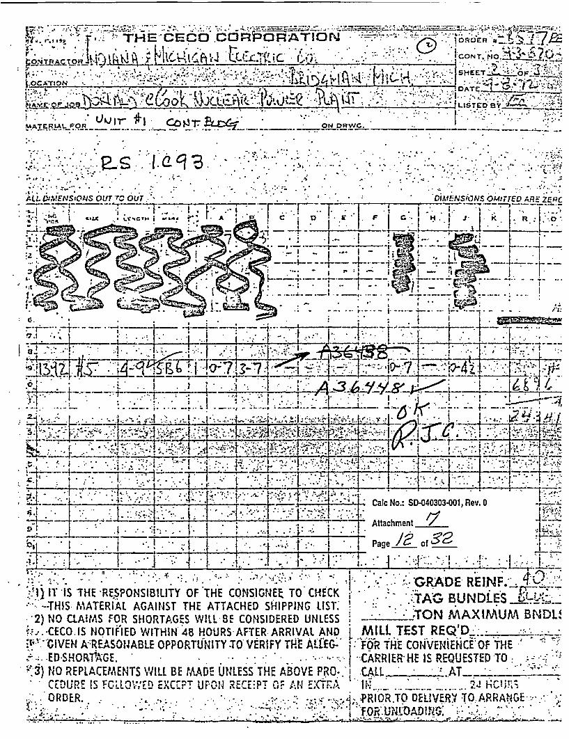
THE CEC0 COFRlQRAT0N ORDER.
I . . .SH E , _.
WATE,;^Lf OF08 I f 129rON DRWG .
MATERtAL FOR LhJr�i. Co�,c IocV�.. � I�*�'
**de .1 v
C.
ALZ..V3rVENSaONS OUT TC OUT
,S ,I . .I .
.. . .. . . . I
.. . . I
;.I . , 4 . *' . .,- .. *- ,
* O1MENSiONS OA4ITTED ARE ZtIW_ _ _ ................................................................................................
_ .
_- I _w_ _
I.* -.. . .
* ., S.C .5
C-1 :I
: G . I
.7.1 t! _6 L _L
. ,_ _ _ .......... . _|N___ __v_ ............................. , _,
.- ' 1' r5XG~HI ~ . I. 8~~- 1- - I '-
; * . . | . _ . ..._ -'_ . .* i- t-_1 L __
>--- -- i-4-- -- 4-.- .i
i L ' ~~~~~I' i S -' .
*-1 -- *- h\ ____veb,*-___;mL4;ej's $ 1e-LHo
0 . ,I I . .__ ...
: __ , i _ + :-_-. - , .
.. .I ,.
.. .. _ . .. . , ...I . i: I .
I5 ! - . a -
I ,i
I...:*1 .
. 5. - ..* - ,%...
4.. Z;
__, I . ... l + :-.
i.1* I-, . . r :, -� , I., - S
I' . I- ,; F f- Z-i-. ..4 ...... .1
,, .r l.. _ . .__ . ___ .............. __,_____ . ........................................... , . . .- - p � .4 � 4 .-- 4v.9'-�..-!.S1 I.' I... , . * * 1 ': '-: -' ' - -1r .,.. ,..... -.1 7:.:
4- L - . . CalcNo.: SD-040303-001,Rev. 0
; .A .. ~.....2..L * Li~i..j. I. ! - 'Attachment______
1 _I_. .. -g .i3
*~ i. . t .- ! ~ GRD REgeI.NoF.
..... .. ,... .. . .. ;
. T 'IS THE RESPONSIBILITY OF THE CONSIGNEE TO CHECK-THIS MATERIAL AGAINST THE ATTACHED SHIPPING LIST;
2) NO CLAWMS FOR SHORTAGES WILL 8E CONSIDERED UNLESSi-.-. CECO IS NOTIFIED WITHIN 4B HOURS-AFTER ARRIVAL AND
.'GIVE A.:REASONABLE OPPORTUINITY TO VERIFY THE A'f;.-ED SHORVAGE. .
N3) NO REPLACEMENTS WILL BE MADE UNLESS THE ABOVE PRO-.CEDURE IS MCiLOV,'ED EXC .T UFP04 RErE-PT OF Ar1 EXTRAORDER. . . . v.* -
I . .. ,. . ,. .. .. . .. . . .
* . ,;L . . .- __ ._
* j , -GRADE REIN.".._4 -.. .TAG BUNDLES
- :.TON MAXIMUM BNDL!MILl. TEST REQ'D _ _FOR THE CONVENIENCE OF THE
|.CARRIER HE is REOUESTED TO -CALL .
*FOR.TO DlDVERM *TQ ARRA!4E..:iii FoR:U~~lOA~i.Au N .: ... I .
i _:* 1 :_ _ XA

.- '.- -. ~ . ~ ~ . SHiiT:
* A ..* '. - 9 * ' ,TE'
' . .** .S' . - A. R -- 1 -
r t LGr _. . fl
IM ~ OSG I T 1(-Z
. +|e;r ' ,b { .u ''*"{i' ;K ' *: > -; {..~. v; ' - . ' . I p
rj< ~ ~ 4 tX~g ~-+ WT =V <__ v1• +k~ 7
"- I
S m ,!;. ' utbitat .l 4- 6 i!^.:! _ . . i -01 '
K it
-. - A -f I .. . L .*~l £ .- * Ia -gt q. SJs11 . * .-.-:_'_ *
*T h ______ _ -- -*°1-
'4 ^/ _ ji~ - 1 - 8Cab No.: SD-040303-001, Rev. 0
474
5 Page o
_t__. I *__ t l -* _ . .:'
~j*Y. i~' GADE
1) IT 1S THE RESPONSIBILITY.OF THE CONSIGNEE I- HE t:..:.TAG BUND L:E1 )UJ' THIS. MATERIAL AGAINST THE ATTACHED SHIPPIJNG LST. ; MAX;M * LS-2) NO ClAIMS FOR 'SHORTAGES WILL BE C91lSIDERED UNMESS. TON 'IAXIM* CECO IS NOTIFIED WITHINI 48 HOURS AFTER ARRIVAL AND [ i TEST REQD. L_
;;.;VEN A REASONABLE OPPORTUNITY-TO VERFY.TTHE U ;FOf TE CONVEShSL:E OF T -EED SltH9TAGE. .* .. .. . ARR HE. USTED TV:,
:.$) O XPP L-MrC-MENTS WILL BE MAD LESS THE C-i----.. CEDUJR lS IOllOWED.EXEPT UPO'N REIPTi-OF AN EXTIh.RU .i,- , -. ,.s9Y:'. -. 4.4'()I9
i; .t.J *.i ._a
E It.... £...d , O D._...

LE MQO"J7 PA i3 UN _. Cop-O . O.' AT3O
LEMONT, ILLlNOISFl
Report of CH1EMIACAL end PEMSI CAL Tcsts of ELECTRIC FURNACE STEEL i?8 REDAR
010rosca to _.Sllppinq Ntol.c*ho:! 3 d - -. CECO CORP., LEMONT, IL. .. ippingSh-o u rnr .Im..,o,
r1-/ 61
LE NO1.. - _ _
_
JAt 2519 72_ ,-
MAl l NALYSS | Slo.Test Piece Yield Point Strength In 8 * Area BendOre o. Order No. N. No. " C n. SiCut From tbs. per sq In lbs. per TeArt__ _ _ _ _ __ _ _ _ _ _ _________S isq. In. T est
C35150 ,;8 35 73 027 053 . 60759 91772 15 OK
___ C35157 ___-__ 36 68 020 044 =_== 57468 85316 16 6 OK
t A36688 36 66 029 060 _ . 53797 85569 17 7 OK
_ n
_____ .- _____ __ _ - - ._ .. .-
_ _~_ .c~ _ __
.__ _ - _ _ _ - _ _ _ . .- -- - -' -. . a _ _ _ _ ___ _ _ _ _ _
6l1ll1H+1 -_. IS == = _ _, ===

v,a* l I sJst ! r !' '-
LEMONT,. ILlUNOV;;FILE NO. If ' r
Rcpe r. of CHIEMICAL and P11YSICAL Tests s.f ELECTRIC FURIIACE STEEL ' REBAR ,JA!.! 12 'I, 721._
Charscd to
ShlnnLd ft
Sliipping !lice' ' 'CECO CORP., LEMONT, ILL. ATSF 1 68551r..o m-y-l~
MuHANALYSIS % Tensile Red. ofOmdll Noeat. Slab _ __ Test Piece Yield Point Strengthi ~ ___ Area BenidOrder to. Order No. No. No. C Mn ANALSI. Cut From lbs. per sq. in Ib3. per in Test_ _ _ _ _ _ _ _ _ _ _ _ _ __S i_ _ _ s q . In . _ _ _ _ _ _ _
_ _ _ _4 6 9 0 2 5 o Q O - - 5 4 1 9W 6 72 . 2 .. - ,O K
__ _ 36789 34 68 023 .45 -_ _ _ 6_ _ 1 8 ?258 20 Ole n!n .
V B*\x '8 t B_6745 __4 70 45. -A .. -5 -i -8 6 1 _
; , . . .
_ _ _ _ 0) C I I11_ _
~~~~~0 C)~! l ll <SX
_( o C)X
.~~o Z - -W
,IL 'Ylo hkerby ceci!,f 1ti3 f p ~ . ~ , * r c t a s c o n tc i ne ld In
-. . .' Zt. '.* @.. ...... ... ...
I~ 1h* cbIvz ftogurs .we cor. < 7 vnho records of tfio :I ,-
J ; . *.. , : .. S. * . .. ...i;
.* . . . i , . . . ,* . ;. <. * i *. ;,* .
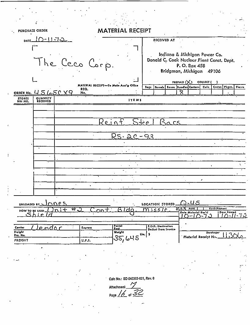
MATERIAL RECEIPTPURCHACE ORDER
DATE I (-) I I '7 -
--1RECEIVED AT
Indicna & Michigan Power Co.Donald C. Cook Nuclear.Plant Const. Dept.
P. 0. Box 458Bridgman, Michigan 49106
-T � e-- Ce-Q-'o (2""Ir ' -P
L
ORDER No. L) S: /,,IT V 'Q
2MATERIAL RECEIPT-To Main Acct g Office
REQ.No.
PREPAID |(,) COLLECT I I
Ea:i Batrls Boxes |Bundles Carlonsl Coilr Crates Pkgei. Pio-as
I I I I I I I ISTORES CUANTITYBIN NO. RECEIVED IT E M S
UNLOADED BY - r r LOCAION STORED (~IHOW TO BE USED ._ .LT. i t
.< A ;e PC r-s+± r H d m -ss le S - PAt? I I r fin-I.Shi-en;
- .5sj
DOt* Matertil Rtc'd
I) - I n--7 .0I Doi# Fasred
I Ic(-I- 7YF. O.C. Deslinalior
Carrier / )PAnItl r I Express 1 rorce,9-
FreightPro. No. I
W&tght
FOXC DestinalionDeduct from Invoke
0Q 5 $SI reiec;7er r N L _ . .
* Malorial Receip~t No. ! -J ....sFREIGHT U. P.S. IS 15
. _,
* Calc No.: SD-040303-001, Rev. 0
Attachment
Page k of g 2

*C *. : .*
* - a - 3 E ,:: :_.. : : r
Company Cho.-,Cd*
No j 0 C-Coca Stece
C t T.-r - )Th -,R
;. Y_ E I I'
' .-- .=::.;; ~<.J C.: DELY. 0RiER 70R14 4-/C ncv. A
~I 4-Coco r:action p * _7
Par 7T rNc INiGm.e l . &a I ichi--5i Eloctric C vm.
Address E:' irt6 (D.5. Cool ! .Thuc2r.o Yi
City fRid r',m _n State *Lich
r -- -A didrss
city -
-
State c
DrSCR IPTtON *COSTING DATA. _ _ I - I - - I
CON., *ENS ARTICLES
I ! ( "2 1 | NORDER NO.
oDISTRICTI PRODUCTf HARGCE1 CODE
_ J j a'. . I ,
:qbs;:Ci.Soc t-btL 211 9-3-870- -,-,7f4 0m-., I
- - . !. - - a- i . , 1. ! ; ______
__II .1 _________1 ___-
t
4II
C. 0. D.
.. . ._ ' ...
& _
'I
I .r
VI ; UAd 6A,-Ž4
Material Roceci By A Y /
zf2 Conzignoo accepted goodz without cxcetion.
3 Consignee took exception. See otfler zido.
t .
I-
L
- Cale No.: SD-040303-001, Rev. 0
Attachment
PageZ2L Of 32

*. S.;- _ .: --- … _-= ; .' :.. ::P:V rai
Copar., C%.cce'd
- j;. C.Ccco Stccl a 4-Coco Eroction
^vW,.<-T I:OEg3 tc' .c 1-ll;ana Z: lEc'n03.-,-)n0
, .css ° A c'ross e-; j'16 (D.C5. C
;_Ci;__ Stcc _ City ridmrLn
*FOAMl. CMB ftnr.*,
Dato*
Per 7_7_
E~loct-ic C.-,i-m.-ly...s
-~~~ .c- - ~, -@ -
O=SCRIPTMON *COSTING DATA
C U. CATICES ISOUCs . ARICLS L ORDER NO. HAnGE(jY CODE WEIGHT..__. , TO
.\ * . z reinforcn c61--93 -_70-. __ _|3 |. --
- '-! 1 - I6 5 9 01.!__ _ _ _ _ i3 2 . _ _~
_ _ _ _ _ _ _ __ _- ._ ..
j IIII.. j
. .
C. O. D.
C.,
':< I ;D,3.. ' ..IC5' Cmoun;'
I ; ;.- CVn)
:
RC3.it . Matcricl Rccl ad By. 3W o~w A&. n JWt .1//o
2----. -C Consignoe accepted goods wVi.:,out cxccticn :
:7J Consigneoc took cxccption. See otfc'r 'ri.
shcb of 3 0i-(!~rs Coca ______A.A
... . . ,I ..L'i~ L '- ZJ U- '''as P ac*- ' a
I "
Oa.N.: S4--.0!0::0:; .R.v.-.
5, ~ ~ ~ ~ Fl ;,t; of; . I-
- ?. .!.::.:
_ . . . . ..
: , * . . .j : ' * ' ; ' .:
*. .
-i .. . -- :
Cal No.: SD-04030300O1, Rev. 0 . .. * -
Ar~achnent ______
.. F~e <of 3c__.

*7V. r,* . I
I I - . .
I r-i I=t_=;L.' LS IA CUM .. r. . I . f-, . ' , , ,, -- ', I., I . t, §' *-_,,
CONTRAILTOR i 'd8 * i L.: 0 1 i____!. __
OCATION _. .__r x _ _
NLME OF J08 )kLh., ;. -I
ORDER I..>b (C J
.CONT. NO.n- ? ".J.;SHEET 0 O _
DATET_ .- t
L~ sr E O Y~...- .LISTED B__
CHECKED BY.UALIERIAt FOR _C ..' ./W / 5..s6e8_--
'.'d 'P ' ON DRWG._ It . 2
RA9I• /STRAIGHT BARSCOLUMN X 1 COLUMN #2
IIa NO. PCS. SIZE LENGTH NO PCS SIZE I LENGTH
GRADE REINF.
3. 4.1 _ - st3 r3-t oVX I__
5. LL1 { 7's < T3;--7v
6.-o r_ _ _ _ ______ _ 4.. . .._._._._._ __ __.
4. 4
9-. _ _ _r _ _ _--- --
I_.. ,___ __. __ dt. . i 1. 9. i
3t. __
_. ______ ____ ______;__ _ _______ I_ ___ ______ __ .. _ ._
4> I l.
e. __ ,L= _ __ I1_ 2 _! ____
_. _ __ __ -_ _ -
1. -A"J I 4t<o js , . 9v
3 . _ _ _ I. _ _ _ _ _ _ _ _ I _ _ _ _ _}
I- ] * -d - - - --- - i
6. I7XV i2 II2- 4' -
_ _ \ -_ _ _ _ _isIa/ O 9 O O __
TAG COLO- __.' _
MAXIMUM BNDL'S . _ TOIMILL TEST REQ' _ . _ _ _.
FOR THE CONVENIENCE OF THECARRIER, HE IS REQUESTED TOCALL. --- AT..IN ._ _ 24 HOURSPRIOR TO DELIVERY TO ARRANGEFOR UNLOADING.
1) IT IS THE RESPONSIBILITY OF THE COr.SIGNEE TO CHECK THIS MATERIAAGAINST THE ATTACHED SHIPPINiLIST.
2) NO CLAIMS FOR SHORTAGES WILL BCONSIDERED UNLESS CECO IS NOTIFIEWITHIN 48 HOURS AFTE It; .il - r:
AND GIVEN A REASONABLE OPPO.<.TUNITY TO VERIFY THE ALLEGED SHORIAGE.
3) NO REPLACEMENTS WILL BE MADE UNLESS THE ABOVE PROCEDURE IS FOLLOWED EXCEPT UrPON RECEIP T OF AlEXTRA ORDER.
I
9. V I; -- Z I ' I-
0.
! I IIIo I
_1 . I- Cac No.: SW.403G3001, Rev. 0
I- Af!achnment ___
e--Page -C ---of
.1 . i
I I
---- I- Ii; - I

-OCA1TION Rltrt v l*t 44AE F O At *,t _ '-.} ;X
~ ~~v~ j.: .w\\I -
IU tj< L V t: J " i_ _
CONT.NO. 14 f
SHEET _ OF 4_
DATE - : - .LISTED BY ..--
()JY -;V -'7 17, ' 1' - ON DRnWGrAATERIABL FOR_ -
,flf.ss £Z__ �lr -�
/2 Z? c-
Ii I I
4.
1) IT !S THE RESPONSIBILITY OF .THE CONSIGNEE TO CHECKTHIS MATERIAL AGAINST THE ATTACHED SHIPPING LIST.
2) NO CLAIMS FOR SHORTAGES WILL BE CONSIDERED UNLESSCECO IS NOTIFIED WITHIN 48 HOURS AFTER ARRIVAL ANDGIVEN A REASONABLE OPPORTUNITY TO VERIFY THE ALLEG-.ED SHORTAGE.
3) NO REPLACEMENTS WILL BE MADE UNLESS THE ABOVE PRO-CEDURE IS FOLLOWED EXCEPT UPON RECEIPT OF AN EXTRAORDER. -
I
III
I
GRADE REINF._ 40TAG BUNDLES____
______TON MAXIMUM INDULMILL TEST REQ'D_FOR THE CONVENIENCE OF THECARRIER HE IS REQUESTED `OCALL. _AT_ .IN.. _ _.___ L4 HI C.,
PRIOR TQ-DWl.VERY TO ARrR4A:' g.FOR UNLOADING.

* r.*, -- , * . t - - .... I .s
M. A: * ...T C1 R - 2r3A
M X !.t., r;
r.AA,/I * , : ''
CECO Cpr, P., L! 1.0 IT, I LL. A F _6_, .2oAT SF 1 6^5U"el-... . ,r.
zr No. Orcto ~ .- .Test Pieca Yield Point S~rznigih f..5L a BenC NOrder lo. * rCt From lbn. per sq. in Ibs. per n - A. R, Tcst- U * P S-'" - ~I________ sq. In. a
_ ____ 37 73 020 037 =__ 57371 884G1 16 _=O_
c34513 4 0 7 5 025 75 56AuA069 81730 18 OK
C3176o 39 83 022 _46 ._i_._57371 89743 17 _ OK_9 /_3_ 87 018 _____- 55128 80769 i8 OK
6 $ 40 75 024 054 54487 89423 1 6 OK
. - 1- ----- ' ' '-------'''
o_. . I __:__ _ _ . . .
'3 _
I
. I
I
.I
.,I
. Is
/ | ~WO 1crw.'7 ccrtli that t':m ctove ficuros am>rert an cntsl~recd In tho rcnrds of gtha coAP::
-= I ' ., j
* -* '** . _ . , * . _ _ .)*-s, ;'*- . . , , '

I.EhIONT, ILLINO 1
.. , ' r-1 Ia., ''-'-t'-' >t -i- of _ EZqTI R FURNAJCE ,'SPEr1-A, 5 ; _ :-,. ..,.. :v, P... e3G _.11 .." .
FiL) --, -C~. 7.-; / ..I: *.. -
.E HO. / __ ______
01.j J 31 ? 1c>_19- .
.. tv, S11ipT!.:1C Ntotico
nr- t! .1 ECc-CO CORP ., LE10.1O.OIT, I LL. ATSF 1 60675
far ill ct I Slab T eIS So . - t Plece Yield Pont ESWg. Red. of BendIII~O~ e tic-ato -- r ng l in __ __ A rea egOrder N C Mn P' S Si Cut From Ibs. per sq. Ir.. Is. per Tcst
______ A30G', ."11 37 70 021 047 50320 °2692 22 OK
_ _o37 C 37 70 023 048 - -= 5Q3641 8404 1 5 1 7 OK
- P B37706 37 70 014 028 5_ 3525 8383 012 17 OK
( _A37168 35 73 016 037 - _5___ __ 84615 1 8 OK
0__| A37G35 37 73 022 0 4.5. 50320 85897 1 t OK
. 0 == - . ...---- -- _
C)
l r.
|. __ - ._._- __

* '.a .*.. .%w . ...... . . . . . . 1. .. . . . ... .. . V. , .. "" , , _." P.... :. -. . .. , ... , " t.i" ;� .,: I � . . . . , , z .4:n. T, .1 iM � i :) - '. t: :�, ,.;. ,- 11 L' 12 ". !i i 1-: - I - -t --k .. , .I1.44 i kj I i'. !-;, , .. , i IX.2 AA.V 9�.X I - J ,,..iF b '.
I. TI lLLI 4c.); i
4 . . . . . . . .. ........... . . .
O. - . . .. .
;'.1 i" 1 :-'l, 7 re
FILE l41
riof C~Ct:. ~Y !. CAL Tc-t V cid. t._. S. ! .. . t _BECTRIC TUVAE ST'
ed t;a
,!'1 1 RDfA. R'I �
t.
CECO COBRP 3, L.EM.iONT, I LL. hAT 1 6P522A1AYI 17, Te unr*.:rcr.e
r__ _ _S -I _. . . :-: _____________ __ __ -r __________ -=_ =
rNo Mill Heat Slab ANALYSIS S Test Piece Yield Point Strength El-pg. ReJ. of Bend*r o. Order No. No. flo. 'C Mn P S Si Cut From lbs. per sq. In. Ibs. pern Area Testsq: n. T
A_ 3A335 0 i11 38 87 018 038 . 55128 80769 18 OK;____ B:37340 37 79 025 049 5 51602 83012 20 0I(
_ _ B37160 b 38 73 025 Q08 5447 H 3 1e17 OK
LI.
CD a P
oe? heey certify thot II.'. cbava figures ar c cctcascontained in the racords of iho compa!
. , .*: .. .
- ..o . . . . !
Ik
t...

'. n ; :tSt. rA L v t N _ r ;i4w-wle 0l -. w . , ;y~ ........ .
A\ a
A. *~w - i._FILE tIO. _
A ,.C ,,# _ .. :C ;-... :~ b *~ :.:AL m~ ' fECTRIC c. S Q _____ R. A.
:il.d ic. -
Pr- 0. t. fIPP I ,rM .lT III - P.T C -1 AO, ,
ANAY S- _ _ _Tensile El __. o fAlobLYSIS Test Piece YielJ Point Strength n_ _fn_c. tb. Order 14o. 14o. 14o. C c P SCtst From lbs. per sq. In lbs. per % % Test
. _P_ __ _ __ ISq. - Te'_B37097 #11 39 72 018 _. 042 5 54807 89102 21 OK
_/ ( 63 38 76 01' 04T . . . ~5769 85576 19 _ _ OK
A36682 4Z 37 78 021 041 5 52884 84935 16 K_ K
- 0I'~ __ ___ __ ._'== =..= =,
CD
,oI C 1 .. = * =_ ......... ... . _ . _ .
i
P
I.
, I
II
I .
. I
LhYere certify that t!0o r1oovo fgureg arecap.,, C
I as contatnod In the recordt o1 the cupat.
;
-Il

1.. '
PURCHASE ORDER
T I (-E )*-
MATERIAL RECEIPT
I a -1 ,n
rh-Thkq- e-Q-0
2
C-p .
RECEIVED AT
Indiana & Michigan Power Co.Donald C. Cook Nuclear Plant Const. Dept.
P'. 0. Box 458Brldgman, Michigan 49106
PREPAID cxC COLLECT I )
I*':
J* MATERIAL RECEIPT-Te Main Aect'g Office
REQ.Bags IBarrels Boxes jBundles Cartons Coils I Crates I Pliges. Pieces
II I I I I I I Irt LI C'/ r { f, srOKUR K 1740. IxD - t reg. j I II .
STORES QUANTITYBIN NO. RECEIVED ITEMS
.3 Ma..... acd j at Passed
'~~ IS---qbl
F.O.B. DestinationCarrier ( JEP rnrl -i r- I Express rarcel
I 0-6
FreightPro. No. I I
Weight
F.O.IB. DestinationDeduct from Invoice
Lbe$S storsok-pc
Material Receipt No. I I 3QFREIGHT IIU.F.S.
;'
Calc No.: SD.040303-001, Rev. 0
Attachment
Page C), of3

;. X . I.. -
---------------
- . -- : -- : = T -' A i 3 ? . U CA DELY. ORDERFOnl 47C REV. 4
5 S ia Coripcny Charrd*.>r . c : . ;; =0 O.Ccco S-too = 4O.Coco Ercction
Doto * _ / ___
Por '
T0
Ncme IncliduIa L bliclh&itn Elccetrc Copran- IAddross E-it ,'?i6 (D.c- , Cook ITuc24ar ?iarA)
cIt .. State * City Bid FtIa _ Stu.., _:ic:,:
.1
I. .. .
Ij,.A
!-t'.I
Calc No.: SD 040303001, Rev. 0
Attachment /Page 2 of -

';';zj z* ''- D L .' *ODER
3, t ̂ 2 Com.pcny Chorscd* '
0_ . O.Ccco Sccl I 1 4.Coco Erection
Fonxi 4-/C F'CV. t
. Data * /2 / __7
Por*#0P _'_. tr- .cn
Xom c Lcrn 5i,. T Ncmko : ∋. & Iicllm.rn Elhcebzc CG-;7...:-
° Addrcss E-1t ,'6 (D.C. Co'ok Iuc. ' 2z,)A irc::
State City B-idrman State -i' ' t1S'
DESCRIPTION * COSTING DATA
I~~. CON I rd E .1cOTRICg PRC:)UCT_KGS T r ARTICLES * T ORDER NO. T 1 WEIGHT
_ B -s- z '3,e6- !1 _ _ 9-3_870-e_ ___ _ 3_!
__1___________ |31~ a. .___ _x3LL *le;____;/
I - I _ _ _ _ _ _ _ _ _ _ _ _ _ _ * _ _ _ _ _ _ _ _ ___ .I i__ _ _ _ _ _
__ , . . 1 - ._. _= __-:_
-! Jo-t ztc=- 6F64655901
, * . I II~~ o i ~ ~ c : 2 : o ~ ~ c -~ ~ , ;* .... . . _ _ _ _ _ _ _ _ _ _ I _ _ _ _ _ _ _ _ _ _ _ _
. . 0. D.
2-. mu-
;: ; 3D
F|rnor:kG f1' J!I ~. _ _. _.
MGtC Il Recc-8yC a.Y.ST "" " .w.r.- Co ., .:
P $-oTa¢'-,> .4 V , a.
Consirnoe accepted goods witmcut a~copxion
Consi gnee took cxccption. See othzr side. .8 .. ... ::., .... .-
... ...
* * - . , ' * ** . ,:~ lt3C, , c 4 h
* � o�' � .4* *�. .-... S ** .
I... .5
rr.. .- ?-
%Pc *. . .
C. -.
E&-. -- ,- -- of . .
A-
Coco OrCd i7r 4 ..7 f -'t -
i 013a *.
. ,
1 ..
S'.X-g O ', /
Calc No.: SD-O
Attachment-,
Page•t.. 0
*..
. * .. ,* ....
40303-001, Rev. 0
7.5fZ
A1
. I
. .- 11

I*..r.."". I Mt= Lt=UJILiJ te I EL.Su
__ *. \f, 11 o\ Q . <;' l! C, ~1" I, Li J'. I '- I. I 121 I r ; Il r
, .. ).ONTRACTOR j r\l ,I { 'i rl'. -*-'-' -
OCATION * . L. *)•..... I L.. _I JOB F
ORUEL t_ * - -
CONY. NO. - ;_ _ .. - . .. 4
SHEET-1 OF )
DATE ..q 1 t .! '-
LISTED BY -
CHECKED BY_ .__IATER IL FORd IC _)_ .Ew _ _ _. ._ ._ a_._ A: _ _ ___ _ .
'. Si, STRAIGHT BARS_ , - _ _ _ . . .
COLUMN tl COLUMN t2
0 PCS I SIZE I LENGTH
-1 ..r ,..,-t.
3.'4 V -
6.1 i' I
NO. PCs SIZE LENGTH
I .� 4-I I GRADE REINF.TAG CO.LOR_
ej -%
* eI a I1.
w MAXIMUM BNDL'S.._. TOTI MILL TEST REQ'I I--I I _.
----- 4-- F- I . ___
.E-- I I I
_.._.._, I .
7.
1 8. 3 I 1
i~i 1L 2.- I c 5 _9 .4 ---
1-t - _ _ _ _ _i- = _ _ , _ ._=
... . _ _ ! _ _ .I - I - _ _ _
4.1:.
' __ -_ ',r __ --.- ~.______ ._ __ ._________ _______ _._____ ___ __________
15.;
20.
22.
23._9
24.
25.
26. <_ 6<
4 -1 /29.1 _ \ ._ _ ________, &
FOR THE CONVENIENCE OF THECARRIER, HE IS REQUESTED TOCALL._ AT_ ....... _IN ____ 24 HOURSPRIOR TO DELIVERY TO ARRANGEFOR UNLOADING.
I1) IT IS THE RESPONSIBILITY OF THE COtSIGNEE TO CHECK THIS MATERIPAGAINST THE ATTACHED SHIPPINLIST.
2) NO CLAIMS FOR SHORTAGES .WILL ECONSIDERED UNLESS CECO IS NOTiFIEWITHIN 48 .HOURS AFTER APRRV;.'AND GIVEN A REASONABLE OPPO!TUNITY TO VERIFY THE ALLEGED SHORAGE.
3) NO REPLACEMENTS WILL BE MADE UiLESS THE ABOVE PROCEDURE lS FrCLOWED EXCEPT UPON RECEIPT OF AEXTRA ORDER.
Ca1c No.: SD-040303-001, Rev. 0
Alachment Z__
pace _ of 3
32. Ck,1)AX 1� J
0 - I I.,. I.
?2-"AUL-
-
-I
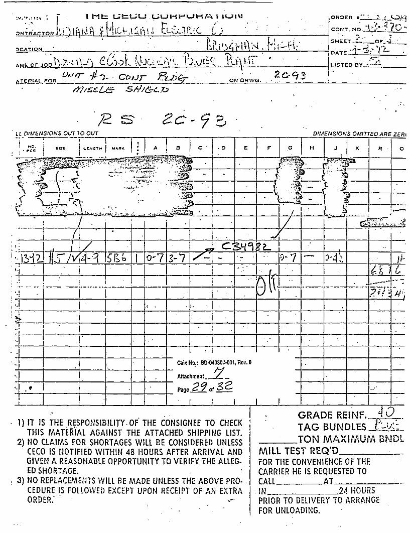
I:v."s '.-. | t= La;=LaJ {_Qb-t|X t
:)NTR'ACTOR,-,J*I !:<
DCATION _K.
AVME OJ OBn' .tCeiLA-) m^ .f ';t 1 r (. L i
O R D E R st _ J.. k_** 1
CONT. NO.- _ _
SHEET.-_OFP.4. *_
.A * :~ . I -DATE t $ _
A-.'LISTED BY ~~_ _ _
ATERtAL_ FOR i. I.-- %-W"/ ON ORWG.
LL:2, -S 5'7/&Z.' 7,
LL DIMENSIONS OUT 70 OUT_-. T-
*NO. SIZE LENGTH MARK
I-.
** h , >
,�?c - � �'-4--l
1) IT IS THE RESPONSIBILITY.OF THE CONSIGNEE TO CHECKTHIS MATERIAL AGAINST THE ATTACHED SHIPPING LIST.
2) NO CLAIMS FOR SHORTAGES WILL BE CONSIDERED UNLESSCECO IS NOTIFIED WITHIN 48 HOURS AFTER ARRIVAL ANDGIVEN A REASONABLE OPPORTUNITY TO VERIFY THE ALLEG-ED SHORTAGE.
. 3) NO REPLACEMENTS WILL BE MADE UNLESS THE ABOVE PRO-CEDURE IS FOLLOWED EXCEPT UPON RECEIPT OF AN EXTRAORDER. -
GRADE REINF.__S '~ .
TAG BUNDLES S7TON MAXIMUM BNDL
MILL TEST REQ'D_FOR THECARRIER
CONVENIENCE OF THEHE IS REQUESTED TO
CALL AT _ _
. IN ._ _ 24 HOUR'lSPRIOR TO DELIVERY TO ARRANGEFOR UNLOADING.
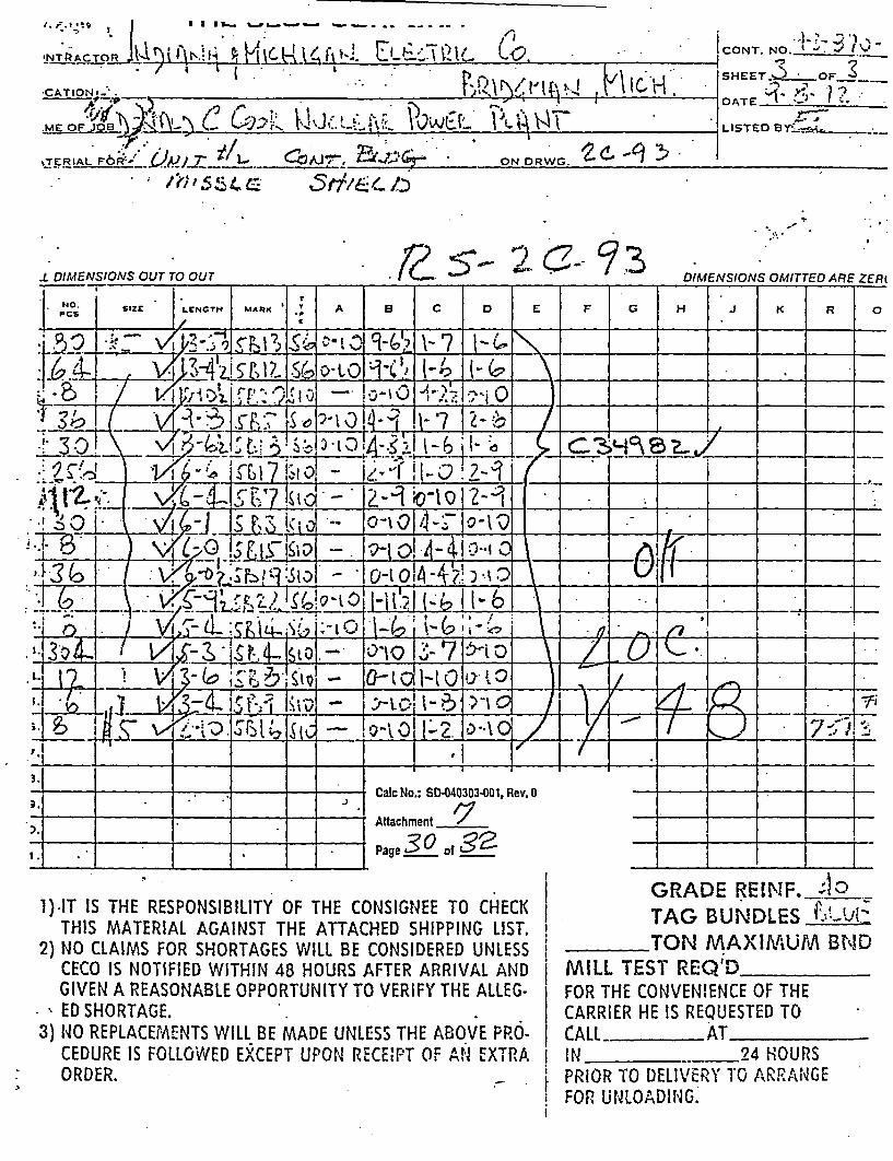
I I - - - - - - -- -
CONT. NO. t m; -.
SHEET. * OF 3_
DATE " 'i h
LISTED Bid _
ON DRWG. 'd- -9 35.
.5-- 2 C_- '73
I.
1).IT IS THE RESPONSIBILITY OF THE CONSIGNEE TO CHECKTHIS MATERIAL AGAINST THE ATTACHED SHIPPING LIST.
2) NO CLAIMS FOR SHORTAGES WILL BE CONSIDERED UNLESSCECO IS NOTIFIED WITHIN 48 HOURS AFTER ARRIVAL ANDGIVEN A REASONABLE OPPORTUNITY TO VERIFY THE ALLEG-ED SHORTAGE.
3) NO REPLACEMENTS WILL BE MADE UNLESS THE ABOVE PRO-CEDURE IS FOLLOWED EXCEPT UPON RECIEPT Of ANr EXTRAORDER.
GRADE RElNF. ar40TAG BUNDLES iu-zTON MAXIMUM B.NID
MILL TEST REQ'D _ _D-
FOR THE CONVENIENCE OF THECARRIER HE IS REQUESTED TOCALL AT_IN _ 24 HOURSPRIOR TO DELIVERY TO ARRANGEFOR UNLOADiNG.

* ~FILE NO
.-' .,. I /*
. ._. * } v .
72, , * ,* , , ,,*,.- . .. .cw _ . . . __. .. .5*¢$ ~ l -' '' ' 'r 't Ell~ lR3C ';IP'. ,C. , :r:; ,., 1E , JAti 251Q
CECO CORP., LEI-)OlT, IL. A le l bU- 673fur zb.$.r
:-
AA S Tensile Elnpg. Red. of . _dAON til HeaALYSIS SbTest Piece Yiold Point Strength In E; ' Area BendOrder No. No. No. C M P Si Cut From lbs. per sq. In. lbs. per n Test
C___ __ __ _P .__ __ __ __sq. In._ __ _ _ __ _ _ _
. C35150 35 73 027 053 60759 91772 15 OK
_ f _ __ 36 68 020 044. 57468 85316 16 OK
, A3 6688 - 36 66 029 o60 53797 85569 17 . OK
t ~~t W C)2tAII
* m z . .. ... ,. ~~ _ _. .-.
I~ ___ __ __ .__._..-.+Ib
.=
1*I
1..
Io h 7raby certify thSt th e :4VO Jguror ero ar-t- -. - as contained in the records of the compaon
"" -*- li',by Ce't^'y thot ~- ' ~: ':-' '*' e ':

ia g5- - ; " P, . - .3. n . " -t I '. -' .4 * r. ! 3 a, .
I.4E41O]1T, ILLINMOIS41 #/ > -:>FILE 110.
E rr: !04 in ' ' I i.r s rs of" #5 REP'l.;t JAMt' 14X 97. . .
Shipping oticeco CORP. ,. LEMONT, ILl . ATSF 168336
nr,= ?.: t r-.r I lqli..drrder doeMil No. t Slab TetPeoYield Point Sirength. nJL Area (end
r'No Order Lo. _s.i No. C Mn A SI -i% Cut From lbs. per sq. In Ser Tests q:_In._ .__ ._ s I T_.
__ 34930 - 27 76 019 040 58709 79677 22 .OK'
Il _C3_ 9 __2: _ 34 63 019 035 57741 79354 21 OK
A6_38-O 33 70 020 044 . _9O32 90322 18 OK
448 L| 65| 021 045 58o6 178709 2L OK'
-a > 0
. Ikb 2 fh
a0
1=1°CCa
1nE!
Mw
k
-- - - -
t
' i
__ _IZ _ L_ _
_ L I..-L
- J _________ L.L.LL.�..J.........! _____ I __________ - I _________ ______ J _______ 4._ S
/ 2
.. *.*
_ __
We hereby certify thor the above figuros ore cor.rect as contained in the records of the compony.
. .. . . . . .
I
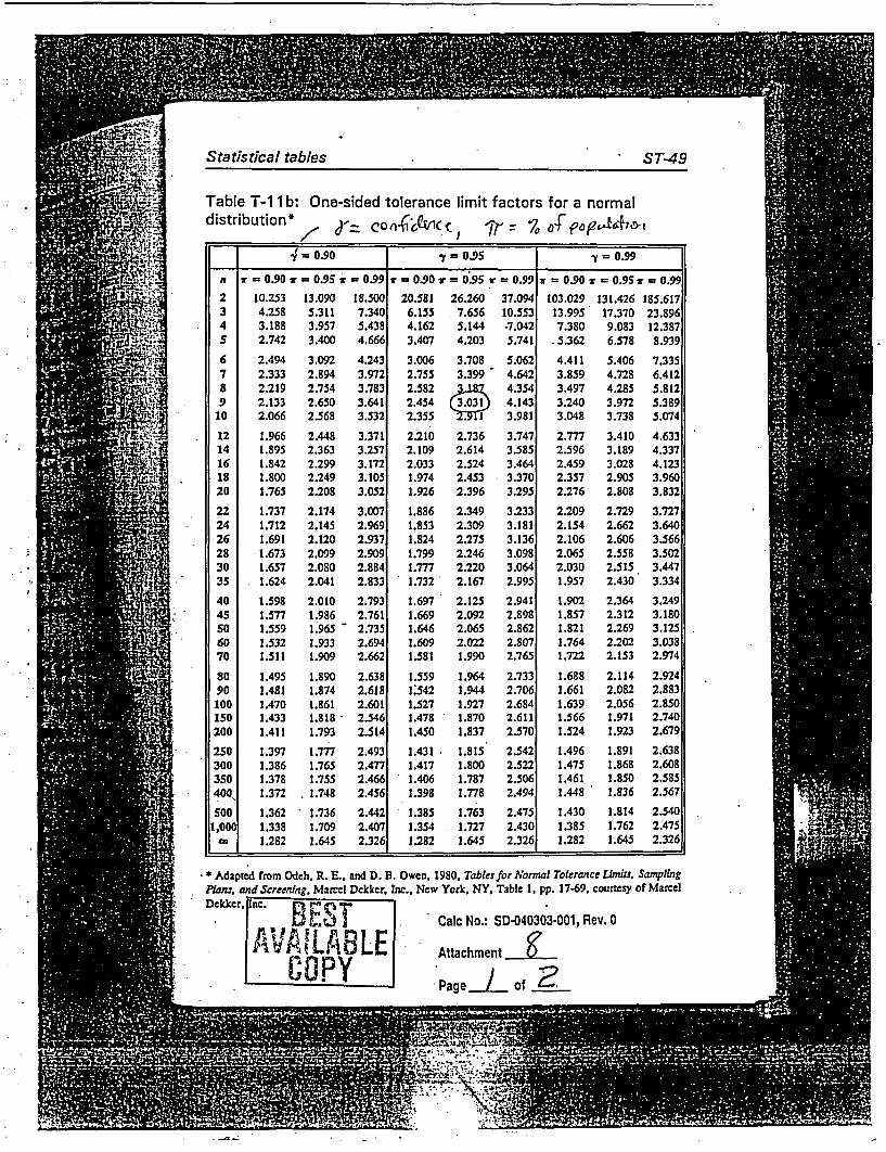
Statistical tables ST-49
Table T-1 1 b: One-sided tolerance limit factors for a normaldistribution* o d-6 c ,r-cCW , 7 of 7
0.90 Y = 9 5 =
n = 0.90 =.95S= 0.99 = 0.90r = 0.95r = 0.99 = 0.90 =0.95s= 0.992 10.253 13.090 18.500 20.581 26.260 37.094 103.029 131.426 185.6173 4.258 5.311 7.340 6.155 7.656 10.553 13.995 17.370 23.8964 3.188 3.957 5.438 4.162 5.144 .7.042 7.380 9.083 12.3875 2.742 3.400 4.666 3.407 4.203 5.741 5.362 6.578 8.9396 2.494 3.092 4.243 3.006 3.708 5.062 4.411 5.406 7.3357 2.333 2.894 3.972 2.755 3.399 4.642 3.859 4.728 6.4128 2.219 2.754 3.783 2.582 4.354 3.497 4.285 5.8129 2.133 2.650 3.641 2.454 C3.031J 4.143 3.240 3.972 5.389
10 2.066 2.568 3.532 2.355 S If 3.981 3.048 3.738 5.074
12 1.966 2.448 3.371 2.210 2.736 3.747 2.777 3.410 4.63314 1.895 2.363 3.257 2.109 2.614 3.585 2.596 3.189 4.33716 1.842 2.299 3.172 2.033 2.524 3.464 2.459 3.028 4.12318 1.800 2.249 3.105 1.974 2.453 3.370 2.357 2.905 3.96020 1.765 2.208 3.052 1.926 2.396 3.295 2.276 2.808 3.83222 1.737 2.174 3.007 1.886 2.349 3.233 2.209 2.729 3.72724 1.712 2.145 2.969 1.853 2.309 3.181 2.154 2.662 3.64026 1.691 2.120 2.937 1.824 2.275 3.136 2.106 2.606 3.56628 1.673 2.099 2.909 1.799 2.246 3.098 2.065 2.558 3.50230 1.657 2.080 2.884 1.777 2.220 3.064 2.030 2.515 3.44735 1.624 2.041 2.833 1.732 2.167 2.995 1.957 2.430 3.33440 1.598 2.010 2.793 1.697 2.125 2.941 1.902 2.364 3.24945 1.577 1.986 2.761 1.669 2.092 2.898 1.857 2.312 3.18050 1.559 1.965- 2.735 1.646 2.065 2.862 1.821 2.269 3.12560 1.532 1.933 2.694 1.609 2.022 2.807 1.764 2.202 3.03870 1.511 1.909 2.662 1.581 1.990 2.765 1.722 2.153 2.974
80 1.495 1.890 2.638 1.559 1.964 2.733 1.688 2.114 2.92490 1.481 1.874 2.618 1:542 1.944 2.706 1.661 2.082 2.883100 1.470 1.861 2.601 1.527 1.927 2.684 1.639 2.056 2.850150 1.433 1.818 2.546 1.478 1.870 2.611 1.566 1.971 2.740200 1.411 1.793 2.514 1.450 1.837 2.570 1.524 1.923 2.679
250 1.397 1.777 2.493 1.431 1.815 2.542 1.496 1.891 2.638300 1.386 1.765 2.477 1.417 1.800 2.522 1.475 1.868 2.608350 1.378 1.755 2.466 1.406 1.787 2.506 1.461 1.850 2.585400, 1.372 . 1.748 2.456 1.398 1.778 2.494 1.448 1.836 2.567SOO 1.362 1.736 2.442 1.385 1.763 2.475 1.430 1.814 2.540
1,0 t 1.338 1.709 2.407 1.354 1.727 2.430 1.385 1.762 2.475_ 1.282 1.645 2.326 1.282 1.645 2.326 1.282 1.645 2.326
* Adapted from Odeh, R. E., and D. B. Owen. 1980, Tables for Normal Tolerance Iimits. SamplingPlans, and Screening. Marcel Dekker, Inc., New York, NY, Table 1, pp. 17.69. courtesy of MarcelDekker, pnc. F.
Calc No.: SD-040303-001, Rev. 0
Attachment
Page l of 2
k - * . - :7 1

ST-48 Applying Statistics stat
Table T-1 1 b: One-sided tolerance limit factors for a Tabinormal distribution distr
Statistical tolerance tlimits are values derived from sample data in such a manneras to encompass a specified fraction of a population's values and to do so with aj prescrbed level of confidence. Table 11-b provides the factors needed to 2produce one-sided lower or upper bounds from samples of size n of normally 3
distributed variables. Factors are given'for three fractions-or = 0.90, 0.95, and 4
0.99-and for three levels of confidence-y = 0.90, 0.95, and 0.99. For other 5combinations of n, xr, and y, refer to Cideh and Owen (1980, pp. 17-69). 6
7
Because statistical tolerance intervals are functions of the sample's mean and 8standard deviation, the intervals themselves are random variables: they change .9their calculated endpoints with each new sample. But, because of the nature of 12their construction, 100-y% of them will contain 100r0% of the population, from
16which their samples are drawn. 16
20Example 1: Consider a sample of size n = 10 that yields x = 143.2 ands = 13.9. To create a one-sided upper interval that contains 90% of the | 22
.population with 95% confidence, turn to Table T-llb. From the three columns 2426headed by y = 0.95, find the column headed by X = 0.90. At the intersection 28of that column with the row labelled 10, note the value k = 2.355. The 30
interval's upper endpoint is found by calculating x + is = 143.2 + 2.355(13.9) 3£= 143.2 + 32.7 = 175.9. Thus, with 95% confidence, the interval (-co, 175.9) 40
contains 90% of the population. ' 455060
Example 2: Consider a sample of size n = 10 that yields x 143.2 and ' 70
s = 13.9. To create a one-sided lower interval that contains 90% of the sopopulation with 95% confidence, turn to Table T-l lb. From the three columns 90headed by y = 0.95, find the column headed by ir = 0.90. At the intersection 100of that column with the row labelled 10, note the value k = 2.355. The 200
interval's upper endpoint is found by calculating x - = 143,2 - 2.355(13.9): 143.2 - 32.7 = 110.5. Thus, with 95% confidence, the interval (110.5, -oa) 300,
- contains 90% of the population. 3. .350400i
* 5;T p) _d sr e ̂ ; .So
AdarPlans,
CalcNo.: SD-040303-001, Rev. 0 L Dekke:
Attachment _| ak 1LEPage of

Attachment 9 - Excel Spreadsheets Used for Computations
Calc No.: SD-040303X001, Rev. 0
Attachment /
Page / of csii~

Table M2 (Units 1 & 2)
Yield Point Yield PointHeat No. Bar Size Test #1 Test #2
. (psi) (psi)C34105 #11 50,897 .52,115B37160 #11 51,025 50,833C35157 #8 51,265 50,759B36171 #11 52,115 52,692A37151 #11 50,448 50,192B37340 #11 52,179 49,487A36334 #11 50,384 49,935
Average 51,023StandardDeviation 947.04
Is
Calc No.: SD-040303 001, Rev. 0
Attachment
Page c Of o

=B |C 0 ET2 Table M2 (Units 1 & 2)3
H Yield Point Test #1 Yield Point Test #24 Heat No. Bar Size (psi) (psi)
5 C34105 #11 50897 521156 B37160 #11 51025 508337 C35157 #8 51265 507598 B36171 #11 52115 526929 A37151 #11 50448 50192
10 B37340 #11 52179 4948711 A36334 #11 50384 4993512 .1.
131 Average =AVERAGE(D5:E11)
141 Standard Deviation =STDEV(D5:E11)
151617
0 > cr0 > 2O n
CD
2 . z
cC
I CI
03 :I41
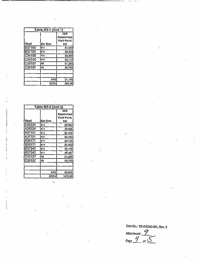
Table M3-1 (Init 11I&M
DeterminedYield Point,
Heat Bar Size psiB37160 #11 51,025B37160 #11 50,833C34105 #11 50,89C34105 #11 52,115C35157 #8 51,265C35157 #8 50,759
AVG 51,149
SDEV 505.46
Table M3-2 (U lit2)I&M
DeterminedYield Point,
Heat Bar Size psiA36334 #11 50,384A36334 #11 49,935A37151 #11 50,448A37151 #11 50,192B36171 #11 52,115B36171 #11 52.692B37340 #1 52.179B37340 #11 49,487C35157 #8 51,265C35157 #8 50,759
AVG 50,946
.SDEV 1072.65
Calc No.: SD040303-001, Rev. 0
Attachment 7Page y of (

I A I .8 I D I E1 Table M3-1 (Unit 1)
I&M Determined Yield2 Heat Bar Size Point, psi3 B37160 #11 510254 837160 #11 508335 C34105 #11 50897
6 C34105 #11 52115
7 C35157 #8 512658 C35157 #8 50759
19011 . AVG =AVERAGE(D3:D8)
12 SDEV =STDEV(D3:D8)
13141516.1718 I Table M3-2 (Unit 2)
I&M Determined Yield19 Heat Bar Size Point, psi
20 A36334 #11 5038421 A36334 #11 49935
22 A37151 #11 5044823 A37151 #11 5019224 B36171 . #11 5211525 836171 #11 5269226 B37340 #11 5217927 B37340 #11 4948728 C35157 #8 51265
29 C35157 #8 50759
30 A31 ...
33 .. AVGI=AVERAGE(D20:D29)
34 1 SDEVI STDEVID20:D29)
Calc No.: SD-040303-001, Rev. 0
Attachment
Page S of of
Attachment 10 - Normal Distribution Statistical Data Sheets
Calc No.: SD-040303-001* Rev. 0
Attachmeilt /0
Pagc _/_ of L.

W Test for Normality - 14 I&M Test Results for Unit 1 & 2Refer to Pages 7-9 through 7-12 of Reference 3q = 0.05 = level of confidence (Refer to Page 11)
Rank i Ascending Descending Difference Table T-6a a(i)[y(n-i+1)Ordered Ordered [y(n-i+l) - Coefficients - y(i)1Data y(i) Data y(i)] for K=7
y(n i+1) a(i)1 49487 52692 3205 0.5251 1682.94552 49935 52179 2244 0.3318 744.55923 50192 52115 1923 0.2460 473.05804 50384 52115 1731 0.1802 311.92625 50448 51265 817 0.1240 101.30806 50759 51025 266 0.0727 19.33827 50833 50897 64 0.0240 1.53608 50897
9 5102510 5126511 5211512 5211513 5217914 52692
B= 3334.6711
Table T-6b from Ref. 3Wq(n) = 0.874
S = 947.04n=14 N
W = (B**2)/(n-1)*(S**2) = 0.9537
W > Wq(n) , Result = Normal Distribution
Calc No.: SD-040303-001, Rev. 0
Attachment /°
Page 2 of I/

W Test for Nonnalitv - 6 I&M Test Results for Unit 1
Rank i Ascending Descending Difference Table T-6a a(i)[y(n-i+1)Ordered Ordered [y(n-i+1) - Coefficients - Y(i)]Data y(i) Data Y(i)] for K=3
y(n-i+1) 0) _1 50759 52115 1356 0.6431 872.04362 50833 51265 432 0.2806 121.21923 50897 51025 128 0.0875 11.20004 510255 512656 52115 _ _ _ _ _ _ _ _ _ _ _ _
B = 1004.4628
Table T-6b from Ref. 3Wq(n) = 0.788
S = 505.46n=6
W = (B**2)/(n-1)*(S**2) = 0.7898
W > Wq(n) , Result = Normal Distribution
Calc No.: SD-0403034o01, Rev. 0
Attachment / °
Page i of C

W Test for Normality -10 I&M Test Results for Unit 2
Rank i Ascending Descending Difference Table T-6a a(i)[y(n-i+1)Ordered Ordered [y(n-i+1) - Coefficients - y(i)]Data y(i) Data y(i)] for K=5
y(n-i!1) a(i)1 49487 52692 3205 0.5739 1839.34952 49935 52179 2244 0.3291 738.50043 50192 52115 1923 0.2141 411.71434 50384 51265 881 0.1224 107.83445 50448 50759 311 0.0399 12.40896 50759 X _ _
7 51265 _ _ _ _ _ _
8 52115_9 52179 _ _ _ __.
10 52692
I I B= 3109.8075
Table T-6b from Ref. 3Wq(n) = 0.842
S = 1,072.65n=10
W = (B**2)/(n-1)*(S**2) = 0.9339
W > Wq(n), Result = Normal Distribution
Calc No.: SD-040303-001, Rev. 0
Attachment Jo
Page C of C.

Calculation Review Comment FormCalculation No.: SD-040303-001 I Revision: 0 CS NO:Title UNIT 1 & 2 CONTROL ROD DRIVE MISSILE SHIELD Attachment: 11
REINFORCING STEEL YIELD STRENGTH Page: 1 of 1This form was completed using the Calculation Review Checklist from 12 EHP 5040 DES.003[ Attachment 3 EJ Attachment 4, Restricted Use Calculation Review ChecklistCalculation Review El Full Scope Review Ea Partial Scope Review (Describe scope in Comment #1)Checklist
Comment AttributeComment Resolution
I 4a Provide an overview of the The overview of the methodlapproach hasmethod/approach that will be used for the been provided at the beginning of Section 6.0.calculation.
2 6b The details currently provided in Sections These sections have been moved to Section6.1 and 6.2 more correctly belong in 8.0, "Assumptions & Limitations".Section 8, Assumptions and Limitations.
3 7d The details for the tests for normality are The tests for normality now appear in Sectionan inherent part of the calculation and 9.0, "Calculations".should be evaluated in Section 9,Calculations.
4 7c For the information currently in Section Additional justification for discounting the use6.1 (see Comment 2), additional of the CMTR data has been given in Sectionjustification is needed for discounting the 8.0.use of the CMTR data.
5 6a In the current Section 6.2, an incorrect This incorrect statement has been corrected.statement is made regarding CMTR datavs. 1&M test data. Not all CMTR valuesexceed the companion I&M test values.
6 4b In the current Section 6.2, the I&M test All I&M tests are now considered together.data for the individual tests from each The individual tests from each heat are nowheat are called out separately. There is no not called out separately.basis (or need?) for this approach. Thisalso applies to Section 9.0, Method 2(page 15).
7 6b On Page 8, 6.2.i, the determined strain This section was removed from themay not be correct. Elongation was calculation. The strain rate is no longer beingdetermined over an 8 inch specimen, not used in the discussion.a 36 inch specimen.
8 lid Attachment 10 graph needs to be This has been completed. Graphs for Unit 1reconfigured so that the unit specific and Unit 2 can now be discerned.
. information can be discerned whenprinted in black and white.
9 N/A Various editorial comments provided via These have all been reviewed and corrected.marked up pages.
Computations were checked by a combination of Microsoft Excel Statistical Analysis i oots and 1 1oot calculator.
Reviewed by: Print Name i / )Date,. P. W. Leonard - -& -1 I 3'5 /
I ,- 4 -~
Tbis form is derived from 12 EHP 5040 DES.003

Design Review Board Approval Form
El E-Mod, [] TM, E CALC, 2 OtherTitle of Product: Missile Block Rebar Calculation
Product No.: SD-040303-001 Rev. 0
Date: March 22, 2004
The DRB will be responsible for providing an additional level of management oversight toassure the quality of products reviewed and endorsed by the DRB.
DRB members shall pay particular attention to the aspects of the products (i.e., design input,assumptions, equipment locations, etc) within their respective areas of expertise.
DRB comments have been satisfactorily resolved and incorporated or included as open item(s) asdesignated by membership signatures OR Chairperson signature below.
Approval by Membership
Area Name (Printed) Name (Signature) Date
Regulatory AffairsConfiguration Control Donald HaferNE Electrical _ _ _ _ . _,,
NEI&CNE Mechanical . A:
NE StructuralSystem Engineering _
OperationsNuclear SafetyProjects -MMSMET .ENPIENPV -_.ESY_Reactor Engineering _
ENPMOR
Approval by Chairperson
Name (Printed) Name (Signature) Date
Paul R. Donavin _ O
Calc No.: SD-040303-001, Rev. 0
Attachment 1 2Page of /
This form is derived from Data Sheet I of 12-EHP-5040-DRB-O01, Rev. 4. Design Review Board Expectations,Policies, and Practices.