attack-aware data timestamping in low-power
TRANSCRIPT
Attack-Aware Data Timestamping in Low-PowerSynchronization-Free LoRaWAN
Chaojie Gu∗ Linshan Jiang∗ Rui Tan∗ Mo Li∗ Jun Huang†∗Nanyang Technological University, Singapore †Peking University, China
Abstract—Low-power wide-area network technologies such asLoRaWAN are promising for collecting low-rate monitoring datafrom geographically distributed sensors, in which timestampingthe sensor data is a critical system function. This paper considersa synchronization-free approach to timestamping LoRaWANuplink data based on signal arrival time at the gateway, whichwell matches LoRaWAN’s one-hop star topology and releasesbandwidth from transmitting timestamps and synchronizing enddevices’ clocks at all times. However, we show that this approachis susceptible to a frame delay attack consisting of malicious framecollision and delayed replay. Real experiments show that theattack can affect the end devices in large areas up to about50, 000m2. In a broader sense, the attack threatens any systemfunctions requiring timely deliveries of LoRaWAN frames. Toaddress this threat, we propose a LoRaTS gateway design thatintegrates a commodity LoRaWAN gateway and a low-powersoftware-defined radio receiver to track the inherent frequencybiases of the end devices. Based on an analytic model of LoRa’schirp spread spectrum modulation, we develop signal processingalgorithms to estimate the frequency biases with high accuracybeyond that achieved by LoRa’s default demodulation. The accu-rate frequency bias tracking capability enables the detection ofthe attack that introduces additional frequency biases. Extensiveexperiments show the effectiveness of our approach.
I. INTRODUCTION
Low-power wide-area networks (LPWANs) enable directwireless interconnections among end devices and gateways ingeographic areas of square kilometers [1]. It increases networkconnectivity as a defining characteristic of the Internet ofThings (IoT). Among various LPWAN technologies (includingNB-IoT and Sigfox), LoRaWAN [2], which is an open datalink layer specification based on the LoRa modulation scheme[3], offers the advantages of using license-free ISM bands, lowcosts for end devices, and independence from managed cellularinfrastructures.
LoRaWAN is promising for the applications of collectinglow-rate monitoring data from geographically distributed sen-sors, such as utility meters, environment sensors, roadwaydetectors, industrial measurement devices, etc. All these appli-cations require data timestamping as a basic system service,though they may require different timestamp accuracies. Forinstance, data center environment condition monitoring gener-ally requires sub-second accuracy for sensor data timestampsto capture the thermodynamics [4].
Sub-second-accurate timestamps for the traffic data gener-ated by roadway detectors can be used to reconstruct real-time traffic maps [5]. In a range of industrial monitoringapplications such as oil pipeline monitoring, millisecondsaccuracy may be required [6]. In volcano monitoring, the onset
times of seismic events detected by geographically distributedsensors require sub-10 milliseconds accuracy to be meaningfulto volcanic earthquake hypocenter estimation [7].
There are two basic approaches, namely, sync-based andsync-free, to data timestamping in wireless sensor networks(WSNs). In the sync-based approach, the sensor nodes keeptheir clocks synchronized and use the clock value to timestampthe data once generated. Differently, the sync-free approachuses the gateway with wall time to timestamp the data upon thearrival of the corresponding network packet. Based on variousexisting distributed clock synchronization protocols, multi-hopWSNs mostly adopt the sync-based approach. The sync-freeapproach is ill-suited for multi-hop WSNs, because the datadelivery on each hop may have uncertain delays due to variousfactors such as channel contention among nodes.
In contrast, LoRaWANs prefer the sync-free approach foruplink data timestamping. Reasons are two-fold. First, dif-ferent from multi-hop WSNs, LoRaWANs adopt a one-hopgateway-centered star topology that is free of the issue ofhop-wise uncertain delays. Specifically, as the radio signalpropagation time from an end device to the gateway isgenerally in microseconds, the LoRaWAN frame arrival timecan well represent the time when the frame leaves the enddevice. As a result, timestamping the uplink data at thegateway can meet the milliseconds or sub-second timestamp-ing accuracy requirements of many applications. Second, ifthe sync-based approach is adopted otherwise, the task ofkeeping the end devices’ clocks synchronized at all times andthe inclusion of timestamps in the LoRaWAN data frameswill introduce communication overhead to the narrowbandLoRaWANs. Therefore, performance-wise, the sync-free ap-proach well matches LoRaWANs’ star topology and addressesits bandwidth scarcity.
However, LoRaWAN’s long-range communication capabil-ity also renders itself susceptible to wireless attacks that can belaunched from remote and hidden sites. The attacks may affectmany end devices in large geographic areas. In particular,the conventional security measures that have been includedin the LoRaWAN specifications (e.g., frame confidentialityand integrity) may be inadequate to protect the network fromwireless attacks on the physical layer. Therefore, it is ofimportance to study the potential wireless attacks against thesync-free data timestamping, since incorrect timestamps rendersensor data useless and even harmful. For example, whenapplying LoRa for IoT object localization by triangulation,tiny timestamping error will lead to large localization errors.
arX
iv:1
905.
0167
9v2
[cs
.NI]
11
Apr
202
0
In this paper, we consider a basic threat of frame delayattack that directly invalidates the assumption of near-zerosignal propagation time. Specifically, by setting up a colliderdevice close to the LoRaWAN gateway and an eavesdropperdevice at a remote location, a combination of malicious framecollision and delayed replay may introduce arbitrary delays tothe deliveries of uplink frames. Although wireless jammingand replay have been studied extensively, how easily they canbe launched in a coordinated manner to introduce frame delayand how much impact (e.g., in terms of affected area) theattack can generate are still open questions in the context ofLoRaWANs.
This paper answers these questions via real experiments.Our measurements show that LoRa demodulators have lengthyvulnerable time windows, in which the gateway cannot decodeeither the victim frame or the collision frame, and raises noalerts. Thus, it is easy to launch stealthy attacks by exploitingthe vulnerable time windows. In particular, as the attack doesnot breach the integrity of the frame content and sequence,the attack cannot be solved by cryptographic protection andframe counting. Our experiments in a campus LoRaWANshow that, a fixed setup of a collider and an eavesdroppercan subvert the sync-free data timestamping service for enddevices in a large geographic area of about 50, 000 m2. Ina broader sense, this attack threatens any system functionsthat require timely deliveries of uplink frames in LoRaWAN.Note that this attack is valid but marginally important in short-range wireless networks (e.g., Zigbee and Wi-Fi) because ofthe limited area affected by the attack and the difficulty incontrolling the attack radios’ timing. Differently, it is importantto LoRaWANs because it can affect large geographic areas andthe timing of the attack radios can be easily controlled due toLoRaWAN’s long symbol times.
Therefore, an upgraded sync-free timestamping approachthat integrates countermeasures against the attack and mean-while preserves the bandwidth efficiency is desirable. More-over, it should only require changes to the gateway. In thispaper, we aim to develop awareness of the attack by moni-toring the end devices’ radio frequency biases (FBs), whichare mainly caused by the manufacturing imperfections of theradio chips’ internal oscillators. A deviation of FB detectedby the gateway suggests the received frame may be a replayedone, since the adversary’s replay device superimposes its ownFB onto the replayed signal. To access the physical layer, weintegrate a low-cost (US$25 [8]) software-defined radio (SDR)receiver [9] with a commodity LoRaWAN gateway to form ourLoRa TimeStamping (LoRaTS) gateway. We develop time-domain signal processing algorithms for LoRaTS to estimatethe FB. Experiments show that (i) with a received signal-to-noise ratio (SNR) of down to −18 dB, LoRaTS achieves anaccuracy of 120 Hz in estimating FB, which is just 0.14 parts-per-million (ppm) of the channel’s central frequency of 869.75MHz; (ii) the frame replay by an SDR transceiver introducesan additional FB of at least 0.24 ppm. Thus, LoRaTS cantrack FB to detect the replay step of the frame delay attack.In contrast, the LoRa’s built-in FB estimation performed in the
frequency domain [10] does not achieve sufficient resolutionto detect the attack. Note that the detection does not requireuniqueness or distinctiveness of the FBs across different LoRatransceivers, because it is based on changes of FB.
The paper makes the following contributions:• We implement the frame delay attack against LoRaWAN.
Simulations and experiments show the large sizes of thegeographic areas vulnerable to the attack.
• Based on an analytic model of LoRa’s chirp spreadspectrum (CSS) modulation, we design a time-domainsignal processing pipeline to accurately estimate enddevices’ FBs. The pipeline addresses challenges such asthe need of microsecond-accurate arrival time estimationfor the narrowband LoRa signal.
• Extensive experiments in both indoor and urban envi-ronments show that LoRaTS can detect the frame delayattacks that introduce additional FBs.
In summary, the feasibility of the attack and the large sizesof geographic areas vulnerable to the attack call for propercountermeasures. LoRaTS, as a countermeasure, preserves thebandwidth efficiency of sync-free timestamping and requiresno modifications on the LoRaWAN end devices. It is a low-cost countermeasure that increases the cost and technicalbarrier for launching effective frame delay attacks, sincethe attackers need to eliminate the tiny FBs of their radioapparatuses. Although completely solving the attack (includingzero-FB attack and recovering from attack) still faces extrachallenges, LoRaTS strikes a satisfactory trade-off betweennetwork efficiency and the security level required by typicalLoRaWAN applications.
The rest of this paper is organized as follows. §II reviewsrelated work; §III describes sync-free data timestamping; §IVstudies the attack; §V presents the LoRaTS design; §VI studiesLoRa’s FB and uses it to detect attack; §VII presents exper-iment results; §VIII discusses several issues; §IX concludesthis paper.
II. RELATED WORK
Improving LoRaWAN’s communication performance hasreceived increasing research. Choir [10] exploits the diverseFBs of the LoRaWAN end devices to disentangle collidingframes from different end devices. Choir uses the dechirpingand Fourier transform processing pipeline to analyze FB,which does not provide sufficient resolution for detecting thetiny extra FB introduced by attack (see details in §VI-A).In this paper, based on an analytic model of LoRa’s CSSmodulation, we develop a new time-domain signal processingalgorithm based on a least squares formulation to achieve therequired resolution. Charm [11] exploits coherent combiningto decode a frame from the weak signals received by multiplegeographically distributed LoRaWAN gateways. It allows theLoRaWAN end device to use a lower transmitting power. Sev-eral recent studies [12], [13] have devised various backscatterdesigns for LoRa to reduce the power consumption of enddevices. All the studies mentioned above focus on under-standing and improving the data communication performance
of LoRaWAN [10], [11], or reducing power consumption viabackscattering [12], [13]. None of them specifically addressesefficient data timestamping, which is a basic system functionof many LoRaWAN-based systems.
LongShoT [14] is an approach to synchronize the Lo-RaWAN end devices with the gateway. Through low-leveloffline time profiling for a LoRaWAN radio chip (e.g., tomeasure the time delays between hardware interrupts andthe chip’s power consumption rise), LongShoT achieves sub-50 microseconds accuracy, which is echoed by our resultson the accuracy of estimating signal arrival time using adifferent approach. LongShoT is designed for the LoRaWANsystems requiring tight clock synchronization. Differently, weaddress data timestamping and focus on the less stringent butmore commonly seen milliseconds or sub-second accuracyrequirements. Our sync-free approach releases the bandwidthfrom frequent clock synchronization operations.
Security of LoRaWAN is receiving research attention. In[15], Aras et al. discuss several possible attacks againstLoRaWAN, including key compromise and jamming. Thekey compromise requires prior physical attack of memoryextraction. In [16], a selective jamming attack against certainreceivers and/or certain application frames is studied. Differentfrom the studies [15], [16] that do not consider the stealthinessof jamming, we consider stealthy frame collision. From ourresults in §IV-B, the selective jamming in [16] cannot bestealthy because it cannot start jamming until the frame headeris decoded and the corruption of payload must lead to integritycheck failures. In [17], Robyns et al. apply supervised machinelearning for end device classification based on the receivedLoRa signal. From our measurements, the dissimilarity be-tween the original and the replayed signals is much lower thanthat among the original signals from different end devices.Thus, the supervised machine learning is not promising forattack detection.
Device identification based on radiometric features has beenstudied for short-range wireless technologies. A radiometricfeature is the difference between the nominal and the measuredvalues of a certain modulation parameter. The work [18] stud-ied the radiometric features of IEEE 802.11 radios, includingsymbol-level features regarding signal magnitude and phase,as well as frame-level feature regarding carrier frequency. InLoRaWAN, the received signal strength is often rather low dueto long-distance propagation or barrier penetration. As such,the signal magnitude radiometric feature cannot be used as aradiometric feature. As the phase of LoRa signal is arbitrary, itcannot be employed as a radiometric feature too. In this paper,we show that the bias of the LoRa signal’s carrier frequencyfrom the nominal value is an effective radiometric feature.This feature can be used to counteract the frame delay attack.Based on LoRa’s CSS modulation, we develop a lightweightalgorithm that can estimate this feature from the receivedLoRa signal. It requires a low-cost SDR receiver, unlike theexpensive vector signal analyzer [19] used in [18].
III. DATA TIMESTAMPING IN LORAWAN
A. LoRaWAN Primer
LoRa is a physical layer technique that adopts CSS modu-lation. LoRaWAN is an open data link specification based onLoRa. A LoRaWAN is a star network consisting of a numberof end devices and a gateway that is often connected to theInternet. Gateways are often equipped with GPS receivers fortime keeping. The transmission direction from the end deviceto the gateway is called uplink and the opposite is calleddownlink. LoRaWAN defines three classes for end devices, i.e.,Class A, B and C. In Class A, each communication sessionmust be initiated by an uplink transmission. There are two sub-sequent downlink windows. Class A end devices can sleep tosave energy when there are no pending data to transmit. ClassA adopts the ALOHA media access control protocol. Class Bextends Class A with additional scheduled downlink windows.However, such scheduled downlink windows requires the enddevices to have synchronized clocks, incurring considerableoverhead as we will analyze shortly. Class C requires the enddevices to listen to the channel all the time. Clearly, Class C isnot for low-power end devices. In this paper, we focus on ClassA, because it is supported by all commodity platforms andenergy-efficient. To the best of our knowledge, no commodityplatforms have out-of-the-box support for Class B that requiresclock synchronization.
B. Advantages of Sync-Free Timestamping
Data timestamping, i.e., to record the time of interest interms of the wall clock, is a basic system function requiredby the data collection applications for monitoring. For asensor measurement, the time of interest is the time instantwhen the measurement is taken by the end device. Multi-hop WSNs largely adopt the sync-based approach. Specifically,the clocks of the WSN nodes are synchronized to the globaltime using some clock synchronization protocol. Then, eachWSN node can timestamp the data using its local clock.WSNs have to adopt this approach due primarily to thatthe multi-hop data deliveries from the WSN nodes to thegateway in general suffer uncertain delays. Thus, although theclock synchronization introduces additional complexity to thesystem implementation, it has become a standard componentfor systems requiring data timestamping. However, the clocksynchronization introduces considerable communication over-head to the bandwidth-limited LoRaWANs.
We present an example to illustrate the overhead to main-tain sub-10 milliseconds (ms) clock accuracy in LoRaWANs.Typical crystal oscillators in microcontrollers have drift ratesof 30 to 50 ppm [20]. Without loss of generality, we adopt40 ppm for this example. With this drift rate, an end deviceneeds 14 synchronization sessions per hour to maintain sub-10 ms clock accuracy. These 14 sessions represent a significantcommunication overhead for an end device. For instance, inEurope, a LoRaWAN end device adopting a spreading factor of12 can only send 24 30-byte frames per hour to conform to the1% duty cycle requirement [21]. Although the synchronization
GatewayEnd device
Eavesdropper
Inject delay and replay
Collider / Replayer
Framecollision
Transfer
Uplink
Record
2
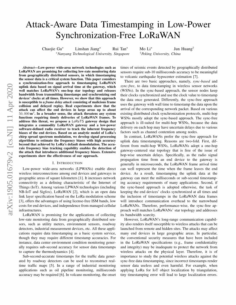
Fig. 1. Steps for implementing frame delay attack.
information may be piggybacked to the data frames, a low-rate monitoring application may have to send the frames morefrequently just to keep time. In addition, the data frames needto include data timestamps, each of which needs at least a fewbytes. This is also an overhead given the bandwidth scarcity.
To efficiently utilize LoRaWAN’s scarce bandwidth andexploit its star topology, the sync-free timestamping approachcan be adopted. In this approach, an end device transmits asensor reading once generated. Upon receiving the frame, thegateway uses the frame arrival time as the data timestamp.The signal propagation time from the end device to thegateway, which is often microseconds, can be ignored formillisecond-accurate timestamping. Compared with the sync-based approach, this sync-free approach avoids the communi-cation overhead caused by the frequent clock synchronizationoperations and the transmissions of timestamps. Thus, thesync-free approach is simple and provides bandwidth-savingbenefit throughout the lifetime of the LoRaWANs.
IV. SECURITY OF SYNC-FREE TIMESTAMPING
The long-range communication capability of LoRaWANenables the less complex and bandwidth-efficient sync-freetimestamping. However, it may also be subjected to wirelessattacks that can affect large geographic areas. Having under-stood the benefit of sync-free timestamping, we also need tounderstand its security risk and the related countermeasure forachieving a more comprehensive assessment on the efficiency-security tradeoff. A major and direct threat against the sync-free approach is the frame delay attack that manipulates theframe delivery time to invalidate the assumption of near-zerosignal propagation delay. We formally define the attack asfollows.Frame delay attack: The end device and gateway are notcorrupted by the adversary. However, the adversary may delaythe deliveries of the uplink frames. The malicious delay for anyuplink frame is finite. Moreover, the frame cannot be tamperedwith because of cryptographic protection.
The attack results in wrong timestamps under the sync-free approach. This section studies the attack implementation(§IV-A), investigates the timing of malicious frame collision(§IV-B), and studies the size of the vulnerable area in whichthe end devices are affected by the attack (§IV-C).
A. Attack Implementation
1) Implementation steps: Fig. 1 illustrates the attack im-plementation. The adversary sets up two malicious devicescalled eavesdropper and collider that are close to the enddevice and the gateway, respectively. The attack consists ofthree steps. ¶ At the beginning, both the eavesdropper andthe collider listen to the LoRa communication channel betweenthe end device and the gateway. Once the collider detects anuplink frame transmission, it transmits a collision frame. In§IV-B, we will investigate experimentally a stealthy collisionmethod such that the victim gateway does not raise anywarning message to the application layer. Meanwhile, once theeavesdropper detects an uplink frame transmission, it recordsthe radio waveform of the frame. Note that the collider maychoose a proper transmitting power of the collision frame suchthat the collision can affect the victim gateway, while notcorrupting the radio waveform recorded by the eavesdropper.· The eavesdropper sends the recorded radio waveform datato the collider via a separate communication link that providesenough bandwidth (e.g., LTE). ¸ After a time duration of τseconds from the onset time of the victim frame transmission,the collider replays the recorded radio waveform. Thus, in thispaper, the collider and the replayer refer to the same attackdevice. The above collision-and-replay process does not needto decipher the payload of the recorded frame; it simply re-transmits the recorded radio waveform. As the gateway cannotreceive the original frame and the integrity of the replayedframe is preserved, the gateway accepts the replayed frameeven if it checks the cryptographically protected check sumand frame counter. The attack introduces a delay of τ secondsto the delivery of the frame.
We discuss several issues in the attack implementation.First, using a normal LoRaWAN frame to create maliciouscollision is more stealthy than brute-force jamming, sinceit may be difficult to differentiate malicious and normalcollisions. Brute-force jamming can be easily detected andlocated. Second, as the adversary delays the uplink frame,how does the adversary know in time the direction of thecurrent transmission? In LoRaWAN, the uplink preamble usesup chirps, whereas the downlink preamble uses down chirps.Thus, the adversary can quickly detect the direction of thecurrent transmission within a chirp time. From our results in§IV-B, the collision should start after several chirps and beforetens of chirps of the frame transmission. Thus, a time durationof one chirp for sensing the direction of the transmission doesnot impede the timeliness of the collision attack. Third, toincrease the stealthiness of the replay attack, the replayer canwell control the transmitting power of the replay such that onlythe victim gateway can receive the replayed frame. Fourth,the attack does not require clock synchronization between theeavesdropper and the collider.
2) Discussion on a simple attack detector: A simple at-tack detection approach is to perform round-trip timing andthen compare the measured round-trip time with a threshold.However, this approach has the following three shortcom-ings. First, it needs a downlink transmission for each uplinktransmission, which doubles the communication overhead.

LoRaWAN is mainly designed and optimized for uplinks.For instance, a LoRaWAN gateway can receive frames frommultiple end devices simultaneously using different spreadingfactors, whereas it can send a single downlink frame only ata time. This is because Class A specification requires thatany downlink transmission must be unicast, in response toa precedent uplink transmission. Thus, the round-trip timingapproach matches poorly with the uplink-downlink asymmetrycharacteristic of LoRaWAN. Second, with this simple attackdetection approach, it is the end device detecting the attackafter receiving the downlink acknowledgement. The end deviceneeds to inform the gateway using another uplink frame that isalso subject to malicious collision. Third, as the attacks are rare(but critical) events, continually using downlink acknowledge-ments to preclude the threat is a low cost-effective solution.In summary, this simple round-trip timing countermeasure isinefficient and error-prone.
B. Timing of Malicious Frame Collision
In this section, we study the timing of effective maliciousframe collision. When investigating the geographic area af-fected by the attack, the ratio between the powers of thevictim signal and the collision signal also needs to be con-sidered. §IV-C will jointly consider the collision timing andthe signal power ratio. We set up two SX1276-based LoRanodes as the transmitter and the receiver, which are separatedby about 5 m. We use a third LoRa node as the collideragainst the receiver. The distance between the collider andthe receiver is about 1 m. Note that the Semtech SX1276is the dominating 868MHz end device LoRa chip on themarket. Although the quantified results obtained based onSX1276 may be chip specific, the qualitative results (i.e.,the trend) presented below are consistent with our generalunderstanding on wireless demodulation. Thus, the qualitativeresults provide general insights and implications. The gateway-class iC880A LoRaWAN concentrator and an open-sourceLoRa demodulator that we use in §IV-C also exhibit similartrend. In practice, the adversary may conduct experimentssimilar to those presented below to obtain the required attacktiming once they know the model of the victim LoRa chip.
From our experiments, there are three critical time windows(denoted by w1, w2, and w3) after the onset time of thevictim transmission (denoted by t0). These time windows areillustrated in Fig. 2. If the onset time of the collision frame isin [t0, t0 +w1], the receiver most likely receives the collisionframe only; if it is in [t0 +w1, t0 +w2], the receiver receivesneither frame and raises no alerts; if it is in [t0 +w2, t0 +w3],the receiver reports “bad frame” and yields no frame content;if it is after t0 + w3, the receiver can receive both framessequentially. Therefore, the time window [t0 + w1, t0 + w2]is called stealthy collision window and the [t0 + w1, t0 + w3]is called effective collision window. Note that we view the“bad frame” situation as effective attack, because the receivercannot differentiate malicious and normal collisions based onthe warning message.
stealthy collision window timeeffective collision windowFig. 2. Collision attack time window.
TABLE ICOLLISION TIME WINDOWS FOR SX1276.
Spreading Chirp Preamble Payload w1 w2 w3
factor S time time (byte)
10 5 28 1417 1.024 8.2 20 5 38 156
30 6 41 16540 6 54 178
7 1.024 8.2 6 41 1658 2.048 16.4 30 10 82 2089 4.096 32.8 22 156 274
* Unit for chirp time, preamble time, w1, w2, w3 is millisecond.
We measure w1, w2, and w3 under various settings for thespreading factor and the payload size of the victim frame.Table I summarizes the results. From the results for w1, thecollision should start after the 5th chirp of the victim frametransmission. Explanation is as follows. (Note that as thedemodulation mechanism of used SX1276 is proprietary andnot publicly available, our explanations in this section arebased on general understanding on wireless demodulation.)First, the receiver has not locked the victim frame’s preambleuntil the 6th chirp. If the collision starts before the 5th chirp ofthe victim frame, the receiver will re-lock the collision frame’spreamble with higher signal strength, resulting in receptionof the collision frame. Second, the receiver locks the victimframe’s preamble from the 6th chirp and simply drops anyreceived radio data without reporting any error if any of the lastthree chirps (i.e., the 6th, 7th, and 8th chirps) of the preambleand/or the frame header are corrupted. For the latter caseof frame header corruption, the radio chip cannot determinewhether itself is the intended recipient and hence drops thereceived data. Thus, the collision should start after the 5thchirp of the victim frame.
We can also see that w2 increases exponentially with thespreading factor. This is because: i) the total time for trans-mitting the preamble and frame header increases exponentiallywith the spreading factor; ii) corruption of the payload afterthe frame header leads to integrity check error and the “badframe” message. The w3 is roughly the time for transmittingthe victim frame. Thus, if the collision onset time is aftert0 +w3, both the victim and collision frames can be received.
The above experiments show that, there is a time windowof more than 20 ms for the collision to corrupt the preamblepartially and the frame header such that the victim simplydrops the received data and raises no alerts. Collision startingin this window is stealthy. There is also an effective attackwindow of more than 100 ms. It is not difficult to satisfy suchtiming requirements using commodity radio devices.
-20
-15
-10
-5
0
5
10
15
20
0 0.2 0.4 0.6 0.8 1
Sig
nal
-to-c
oll
isio
n r
atio
(dB
)
Relative time misalignment
original framereceived
stealthycollision
collision framereceived
collisionframe
received
both framesreceived
badframe
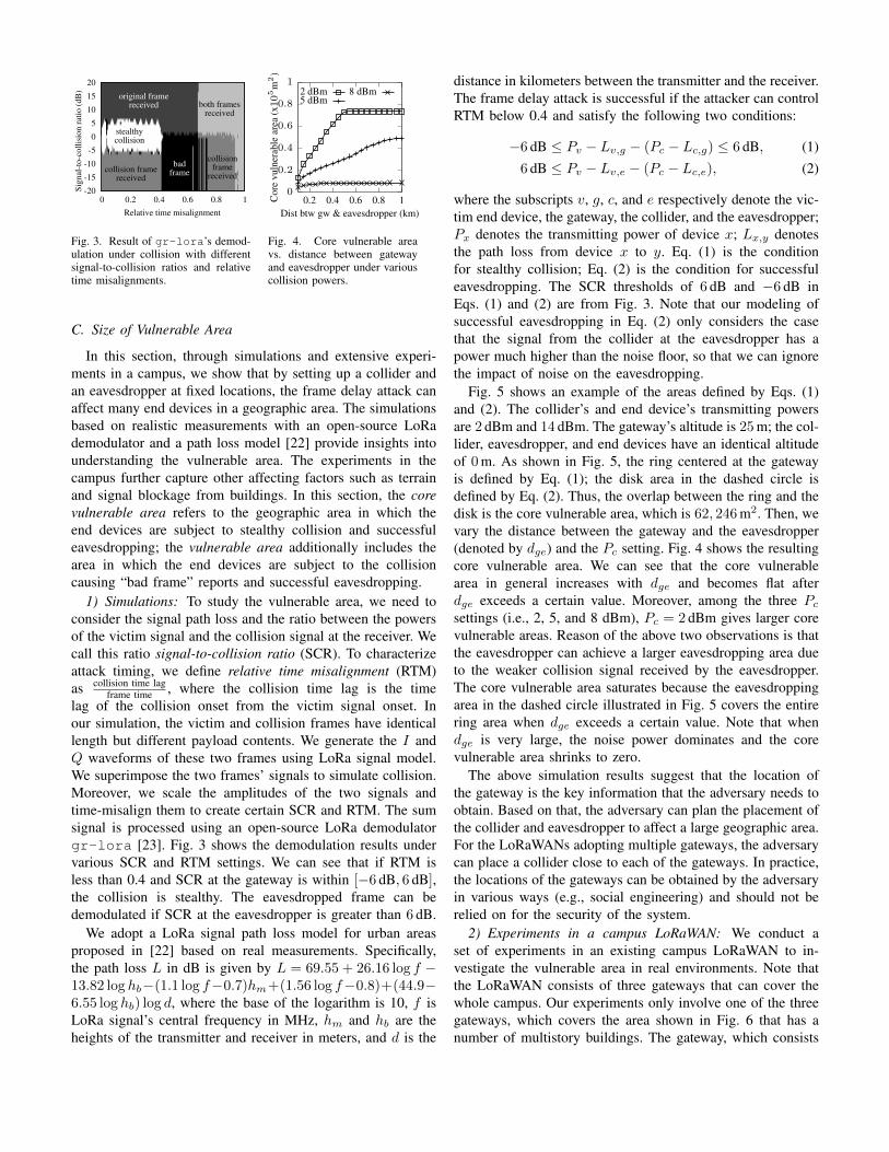
Fig. 3. Result of gr-lora’s demod-ulation under collision with differentsignal-to-collision ratios and relativetime misalignments.
0
0.2
0.4
0.6
0.8
1
0.2 0.4 0.6 0.8 1Cor
evu
lner
able
area
(x105
m2
)
Dist btw gw & eavesdropper (km)
2 dBm5 dBm
8 dBm
Fig. 4. Core vulnerable areavs. distance between gatewayand eavesdropper under variouscollision powers.
C. Size of Vulnerable Area
In this section, through simulations and extensive experi-ments in a campus, we show that by setting up a collider andan eavesdropper at fixed locations, the frame delay attack canaffect many end devices in a geographic area. The simulationsbased on realistic measurements with an open-source LoRademodulator and a path loss model [22] provide insights intounderstanding the vulnerable area. The experiments in thecampus further capture other affecting factors such as terrainand signal blockage from buildings. In this section, the corevulnerable area refers to the geographic area in which theend devices are subject to stealthy collision and successfuleavesdropping; the vulnerable area additionally includes thearea in which the end devices are subject to the collisioncausing “bad frame” reports and successful eavesdropping.
1) Simulations: To study the vulnerable area, we need toconsider the signal path loss and the ratio between the powersof the victim signal and the collision signal at the receiver. Wecall this ratio signal-to-collision ratio (SCR). To characterizeattack timing, we define relative time misalignment (RTM)as collision time lag
frame time , where the collision time lag is the timelag of the collision onset from the victim signal onset. Inour simulation, the victim and collision frames have identicallength but different payload contents. We generate the I andQ waveforms of these two frames using LoRa signal model.We superimpose the two frames’ signals to simulate collision.Moreover, we scale the amplitudes of the two signals andtime-misalign them to create certain SCR and RTM. The sumsignal is processed using an open-source LoRa demodulatorgr-lora [23]. Fig. 3 shows the demodulation results undervarious SCR and RTM settings. We can see that if RTM isless than 0.4 and SCR at the gateway is within [−6 dB, 6 dB],the collision is stealthy. The eavesdropped frame can bedemodulated if SCR at the eavesdropper is greater than 6 dB.
We adopt a LoRa signal path loss model for urban areasproposed in [22] based on real measurements. Specifically,the path loss L in dB is given by L = 69.55 + 26.16 log f −13.82 log hb−(1.1 log f−0.7)hm+(1.56 log f−0.8)+(44.9−6.55 log hb) log d, where the base of the logarithm is 10, f isLoRa signal’s central frequency in MHz, hm and hb are theheights of the transmitter and receiver in meters, and d is the
distance in kilometers between the transmitter and the receiver.The frame delay attack is successful if the attacker can controlRTM below 0.4 and satisfy the following two conditions:
−6 dB ≤ Pv − Lv,g − (Pc − Lc,g) ≤ 6 dB, (1)6 dB ≤ Pv − Lv,e − (Pc − Lc,e), (2)
where the subscripts v, g, c, and e respectively denote the vic-tim end device, the gateway, the collider, and the eavesdropper;Px denotes the transmitting power of device x; Lx,y denotesthe path loss from device x to y. Eq. (1) is the conditionfor stealthy collision; Eq. (2) is the condition for successfuleavesdropping. The SCR thresholds of 6 dB and −6 dB inEqs. (1) and (2) are from Fig. 3. Note that our modeling ofsuccessful eavesdropping in Eq. (2) only considers the casethat the signal from the collider at the eavesdropper has apower much higher than the noise floor, so that we can ignorethe impact of noise on the eavesdropping.
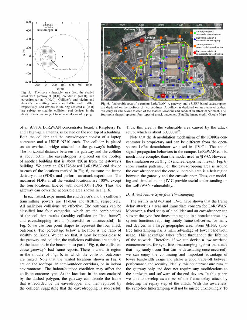
Fig. 5 shows an example of the areas defined by Eqs. (1)and (2). The collider’s and end device’s transmitting powersare 2 dBm and 14 dBm. The gateway’s altitude is 25 m; the col-lider, eavesdropper, and end devices have an identical altitudeof 0 m. As shown in Fig. 5, the ring centered at the gatewayis defined by Eq. (1); the disk area in the dashed circle isdefined by Eq. (2). Thus, the overlap between the ring and thedisk is the core vulnerable area, which is 62, 246 m2. Then, wevary the distance between the gateway and the eavesdropper(denoted by dge) and the Pc setting. Fig. 4 shows the resultingcore vulnerable area. We can see that the core vulnerablearea in general increases with dge and becomes flat afterdge exceeds a certain value. Moreover, among the three Pcsettings (i.e., 2, 5, and 8 dBm), Pc = 2 dBm gives larger corevulnerable areas. Reason of the above two observations is thatthe eavesdropper can achieve a larger eavesdropping area dueto the weaker collision signal received by the eavesdropper.The core vulnerable area saturates because the eavesdroppingarea in the dashed circle illustrated in Fig. 5 covers the entirering area when dge exceeds a certain value. Note that whendge is very large, the noise power dominates and the corevulnerable area shrinks to zero.
The above simulation results suggest that the location ofthe gateway is the key information that the adversary needs toobtain. Based on that, the adversary can plan the placement ofthe collider and eavesdropper to affect a large geographic area.For the LoRaWANs adopting multiple gateways, the adversarycan place a collider close to each of the gateways. In practice,the locations of the gateways can be obtained by the adversaryin various ways (e.g., social engineering) and should not berelied on for the security of the system.
2) Experiments in a campus LoRaWAN: We conduct aset of experiments in an existing campus LoRaWAN to in-vestigate the vulnerable area in real environments. Note thatthe LoRaWAN consists of three gateways that can cover thewhole campus. Our experiments only involve one of the threegateways, which covers the area shown in Fig. 6 that has anumber of multistory buildings. The gateway, which consists
-600
-400
-200
0
200
400
600
800
-200 0 200 400 600 800 1000
y(m
)
x (m)
Core vulnerable area
gatewaycollider
eavesdropper
Fig. 5. The core vulnerable area (i.e., the shadedarea) with gateway at (0, 0), collider at (50, 0), andeavesdropper at (400, 0). Collider’s and victim enddevice’s transmitting powers are 2 dBm and 14 dBm,respectively. End devices in the ring centered at (0, 0)are subject to stealthy collision; end devices in thedashed circle are subject to successful eavesdropping.
0,0
Gateway
Eavesdropper
Collider
replayer
100m 200m 300m 400m 500m 600m
100m
200m
300m
360m
FDR: 95%
FDR: 95%
FDR: 45% FDR: 95%
90%
100%100%
90%70%
100%100%
100%
100%
20%
90%
90%100%
100%
100%
100% 100%
100%
100%
100%
Stealthy collision &successful eavesdropping
Stealthy collision &unsuccessful eavesdropping
Bad frame collision &successful eavesdropping
Bad frame collision &unsuccessful eavesdropping Vulnerable
area
Fig. 6. Vulnerable area of a campus LoRaWAN. A gateway and a USRP-based eavesdropperare deployed on the rooftops of two buildings. A collider is deployed on an overhead bridge.We carry an end device to each of the marked locations and conduct an attack experiment. Thefour point shapes represent four types of attack outcomes. (Satellite image credit: Google Map)
of an iC880a LoRaWAN concentrator board, a Raspberry Pi,and a high-gain antenna, is located on the rooftop of a building.Both the collider and the eavesdropper consist of a laptopcomputer and a USRP N210 each. The collider is placedon an overhead bridge attached to the gateway’s building.The horizontal distance between the gateway and the collideris about 50 m. The eavesdropper is placed on the rooftopof another building that is about 320 m from the gateway’sbuilding. We carry an SX1276-based LoRaWAN end deviceto each of the locations marked in Fig. 6, measure the framedelivery ratio (FDR), and perform an attack experiment. Themeasured FDRs at all the visited locations are 100%, exceptthe four locations labeled with non-100% FDRs. Thus, thegateway can cover the accessible area shown in Fig. 6.
In each attack experiment, the end device’s and the collider’stransmitting powers are 14 dBm and 8 dBm, respectively.All malicious collisions are effective. The outcomes can beclassified into four categories, which are the combinationsof the collision results (stealthy collision or “bad frame”)and eavesdropping results (successful or unsuccessful). InFig. 6, we use four point shapes to represent the four attackoutcomes. The percentage below a location is the ratio ofstealthy collisions. We can see that, at most locations close tothe gateway and collider, the malicious collisions are stealthy.At the locations in the bottom most part of Fig. 6, the collisionscause gateway’s bad frame reports. There is a transit regionin the middle of Fig. 6, in which the collision outcomesare mixed. Note that the visited locations shown in Fig. 6are on the rooftops, in semi-outdoor corridors, or in indoorenvironments. The indoor/outdoor condition may affect thecollision outcome type. At the locations in the area enclosedby the dashed polygon, the gateway can decode the framethat is recorded by the eavesdropper and then replayed bythe collider, suggesting that the eavesdropping is successful.
Thus, this area is the vulnerable area caused by the attacksetup, which is about 50, 000 m2.
Note that the demodulation mechanism of the iC880a con-centrator is proprietary and can be different from the open-source LoRa demodulator we used in §IV-C1. The actualsignal propagation behaviors in the campus LoRaWAN can bemuch more complex than the model used in §IV-C. However,the simulation result (Fig. 5) and real experiment result (Fig. 6)show similar patterns, i.e., the eavesdropping area is aroundthe eavesdropper and the core vulnerable area is a belt regionbetween the gateway and the eavesdropper. Thus, our model-ing and simulations in §IV-C provide useful understanding onthe LoRaWAN vulnerability.
D. Attack-Aware Sync-free Timestamping
The results in §IV-B and §IV-C have shown that the framedelay attack is a real and immediate concern for LoRaWAN.Moreover, a fixed setup of a collider and an eavesdropper cansubvert the sync-free timestamping and in a broader sense, anysystem functions requiring timely frame deliveries, for manyend devices in a large geographic area. From §III-B, sync-free timestamping has a main advantage of lower bandwidthusage. This advantage takes effect throughout the lifetimeof the network. Therefore, if we can devise a low-overheadcountermeasure for sync-free timestamping against the attackthat may rarely occur (but can be devastating once occurred),we can enjoy the continuing and important advantage oflower bandwidth usage and strike a good trade-off betweenperformance and security. Ideally, this countermeasure runs atthe gateway only and does not require any modifications tothe hardware and software of the end devices. In this paper,we aim to develop awareness of the frame delay attack bydetecting the replay step of the attack. With this awareness,the sync-free timestamping will not be misled unknowingly. To
iC880a868MHzantenna
RTL-SDRdongle
Raspberry Pi
Bridgeboard
5dBi fiberglass868MHz antenna
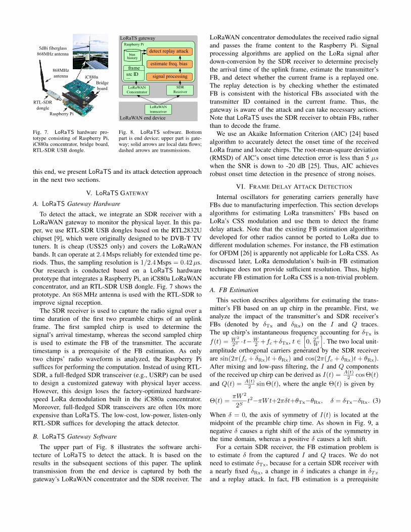
Fig. 7. LoRaTS hardware pro-totype consisting of Raspberry Pi,iC880a concentrator, bridge board,RTL-SDR USB dongle.
LoRaWANtransceiver
Raspberry Pi
signal processingframe
src ID...
estimate freq. bias
detect replay attack history
bias
LoRaTS gateway
LoRaWAN end device
LoRaWANConcentrator
SDRReceiver
Fig. 8. LoRaTS software. Bottompart is end device; upper part is gate-way; solid arrows are local data flows;dashed arrows are transmissions.
this end, we present LoRaTS and its attack detection approachin the next two sections.
V. LoRaTS GATEWAY
A. LoRaTS Gateway Hardware
To detect the attack, we integrate an SDR receiver with aLoRaWAN gateway to monitor the physical layer. In this pa-per, we use RTL-SDR USB dongles based on the RTL2832Uchipset [9], which were originally designed to be DVB-T TVtuners. It is cheap (US$25 only) and covers the LoRaWANbands. It can operate at 2.4 Msps reliably for extended time pe-riods. Thus, the sampling resolution is 1/2.4 Msps = 0.42µs.Our research is conducted based on a LoRaTS hardwareprototype that integrates a Raspberry Pi, an iC880a LoRaWANconcentrator, and an RTL-SDR USB dongle. Fig. 7 shows theprototype. An 868 MHz antenna is used with the RTL-SDR toimprove signal reception.
The SDR receiver is used to capture the radio signal over atime duration of the first two preamble chirps of an uplinkframe. The first sampled chirp is used to determine thesignal’s arrival timestamp, whereas the second sampled chirpis used to estimate the FB of the transmitter. The accuratetimestamp is a prerequisite of the FB estimation. As onlytwo chirps’ radio waveform is analyzed, the Raspberry Pisuffices for performing the computation. Instead of using RTL-SDR, a full-fledged SDR transceiver (e.g., USRP) can be usedto design a customized gateway with physical layer access.However, this design loses the factory-optimized hardware-speed LoRa demodulation built in the iC880a concentrator.Moreover, full-fledged SDR transceivers are often 10x moreexpensive than LoRaTS. The low-cost, low-power, listen-onlyRTL-SDR suffices for developing the attack detector.
B. LoRaTS Gateway Software
The upper part of Fig. 8 illustrates the software archi-tecture of LoRaTS to detect the attack. It is based on theresults in the subsequent sections of this paper. The uplinktransmission from the end device is captured by both thegateway’s LoRaWAN concentrator and the SDR receiver. The
LoRaWAN concentrator demodulates the received radio signaland passes the frame content to the Raspberry Pi. Signalprocessing algorithms are applied on the LoRa signal afterdown-conversion by the SDR receiver to determine preciselythe arrival time of the uplink frame, estimate the transmitter’sFB, and detect whether the current frame is a replayed one.The replay detection is by checking whether the estimatedFB is consistent with the historical FBs associated with thetransmitter ID contained in the current frame. Thus, thegateway is aware of the attack and can take necessary actions.Note that LoRaTS uses the SDR receiver to obtain FBs, ratherthan to decode the frame.
We use an Akaike Information Criterion (AIC) [24] basedalgorithm to accurately detect the onset time of the receivedLoRa frame and locate chirps. The root-mean-square deviation(RMSD) of AIC’s onset time detection error is less than 5 µswhen the SNR is down to -20 dB [25]. Thus, AIC achievesrobust onset time detection in the presence of strong noises.
VI. FRAME DELAY ATTACK DETECTION
Internal oscillators for generating carriers generally haveFBs due to manufacturing imperfection. This section developsalgorithms for estimating LoRa transmitters’ FBs based onLoRa’s CSS modulation and use them to detect the framedelay attack. Note that the existing FB estimation algorithmsdeveloped for other radios cannot be ported to LoRa due todifferent modulation schemes. For instance, the FB estimationfor OFDM [26] is apparently not applicable for LoRa CSS. Asdiscussed later, LoRa demodulation’s built-in FB estimationtechnique does not provide sufficient resolution. Thus, highlyaccurate FB estimation for LoRa CSS is a non-trivial problem.
A. FB Estimation
This section describes algorithms for estimating the trans-mitter’s FB based on an up chirp in the preamble. First, weanalyze the impact of the transmitter’s and SDR receiver’sFBs (denoted by δTx and δRx) on the I and Q traces.The up chirp’s instantaneous frequency accounting for δTx isf(t) = W 2
2S·t−W
2 +fc+δTx, t ∈[0, 2
S
W
]. The two local unit-
amplitude orthogonal carriers generated by the SDR receiverare sin(2π(fc + δRx)t+ θRx) and cos(2π(fc + δRx)t+ θRx).After mixing and low-pass filtering, the I and Q componentsof the received up chirp can be derived as I(t) = A(t)
2 cos Θ(t)
and Q(t) = A(t)2 sin Θ(t), where the angle Θ(t) is given by
Θ(t) =πW 2
2St2−πWt+2πδt+θTx−θRx, δ = δTx−δRx. (3)
When δ = 0, the axis of symmetry of I(t) is located at themidpoint of the preamble chirp time. As shown in Fig. 9, anegative δ causes a right shift of the axis of the symmetry inthe time domain, whereas a positive δ causes a left shift.
For a certain SDR receiver, the FB estimation problem isto estimate δ from the captured I and Q traces. We do notneed to estimate δTx, because for a certain SDR receiver witha nearly fixed δRx, a change in δ indicates a change in δTxand a replay attack. In fact, FB estimation is a prerequisite

−1
0
1
0 0.2 0.4 0.6 0.8 1
I(t)
Time t (ms)
Fig. 9. Actual I data of a preamblechirp. The time shift of the axis ofsymmetry represented by the dashedline is caused by FB.
-600-500-400-300-200-100
0
0 0.5 1.0Time (ms)
Θ(t)Θ(t)- πW2
2St2+πWt
Fig. 10. FB estimation us-ing linear regression. The twocurves are generated from ac-tual I and Q data.
of LoRa demodulation. Now, we discuss the incompetenceof the LoRa demodulators’ built-in FB estimation techniquefor attack detection. LoRa’s CSS scheme evenly divides thewhole channel bandwidth of W Hz into 2S bins, where S is thespreading factor. The starting frequency of a bin correspondsto a symbol state. Since the preamble chirp linearly swapsthe channel bandwidth, its starting frequency can be viewedas the FB. LoRa demodulation firstly applies dechirping andthen FFT to identify the preamble’s and any data chirp’sstarting frequency bin indexes. The difference between thetwo indexes is the symbol state. As FFT achieves a resolutionof 1
x Hz using x seconds of data, the Fourier transform of achirp with length of 2S
W seconds has a frequency resolution ofW2S
Hz. This is also the resolution of the built-in FB estimation.Thus, for low spreading factor settings, the resolution maybe poor. For instance, when S = 7 and W = 125 kHz, theresolution is 976.56 Hz. However, as we will show in §VI-B,this near-1 kHz resolution is insufficient to detect attacks thatintroduce sub-1 kHz FBs. The colliding frame disentanglementapproach Choir [10] also uses the dechirping-FFT pipeline toanalyze FB. Thus, it is subject to the insufficient resolution.To achieve higher resolutions, this section presents two time-domain approaches designed based on Eq. (3).
1) Linear regression approach: Eq. (3) can be rewritten asΘ(t)−πW
2
2St2+πWt = 2πδt+θ, which is a linear function of t
with 2πδ as the slope. Thus, the slope can be estimated by lin-ear regression based on the data pairs (t,Θ(t)−πW
2
2St2+πWt),
where t ∈[0, 2
S
W
], Θ(t) = atan2(Q(t), I(t)) + 2kπ, and
k ∈ Z rectifies the multi-valued inverse tangent functionatan2(·, ·) ∈ (−π, π) to an unlimited value domain. Thedetails of the rectification are omitted here due to spacelimitation and can be found in [25]. Note that the I(t) and Q(t)are the I and Q data traces captured by the SDR receiver for acomplete preamble chirp. The preamble onset time detected byAIC is used to segment the I and Q traces to chirps. Fig. 10shows the Θ(t) computed from real I and Q traces of thesecond chirp of a preamble emitted by an SX1276-based enddevice and captured by LoRaTS’s SDR receiver. It also showsΘ(t)−πW
2
2St2+πWt, which is indeed a linear function of time.
As the linear regression approach has a closed-form formulato compute δ, it has a complexity of O(1).
2) Least squares approach: The LoRa signals can bevery weak after long-distance propagation or barrier pen-etration. The LoRa’s demodulation is designed to address
-2
2
6
10
10 15 20 25 30 35 40
FBer
ror(
kHz)
SNR (dB)
(a) Linear regression
-0.15-0.1
-0.050
0.050.1
0.15
-18 -13 -8 -3 2
FBer
ror(
kHz)
SNR (dB)
(b) Least squares
Fig. 11. FB estimation errors vs. SNR.
low SNRs. For SX1276, the minimum SNRs required forreliable demodulation with spreading factors of 7 to 12are −7.5 dB to −20 dB [27]. We aim at extracting FBat such low SNRs. We solve a least squares problem:arg minθTx−θRx∈[0,2π),δ
∑t∈[0,2S/W ] (Q(t)−A sin Θ(t))
2+
(I(t)−A cos Θ(t))2, where Q(t) and I(t) are the received
Q and I traces; Θ(t) is given by Eq. (3); A sin Θ(t) andA cos Θ(t) are the noiseless Q and I templates. The aboveformulation requires that the Q and I templates have an iden-tical and constant amplitude A. As the second preamble chirpcan meet this requirement, we use it for FB estimation. The Acan be estimated as the square root of the difference betweenthe average powers of the LoRa signal and the pure noise.We use a scipy implementation of the differential evolutionalgorithm to solve the least squares problem. Raspberry Piuses 0.69 seconds to solve it.
3) Performance comparison: We compare the FB estima-tion accuracy of the linear regression and the least squaresapproaches. Fig. 11 shows the results. For each SNR setting,20 LoRa I and Q traces with random FBs are generatedusing the signal model in Eq. (3). We also generate 20 noisestraces; the magnitude of the noise is controlled to achievethe specified SNR. In Fig. 11, each error bar showing the20%- and 80%-percentiles is from the 20 FB estimationresults performed on the sum signals of the generated idealLoRa signals and noise. From Fig. 11(a), the linear regressionapproach can achieve low FB estimation errors when the SNRis very high (e.g., 40 dB). However, it performs poorly forlow SNRs. This is caused by the susceptibility of the inversetangent rectification to noises. Specifically, as the inversetangent rectification is based on a heuristic to detect atan2’ssudden transitions between −π and π, large noises leads tofalse positive detection of the transitions. Differently, the leastsquares approach maintains the FB estimation error within120 Hz (i.e., 0.14 ppm), when the SNR is down to −18 dB.Thus, the rest of this paper adopts the noise-resilient leastsquares approach, though it is more compute-intensive.
4) FB measurements for 16 end devices: We use an RTL-SDR to estimate the FBs of 16 SX1276-based end devices.In each test for an end device, the distance between the enddevice and the RTL-SDR is about 5 m. The error bars labeled“original” in Fig. 12 show the results. We can see that theFBs for a certain node are stable and the nodes generallyhave different FBs. The absolute FBs are from 17 kHz to25 kHz, which are about 20 ppm to 29 ppm of the nominal
-25-24-23-22-21-20-19-18
0 1 2 3 4 5 6 7 8 9 10 11 12 13 14 15
Freq
uenc
ybi
asδ
(kH
z)
Source node ID
originalreplayed
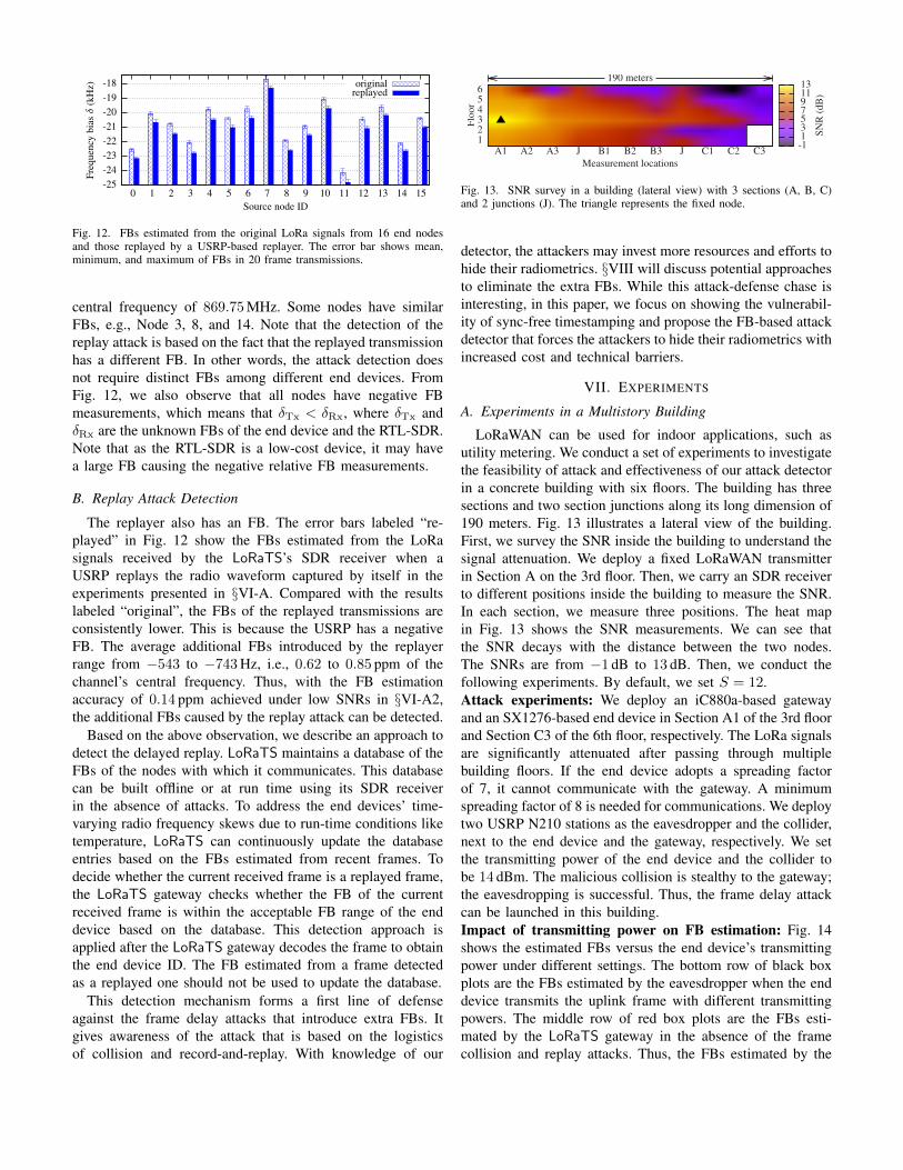
Fig. 12. FBs estimated from the original LoRa signals from 16 end nodesand those replayed by a USRP-based replayer. The error bar shows mean,minimum, and maximum of FBs in 20 frame transmissions.
central frequency of 869.75 MHz. Some nodes have similarFBs, e.g., Node 3, 8, and 14. Note that the detection of thereplay attack is based on the fact that the replayed transmissionhas a different FB. In other words, the attack detection doesnot require distinct FBs among different end devices. FromFig. 12, we also observe that all nodes have negative FBmeasurements, which means that δTx < δRx, where δTx andδRx are the unknown FBs of the end device and the RTL-SDR.Note that as the RTL-SDR is a low-cost device, it may havea large FB causing the negative relative FB measurements.
B. Replay Attack Detection
The replayer also has an FB. The error bars labeled “re-played” in Fig. 12 show the FBs estimated from the LoRasignals received by the LoRaTS’s SDR receiver when aUSRP replays the radio waveform captured by itself in theexperiments presented in §VI-A. Compared with the resultslabeled “original”, the FBs of the replayed transmissions areconsistently lower. This is because the USRP has a negativeFB. The average additional FBs introduced by the replayerrange from −543 to −743 Hz, i.e., 0.62 to 0.85 ppm of thechannel’s central frequency. Thus, with the FB estimationaccuracy of 0.14 ppm achieved under low SNRs in §VI-A2,the additional FBs caused by the replay attack can be detected.
Based on the above observation, we describe an approach todetect the delayed replay. LoRaTS maintains a database of theFBs of the nodes with which it communicates. This databasecan be built offline or at run time using its SDR receiverin the absence of attacks. To address the end devices’ time-varying radio frequency skews due to run-time conditions liketemperature, LoRaTS can continuously update the databaseentries based on the FBs estimated from recent frames. Todecide whether the current received frame is a replayed frame,the LoRaTS gateway checks whether the FB of the currentreceived frame is within the acceptable FB range of the enddevice based on the database. This detection approach isapplied after the LoRaTS gateway decodes the frame to obtainthe end device ID. The FB estimated from a frame detectedas a replayed one should not be used to update the database.
This detection mechanism forms a first line of defenseagainst the frame delay attacks that introduce extra FBs. Itgives awareness of the attack that is based on the logisticsof collision and record-and-replay. With knowledge of our
Floo
r
Measurement locationsA1 A2 A3 J B1 B2 B3 J C1 C2 C3
123456
190 meters
-1135791113
SNR
(dB
)
Fig. 13. SNR survey in a building (lateral view) with 3 sections (A, B, C)and 2 junctions (J). The triangle represents the fixed node.
detector, the attackers may invest more resources and efforts tohide their radiometrics. §VIII will discuss potential approachesto eliminate the extra FBs. While this attack-defense chase isinteresting, in this paper, we focus on showing the vulnerabil-ity of sync-free timestamping and propose the FB-based attackdetector that forces the attackers to hide their radiometrics withincreased cost and technical barriers.
VII. EXPERIMENTS
A. Experiments in a Multistory Building
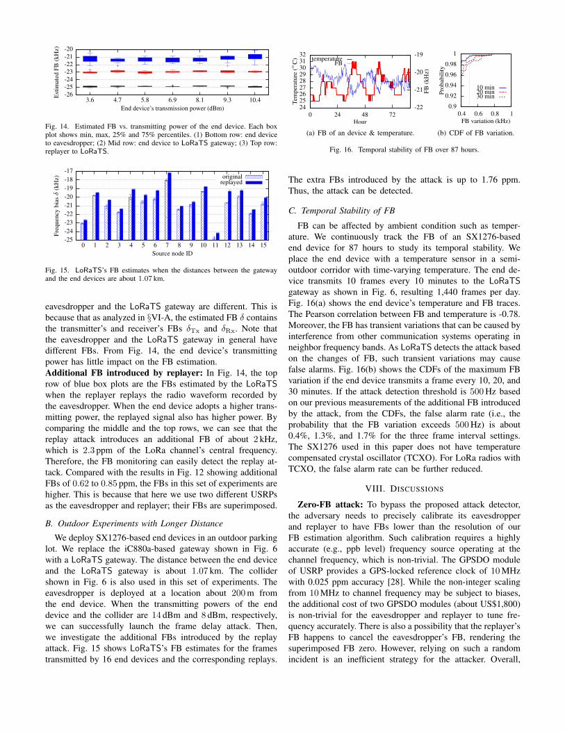
LoRaWAN can be used for indoor applications, such asutility metering. We conduct a set of experiments to investigatethe feasibility of attack and effectiveness of our attack detectorin a concrete building with six floors. The building has threesections and two section junctions along its long dimension of190 meters. Fig. 13 illustrates a lateral view of the building.First, we survey the SNR inside the building to understand thesignal attenuation. We deploy a fixed LoRaWAN transmitterin Section A on the 3rd floor. Then, we carry an SDR receiverto different positions inside the building to measure the SNR.In each section, we measure three positions. The heat mapin Fig. 13 shows the SNR measurements. We can see thatthe SNR decays with the distance between the two nodes.The SNRs are from −1 dB to 13 dB. Then, we conduct thefollowing experiments. By default, we set S = 12.Attack experiments: We deploy an iC880a-based gatewayand an SX1276-based end device in Section A1 of the 3rd floorand Section C3 of the 6th floor, respectively. The LoRa signalsare significantly attenuated after passing through multiplebuilding floors. If the end device adopts a spreading factorof 7, it cannot communicate with the gateway. A minimumspreading factor of 8 is needed for communications. We deploytwo USRP N210 stations as the eavesdropper and the collider,next to the end device and the gateway, respectively. We setthe transmitting power of the end device and the collider tobe 14 dBm. The malicious collision is stealthy to the gateway;the eavesdropping is successful. Thus, the frame delay attackcan be launched in this building.Impact of transmitting power on FB estimation: Fig. 14shows the estimated FBs versus the end device’s transmittingpower under different settings. The bottom row of black boxplots are the FBs estimated by the eavesdropper when the enddevice transmits the uplink frame with different transmittingpowers. The middle row of red box plots are the FBs esti-mated by the LoRaTS gateway in the absence of the framecollision and replay attacks. Thus, the FBs estimated by the
-26-25-24-23-22-21-20
3.6 4.7 5.8 6.9 8.1 9.3 10.4Est
imat
edFB
(kH
z)
End device’s transmission power (dBm)
Fig. 14. Estimated FB vs. transmitting power of the end device. Each boxplot shows min, max, 25% and 75% percentiles. (1) Bottom row: end deviceto eavesdropper; (2) Mid row: end device to LoRaTS gateway; (3) Top row:replayer to LoRaTS.
-25-24-23-22-21-20-19-18-17
0 1 2 3 4 5 6 7 8 9 10 11 12 13 14 15
Freq
uenc
ybi
asδ
(kH
z)
Source node ID
originalreplayed
Fig. 15. LoRaTS’s FB estimates when the distances between the gatewayand the end devices are about 1.07 km.
eavesdropper and the LoRaTS gateway are different. This isbecause that as analyzed in §VI-A, the estimated FB δ containsthe transmitter’s and receiver’s FBs δTx and δRx. Note thatthe eavesdropper and the LoRaTS gateway in general havedifferent FBs. From Fig. 14, the end device’s transmittingpower has little impact on the FB estimation.Additional FB introduced by replayer: In Fig. 14, the toprow of blue box plots are the FBs estimated by the LoRaTSwhen the replayer replays the radio waveform recorded bythe eavesdropper. When the end device adopts a higher trans-mitting power, the replayed signal also has higher power. Bycomparing the middle and the top rows, we can see that thereplay attack introduces an additional FB of about 2 kHz,which is 2.3 ppm of the LoRa channel’s central frequency.Therefore, the FB monitoring can easily detect the replay at-tack. Compared with the results in Fig. 12 showing additionalFBs of 0.62 to 0.85 ppm, the FBs in this set of experiments arehigher. This is because that here we use two different USRPsas the eavesdropper and replayer; their FBs are superimposed.
B. Outdoor Experiments with Longer Distance
We deploy SX1276-based end devices in an outdoor parkinglot. We replace the iC880a-based gateway shown in Fig. 6with a LoRaTS gateway. The distance between the end deviceand the LoRaTS gateway is about 1.07 km. The collidershown in Fig. 6 is also used in this set of experiments. Theeavesdropper is deployed at a location about 200 m fromthe end device. When the transmitting powers of the enddevice and the collider are 14 dBm and 8 dBm, respectively,we can successfully launch the frame delay attack. Then,we investigate the additional FBs introduced by the replayattack. Fig. 15 shows LoRaTS’s FB estimates for the framestransmitted by 16 end devices and the corresponding replays.
242526272829303132
0 24 48 72-22
-21
-20
-19
Tem
pera
ture
(◦C
)
FB(k
Hz)
Hour
temperatureFB
(a) FB of an device & temperature.
0.9
0.92
0.94
0.96
0.98
1
0.4 0.6 0.8 1
Prob
abili
ty
FB variation (kHz)
10 min20 min30 min
(b) CDF of FB variation.
Fig. 16. Temporal stability of FB over 87 hours.
The extra FBs introduced by the attack is up to 1.76 ppm.Thus, the attack can be detected.
C. Temporal Stability of FB
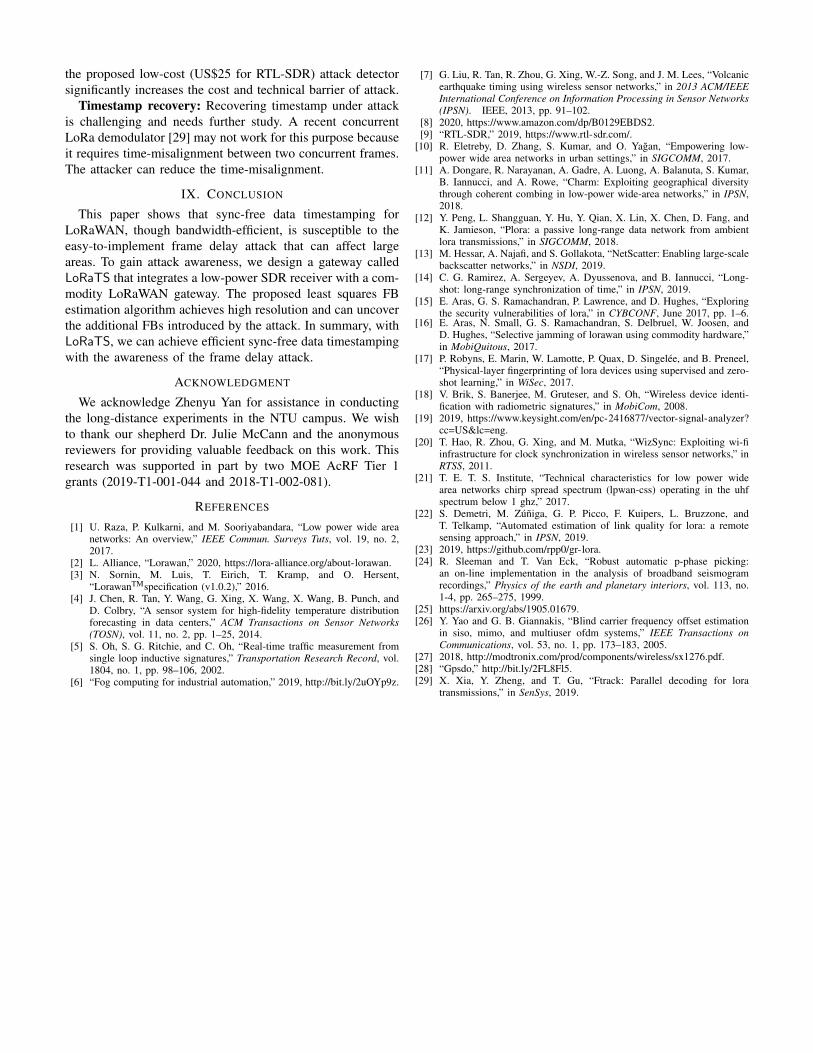
FB can be affected by ambient condition such as temper-ature. We continuously track the FB of an SX1276-basedend device for 87 hours to study its temporal stability. Weplace the end device with a temperature sensor in a semi-outdoor corridor with time-varying temperature. The end de-vice transmits 10 frames every 10 minutes to the LoRaTSgateway as shown in Fig. 6, resulting 1,440 frames per day.Fig. 16(a) shows the end device’s temperature and FB traces.The Pearson correlation between FB and temperature is -0.78.Moreover, the FB has transient variations that can be caused byinterference from other communication systems operating inneighbor frequency bands. As LoRaTS detects the attack basedon the changes of FB, such transient variations may causefalse alarms. Fig. 16(b) shows the CDFs of the maximum FBvariation if the end device transmits a frame every 10, 20, and30 minutes. If the attack detection threshold is 500 Hz basedon our previous measurements of the additional FB introducedby the attack, from the CDFs, the false alarm rate (i.e., theprobability that the FB variation exceeds 500 Hz) is about0.4%, 1.3%, and 1.7% for the three frame interval settings.The SX1276 used in this paper does not have temperaturecompensated crystal oscillator (TCXO). For LoRa radios withTCXO, the false alarm rate can be further reduced.
VIII. DISCUSSIONS
Zero-FB attack: To bypass the proposed attack detector,the adversary needs to precisely calibrate its eavesdropperand replayer to have FBs lower than the resolution of ourFB estimation algorithm. Such calibration requires a highlyaccurate (e.g., ppb level) frequency source operating at thechannel frequency, which is non-trivial. The GPSDO moduleof USRP provides a GPS-locked reference clock of 10 MHzwith 0.025 ppm accuracy [28]. While the non-integer scalingfrom 10 MHz to channel frequency may be subject to biases,the additional cost of two GPSDO modules (about US$1,800)is non-trivial for the eavesdropper and replayer to tune fre-quency accurately. There is also a possibility that the replayer’sFB happens to cancel the eavesdropper’s FB, rendering thesuperimposed FB zero. However, relying on such a randomincident is an inefficient strategy for the attacker. Overall,
the proposed low-cost (US$25 for RTL-SDR) attack detectorsignificantly increases the cost and technical barrier of attack.
Timestamp recovery: Recovering timestamp under attackis challenging and needs further study. A recent concurrentLoRa demodulator [29] may not work for this purpose becauseit requires time-misalignment between two concurrent frames.The attacker can reduce the time-misalignment.
IX. CONCLUSION
This paper shows that sync-free data timestamping forLoRaWAN, though bandwidth-efficient, is susceptible to theeasy-to-implement frame delay attack that can affect largeareas. To gain attack awareness, we design a gateway calledLoRaTS that integrates a low-power SDR receiver with a com-modity LoRaWAN gateway. The proposed least squares FBestimation algorithm achieves high resolution and can uncoverthe additional FBs introduced by the attack. In summary, withLoRaTS, we can achieve efficient sync-free data timestampingwith the awareness of the frame delay attack.
ACKNOWLEDGMENT
We acknowledge Zhenyu Yan for assistance in conductingthe long-distance experiments in the NTU campus. We wishto thank our shepherd Dr. Julie McCann and the anonymousreviewers for providing valuable feedback on this work. Thisresearch was supported in part by two MOE AcRF Tier 1grants (2019-T1-001-044 and 2018-T1-002-081).
REFERENCES
[1] U. Raza, P. Kulkarni, and M. Sooriyabandara, “Low power wide areanetworks: An overview,” IEEE Commun. Surveys Tuts, vol. 19, no. 2,2017.
[2] L. Alliance, “Lorawan,” 2020, https://lora-alliance.org/about-lorawan.[3] N. Sornin, M. Luis, T. Eirich, T. Kramp, and O. Hersent,
“LorawanTMspecification (v1.0.2),” 2016.[4] J. Chen, R. Tan, Y. Wang, G. Xing, X. Wang, X. Wang, B. Punch, and
D. Colbry, “A sensor system for high-fidelity temperature distributionforecasting in data centers,” ACM Transactions on Sensor Networks(TOSN), vol. 11, no. 2, pp. 1–25, 2014.
[5] S. Oh, S. G. Ritchie, and C. Oh, “Real-time traffic measurement fromsingle loop inductive signatures,” Transportation Research Record, vol.1804, no. 1, pp. 98–106, 2002.
[6] “Fog computing for industrial automation,” 2019, http://bit.ly/2uOYp9z.
[7] G. Liu, R. Tan, R. Zhou, G. Xing, W.-Z. Song, and J. M. Lees, “Volcanicearthquake timing using wireless sensor networks,” in 2013 ACM/IEEEInternational Conference on Information Processing in Sensor Networks(IPSN). IEEE, 2013, pp. 91–102.
[8] 2020, https://www.amazon.com/dp/B0129EBDS2.[9] “RTL-SDR,” 2019, https://www.rtl-sdr.com/.
[10] R. Eletreby, D. Zhang, S. Kumar, and O. Yagan, “Empowering low-power wide area networks in urban settings,” in SIGCOMM, 2017.
[11] A. Dongare, R. Narayanan, A. Gadre, A. Luong, A. Balanuta, S. Kumar,B. Iannucci, and A. Rowe, “Charm: Exploiting geographical diversitythrough coherent combing in low-power wide-area networks,” in IPSN,2018.
[12] Y. Peng, L. Shangguan, Y. Hu, Y. Qian, X. Lin, X. Chen, D. Fang, andK. Jamieson, “Plora: a passive long-range data network from ambientlora transmissions,” in SIGCOMM, 2018.
[13] M. Hessar, A. Najafi, and S. Gollakota, “NetScatter: Enabling large-scalebackscatter networks,” in NSDI, 2019.
[14] C. G. Ramirez, A. Sergeyev, A. Dyussenova, and B. Iannucci, “Long-shot: long-range synchronization of time,” in IPSN, 2019.
[15] E. Aras, G. S. Ramachandran, P. Lawrence, and D. Hughes, “Exploringthe security vulnerabilities of lora,” in CYBCONF, June 2017, pp. 1–6.
[16] E. Aras, N. Small, G. S. Ramachandran, S. Delbruel, W. Joosen, andD. Hughes, “Selective jamming of lorawan using commodity hardware,”in MobiQuitous, 2017.
[17] P. Robyns, E. Marin, W. Lamotte, P. Quax, D. Singelee, and B. Preneel,“Physical-layer fingerprinting of lora devices using supervised and zero-shot learning,” in WiSec, 2017.
[18] V. Brik, S. Banerjee, M. Gruteser, and S. Oh, “Wireless device identi-fication with radiometric signatures,” in MobiCom, 2008.
[19] 2019, https://www.keysight.com/en/pc-2416877/vector-signal-analyzer?cc=US&lc=eng.
[20] T. Hao, R. Zhou, G. Xing, and M. Mutka, “WizSync: Exploiting wi-fiinfrastructure for clock synchronization in wireless sensor networks,” inRTSS, 2011.
[21] T. E. T. S. Institute, “Technical characteristics for low power widearea networks chirp spread spectrum (lpwan-css) operating in the uhfspectrum below 1 ghz,” 2017.
[22] S. Demetri, M. Zuniga, G. P. Picco, F. Kuipers, L. Bruzzone, andT. Telkamp, “Automated estimation of link quality for lora: a remotesensing approach,” in IPSN, 2019.
[23] 2019, https://github.com/rpp0/gr-lora.[24] R. Sleeman and T. Van Eck, “Robust automatic p-phase picking:
an on-line implementation in the analysis of broadband seismogramrecordings,” Physics of the earth and planetary interiors, vol. 113, no.1-4, pp. 265–275, 1999.
[25] https://arxiv.org/abs/1905.01679.[26] Y. Yao and G. B. Giannakis, “Blind carrier frequency offset estimation
in siso, mimo, and multiuser ofdm systems,” IEEE Transactions onCommunications, vol. 53, no. 1, pp. 173–183, 2005.
[27] 2018, http://modtronix.com/prod/components/wireless/sx1276.pdf.[28] “Gpsdo,” http://bit.ly/2FL8Fl5.[29] X. Xia, Y. Zheng, and T. Gu, “Ftrack: Parallel decoding for lora
transmissions,” in SenSys, 2019.