au tograph transkit gto engine kit b r autograph
TRANSCRIPT
TRANSKIT 250 GTO 1/12 ENGINE KIT BASIS REVELL Au
PART 2: ENGINE KIT PLEASE VISIT US IN THE INTERNET: WWW.AUTOGRAPHMODEL.COM PAGE - 1 -
tograph
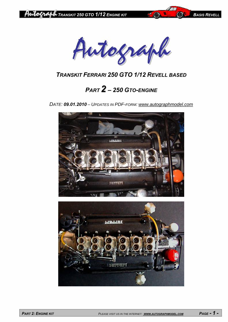
AAuuttooggrraapphh TRANSKIT FERRARI 250 GTO 1/12 REVELL BASED
PART 22 – 250 GTO-ENGINE
DATE: 09.01.2010 – UPDATES IN PDF-FORM: www.autographmodel.com

TRANSKIT 250 GTO 1/12 ENGINE KIT BASIS REVELL Au
PART 2: ENGINE KIT PLEASE VISIT US IN THE INTERNET: WWW.AUTOGRAPHMODEL.COM PAGE - 2 -
tograph
PART 22 CONTENT:
PART 2 CHAPTER 1: TOOLS AND PARTS Page Content ..................................................................................................................................................2 Tools ......................................................................................................................................................3
Resine-cast parts RS.............................................................................................................................4 White metal-cast parts WM ...................................................................................................................5 Solder and flux H ...................................................................................................................................6 Other parts T..........................................................................................................................................7 Brass sleeves L .....................................................................................................................................7 Nuts and bolts S, M ...............................................................................................................................8 Photoetched parts H..............................................................................................................................8 Photoetched parts M .............................................................................................................................9
PART 2 CHAPTER 2: GENERAL REFERENCES Gluing ..................................................................................................................................................10 Soldering..............................................................................................................................................10 Watchmaker-screws ............................................................................................................................11 PART 2 CHAPTER 3: BUILDING STEPS 2 A1 Engine/gearbox housing ............................ 2 A2 Cylinder heads ...............................................12 2 B1 Timing cover .............................................. 2 B2 Engine housing – Attachments ......................13 2 C1 Gearbox housing – Attachments ............... 2 C2 Attachments – Preparation ............................14 2 D1 Painting - preparation................................. 2 D2 R s cylinder head cover, starter .....................15 2 E1 L s cylinder head cover, speed selector..... 2 E2 Attachments, casing bolts ..............................16 2 F1 Distributor + ignition cables l s ................... 2 F2 Distributor + ignition cables r s .......................17 2 G1 Engine stand.............................................. 2 G2 Carburettors – connection .............................18 2 H1 Carburettors – preparation......................... 2 H2 Carburettors – trumpet preparation ...............19 2 I1 Carburettors – trumpet attachment ............. 2 I2 Carburettors – gas linkage 1 ...........................20 2 J1 Carburettors – gas linkage 2 ...................... 2 J2 Carburettors – l s ............................................21 2 K1 Intake manifold........................................... 2 K2 Carburettors, fr filler neck, oil filter, ...............22 2 L1 Alternator .................................................... 2 L2 Oil line and r s filler neck ................................23 2 M1 Gas linkage 3............................................. 2 M2 Oil line and l s filler neck, clutch lever ...........24 2 N1 Water line................................................... 2 N2 Decoration......................................................25 2 O1 Fuel line ..................................................... 2 O2 Ready! ..........................................................25 Please note the abbreviations used in this instruction: r s = right side, l s = left side, fr = front, re = rear!
TRANSKIT 250 GTO 1/12 ENGINE KIT BASIS REVELL Au
PART 2: ENGINE KIT PLEASE VISIT US IN THE INTERNET: WWW.AUTOGRAPHMODEL.COM PAGE - 3 -
tograph
PART 22 CHAPTER 1 – TOOLS AND PARTS
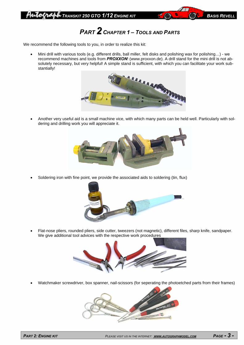
We recommend the following tools to you, in order to realize this kit:
Mini drill with various tools (e.g. different drills, ball miller, felt disks and polishing wax for polishing…) - we recommend machines and tools from PROXXON! (www.proxxon.de). A drill stand for the mini drill is not ab-solutely necessary, but very helpful! A simple stand is sufficient, with which you can facilitate your work sub-stantially!
Another very useful aid is a small machine vice, with which many parts can be held well. Particularly with sol-dering and drilling work you will appreciate it.
Soldering iron with fine point, we provide the associated aids to soldering (tin, flux)
Flat-nose pliers, rounded pliers, side cutter, tweezers (not magnetic), different files, sharp knife, sandpaper. We give additional tool advices with the respective work procedures
Watchmaker screwdriver, box spanner, nail-scissors (for seperating the photoetched parts from their frames)

TRANSKIT 250 GTO 1/12 ENGINE KIT BASIS REVELL Au
PART 2: ENGINE KIT PLEASE VISIT US IN THE INTERNET: WWW.AUTOGRAPHMODEL.COM PAGE - 4 -
tograph
PART 22 CHAPTER 1 – TOOLS AND PARTS
RS RESINE CAST PARTS RS
RS01 Cylinder head
Amount: 2
RS02 Sump
Amount: 1
RS03 Engine casing
Amount: 1
RS04 Sump r s Amount: 1
RS05 Sump l s
Amount: 1
RS06 Cylinder head cover r s
Amount: 1
RS07 Cylinder head cover l s
Amount: 1
RS08 Clutch bell Amount: 1
RS09 Flywheel casing lower
Amount: 1
RS10 Starter
Amount: 1
RS11 Distributor cap
Amount: 2
RS12 Water pump Amount: 1
RS13 Timing gear
cover r s Amount: 1
RS14 Timing gear
cover l s Amount: 1
RS15 Flange
Amount: 1

TRANSKIT 250 GTO 1/12 ENGINE KIT BASIS REVELL Au
PART 2: ENGINE KIT PLEASE VISIT US IN THE INTERNET: WWW.AUTOGRAPHMODEL.COM PAGE - 5 -
tograph
RS RESINE CAST PARTS RS
RS16 Gearbox casing 1
Amount: 1
RS17 Timing gear cover
Amount: 1
RS18 Rear gearbox casing
Amount: 1
RS19 Gearbox casing 2
Amount: 1
RS20 Distributor Amount: 2
RS21 Flange
Amount: 1
RS22 Oil filter holder
Amount: 1
WM WHITE METAL CAST PARTS WM
WM01 Carburettor Amount: 6
WM02 Intake manifold
Amount: 3
WM03 Gear selector
casing Amount: 1
WM04 Water pipe Amount: 1
WM05 Oil filter
Amount: 1
WM06 Clutch lever Amount: 1
WM07 Oil filler neck fr
Amount: 1
WM08 Oil filler cap fr
Amount: 1
WM09 Alternator Amount: 1
WM10 Water pipe Amount: 1
WM11 Universal joint
part 1 Amount: 1
WM12 Spark plug boot
Amount: 12

TRANSKIT 250 GTO 1/12 ENGINE KIT BASIS REVELL Au
PART 2: ENGINE KIT PLEASE VISIT US IN THE INTERNET: WWW.AUTOGRAPHMODEL.COM PAGE - 6 -
tograph
WM WHITE METAL CAST PARTS WM
WM13 Water pipe Amount: 1
WM14 Oil pipe
Amount: 1
WM15 Ignition cable tube
Amount: 2
NS16 Oil filler cap Amount: 2
WM17 Pulley
(alternator) Amount: 1
WM18 Water pipeline
Amount: 1
WM19 Oil filler neck l s
Amount: 1
WM20 Pulley
Amount: 1
WM23 Oil filler neck r s
Amount: 1
WM21 Oil pipeline Amount: 1
CR22 Fuel line (chromed)
Amount: 1
H SOLDERING COMPONENTS H
Flux 1 bottle
Solder 1 ring

TRANSKIT 250 GTO 1/12 ENGINE KIT BASIS REVELL Au
PART 2: ENGINE KIT PLEASE VISIT US IN THE INTERNET: WWW.AUTOGRAPHMODEL.COM PAGE - 7 -
tograph
T VARIOUS PARTS T
T01 Trumpets
Amount: 12 Box 1
T02 Pin small Amount: 4
Bag 2
T03 Sleeve
1,5 x 3 mm Amount: 8
Box 1
T04 Pin big
Amount: 1 Bag 2
T05 Self adhesive aluminium foil 50 x 50 mm
Bag 1
T06 Brass rod
2 x 60 mm Amount: 4
Bag 2
T07 Cable black 0,6 mm
0,8 m Bag 1
T08 Brass tube 1,5 x 32
Amount: 12 Bag 2
T09 Sleeve
Amount: 16 Box 1
T10 Brass material 5 x 3 x 45 mm
Amount: 1 Bag 2
T11 Wire
0,4 x 150 mm Amount: 1
T12 Spring 0,75
mm (gas linkage)
10 mm Box 1
T13 sleeve
Amount: 2 Box 1
T14 Tube
inner 1,5 mm 50 mm Bag 1
T15 Tube
inner 2 mm 50 mm Bag 1
T16 Tube
inner 3 mm 50 mm Bag 1
T17 Yellow cable 1,2 mm 200 mm Bag 1
T18 Black cable 0,8 mm 200 mm Bag 1
L BRASS SLEEVES L
L41 Brass sleeve
2,7 x 1,3 mm Amount: 12
Box 1
L76 Brass sleeve
5,9 x 1,4 mm Amount: 1
Box 1
L109 Brass sleeve
3,5 x 2,7 mmAmount: 5
Box 1
L101 Brass sleeve
2,7 x 2,7 mmAmount: 1
Box 1

TRANSKIT 250 GTO 1/12 ENGINE KIT BASIS REVELL Au
PART 2: ENGINE KIT PLEASE VISIT US IN THE INTERNET: WWW.AUTOGRAPHMODEL.COM PAGE - 8 -
tograph
M S BOLTS AND NUTS S, M
M0 Hexagonal nut
W 1,0 mm 0,7 mm
Amount: 18 Box 2
M1 Hexagonal nut
W 1,5 mm 1,0 mm
Amount: 14 Box 2
M2 Hexagonal nut
W 2,0 mm 1,2 mm Amount: 1
Box 2
M5 Hexagonal nut
W 3,0 mm 1,7mm Amount: 1
Box 2
S1 Hexagonal bolt
W 1,5 mm 1,0 x 5 mm
Amount: 4 Box 2
S3 Hexagonal bolt
W 2,5 mm 1,4 x 10mm
Amount: 1 Box 2
S4 Watchmaker
screws Amount: 5 gr
Box 2
S5 Hexagonal bolt W 3,0 mm, 1,7 x 10mm Amount: 1
Box 2
H PHOTOETCHED PARTS PLATINE H
PART DESCRIPTION AMOUNT
PART DESCRIPTION AMOUNT
H1 Hose clamp 36 H2 Cable binder 36

TRANSKIT 250 GTO 1/12 ENGINE KIT BASIS REVELL Au
PART 2: ENGINE KIT PLEASE VISIT US IN THE INTERNET: WWW.AUTOGRAPHMODEL.COM PAGE - 9 -
tograph
M PHOTOETCHED PARTS PLATINE M
PART DESCRIPTION AMOUNT M1 Soldering template for engine stand 8 M2 Disk for engine stand 24 M3 Plate for engine stand 4 M4 Hose fixing 2 mm 4 M5 Plate on sump part 1 1 M6 Plate on sump part 2 1 M7 Plate on sump part 3 1 M8 Lattice on clutch bell (lower) 1
M10 Cylinder head gasket (for use) 2 M11 Flange for oil pipe (sump) 4 M12 Exhaust flange (single) 4 M13 Exhaust flange (double) 4 M14 Carburettor gasket 2 M15 Plate on carburettor part 1 6 M16 Plate on carburettor part 2 6 M17 Ferrari-script on cylinder head cover 4 M18 Flange on water channel front 4 M19 Flange on oil filler neck (lower) 4 M20 Plate for gas linkage on r s cylinder head (part 1) 1 M21 Cover on gearbox/universal joint part 1 1 M22 Cover on gearbox/universal joint part 2 1 M23 Plate on gearbox 1 M24 Ventilation plate on clutch bell 1 M25 Flange on water pipe (cylinder head rear) 2 M26 Ignition timing plate on water pump 1 M27 Cover on engine housing (in front of clutch bell) 1 M28 Joint in gas linkage (Weber carburettors) 6 M29 Butterfly valve lever (Weber Vergaser) 6 M30 Washer (big) 35 M31 Spanner 19/18 mm 2
PART DESCRIPTION AMOUNT M32 Spanner 17/16 mm 2 M33 Spanner 15/14 mm 2 M34 Spanner 13/12 mm 2 M35 Spanner 11/10 mm 2 M36 Spanner 9/8 mm 2 M37 Spanner 7/6 mm 2 M39 Lever for gas linkage on l s cylinder bank 4 M40 Lever for gas linkage 1 M41 Choke lever for Weber-Carburettors (l s) 6 M42 Holder for oil filler neck (r s) 2 M43 Ring for ignition cables on distributor 2 M44 Cover on timing chain casing (fr r s) 1 M45 Nut M8 70 M46 Holder for oil filler neck (l s) 1 M47 Joints for gas linkage 6 M48 Washer small 35 M49 Plate for gas linkage on r s cylinder (part 2) 1 M50 Cylinder head gasket (for decoration) 2 M51 Clamp for gas linkage spring 1 M52 Plate on Weber-Carburettors (complete) 1 M53 Gear selector 1 M54 Plate for exhaust flanges 2 M55 Exhaust gasket (single) 4 M56 Exhaust gasket (double) 4 M57 Cover on water pump part 1 1 M58 Cover on water pump part 2 1 M59 Cover on water pump part 3 1 M60 Cover on water pump part (left) 1 M61 Alternator holder 1 M62 Clamp for alternator 2

TRANSKIT 250 GTO 1/12 ENGINE KIT BASIS REVELL Au
PART 2: ENGINE KIT PLEASE VISIT US IN THE INTERNET: WWW.AUTOGRAPHMODEL.COM PAGE - 10 -
tograph
PART 22 CHAPTER 2 – GENERAL NOTES
GLUING
I use instant adhesive (Cyanacrylate) for most gluings on my models. This has the advantage that the connection is loadable after a short moment, so you can immediately continue working.
With not directly accessible splices the capillary effect en-sures that the adhesive, laid on with a needle or a tooth-pin, flows directly into the sticking gap and fixes it. If you use a high-quality, water-clear adhesive, it dries up nearly invisibly. We recommend products from LOCTITE. Modern adhesives, like LOCTITE, no longer produce a white precipitation. Nevertheless, if this should happen however once, then you can remove it with „Armor all“,a plastic pre-servative agent from the car accessories. With more strongly loaded splices I use 2-component-
epoxy adhesive or recently metall-glass adhesive from LOCTITE: This adhesive has the advantage that you can use it very finely proportioned, contrary to normal 2K-Epoxy. And it hardens out within shortest time. Process it as follows: Coat one side of the splice economically with the resin, the other side with the activator liquid. This immediately dries up invisibly. If you join now both parts, the adhesive hardens out within seconds. During this time adhesive remainders can still be well removed. This sticking method is almost perfectly suitable for model construction!
SOLDERING With many connections, particularly with the very high loaded, sticking is not useful as connection technique. You should solder here. The necessary aids you will receive from us: Fluxing agents and special solder. Do not use electronic solder o
Proceed as follows: Fix the parts in the necessary position, e.g. in the machine vice or by holding with the tweezers. Coat then the soldered connection by means of a fine brush with the flux. It flows also into the gap between the parts which can be fixed by the capillary effect. Now you take up somewhat from the tin with the (embarrassingly clean) soldering point and touch the soldering connection. The flux ensures for the fact that the tin flows cleanly and connects the parts. The quantity of the used solder is crucial. Some test attempts help you to measure this quantity. After soldering you must clean the soldered connection: The flux has the un-
pleasant characteristic that it lets the environment oxidize after some time, if it is not carefully removed. Wash therefore the finished soldered connection with clear water, or brush the place with a fine brass brush (mi All our photoetched parts can be soldered well with one another or with the screws. Particularly I solder the small watchmaker screws as levers or pins to related photoetched parts.
r other commercial tin solder!
-ni drill).

TRANSKIT 250 GTO 1/12 ENGINE KIT BASIS REVELL Au
PART 2: ENGINE KIT PLEASE VISIT US IN THE INTERNET: WWW.AUTOGRAPHMODEL.COM PAGE - 11 -
tograph
WATCHMAKER SCREWS
Dump contents of the plastic box on a piece of self adhesive foil. So you make sure that the tiny screws S4 are not lost immediately. In addition the different sizes can be arranged very well on this foil. You should make at least a rough as-sortment before beginning of the model construction - so you have the necessary amount of same screws in the crucial moment. And you will not be interrupted by a long timeto searc For gluing on in the model a 100% nonmagnetic tweezers is necessary - otherwise the magnetic characteristics of the screws make problems. I can recommend tools from the surgical need (100% stainless steel non magnetic) or tweez-ers from titanium. Here no remainder magnetism is present. However, with the purchase you should go safe, by testing
the magnetization with the help of some screws: As soon as to the point only one screw remains sticking to the tweezers, a certain remainder magnetism is present, which can disturb when working with this tweezers. Naturally you can use such tweezers for the work with the photoetched parts. Since they are made out of non-ferrous metal alloys, there is also no magnetic influence. By the multiplicity of different forms of the watchmaker screws you can use these on completely different way. Orien-tate with the photos and leave your creativity a bit of free space. In combination with the hexagon nuts M0 – M3 in-
-
h.
teresting effects result, like e.g. complete screw connections with plain washers (see building step 2-L1). Or you use photoetched part M45 as a put on nut, (see building step 2-M2 ).
TRANSKIT 250 GTO 1/12 ENGINE KIT BASIS REVELL Au
PART 2: ENGINE KIT PLEASE VISIT US IN THE INTERNET: WWW.AUTOGRAPHMODEL.COM PAGE - 12 -
tograph PART 22 CHAPTER 3 – BUILDING STEPS
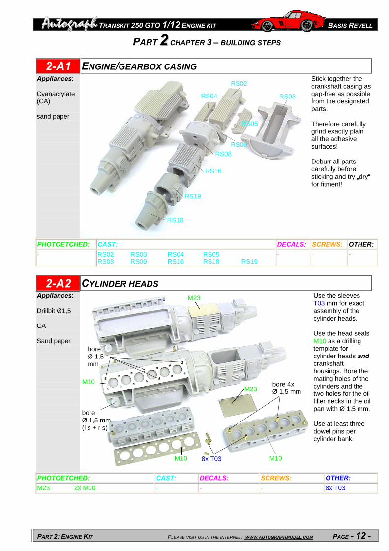
2-A1 ENGINE/GEARBOX CASING Appliances: Cyanacrylate (CA) sand paper
Stick together the crankshaft casing as gap-free as possible from the designated parts. Therefore carefully grind exactly plain all the adhesive surfaces! Deburr all parts carefully before sticking and try „dry“ for fitment!
RS02
RS04 RS03
RS05
RS09
RS08
RS16
RS19
RS18
PHOTOETCHED: CAST: DECALS: SCREWS: OTHER: - RS02 RS03 RS04 RS05
RS08 RS09 RS16 RS18 RS19 - - -
2-A2 CYLINDER HEADS Appliances: Drillbit Ø1,5 CA Sand paper
Use the sleeves T03 mm for exact assembly of the cylinder heads. Use the head seals M10 as a drilling template for cylinder heads and crankshaft housings. Bore the mating holes of the cylinders and the two holes for the oil filler necks in the oil pan with Ø 1.5 mm. Use at least three dowel pins per cylinder bank.
M23
M10
bore Ø 1,5 mm
bore 4x Ø 1,5 mm
M23
bore Ø 1,5 mm (l s + r s)
M10 M10 8x T03
PHOTOETCHED: CAST: DECALS: SCREWS: OTHER: M23 2x M10 - - - 8x T03

TRANSKIT 250 GTO 1/12 ENGINE KIT BASIS REVELL Au
PART 2: ENGINE KIT PLEASE VISIT US IN THE INTERNET: WWW.AUTOGRAPHMODEL.COM PAGE - 13 -
tograph
2-B1 TIMING CASING Appliances: CA
Put the timing housing RS17 in such a way to the engine casing, that the top side stands concisely and centrically to the cylinder banks (see arrows)! Then stick all attachments to the timing casing. Use a piece of brass profile (Ø 1.5 mm) for centering the M19 parts!
PHOTOETCHED: CAST:
M60
M57
M59 4x M19
RS17 RS15
RS17
Use a brass profile Ø 1,5 mm for centering
M60
2x M19
M54
RS15 M27
RS12
M58
WM10 RS22
RS12
DECALS: SCREWS: OTHER: 4x M19 2x M54 M27 M57 M58 M59 M60
RS17 RS22 RS12 WM10 RS15
- - -
2-B2 ENGINE CASING – ATTACHMENTS Appliances: Solder Flux CA
Solder the exhaust manifold flanges (in the vice) from photoetched parts M12, M13 and 20 equal screws S4. Leave the parts in their photoetched framework for this work (see photo). Use the Solder very economically! File surplus Solder from the back, so that the flanges can be stuck properly matching into the photoetched parts M54 (at the cylinder heads)!
PHOTOETCHED:
Einl en im Schraubstock
öten der StehbolzSolder in a vice! M8M7 M5 M6
M8
M18 10x S4
RS21
M12
M13M7 M18
M5
M13
M12
M6
CAST: DECALS: SCREWS: OTHER: M5 M18 M6 4x M12 M7 4x M13 M8
RS21
- 20x S4 (identical) -

TRANSKIT 250 GTO 1/12 ENGINE KIT BASIS REVELL Au
PART 2: ENGINE KIT PLEASE VISIT US IN THE INTERNET: WWW.AUTOGRAPHMODEL.COM PAGE - 14 -
tograph
2-C1 GEARBOX CASING – ATTACHMENTS Appliances: CA Solder Flux Drillbit Ø 1 mm Ø 1,4mm Ball miller
Solder Brass sleeve L76 with part M22! Stick on transmission exit! Put photoetched part M24 in recess at clutch bell. Drillings Ø 1 mm and 1.4 mm. The drillings Ø 1 mm (for the spark plugs) should be made somewhat diagonally to the exhaust flange set!
2 bores Ø 1 mm
M24
M22
L76
6 bores each side (Ø 1 mm) for spark plugs!
rework exhaust channels with a ball miller
bore Ø 1,4 mm
L76 + M22
solder
CAST: DECALS: SCREWS: OTHER: PHOTOETCHED: - - M22
M24 - L76
2-C2 ATTACHMENTS - PREPARATION Appliances: Drillbit Ø 0,7 mm Ø 1 mm Ø 1,6 mm Ball miller
Drill each part with diameters indicated in the picture! Countersink the two drillings at the starter RS10 with a ball Miller - here later a countersunk screw is used! Attention: Do not drill through WM15 – make dead-end-holes!
PHOTOETCHED: CAST: DECALS: SCREWS: OTHER:
2 drillings Ø 0,7 mm
bore Ø 0,7 mm
bore Ø 1,6 mm
6 drillings Ø 0,7 mm
WM15 RS07 RS06
RS11
RS10
2 drillings Ø 0,7 mm
7 drillings Ø 0,7 mm,
2 drillings Ø 0,7 mm, countersink with a ball miller
- - - RS06 RS07 RS10 2x RS11 2x WM15
-

TRANSKIT 250 GTO 1/12 ENGINE KIT BASIS REVELL Au
PART 2: ENGINE KIT PLEASE VISIT US IN THE INTERNET: WWW.AUTOGRAPHMODEL.COM PAGE - 15 -
tograph
2-D1 PAINTING - PREPARATION Appliances: Double sided tape Support Engine stand (Size acc. to drawing) Base board Rubber ring
You can now build yourself an engine mounting plate for the coming assembly procedures. The photo can serve as an accompanying suggestion. You should also separate the parts according to their future colours (see reference photo) and fix them with double-sided tape on a little wooden board. However you must leave sufficient space between the individual parts, in order to prevent spraying shades.
PHOTOETCHED: CAST: DECALS: SCREWS:
4x Messingbuchse L109 aufgelötet, T06 (Halter) Ø 2 mm
39 mm
29 m
m
Ø 2 mm
37 m
m
Fix all parts of the same colour (here: flat black) on a base plate for spraying!
OTHER: - - - - 4x L109
4x T06 (Ø 2 x 60 mm)
2-D2 CYLINDER HEAD COVER R S, STARTER Appliances: Solder Flux CA
Decorate the starter RS10 with suitable countersunk screws S4, the head cover RS06 with 16 resembling screws S4 and RS13 with 4x S4. Altogether you need at least 40 pieces of this sort! Note: only attach, do not stick the lever made from 2x M39!
Only attach, do not stick! Mounting will follow in chapter 2 M1
RS10
PHOTOETCHED: CAST: DECALS: SCREWS: OTHER: M17, M20, 2x M39 RS06, RS10, RS13 - 20x S4, 2x S4, 2x S4 (identical)
2x S4, S4 2x T02
M49 S4 2x M39
RS06 16x S4
2x S4 2x S4
2x S4
S4
RS13
2x T02, cut with grinding disk
4x S4M17

TRANSKIT 250 GTO 1/12 ENGINE KIT BASIS REVELL Au
PART 2: ENGINE KIT PLEASE VISIT US IN THE INTERNET: WWW.AUTOGRAPHMODEL.COM PAGE - 16 -
tograph
2-E1 CYLINDER HEAD L S, GEAR SELECTOR Appliances: Drillbit Ø 0,7 mm CA Tube Ø 14mm Round material Ø 10mm
Polish M53 with the mini drill. Leave the part in the framework during this work. For bending the part, a tube with an inner Ø of approx. 14 mm as well as a round material (approx. Ø 10 mm) is suitable (see sketch). Bore WM03 after gluing on M53 with 5x Ø 0.7 mm for using the 5 Screws S4 + 1 drilling Ø 0.7 mm for the gear lever.
5 +1 drillings Ø 0,7 mm
PHOTOETCHED: CAST: DECALS: SCREWS: OTHER: M53, M17, 2x M39
WM03 - 5x S4, 4x S4, 20x S4 (identical) 3x S4
2x T02 T04
2-E2 ADDING THE PREPARED PARTS, HOUSING BOLTS Appliances: CA
Decorate the complete engine housing with srews S4. (See Chapter 2 - General notes, Watchmaker screws). If I did not encount myself, these are 109 identical screws S4. Paint them in a thin, translucent black! Stick the cylinder head covers, the gear selector box and the starter on the engine housing.
PHOTOETCHED: CAST: DECALS: SCREWS: OTHER: M2
WM11 - 109x S4, 2x S4 (identical) M2+S4, S3
-
M53 (bend)WM03
WM11
4x S4
inner Ø ~ 14 mm outer Ø ~ 10 mm
15 m
m
10 m
m
5x S4
2x M39
S4 S4
M17
16x S4
2x T02, (shortened)
M53
Shorten and bend gear lever T04,
4x S4
S4
109x S4
M2+S4 S4
S4
MXX
2x S4
Anlasser
cylinder head r s
S4
mount turnable!
gear selector box cylinder head l s
starter
S3 + M2
M2 + S4

TRANSKIT 250 GTO 1/12 ENGINE KIT BASIS REVELL Au
PART 2: ENGINE KIT PLEASE VISIT US IN THE INTERNET: WWW.AUTOGRAPHMODEL.COM PAGE - 17 -
tograph
2-F1 DISTRIBUTOR, IGNITION CABLES L S Appliances: CA Fixture für WM12
Sequence: 1. Build up the distributor using parts RS11 and RS20, screw on cable ring M43, decorate the building group with S4(altogether 18x) 2. Spark plugs: paint WM12, bore (Ø 0.7) and attach! 3. Ignition cable tube: After completing the cylinder head screws with M45 (refer to step 2-M2), glue WM15 on the cylinder head cover, connect all cables (through cable run M43)
paint and drill WM12 (Ø 0,7 mm) – (make a wooden support for painting)
PHOTOETCHED: CAST: DECALS: SCREWS: OTHER: M43 36 x M45
WM15, 6x WM12 RS11 RS20
- 6x S4, 3x S4, 6x S4, 3x S4 (identical), S4
T07 (cable Ø 0,6 mm)
2-F2 DISTRIBUTOR, IGNITION CABLES R S Appliances: Solder Flux CA
Sequence like l s! Additionally: Make rev. counter drive from 2 screws S4 and stick it to the right distributor. Paint all exhaust channels in flat black and stick on photoetched gaskets M55 and M56!
PHOTOETCHED: CAST: DECALS: SCREWS: OTHER: M43, 4x M55, 4x M56
WM15, 6x WM12 RS11 RS20
- 6x S4, 3x S4, 6x S4, 3x S4 (identical), S4, 2x S4 (soldered), S4+M2
T07 (cable Ø 0,6 mm)
S4 M2
M43
RS11 RS20
3x S43x S4 S4
6x S4 6x S4
WM12 WM15
cable Ø 0,6 mm
bore Ø 0,7 mm
18 x M45
paint the exhaust channels flat black
M43
2xS4, soldered together as rev. counter drive
RS11 RS20
WM12
WM15
S43x S43x S46x S4
6x S44x M55 (l s + r s) 4x M56 (l s + r s) cable Ø 0,6 mm

TRANSKIT 250 GTO 1/12 ENGINE KIT BASIS REVELL Au
PART 2: ENGINE KIT PLEASE VISIT US IN THE INTERNET: WWW.AUTOGRAPHMODEL.COM PAGE - 18 -
tograph
2-G1 ENGINE STAND Appliances: Solder Flux
Bend the soldering assistances upwards and stick a small piece of self adhesive aluminium foil over it, so the stands won’t be soldered to the photoetched frame. Hold the parts in position during soldering.
nut M1 M3 M1 S1
After soldering the stands: paint them depending on your personal choice
Solder all!
12x T08
Fix it during soldering i. e. with hex. tool or tweezers!
12x M2
PHOTOETCHED: CAST: DECALS: SCREWS: OTHER: 4x M1, 12x M2 4x M3
- - 4x M1 4x S1
T05 (self adhesive aluminium foil) 12x T08
2-G2 CARBURETTORS - CONNECTION Appliances: Sand paper Drillbit Ø 0,6 mm
Carefully deburr the carburettors, grind the upper and lower contact areas to level seat. Plug together M15, M52 and 12 trumpets T01 (do not stick!). Then bore the holes with Ø 0.7 mm, pay attention to good alignment of the carburettors. Screw together M16, M15, M52 and WM1 using 12x S4.
eventuell grind a bit if the trumpets don’t fit properly!
Fix with 12x S4 M16 M15 M52
M52 M15
M16 12x S4 WM01
drill Ø 0,7 mm
PHOTOETCHED: CAST: DECALS: SCREWS: OTHER: 6x M15 6x M16 M52
6x WM01 - 12x S4 (identical) 12x T01

TRANSKIT 250 GTO 1/12 ENGINE KIT BASIS REVELL Au
PART 2: ENGINE KIT PLEASE VISIT US IN THE INTERNET: WWW.AUTOGRAPHMODEL.COM PAGE - 19 -
tograph
2-H1 CARBURETTORS - PREPARATION Appliances: Cyanacrylate (CA) Drillbit Ø 0,6 Drillbit Ø 0,8
Remove the trumpets T01 again! For good alignment when gluing the base plate M14 to the carburettors, use a vice. This is also useful when drilling the carbs.
carburettors r s:
drill Ø 0,8 mm
drill Ø 0,6 mm
carburettorsl s:
PHOTOETCHED: CAST: DECALS: SCREWS: OTHER: M14 - - - -
2-H2 CARBURETTORS – PREPARING THE TRUMPETS Appliances: CA Brass Brush Brass sleeve L101 as a template
Turn the trumpets T01 in your mini drill and polish them to a high gloss, i. e. with a fine brass brush. Make the Venturi tube from T09 und L41, glue it into the trumpets. Use L101to reach an equal level in every trumpet. Remove L101 - make all 12 trumpets in this way!
PHOTOETCHED: CAST: DECALS: OTHER: OTHER: - - - 12x L41
L101 12x T01 12x T09
drill Ø 0,8 mm
M14 (bended)
drill Ø 0,6 mm
brass sleeve L101 is only a template for equal levels inside the trumpets – do not glue!
12x L41
12x T01 polishing the trumpets
12x T09
Venturi tube after mounting the trumpets

TRANSKIT 250 GTO 1/12 ENGINE KIT BASIS REVELL Au
PART 2: ENGINE KIT PLEASE VISIT US IN THE INTERNET: WWW.AUTOGRAPHMODEL.COM PAGE - 20 -
tograph 2-I1 CARBURETTORS – FIXING THE TRUMPETS
Appliances: Cyanacrylate (CA) Ledge T10 to straighten the trumpets Rubber ring Round file
Use a vice for attaching the first row of trumpets to the carbs. Carefully adjust the trumpets using brass ledge T10 and a rubber ring. Glue with the help of a pin and cyanacrylate. File each of the second row of trumpets with a round file, attach, carefully adjust and glue them to the carburettors. Take care of perfect alignment of all trumpets – these parts are the first where one looks at!
filing the trumpets cond row) (se
PHOTOETCHED: CAST: DECALS: SCREWS: OTHER: - - - - T10
12 x T01
2-I2 CARBURETTORS – GAS LINKAGE 1 Appliances: CA Solder Flux
Hold all 6 parts M29 together with their frame in a vice, fold, and solder in 12x S4. Remove the frame of the levers M29 after they were fixed to the carbs. Every lever should stand in the same angle!
PHOTOETCHED: CAST: DECALS: SCREWS: OTHER: 6x M29 12x M30
- - 6x S4, 6x S4, 6x S4 (jeweils identisch)
-
Mounting the second row of
trumpets
6x M29 (with frame)
S4
S4 S4 (screw in deep)
M29 2x M30
12x M30
6x S4 (solder)
6x S4 (for mounting)
6x S4
File the second row of trumpets T01 here
T10
S4 (scew in deep)

TRANSKIT 250 GTO 1/12 ENGINE KIT BASIS REVELL Au
PART 2: ENGINE KIT PLEASE VISIT US IN THE INTERNET: WWW.AUTOGRAPHMODEL.COM PAGE - 21 -
tograph
2-J1 CARBURETTORS – GAS LINKAGE 2 Appliances: Cyanacrylate (CA)
Cut approx. 50 mm from the straight wire T11, bend 90° (so that the 12 attached nuts do not fall down). For manufacturing gas linkage, leave the parts M28 in the framework! Put the bar with the nuts M0 on the photoetched framework (see pic.) and bend all parts around it. Glue one nut M0 to each side of M28. Then cut out and shorten the bar!
6x M28, bend round the gas linkage T11.
6xM1 6x M28 12x M0 S4 M40
After mounting the linkage, glue (or solder) the folded lever M40 to the bar.
T11
PHOTOETCHED: CAST: DECALS: SCREWS: OTHER: 6x M28 - - S4, 12x M0, 6x M1 T11,
2-J2 CARBURETTORS – LEFT SIDE Appliances: CA thin brown wire
Cut 6 parts from the isolation of a thin brown wire, length approx. 2,5 mm each. Put these onto photoetched parts M41. When attaching the choke levers to the carburettors, make sure that all levers have the same angle.
6x S4
6 Stück Isolier- schlauch 2,5 mm
remove the frame of the choke levers M41 after mounting to the carbs with 6x S4
PHOTOETCHED: CAST: DECALS: SCREWS: OTHER: 6x M41- - - 12x S4 (identical) 6x thin brown isolation tube
M41 6x S4

TRANSKIT 250 GTO 1/12 ENGINE KIT BASIS REVELL Au
PART 2: ENGINE KIT PLEASE VISIT US IN THE INTERNET: WWW.AUTOGRAPHMODEL.COM PAGE - 22 -
tograph
2-K1 INTAKE MANIFOLD Appliances: File CA Model glue
Bend photoetched part M14 (90°), deburr WM02 carefully. Before gluing, take care that all 3 intake manifolds WM02 stand in the same angle. If not, turn round 180°. It is most important, that you try all parts “dry” before finally gluing the whole unit to the engine with a gap filling adhesive. The whole intake manifold must be mounted exactly horizontal!
PHOTOETCHED: CAST: DECALS: SCREWS: OTHER: M14 3x WM02 - - -
exactly horizontal!
M14 use gap-filling adhesive!
M14 3x WM02 eventually turn 180°
2-K2 CARBURETTORS, FILLER NECK, OIL FILTER, PULLEY Appliances: CA Sand paper Mini-Drill
Align the carbs exactly between the cylinders! Use the mini drill for grinding the cast parts WM08 and WM20: Fill the ignition order plate M26 with black colour and grind back to the metal with fine emery paper!
WM08 - grind in the mini drill
WM20 WM07
M26
S4 M1
WM05 WM08
hold WM20 in the mini drill for grinding
tool holder
5x S4
PHOTOETCHED: CAST: DECALS: SCREWS: OTHER: M26 WM05
WM07 WM08 WM20
- 5x S4 S4 M1
-

TRANSKIT 250 GTO 1/12 ENGINE KIT BASIS REVELL Au
PART 2: ENGINE KIT PLEASE VISIT US IN THE INTERNET: WWW.AUTOGRAPHMODEL.COM PAGE - 23 -
tograph
2-L1 ALTERNATOR Appliances: Cyanacrylate (CA) Drillbit
V-belt: cut a piece of black cable (Ø approx. 0,8 mm) and remove the inner cores. Cut the isolation to 59 mm. Form a ring using a piece of thin wire to connect the two ends.
Grind WM17 in the mini drill (see picture).
PHOTOETCHED: CAST: DECALS: SCREWS: OTHER: M61 M62 2x M48 2x M45
WM09 WM17
- S4 S4 S4 M1
black isolation L = 59 mm piece of wire
2-L2 OIL LINE, FILLER NECK R S Appliances: CA Sand paper
Attention: do not confuse parts WM19 and WM23! Therefore try “dry” before gluing! Polish NS16 with the help of the mini drill.
PHOTOETCHED: CAST: DECALS: SCREWS: OTHER: M11 M42 2x M45 2x M48
WM14 NS16 WM23
- 2xS4 S5 (shorten) M5-
T13
cable isolation, l = 59 mm
Fold M61, bore (Ø1,0) and mount with S4 to the engine. Take care of good alignment of the two pulleys!
S4 WM09 WM17 S4 M1
piece of wire
M61
M62 2x M48 2x M45
fold
S4 M61 (screw to the housing)
M11 2x S4 WM14 T13 M5 M42
NS16 WM23
M45 M48
fold
S5 (shorten)

TRANSKIT 250 GTO 1/12 ENGINE KIT BASIS REVELL Au
PART 2: ENGINE KIT PLEASE VISIT US IN THE INTERNET: WWW.AUTOGRAPHMODEL.COM PAGE - 24 -
tograph
2-M1 GAS LINKAGE 3 Appliances: CA Solder + flux
Cut 2 pieces from the 0,4 mm straight wire T11: 1. l = 17 mm 2. l = 28 mm
(+ 1 mm folded)
Solder 3 joints M47 to the ends. Leave M47 in the frame for this work. Cut out afterwards.
ching return spring from the supported material T12.
Form a mat
PHOTOETCHED: CAST: OTHER: SCREWS: DECALS: 2x M39 3x M47 3x M48 M51
- T11 (17 mm) T11 (28 + 1 mm) T12
2x S4 M1
-
l=17 mm
M51 M47
T12 2x M47, T11 (17 mm) 3x M48 2x S4 (solder) M1 2x M39
l=28 mm
2x S4 soldered to the levers M39
2-M2 OIL LINE, FILLER NECK L S, CLUTCH LEVER Appliances: CA Sand paper Mini-drill (for NS16)
The cut-off rest of WM21 will only be needed, when the engine goes into the car. Fix the 2 filler necks WM19 and WM23 with a hose clamp H1 each. The cylinder head screws look better, when you decorate each one with a photoetched nut M45. Polish NS16 in the mini drill (as described in chapter 2-L2)
PHOTOETCHED: CAST: OTHER: SCREWS: OTHER: 3x H1 M46 several M45 M11
NS16 WM19 WM21 WM06
T15
2x S4 3xS4 2x S4 M1
Making the hose clamps
H1 S4
2x S4 M11 T15
WM21 (cut through) M45 (put on S4 to indicate hex. nuts)
clutch lever
2x S4 M1 WM06
NS16 H1+S4 WM19 M46 (grind)

TRANSKIT 250 GTO 1/12 ENGINE KIT BASIS REVELL Au
PART 2: ENGINE KIT PLEASE VISIT US IN THE INTERNET: WWW.AUTOGRAPHMODEL.COM PAGE - 25 -
tograph
2-N1 WATER PIPELINE Appliances: CA
Bend water line WM18 to a correct shape before attaching.
Put the tubes T14, T15 und T16 onto a matching piece of round material (vice!), mount the hose clamps H1 and then attach the finished tubing.
T14
4x S4 T16
PHOTOETCHED: CAST: OTHER: SCREWS: DECALS: 6x H1 M18 2xM25
WM04 WM13 WM18
L109 T14 (6 mm) T15 (10 mm) T16 (10, 12 mm)
6x S4 4x S4 2x S4
2-N2 DECORATION Appliances: CA Polishing wax Polishing disk
Polish the spanners M31 – M37 to a high gloss. Leave all the parts in the frame for this work. Then cout out the inner frame, fold in the middle and stick together with CA. Use for decoration. The 2 cylinder head gaskets M50 are also for decoration purposes.
PHOTOETCHED: CAST: DECALS: SCREWS: OTHER: M31 – M37 2x M50
- - - -
T13
WM13 (cut through) T16 (10 mm)
L109 S4 H1 T16 (12 mm)
M18 2x S4 WM04 S4 H1
M25 WM18 T14 WM13
stick M18 to the engine front,
2x S4 for deco
T15
4x S4 4x H1
T16
M25 WM18

TRANSKIT 250 GTO 1/12 ENGINE KIT BASIS REVELL Au
PART 2: ENGINE KIT PLEASE VISIT US IN THE INTERNET: WWW.AUTOGRAPHMODEL.COM PAGE - 26 -
tograph 2-O1 FUEL LINE
Appliances: Loctite-glue Glas-Metal Mini-drill+ cutting disk
Seperate the chromed brass fuel line CR22 from the sprue at the indicated spots. Try „dry“ before finally mounting, eventually bend a little. Attention: the chrome will crack, if you bend too much. Add yellow cable T17 with 2 shortened sleeves T09. Attach another 2 sleeves T09 at each end of the fuel line. That was it!
PHOTOETCHED: CAST: OTHER: SCREWS: DECALS: CR22 4x T09
2x T17 1x T18
2-O2 FINISHED!
T09 (shortened) T17 T09 (shortened) CR22
T09 (shortened)
T17
T18
T09 (shortened)
= seperate here