audel hvac fundamentals volume 2 · 2013-07-17 · hvac fundamentals volume 2 heating system...
TRANSCRIPT

Audelª
HVAC FundamentalsVolume 2
Heating SystemComponents, Gas and OilBurners, and Automatic
Controls
All New 4th Edition
James E. Brumbaugh
FFIRS.qxd 6/16/04 8:37 AM Page i Quark03 Quark03:Desktop Folder:Chapter-FM:
Vice President and Executive Group Publisher: Richard SwadleyVice President and Executive Publisher: Robert IpsenVice President and Publisher: Joseph B. WikertExecutive Editor: Carol A. LongAcquisitions Editor: Katie FeltmanEditorial Manager: Kathryn A. MalmSenior Production Manager: Fred BernardiDevelopment Editor: Kenyon BrownProduction Editor: Vincent KunkemuellerText Design & Composition: TechBooks
Copyright 2004 by Wiley Publishing, Inc., Indianapolis, Indiana. All rights reserved.
Published simultaneously in Canada
No part of this publication may be reproduced, stored in a retrieval system, or transmitted in anyform or by any means, electronic, mechanical, photocopying, recording, scanning, or otherwise,except as permitted under Section 107 or 108 of the 1976 United States Copyright Act, withouteither the prior written permission of the Publisher, or authorization through payment of the appro-priate per-copy fee to the Copyright Clearance Center, Inc., 222 Rosewood Drive, Danvers, MA01923, (978) 750-8400, fax (978) 646-8700. Requests to the Publisher for permission should beaddressed to the Legal Department, Wiley Publishing, Inc., 10475 Crosspoint Blvd., Indianapolis, IN46256, (317) 572-3447, fax (317) 572-4447, E-mail: [email protected].
Limit of Liability/Disclaimer of Warranty: The publisher and the author make no representa-tions or warranties with respect to the accuracy or completeness of the contents of this workand specifically disclaim all warranties, including without limitation warranties of fitness for aparticular purpose. No warranty may be created or extended by sales or promotional materi-als. The advice and strategies contained herein may not be suitable for every situation. Thiswork is sold with the understanding that the publisher is not engaged in rendering legal,accounting, or other professional services. If professional assistance is required, the services ofa competent professional person should be sought. Neither the publisher not the author shallbe liable for damages arising herefrom. The fact that an organization or Web site is referred toin this work as a citation and/or a potential source of further information does not mean thatthe author or the publisher endorses the information the organization or Web site may provideor recommendations it may make. Further, readers should be aware that Internet Web siteslisted in this work may have changed or disappeared between when this work was written andwhen it is read.
For general information on our other products and services, please contact our Customer CareDepartment within the United States at (800) 762-2974, outside the United States at (317) 572-3993 or fax (317) 572-4002.
Trademarks: Wiley, the Wiley Publishing logo, and Audel are trademarks or registered trade-marks of John Wiley & Sons, Inc., and/or its affiliates. All other trademarks are the property oftheir respective owners. Wiley Publishing, Inc., is not associated with any product or vendormentioned in this book.
Wiley also publishes its books in a variety of electronic formats. Some content that appears inprint may not be available in electronic books.
Library of Congress Cataloging-in-Publication Data:
Printed in the United States of America
10 9 8 7 6 5 4 3 2 1
FFIRS.qxd 6/16/04 8:37 AM Page ii Quark03 Quark03:Desktop Folder:Chapter-FM:
eISBN: 0-7645-7436-1

For Laura, my friend, my daughter.
FFIRS.qxd 6/16/04 8:37 AM Page iii Quark03 Quark03:Desktop Folder:Chapter-FM:

FFIRS.qxd 6/16/04 8:37 AM Page iv Quark03 Quark03:Desktop Folder:Chapter-FM:

v
Contents
Introduction xv
About the Author xvi
Chapter 1 Oil Burners 1Gun-Type Oil Burners 3
Construction Details 3Operating Principles 10
Flame-Retention Head Burners 16High-Static Oil Burners 16Rotary Oil Burners 16Vaporizing (Pot-Type) Oil Burners 18Combination Oil and Gas Burners 18Fuel Pump 19
Single-Stage Fuel Pump 21Two-Stage Pump 25Fuel Pump Capacity 26Fuel Pump Service and Maintenance 26Priming Fuel Pumps 29Adjusting Fuel Pump Pressure 29Troubleshooting Fuel Pumps 31
Fuel Supply Tank and Line 32Oil Burner Nozzles 32Electrodes 36
Troubleshooting Electrodes 37Servicing Electrodes 37
Oil Burner Air System 37Primary Safety Control Service 40Installing an Oil Burner 40Starting an Oil Burner 42Air Delivery and Blower Adjustment 43Combustion Testing and Adjustments 43Troubleshooting Oil Burners 48
FTOC.qxd 6/16/04 8:39 AM Page v Quark03 Quark03:Desktop Folder:Chapter-FM:

vi Contents
Chapter 2 Gas Burners 57Operating Principles 57Electrical Circuits 61Automatic Controls 61Types of Gas Burners 63Integral-Type Gas Burners 65Gas Conversion Burners 66Gas Conversion Burner Combustion
Chambers 67Gas Piping for Conversion Burners 68Venting and Ventilation 71Safety Precautions 72Troubleshooting Gas Burners 73
Chapter 3 Coal Firing Methods 77Coal-Firing Draft Requirements 77Firing Anthracite Coal 78Firing Bituminous Coal 80Firing Semibituminous Coal 81Stoker Firing 81Stoker Construction 84Stoker Automatic Controls 86Stoker Operating Instructions 90Coal Selection 91Starting the Fire 91Natural Stack Draft 91Manual Air Adjustment 92Automatic Air Control 92Changing Coal Feeds 92Motor Overload Protection 92Transmission Overload
Protection 93Removal of Obstruction 93Lubrication 93Summer Service 93How to Remove Clinkers 94How to Adjust Coal Feed 94
FTOC.qxd 6/16/04 8:39 AM Page vi Quark03 Quark03:Desktop Folder:Chapter-FM:

Contents vii
How to Adjust Air Supply 94Troubleshooting Coal Stokers 94
Chapter 4 Thermostats and Humidistats 99Automatic Control Systems 99Temperature Control Circuits 100Thermostats 100
Thermostat Components 105Thermostat Terminal Identification 109Thermostat Anticipators 109Types of Thermostats 119Room Thermostats 119Programmable Thermostats 125Insertion Thermostats 125Immersion Thermostats 126Cylinder Thermostats 127Boiler Thermostats 129Remote-Bulb Thermostats 129Proportional Thermostats 132Outdoor Thermostats 132
Troubleshooting Thermostats 134Humidistats 134
Location of Room Humidistats 140Troubleshooting Humidistats 142
Chapter 5 Gas and Oil Controls 145Gas Controls 145
Gas Control Circuits 146Gas Burner Primary Control 146
Servicing a Gas Burner Primary Control 151Gas Valves 153
Solenoid Gas Valves 153Solenoid Coils 158Direct-Acting Heat Motor Valves 163Diaphragm Valves 164
Pressure Regulators 166Pressure Switches 170
FTOC.qxd 6/16/04 8:39 AM Page vii Quark03 Quark03:Desktop Folder:Chapter-FM:
viii Contents
Automatic Pilot Safety Valve 174Thermopilot Valves 178Thermocouples 181
Troubleshooting Thermocouples 183Thermopiles (Pilot Generators) 184Pilot-Operated Diaphragm Valves 185Combination Gas Valves 187
Standing Pilot Combination Gas Valves 187
Continuous Pilot Dual Automatic Gas Valve 191
Universal Electronic Ignition Combination Gas Valve 194
Pilot Burners 194Installing a Pilot Burner 198Replacing the Pilot Burner Orifice 200Lighting the Pilot 201Pilot Flame Adjustment 202Main Burner Ignition 202
Pilot-Pressure Switch 203Electronic Ignition Modules 203
Intermittent Pilot Ignition Module 204Direct-Spark Ignition Module 207
Hot-Surface Ignition Module 208Igniters 211Flame Sensors 214
Mercury Flame Sensors 216Oil Controls 217Oil Valves 217Oil Burner Primary Control 219Cadmium Cell Primary Controls 220Stack Detector Primary Control 223Combination Primary Control and
Aquastat 227Troubleshooting the Oil Burner Primary
Control 231
FTOC.qxd 6/16/04 8:39 AM Page viii Quark03 Quark03:Desktop Folder:Chapter-FM:
Chapter 6 Other Automatic Controls 233Fan Controls 233
Fan Control 233Air Switch 236Fan Relays 237Fan Center 239Fan Manager 241Fan Timer Switch 241Fan Safety Cutoff Switch 242
Limit Controls 244Limit Control 244Secondary High-Limit Switch 248Combination Fan and Limit Control 251
Switching Relays 256Impedance Relays 259Heating Relays/Time-Delay Relays 261Potential Relay 263Pressure Switches 265Sail Switches 266Other Switches and Relays 268Sequence Controllers 269Contactors 275
Troubleshooting Contactors 277Cleaning Contactors 280Replacing Contactors 280
Motor Starter 281Overload Relay Heater 281Inherent Protector 282Pilot Duty Motor Protector 283Capacitors 284
Troubleshooting Capacitors 287Replacing Capacitors 287
High-Pressure Cutout Switch 288Low-Pressure Cutout Switch 289Transformers 290
Sizing Transformers 291
Contents ix
FTOC.qxd 6/16/04 8:39 AM Page ix Quark03 Quark03:Desktop Folder:Chapter-FM:
x Contents
Installing Transformers 291Control Panels 293
Chapter 7 Ducts and Duct Systems 295Codes and Standards 295Types of Duct Systems 295Perimeter Duct Systems 296Extended Plenum Systems 297Crawl-Space Plenum Systems 297Duct Materials 298Duct System Components 299Supply Air Registers, Grilles, and
Diffusers 301Return Air and Exhaust Air Inlets 302Duct Run Fittings 303Air Supply and Venting 305Duct Dampers 305Damper Motors and Actuators 313Installing Damper Motors 316Troubleshooting Damper Motors 320Blowers (or Fans) for Duct
Systems 321Designing a Duct System 322Duct System Calculations 323Duct Heat Loss and Gain 324Air Leakage 325Duct Insulation 325Equal Friction Method 326Balancing an Air Distribution System 331Duct Maintenance 331Roof Plenum Units 332Mobile Home Duct Systems 333Proprietary Air Distribution Systems 336Duct Furnaces 338Electric Duct Heaters 347
FTOC.qxd 6/16/04 8:39 AM Page x Quark03 Quark03:Desktop Folder:Chapter-FM:

Chapter 8 Pipes, Pipe Fittings, and Piping Details 355Types of Pipe Materials 355
Wrought-Iron Pipe 356Wrought-Steel Pipe 363Galvanized Pipe 363Copper and Brass Pipes and Tubing 363Plastic Tubing 367Synthetic Rubber Hose 369Composite Tubing 369
Pipe Fittings 369Classification of Pipe Fittings 370Extension or Joining Fittings 370Reducing or Enlarging Fittings 378Directional Fittings 380Branching Fittings 380Shutoff or Closing Fittings 382Union or Makeup Fittings 382Flanges 382Pipe Expansion 382
Valves 384Pipe Threads 384Pipe Sizing 384Sizing Steam Pipes 385Sizing Hot-Water (Hydronic)
Pipes/Tubing 393Pipe Fitting Measurements 396Calculating Offsets 397
First Method 400Second Method 401Third Method 401Fourth Method 403
Pipe Supports 403Joint Compound 403Pipe Fitting Wrenches 406Pipe Vise 409
Contents xi
FTOC.qxd 6/16/04 8:39 AM Page xi Quark03 Quark03:Desktop Folder:Chapter-FM:

xii Contents
Installation Methods 410Pipe Cutting 410Pipe Threading 412Pipe Reaming 414Pipe Cleaning 414Pipe Tapping 414Pipe Bending 415Assembling and Make–Up 415Nonferrous Pipes, Tubing, and Fittings 420Soldering Pipe 420Brazing Pipes 424Braze Welding Pipe 425Welding Pipe 425Gas Piping 429Insulating Pipes 429Piping Details 430
Connecting Risers to Mains 431Connections to Radiators or
Convectors 431Lift Fittings 431Drips 432Dirt Pockets 434Siphons 434Hartford Connections 434Making Up Coils 434Relieving Pipe Stress 436Swivels and Offsets 439
Eliminating Water Pockets 440Pressure Tests 444
Chapter 9 Valves and Valve Installation 445Valve Components and Terminology 445
Valve Materials 451Globe and Angle Valves 454Gate Valves 456Check Valves 458
FTOC.qxd 6/16/04 8:39 AM Page xii Quark03 Quark03:Desktop Folder:Chapter-FM:

Contents xiii
Stop Valves 463Butterfly Valves 465Two-Way Valves 467
Three-Way Valves 469Y Valves 469Valve Selection 469Troubleshooting Valves 472
Valve Stuffing-Box Leakage 474Valve Seat Leakage 474Damaged Valve Stems 475
Automatic Valves and Valve Operators 475Valve Pipe Connections 487Valve Installing Pointers 489Soldering, Brazing, and Welding Valves
to Pipes 492Soldering or Silver-Brazing Procedure 494Butt-Welding Procedure 495Socket-Welding Procedure 496
Chapter 10 Steam and Hydronic Line Controls 497Steam and Hydronic System Pumps 497
Condensate Pumps 497Circulators (Water-Circulating Pumps) 505Circulator Selection 511
Steam Traps 518Sizing Steam Traps 519Steam Trap Maintenance 520
Automatic Heat-Up 520Installing Steam Traps 522Float Traps 523Thermostatic Traps 524Balanced-Pressure Thermostatic
Steam Traps 525Maintenance 526
Float and Thermostatic Traps 526Thermodynamic Steam Traps 529
FTOC.qxd 6/16/04 8:39 AM Page xiii Quark03 Quark03:Desktop Folder:Chapter-FM:

xiv Contents
Bucket Traps 530Flash Traps 534Impulse Traps 534Tilting Traps 536Lifting Traps 537Boiler Return Traps 537Expansion Tanks 540
Closed Steel Expansion Tanks 541Diaphragm Expansion Tanks 543Sizing Expansion Tanks 543Troubleshooting Expansion Tanks 544
Air Eliminators 545Pipeline Valves and Controls 547
Temperature Regulators 548Electric Control Valves (Regulators) 548Water-Tempering Valves 550Hot-Water Heating Control 554Flow Control Valve 558Electric Zone Valve 559Balancing Valves, Valve Adapters,
and Filters 561Manifolds 564Pipeline Strainers 565
Appendix A Professional & Trade Associations 567
Appendix B Manufacturers 579
Appendix C Data Tables 591
Appendix D Conversion Tables 629
Index 639
FTOC.qxd 6/16/04 8:39 AM Page xiv Quark03 Quark03:Desktop Folder:Chapter-FM:
xv
IntroductionThe purpose of this series is to provide the layman with an introduc-tion to the fundamentals of installing, servicing, troubleshooting,and repairing the various types of equipment used in residential andlight-commercial heating, ventilating, and air conditioning (HVAC)systems. Consequently, it was written not only for the HVAC tech-nician and others with the required experience and skills to do thistype of work but also for the homeowner interested in maintainingan efficient and trouble-free HVAC system. A special effort wasmade to remain consistent with the terminology, definitions, andpractices of the various professional and trade associations involvedin the heating, ventilating, and air conditioning fields.
Volume 1 begins with a description of the principles of thermaldynamics and ventilation, and proceeds from there to a generaldescription of the various heating systems used in residences andlight-commercial structures. Volume 2 contains descriptions of theworking principles of various types of equipment and other compo-nents used in these systems. Following a similar format, Volume 3includes detailed instructions for installing, servicing, and repairingthese different types of equipment and components.
The author wishes to acknowledge the cooperation of the manyorganizations and manufacturers for their assistance in supplyingvaluable data in the preparation of this series. Every effort wasmade to give appropriate credit and courtesy lines for materials andillustrations used in each volume.
Special thanks is due to Greg Gyorda and Paul Blanchard (WattsIndustries, Inc.), Christi Drum (Lennox Industries, Inc.), DaveCheswald and Keith Nelson (Yukon/Eagle), Bob Rathke (ITT Bell &Gossett), John Spuller (ITT Hoffman Specialty), Matt Kleszezynski(Hydrotherm), and Stephanie DePugh (Thermo Pride).
Last, but certainly not least, I would like to thank Katie Feltman,Kathryn Malm, Carol Long, Ken Brown, and Vincent Kunkemueller,my editors at John Wiley & Sons, whose constant support andencouragement made this project possible.
James E. Brumbaugh
FLAST.qxd 6/16/04 8:38 AM Page xv Quark03 Quark03:Desktop Folder:Chapter-FM:

About the AuthorJames E. Brumbaugh is a technical writer with many years of expe-rience working in the HVAC and building construction industries.He is the author of the Welders Guide, The Complete RoofingGuide, and The Complete Siding Guide.
xvi
FLAST.qxd 6/16/04 8:38 AM Page xvi Quark03 Quark03:Desktop Folder:Chapter-FM:
Chapter 1Oil BurnersAn oil burner is a mechanical device used to prepare the oil forburning in heating appliances such as boilers, furnaces, and waterheaters. The term oil burner is somewhat of a misnomer becausethis device does not actually burn the oil. It combines the fuel oilwith the proper amount of air for combustion and delivers it to thepoint of ignition, usually in the form of a spray.
The fuel oil is prepared for combustion either by vaporization orby atomization. These two methods of fuel oil preparation are usedin the three basic types of oil burners employed in commercial,industrial, and residential heating. The following are the three basictypes of oil burners:
1. Gun-type (atomizing) oil burners.2. Vaporizing (pot-type) oil burners.3. Rotary oil burners.
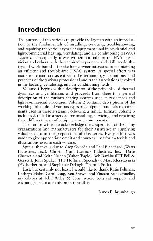
Gun-type atomizing oil burners are available as either low-pressureor high-pressure types (see Figures 1-1, 1-2, and 1-3). Both are usedin residential heating applications with the latter being by far themore popular of the two. The remainder of this chapter is devoted toa description of the gun-type high-pressure atomizing oil burnersused in residential and light commercial oil heating systems.
1
Figure 1-1 Basic shape of a gun-type oil burner.(Courtesy Stewart-Warner Corp.)
GB039-1317G-P01[001-056].qxd 6/8/04 7:11 PM Page 1 Quark03 Quark03:Desktop Folder:repro:

The advantage of the vaporizing (pot-type) oil burner is its lowoperating cost. It is the least expensive to use, but it has limitedheating applications. It is currently used only in small structureslocated in milder climates. Vaporizing burners can be divided intothe three following types:
1. Natural-draft pot burners.2. Forced-draft pot burners.3. Sleeve burners.
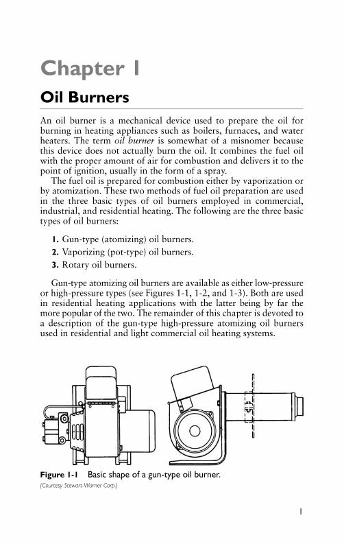
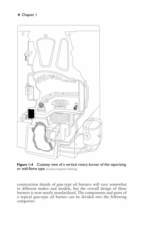
Rotary oil burners are commonly used in the heating systems ofcommercial or industrial buildings, although they can and have beenused for residential heating applications (see Figures 1-4 and 1-5).The following types of rotary oil burners are available for heatingpurposes:
2 Chapter 1
DRAFT TUBE
PUMP STRAINER AND VALVE
UNIT
COUNTER-BALANCEDDRAFT SHUTTER
LEGS FOR PEDESTAL-MOUNTEDATTACHMENT
FAN HOUSING
MOTOR
BUILT-INMOTOR
PROTECTOR
PYPEX FIRE INSPECTION HOLES
OIL FEED TUBEFROM PUMP TO
IGNITION ANDFIRING ASSEMBLY PLATE
TRANSFORMER
Figure 1-2 Principal components of an S.T. Johnson gun-type oilburner. (Courtesy S.T. Johnson Company)
GB039-1317G-P01[001-056].qxd 6/8/04 7:11 PM Page 2 Quark03 Quark03:Desktop Folder:repro:

• Vertical rotary burners• Horizontal rotary burners• Wall-flame rotary burners
Gun-Type Oil BurnersGun-type, high-pressure atomizing oil burners are sometimescalled sprayers or atomizing burners because they spray the fueloil instead of vaporizing it. They are also referred to as gun orpressure oil burners because the oil is forced under pressurethrough a special gun-like atomizing nozzle. The liquid fuel isbroken up into minute liquid particles or globules to form thespray.
Construction DetailsThe principal components and parts of a gun-type, high-pressureatomizing oil burner used in residential and light commercial oilheating systems are illustrated in Figures 1-6 and 1-7. The
Oil Burners 3
MOTORFAN
FUEL LINE
STRAINER
PUMPTRANSFORMER AIR TUBE
REFRACTORY FIREPOT
Figure 1-3 Gun-type oil burner firing into furnace combustionchamber. (Courtesy U.S. Department of Agriculture)
GB039-1317G-P01[001-056].qxd 6/8/04 7:11 PM Page 3 Quark03 Quark03:Desktop Folder:repro:
construction details of gun-type oil burners will vary somewhatin different makes and models, but the overall design of theseburners is now nearly standardized. The components and parts ofa typical gun-type oil burner can be divided into the followingcategories:
4 Chapter 1
Figure 1-4 Cutaway view of a vertical rotary burner of the vaporizingor wall-flame type. (Courtesy Integrated Publishing)
GB039-1317G-P01[001-056].qxd 6/8/04 7:11 PM Page 4 Quark03 Quark03:Desktop Folder:repro:
1. Burner control.2. Primary safety control.3. Gun assembly.4. Ignition transformer.5. Burner motor and coupling.6. Fuel pump.7. Combustion air blower.
Burner ControlThe burner control is the operational control center of the burner.As shown in Figures 1-6 and 1-7, it is located on the right side of theburner assembly directly above the combustion air blower housing.It operates in conjunction with the primary control and a bimetallic
Oil Burners 5
Figure 1-5 Horizontal rotary burner. (Courtesy Integrated Publishing)
FUEL TUBE TIP(STATIONARY)
AUTOMIZING CUP(ROTATING)
PRIMARYAIROIL SWIRLS IN
COUNTERCLOCKWISEDIRECTION
AIR SWIRLS INCLOCKWISEDIRECTION
FAN
FUELTUBE
HOLLOWMAIN
SHAFT
BAFFLEPLATE
NOZZLEPROTECTOR
ANGULAR-VANEAIR NOZZLE
OILFILM
GB039-1317G-P01[001-056].qxd 6/8/04 7:11 PM Page 5 Quark03 Quark03:Desktop Folder:repro:

temperature sensor. When the room thermostat calls for heat andthe ignition cycle begins, the burner control will start the burneronly when the cad cell detects (proves) a flame. The burner controlshuts off the burner if the cad cell fails to prove the flame or if thebimetallic sensor detects a temperature too high for safe operation.
Primary Safety ControlThe primary safety control is an automatic safety device designedto stop the flow of fuel oil at the burner should ignition or flamefailure occur. Modern oil-fired furnaces and boilers use a cad cell asthe primary control to prove the flame; older ones were equippedwith a stack detector primary control. The former is mountedinside the burner behind the access door (see Figure 1-8), and thelatter is located in the stack.
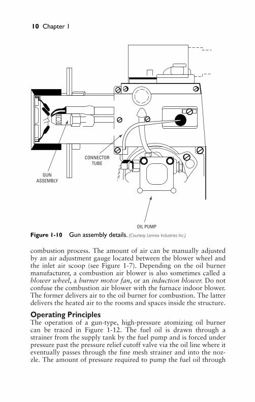
Gun AssemblyThe oil burner gun assembly consists of a burner nozzle, the elec-trodes, and a tube connecting the electrodes to the fuel pump (seeFigure 1-9). The burner nozzle changes the fuel oil into a form thatcan be burned in the combustion chamber. It accomplishes this byforcing the oil under pressure through a small hole at the end of thenozzle. The atomized fuel oil is ignited by spark from the electrodes.
6 Chapter 1
Figure 1-6 Typical gun-type oil burner (side view).(Courtesy Lennox Industries Inc.)
RETAININGCLIP
AIR TUBEASSY FORFB HEADS
FLANGEGASKET FLANGE
AIR TUBESCREWS HOLE PLUG ELECTRONIC IGNITION
TRANSFORMER
MAINHOUSING
ASSY
ESCUTCHEONPLATE
CONNECTORTUBE
ELECTRODEASSY
NOZZLE LINEELECTRODE HEAD
ASSY
NOZZLEADAPTER
HEADINSULATOR
FB-HEAD
GB039-1317G-P01[001-056].qxd 6/8/04 7:12 PM Page 6 Quark03 Quark03:Desktop Folder:repro:

Ignition TransformerA step-up ignition transformer located on top of the burner assem-bly produces the voltage used by the electrodes to ignite the fuel oil.This type of transformer is designed to increase the voltage of ahigh-voltage (110 VAC) circuit to the ultrahigh 14,000 voltsrequired to ignite the fuel oil.
Burner Motor and CouplingAs shown in Figure 1-5, the burner motor is located on the right sideof the oil burner assembly. The drive shaft of the burner motor isconnected to both the fuel pump and the combustion air blower by acoupling that functions as the drive shaft for both of these units. Aburner motor is also sometimes called an oil pump motor or a pumpmotor because it is connected to and drives the fuel (oil) pump.
Oil Burners 7
Figure 1-7 Typical gun-type oil burner (front view).(Courtesy Lennox Industries Inc.)
10
345678
BLOWERWHEEL
INLETAIR SCOOPCOMBUSTION AIR
MOTORCOUPLING
OIL PUMP
SPLINEDNUT
REAR ACCESSDOOR ASSY
VIEW PORT
REAR ACCESSDOOR GASKET
ELECTRONIC IGNITIONTRANSFORMER
BURNERCONTROL RESET
BUTTON
AIRADJUSTMENT
DIAL
GB039-1317G-P01[001-056].qxd 6/8/04 7:12 PM Page 7 Quark03 Quark03:Desktop Folder:repro:

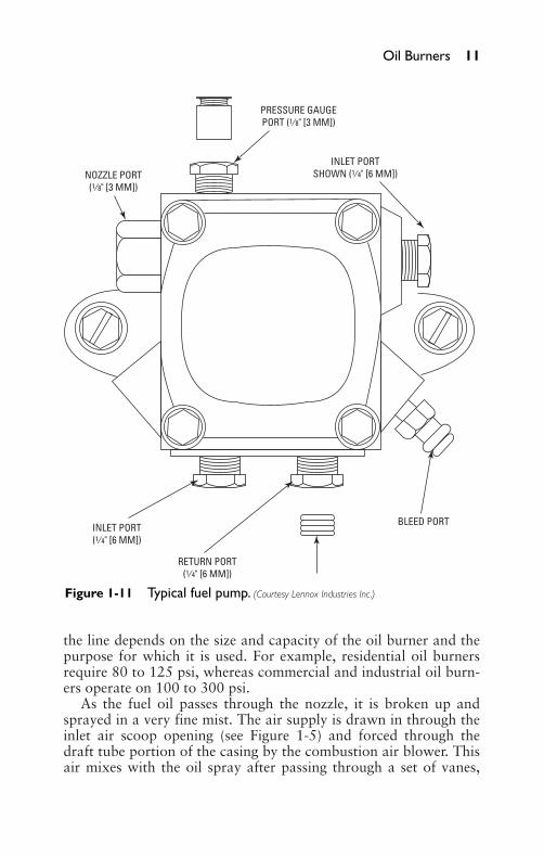
Fuel PumpThe fuel pump (also called an oil pump or a fuel unit) is used todraw fuel oil from the storage tank and deliver it under high pres-sure (100 to 140 psi) to the nozzle assembly (see Figure 1-11). It isdriven by the burner motor and coupling and is located on the leftside of the oil burner.
Combustion Air BlowerThe combustion air blower is also driven by the burner motor andcoupling. It is located between the burner motor and the fuel pump.Its function is to introduce the required amount of air for the
8 Chapter 1
BURNER CONTROL
CAD CELLFLAME DETECTORLOCATED INSIDEBURNER ASSEMBLY
FUEL PUMP
COMBUSTION AIRBLOWER ASSEMBLY
Figure 1-8 Locations of burner control and cadmium cell primarysafety control.
GB039-1317G-P01[001-056].qxd 6/8/04 7:12 PM Page 8 Quark03 Quark03:Desktop Folder:repro:

Oil Burners 9
Figure 1-9 Oil burner with transformer removed revealing the gunassembly. (Courtesy Wayne Home Equipment Co., Inc.)
NOZZLE ADAPTER
IGNITION POINTS BAFFLE PLATE
PORCELAIN INSULATORS
ELECTRODE SPRINGS
OIL-TIGHT FITTINGS
GB039-1317G-P01[001-056].qxd 6/8/04 7:12 PM Page 9 Quark03 Quark03:Desktop Folder:repro:
combustion process. The amount of air can be manually adjustedby an air adjustment gauge located between the blower wheel andthe inlet air scoop (see Figure 1-7). Depending on the oil burnermanufacturer, a combustion air blower is also sometimes called ablower wheel, a burner motor fan, or an induction blower. Do notconfuse the combustion air blower with the furnace indoor blower.The former delivers air to the oil burner for combustion. The latterdelivers the heated air to the rooms and spaces inside the structure.
Operating PrinciplesThe operation of a gun-type, high-pressure atomizing oil burnercan be traced in Figure 1-12. The fuel oil is drawn through astrainer from the supply tank by the fuel pump and is forced underpressure past the pressure relief cutoff valve via the oil line where iteventually passes through the fine mesh strainer and into the noz-zle. The amount of pressure required to pump the fuel oil through
10 Chapter 1
Figure 1-10 Gun assembly details. (Courtesy Lennox Industries Inc.)
GUNASSEMBLY
CONNECTORTUBE
OIL PUMP
GB039-1317G-P01[001-056].qxd 6/8/04 7:12 PM Page 10 Quark03 Quark03:Desktop Folder:repro:
the line depends on the size and capacity of the oil burner and thepurpose for which it is used. For example, residential oil burnersrequire 80 to 125 psi, whereas commercial and industrial oil burn-ers operate on 100 to 300 psi.
As the fuel oil passes through the nozzle, it is broken up andsprayed in a very fine mist. The air supply is drawn in through theinlet air scoop opening (see Figure 1-5) and forced through thedraft tube portion of the casing by the combustion air blower. Thisair mixes with the oil spray after passing through a set of vanes,
Oil Burners 11
Figure 1-11 Typical fuel pump. (Courtesy Lennox Industries Inc.)
RETURN PORT(1⁄4" [6 MM])
INLET PORTSHOWN (1⁄4" [6 MM])
PRESSURE GAUGEPORT (1⁄8" [3 MM])
NOZZLE PORT(1⁄8" [3 MM])
INLET PORT(1⁄4" [6 MM])
BLEED PORT
GB039-1317G-P01[001-056].qxd 6/8/04 7:12 PM Page 11 Quark03 Quark03:Desktop Folder:repro:
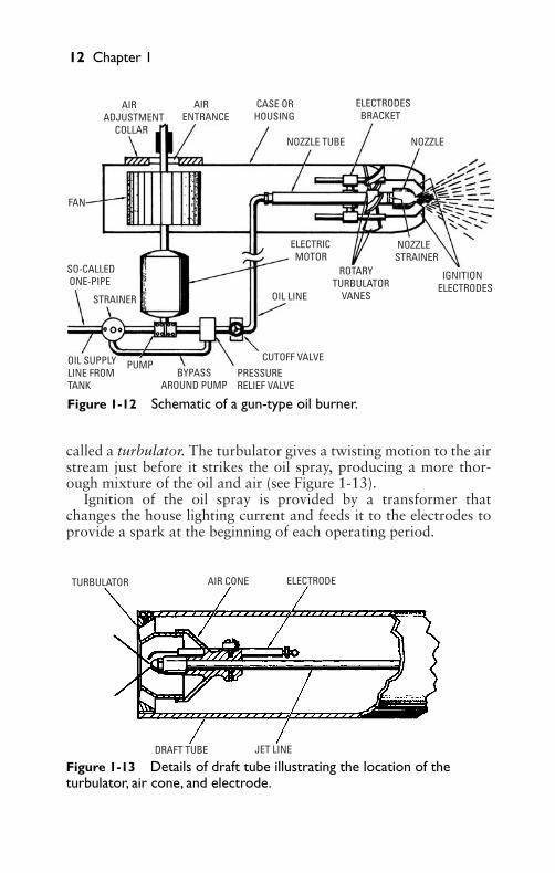
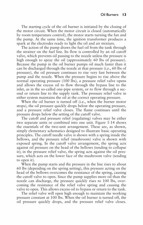
called a turbulator. The turbulator gives a twisting motion to the airstream just before it strikes the oil spray, producing a more thor-ough mixture of the oil and air (see Figure 1-13).
Ignition of the oil spray is provided by a transformer thatchanges the house lighting current and feeds it to the electrodes toprovide a spark at the beginning of each operating period.
12 Chapter 1
Figure 1-12 Schematic of a gun-type oil burner.
TURBULATOR AIR CONE ELECTRODE
JET LINEDRAFT TUBE
Figure 1-13 Details of draft tube illustrating the location of theturbulator, air cone, and electrode.
AIRADJUSTMENT COLLAR
FAN
SO-CALLED ONE-PIPE
STRAINER
OIL SUPPLYLINE FROMTANK
PUMP BYPASSAROUND PUMP
PRESSURERELIEF VALVE
CUTOFF VALVE
ELECTRIC MOTOR
OIL LINE
ROTARYTURBULATOR VANES
NOZZLESTRAINER
IGNITIONELECTRODES
AIRENTRANCE
CASE ORHOUSING
ELECTRODES BRACKET
NOZZLE TUBE NOZZLE
GB039-1317G-P01[001-056].qxd 6/8/04 7:12 PM Page 12 Quark03 Quark03:Desktop Folder:repro:
The starting cycle of the oil burner is initiated by the closing ofthe motor circuit. When the motor circuit is closed (automaticallyby room temperature control), the motor starts turning the fan andthe pump. At the same time, the ignition transformer produces aspark at the electrodes ready to light the oil and air mixture.
The action of the pump draws the fuel oil from the tank throughthe strainer on the fuel line. Its flow is controlled by an oil cutoffvalve, which prevents oil passing to the nozzle unless the pressure ishigh enough to spray the oil (approximately 60 lbs of pressure).Because the pump in the oil burner pumps oil much faster than itcan be discharged through the nozzle at that pressure (i.e., 60 lbs ofpressure), the oil pressure continues to rise very fast between thepump and the nozzle. When the pressure begins to rise above thenormal operating pressure (100 lbs), a pressure relief valve opensand allows the excess oil to flow through the bypass line to theinlet, as in the so-called one-pipe system, or to flow through a sec-ond or return line to the supply tank. The pressure relief valve ineither system maintains the oil at the correct operating pressure.
When the oil burner is turned off (i.e., when the burner motorstops), the oil pressure quickly drops below the operating pressure,and a pressure relief valve closes. The flame continues until thepressure drops below the setting of the cutoff valve.
The cutoff and pressure relief (regulating) valves may be eithertwo separate units or combined into one unit. Figure 1-14 showsthe essentials of the two-unit arrangement. These are, as shown,simply elementary schematics designed to illustrate basic operatingprinciples. The cutoff needle valve is shown with a spring inside thebellows, and the pressure relief (mushroom) valve is shown withexposed spring. In the cutoff valve arrangement, the spring actsagainst oil pressure on the head of the bellows (tending to collapseit); in the pressure relief valve, the spring acts against the oil pres-sure, which acts on the lower face of the mushroom valve (tendingto open it).
When the pump starts and the pressure in the line rises to about60 lbs (depending on the spring setting), this pressure acting on thehead of the bellows overcomes the resistance of the spring, causingthe cutoff valve to open. Since the pump supplies more oil than thenozzle can discharge, the pressure quickly rises to 100 lbs, over-coming the resistance of the relief valve spring and causing thevalve to open. This allows excess oil to bypass or return to the tank.
The relief valve will open high enough to maintain the workingpressure constant at 100 lbs. When the oil burner is turned off, theoil pressure quickly drops, and the pressure relief valve closes.
Oil Burners 13
GB039-1317G-P01[001-056].qxd 6/8/04 7:12 PM Page 13 Quark03 Quark03:Desktop Folder:repro:
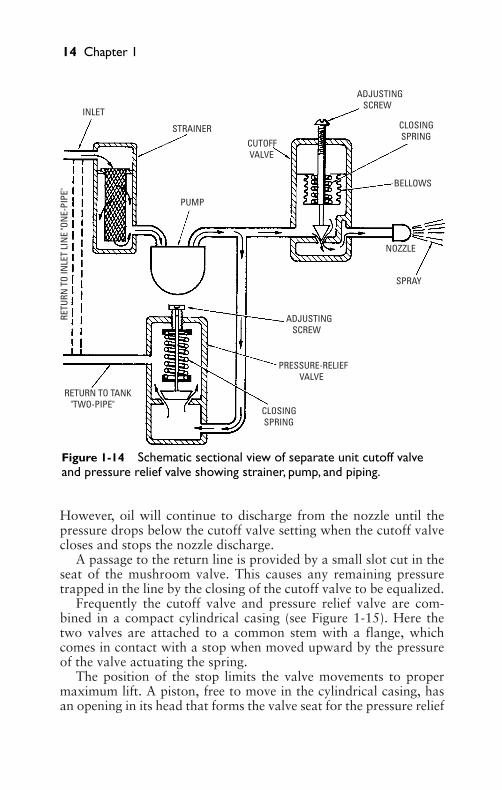
However, oil will continue to discharge from the nozzle until thepressure drops below the cutoff valve setting when the cutoff valvecloses and stops the nozzle discharge.
A passage to the return line is provided by a small slot cut in theseat of the mushroom valve. This causes any remaining pressuretrapped in the line by the closing of the cutoff valve to be equalized.
Frequently the cutoff valve and pressure relief valve are com-bined in a compact cylindrical casing (see Figure 1-15). Here thetwo valves are attached to a common stem with a flange, whichcomes in contact with a stop when moved upward by the pressureof the valve actuating the spring.
The position of the stop limits the valve movements to propermaximum lift. A piston, free to move in the cylindrical casing, hasan opening in its head that forms the valve seat for the pressure relief
14 Chapter 1
Figure 1-14 Schematic sectional view of separate unit cutoff valveand pressure relief valve showing strainer, pump, and piping.
INLET
STRAINER
CUTOFF VALVE
ADJUSTING SCREW
CLOSING SPRING
BELLOWS
NOZZLE
SPRAY
ADJUSTING SCREW
PRESSURE-RELIEF VALVE
CLOSING SPRING
RETURN TO TANK "TWO-PIPE"
PUMP
RETU
RN T
O IN
LET
LIN
E "O
NE-
PIPE
"
GB039-1317G-P01[001-056].qxd 6/8/04 7:12 PM Page 14 Quark03 Quark03:Desktop Folder:repro: