audio engineering society convention paper -...
TRANSCRIPT

Audio Engineering Society
Convention PaperPresented at the 125th Convention
2008 October 2–5 San Francisco, CA, USA
The papers at this Convention have been selected on the basis of a submitted abstract and extended precis that have been peerreviewed by at least two qualified anonymous reviewers. This convention paper has been reproduced from the author’s advancemanuscript, without editing, corrections, or consideration by the Review Board. The AES takes no responsibility for the contents.Additional papers may be obtained by sending request and remittance to Audio Engineering Society, 60 East 42nd Street, New York,New York 10165-2520, USA; also see www.aes.org. All rights reserved. Reproduction of this paper, or any portion thereof, is notpermitted without direct permission from the Journal of the Audio Engineering Society.
Is My Decoder Ambisonic?
Aaron J. Heller1, Richard Lee2, and Eric M. Benjamin3
1Artificial Intelligence Center, SRI International, Menlo Park, CA 94025, USA
2Pandit Littoral, Cooktown, Queensland 4895, AU
3Dolby Laboratories, San Francisco, CA 94044, USA
Correspondence should be addressed to Aaron J. Heller ([email protected])
ABSTRACT
In earlier papers, the present authors established the importance of various aspects of Ambisonic decoderdesign: a decoding matrix matched to the geometry of the loudspeaker array in use, phase-matched shelffilters, and near-field compensation. These are needed for accurate reproduction of spatial localiza-tion cues, such as interaural time difference (ITD), interaural level difference (ILD), and distance cues.Unfortunately, many listening tests of Ambisonic reproduction reported in the literature either omit thedetails of the decoding used or utilize suboptimal decoding.In this paper we review the acoustic and psychoacoustic criteria for Ambisonic reproduction, present amethodology and tools for “black box” testing to verify the performance of a candidate decoder, andpresent and discuss the results of this testing on some widely used decoders.
1. INTRODUCTIONThis paper is about testing Ambisonic decoders. The de-coder is the component of an Ambisonic reproductionsystem that derives the loudspeaker signals from the pro-gram signals. Unlike most other surround sound systemsin which each channel of a recording is intended to drivea single loudspeaker directly, an Ambisonic recordingcan be played back on a variety of speaker layouts, both2-D and 3-D, by using an appropriate decoder.
A key feature of Ambisonic theory is that it provides amathematical encapsulation of practically all known au-ditory localization models, except the pinna colorationand impulsive (high-frequency) interaural time delaymodels. These mathematical descriptions can be usedto prove theorems about surround sound recording andreproduction, predict what spatial information can andcannot be conveyed by a particular system, guide the de-sign of decoders, and as discussed in this paper, evaluate

Heller et al. Is My Decoder Ambisonic?
and validate implementations.
We assume that the reader is familiar with the basicworkings of surround sound in general and Ambisonicsin particular. Background material on these topics, aswell as sample Ambisonic recordings, can be found atvarious websites [1, 2].
Our interest in determining whether or not a given de-coder meets the criteria for Ambisonic reproduction ismotivated by practical considerations. When we firstconducted listening tests, we did what many do: ob-tained some recordings made with a Soundfield micro-phone, set up six loudspeakers in a hexagon, downloadeda decoder off the Internet, and listened with the defaultsettings. What we experienced was quite confusing —completely ambiguous localization and severe comb fil-tering artifacts from slight head movements. Over thenext few listening sessions, we tried other software de-coders and other settings with different but equally unsat-isfying results. Had we not had previous experience withgood Ambisonic reproduction, we might have stoppedthere and written off Ambisonics as yet another failedsurround sound technology.
Instead, we went to the benchmark of good Ambisonicplayback, what are known informally as Classic Am-bisonic Decoders — the hardware-based decoders de-signed by the original Ambisonics team [3] — and builtup an offline, file-to-file decoding workflow that mim-icked the processing performed by those decoders. Sinceeach step produced an intermediate file, we were ableto verify that our implementation was performing as ex-pected. The techniques described in this paper are a for-malization and extension of this verification process.
Finally, by using a playback program that provided syn-chronized playback of a number of files and rapid switch-ing among them, we were able to gain an understandingof the effects of each of the key components in an Am-bisonic decoder: a decoding matrix matched to the ge-ometry of the loudspeaker array in use, phase-matchedshelf filters, and near-field compensation (NFC). Theselistening tests demonstrated that using the correct de-coder results in dramatically improved performance [4,5].
A number of recent papers have reported on the resultsof Ambisonic listening tests that have used decoders thatare clearly faulty or employed incorrectly. As an exam-ple, in reference [6] the authors compare various spatial-ization techniques, including Ambisonics. The method-
ology used was well thought out, but unfortunately thesoftware used to decode the Ambisonic program mate-rial may not have been the most appropriate:
“The ‘in-phase’ ambisonic decoder was se-lected as it is recommended for larger roomsand listening areas, preventing anti-phase sig-nals to be fed to the loudspeaker opposite tothe sound source.”
Later in the paper, the authors conclude that Ambison-ics provides poor localization. However, given that thelistening tests were performed with single listeners us-ing a speaker array with 2-meter radius, the best (known)methodology for decoding would have been to performexact, or velocity decoding at low frequencies, energydecoding at middle and high frequencies and use near-field compensation.
Other software decoders have many adjustments, buttheir authors provide little or no guidance on appropri-ate settings for various playback situations, making itdifficult for a user to know if they are functioning cor-rectly without extensive listening tests. We have readmany accounts of “phasey”, “ambiguous”, or “unpleas-ant” Ambisonic reproduction that can be attributed to thisproblem. In particular, phasey reproduction will occurwhen exact velocity decoding is used at higher frequen-cies, where the wavelengths are smaller than the inter-eardistance.
The key point here is that it is not enough to simply spec-ify that an Ambisonic decoder was used; not all decodersor decoder philosophies perform in the same way. It isalso worth to noting that various workers in the field maynot want to design a decoder; they simply want to verifythat an existing one works properly and then use it.
Good engineering practice dictates that the behaviors ofthe individual components of a system under test be veri-fied so that its overall performance can be properly char-acterized. While the design criteria have been outlinedor implied in many papers, we have found no discussionof tools or methodologies to assess how well they havebeen met in a given implementation.
We confine the discussion in this paper to decoders suit-able for one or two listeners.1 In this paper we test only
1Design of decoders that work well over large areas is a distinctart and in general involves additional constraints that compromise theirperformance for small areas. [7]
AES 125th Convention, San Francisco, CA, USA, 2008 October 2–5Page 2 of 22

Heller et al. Is My Decoder Ambisonic?
horizontal, first-order Ambisonic decoders; however, theextensions for full 3-D reproduction (periphony) and ar-bitrary orders are straightforward.
There are a number of additional factors, any of whichcan have a large effect on the quality of playback butare beyond the scope of what is discussed here, suchas room acoustics, accuracy of speaker positioning andmatching, timing skew in multichannel D/A converters,and so forth. Simply due to the number of interconnec-tions, speakers, and amplifiers in a typical Ambisonicsplayback system, the odds of making a setup error aremuch higher than in the case of stereo and the faults moredifficult to diagnose than a channel reversal in stereo re-production.
Due to space limitations, we test just four decoders anda single speaker configuration, the
√3 : 1 rectangle. This
configuration was preferred over a square layout in pre-vious listening tests, as well as being easier to fit in mostdomestic rooms. We intend to populate our website [8]with more test results over time.
In summary, we are trying to decide if a given decoderand loudspeaker configuration meet the criteria for Am-bisonic reproduction as defined by Gerzon in [9].
A decoder or reproduction system for 360◦ sur-round sound is defined to be Ambisonic if, fora central listening position, it is designed suchthat
i) velocity and energy vector2 directions arethe same at least up to around 4 kHz, suchthat the reproduced azimuth θV = θE issubstantially unchanged with frequency,
ii) at low frequencies, say below around400 Hz, the magnitude of the velocityvector is near unity for all reproduced az-imuths,
iii) at mid/high frequencies, say betweenaround 700 Hz and 4 kHz, the energyvector magnitude, rE , is substantiallymaximised across as large a part of the360◦ sound stage as possible.
We feel that these are necessary, if perhaps not sufficient,conditions for good surround sound reproduction.
2Precise definitions of these are given in the next section.
2. REVIEW OF AMBISONIC CRITERIAGerzon defines two primitive models that are character-ized by the velocity localization vector (rV) and energylocalization vector (rE). These models encapsulate theprimary Interaural Time Difference (ITD) and InterauralLevel Difference (ILD) theories of auditory localization.The direction of each indicates the direction of the local-ization perception, and the magnitude indicates the qual-ity of the localization. In natural hearing, from a singlesource the magnitude of each is exactly 1 and the direc-tion is the direction to the source.
Ideally, both types of cue will be accurately recreated bya multispeaker playback environment and they will be inagreement with each other. In terms of Gerzon’s modelsthis means that rV and rE should agree in direction upto around 4 kHz; that below 400 Hz, the magnitude ofrV is near unity for all reproduced directions; and thatbetween 700 Hz and 4 kHz, |rE| is maximized over asmany reproduced directions as possible. |rE| achieves amaximum value of 1 for a single source and is alwaysless than 1 for multiple sources. Gerzon observes thata value less than 0.5 “gives rather poor image stability.”[10]
Following Gerzon [11], the magnitude and direction ofthe velocity vector, rV and rV, at the center of a speakerarray with n speakers is
rV rV = Re∑
ni=1 Giui
∑ni=1 Gi
(1)
whereas the magnitude and direction of the energy vec-tor, rE and rE are computed by
rE rE = ∑ni=1(GiGi
∗)ui
∑ni=1(GiGi
∗)(2)
where the Gi are the (possibly complex) gains from thesource to the i-th speaker, u is a unit vector in the direc-tion of the speaker, and Gi
∗ is the complex conjugate ofGi.
The main goal of the test protocol outlined in Sec. 3 isto recover the Gi’s used by the decoder under test for agiven source direction and speaker configuration. In thegeneral case, they vary with frequency; hence, Gi andGiGi
∗ can be thought of as the complex frequency andenergy responses of the decoder for a particular direction.
The remaining parameters are the imaginary parts of ve-locity localization vector
Im∑
ni=1 Giui
∑ni=1 Gi
(3)
AES 125th Convention, San Francisco, CA, USA, 2008 October 2–5Page 3 of 22

Heller et al. Is My Decoder Ambisonic?
which correspond to “phaseyness” arising from using fil-ters whose phase responses are not matched. The mostimportant part of this is the Y -component, the directionof the ear axis, over the frequency range 300 to 1500 Hz,and should be as close to zero as possible [11].
In general, optimizing the rV and rE vectors requires theuse of a different decoding matrix for each frequencyrange. This can be accomplished with shelf filters orband-splitting filters similar to those used in loudspeakercrossovers. In either case, it is imperative that the fil-ters are phase matched to preserve uniform frequency re-sponse over all directions.
Last, near-field compensation corrects for the reactivecomponent of the reproduced soundfield when the listen-ing position is within a few meters of the loudspeakers.
3. TEST PROTOCOLIt is not necessarily straightforward to determine whethera decoder is operating optimally simply by inspecting thesoftware or listening to the output. They must be tested inorder to verify that the desired characteristics have beenachieved.
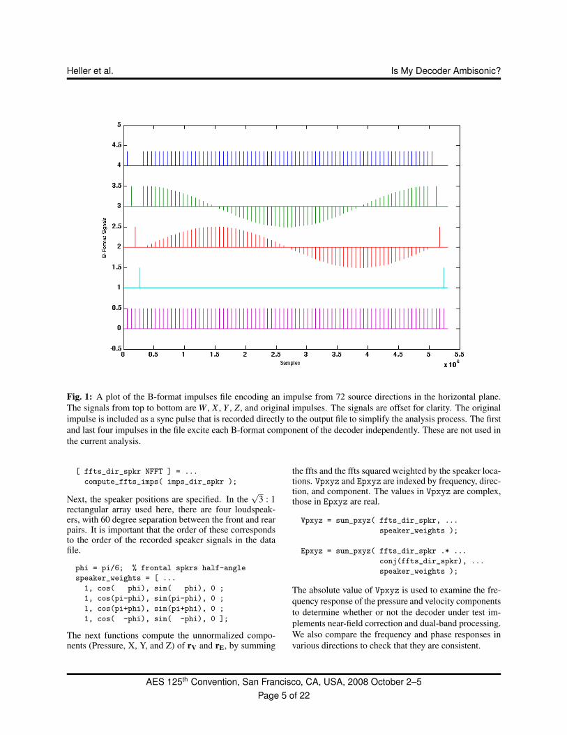
To do that, a test signal was created consisting of unit im-pulses at 216-sample intervals. This signal was encodedaccording to the B-format conventions (see Appendix 2)to create a series of unit impulses from varying sourcedirections. This test signal is the equivalent to the outputof a virtual soundfield microphone with a virtual sourcethat is moved from one angular position to the next. Theoriginal series of impulses is included on an additionalchannel in the test file to act as a sync signal to simplifythe later analysis. A plot of the test file is shown in Fig. 1.At 48 kHz sample frequency, the playing time of this fileis 109.2 seconds. 3
This file is then applied directly to the input of a softwaredecoder, or played out though a multichannel soundcardinto a hardware decoder, and the output recorded for sub-sequent analysis. In either case the intermediate outputof the testing process is a file containing the resultantloudspeaker feeds derived by the decoder for the partic-ular speaker configuration. The sync signal is recordeddirectly into the output file, without passing through thedecoder under test. A screen capture showing this pro-cess is shown in Fig. 2.
3Matlab code to generate this test file, along with the code discussedin Sec. 3.1 is available on our website [8].
In the current work, 72 horizontal directions are used andthe four loudspeaker feeds captured to the file, resultingin 288 impulse response (IR) measurements for each de-coder configuration tested.
To perform the analysis, the complex frequency and en-ergy responses are computed for each IR, yielding theGis needed to compute rV and rE according to Eqns. 1and 2. By examining these results, we can evaluate thedecoder against Gerzon’s criteria for Ambisonic repro-duction as well as our other criteria.
It is worth noting that a number of methods can be usedto measure the impulse response of a system. A surveyof these techniques can be found in Stan, et al. [13]. Anyof these techniques should work for this analysis. For ourcurrent purposes, we have selected the simplest one sinceit provides adequate signal-to-noise (S/N) ratio for directtesting of software decoders and removes the deconvolu-tion process as another potential source of errors. To testhardware decoders, more sophisticated IR measurementtechniques, such as MLS or Sine Sweep, are needed todeal with the lower S/N ratio and possibly higher distor-tion levels found in analog circuitry.
3.1. AnalysisWe have created a set of tools in Matlab to analyze therecorded impulse responses and produce various plots,which give us insight into the behavior of the decoders.All the Matlab code used in this paper is available on ourwebsite [8].The first function, read spkr imps, reads the speakerfeeds file, normalizes the range of the data to fullscale =1.0, extracts the sync pulses from the sync track, and thenuses them to extract the individual impulses. It returns a216×72×4 real-valued array, called imps dir spkr inthis example. The indices to each dimension representsample number, source direction in 5 degree increments,and speaker. It also returns the sample rate of the file, Fs.Optional return values are the raw samples and an arraycontaining the locations of the sync pulses.
[ imps_dir_spkr Fs ] = ...
read_spkr_imps( file );
The next function, compute ffts imps, takes theimps dir spkr array as input and computes the FFT ofeach impulse. This returns a complex valued array, withthe same indices as above, but with frequency instead ofsample number. It also returns the length of the FFT. Byslicing though this array along various dimensions, weobtain the data we need to compute the parameters ofinterest.
AES 125th Convention, San Francisco, CA, USA, 2008 October 2–5Page 4 of 22
Heller et al. Is My Decoder Ambisonic?
Fig. 1: A plot of the B-format impulses file encoding an impulse from 72 source directions in the horizontal plane.The signals from top to bottom are W , X , Y , Z, and original impulses. The signals are offset for clarity. The originalimpulse is included as a sync pulse that is recorded directly to the output file to simplify the analysis process. The firstand last four impulses in the file excite each B-format component of the decoder independently. These are not used inthe current analysis.
[ ffts_dir_spkr NFFT ] = ...
compute_ffts_imps( imps_dir_spkr );
Next, the speaker positions are specified. In the√
3 : 1rectangular array used here, there are four loudspeak-ers, with 60 degree separation between the front and rearpairs. It is important that the order of these correspondsto the order of the recorded speaker signals in the datafile.
phi = pi/6; % frontal spkrs half-angle
speaker_weights = [ ...
1, cos( phi), sin( phi), 0 ;
1, cos(pi-phi), sin(pi-phi), 0 ;
1, cos(pi+phi), sin(pi+phi), 0 ;
1, cos( -phi), sin( -phi), 0 ];
The next functions compute the unnormalized compo-nents (Pressure, X, Y, and Z) of rV and rE, by summing
the ffts and the ffts squared weighted by the speaker loca-tions. Vpxyz and Epxyz are indexed by frequency, direc-tion, and component. The values in Vpxyz are complex,those in Epxyz are real.
Vpxyz = sum_pxyz( ffts_dir_spkr, ...
speaker_weights );
Epxyz = sum_pxyz( ffts_dir_spkr .* ...
conj(ffts_dir_spkr), ...
speaker_weights );
The absolute value of Vpxyz is used to examine the fre-quency response of the pressure and velocity componentsto determine whether or not the decoder under test im-plements near-field correction and dual-band processing.We also compare the frequency and phase responses invarious directions to check that they are consistent.
AES 125th Convention, San Francisco, CA, USA, 2008 October 2–5Page 5 of 22

Heller et al. Is My Decoder Ambisonic?
Fig. 2: A screen capture of Plogue Bidule [12] being used as a test harness for a decoder available as a VST plug-in.This works for Windows and MacOSX, which also supports Apple Audio Unit plug-ins. A similar setup using Jackand Ecasound is used to test Linux-hosted decoders.
rV and rE are now computed by normalizing by the pres-sure component and converting to spherical coordinatesto yield the direction and magnitude. rVcart is com-plex. The real parts comprise rV. The imaginary parts,and in particular the one parallel to the Y -axis, indi-cate phaseyness due to use of filters that are not phasematched.
[ rVsph rVcart ] = r_from_pxyz( Vpxyz );
[ rEsph rEcart ] = r_from_pxyz( Epxyz );
At this point, polar plots of rV and rE are created atvarious frequencies and evaluated according to the Am-bisonic criteria discussed in Sec. 2.
4. KEY COMPONENTS OF AN AMBISONIC DE-CODERAll decoders must perform the fundamental function offorming suitable linear combinations of the B-format sig-nals for each loudspeaker in the array that reproduces thepressure and particle velocity at the central position inthe array. This set of linear combinations is called theexact or matching decoder matrix. It is also called thebasic solution of the speaker array or simply the velocitydecode. Regardless of what it is called, it is unique foreach loudspeaker array geometry.
In general, there are three types of loudspeaker arrays:
1. regular polygons and polyhedra, such as square,hexagon, cube, dodecahedron
2. irregular but with speakers in diametrically oppositepairs, such the
√3 : 1 rectangle tested here
3. general irregular arrays, such as an ITU 5.1 array
In all cases the number of loudspeakers must exceed thenumber of B-format signals.
A method for deriving the decoder matrix for the firsttwo types is given in Appendix 1.4 In the case of regulararrays, this reduces to the result that the decoding and en-coding matrices are identical, with the speaker positionssubstituted for the source positions. The single most per-vasive error in Ambisonic decoder design and use is as-suming that also holds for irregular arrays. Sec. 5.3 dis-cusses the effect of this error. In our experience, mostsoftware Ambisonic decoders that can be downloadedare of this type.
The exact decoder matrix recreates the pressure and ve-locity at the central position under the assumption that
4Methods for the third type remain an area of open research [14].
AES 125th Convention, San Francisco, CA, USA, 2008 October 2–5Page 6 of 22

Heller et al. Is My Decoder Ambisonic?
the wavefronts are planar, i.e., sources and loudspeakersat an infinite distance. Sources and loudspeakers at finitedistances produce wavefronts with a “reactive” (or imag-inary) component, which is perpendicular to the direc-tion of propagation, in addition to the “real” component,which is parallel to the direction of propagation. Thisresults in the well-known bass-boosting proximity effectin directional microphones. It is important to understandthat this is an actual physical effect, not a design flaw inthe microphone or loudspeaker.5 For point sources, thefrequency at which the reactive and real components areequal is given by [15]
f =c
2πd(4)
where c is the speed of sound and d is the distance fromthe loudspeaker.
In terms of the velocity localization vector, this makesrV > 1 at low frequencies, which has the effect of widen-ing the source images. This artifact is most apparent inrecordings of string trios and quartets, where the cellosounds as if it is somewhat larger and closer than theother instruments. To compensate for this, a single-polehigh-pass filter is applied to the velocity signals in the de-coder. We call this near-field compensation. The designof this filter is covered in Appendix 1.
This exact reproduction of acoustic pressure and velocityis equivalent to the condition rV = 1 in Gerzon’s veloc-ity localization model. In theory that happens at onlya single point in space; however, in practice, it is goodenough up to roughly one-half wavelength from the cen-tral position. If we desire reconstruction over an area of0.5-meter, the exact decoder matrix can be used up toabout 300 Hz and corresponds to the frequency regimeof ITD-based auditory localization. If it is used beyondthat frequency, comb filter artifacts and in-head localiza-tion effects will be experienced by the listener. This isprobably the second most common error in Ambisonicreproduction.
At higher frequencies, say 700 to 4000 Hz, ILD-basedauditory localization models are appropriate, which Ger-zon encapsulates in the energy localization vector, rE.
5The implication for B-format signal encoding is that the X, Y, andZ signals must have a low-frequency boost and phase shift relative tothe W signal, the amount of which is a function of the source distance.For natural acoustic sources, a properly aligned Soundfield-type mi-crophone does this by virtue of accurate transduction of the incidentwavefronts, and thereby encodes distance. For synthetic sources, thismust be included in the encoding equations. Further discussion of thisis in Appendix 2.
The one parameter that can be changed in the exact solu-tion without changing the direction of the velocity local-ization vector, rV, is the velocity-to-pressure ratio (i.e,the gain of X, Y, and Z vs. W), usually denoted by k.6
Writing the magnitude of the energy localization vector,rE , as a function of k, for any regular 2-D polygonal arraywith at least four speakers, we get
rE(k) =2k
2k2 +1(5)
which attains its maximum value at k =√
22 ≈ 0.7071 ≈
−3.01 dB.7 In the case of a regular 3-D polyhedral array,with at least six speakers, we get
rE(k) =2k
3k2 +1(6)
which attains its maximum value at k =√
33 ≈ 0.5774 ≈
−4.77 dB. Fig. 3 shows graphs of these equations. Solu-tions with these values of k are often called “Max-rE” or“energy decodes.”
Next we must apportion the total between boost for pres-sure and cut for velocity in such a way that the over-all loudness and balance between low and high frequen-cies is maintained. One approach is preserving the root-mean-square (RMS) level. In the 2-D case
W 2 +X2 +Y 2 = 3 at both LF & HF (7)
XW
=YW
=√
22
at HF only (8)
solving for the HF gains
W =
√32≈+1.76 dB (9)
X = Y =
√34≈−1.25 dB (10)
In the 3-D case
W 2 +X2 +Y 2 +Z2 = 4 at both LF & HF (11)
XW
=YW
=ZW
=√
33
at HF only (12)
solving for the HF gains
W =√
2≈+3.01 dB (13)
X = Y = Z =
√23≈−1.76 dB (14)
6k is equivalent to the inverse of the acoustic impedance.7found by setting the derivative with respect to k equal to zero and
finding the roots
AES 125th Convention, San Francisco, CA, USA, 2008 October 2–5Page 7 of 22

Heller et al. Is My Decoder Ambisonic?
Fig. 3: Plots of rE as a function of the velocity-to-pressure ratio k. The top curve shows the 2-D case, thebottom curve shows the 3-D case. The maximum valuesare
√2
2 and√
33 , respectively.
For irregular diametric arrays (“type 2”), the magnitudeof rE varies in direct proportion to the angular densityof the loudspeakers in a given direction, but for first-order Ambisonics the average value cannot exceed
√2
2
for horizontal arrays and√
33 for 3-D arrays. Gerzon
notes that√
33 is “perilously close to being unsatisfactory”
[10]. However, in most periphonic (with height) systems,practical and domestic considerations often dictate thatthere will be more speakers in near horizontal than ver-tical directions. Localization is better in directions withmore speakers — hence, our preference for a rectanglehorizontal array over a square for predominantly frontalsource material. However, Ambisonic systems have aclear advantage over other surround systems in that am-bient/diffuse sounds are still perceived realistically evenfrom directions with “poor localization.”
A physical interpretation of the energy decode is that fora square array, a source directly ahead (azimuth zero),is reproduced with equal gain in the two front speak-ers and with zero gain in the two rear speakers. Thatis, the virtual microphone pattern formed by the gainsfrom a source to the speakers is a near-supercardoid, withthe two nulls at the angular locations of the rear speak-ers. The same is true in 3-D of a cube array; a frontalsound with azimuth and elevation zero, is reproducedwith equal gain in the front speakers and with zero gain
in the rear speakers.
This suggests that for optimal reproduction two decodingmatrices are needed, one for low frequencies with k = 1and another for high frequencies, with k =
√2
2 or√
33 for
the 2-D and 3-D cases, respectively. Classic AmbisonicDecoders used phase-matched shelf filters to “morph”the exact solution into the energy solution. A more flexi-ble strategy, first suggested by Barton [9], is to split eachB-format signal into two bands so that two independentsolutions can be used. We call this a dual-band decoder.It requires the use of phase-matched band-splitting filterssimilar to those used in loudspeaker crossover networks.The design of such filters is discussed in Appendix 1.
In summary, all the key components
• decoding matrices matched to the speaker array ge-ometry
• near-field compensation
• frequency-frequency-dependent gains (shelf filtersor a dual-band) optimizing for ITD and ILD cuesusing phase-matched filters
are needed to satisfy various localization mechanisms. Itis this compensation for important psychoacoustic phe-nomena by simple means that makes a decoder Am-bisonic.
Anecdotal evidence suggests that using shelf or band-splitting filters with small phase-matching errors is bet-ter than omitting frequency-dependent processing all to-gether. This remains to be confirmed with formal listen-ing tests, however. Finally, if one must use a decoderwithout frequency-dependent processing, the best resultwill be obtained using the energy-optimized values of kfor all frequencies [4].
5. EXAMPLESWe review general classes of decoders and discuss theresults of testing on four samples. Two perform well andtwo do not perform well for the given speaker configura-tion, the
√3 : 1 rectangle.
5.1. Types of DecodersBeyond the issues of operating system, audio and userinterfaces, the main distinguishing attributes of decodersare which of the three necessary components discussedin Sec. 4 are implemented and how the decoding matrixis specified to the decoder.
AES 125th Convention, San Francisco, CA, USA, 2008 October 2–5Page 8 of 22
Heller et al. Is My Decoder Ambisonic?
Some decoders provide presets such as square, rectangle,pentagon, hexagon, cube, dodecahedron, and so forth.With others the angular position of the speaker is en-tered along with the directivity of a virtual microphoneor gains of the various orders of spherical harmonics. Inthe third type, the decoding matrix is specified directly.
5.2. Decoder 1Decoder 1 is Adriaensen’s AmbDec [16]. Version 0.2.0was tested on a dual AMD Athlon machine running Fe-dora Core 8 and the Planet CCRMA distribution of audiosoftware [17]. It has provisions for near-field compensa-tion, dual-band processing, and a number of other fea-tures. The decoding matrices are specified directly in theconfiguration file. The distribution contains presets filesfor common loudspeaker arrays, but does not include the√
3 : 1 array. It was tested with decoding matrices de-rived by the procedure outlined in Appendix 1. Distancewas set to 2.0 meters and dual-band decoding was turnedon with 380 Hz crossover.
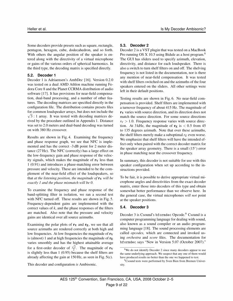
Results are shown in Fig. 4. Examining the frequencyand phase response graph, we see that NFC is imple-mented and has the correct -3 dB point for 2 meter dis-tance (27 Hz). The NFC (correctly) has a large effect onthe low-frequency gain and phase response of the veloc-ity signals, which makes the magnitude of rV less than1 (0.91) and introduces a phase-matching error betweenpressure and velocity. These are intended to be the com-plement of the near-field effect of the loudspeakers, sothat at the listening position, the magnitude of rV will beexactly 1 and the phase mismatch will be 0.
To examine the frequency and phase response of theband-splitting filter in isolation, we ran a second testwith NFC turned off. These results are shown in Fig. 5.Frequency-dependent gains are implemented with thecorrect values of k, and the phase responses of the filtersare matched. Also note that the pressure and velocitygains are identical over all source azimuths.
Examining the polar plots of rV and rE, we see that allsource azimuths are rendered correctly at both high andlow frequencies. At low frequencies the magnitude of rVis (almost) 1 and at high frequencies the magnitude of rEvaries smoothly and has the highest attainable averagefor a first-order decoder of
√2
2 . The magnitude of rVis slightly less than 1 (0.95) because the shelf filters arealready affecting the gain at 150 Hz, as seen in Fig. 5(c).
This decoder and configuration is Ambisonic.
5.3. Decoder 2Decoder 2 is a VST plugin that was tested on a MacBookPro running OS X 10.5 using Bidule as a host program.8
The GUI has sliders used to specify azimuth, elevation,directivity, and distance for each loudspeaker. There isalso a switch to turn shelf filters on and off. The shelvingfrequency is not listed in the documentation, nor is thereany mention of near-field compensation. It was testedwith shelf filters switched on and the azimuths of the fourspeakers entered on the sliders. All other settings wereleft in their default positions.
Testing results are shown in Fig. 6. No near-field com-pensation is provided. Shelf filters are implemented witha turnover frequency of about 415 Hz. The magnitude ofrV varies with source direction, and its direction does notmatch the source direction. For some source directionsrV > 1.0. Frequency response varies with source direc-tion. At 3 kHz, the magnitude of rE is < 0.5 from 45to 135 degrees azimuth. Note that over these azimuths,the shelf filters merely make a suboptimal rE even worse.We emphasize that shelf filters will have the intended ef-fect only when paired with the correct decoder matrix forthe speaker array geometry. There is a small (15◦) errorin phase matching near the crossover frequency.
In summary, this decoder is not suitable for use with thisspeaker configuration when set up according to the in-structions provided.
To be fair, it is possible to derive appropriate virtual mi-crophone angles and directivities from the exact decodermatrix, enter those into decoders of this type and obtainsomewhat better performance than we observe here. Inthe general case, the virtual microphones will not pointat the speaker positions.
5.4. Decoder 3
Decoder 3 is Csound’s bformdec Opcode.9 Csound is acomputer programming language for dealing with sound,also known as a sound compiler or an audio program-ming language [18]. The sound processing elements arecalled opcodes, which are connected and invoked us-ing orchestra and score files. The documentation forbformdec says “New in Version 5.07 (October 2007).”
8We do not identify Decoder 2 since many decoders appear to usethe same underlying approach. We suspect that any one of them wouldhave produced results no better than the one we happened to test.
9Csound tests were performed by Sven Bien from Bremen Univer-sity.
AES 125th Convention, San Francisco, CA, USA, 2008 October 2–5Page 9 of 22

Heller et al. Is My Decoder Ambisonic?
(a) rV and rE measured at 150 Hz (b) rV and rE measured at 3 kHz
(c) frequency and phase response
Fig. 4: AmbDec with configuration derived by the procedure given in Appendix 1. This is a very good result. (a)and (b) show rV and rE at 150 Hz and 3 kHz. Source directions are correct and matched. The magnitude of rV isuniform in all directions and rE at 3 kHz attains an average value of
√2
2 . (c) shows that NFC and dual-band processingis implemented. The next figure shows the same configuration with NFC switched off so that frequency and phaseresponse can be examined in isolation.
AES 125th Convention, San Francisco, CA, USA, 2008 October 2–5Page 10 of 22

Heller et al. Is My Decoder Ambisonic?
(a) rV and rE measured at 150 Hz (b) rV and rE measured at 3 kHz
(c) frequency and phase response
(d) phase mismatch between pressure and velocity
Fig. 5: AmbDec with NFC switched off. Only three lines are seen in (c) because the pressure and velocity phaseresponses are identical.
AES 125th Convention, San Francisco, CA, USA, 2008 October 2–5Page 11 of 22

Heller et al. Is My Decoder Ambisonic?
(a) rV and rE measured at 150 Hz (b) rV and rE measured at 3 kHz
(c) frequency and phase response for a 0◦ azimuth source (d) frequency and phase response for a 90◦ azimuth source
(e) phase mismatch between pressure and velocity
Fig. 6: Decoder 2
AES 125th Convention, San Francisco, CA, USA, 2008 October 2–5Page 12 of 22
Heller et al. Is My Decoder Ambisonic?
This opcode does not have provision for the rectangu-lar configuration we are using; however, it is still usefulto include this test as an example of a decoder that is inwidespread use.
The test was conducted with the following orchestra file:
sr = 48000
kr = 4800
ksmps = 10
nchnls = 5
instr 1
a1 soundin "bf-1-sync.wav"
aw soundin "bf-2-w.wav"
ax soundin "bf-3-x.wav"
ay soundin "bf-4-y.wav"
az soundin "bf-5-z.wav"
a2, a3, a4, a5 bformdec 2, aw, ax, ay, az
outc a1, a2, a3, a4, a5
endin
Test results are shown in Fig. 7.
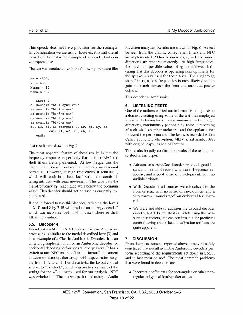
The most apparent feature of these results is that thefrequency response is perfectly flat; neither NFC norshelf filters are implemented. At low frequencies themagnitude of rV is 1 and source directions are renderedcorrectly. However, at high frequencies it remains 1,which will result in in-head localization and comb fil-tering artifacts with head movement. This also puts thehigh-frequency rE magnitude well below the optimumvalue. This decoder should not be used as currently im-plemented.
If one is forced to use this decoder, reducing the levelsof X , Y , and Z by 3 dB will produce an “energy decode,”which was recommended in [4] in cases where no shelffilters are available.
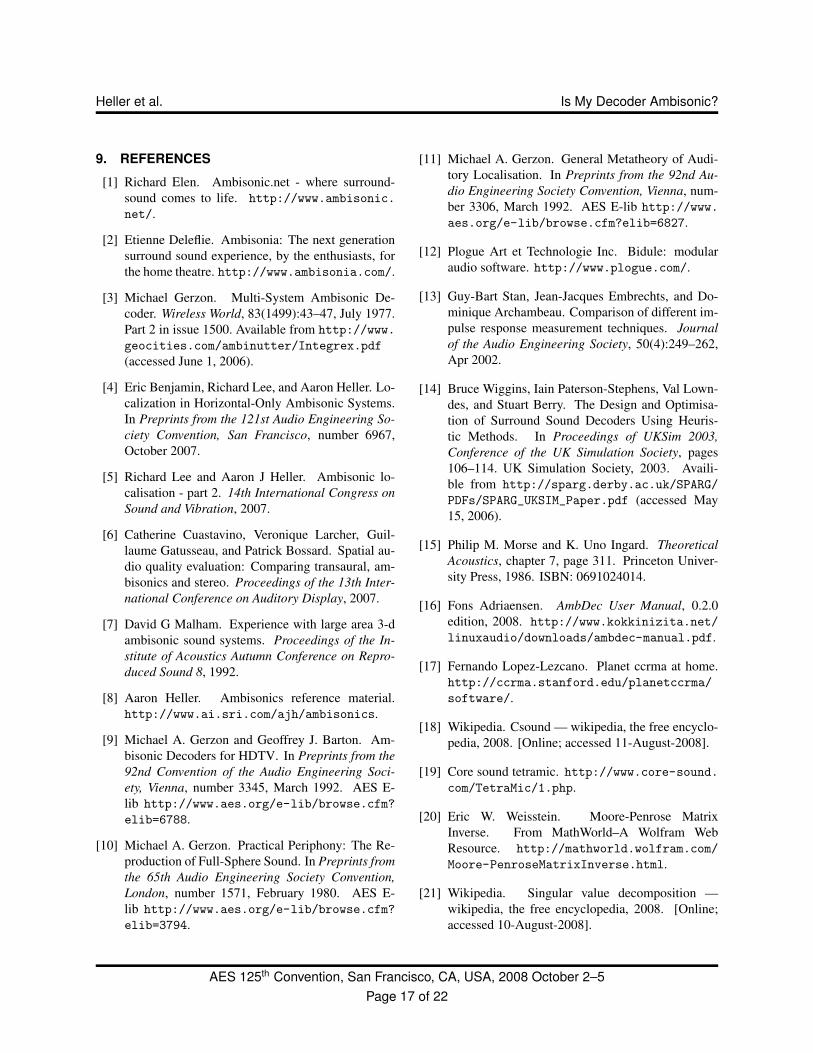
5.5. Decoder 4Decoder 4 is a Mimim AD-10 decoder whose Ambisonicprocessing is similar to the model described here [3] andis an example of a Classic Ambisonic Decoder. It is anall-analog implementation of an Ambisonic decoder forhorizontal decoding to four or six loudspeakers. It has aswitch to turn NFC on and off and a “layout” adjustmentto accommodate speaker arrays with aspect ratios rang-ing from 1 : 2 to 2 : 1. For these tests, the layout controlwas set to “3 o’clock”, which was our best estimate of thesetting for the
√3 : 1 array used for our analysis. NFC
was switched on. The test was performed using an Audio
Precision analyzer. Results are shown in Fig. 8. As canbe seen from the graphs, correct shelf filters and NFCare implemented. At low frequencies, rV = 1 and sourcedirections are rendered correctly. At high frequencies,the maximum possible values of rE are achieved, indi-cating that this decoder is operating near optimally forthe speaker array used for these tests. The slight “eggshape” in rE at low frequencies is most likely due to again mismatch between the front and rear loudspeakeroutputs.
This decoder is Ambisonic.
6. LISTENING TESTSOne of the authors carried out informal listening tests ina domestic setting using some of the test files employedin earlier listening tests: voice announcements in eightdirections, continuously panned pink noise, a recordingof a classical chamber orchestra, and the applause thatfollowed the performance. The last was recorded with aCalrec Soundfield Microphone MkIV, serial number 099,with original capsules and calibration.
The results broadly confirm the results of the testing de-scribed in this paper.
• Adriaensen’s AmbDec decoder provided good lo-calization in all directions, uniform frequency re-sponse, and a good sense of envelopment, with noaudible artifacts.
• With Decoder 2 all sources were localized to thefront or rear, with no sense of envelopment and avery narrow “sound stage” on orchestral test mate-rial.
• We were not able to audition the Csound decoderdirectly, but did simulate it in Bidule using the mea-sured parameters, and can confirm that the predictedcomb-filtering and in-head localization artifacts arequite apparent.
7. DISCUSSIONFrom the measurements reported above, it may be safelyconcluded that not all available Ambisonic decoders per-form according to the requirements set down in Sec. 2,and in fact most do not! The most common problemsthat were found in decoders are
• Incorrect coefficients for rectangular or other non-regular polygonal loudspeaker arrays
AES 125th Convention, San Francisco, CA, USA, 2008 October 2–5Page 13 of 22

Heller et al. Is My Decoder Ambisonic?
(a) rV and rE measured at 150 Hz (b) rV and rE measured at 3 kHz
(c) frequency and phase response for all source azimuths
Fig. 7: Decoder 3 Csound’s bformdec Opcode. Only two of the four lines are visible in (c) because the pressure andvelocity responses are identical.
AES 125th Convention, San Francisco, CA, USA, 2008 October 2–5Page 14 of 22

Heller et al. Is My Decoder Ambisonic?
(a) rV and rE measured at 150 Hz (b) rV and rE measured at 3 kHz
(c) frequency response with and without NFC (d) phase mismatch between pressure and velocity
Fig. 8: Decoder 4 Minim Analog Ambisonic Decoder.
AES 125th Convention, San Francisco, CA, USA, 2008 October 2–5Page 15 of 22

Heller et al. Is My Decoder Ambisonic?
• Lack of dual-band decoding
• Lack of near-field compensation
These omissions or errors cause the audio reproductionto suffer from poor localization behavior, phasiness, andother artifacts.
The regular polygon dilemmaGerzon described, in General Metatheory, a “naıve de-coder for a regular polygon loudspeaker Layout,” withthe following form:
W+Xcosθ +Y sinθ (15)
for which he proved that “the Makita and Energy vectorlocalizations coincide, and the energy vector magnitude,rE , cannot exceed
√2
2 . Unfortunately, that statement istrue only for the case of regular polygons, and follow-ing this form for nonregular polygons gives an incorrectresult. Specifically, if a regular array is narrowed, thenthe naıve decoder gives values for the coefficients thatare larger for X and smaller for Y, relative to the regularpolygon. But intuition tells us that narrowing the arraywould require less X and more Y to achieve the samelocalization vectors.
The correct decoder for the rectangle case is
W± X√2cosφ
± Y√2sinφ
(16)
where 2φ is the angle subtended by the front two loud-speakers.
It may be argued, and in fact we do argue, that the rect-angle decoder (and its 3-D extension, the bi-rectangle)is the single most important case for actual applicationsin reproduction of first-order Ambisonic recordings. Thereason for this importance is that rectangular arrays fitbetter into ordinary rooms, and in addition that they givea needed improvement in mid/high-frequency localiza-tion toward the front and back when the correct decoderis used.
Many of the available software Ambisonic decoders donot implement dual-band decoding, presumably becauseof lack of knowledge about how to design IIR filters.When dual-band decoding is implemented, it frequentlyis found to utilize shelf filters that are not phase matchedbetween the filter for W and the filters for X/Y/Z. Sincethat phase mismatch occurs only in the frequency range
around the transition frequency (see Fig. 6(e)), it is dif-ficult to evaluate the seriousness of the error. Clearly,any errors will be program dependent, depending on thespectral density in that particular frequency range. How-ever, it is relatively easy to do it correctly and it shouldbe done correctly. See Appendix 1.
Previous listening tests by the authors of this paper, andinformal listening tests done during the writing of thepresent paper, have shown the importance of all the fea-tures of an Ambisonic decoder. The use of Ambisonicdecoders that are inappropriate to the venue, or have in-correct decoding coefficients, or lack the important fea-tures of dual-band decoding and NFC will give resultsthat are inferior to what would be obtained with a correctAmbisonic decoder and which will prejudice the resultsof comparative listening tests.
In this paper, we have made every effort to “tell it all” asclearly and plainly as we can without oversimplification,and back that up with examples, test files, and samplecode that can be downloaded and used. We hope thatresearchers conducting experiments in audio localizationwill adopt these or similar techniques to validate their ex-perimental setups and that decoder writers will now havenecessary knowledge and tools to write better decoders.
A decade ago, lack of program material (B-formatrecordings) was the biggest problem with Ambisonics.Now that downloads of B-format recordings [2], rela-tively low-cost B-format microphones [19], and pocket-sized multichannel digital audio recorders are available,suitable program material is somewhat more plentiful.
The next hurdle is the creation of easy-to-use play-back software that runs on popular computing platforms,about which we can say: These are Ambisonic.
8. ACKNOWLEDGMENTSThe authors thank Sven Bien from Bremen Universityand his advisor Jorn Loviscach at Hochschule Bremen,University of Applied Sciences, for help with Csound,and in particular Sven for running the tests under verytight deadline constraints. We also thank the participantsin the sursound email discussion group for their encour-agement and comments, Don Drewecki for providing asteady flow of top-notch B-format concert recordings forour listening tests, and Jim Mastracco for many hours ofstimulating discussion on microphones and acoustics.
AES 125th Convention, San Francisco, CA, USA, 2008 October 2–5Page 16 of 22
Heller et al. Is My Decoder Ambisonic?
9. REFERENCES
[1] Richard Elen. Ambisonic.net - where surround-sound comes to life. http://www.ambisonic.net/.
[2] Etienne Deleflie. Ambisonia: The next generationsurround sound experience, by the enthusiasts, forthe home theatre. http://www.ambisonia.com/.
[3] Michael Gerzon. Multi-System Ambisonic De-coder. Wireless World, 83(1499):43–47, July 1977.Part 2 in issue 1500. Available from http://www.geocities.com/ambinutter/Integrex.pdf(accessed June 1, 2006).
[4] Eric Benjamin, Richard Lee, and Aaron Heller. Lo-calization in Horizontal-Only Ambisonic Systems.In Preprints from the 121st Audio Engineering So-ciety Convention, San Francisco, number 6967,October 2007.
[5] Richard Lee and Aaron J Heller. Ambisonic lo-calisation - part 2. 14th International Congress onSound and Vibration, 2007.
[6] Catherine Cuastavino, Veronique Larcher, Guil-laume Gatusseau, and Patrick Bossard. Spatial au-dio quality evaluation: Comparing transaural, am-bisonics and stereo. Proceedings of the 13th Inter-national Conference on Auditory Display, 2007.
[7] David G Malham. Experience with large area 3-dambisonic sound systems. Proceedings of the In-stitute of Acoustics Autumn Conference on Repro-duced Sound 8, 1992.
[8] Aaron Heller. Ambisonics reference material.http://www.ai.sri.com/ajh/ambisonics.
[9] Michael A. Gerzon and Geoffrey J. Barton. Am-bisonic Decoders for HDTV. In Preprints from the92nd Convention of the Audio Engineering Soci-ety, Vienna, number 3345, March 1992. AES E-lib http://www.aes.org/e-lib/browse.cfm?elib=6788.
[10] Michael A. Gerzon. Practical Periphony: The Re-production of Full-Sphere Sound. In Preprints fromthe 65th Audio Engineering Society Convention,London, number 1571, February 1980. AES E-lib http://www.aes.org/e-lib/browse.cfm?elib=3794.
[11] Michael A. Gerzon. General Metatheory of Audi-tory Localisation. In Preprints from the 92nd Au-dio Engineering Society Convention, Vienna, num-ber 3306, March 1992. AES E-lib http://www.aes.org/e-lib/browse.cfm?elib=6827.
[12] Plogue Art et Technologie Inc. Bidule: modularaudio software. http://www.plogue.com/.
[13] Guy-Bart Stan, Jean-Jacques Embrechts, and Do-minique Archambeau. Comparison of different im-pulse response measurement techniques. Journalof the Audio Engineering Society, 50(4):249–262,Apr 2002.
[14] Bruce Wiggins, Iain Paterson-Stephens, Val Lown-des, and Stuart Berry. The Design and Optimisa-tion of Surround Sound Decoders Using Heuris-tic Methods. In Proceedings of UKSim 2003,Conference of the UK Simulation Society, pages106–114. UK Simulation Society, 2003. Availi-ble from http://sparg.derby.ac.uk/SPARG/PDFs/SPARG_UKSIM_Paper.pdf (accessed May15, 2006).
[15] Philip M. Morse and K. Uno Ingard. TheoreticalAcoustics, chapter 7, page 311. Princeton Univer-sity Press, 1986. ISBN: 0691024014.
[16] Fons Adriaensen. AmbDec User Manual, 0.2.0edition, 2008. http://www.kokkinizita.net/linuxaudio/downloads/ambdec-manual.pdf.
[17] Fernando Lopez-Lezcano. Planet ccrma at home.http://ccrma.stanford.edu/planetccrma/software/.
[18] Wikipedia. Csound — wikipedia, the free encyclo-pedia, 2008. [Online; accessed 11-August-2008].
[19] Core sound tetramic. http://www.core-sound.com/TetraMic/1.php.
[20] Eric W. Weisstein. Moore-Penrose MatrixInverse. From MathWorld–A Wolfram WebResource. http://mathworld.wolfram.com/Moore-PenroseMatrixInverse.html.
[21] Wikipedia. Singular value decomposition —wikipedia, the free encyclopedia, 2008. [Online;accessed 10-August-2008].
AES 125th Convention, San Francisco, CA, USA, 2008 October 2–5Page 17 of 22
Heller et al. Is My Decoder Ambisonic?
[22] Wikipedia. Digital biquad filter — wikipedia, thefree encyclopedia, 2008. [Online; accessed 11-August-2008].
[23] Leo Beranek. Acoustic Measurements, pages 56–64. John Wiley, New York, 1949.
[24] Philip Cotterel. On the Theory of the Second-OrderSoundfield Microphone. PhD thesis, Dept. of Cy-bernetics. Reading University, Febuary 2002.
[25] Jerome Daniel. Spatial sound encoding includingnear field effect: Introducing distance coding filtersand a viable, new ambisonic format. Preprints 23rdAES International Conference, Copenhagen, 2003.
APPENDICES
1. DECODER DESIGNWe present some “cookbook” procedures for the designof the key decoder components, along with some digres-sions into the underlying theory and mathematics. Ex-amples and implementations of all three can be found onthe authors’ website [8].
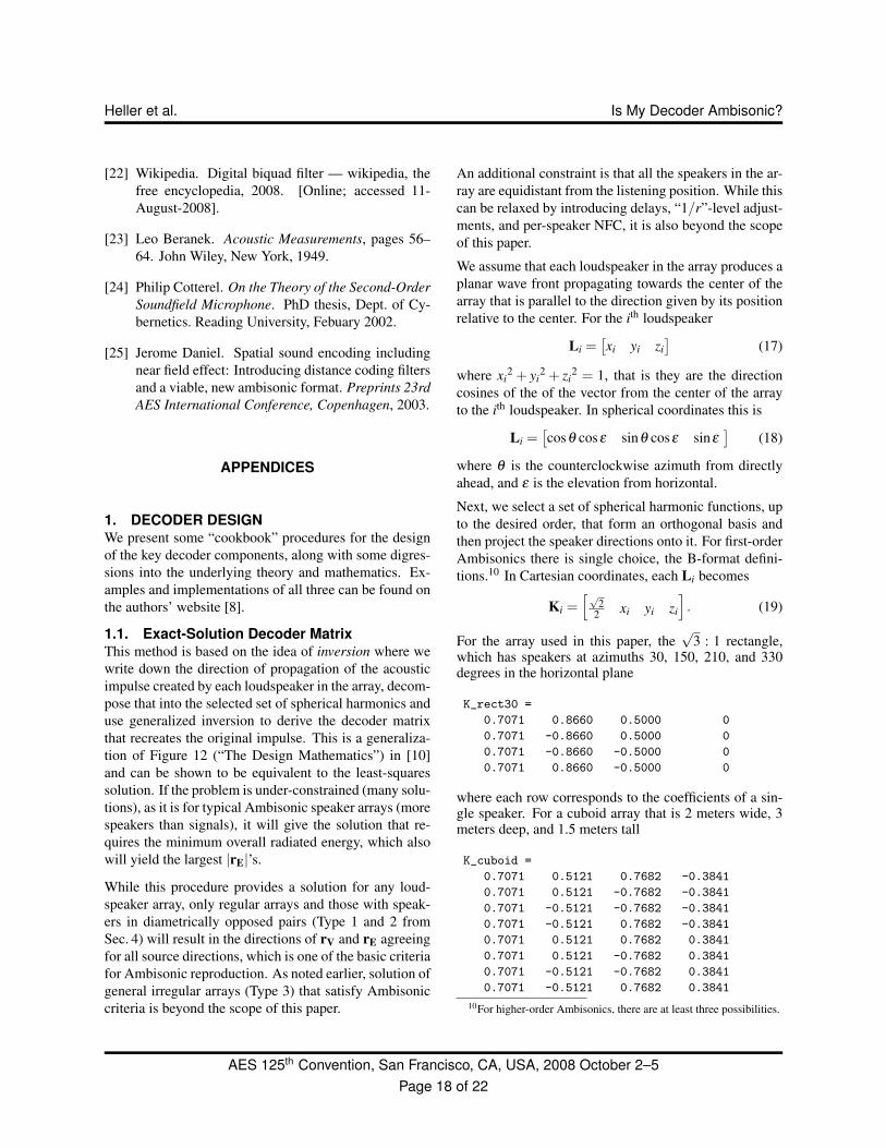
1.1. Exact-Solution Decoder MatrixThis method is based on the idea of inversion where wewrite down the direction of propagation of the acousticimpulse created by each loudspeaker in the array, decom-pose that into the selected set of spherical harmonics anduse generalized inversion to derive the decoder matrixthat recreates the original impulse. This is a generaliza-tion of Figure 12 (“The Design Mathematics”) in [10]and can be shown to be equivalent to the least-squaressolution. If the problem is under-constrained (many solu-tions), as it is for typical Ambisonic speaker arrays (morespeakers than signals), it will give the solution that re-quires the minimum overall radiated energy, which alsowill yield the largest |rE|’s.
While this procedure provides a solution for any loud-speaker array, only regular arrays and those with speak-ers in diametrically opposed pairs (Type 1 and 2 fromSec. 4) will result in the directions of rV and rE agreeingfor all source directions, which is one of the basic criteriafor Ambisonic reproduction. As noted earlier, solution ofgeneral irregular arrays (Type 3) that satisfy Ambisoniccriteria is beyond the scope of this paper.
An additional constraint is that all the speakers in the ar-ray are equidistant from the listening position. While thiscan be relaxed by introducing delays, “1/r”-level adjust-ments, and per-speaker NFC, it is also beyond the scopeof this paper.
We assume that each loudspeaker in the array produces aplanar wave front propagating towards the center of thearray that is parallel to the direction given by its positionrelative to the center. For the ith loudspeaker
Li =[xi yi zi
](17)
where xi2 + yi
2 + zi2 = 1, that is they are the direction
cosines of the of the vector from the center of the arrayto the ith loudspeaker. In spherical coordinates this is
Li =[cosθ cosε sinθ cosε sinε
](18)
where θ is the counterclockwise azimuth from directlyahead, and ε is the elevation from horizontal.
Next, we select a set of spherical harmonic functions, upto the desired order, that form an orthogonal basis andthen project the speaker directions onto it. For first-orderAmbisonics there is single choice, the B-format defini-tions.10 In Cartesian coordinates, each Li becomes
Ki =[√
22 xi yi zi
]. (19)
For the array used in this paper, the√
3 : 1 rectangle,which has speakers at azimuths 30, 150, 210, and 330degrees in the horizontal plane
K_rect30 =
0.7071 0.8660 0.5000 0
0.7071 -0.8660 0.5000 0
0.7071 -0.8660 -0.5000 0
0.7071 0.8660 -0.5000 0
where each row corresponds to the coefficients of a sin-gle speaker. For a cuboid array that is 2 meters wide, 3meters deep, and 1.5 meters tall
K_cuboid =
0.7071 0.5121 0.7682 -0.3841
0.7071 0.5121 -0.7682 -0.3841
0.7071 -0.5121 -0.7682 -0.3841
0.7071 -0.5121 0.7682 -0.3841
0.7071 0.5121 0.7682 0.3841
0.7071 0.5121 -0.7682 0.3841
0.7071 -0.5121 -0.7682 0.3841
0.7071 -0.5121 0.7682 0.3841
10For higher-order Ambisonics, there are at least three possibilities.
AES 125th Convention, San Francisco, CA, USA, 2008 October 2–5Page 18 of 22
Heller et al. Is My Decoder Ambisonic?
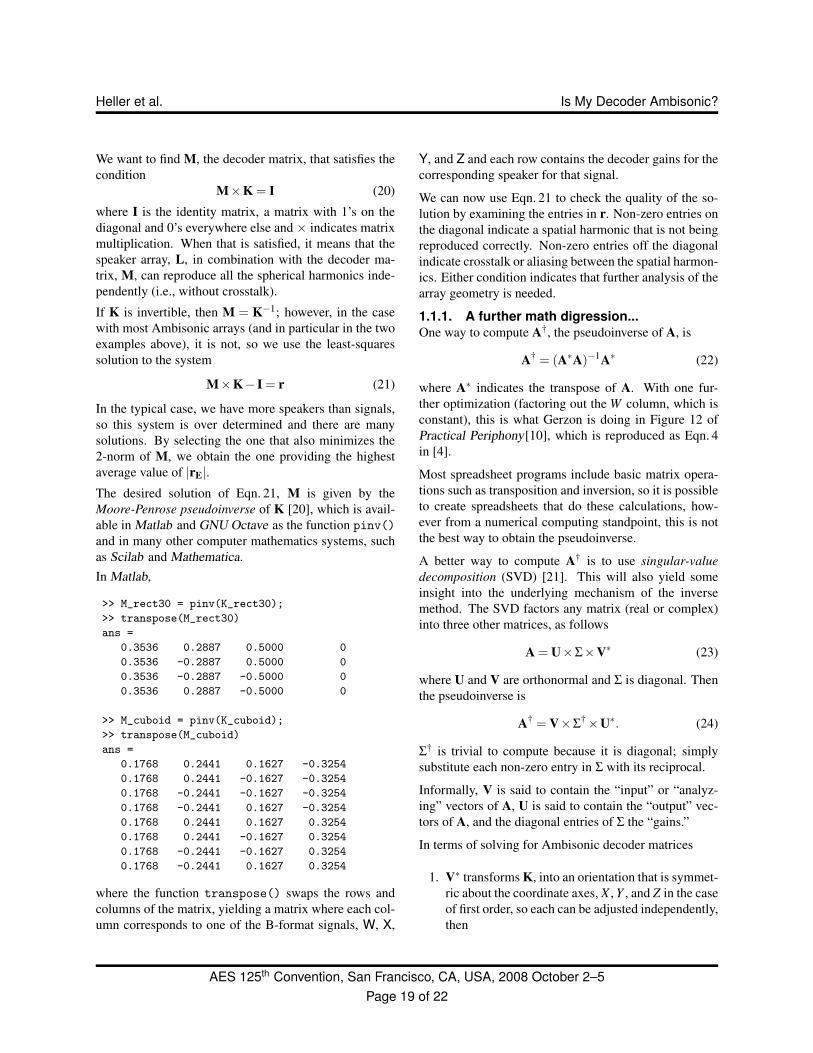
We want to find M, the decoder matrix, that satisfies thecondition
M×K = I (20)
where I is the identity matrix, a matrix with 1’s on thediagonal and 0’s everywhere else and × indicates matrixmultiplication. When that is satisfied, it means that thespeaker array, L, in combination with the decoder ma-trix, M, can reproduce all the spherical harmonics inde-pendently (i.e., without crosstalk).
If K is invertible, then M = K−1; however, in the casewith most Ambisonic arrays (and in particular in the twoexamples above), it is not, so we use the least-squaressolution to the system
M×K− I = r (21)
In the typical case, we have more speakers than signals,so this system is over determined and there are manysolutions. By selecting the one that also minimizes the2-norm of M, we obtain the one providing the highestaverage value of |rE|.The desired solution of Eqn. 21, M is given by theMoore-Penrose pseudoinverse of K [20], which is avail-able in Matlab and GNU Octave as the function pinv()and in many other computer mathematics systems, suchas Scilab and Mathematica.In Matlab,
>> M_rect30 = pinv(K_rect30);
>> transpose(M_rect30)
ans =
0.3536 0.2887 0.5000 0
0.3536 -0.2887 0.5000 0
0.3536 -0.2887 -0.5000 0
0.3536 0.2887 -0.5000 0
>> M_cuboid = pinv(K_cuboid);
>> transpose(M_cuboid)
ans =
0.1768 0.2441 0.1627 -0.3254
0.1768 0.2441 -0.1627 -0.3254
0.1768 -0.2441 -0.1627 -0.3254
0.1768 -0.2441 0.1627 -0.3254
0.1768 0.2441 0.1627 0.3254
0.1768 0.2441 -0.1627 0.3254
0.1768 -0.2441 -0.1627 0.3254
0.1768 -0.2441 0.1627 0.3254
where the function transpose() swaps the rows andcolumns of the matrix, yielding a matrix where each col-umn corresponds to one of the B-format signals, W, X,
Y, and Z and each row contains the decoder gains for thecorresponding speaker for that signal.
We can now use Eqn. 21 to check the quality of the so-lution by examining the entries in r. Non-zero entries onthe diagonal indicate a spatial harmonic that is not beingreproduced correctly. Non-zero entries off the diagonalindicate crosstalk or aliasing between the spatial harmon-ics. Either condition indicates that further analysis of thearray geometry is needed.
1.1.1. A further math digression...One way to compute A†, the pseudoinverse of A, is
A† = (A∗A)−1A∗ (22)
where A∗ indicates the transpose of A. With one fur-ther optimization (factoring out the W column, which isconstant), this is what Gerzon is doing in Figure 12 ofPractical Periphony[10], which is reproduced as Eqn. 4in [4].
Most spreadsheet programs include basic matrix opera-tions such as transposition and inversion, so it is possibleto create spreadsheets that do these calculations, how-ever from a numerical computing standpoint, this is notthe best way to obtain the pseudoinverse.
A better way to compute A† is to use singular-valuedecomposition (SVD) [21]. This will also yield someinsight into the underlying mechanism of the inversemethod. The SVD factors any matrix (real or complex)into three other matrices, as follows
A = U×Σ×V∗ (23)
where U and V are orthonormal and Σ is diagonal. Thenthe pseudoinverse is
A† = V×Σ†×U∗. (24)
Σ† is trivial to compute because it is diagonal; simplysubstitute each non-zero entry in Σ with its reciprocal.
Informally, V is said to contain the “input” or “analyz-ing” vectors of A, U is said to contain the “output” vec-tors of A, and the diagonal entries of Σ the “gains.”
In terms of solving for Ambisonic decoder matrices
1. V∗ transforms K, into an orientation that is symmet-ric about the coordinate axes, X , Y , and Z in the caseof first order, so each can be adjusted independently,then
AES 125th Convention, San Francisco, CA, USA, 2008 October 2–5Page 19 of 22

Heller et al. Is My Decoder Ambisonic?
2. Σ† adjusts the gain of each spherical harmonic, sothe pressure, velocity, and so forth, are correctly re-produced, which also assures that source directionsare correctly reproduced, and finally,
3. U returns everything to the original orientation ofthe speaker array.
The non-zero entries in Σ are called the singular valuesof A. In analyzing Ambisonic playback systems, if thenumber of singular values does not equal the number ofsignals in use, then the speaker array is not capable ofreproducing all the intended spherical harmonics. Thismay be a trivial result, for example that a horizontal arraycannot reproduce Z, or more significantly, that the arraygeometry is degenerate in some other way.
The ratio of the largest to the smallest singular value iscalled the condition of the matrix. This is related to theminimum and maximum values of rE , and hence givesus insight into the overall quality of localization the arraywill provide. For example, in Matlab
>> svd(K_rect30)
ans =
1.7321
1.4142
1.0000
0
indicates that one spherical harmonic will not be repro-duced (Z) and that rE will not be uniform in all direc-tions.
1.2. Phase-Matched Band-Splitting FiltersSec. 4 discussed the need for frequency-dependent pro-cessing in order to transition from the exact solution atlow-frequencies (LF), to one that optimizes rE at highfrequencies (HF). The crossover frequency use by Clas-sic Ambisonic Decoders and in our earlier listening testsis 380 Hz. We present the design of a suitable filter forthis.
The key idea is to treat the LF-to-HF transition as onewould the crossover network feeding the LF and HF unitsin a loudspeaker. We desire a gradual transition, so sim-ple second-order filters are used
LF(s) =1
1+2sT +(sT )2 (25)
HF(s) =(sT )2
1+2sT +(sT )2 (26)
These have the -6 dB point at the crossover frequencyω = 1/T rad/sec. If you combine these, the outputs can-cel at the crossover frequency, but reversing the phaseof the HF section, makes its phase match that of the LFsection and there is no cancellation at the crossover fre-quency. The output is
Total(s) =1− (sT )2
1+2sT +(sT )2 (27)
=(1+ sT )(1− sT )(1+ sT )(1+ sT )
(28)
=1− sT1+ sT
(29)
which is a first-order all-pass network. Hence, the phaseresponse is the same as the LF section and is maintainedregardless of the relative levels of the LF and HF sec-tions.
Applying the bilinear transformation to implement theseas digital infinite-impulse response (IIR) filters, thesecond-order pole
H(s) =1
1+2sT +(sT )2 (30)
becomes
H(z) =b0 +b1z−1 +b2z−2
a0 +a1z−1 +a2z−2)(31)
where, for the LF section
b0 =k2
k2 +2k +1(32)
b1 = 2b0 (33)b2 = b0 (34)a0 = 1 (35)
a1 =2(k2−1)
k2 +2k +1(36)
a2 =k2−2k +1k2 +2k +1
(37)
and, for the HF section
b0 =1
k2 +2k +1(38)
b1 =−2b0 (39)b2 = b0 (40)
with a0, a1, a2 as in the LF section and
k = tanπFc
Fs(41)
AES 125th Convention, San Francisco, CA, USA, 2008 October 2–5Page 20 of 22

Heller et al. Is My Decoder Ambisonic?
and Fc is the crossover frequency in Hz and Fs is the sam-ple rate.11
As an example, with Fc = 380 and Fs = 48000
b_lp =
0.000589143208472
0.001178286416944
0.000589143208472
b_hp =
0.952044598366767
-1.904089196733534
0.952044598366767
a =
1.000000000000000
-1.902910910316590
0.905267483150478
These filters can be implemented in Plogue Bidule asDirect Form 1 IIRs [22] using the Recursive Functionblock. The HF section is specified by entering
( 0.952044598366767 * x) +
(-1.904089196733534 * prevX(1)) +
( 0.952044598366767 * prevX(2)) -
(-1.902910910316590 * prevR(1)) -
( 0.905267483150478 * prevR(2))
and the LP section by entering
( 0.000589143208472 * x) +
( 0.001178286416944 * prevX(1)) +
( 0.000589143208472 * prevX(2)) -
(-1.902910910316590 * prevR(1)) -
( 0.905267483150478 * prevR(2))
Recall that the desired phase response is obtained by sub-tracting the output of these sections, so after scaling ac-cording to the desired response, the output signals mustbe differenced, not summed.
1.3. Near-Field Compensation FilterAll that is needed here is a first-order high-pass (HP) fil-ter
H(s) =s
1+ sT(42)
which translates to the digital IIR filter
H(z) =b0 +b1z−1
a0 +a1z−1 (43)
11Note that this k is not the same as the k used in Sec. 4.
Fig. 10: Frequency and phase response of 2-meter NFCfilter implemented as Direct Form 1 IIR with Bidule’srecursive function block.
with
b0 =1
k +1(44)
b1 =−b0 (45)a0 = 1 (46)a1 = (k−1)b0 (47)
where k is given by Eqn. 41.
As an example, for 2 meters, f-3dB = 27.1 Hz and Fs =48000
b =
0.998229447703366 -0.998229447703366
a =
1.000000000000000 -0.996458895406731
Implementing in Bidule’s recursive function block
( 0.998229447703366 * x) +
(-0.998229447703366 * prevX(1)) -
(-0.996458895406731 * prevR(1))
2. IS MY ENCODER AMBISONIC?Many references show the first-order horizontal Am-bisonic B-format encoding equations asW
XY
=
√
22
cosθ
sinθ
S (48)
AES 125th Convention, San Francisco, CA, USA, 2008 October 2–5Page 21 of 22
Heller et al. Is My Decoder Ambisonic?
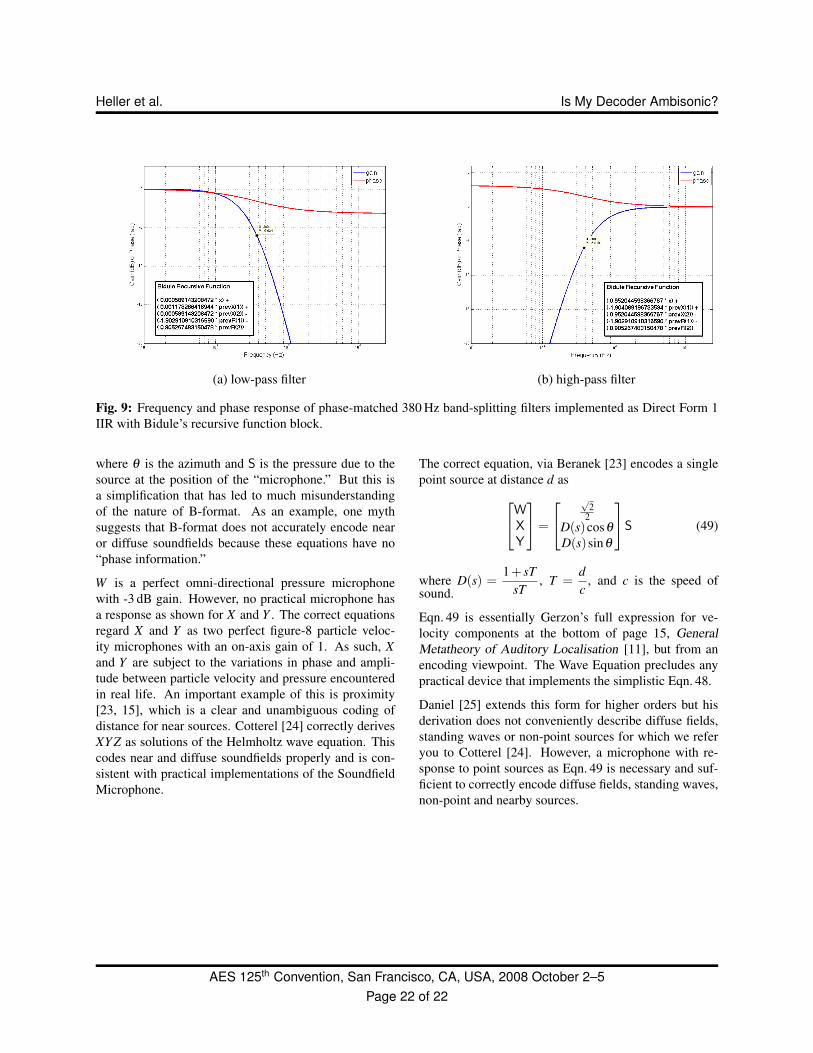
(a) low-pass filter (b) high-pass filter
Fig. 9: Frequency and phase response of phase-matched 380 Hz band-splitting filters implemented as Direct Form 1IIR with Bidule’s recursive function block.
where θ is the azimuth and S is the pressure due to thesource at the position of the “microphone.” But this isa simplification that has led to much misunderstandingof the nature of B-format. As an example, one mythsuggests that B-format does not accurately encode nearor diffuse soundfields because these equations have no“phase information.”
W is a perfect omni-directional pressure microphonewith -3 dB gain. However, no practical microphone hasa response as shown for X and Y . The correct equationsregard X and Y as two perfect figure-8 particle veloc-ity microphones with an on-axis gain of 1. As such, Xand Y are subject to the variations in phase and ampli-tude between particle velocity and pressure encounteredin real life. An important example of this is proximity[23, 15], which is a clear and unambiguous coding ofdistance for near sources. Cotterel [24] correctly derivesXY Z as solutions of the Helmholtz wave equation. Thiscodes near and diffuse soundfields properly and is con-sistent with practical implementations of the SoundfieldMicrophone.
The correct equation, via Beranek [23] encodes a singlepoint source at distance d asW
XY
=
√
22
D(s)cosθ
D(s)sinθ
S (49)
where D(s) =1+ sT
sT, T =
dc
, and c is the speed ofsound.
Eqn. 49 is essentially Gerzon’s full expression for ve-locity components at the bottom of page 15, GeneralMetatheory of Auditory Localisation [11], but from anencoding viewpoint. The Wave Equation precludes anypractical device that implements the simplistic Eqn. 48.
Daniel [25] extends this form for higher orders but hisderivation does not conveniently describe diffuse fields,standing waves or non-point sources for which we referyou to Cotterel [24]. However, a microphone with re-sponse to point sources as Eqn. 49 is necessary and suf-ficient to correctly encode diffuse fields, standing waves,non-point and nearby sources.
AES 125th Convention, San Francisco, CA, USA, 2008 October 2–5Page 22 of 22