audioxpress. reprinted by permission. for...
TRANSCRIPT

xpressaudioADVANCING THE EVOLUTION OF AUDIO TECHNOLOGY
www.audioxpress.comwww.audioxpress.com
FAST CompanyQSC’s Flexible Amplifier Summing Technology
INNOVATIONS IN AUDIO • AUDIO ELECTRONICS • THE BEST IN DIY AUDIO
Sound ControlWe Really Have (or Want) Great AcousticsRichard Honeycutt’s New Column
SpeakersAn Introduction to WoofersWelcome to the Low-Frequency World
Practical Test & MeasurementDesigning for Ultra-Low THD+N
You Can DIY!Speaker Rebuild with Heil TransformerResurrect Classic Speakers or Design a New System with DSP
NOVEMBER 2013
audioXpress. Reprinted by permission. For subscription information, call 800.269.6301, or visit www.audioxpress.com. Entire contents copyright © Segment LLC. All rights reserved.

You Can DIY!
46 | November 2013 | audioxpress.com
ax
When it comes to musical taste,
you cou ld proba-bly classify me as an
omnivore. Depending on my mood, I may lean toward classical,
jazz, rock, pop, country, or other genres. Like most of us, there is one special piece that goes directly into my heart, bypassing all logic to create an intense emotional involvement. For me, it is Gustav Mahler’s Symphony No. 2, “The Resurrection.” It is also a fitting title for my latest completed project.
What is an AMT?Several years ago, I became interested in the
Heil Air Motion Transformer technology. Created by Dr. Oskar Heil, this device uses an unorthodox mechanism to quickly accelerate air, resulting in a very interesting tweeter. There is a lot written about the actual mechanism, including several pat-ents leading up to the AMT version (see Resources).
But there is also a lot of misinformation on how it really works. It has been said that the diaphragm, which is a vertically aligned array of pleated mate-rial behaves like an accordion squeezing the air in and out. Actually, the whole diaphragm does not move in and out like an accordion, rather alternate folds move either in or out so the air is squeezed out one side and sucked in the other. The folds stop the diaphragm from moving back and forth so the result is a dipole pressure wave. For a bet-ter understanding of this device, please refer to the Resources section.
Heil AMT HistoryThe AMT was originally produced by the Califor-
nia company ESS, but the final complete speaker received mixed reviews. It was a two-way design that suffered from running the AMT at too low a frequency and the 12” woofer at too high a fre-quency. The two drivers’ radiation patterns were different because of their physical shapes and
By
Thomas Perazella(United States)
Tips to Resurrect a Classic Speaker or Design a New System (Part 1)Use a Heil Transformer and an Updated Woofer
Photo 1: The Eton 7” drive has a light rigid cone made of a Nomex honeycomb sandwiched between two Kevlar layers for true pistonic behavior.
This article is the first of a three-part series that will describe the history, construction, testing, problem solving, and
voicing of an old speaker brought back to life by new technology. Although the original goal was to breathe new life into a classic, many of the issues addressed here are also critical when designing a new speaker or even getting the best performance from commercial speakers and associated equipment.
audioXpress. Reprinted by permission. For subscription information, call 800.269.6301, or visit www.audioxpress.com. Entire contents copyright © Segment LLC. All rights reserved.
REPRINT
REPRINT
jazz, rock, pop, country, or other genres. Like most REPRINT
jazz, rock, pop, country, or other genres. Like most of us, there is one special piece that goes directly REPRIN
T
of us, there is one special piece that goes directly into my heart, bypassing all logic to create an REPRIN
T
into my heart, bypassing all logic to create an intense emotional involvement. For me, it is Gustav REPRIN
T
intense emotional involvement. For me, it is Gustav
(Part 1)
REPRINT
(Part 1)Use a Heil Transformer and an
REPRINTUse a Heil Transformer and an
Photo 1: The Eton 7” drive REPRINT
Photo 1: The Eton 7” drive has a light rigid cone made REPRIN
T
has a light rigid cone made of a Nomex honeycomb REPRIN
T
of a Nomex honeycomb sandwiched between two REPRIN
T
sandwiched between two
This article is the first of a three-part series that will describe
REPRINT
This article is the first of a three-part series that will describe the history, construction, testing, problem solving, and
REPRINT
the history, construction, testing, problem solving, and voicing of an old speaker brought back to life by new
REPRINT
voicing of an old speaker brought back to life by new technology. Although the original goal was to breathe
REPRINT
technology. Although the original goal was to breathe new life into a classic, many of the issues addressed
REPRINT
new life into a classic, many of the issues addressed here are also critical when designing a new speaker or
REPRINT
here are also critical when designing a new speaker or even getting the best performance from commercial
REPRINT
even getting the best performance from commercial speakers and associated equipment.
REPRINT
speakers and associated equipment.

audioxpress.com | November 2013 | 47
the wavelengths reproduced vs. the size of each throughout their crossover frequency ranges. Also, one was used in open air as a dipole and the other in a box as a monopole. The AMT’s crossover point and slopes caused it to operate at the low end in a range that did not work with the given slopes. The resulting speaker did not live up to the AMT’s true performance capabilities. In spite of this, people loved the speaker so much it almost became a cult classic because of the AMT’s crystalline response.
I do not remember exactly when I decided to use the AMT as the basis of a DIY project, but it was probably in the late 1980s or early 1990s. I obtained a used pair of the tweeters and imme-diately knew I would have to use a three-way configuration if I was going to be able to get a wide enough dynamic range without exposing the tweeter to undue stress. I would also have a chance to better control the integration of the drivers’ radiation patterns.
Although a three-driver three-way is a com-mon configuration, some severe compromises in a one-driver-per-frequency-range configuration must be addressed. Primarily, they have to do with sensitivity, linear displacement capability, and power requirements, which I recalled during the implementation. It also reminded me why I moved on to other solutions. However, the concept has validity because of its smaller size and lower cost.
My Original ProjectThe speaker concept used a sealed box holding
a dynamic driver for the bass, a dipole mounted dynamic driver for the midrange, and the AMT as a dipole for the high frequencies. I located a woofer box and grille used in an exceptionally well-performing speaker, the Acarian Alon IV. It was designed for a sealed-box woofer and a dipole-mounted midrange and tweeter (see Resources for more information). I then had to choose the bass and midrange drivers.
When I designed the original speaker, the Ger-man company Eton had developed a woofer/mid-range driver that used what it called “Hexacone” technology. The cone was made from a Nomex honeycomb sandwiched between two Kevlar layers (see Photo 1). The result was a cone that was very light but extremely rigid. Within a certain range, it acted like the ideal piston.
In addition to the sandwich cone, the Eton woofer/driver had an inverted soft rubber sur-round. The result was a relatively smooth, low-dis-tortion output, even when driven hard. There were some ripples in the passband and if you went up in frequency, an anomaly in the frequency response
would appear. I have been told that the ragged response at higher frequencies was due to a dif-ference in impedance between the rigid cone and the compliant surround that resulted in reflections of energy back into the cone at the higher frequen-cies. I cannot verify the actual mechanism myself, but response problems do appear.
The solution to using a driver that has great performance in most of its range but problems at frequency extremes is simple. Don’t use the driver in the problem areas. That may be prob-lematic when using passive crossovers, but with the flexible electronic crossovers now available, it has become a non-issue. At the time, I decided to use the Eton woofer/driver with a home-built 12-dB/octave electronic crossover. I mounted it in a quasi-dipole configuration with an open back but heavy damping. As it turns out, that was okay, but not the best solution.
The original AMT driver was mounted in a plas-tic housing that had a ridge around the front and back that created triangular-shaped cavities at the top and bottom in the front and rear of the radiating element. Although I had no way to mea-sure those cavities’ effects, I altered them by fill-ing the cavities with wool carpet underlayment
Photo 2: The cavities in the Heil AMT housing were filled with deadening material in an attempt to reduce cavity resonances.
Photo 3: The baffle housing the midrange and tweeter is isolated from the bass cabinet by a rubber sheet and rubber tubing in the holes that receive the indexing pins.
audioXpress. Reprinted by permission. For subscription information, call 800.269.6301, or visit www.audioxpress.com. Entire contents copyright © Segment LLC. All rights reserved.
REPRINT
REPRINT
REPRINT
REPRINT
REPRINT
implementation. It also reminded me why I moved
REPRINT
implementation. It also reminded me why I moved on to other solutions. However, the concept has
REPRINT
on to other solutions. However, the concept has validity because of its smaller size and lower cost.
REPRINT
validity because of its smaller size and lower cost.
The speaker concept used a sealed box holding
REPRINT
The speaker concept used a sealed box holding a dynamic driver for the bass, a dipole mounted
REPRINT
a dynamic driver for the bass, a dipole mounted dynamic driver for the midrange, and the AMT
REPRINT
dynamic driver for the midrange, and the AMT as a dipole for the high frequencies. I located
REPRINT
as a dipole for the high frequencies. I located a woofer box and grille used in an exceptionally
REPRINT
a woofer box and grille used in an exceptionally well-performing speaker, the Acarian Alon IV. It
REPRINT
well-performing speaker, the Acarian Alon IV. It was designed for a sealed-box woofer and a dipole-
REPRINT
was designed for a sealed-box woofer and a dipole-mounted midrange and tweeter (see Resources for REPRIN
T
mounted midrange and tweeter (see Resources for more information). I then had to choose the bass REPRIN
T
more information). I then had to choose the bass and midrange drivers. REPRIN
T
and midrange drivers.When I designed the original speaker, the GerREPRIN
T
When I designed the original speaker, the German company Eton had developed a woofer/midREPRIN
T
man company Eton had developed a woofer/midrange driver that used what it called “Hexacone” REPRIN
T
range driver that used what it called “Hexacone” The cone was made from a Nomex REPRIN
T
The cone was made from a Nomex
would appear. I have been told that the ragged
REPRINT
would appear. I have been told that the ragged response at higher frequencies was due to a dif
REPRINT
response at higher frequencies was due to a difference in impedance between the rigid cone and
REPRINT
ference in impedance between the rigid cone and the compliant surround that resulted in reflections
REPRINT
the compliant surround that resulted in reflections of energy back into the cone at the higher frequen
REPRINT
of energy back into the cone at the higher frequencies. I cannot verify the actual mechanism myself,
REPRINT
cies. I cannot verify the actual mechanism myself, but response problems do appear.
REPRINT
but response problems do appear.
REPRINT
REPRINT
REPRINTPhoto 2: The cavities in the Heil AMT housing were filled with deadening material in an
REPRINTPhoto 2: The cavities in the Heil AMT housing were filled with deadening material in an
attempt to reduce cavity resonances.
REPRINTattempt to reduce cavity resonances.

You Can DIY!
48 | November 2013 | audioxpress.com
axmaterial. In addition, I fastened some thin black felt material over the faces of the pole pieces to improve the tweeter’s looks and possibly reduce some reflected energy (see Photo 2). It is inter-esting to note that the AMT’s current version has the cavities removed from the housing and has added what appears to be a black surface-finish treatment on the pole pieces.
Both the AMT and the Eton drivers were mounted on a flat baffle that sat on top of the woofer box in positions to time align the three driv-ers. I added mass to the baffle base in the form of a box containing cement. I used sand-filled steel tubes to brace the baffle’s upright section to the base. The baffle was located on the woofer hous-ing with steel pins fastened to the housing and slip fitted into holes in the baffle’s base. I used surgical rubber tubing inserts to isolate the base from any vibration that may have come up the pins. The baffle’s base also had a rubber sheet on the bottom for isolation. Photo 3 shows the layout of the baffle’s base.
For the bass range, I originally used 12” driv-ers that I already had. However, they did not have much linear excursion, so I switched to 10” Peer-less drivers. They were better, but the additional excursion hardly made up for the loss in cone area. Ultimately I used 12” drivers from HSU Research that had a higher XMAX and a larger cone area. Photo 4 shows the completed speaker.
I used those speakers for many years with good results. However, as time went on, I realized they had limitations, including limited bass excursion and a radiation pattern that resulted in more floor and ceiling reflections than I preferred. Ultimately, I replaced them with my current main system that uses Bohlender-Graebener RD75 drivers for the high frequencies, Peerless 831727 10” drivers for the upper bass/lower midrange, and sealed box
subwoofers. (More information about these drivers and midranges is available in my article series, “ On Angels Wings,” Part 1 and 2, audioXpress, January–February, 2001 and “A Dipole Midbass,” Part 1 and 2, audioXpress, June–July 2004.) The Heil-based speakers were put into storage. With the AMT tweeters available to the public once again, I decided to see if I could improve on the origi-nal design, especially since a range of powerful reasonably priced digital signal processing (DSP) equipment is available.
Updating the DesignAlthough the AMT and Eton drivers have under-
gone revisions over the years, both versions I had are still adequate for the job so I did not replace them. Woofer designs, however, have progressed dramatically in the intervening time. The search was on to find a suitable substitute.
A major advantage of current speaker control devices is that trying to achieve the woofer’s critical tuning in an enclosure is not as much a necessity as in the past. For example, if you use a passive crossover with an incorrect speaker parameters and box volume combination, you may wind up with a Qb that is too high. The result would be a bump in the frequency response at resonance. In the past, that could result in an overly bass-heavy voicing. Most DSP-based electronic cross-overs enable you to create a bandpass filter with any center frequency, Q, and any amplitude you desire to flatten out the response bump. Because of this, if you already have an enclosure as I did or are restricted by severe space limitations, your driver choices are greatly expanded. You do not have to worry about achieving critical damping by choosing from a limited range of drivers with the correct parameters for the given box size.
The WooferWhen it comes to speakers with drivers cover-
ing separate frequency ranges, the woofer is the group’s heavy lifter. For each octave the repro-duced frequency decreases, four times the volume displacement of air is necessary to maintain the same sound pressure level (SPL). If you need “X” amount of volume displacement to achieve your desired SPL at 20 kHz, at 20 Hz you need more than 4 million times “X” to achieve the same SPL. Fortunately, music does not produce the same SPLs at the highest frequencies as in the bass, but it quickly becomes apparent why so few speakers can reproduce high-amplitude organ pedal notes at realistic listening levels without excessive dis-tortion, if even at all.
Photo 4: The original speaker used an HSU 12” bass driver, which is shown without the grille.
Photo 5: The Dayton Ultimax UM12-22 woofer has several great features, including 19-mm XMAX.
audioXpress. Reprinted by permission. For subscription information, call 800.269.6301, or visit www.audioxpress.com. Entire contents copyright © Segment LLC. All rights reserved.
REPRINT
I decided to see if I could improve on the origi
REPRINT
I decided to see if I could improve on the original design, especially since a range of powerful
REPRINT
nal design, especially since a range of powerful reasonably priced digital signal processing (DSP)
REPRINT
reasonably priced digital signal processing (DSP) equipment is available.
REPRINTequipment is available.
Updating the Design
REPRINTUpdating the Design
Although the AMT and Eton drivers have under
REPRINTAlthough the AMT and Eton drivers have under
REPRINTslip fitted into holes in the baffle’s base. I used
REPRINTslip fitted into holes in the baffle’s base. I used
surgical rubber tubing inserts to isolate the base
REPRINT
surgical rubber tubing inserts to isolate the base from any vibration that may have come up the
REPRINT
from any vibration that may have come up the pins. The baffle’s base also had a rubber sheet on
REPRINT
pins. The baffle’s base also had a rubber sheet on shows the layout
REPRINT
shows the layout
For the bass range, I originally used 12” driv
REPRINT
For the bass range, I originally used 12” driv-
REPRINT
-ers that I already had. However, they did not have
REPRINT
ers that I already had. However, they did not have much linear excursion, so I switched to 10” Peer
REPRINT
much linear excursion, so I switched to 10” Peer-
REPRINT
-less drivers. They were better, but the additional
REPRINT
less drivers. They were better, but the additional excursion hardly made up for the loss in cone area.
REPRINT
excursion hardly made up for the loss in cone area. Ultimately I used 12” drivers from HSU Research
REPRINT
Ultimately I used 12” drivers from HSU Research that had a higher X
REPRINT
that had a higher XMAX
REPRINT
MAX and a larger cone area.
REPRINT
and a larger cone area. shows the completed speaker.
REPRINT
shows the completed speaker. I used those speakers for many years with good
REPRINT
I used those speakers for many years with good results. However, as time went on, I realized they
REPRINT
results. However, as time went on, I realized they had limitations, including limited bass excursion
REPRINT
had limitations, including limited bass excursion and a radiation pattern that resulted in more floor
REPRINT
and a radiation pattern that resulted in more floor and ceiling reflections than I preferred. Ultimately,
REPRINT
and ceiling reflections than I preferred. Ultimately, I replaced them with my current main system that
REPRINT
I replaced them with my current main system that uses Bohlender-Graebener RD75 drivers for the
REPRINT
uses Bohlender-Graebener RD75 drivers for the high frequencies, Peerless 831727 10” drivers for
REPRINT
high frequencies, Peerless 831727 10” drivers for the upper bass/lower midrange, and sealed box REPRIN
T
the upper bass/lower midrange, and sealed box
gone revisions over the years, both versions I had
REPRINTgone revisions over the years, both versions I had
are still adequate for the job so I did not replace
REPRINTare still adequate for the job so I did not replace
them. Woofer designs, however, have progressed
REPRINTthem. Woofer designs, however, have progressed
dramatically in the intervening time. The search
REPRINT
dramatically in the intervening time. The search was on to find a suitable substitute.
REPRINT
was on to find a suitable substitute.A major advantage of current speaker control
REPRINT
A major advantage of current speaker control devices is that trying to achieve the woofer’s critical
REPRINT
devices is that trying to achieve the woofer’s critical tuning in an enclosure is not as much a necessity
REPRINT
tuning in an enclosure is not as much a necessity as in the past. For example, if you use a passive
REPRINT
as in the past. For example, if you use a passive crossover with an incorrect speaker parameters
REPRINT
crossover with an incorrect speaker parameters and box volume combination, you may wind up
REPRINT
and box volume combination, you may wind up with a Qb that is too high. The result would be
REPRINT
with a Qb that is too high. The result would be
REPRINT

audioxpress.com | November 2013 | 49
To achieve the high linear volume displacements necessary for clean bass, you need a lot of radi-ating surface combined with a lot of linear excur-sion. It is similar to an internal combustion engine where displacement is a product of the cylinder bore times the piston stroke times the number of cylinders. If the engine needs more displacement, you must have some combination of more pistons, bigger pistons, or a longer stroke for the pistons.
In this speaker’s case, the “bore” was limited to a 12” driver and the number of “cylinders” or woofers in each speaker was one. To get the vol-ume up to a reasonable level, a high linear “stroke” or excursion was needed.
The specification for a dynamic driver’s max-imum linear one-way excursion is XMAX. It is the excursion where either the motor force factor (Bl) falls to 50% of its peak value or the suspension stiffness (KMS) increases to double the initial value. XMAX is defined as the direction of travel either in or out that has the worst of either of the limit-ing values.
For example, if a driver is limited to 5-mm travel in one direction by force factor reduction and is limited in the other direction by increased stiffness at 4 mm, the driver’s XMAX will be 4 mm. Unfortunately, some manufacturers quote maxi-mum total excursion in both directions regardless of either parameter’s nonlinearity as the excursion instead of true XMAX. Caveat emptor!
In previous woofer designs, I used drivers from various companies that had different lin-ear excursion vs. price combinations. Some have incredibly high linear volume displacements in small drivers but at a high price. Over the years, my best results for drivers with high linear dis-placement at reasonable prices have come from Dayton Audio, the house brand of Parts Express. My current reference system uses two Dayton 15” DVC woofers that provide yeoman service for a two-driver arrangement.
Looking at the Parts Express website, the sub-woofer section brought me to a relatively new series of drivers called “Ultimax.” This series con-sists of three drivers in 10”, 12”, and 15” diame-ters. They all have similar features, which can be viewed on the website. One with a 19-mm XMAX(which is huge for a driver in this price range) was really impressive. I decided to use the Day-ton Audio UM12-22 12” driver. It was not so many years ago that drivers with these specifications would have been unheard of, let alone affordably priced. Anyone who refers to “the good old days” obviously didn’t build speakers. I purchased two units (see Photo 5).
Mounting the WoofersAfter receiving the new woofers, I removed the
old ones from the enclosures to see what modifica-tions were needed to fit the new drivers. The new drivers turned out to be 0.25” larger in outside diameter than the old ones, so I had to enlarge the original mounting holes to accept the baskets. In addition, the mounting flanges and surrounds were a bit thicker. To provide clearance for the grilles and give it a more finished look, I recessed the drivers further into the housing.
This combination presented two challenges. The first was that I no longer had a center hole to use with my Jasper jig and router to enlarge the hole. The second was that, even though the enclosure’s front panel was 1” thick, the amount of recess I desired would leave too little material after routing to securely fasten the drivers.
To solve these problems, I decided to use a backing plate mounted to the inside of the enclo-sures. First, I cut out two pieces of 0.75” MDF to mount inside the enclosures. The pieces covered the existing holes and extended far enough to pro-vide the necessary strength to mount the drivers. They also acted as a support for the router I used to enlarge the hole’s diameter. Two pieces were cut to fit inside the enclosure at the front.
A small problem cropped up when I tried to insert the backers. The enclosure’s walls had addi-tional 0.5” thick MDF plates with deadening mate-rial fastened to the inside to reduce vibrations. Because of the backers’ size, the edges of the plates attached to the sides interfered with the backers. I removed, trimmed, and set them aside to be refastened inside the housing after all the work on the backers was completed. Then, I tem-porarily screwed the backers into place against the front plate.
Next, I fabricated a temporary pivot plate to fill the existing hole flush with the enclosure front.
Photo 6: A pivot plate was constructed and inserted into the original woofer mounting hole to provide the alignment point necessary for the Jasper jig and router to properly enlarge the hole (a). The enlarged hole in the bass cabinet is shown with the backer plate and pivot hole before routing of the lower basket clearance hole (b).
a) b)
About the AuthorThomas Perazella is a retired IT director. He received a BS from the University of California, Berkeley campus. He is a member of the Audio Engineering Society, the Boston Audio Society, and the DC Audio DIY group. He has written for Speaker Builder and au-dioXpress magazines. He has authored several ar-ticles in professional au-dio journals and taught commercial lighting at the Winona School of Photography.
audioXpress. Reprinted by permission. For subscription information, call 800.269.6301, or visit www.audioxpress.com. Entire contents copyright © Segment LLC. All rights reserved.
REPRINT
REPRINTAfter receiving the new woofers, I removed the
REPRINTAfter receiving the new woofers, I removed the
old ones from the enclosures to see what modifica
REPRINT
old ones from the enclosures to see what modifica-
REPRINT
-tions were needed to fit the new drivers. The new
REPRINT
tions were needed to fit the new drivers. The new drivers turned out to be 0.25” larger in outside
REPRINT
drivers turned out to be 0.25” larger in outside diameter than the old ones, so I had to enlarge
REPRINT
diameter than the old ones, so I had to enlarge the original mounting holes to accept the baskets.
REPRINT
the original mounting holes to accept the baskets. In addition, the mounting flanges and surrounds
REPRINT
In addition, the mounting flanges and surrounds were a bit thicker. To provide clearance for the
REPRINT
were a bit thicker. To provide clearance for the grilles and give it a more finished look, I recessed
REPRINT
grilles and give it a more finished look, I recessed
REPRINT
mum total excursion in both directions regardless
REPRINT
mum total excursion in both directions regardless of either parameter’s nonlinearity as the excursion
REPRINT
of either parameter’s nonlinearity as the excursion
In previous woofer designs, I used drivers
REPRINT
In previous woofer designs, I used drivers from various companies that had different lin
REPRINT
from various companies that had different lin-
REPRINT
-ear excursion vs. price combinations. Some have
REPRINT
ear excursion vs. price combinations. Some have credibly high linear volume displacements in
REPRINT
credibly high linear volume displacements in small drivers but at a high price. Over the years,
REPRINT
small drivers but at a high price. Over the years, my best results for drivers with high linear dis
REPRINT
my best results for drivers with high linear dis-
REPRINT
-placement at reasonable prices have come from
REPRINT
placement at reasonable prices have come from yton Audio, the house brand of Parts Express.
REPRINT
yton Audio, the house brand of Parts Express. My current reference system uses two Dayton 15” REPRIN
T
My current reference system uses two Dayton 15” DVC woofers that provide yeoman service for a REPRIN
T
DVC woofers that provide yeoman service for a two-driver arrangement.REPRIN
T
two-driver arrangement.Looking at the Parts Express website, the subREPRIN
T
Looking at the Parts Express website, the subwoofer section brought me to a relatively new REPRIN
T
woofer section brought me to a relatively new series of drivers called “Ultimax.” This series conREPRIN
T
series of drivers called “Ultimax.” This series consists of three drivers in 10”, 12”, and 15” diameREPRIN
T
sists of three drivers in 10”, 12”, and 15” diame
the drivers further into the housing.
REPRINT
the drivers further into the housing. This combination presented two challenges.
REPRINT
This combination presented two challenges. The first was that I no longer had a center hole
REPRINT
The first was that I no longer had a center hole to use with my Jasper jig and router to enlarge
REPRINT
to use with my Jasper jig and router to enlarge the hole. The second was that, even though the
REPRINT
the hole. The second was that, even though the enclosure’s front panel was 1” thick, the amount
REPRINT
enclosure’s front panel was 1” thick, the amount of recess I desired would leave too little material
REPRINT
of recess I desired would leave too little material after routing to securely fasten the drivers.
REPRINT
after routing to securely fasten the drivers.To solve these problems, I decided to use a
REPRINT
To solve these problems, I decided to use a backing plate mounted to the inside of the enclo
REPRINT
backing plate mounted to the inside of the enclosures. First, I cut out two pieces of 0.75” MDF to
REPRINT
sures. First, I cut out two pieces of 0.75” MDF to
Photo 6: A pivot plate was constructed and inserted into the original woofer mounting
REPRINT
Photo 6: A pivot plate was constructed and inserted into the original woofer mounting hole to provide the alignment point necessary for the Jasper jig and router to properly
REPRINThole to provide the alignment point necessary for the Jasper jig and router to properly
enlarge the hole (a). The enlarged hole in the bass cabinet is shown with the backer plate
REPRINTenlarge the hole (a). The enlarged hole in the bass cabinet is shown with the backer plate
and pivot hole before routing of the lower basket clearance hole (b).
REPRINTand pivot hole before routing of the lower basket clearance hole (b).
REPRINT
REPRINT

You Can DIY!
50 | November 2013 | audioxpress.com
ax
This plate enabled the router to smoothly slide over the enclosure and provide the necessary pivot hole for the Jasper jig. I used a scrap piece of plywood for the plate that was not quite thick enough to present a totally flush surface by itself. I used sev-eral temporary shims of the proper thickness on top of the backer to solve the problem. I screwed the plate to the backer with four flat head wood
screws and I drilled not only through the plate but on through the backer to make a pilot hole for the jig. This assured me that the enclosure’s newly routed outside clearance hole would be exactly in line with the inside driver frame clearance hole that I later routed (see Photo 6a).
Then, I set the proper spacing on the Jasper jig and routed the new mounting hole in the enclo-sure. Once the hole was finished, I removed the pivot plate and checked its fit with the driver. Note that the backer plate has the four holes that were used to fasten the pivot plate and also the pivot hole that was then used to route the clear-ance hole in the backer. Because the new driver needed extra depth, the additional routing opened two small holes into the original enclosure’s inside (see Photo 6b). Although they would be covered by the driver frame and gasket, I decided to use the wood filler to ensure the enclosure was sealed.
Next, I removed the backers and routed the clearance holes through which the rear of the driver baskets would fit. When that was done, I glued the backers and screwed them to the enclosure’s inside using the same holes to ensure alignment. I replaced the damping plates. Then I masked, primed, and painted the front of the enclosure.
To maximize the enclosure’s apparent inside volume, I stuffed it with the fiber material that had been used in the original speaker. Next I wired the drivers using 12-gauge zip cord and a single piece of 12-gauge wire as a jumper between the two voice coils. To achieve 4-Ω impedance, the two 2-Ω coils on each driver were wired in series with one coil’s negative terminal wired to the other’s posi-tive terminal. I wired the remaining positive and negative terminals from each of the two coils to the input terminals on the enclosure (see Photo 7). I used McFeely’s #8 black-oxide square drive wood screws to fasten the two woofers. I have been using square drive screws in critical applications for years as they eliminate the “camming” that often happens with Phillips screws. McFeely’s has a good selection. The results provided a secure mounting for the woofers and, with the additional depth to the recess, a clean look. Next I moved on to the midrange and treble sections.
I will cover the remainder of the construction phase plus some problem solving in Part 2 of this article series. I will continue with problem solving plus voicing and music correction curves in the final article in this series. ax
Photo 7: The woofer terminals were connected to the terminal plate using 12-gauge zip cord. A 12-gauge jumper was used to tie the two voice coils together in series.
ResourcesR. Deutsch, “Acarian Alón IV loudspeaker,” 2006, www.stereophile.com/floor loudspeakers/293acarian/index.html.
Eton, “Home Hi-Fi,” www.etongmbh.de/en/products/home-hifi/midrange-bass- midrange/7-360-37-hex/1/pid/163.
Parts Express, www.partsexpress.com.
T. Perazella, “On Angels Wings, Part 1,” audioXpress, January 2001.
———, “On Angels Wings, Part 2,” audioXpress, February 2001.
———, “A Dipole Midbass, Part 1,” audioXpress, June 2004.
———, “A Dipole Midbass, Part 2,” audioXpress, July 2004.
US Patent and Trademark Office, Oskar Heil patents, www.google.com/patents/US3636278.
———, Oskar Heil patents, www.google.com/patents/US3832499.
Wikepedia, “Air Motion Transformer,” http://en.wikipedia.org/wiki/Air_Motion_ Transformer.
———, Oskar Heil, http://en.wikipedia.org/wiki/Oskar_Heil.
SourcesUltra Drive Pro DCX2496 crossover and Ultra Curve Pro DEQ2496 equalizerBehringer | www.behringer.com
UM12-22 Ultimax DVC subwooferDayton Audio | www.daytonaudio.com
Heil Air-Motion Transformer tweeterESS Laboratories | www.essspeakersusa.com
5-880/25 Hex midrangeEton GMBH | www.etongmbh.de
audioXpress. Reprinted by permission. For subscription information, call 800.269.6301, or visit www.audioxpress.com. Entire contents copyright © Segment LLC. All rights reserved.
REPRINTfor the plate that was not quite thick enough to
REPRINTfor the plate that was not quite thick enough to
present a totally flush surface by itself. I used sev
REPRINT
present a totally flush surface by itself. I used sev-
REPRINT
-eral temporary shims of the proper thickness on
REPRINT
eral temporary shims of the proper thickness on top of the backer to solve the problem. I screwed
REPRINT
top of the backer to solve the problem. I screwed the plate to the backer with four flat head wood
REPRINT
the plate to the backer with four flat head wood
and routed the new mounting hole in the enclo
REPRINT
and routed the new mounting hole in the enclosure. Once the hole was finished, I removed the
REPRINT
sure. Once the hole was finished, I removed the pivot plate and checked its fit with the driver.
REPRINT
pivot plate and checked its fit with the driver. Note that the backer plate has the four holes that
REPRINTNote that the backer plate has the four holes that
were used to fasten the pivot plate and also the
REPRINTwere used to fasten the pivot plate and also the
pivot hole that was then used to route the clear
REPRINTpivot hole that was then used to route the clear
ance hole in the backer. Because the new driver
REPRINTance hole in the backer. Because the new driver
needed extra depth, the additional routing opened
REPRINTneeded extra depth, the additional routing opened
two small holes into the original enclosure’s inside
REPRINTtwo small holes into the original enclosure’s inside
(see
REPRINT(see Photo 6b
REPRINTPhoto 6b). Although they would be covered
REPRINT). Although they would be covered
by the driver frame and gasket, I decided to use
REPRINT
by the driver frame and gasket, I decided to use the wood filler to ensure the enclosure was sealed.
REPRINT
the wood filler to ensure the enclosure was sealed. Next, I removed the backers and routed the
REPRINT
Next, I removed the backers and routed the clearance holes through which the rear of the driver
REPRINT
clearance holes through which the rear of the driver baskets would fit. When that was done, I glued
REPRINT
baskets would fit. When that was done, I glued the backers and screwed them to the enclosure’s
REPRINT
the backers and screwed them to the enclosure’s inside using the same holes to ensure alignment.
REPRINT
inside using the same holes to ensure alignment. I replaced the damping plates. Then I masked,
REPRINT
I replaced the damping plates. Then I masked, primed, and painted the front of the enclosure.
REPRINT
primed, and painted the front of the enclosure.
REPRINT
R. Deutsch, “Acarian Alón IV loudspeaker,” 2006, www.stereophile.com/floor
REPRINT
R. Deutsch, “Acarian Alón IV loudspeaker,” 2006, www.stereophile.com/floor
Eton, “Home Hi-Fi,” www.etongmbh.de/en/products/home-hifi/midrange-bass-
REPRINT
Eton, “Home Hi-Fi,” www.etongmbh.de/en/products/home-hifi/midrange-bass-
Parts Express, www.partsexpress.com.
REPRINT
Parts Express, www.partsexpress.com.
REPRINT
T. Perazella, “On Angels Wings, Part 1,”
REPRINT
T. Perazella, “On Angels Wings, Part 1,” audioXpress
REPRINT
audioXpress, January 2001.
REPRINT
, January 2001.
———, “On Angels Wings, Part 2,”
REPRINT
———, “On Angels Wings, Part 2,” audioXpress
REPRINT
audioXpress, February 2001.
REPRINT
, February 2001.
———, “A Dipole Midbass, Part 1,”
REPRINT
———, “A Dipole Midbass, Part 1,” audioXpress
REPRINT
audioXpress, June 2004.
REPRINT
, June 2004.
———, “A Dipole Midbass, Part 2,”
REPRINT
———, “A Dipole Midbass, Part 2,” audioXpress
REPRINT
audioXpress, July 2004.
REPRINT
, July 2004.
US Patent and Trademark Office, Oskar Heil patents, www.google.com/patents/
REPRINT
US Patent and Trademark Office, Oskar Heil patents, www.google.com/patents/US3636278.
REPRINT
US3636278.
———, Oskar Heil patents, www.google.com/patents/US3832499.REPRINT
———, Oskar Heil patents, www.google.com/patents/US3832499.
, “Air Motion Transformer,” http://en.wikipedia.org/wiki/Air_Motion_REPRINT
, “Air Motion Transformer,” http://en.wikipedia.org/wiki/Air_Motion_REPRINT
———, Oskar Heil, http://en.wikipedia.org/wiki/Oskar_Heil.REPRINT
———, Oskar Heil, http://en.wikipedia.org/wiki/Oskar_Heil.

xpressaudioADVANCING THE EVOLUTION OF AUDIO TECHNOLOGY
www.audioxpress.comwww.audioxpress.com
INNOVATIONS IN AUDIO • AUDIO ELECTRONICS • THE BEST IN DIY AUDIO
elysia xfilter 500Surface-Mount Magic in a Small Format
Acoustical AbsorptionThe Oldest Tool in the Modern Acoustician’s Tool Box
You Can DIY!The Cathedrals SpeakersBy Ken Bird
Audio ElectronicsBuild a Sound Level Meter and Spectrum AnalyzerBy Ron Tipton
Standards ReviewFrom Audiobus to Inter-App AudioThe New Mobile DAWs?
AU
DIO
XP
RE
SS
| D
EC
EM
BE
R 2
01
3
DECEMBER 2013
audioXpress. Reprinted by permission. For subscription information, call 800.269.6301, or visit www.audioxpress.com. Entire contents copyright © Segment LLC. All rights reserved.

You Can DIY!
50 | December 2013 | audioxpress.com
ax
Photo 1 shows the revamped speaker, which closely resembles the original design. In the orig-inal speaker, the midrange and tweeter were mounted on an open vertical baffle that tapered from bottom to top and had rounded edges. That was done to minimize diffraction. At first I thought this section could be used without changes, but that was not the case.
The Top EndThe Heil tweeters were
mounted to a shelf on the baffle using the original bolts that came
with the drivers. When doing some preliminary sine wave sweep testing,
I noticed the housing on the tweeters would resonate at approximately 160 Hz.
Vibrations generated by the woofers traveled from the enclosure through the baffle even though a rubber pad separated the enclosure from the baf-fle and the locating pins were isolated by pieces of
latex rubber tubing. To solve the vibration problem, I resorted to an
isolation technique I had successfully used with shop machinery. Sorbothane rubber is one of the best vibration absorbing materials. To achieve effective vibration isolation remove as much of the vibra-tional energy as possible from the system. Don’t try to just re-transmit at a different frequency or amplitude combination. Sorbothane is effective at converting vibrational energy to heat. Depending on the durometer the first time you use it, the consistency may seem like a gum rubber eraser or even a squishy rubber version of well-chewed Turkish taffy. For this application, I chose a 0.25” sheet of 30 durometer, which definitely falls into the Turkish taffy arena.
My original question was how to achieve the best isolation from the lower enclosure. Instead of using the Sorbothane at the baffle’s base, I decided to isolate the Heil from the baffle. This made the isolation effective against potential woofer and mid-range induced vibrations. I decided to use Sor-bothane sheets to sandwich the air motion trans-formers (AMTs) on the top and bottom. I held them in place by making plates with attached threaded
By
Thomas Perazella(United States)
Tips to Resurrect a Classic Speaker or Design a New System (Part 2)A Viable Solution to Speaker Sensitivity Problems
Photo 1: The completed speaker is shown from an oblique angle with the grille in place.
This is the second installment of a three-part series about resur-recting an old speaker that used some interesting technology. This article will describe the speaker’s final construction. I will also offer a solution to a sensitivity issue that impacts not only this design, but possibly the speakers you are currently using.
audioXpress. Reprinted by permission. For subscription information, call 800.269.6301, or visit www.audioxpress.com. Entire contents copyright © Segment LLC. All rights reserved.
REPRINT
(Part 2)
REPRINT
(Part 2)A Viable Solution to Speaker
REPRINTA Viable Solution to Speaker
This is the second installment of a three-part series about resur
REPRINT
This is the second installment of a three-part series about resurrecting an old speaker that used some interesting technology. This
REPRINT
recting an old speaker that used some interesting technology. This article will describe the speaker’s final construction. I will also offer
REPRINT
article will describe the speaker’s final construction. I will also offer a solution to a sensitivity issue that impacts not only this design,
REPRINT
a solution to a sensitivity issue that impacts not only this design,
REPRINT
REPRINT
Photo 1
REPRINT
Photo 1Photo 1
REPRINT
Photo 1 shows the revamped
REPRINT
shows the revamped speaker, which closely resembles
REPRINT
speaker, which closely resembles speaker, which closely resembles
REPRINT
speaker, which closely resembles the original design. In the orig
REPRINT
the original design. In the origthe original design. In the orig
REPRINT
the original design. In the original speaker, the midrange and
REPRINT
inal speaker, the midrange and inal speaker, the midrange and
REPRINT
inal speaker, the midrange and tweeter were mounted on an
REPRINT
tweeter were mounted on an open vertical baffle that tapered
REPRINT
open vertical baffle that tapered from bottom to top and had
REPRINT
from bottom to top and had
but possibly the speakers you are currently using.
REPRINT
but possibly the speakers you are currently using.but possibly the speakers you are currently using.
REPRINT
but possibly the speakers you are currently using.

audioxpress.com | December 2013 | 51
rods to clamp them to the platform on the baffle (see Photo 2). I placed the rods from the clamp-ing plates through holes drilled in the platform. I isolated them with the same rubber tubing I used with the baffle locating pins from the baffle base (see Photo 3). I also isolated the nuts and wash-ers used to fasten the plates using small wooden backers with Sorbothane pieces to separate them from the platform (see Photo 4). The entire tweeter/mounting plate assembly was effectively isolated at every contact point. This completed the project’s construction phase. The finished speaker with and without grilles is shown in Photo 1 and Photo 5, respectively.
Crossover IssuesWhen designing a speaker, as with almost
everything else in life, the key to success is mak-ing informed compromises. If audio is your hobby, your efforts should make you happy, or why bother? Don’t let anyone else tell you the “correct” way to do things. As former-President Ronald Regan once said, “Trust but verify.” When it comes to audio, you need to know what you expect from your music reproduction.
That being said, before voicing or designing a speaker, you should define the reproduced sound’s most important characteristics. Then try to make the fewest number of compromises in the areas most important to you. For me, I define them in order of preference—flat frequency response, high dynamic range, broad frequency response, con-trolled radiation pattern, good transient response, and reasonably low distortion.
These criteria should not be viewed as stand-alone parameters as they definitely can and do inter-act with each other. For example, if your speaker does not have enough linear volume displacement when you try to achieve the output levels that pro-duce high dynamic range, you will receive high distortion levels.
Regardless of your preferences, in a multi-driver speaker you should first decide what kind of crossover you want to use—passive or active. Next, you should define the crossover points and slopes because they will affect other considerations. Then, determine each driver’s drive level. You should also address any driver performance anomalies.
In my case, the first decision was a slam dunk. I have not used passive crossovers for years. Design-ing a comprehensive crossover is more difficult using passive components and inevitably results in too many compromises. Also, when working with passive components, any errors that creep into your initial assumptions require a lot of time and
Photo 2: To secure the AMT tweeters to the baffle assemblies, I made brackets from a steel plate with a 0.25” × 20” steel-threaded rod brazed into holes.
Photo 3: Surgical rubber tubing cut into appropriate length pieces is an effective method to isolate vibration between the baffle’s support shelf and the mounting bolts.
Photo 4: Mount the tweeter on the baffle shelf with layers of Sorbothane between the tweeter and rubber tubing around the bolts. Also use Sorbothane under the bolt mounting plates.
audioXpress. Reprinted by permission. For subscription information, call 800.269.6301, or visit www.audioxpress.com. Entire contents copyright © Segment LLC. All rights reserved.
REPRINT
speaker, you should define the reproduced sound’s
REPRINT
speaker, you should define the reproduced sound’s most important characteristics. Then try to make
REPRINT
most important characteristics. Then try to make the fewest number of compromises in the areas
REPRINT
the fewest number of compromises in the areas most important to you. For me, I define them in
REPRINT
most important to you. For me, I define them in order of preference—flat frequency response, high
REPRINT
order of preference—flat frequency response, high dynamic range, broad frequency response, con
REPRINT
dynamic range, broad frequency response, con-
REPRINT
-trolled radiation pattern, good transient response,
REPRINT
trolled radiation pattern, good transient response, and reasonably low distortion.
REPRINT
and reasonably low distortion.These criteria should not be viewed as stand-
REPRINT
These criteria should not be viewed as stand-alone parameters as they definitely can and do inter
REPRINT
alone parameters as they definitely can and do inter-
REPRINT
-act with each other. For example, if your speaker
REPRINT
act with each other. For example, if your speaker does not have enough linear volume displacement
REPRINT
does not have enough linear volume displacement when you try to achieve the output levels that proREPRIN
T
when you try to achieve the output levels that produce high dynamic range, you will receive high REPRIN
T
duce high dynamic range, you will receive high distortion levels. REPRIN
T
distortion levels. Regardless of your preferences, in a multi-REPRIN
T
Regardless of your preferences, in a multi-driver speaker you should first decide what kind REPRIN
T
driver speaker you should first decide what kind of crossover you want to use—passive or active. REPRIN
T
of crossover you want to use—passive or active. Next, you should define the crossover points and REPRIN
T
Next, you should define the crossover points and REPRINT
REPRINT
REPRINT
REPRINT
REPRINT
REPRINT
REPRINT
REPRINT
REPRINT

You Can DIY!
52 | December 2013 | audioxpress.com
axmoney to change parameters. Many options for electronic crossovers provide several choices of crossover types, frequencies, and slopes at a low cost. Some of them enable you to adjust for driver offsets through time delays, set up base para-metric EQs, and implement frequency sensitive dynamic EQs that can help mitigate sensitivity-driven amplifier
distortions.Some even enable you to link
a PC and make changes, saving virtually unlimited numbers of combinations, while listening to the music. Just the ability to hear the effects as you make changes is reason enough to use electronic crossovers. If you have not designed a speaker with electronic crossovers, you owe it to yourself to give it a try. I predict you will never go back to passive crossovers.
I used a Behringer ULTRA-DRIVE PRO DCX2496 digital loudspeaker management sys-tem for the crossovers. I have used this device for years in my main system. It provides a degree of flexibility and control that is hard to believe. There are an incredible number of parame-ter choices when you design and
use a speaker. In my main sys-tem, I used Linkwitz-Riley configu-
rations with 48-dB/octave slopes. I used this configuration as the starting
point for this project. My original choices for crossover points were 151 Hz and 1 kHz.
Later testing required changes, but that took only a few seconds with this crossover.
Sensitivity IssuesMany speaker designers do not address the
effects of sensitivity on dynamic range because they cannot determine what amplification will be used with a particular design. They are also faced with Hoffman’s Iron Law. Named after J. A. Hoffman, one of the founders of KLH, the law states that small bass enclosure size, low reproduced frequency, and high sensitivities form three branches of a trium-virate. With any design, you can choose any two branches, but you cannot achieve all three. Small enclosure size has become an important consider-ation in modern designs as well as the demand for
low-frequency reproduction. The inevitable result is a reduction in sensitivity, which is common with most speakers today.
Because my design is a tri-amped speaker, I chose three amplifiers I already had available. I used a Crown Audio Studio Reference amplifier rated at 1,160 W per channel into 4 Ω for the bass, a Hafler DH500 power amplifier rated at 255 W per channel into 8 Ω for the midrange, and a Parasound HCA 800-II amplifier rated at 150 W per channel into 4 Ω for the high frequencies.
Considering the three drivers’ sensitivities, the amplifier choices were clear. The Dayton Audio UM12-22 Ultimax DVC subwoofer sensitivity was 84 dB with 4-Ω impedance. The Eton midrange driver sensitivity was 89 dB with 8-Ω impedance. The AMT tweeter driver sensitivity was 92 dB with 4-Ω impedance.
Beware of another misleading trend that is occurring: Sensitivity is given as the sound pres-sure level (SPL) at a 1-m distance created by pro-viding the driver with 1 W of power. For a driver with 8-Ω impedance, that represents a 2.83-VRMS voltage. Many specifications are now given with a 2.83-V drive level regardless of the driver imped-ance. If you do the math, that voltage level rep-resents 2 W with a 4-Ω impedance and 8 W with a 2-Ω impedance. That makes low-impedance drivers look much more sensitive than their higher-imped-ance counterparts. However, if they are driven with the same voltage, they are actually consuming more power. The reasoning for this logic is the ability of some voltage-limited amplifiers to provide more power into lower impedance loads. However, they still require more electrical power to achieve their stated acoustical output.
If you take into account the drivers’ sensitivity, Table 1 shows the driver/amplifier combinations are good matches as far as maximum SPLs are concerned. If all the peak levels at every frequency in the music are the same, the amplifiers shouldn’t limit dynamic range. As it turns out, that is a bad assumption because of the high levels in the bass range with some well-recorded material. On drum recordings, I actually clipped the Studio Reference amplifier. It was interesting to note that this pow-erful amplifier clipped before the Ultimax driver complained, which is a true testimonial to this driv-er’s exceptional performance. I will discuss a rather elegant solution to this problem later in the article.
Another problem occurred when I set the ampli-fier gains. The DH500 amplifier had no level con-trols. Although the DCX2496 crossover has gain and attenuation available in the digital domain on each channel, I added analog level controls to the DH500. I also placed two independent potentiometers on
Photo 5: The completed speaker is shown without the grille.
audioXpress. Reprinted by permission. For subscription information, call 800.269.6301, or visit www.audioxpress.com. Entire contents copyright © Segment LLC. All rights reserved.
REPRINT
amplifier rated at 255 W per channel into 8 Ω for the
REPRINT
amplifier rated at 255 W per channel into 8 Ω for the midrange, and a Parasound HCA 800-II amplifier rated
REPRINT
midrange, and a Parasound HCA 800-II amplifier rated at 150 W per channel into 4 Ω for the high frequencies.
REPRINT
at 150 W per channel into 4 Ω for the high frequencies.Considering the three drivers’ sensitivities, the
REPRINTConsidering the three drivers’ sensitivities, the
amplifier choices were clear. The Dayton Audio
REPRINTamplifier choices were clear. The Dayton Audio
REPRINT
REPRINTchanges is reason enough to
REPRINTchanges is reason enough to
use electronic crossovers. If
REPRINT
use electronic crossovers. If you have not designed a speaker
REPRINT
you have not designed a speaker with electronic crossovers, you
REPRINT
with electronic crossovers, you owe it to yourself to give it a try.
REPRINT
owe it to yourself to give it a try. I predict you will never go back
REPRINT
I predict you will never go back to passive crossovers.
REPRINT
to passive crossovers.I used a Behringer ULTRA-
REPRINT
I used a Behringer ULTRA-DRIVE PRO DCX2496 digital
REPRINT
DRIVE PRO DCX2496 digital loudspeaker management sys
REPRINT
loudspeaker management sys-
REPRINT
-tem for the crossovers. I have
REPRINT
tem for the crossovers. I have used this device for years in
REPRINT
used this device for years in my main system. It provides a
REPRINT
my main system. It provides a degree of flexibility and control
REPRINT
degree of flexibility and control that is hard to believe. There are
REPRINT
that is hard to believe. There are an incredible number of parame
REPRINT
an incredible number of parameter choices when you design and
REPRINT
ter choices when you design and use a speaker. In my main sys
REPRINT
use a speaker. In my main system, I used Linkwitz-Riley configu
REPRINT
tem, I used Linkwitz-Riley configurations with 48-dB/octave slopes. I
REPRINT
rations with 48-dB/octave slopes. I used this configuration as the starting
REPRINT
used this configuration as the starting point for this project. My original choices
REPRINT
point for this project. My original choices for crossover points were 151 Hz and 1 kHz. REPRIN
T
for crossover points were 151 Hz and 1 kHz. Later testing required changes, but that took only REPRIN
T
Later testing required changes, but that took only a few seconds with this crossover. REPRIN
T
a few seconds with this crossover.
Sensitivity IssuesREPRINT
Sensitivity Issues
UM12-22 Ultimax DVC subwoofer sensitivity was
REPRINTUM12-22 Ultimax DVC subwoofer sensitivity was
84 dB with 4-Ω impedance. The Eton midrange
REPRINT84 dB with 4-Ω impedance. The Eton midrange
driver sensitivity was 89 dB with 8-Ω impedance.
REPRINTdriver sensitivity was 89 dB with 8-Ω impedance.
The AMT tweeter driver sensitivity was 92 dB with
REPRINTThe AMT tweeter driver sensitivity was 92 dB with
4-Ω impedance.
REPRINT4-Ω impedance.
Beware of another misleading trend that is
REPRINT
Beware of another misleading trend that is occurring: Sensitivity is given as the sound pres
REPRINT
occurring: Sensitivity is given as the sound pressure level (SPL) at a 1-m distance created by pro
REPRINT
sure level (SPL) at a 1-m distance created by providing the driver with 1 W of power. For a driver
REPRINT
viding the driver with 1 W of power. For a driver with 8-Ω impedance, that represents a 2.83-VRMS
REPRINT
with 8-Ω impedance, that represents a 2.83-VRMS voltage. Many specifications are now given with a
REPRINT
voltage. Many specifications are now given with a 2.83-V drive level regardless of the driver imped
REPRINT
2.83-V drive level regardless of the driver impedance. If you do the math, that voltage level rep
REPRINT
ance. If you do the math, that voltage level represents 2 W with a 4-Ω impedance and 8 W with a
REPRINT
resents 2 W with a 4-Ω impedance and 8 W with a
Photo 5: The completed
REPRINT
Photo 5: The completed speaker is shown without REPRIN
T
speaker is shown without

Installs Anywhere. Outperforms Everything.
The groundbreaking DriveCore™ Install (DCi) Amplifier Series from Crown delivers pure, unsurpassed power for every performance. And powering every DCi – like the new 4 | 1250 – is our unique DriveCore™ Technology, which replaces up to 500 parts with one small, extremely efficient chip. Engineered for analog or digital transport applications and providing higher channel density, DCi produces sonic power that’s simply beyond compare.
Learn more today by visiting crownaudio.com.
® 2013 HARMAN International Industries, Incorporated
Learn more about GreenEdge™.
archimedia.harman.com
audioXpress. Reprinted by permission. For subscription information, call 800.269.6301, or visit www.audioxpress.com. Entire contents copyright © Segment LLC. All rights reserved.
REPRINT
REPRINT
Installs Anywhere. REPRINT
Installs Anywhere. Outperforms Everything. REPRIN
T
Outperforms Everything.
The groundbreaking DriveCore™ Install (DCi) Amplifier Series from Crown REPRINT
The groundbreaking DriveCore™ Install (DCi) Amplifier Series from Crown

You Can DIY!
54 | December 2013 | audioxpress.com
ax
the rear of the chassis. I connected them to the input jacks and added a dial plate with reference numbers for repeatability in setting the levels. I then used pink noise and a sound level meter as a starting point to set each amplifier’s gain levels. I adjusted the levels during testing.
Taming the Clipping ProblemPreviously, I mentioned that on certain well-re-
corded cuts I was actually clipping my powerful Studio Reference amplifier during drum strikes. I
have no idea how much additional power the UM12-22 Ultimax DVC subwoofer would have taken. But I am almost certain most audiophiles do not have more than 1,200 W per channel to drive their speak-ers, which makes that issue a moot point. In addi-tion, the clipping was less of a problem in this tri-amped system because only the woofer received the distorted signal. The more critical midrange and high-frequency drivers were unaffected. If you use a single amplifier to drive the speaker full range, the clipping problem would be greatly compounded.
Until recently, other than getting a more pow-erful amplifier, there were several ways to prevent clipping. You could listen at lower levels, which com-promised the music’s dynamic range. You could use a compressor, which would provide better audibility of low-level signals but squish the music, includ-ing the nonoffending parts and makes it relatively lifeless. Or, you could use an equalizer to reduce the offending frequencies, which leads to poor fre-quency balance that affects the music at all levels.
Wouldn’t it be great if you could identify the most common offenders that produced clipping and reduce the drive level only for those frequencies and only when they were high enough in amplitude to cause a problem? The good news is that such a sys-tem exists—the Behringer DEQ2496 high-precision digital 24-bit/96-kHz EQ/RTA mastering processor, which is what I use.
The DEQ2496’s functions enable you to determine several key signal modifiers and set specific levels where action is taken to modify the gain applied to the signal. The control parameters include the adjusted signal’s modified gain level, the threshold where the modification begins, the ratio or rate that the change occurs, the time delay after the trigger level occurs for action to be taken (Attack), the time delay after the signal falls back below the threshold for the modification to cease (Release), and the type of action, including 6- and 12-dB/octave high- and low-pass filters or a bandpass filter with adjustable Qs. All filters have adjustable frequencies.
At first it is hard to realize this function’s power. Essentially, you can now tailor the drive level of the music you play to conform to restrictions caused by your combination of driver sensitivity and available power. You can also tailor the drive level at different signal levels to prevent distortion caused by insuffi-cient linear volume displacement in woofers, which affects virtually every speaker. This is a sophisti-cated control and requires some understanding to utilize it to your advantage. In the DCX2496 cross-over, there is a single iteration of this function. In the DEQ2496 equalizer, three individual iterations are possible at the same time.
Photo 6: The DEQ function’s first page on limiting amplifier clipping shows the parameters numerically and graphically.
Photo 7: The DEQ function’s second page shows the attack and release times.
Acoustic Power vs. Drive Power
Dayton UM12-22 Woofer Eton 7” Hexacone Midrange Heil Air Motion Transformer (AMT)
Acoustic Output (dB)
Power Watts (W)
Acoustic Output (dB)
Power Watts (W)
Acoustic Output (dB)
PowerWatts (W)
84 dB 1 W 89 dB 1 W 92 dB 1 W
87 dB 2 W 92 dB 2 W 95 dB 2 W
90 dB 4 W 95 dB 4 W 98 dB 4 W
93 dB 8 W 98 dB 8 W 101 dB 8 W
96 dB 16 W 101 dB 16 W 104 dB 16 W
99 dB 32 W 104 dB 32 W 107 dB 32 W
102 dB 64 W 107 dB 64 W 110 dB 64 W
105 dB 128 W 110 dB 128 W 113 dB 128 W
108 dB 256 W 113 dB 256 W
111 dB 512 W
114 dB 1,024 W
Table 1: Each driver generates a sound pressure level (SPL) for a given input drive power.
audioXpress. Reprinted by permission. For subscription information, call 800.269.6301, or visit www.audioxpress.com. Entire contents copyright © Segment LLC. All rights reserved.
REPRINT
the rear of the chassis. I connected them to the
REPRINT
the rear of the chassis. I connected them to the input jacks and added a dial plate with reference
REPRINT
input jacks and added a dial plate with reference numbers for repeatability in setting the levels. I
REPRINT
numbers for repeatability in setting the levels. I then used pink noise and a sound level meter as a
REPRINT
then used pink noise and a sound level meter as a starting point to set each amplifier’s gain levels. I
REPRINT
starting point to set each amplifier’s gain levels. I adjusted the levels during testing.
REPRINT
adjusted the levels during testing.
Taming the Clipping Problem
REPRINT
Taming the Clipping ProblemPreviously, I mentioned that on certain well-re
REPRINT
Previously, I mentioned that on certain well-recorded cuts I was actually clipping my powerful
REPRINT
corded cuts I was actually clipping my powerful Studio Reference amplifier during drum strikes. I
REPRINT
Studio Reference amplifier during drum strikes. I
the distorted signal. The more critical midrange and
REPRINT
the distorted signal. The more critical midrange and high-frequency drivers were unaffected. If you use
REPRINT
high-frequency drivers were unaffected. If you use a single amplifier to drive the speaker full range,
REPRINT
a single amplifier to drive the speaker full range, the clipping problem would be greatly compounded.
REPRINTthe clipping problem would be greatly compounded.
Until recently, other than getting a more pow
REPRINTUntil recently, other than getting a more pow
erful amplifier, there were several ways to prevent
REPRINTerful amplifier, there were several ways to prevent
clipping. You could listen at lower levels, which com
REPRINTclipping. You could listen at lower levels, which com
promised the music’s dynamic range. You could use
REPRINTpromised the music’s dynamic range. You could use
a compressor, which would provide better audibility
REPRINTa compressor, which would provide better audibility
of low-level signals but squish the music, includ
REPRINTof low-level signals but squish the music, includ
ing the nonoffending parts and makes it relatively
REPRINT
ing the nonoffending parts and makes it relatively lifeless. Or, you could use an equalizer to reduce
REPRINT
lifeless. Or, you could use an equalizer to reduce the offending frequencies, which leads to poor fre
REPRINT
the offending frequencies, which leads to poor frequency balance that affects the music at all levels.
REPRINT
quency balance that affects the music at all levels.Wouldn’t it be great if you could identify the
REPRINT
Wouldn’t it be great if you could identify the most common offenders that produced clipping and
REPRINT
most common offenders that produced clipping and reduce the drive level only for those frequencies and
REPRINT
reduce the drive level only for those frequencies and only when they were high enough in amplitude to
REPRINT
only when they were high enough in amplitude to cause a problem? The good news is that such a sys
REPRINT
cause a problem? The good news is that such a sys
REPRINT
REPRINT
REPRINT
REPRINT
Photo 6: The DEQ function’s first page on limiting amplifier clipping shows the parameters REPRINT
Photo 6: The DEQ function’s first page on limiting amplifier clipping shows the parameters numerically and graphically.REPRIN
T
numerically and graphically.REPRINT
REPRINT
REPRINT
REPRINT
REPRINT
REPRINT
Table 1: Each driver generates a sound pressure level (SPL) for a given input drive power.
REPRINT
Table 1: Each driver generates a sound pressure level (SPL) for a given input drive power.

audioxpress.com | December 2013 | 55
In my case, the problem with the high-level drum notes was centered at frequencies around 100 Hz. Since they were very transient in nature, it was not a problem of average power. The problem was instantaneous demands that drove the amp into clipping. The goal was to reduce the drive for a range of frequencies centered on 100 Hz with a bandwidth wide enough to reduce the problem yet have minimum impact on other frequencies. I also wanted to make those changes with a ramp up and down timeframe to minimize the chance of them being audible. Since this function works to reduce gain above a certain drive level, the goal was also to shape that gain reduction in a way that it was not abrupt.
To set the parameters, I used an extremely well-recorded drum set from a sampler provided by Legacy Audio. It has a wide dynamic range from light taps on the cymbals to monster drum whacks. With the volume level set to hear the low-level sounds, the drum strikes drove the amp into clip-ping. This is the perfect scenario for DEQ2496 use.
The DEQ2496 function is controlled on three menu pages. The first enables you to set the amount of modification you make to the gain and is indi-cated in tenths of a decibel. I set the value to –9 dB. The second is the signal level where the correction begins to take place. I set the value to –30 dB. The third is a ratio setting that effectively determines how fast the gain changes from normal to the earlier modified gain set. The lower the ratio, the slower the DEQ2496 will make the change. I selected a 1:3 value, which provided a relatively slow rate. The settings you choose are shown graphically on the page as they are entered (see Photo 6).
The second page of the menu enables you to set the attack and release times and change the trigger point. I set the attack or onset time to 45.75 ms. I set the release to 247.1 ms. Photo 7 shows the times set in that menu page.
The third page enables you to choose the correc-tion mode and parameters. In this case, I chose a bandpass function with a 100-Hz center frequency. I chose a 0.75-octave bandwidth, which was a good compromise between high effectiveness and low audibility. Photo 8 shows the results.
After I chose the settings, I repeated the test at the same volume level. The DEQ worked as expected, enabling levels high enough to clearly hear all the quiet passages with the proper frequency balance while preventing clipping on the drum strikes. The difference was impressive. If you watch the first page of the DEQ2496 menu while the music is play-ing, you can see vertical bar graphs of the signal level and gain modification side by side. As the
signal level goes up, you can watch the gain being reduced (see Photo 9). You should notice the signal level approaching –25 dB and the gain decreasing to around –5 dB.
In the final part of this article series, I will con-tinue to problem solve issues related not only to this speaker but most speakers on the market. I will also address speaker voicing and compensat-ing curves for various recording shortcomings. ax
Photo 9: The DEQ menu screen shows the DEQ’s action as signal levels change with the music.
ResourcesEton midrange drivers, www.etongmbh.de/en/products/home-hifi/midrange-bass-midrange.
Legacy Audio, www.legacyaudio.com.
Legacy Audio, Music Sampler Volume 1, Track 12, “Dynamic Drums.”
SourcesULTRA-DRIVE PRO DCX2496 digital loudspeaker management system and DEQ2496 processorBehringer | www.behringer.com
Studio Reference amplifierCrown Audio, Inc. | www.crownaudio.com
UM12-22 Ultimax DVC subwooferDayton Audio | www.daytonaudio.com
DH500 Power amplifierHafler | www.hafler.com
HCA 800-II AmplifierParasound Products, Inc. | www.parasound.com
Photo 8: The DEQ function’s third page shows the mode employed, the frequency used, and the bandwidth numerically and graphically.
About the AuthorThomas Perazella is a retired IT director. He is a member of the Audio Engineering Society, the Boston Audio Society, and the DC Audio DIY group. He has authored several articles in professional audio journals.
audioXpress. Reprinted by permission. For subscription information, call 800.269.6301, or visit www.audioxpress.com. Entire contents copyright © Segment LLC. All rights reserved.
REPRINT
REPRINT
REPRINT
REPRINT
REPRINT
The second is the signal level where the correction
REPRINT
The second is the signal level where the correction begins to take place. I set the value to –30 dB. The
REPRINT
begins to take place. I set the value to –30 dB. The third is a ratio setting that effectively determines
REPRINT
third is a ratio setting that effectively determines how fast the gain changes from normal to the earlier
REPRINT
how fast the gain changes from normal to the earlier modified gain set. The lower the ratio, the slower
REPRINT
modified gain set. The lower the ratio, the slower the DEQ2496 will make the change. I selected a 1:3
REPRINT
the DEQ2496 will make the change. I selected a 1:3 value, which provided a relatively slow rate. The
REPRINT
value, which provided a relatively slow rate. The settings you choose are shown graphically on the
REPRINT
settings you choose are shown graphically on the page as they are entered (see
REPRINT
page as they are entered (see Photo 6
REPRINT
Photo 6).
REPRINT
). The second page of the menu enables you to set
REPRINT
The second page of the menu enables you to set the attack and release times and change the trigger
REPRINT
the attack and release times and change the trigger point. I set the attack or onset time to 45.75 ms.
REPRINT
point. I set the attack or onset time to 45.75 ms. I set the release to 247.1 ms. REPRIN
T
I set the release to 247.1 ms. Photo 7REPRINT
Photo 7 shows the REPRINT
shows the times set in that menu page.REPRIN
T
times set in that menu page.The third page enables you to choose the correcREPRIN
T
The third page enables you to choose the correction mode and parameters. In this case, I chose a REPRIN
T
tion mode and parameters. In this case, I chose a bandpass function with a 100-Hz center frequency. REPRIN
T
bandpass function with a 100-Hz center frequency. I chose a 0.75-octave bandwidth, which was a good REPRIN
T
I chose a 0.75-octave bandwidth, which was a good compromise between high effectiveness and low REPRIN
T
compromise between high effectiveness and low
signal level goes up, you can watch the gain being
REPRINT
signal level goes up, you can watch the gain being reduced (see
REPRINT
reduced (see Photo 9
REPRINT
Photo 9). You should notice the signal
REPRINT
). You should notice the signal level approaching –25 dB and the gain decreasing
REPRINT
level approaching –25 dB and the gain decreasing to around –5 dB.
REPRINT
to around –5 dB. In the final part of this article series, I will con
REPRINT
In the final part of this article series, I will continue to problem solve issues related not only to
REPRINT
tinue to problem solve issues related not only to this speaker but most speakers on the market. I
REPRINT
this speaker but most speakers on the market. I will also address speaker voicing and compensat
REPRINT
will also address speaker voicing and compensating curves for various recording shortcomings.
REPRINT
ing curves for various recording shortcomings.
REPRINT
REPRINT
REPRINT
Photo 9: The DEQ menu screen shows the DEQ’s action as signal levels change with the
REPRINT
Photo 9: The DEQ menu screen shows the DEQ’s action as signal levels change with the
REPRINT
Resources
REPRINT
Resources
Photo 8: The DEQ function’s third page shows the mode employed, the frequency used,
REPRINT
Photo 8: The DEQ function’s third page shows the mode employed, the frequency used,
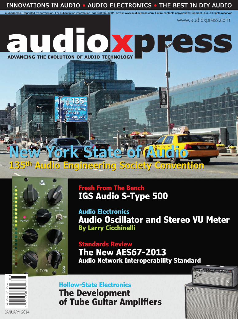
www.audioxpress.com
xpressaudioADVANCING THE EVOLUTION OF AUDIO TECHNOLOGY
www.audioxpress.com
INNOVATIONS IN AUDIO • AUDIO ELECTRONICS • THE BEST IN DIY AUDIO
New York State of Audio135th Audio Engineering Society Convention
Fresh From The BenchIGS Audio S-Type 500Audio ElectronicsAudio Oscillator and Stereo VU MeterBy Larry Cicchinelli
Standards ReviewThe New AES67-2013Audio Network Interoperability Standard
Hollow-State ElectronicsThe Development of Tube Guitar Amplifiers
AU
DIO
XP
RE
SS
| J
AN
UA
RY
20
14
JANUARY 2014
audioXpress. Reprinted by permission. For subscription information, call 800.269.6301, or visit www.audioxpress.com. Entire contents copyright © Segment LLC. All rights reserved.
You Can DIY!
46 | January 2014 | audioxpress.com
ax
Although the Dayton Audio UM12-22 12” Ultimax driver has exceptional linear excursion capability, there is only so much output you can get from one 12” driver at very low frequencies. I have sev-eral CDs with extremely low frequencies that were recorded at high levels.
In particular, I have a CD from the Boston Audio Society with a recording of Camille Saint-Saëns’s Organ Symphony #3, which has very high-level 17-Hz pedal notes at several places in the record-ing. If you attempt to play this at realistic levels with any ordinary speaker, you will surely drive the woofer out of its linear excursion range and pos-sibly cause the voice coil to bottom out. Normally, the solution to this problem would be to reduce the overall levels. However, that will result in a low overall volume that is quite unlike listening to the real performance due to the loss of detail. Note, this is not a case of amplifier clipping.
The acoustical requirement to increase excursion with decreasing frequency to maintain the same
output level creates a mechanical problem as the cone/voice coil assembly moves too far. If you have ever experienced this, you know drivers make a distinctive noise when striking the back plate that is quite unmusical and most disconcerting.
To eliminate the problem, I used the Behringer DEQ2496 high-precision digital 24-bit/96-kHz EQ/RTA mastering processor. This DEQ2496’s function is controlled on three menu pages. The first menu enables you to set the amount of modification you make to the gain and is indicated in tenths of a decibel. The second menu enables you to set the attack and release times and change the trigger point. The third menu enables you to choose the correction mode and parameters.
You can use the DEQ2496 functions to determine several key signal modifiers and set specific levels where action is taken to modify the gain applied to the signal. The control parameters include the adjusted signal’s modified gain level, the threshold where the modification begins, the ratio or rate
By
Thomas Perazella(United States)
Tips to Resurrect a Classic Speaker or Design a New System (Part 3)Utilizing DSP-Based Processors
Photo 1: The DEQ function’s first page details the woofer’s limit over extension at low frequencies and high power.
This third and final segment of the article series on restoring a Heil air motion transformer (AMT)-based speaker details additional problem solving methods that use DSP-based processors. The article also discusses final listening and voicing a speaker.
audioXpress. Reprinted by permission. For subscription information, call 800.269.6301, or visit www.audioxpress.com. Entire contents copyright © Segment LLC. All rights reserved.
REPRINT
REPRINT
REPRINTTips to Resurrect a
REPRINTTips to Resurrect a
Classic Speaker or Design
REPRINTClassic Speaker or Design
a New System
REPRINT
a New System (Part 3)
REPRINT
(Part 3)
REPRINT
Utilizing DSP-Based Processors
REPRINT
Utilizing DSP-Based Processors
Photo 1: The DEQ function’s first page details the woofer’s limit over extension at low frequencies and high power.
REPRINT
Photo 1: The DEQ function’s first page details the woofer’s limit over extension at low frequencies and high power.
This third and final segment of the article series on restoring a Heil air motion
REPRINT
This third and final segment of the article series on restoring a Heil air motion transformer (AMT)-based speaker details additional problem solving methods that use
REPRINT
transformer (AMT)-based speaker details additional problem solving methods that use
REPRINT
Although the Dayton Audio UM12-22 12” Ultimax
REPRINT
Although the Dayton Audio UM12-22 12” Ultimax driver has exceptional linear excursion capability,
REPRINT
driver has exceptional linear excursion capability, there is only so much output you can get from
REPRINT
there is only so much output you can get from one 12” driver at very low frequencies. I have sev
REPRINT
one 12” driver at very low frequencies. I have several CDs with extremely low frequencies that were REPRIN
T
eral CDs with extremely low frequencies that were recorded at high levels. REPRIN
T
recorded at high levels. In particular, I have a CD from the Boston Audio REPRIN
T
In particular, I have a CD from the Boston Audio Society with a recording of Camille Saint-Saëns’s REPRIN
T
Society with a recording of Camille Saint-Saëns’s Organ Symphony #3, which has very high-level REPRIN
T
Organ Symphony #3, which has very high-level 17-Hz pedal notes at several places in the recordREPRIN
T
17-Hz pedal notes at several places in the record
DSP-based processors. The article also discusses final listening and voicing a
REPRINT
DSP-based processors. The article also discusses final listening and voicing a

audioxpress.com | January 2014 | 47
that the change occurs, the time delay after the trigger level occurs for action to be taken (Attack), the time delay after the signal falls back below the threshold for the modification to cease (Release), and the type of action.
Controlling driver excursion is another excellent use of the DEQ function. In this case, I used a high-pass function with a –6-dB gain reduction, a –31-dB threshold level, and a 1:3 ratio (see Photo 1).
Since this iteration of the DEQ function was set for a lower frequency then longer attack and release times could be used. They were 34.86 and 304.2 ms, respectively (see Photo 2).
On menu page three, I selected the L12 mode for the high-pass function with a 12-dB/octave slope. At first, Behringer’s nomenclature is confusing, since we always think of a high- or low-pass filter as having unity gain except for the modified areas, which have their gain lowered. However, in this function, you can decrease or increase the gain.
The nomenclature makes more sense if you think of increasing the gain. In this case, increasing the gain in the lower frequency range would create a “low-pass” device. However, I was lowering the gain in the low frequencies, making the “low-pass” func-tion actually more consistent with generally accepted notions of a high pass.
Still confused? Fortunately, the parameters are graphically represented so what you select is immedi-ately apparent. I chose a 39.9-Hz frequency. Photo 3 shows the resulting correction.
Testing after I implemented this DEQ function resulted in a normal listening level for the “Organ Symphony #3,” with no ugly noises coming from the woofer during the passages with the heavy pedal notes. The audible improvements this function makes are substantial, enabling you to enjoy the music with-out annoying distractions. Although the real answer to accurately reproducing these types of recordings requires several drivers and a lot of amplifier power, I find the ability to use normal speakers and ampli-fiers to achieve most of what the music contains astounding. You have to hear the results to believe it. You do make compromises, but they are a fraction of what you would have to do without DEQ.
Voicing the SpeakerFor the sake of this project, I stretched the tra-
ditional definition of speaker voicing to encompass adjustments that affected many segments of the chain. The common definition of speaker voicing cov-ers crossover points, crossover slopes, and drive lev-els to individual drivers. Box size, speaker position-ing, and baffle shapes are also part of the equation.
I have been asked several times why you have to
voice a speaker. Many people think when they pur-chase a speaker the manufacture has already done that job. If you build your own speakers and you chose drivers that are flat, you may think you only have to adjust drive levels and crossover points.
Unfortunately, neither of these statements is true. First, I have never seen drivers with totally flat response. Second, radiation pattern differences will affect the final balance at the listening posi-tion. Third, microphone frequency, pattern differ-ences, and their placement during the recording have major effects on the sound. Fourth, master-ing decisions can vastly affect tonal balance. Fifth, speaker placements in the room and room effects also have major impacts on the final sound.
One of the easiest ways to demonstrate how microphone choices affect the final sound is to play track 5 of the first Stereophile test CD. J. Gordon Holt, Stereophile’s founder, sat at a desk and read one of his articles into 18 different microphones, one at a time. He did not change anything else in the recording or subsequent processing between the sections recorded with different microphones. You will find it difficult to believe it is the same per-son speaking. The differences are dramatic. If just the microphone choice makes such a difference, imagine what some of the other factors can do to the resulting sound. You can either ignore the dif-ferences or try to compensate for them.
It is important to remember that if the recording process significantly modifies the original sound,
Photo 2: The DEQ function’s second page provides input screens showing the attack and release times.
Photo 3: The DEQ function’s third page numerically and graphically shows the mode employed and slope with the turnover frequency.
audioXpress. Reprinted by permission. For subscription information, call 800.269.6301, or visit www.audioxpress.com. Entire contents copyright © Segment LLC. All rights reserved.
REPRINT
REPRINT
REPRINT
REPRINT
REPRINT
Still confused? Fortunately, the parameters are
REPRINT
Still confused? Fortunately, the parameters are graphically represented so what you select is immedi
REPRINT
graphically represented so what you select is immedi-
REPRINT
-ately apparent. I chose a 39.9-Hz frequency.
REPRINT
ately apparent. I chose a 39.9-Hz frequency. Photo 3
REPRINT
Photo 3
Testing after I implemented this DEQ function
REPRINT
Testing after I implemented this DEQ function resulted in a normal listening level for the “Organ
REPRINT
resulted in a normal listening level for the “Organ Symphony #3,” with no ugly noises coming from the
REPRINT
Symphony #3,” with no ugly noises coming from the woofer during the passages with the heavy pedal
REPRINT
woofer during the passages with the heavy pedal notes. The audible improvements this function makes
REPRINT
notes. The audible improvements this function makes are substantial, enabling you to enjoy the music with
REPRINT
are substantial, enabling you to enjoy the music with-
REPRINT
-out annoying distractions. Although the real answer
REPRINT
out annoying distractions. Although the real answer to accurately reproducing these types of recordings REPRIN
T
to accurately reproducing these types of recordings requires several drivers and a lot of amplifier power, REPRIN
T
requires several drivers and a lot of amplifier power, I find the ability to use normal speakers and ampliREPRIN
T
I find the ability to use normal speakers and amplifiers to achieve most of what the music contains REPRIN
T
fiers to achieve most of what the music contains astounding. You have to hear the results to believe REPRIN
T
astounding. You have to hear the results to believe it. You do make compromises, but they are a fraction REPRIN
T
it. You do make compromises, but they are a fraction of what you would have to do without DEQ.REPRIN
T
of what you would have to do without DEQ.
voice a speaker. Many people think when they pur
REPRINT
voice a speaker. Many people think when they purchase a speaker the manufacture has already done
REPRINT
chase a speaker the manufacture has already done that job. If you build your own speakers and you
REPRINT
that job. If you build your own speakers and you chose drivers that are flat, you may think you only
REPRINT
chose drivers that are flat, you may think you only have to adjust drive levels and crossover points.
REPRINT
have to adjust drive levels and crossover points. Unfortunately, neither of these statements is
REPRINT
Unfortunately, neither of these statements is true. First, I have never seen drivers with totally
REPRINT
true. First, I have never seen drivers with totally flat response. Second, radiation pattern differences
REPRINT
flat response. Second, radiation pattern differences will affect the final balance at the listening posi
REPRINT
will affect the final balance at the listening position. Third, microphone frequency, pattern differ
REPRINT
tion. Third, microphone frequency, pattern differences, and their placement during the recording
REPRINT
ences, and their placement during the recording have major effects on the sound. Fourth, master
REPRINT
have major effects on the sound. Fourth, master
Photo 2: The DEQ function’s second page provides input screens showing the attack
REPRINT
Photo 2: The DEQ function’s second page provides input screens showing the attack
Photo 3: The DEQ function’s third page numerically and graphically shows the mode
REPRINT
Photo 3: The DEQ function’s third page numerically and graphically shows the mode employed and slope with the turnover frequency.
REPRINT
employed and slope with the turnover frequency.

You Can DIY!
48 | January 2014 | audioxpress.com
ax
there is no practical way to entirely retrieve the original. What you can do is make the resulting sound more to your liking.
I began the voicing process by trying to get the speaker as flat as possible on axis with quasi-anechoic testing. Then, I made adjustments to the balance at the listening position. In the second phase, some of the adjustments begin to correct for room and radiation pattern effects.
A common trap when voicing a speaker is to try to eliminate all room effects. It is just not possible. One of the worst problems is cancellations at certain
narrow and sharp frequency bands. They are caused by energy at that frequency, reflecting off multi-ple surfaces. This results in the combinations of reflections being out of phase, causing a drop in levels. As you put more energy into the problem frequency, the reflected energy from various sur-faces gets equally greater and the cancellations still occur. When you do this, you also throw the balance off for all the other non-canceling positions in the listening area. Probably the best way to avoid this situation is to move the speakers or the listening position and to judiciously use room treatments.
During the speaker voicing process use a flexi-ble, low-distortion, wide-dynamic range equalizer. Prior to digital signal processing high-quality equal-izers were expensive. Now, it is possible to get a digital equalizer that offers more flexibility than ever at prices that are within almost every budget range. In addition to equalization, some of them also include signal generators, real-time analyzers, compressors, limiters, dynamic EQ, and more. For years, I have been using Behringer equalizers with great success in all my systems. With this project, I used the Behringer DEQ2496 mentioned earlier.
I used Liberty Instruments’s application Liberty Audiosuite (LAUD) for PCs during the first phase in which quasi-anechoic measurements are made. An ACO Pacific 7012 microphone capsule feeding a model 4012 preamplifier and a PS9200 power sup-ply/interface provided the input. To protect the PC, I fed output from the microphone interface through a custom interface I built and described in Speaker Builder (see Resources).
The measurement configuration consisted of one channel with the microphone located 1 m from the speaker on axis at a 44” height (i.e., approximately ear level when seated). Using a tri-amped setup with an electronic crossover enables you to easily switch from measuring the overall speaker to separately measuring each driver by using the mute buttons on the crossover for the appropriate channels.
Using the Behringer DSC2496 Ultra Drive crossover, I selected a 24-dB/octave slope and revised 176- and 1,500-Hz crossover points. Next, I took a measurement of the complete speaker with no EQ. Note that these measurements are raw with no smoothing. Figure 1 shows the results. The responses when using the 24- and 48-dB slopes were similar but a 12-dB slope showed a greater suckout in the mid- to high-inter-face region and was somewhat rougher.
The steep slopes of a 24- and 48-dB/octave iter-ation are more effective at eliminating interference between drivers located at different positions. When using a 12-dB/octave slope, there is more overlap between drivers with resulting cancellations and
Figure 1: The completed speaker’s quasi-anechoic response is shown after the appropriate drive levels were set with 24-dB/octave slopes, but before any EQ was done.
Photo 4: The final Parametric EQ in data form was applied to the completed speaker to achieve the flattest quasi-anechoic response.
Photo 5: This is the final Parametric EQ in graphical form that was applied to the completed speaker to achieve the flattest quasi-anechoic response.
audioXpress. Reprinted by permission. For subscription information, call 800.269.6301, or visit www.audioxpress.com. Entire contents copyright © Segment LLC. All rights reserved.
REPRINT
REPRINT
REPRINT
there is no practical way to entirely retrieve the
REPRINT
there is no practical way to entirely retrieve the original. What you can do is make the resulting
REPRINT
original. What you can do is make the resulting
I began the voicing process by trying to get the
REPRINT
I began the voicing process by trying to get the speaker as flat as possible on axis with quasi-anechoic
REPRINT
speaker as flat as possible on axis with quasi-anechoic testing. Then, I made adjustments to the balance
REPRINT
testing. Then, I made adjustments to the balance at the listening position. In the second phase, some
REPRINT
at the listening position. In the second phase, some of the adjustments begin to correct for room and
REPRINT
of the adjustments begin to correct for room and radiation pattern effects.
REPRINT
radiation pattern effects. A common trap when voicing a speaker is to try
REPRINT
A common trap when voicing a speaker is to try to eliminate all room effects. It is just not possible.
REPRINT
to eliminate all room effects. It is just not possible. One of the worst problems is cancellations at certain
REPRINT
One of the worst problems is cancellations at certain
occur. When you do this, you also throw the balance
REPRINT
occur. When you do this, you also throw the balance off for all the other non-canceling positions in the
REPRINT
off for all the other non-canceling positions in the listening area. Probably the best way to avoid this
REPRINT
listening area. Probably the best way to avoid this situation is to move the speakers or the listening
REPRINTsituation is to move the speakers or the listening
position and to judiciously use room treatments.
REPRINTposition and to judiciously use room treatments.
During the speaker voicing process use a flexi
REPRINTDuring the speaker voicing process use a flexi
ble, low-distortion, wide-dynamic range equalizer.
REPRINTble, low-distortion, wide-dynamic range equalizer.
Prior to digital signal processing high-quality equal
REPRINTPrior to digital signal processing high-quality equal
izers were expensive. Now, it is possible to get a
REPRINTizers were expensive. Now, it is possible to get a
digital equalizer that offers more flexibility than
REPRINTdigital equalizer that offers more flexibility than
ever at prices that are within almost every budget
REPRINT
ever at prices that are within almost every budget range. In addition to equalization, some of them
REPRINT
range. In addition to equalization, some of them also include signal generators, real-time analyzers,
REPRINT
also include signal generators, real-time analyzers, compressors, limiters, dynamic EQ, and more. For
REPRINT
compressors, limiters, dynamic EQ, and more. For years, I have been using Behringer equalizers with
REPRINT
years, I have been using Behringer equalizers with great success in all my systems. With this project,
REPRINT
great success in all my systems. With this project, I used the Behringer DEQ2496 mentioned earlier.
REPRINT
I used the Behringer DEQ2496 mentioned earlier.
REPRINT
I used Liberty Instruments’s application Liberty
REPRINT
I used Liberty Instruments’s application Liberty Audiosuite (LAUD) for PCs during the first phase
REPRINT
Audiosuite (LAUD) for PCs during the first phase
REPRINT
REPRINT
REPRINT
Photo 4: The final Parametric EQ in data form was applied to the completed speaker to REPRINT
Photo 4: The final Parametric EQ in data form was applied to the completed speaker to achieve the flattest quasi-anechoic response.REPRIN
T
achieve the flattest quasi-anechoic response.REPRINT

audioxpress.com | January 2014 | 49
reinforcements at different positions as you move along the axis between drivers.
Next, I used the DEQ2496 to correct the frequency response. The digital electronic equalizer provides the option to use several parametric EQ channels. Being able to break away from fixed graphic type effects enables you to make finer adjustments across the entire frequency range.
For this exercise, I used the DEQ2496’s 10 paramet-ric bands to produce a fairly flat curve. Photo 4 shows the actual applied corrections in data form. Photo 5 shows the same EQ in graphical form. The curve‘s complex shape is apparent and would be extremely difficult if not impossible to achieve using passive crossover components or a standard graphic equal-izer. If you look at each section’s bandwidth values, you will notice they vary and are fairly broad from 0.5 to 2 octaves. This type of overlap enables you to generate a complex curve.
Overall, the equalized response at 24 dB/octave is fairly flat from the lower measurement limit of about 300 Hz to 20 kHz. Figure 2 shows the exception, with two suckouts around 12 kHz and 15 kHz. They appear to be cavity resonances due to the Heil AMT’s construc-tion. I was able to slightly reduce the effect, but with suckouts that result from cancellations, you cannot totally remove them with more drive.
As with room problems, if you increase the drive at a suckout frequency, the higher output reflected from the housing’s offending sections increase proportion-ately and continue to produce cancellations. The only solution is to change the physical construction that caused the interfering reflections or to add absorptive material. I added damping material inside the AMT housing but it had a limited effect. It is interesting to note the current AMT’s housing has a more open design and some of the cavities have been eliminated, possibly eliminating this suckout.
Earlier, I mentioned the Eton midrange had some response irregularities as its frequency increased. Figure 3 shows the driver’s raw response when mounted in free air. Between 2,500 and 5,000 Hz, there is a significant ragged peak. It appears to be the reflected energy from the basket, which will not only change the timbre but also cause congestion. Figure 4 shows the comparison with the same driver on the baffle with the 24-dB/octave crossover slope and the speaker’s final EQ applied. The major prob-lem in the 2.5-to-5-kHz region effectively disappears. You would not be able to achieve that result with a shallow slope in your crossover.
Music CurvesFinally, I produced a set of curves that would
compensate for some of the worst deviations found
in the recording/mastering process. In theory, you could produce a separate compensating curve for every cut on every record but you would quickly go crazy in the process. I have found that producing about five to 10 curves will suit the vast majority of recordings.
To test the speakers, I have a group of musi-cal test recordings that I have used for years. Recently, I added several new selections to that list as they became available. To streamline the process, I burned four CDs with the individual tracks I wanted. The CDs included pop, rock, jazz, classi-cal, and country selections. Some of the music also contained sounds designed to determine transient
Figure 2: The completed speaker’s quasi-anechoic response is shown after the appropriate drive levels were set with 24-dB/octave slopes with the final parametric EQ.
Figure 3: The quasi-anechoic response of the Eton driven full range with no EQ shows a ragged peak between 2,500 and 5,000 Hz.
audioXpress. Reprinted by permission. For subscription information, call 800.269.6301, or visit www.audioxpress.com. Entire contents copyright © Segment LLC. All rights reserved.
REPRINT
As with room problems, if you increase the drive at
REPRINT
As with room problems, if you increase the drive at a suckout frequency, the higher output reflected from
REPRINT
a suckout frequency, the higher output reflected from the housing’s offending sections increase proportion
REPRINT
the housing’s offending sections increase proportion-
REPRINT
-ately and continue to produce cancellations. The only
REPRINT
ately and continue to produce cancellations. The only solution is to change the physical construction that
REPRINT
solution is to change the physical construction that caused the interfering reflections or to add absorptive
REPRINT
caused the interfering reflections or to add absorptive material. I added damping material inside the AMT
REPRINT
material. I added damping material inside the AMT housing but it had a limited effect. It is interesting
REPRINT
housing but it had a limited effect. It is interesting to note the current AMT’s housing has a more open
REPRINT
to note the current AMT’s housing has a more open design and some of the cavities have been eliminated,
REPRINT
design and some of the cavities have been eliminated, possibly eliminating this suckout.
REPRINT
possibly eliminating this suckout.Earlier, I mentioned the Eton midrange had some REPRIN
T
Earlier, I mentioned the Eton midrange had some response irregularities as its frequency increased. REPRIN
T
response irregularities as its frequency increased. shows the driver’s raw response when REPRIN
T
shows the driver’s raw response when mounted in free air. Between 2,500 and 5,000 Hz, REPRIN
T
mounted in free air. Between 2,500 and 5,000 Hz, there is a significant ragged peak. It appears to be REPRIN
T
there is a significant ragged peak. It appears to be the reflected energy from the basket, which will not REPRIN
T
the reflected energy from the basket, which will not only change the timbre but also cause congestion. REPRIN
T
only change the timbre but also cause congestion.
in the recording/mastering process. In theory, you
REPRINT
in the recording/mastering process. In theory, you could produce a separate compensating curve for
REPRINT
could produce a separate compensating curve for every cut on every record but you would quickly go
REPRINT
every cut on every record but you would quickly go crazy in the process. I have found that producing
REPRINT
crazy in the process. I have found that producing about five to 10 curves will suit the vast majority
REPRINT
about five to 10 curves will suit the vast majority of recordings.
REPRINT
of recordings.To test the speakers, I have a group of musi
REPRINT
To test the speakers, I have a group of musical test recordings that I have used for years.
REPRINT
cal test recordings that I have used for years. Recently, I added several new selections to that
REPRINT
Recently, I added several new selections to that list as they became available. To streamline the
REPRINT
list as they became available. To streamline the process, I burned four CDs with the individual tracks
REPRINT
process, I burned four CDs with the individual tracks I wanted. The CDs included pop, rock, jazz, classi
REPRINT
I wanted. The CDs included pop, rock, jazz, classical, and country selections. Some of the music also
REPRINT
cal, and country selections. Some of the music also contained sounds designed to determine transient
REPRINT
contained sounds designed to determine transient
REPRINT
REPRINT
REPRINT
REPRINT

You Can DIY!
50 | January 2014 | audioxpress.com
ax
response, dynamic range, frequency range, sound stage and depth, and definition.
When implementing listening tests, you can improve your results and make the process eas-ier by finding the correct playback level for each track before it is seriously auditioned. If the level is too low, subtle details will be lost. If it is too loud, it will sound unnatural regardless of set-tings. I ran through each track with the base EQ, determined what I felt were the correct levels, and recorded them in a reference spreadsheet. I later used that sheet to record the final correc-tion curve and relevant information on the piece. Inevitably when conducting listening tests with others, I always get questions about the music selections. The spreadsheet is an easy way to answer the questions and eliminate time looking for background information.
A few of the local audio club’s members took
part in the listening. Individual musical tastes dif-fer, but sometimes you can ferret out a problem that all people recognize. In this test, I used the DCX2496 connected to my laptop to switch between different crossover slopes—while keeping all other parameters the same. The listeners determined that 48 dB/octave was not optimal. This surprised me because in my main system the 48-dB slope is clearly superior. It provides the greatest clarity, stage size, and smoothness. My only guess is that the controlled and consistent radiation patterns of that system’s drivers lend themselves to the higher slopes.
The 24-dB/octave slope worked well. However, the 12 dB/octave had some serious shortcomings. One of the most noticeable characteristics was a shrinking of the sound stage as the slopes decreased. At the 12 dB/octave, there was a considerable reduction in the soundstage’s width and depth as well as a loss of detail. I decided to stay with the 24-dB/octave slope. The 176- and 1,500-Hz crossover frequencies eliminated some of the earlier problems I noticed, so they remained.
One of the Behringer DEQ2496’s great advan-tages is a function called “Virtual Paragraphic Equal-izer” (VPQ). The function enables you to adjust the effective Q or bandwidth of each individual fre-quency in the graphic equalizer from a default one-third octave to 59/3 octave in two-third octave steps, which represents one-third octave on both sides of the center frequency.
By adjusting the bandwidth to a range around 3 octaves as a start, you can move the EQ’s cen-ter frequency up or down with a simple one knob adjustment while listening to the music. The function enables you to rapidly locate the center frequency of the problem compared to the stark effects cre-ated by gross high Q adjustments, which can be misleading. For example, if you have a sound that is too forward in the presence region, you can start with a 3-dB cut at a center frequency around 3 kHz and use a bandwidth of 3 (see Photo 6).
By adjusting one knob, you can move it back and forth in one-third octave increments until you find the spot that sounds best (e.g., 2 kHz). I did this sev-eral times with different pieces and created curves that seemed like reasonable compromises for each of them. Naming them for the problems they cor-rected (e.g., Pop Bright, Presence, Honky, etc.) made them easy to remember. Once you save them, you can simply turn one knob on the equalizer to recall all your adjustments. Then, you are ready to have a more pleasurable listening experience.
When you use an equalizer to make compen-sating curves, resist the temptation to use a lot
About the AuthorThomas Perazella is a retired IT director. He is a member of the Audio Engineering Society, the Boston Audio Society, and the DC Audio DIY group. He has authored several articles in professional audio journals.
Figure 4: The Eton’s quasi-anechoic response with 24-dB/octave shows crossover slopes at 176 and 1,500 Hz with compensating EQ.
Photo 6: The Virtual Paragraphic Equalizer function permits you to set almost any bandwidth for an equalizer correction. It also enables you to move up and down the frequency scale using a single knob, while retaining that same bandwidth and levels with the test music playing.
audioXpress. Reprinted by permission. For subscription information, call 800.269.6301, or visit www.audioxpress.com. Entire contents copyright © Segment LLC. All rights reserved.
REPRINT
response, dynamic range, frequency range, sound
REPRINT
response, dynamic range, frequency range, sound stage and depth, and definition.
REPRINT
stage and depth, and definition.When implementing listening tests, you can
REPRINT
When implementing listening tests, you can improve your results and make the process eas
REPRINT
improve your results and make the process eas-
REPRINT
-ier by finding the correct playback level for each
REPRINT
ier by finding the correct playback level for each ack before it is seriously auditioned. If the level
REPRINT
ack before it is seriously auditioned. If the level is too low, subtle details will be lost. If it is too
REPRINT
is too low, subtle details will be lost. If it is too loud, it will sound unnatural regardless of set
REPRINT
loud, it will sound unnatural regardless of settings. I ran through each track with the base EQ,
REPRINT
tings. I ran through each track with the base EQ, dete
REPRINT
determ
REPRINT
rmined what I felt were the correct levels,
REPRINT
ined what I felt were the correct levels, and recorded them in a reference spreadsheet. I
REPRINT
and recorded them in a reference spreadsheet. I later used that sheet to record the final correc
REPRINT
later used that sheet to record the final correction curve and relevant information on the piece.
REPRINT
tion curve and relevant information on the piece. I
REPRINT
Ine
REPRINT
nevitably when conducting listening tests with
REPRINT
vitably when conducting listening tests with others, I always get questions about the music
REPRINT
others, I always get questions about the music selections. The spreadsheet is an easy way to REPRIN
T
selections. The spreadsheet is an easy way to answer the questions and eliminate time looking REPRIN
T
answer the questions and eliminate time looking for background information.REPRIN
T
for background information.A few of the local audio club’s members took REPRIN
T
A few of the local audio club’s members took
me because in my main system the 48-dB slope
REPRINT
me because in my main system the 48-dB slope is clearly superior. It provides the greatest clarity,
REPRINT
is clearly superior. It provides the greatest clarity, stage size, and smoothness. My only guess is that
REPRINT
stage size, and smoothness. My only guess is that the controlled and consistent radiation patterns of
REPRINTthe controlled and consistent radiation patterns of
that system’s drivers lend themselves to the higher
REPRINTthat system’s drivers lend themselves to the higher
slopes.
REPRINTslopes.
The 24-dB/octave slope worked well. However, the
REPRINTThe 24-dB/octave slope worked well. However, the
12 dB/octave had some serious shortcomings. One of
REPRINT12 dB/octave had some serious shortcomings. One of
the most noticeable characteristics was a shrinking
REPRINTthe most noticeable characteristics was a shrinking
of the sound stage as the slopes decreased. At the
REPRINTof the sound stage as the slopes decreased. At the
12 dB/octave, there was a considerable reduction in
REPRINT
12 dB/octave, there was a considerable reduction in the soundstage’s width and depth as well as a loss
REPRINT
the soundstage’s width and depth as well as a loss of detail. I decided to stay with the 24-dB/octave
REPRINT
of detail. I decided to stay with the 24-dB/octave slope. The 176- and 1,500-Hz crossover frequencies
REPRINT
slope. The 176- and 1,500-Hz crossover frequencies eliminated some of the earlier problems I noticed,
REPRINT
eliminated some of the earlier problems I noticed, so they remained.
REPRINT
so they remained.One of the Behringer DEQ2496’s great advan
REPRINT
One of the Behringer DEQ2496’s great advantages is a function called “Virtual Paragraphic Equal
REPRINT
tages is a function called “Virtual Paragraphic Equalizer” (VPQ). The function enables you to adjust the
REPRINT
izer” (VPQ). The function enables you to adjust the
REPRINT
Boston Audio Society, and
REPRINT
Boston Audio Society, and the DC Audio DIY group.
REPRINT
the DC Audio DIY group. He has authored several
REPRINT
He has authored several articles in professional
REPRINT
articles in professional audio journals. REPRIN
T
audio journals. REPRINT
REPRINT
Figure 4: The Eton’s quasi-anechoic response with 24-dB/octave shows crossover slopes at
REPRINT
Figure 4: The Eton’s quasi-anechoic response with 24-dB/octave shows crossover slopes at
REPRINT
REPRINT
REPRINT

audioxpress.com | January 2014 | 51
ResourcesT. Perazella, “Interface for LAUD Measurement System,” Speaker Builder, 1999.
C. Saint Saëns, “Organ Symphony 3,” Boston Audio Society, Test CD-1, Track 3.
Stereophile, “Why Experts Disagree,” Test CD 1, Track 5, http://ssl.blueearth.net/primedia/product.php?productid=2&cat=0&bestseller=Y.
Sources7012 microphone capsule, 4012 preamplifier, and PS9200 power supply/interfaceACO Pacific, Inc. | www.acopacific.com
ULTRA-DRIVE PRO DCX2496 digital loudspeaker management system and DEQ2496 processorBehringer | www.behringer.com
UM12-22 Ultimax DVC subwooferDayton Audio | www.daytonaudio.com
Liberty Audiosuite (LAUD) audio measurement and analysis system for PCsLiberty Instruments, Inc. | www.libinst.com
of narrow corrections or corrections that exceed more than a few decibels. The goal is to eliminate gross problems while maintaining a realistic sound. The smoother you make the corrections the better the resulting sound. Much of the music I listen to sounds good with the basic setting, but it is helpful to correct some of the less than great recordings of music that moves me.
Final ImpressionsIn a nutshell, was the project successful? I
believe it was. The sound is dynamic, wide and flat in frequency response, low in distortion, and provides sound stage width and depth. Transients are exceptionally good, adding to the sense of real-ism. Even with the basic design’s limitation—using one driver for each of three frequency ranges—the addition of the new woofer plus the application of corrections provided by the digital equalizer and crossover improved the sound quality when com-pared to the original version.
Will this replace my primary system with huge line arrays that have the same radiation pattern and large amounts of linear volume displacement?
No way! But, if I had size and cost restrictions, I could easily live with these resurrected Heil-based speakers. Long live DSP! ax
Analog Class-D Amplifiers
Activate your loudspeakers with Anaview!
SWEDEN | USA | HONG KONG | WWW.ANAVIEW.COMAnaview is a member of the ETAL Group, AB
• On-board Power Supply • Robust Design with
Advanced Protection• Compact & Efficient
• Stby & Aux Voltages• Easy to Integrate• Award Winning Sound• UL Certified
Anaview’s Class-D amplifiers are available to discriminating OEMs looking for premium sound and audio performance.
audioXpress. Reprinted by permission. For subscription information, call 800.269.6301, or visit www.audioxpress.com. Entire contents copyright © Segment LLC. All rights reserved.
REPRINT
REPRINT
C. Saint Saëns, “Organ Symphony 3,” Boston Audio Society, Test CD-1, Track 3.
REPRINT
C. Saint Saëns, “Organ Symphony 3,” Boston Audio Society, Test CD-1, Track 3.
“Why Experts Disagree,” Test CD 1, Track 5, http://ssl.blueearth.net/
REPRINT
“Why Experts Disagree,” Test CD 1, Track 5, http://ssl.blueearth.net/primedia/product.php?productid=2&cat=0&bestseller=Y.
REPRINTprimedia/product.php?productid=2&cat=0&bestseller=Y.
7012 microphone capsule, 4012 preamplifier, and PS9200 power supply/
REPRINT7012 microphone capsule, 4012 preamplifier, and PS9200 power supply/
ACO Pacific, Inc. | www.acopacific.com
REPRINTACO Pacific, Inc. | www.acopacific.com
ULTRA-DRIVE PRO DCX2496 digital loudspeaker management system and
REPRINTULTRA-DRIVE PRO DCX2496 digital loudspeaker management system and
Behringer | www.behringer.com
REPRINT
Behringer | www.behringer.com
UM12-22 Ultimax DVC subwoofer
REPRINT
UM12-22 Ultimax DVC subwooferDayton Audio | www.daytonaudio.com
REPRINT
Dayton Audio | www.daytonaudio.com
Liberty Audiosuite (
REPRINT
Liberty Audiosuite (LAUD
REPRINT
LAUD) audio measurement and analysis system for PCs
REPRINT
) audio measurement and analysis system for PCsLiberty Instruments, Inc. | www.libinst.com
REPRINT
Liberty Instruments, Inc. | www.libinst.com
REPRINT
REPRINT
REPRINT
Analog Class-D Amplifiers
REPRINT
Analog Class-D Amplifiers
Anaview’s Class-D amplifiers are available to REPRINT
Anaview’s Class-D amplifiers are available to discriminating OEMs looking for premium sound REPRIN
T
discriminating OEMs looking for premium sound and audio performance. REPRIN
T
and audio performance. REPRINT
REPRINT

off an audioxpress membership
audioxpress.com/reprint25J O I N T O D A Y !
audioaudioaudioacoustics
audioXpress has been serving up the best in DIY audio for more
than a decade! With an increased focus on professional
audio, acoustics, and audio electronics, audioXpress is
expanding its coverage and content to better serve audiophiles
worldwide. Become a member and gain instant access to
design tips, product reviews, and industry insight.