august 2005 - hcfcd · august 2005 approved by commissioners court 10/25/05 2005 standard...
TRANSCRIPT
August 2005Approved by Commissioners Court 10/25/05
2005Standard Specifications
andDetail Sheets
9900 Northwest FreewayHouston, Texas 77092
713-684-4000www.hcfcd.org

HARRIS COUNTY FLOOD CONTROL DISTRICT STANDARD SPECIFICATIONS BOOK
TABLE OF CONTENTS
8/31/2005 Harris County Flood Control District Standard Specifications 1/2 Table of Contents
DIVISION 1 – GENERAL REQUIREMENTS
SUMMARY 01181 Private Utilities
PRICE AND PAYMENT PROCEDURES
01270 Measurement and Payment 01292 Schedule of Values
ADMINISTRATIVE REQUIREMENTS
01325 Construction Schedules 01328 Construction Surveying 01330 Submittal Procedures
QUALITY REQUIREMENTS
01422 Reference Technical Standards 01457 Construction Tests and Inspection
TEMPORARY FACILITIES AND CONTROLS
01520 Temporary Facilities for Engineer 01562 Construction Fence 01565 General Source Controls 01580 Project Signs
EXECUTION REQUIREMENTS
01785 Project Record Documents DIVISION 2 – SITE CONSTRUCTION
SITE PREPARATION 02120 Material Disposal 02200 Site Preparation and Restoration 02232 Selective Clearing 02233 Clearing and Grubbing 02241 Care and Control of Water 02269 Trench Safety System
EARTHWORK
02314 Fill Material 02315 Excavating and Backfilling 02316 Structural Excavating and Backfilling

HARRIS COUNTY FLOOD CONTROL DISTRICT STANDARD SPECIFICATIONS BOOK
TABLE OF CONTENTS
8/31/2005 Harris County Flood Control District Standard Specifications 2/2 Table of Contents
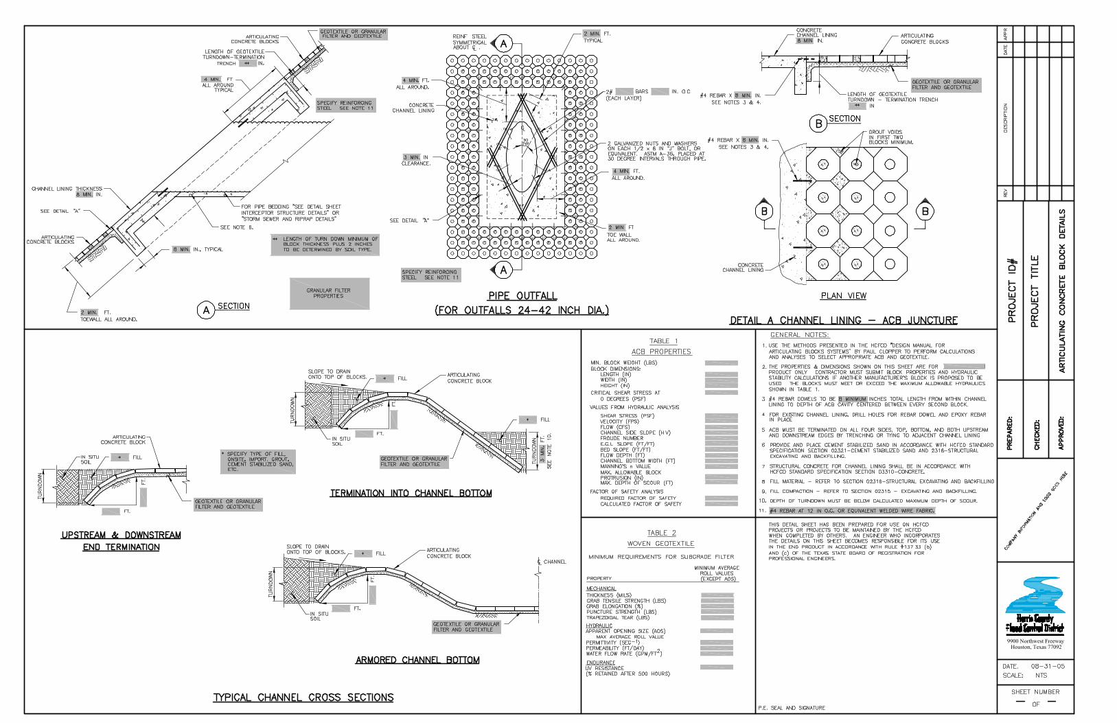
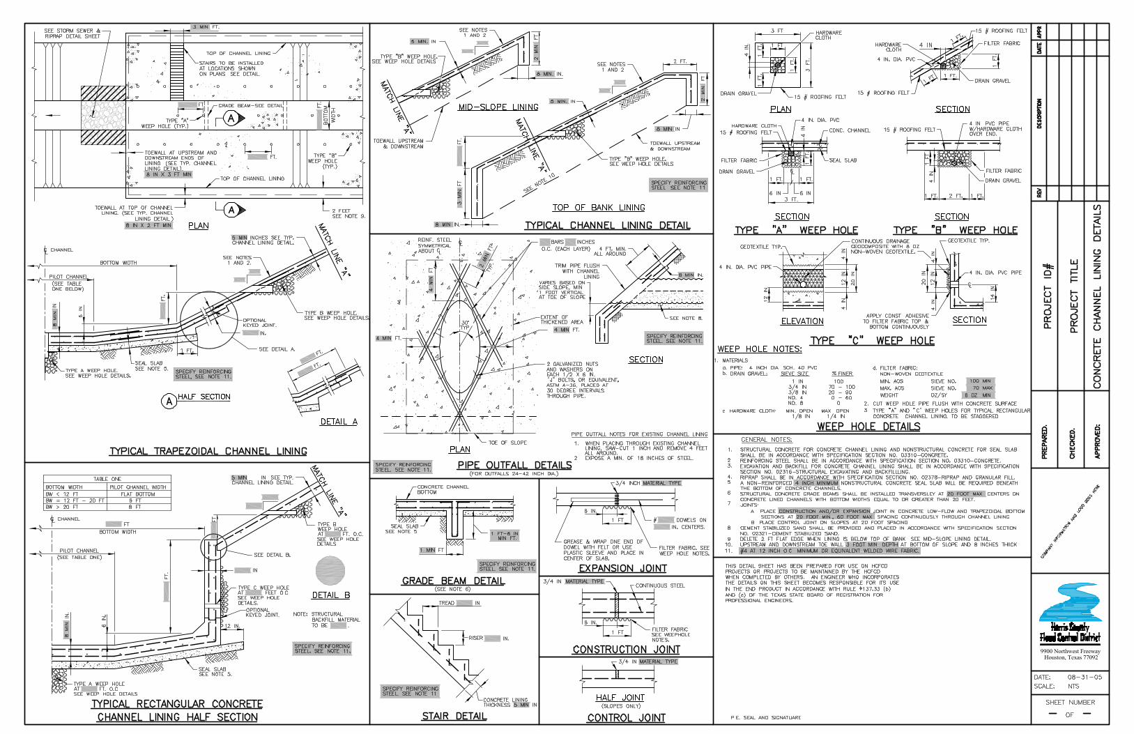
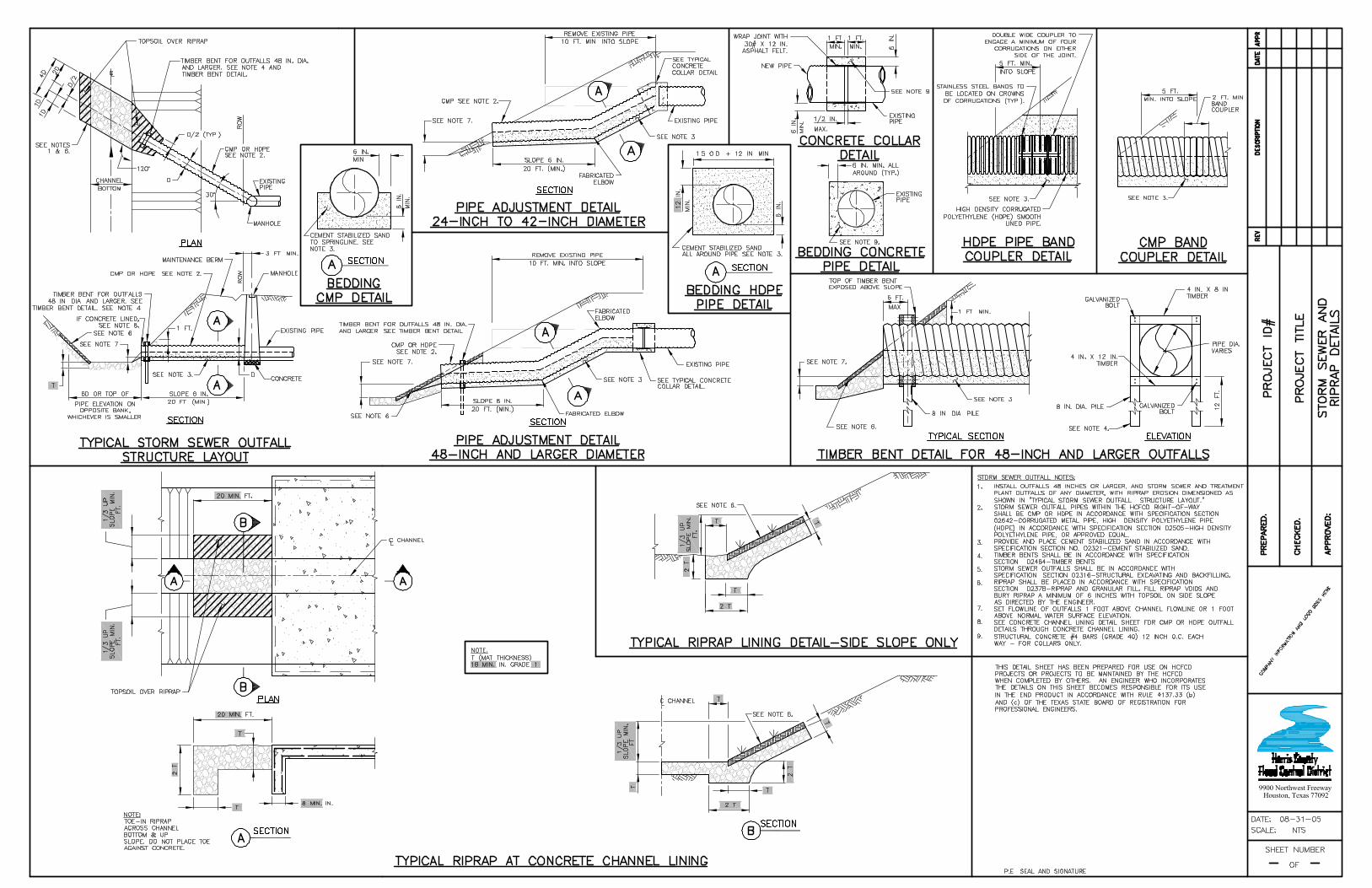
EARTHWORK (CONTINUED) 02317 Desilting Channels 02321 Cement Stabilized Sand 02322 Flowable Fill 02361 Silt Fences 02364 Filter Dams 02365 Stabilized Construction Access 02374 Articulating Concrete Block 02376 Concrete Channel Lining and Concrete Interceptor Structures 02377 Rectangular Concrete Channel 02378 Riprap and Granular Fill 02379 Geotextiles for Erosion Control Systems
FOUNDATION AND LOAD-BEARING ELEMENTS
02462 Steel Sheet Piling 02464 Timber Bents
DRAINAGE AND CONTAINMENT
02505 High Density Polyethylene Pipe 02611 Reinforced Concrete Pipe 02612 Precast Reinforced Concrete Box 02630 Concrete Manholes 02631 Storm Sewers and Outfalls 02632 Cast-in-Place Inlets, Headwalls and Wingwalls 02642 Corrugated Metal Pipe
PLANTING
02911 Topsoil 02921 Turf Establishment 02922 Sod 02923 Seed 02925 Mulch and Tackifier 02936 Fertilizer 02938 Mowing 02940 Irrigation 02941 Herbicide Application
DIVISION 3 – CONCRETE
CAST-IN-PLACE CONCRETE 03310 Concrete
DETAIL SHEETS

8/31/2005 Harris County Flood Control District Standard Specifications 01181 - 1/1 Private Utilities
SECTION 01181
PRIVATE UTILITIES
PART 1 – GENERAL 1.1 SUMMARY
A. Section includes requirements for areas of work involving private utility companies including, but not limited to the following: 1. Telephone Companies. 2. Gas Companies. 3. Power (Electric) Companies. 4. Cable Television Companies. 5. Pipeline Companies.
1.2 NOTIFICATIONS
A. Notify private utilities of proposed work at least 48 hours prior to starting work at site.
B. The following organizations provide construction notification services for member companies: 1. Utility Coordinating Committee for the
Houston Metropolitan Area Lone Star Notification Center 713-223-4567 (in Houston) 1-800-669-8344 (outside of Houston)
2. Texas One Call System 1-800-245-4545
3. DIG-TESS 11880 Greenville Ave., Suite 120 Dallas, Texas 75243 1-800-344-8377
1.3 UTILITY RELOCATIONS
A. Where relocation of utility work is necessary for construction purposes, coordinate the relocations with the Harris County Flood Control District Utility Coordinator (713-316-4801) prior to start of work.
PART 2 – PRODUCTS – Not used PART 3 – EXECUTION – Not used
END OF SECTION

8/31/2005 Harris County Flood Control District Standard Specifications 01270 - 1/3 Measurement and Payment
SECTION 01270
MEASUREMENT AND PAYMENT
PART 1 – GENERAL 1.1 SUMMARY
A. Section includes requirements for measurement and payment procedures, conditions for nonconformance assessment and nonpayment for rejected products.
1.2 MEASUREMENT
A. Measurement methods delineated in individual Sections are intended to complement the criteria of this Section. In the event of conflict, the requirements of the individual Section governs.
B. Take measurements and compute quantities accordingly. C. Provide equipment, workers and survey personnel as necessary to perform
the measurement. 1.3 UNIT QUANTITIES
A. Quantity and measurement estimates stated on the Unit Price Schedule are for contract purposes only.
B. If greater or lesser quantities are required than those quantities indicated in the Unit Price Schedule, provide the required quantities at the unit prices contracted.
C. Measurement by Volume: Measure by cubic dimension. D. Measurement by Area: Measure by square dimension. E. Linear Measurement: Measure by linear dimension, at the item centerline
or mean chord. F. Unit Price Measurement: Measure by unit designated on the Unit Price
Schedule. 1.4 PAYMENT
A. Payment includes: Full compensation for required supervision, labor, products, tools, equipment, plant, transportation, services and appurtenances; erection, application or installation of an item of the work; and Contractor’s overhead and profit.
B. Total compensation for required work shall be included in the unit price bid on the Unit Price Schedule. Claims for payment of work not specifically covered in the list of unit prices contained in the Unit Price Schedule will not be accepted.
C. Progress payments will be based on the Engineer’s observations and
8/31/2005 Harris County Flood Control District Measurement and Payment 01270 - 2/3 Standard Specifications
evaluations of quantities incorporated in the work multiplied by the unit price.
D. Final payment for pay items governed by unit prices will be made on the basis of actual measurements and quantities determined by the Engineer, multiplied by the unit price for the pay item which is incorporated in or made necessary by the work.
E. Prepare and submit an Application for Payment for work completed and not previously paid. The application at a minimum shall include the following: 1. Application for Payment: The application will be in a form acceptable to
the Engineer. A sample form will be provided to the Contractor. 2. Construction Schedule: See Section 01325 – Construction Schedules,
Paragraph 1.3 General Form and Contents of Schedules. 3. Contractor Payroll Certificate: See Prevailing Wage Rates. 4. Pollution Prevention Plan (PPP) Reports: See Storm Water Pollution
Prevention Plan (if applicable). 5. Quantity supporting documents include: plotted and tabulated cross-
sections, quantity calculations or suppliers’ invoices, etc. 6. Application supporting documents and submittal items are provided to
verify products, regulations and contract requirements are being met. Application supporting documents include: field obtained data, truck volume tickets, truck weight tickets, seed and fertilizer tags, pesticide use records, etc. and other supporting documents as they may be necessary or required by Contract Documents.
F. Incomplete Applications for Payment will not be processed and will be returned to the Contractor.
1.5 NONCONFORMANCE OF WORK
A. Remove and replace the work, or portions of the work, not conforming to the Contract Documents.
B. If, in the opinion of the Engineer, it is not practical to remove and replace the work, the Engineer will direct one of the following remedies: 1. The nonconforming work will remain as is, but the unit price will be
adjusted to a lower price at the discretion of the Engineer. 2. The nonconforming work will be modified as authorized by the
Engineer, and the unit price will be adjusted to a lower price at the discretion of the Engineer, if the modified work is deemed to be less suitable than originally specified.
C. Individual Sections may modify these options or may identify a specific formula or percentage price reduction.
D. The authority of the Engineer to assess the nonconforming work and identify payment adjustment is final.
8/31//2005 Harris County Flood Control District Standard Specifications 01270 - 3/3 Measurement and Payment
1.6 NONPAYMENT
A. Payment will not be made for any of the following: 1. Products wasted or disposed of in a manner that is not acceptable to
Engineer. 2. Products determined as nonconforming before or after placement. 3. Products placed beyond the lines and levels of the required work. 4. Products remaining on hand after completion of the work, unless
specified to remain. 5. Loading, hauling and disposing of rejected products.
PART 2 – PRODUCTS – Not used PART 3 – EXECUTION – Not used
END OF SECTION

8/31/2005 Harris County Flood Control District Standard Specifications 01292 - 1/1 Schedule of Values
SECTION 01292
SCHEDULE OF VALUES
PART 1 – GENERAL 1.1 SUMMARY
A. Section includes the requirements for the submittal of a Schedule of Values.
B. Prepare and submit a Schedule of Values for major pay items when partial payments are requested. Use the Schedule of Values only as a basis for Application for Payment.
C. Refer to Section 01270 – Measurement and Payment. 1.2 SUBMITTALS
A. Refer to Section 01330 – Submittal Procedures. B. Submit the Schedule of Values to the Engineer for review and approval. C. After review by the Engineer, revise and resubmit the Schedule of Values,
if required. The initial Application for Payment will not be processed until the Schedule of Values is approved.
D. During review, the Engineer may request additional documentation tol support the data on the Schedule of Values.
PART 2 – PRODUCTS – Not used PART 3 – EXECUTION – Not used
END OF SECTION

8/31/2005 Harris County Flood Control District Standard Specifications 01325 - 1/1 Construction Schedules
SECTION 01325
CONSTRUCTION SCHEDULES
PART 1 – GENERAL 1.1 SUMMARY
A. Section includes requirements for preparation, submittal and associated revisions of a construction schedule and the monthly submittal of an updated progress schedule.
1.2 MEASUREMENT AND PAYMENT
A. No separate measurement and payment is made under this Section. Include cost for work under this Section in the related item listed on the Unit Price Schedule.
B. Measurement and Payment is as noted on the Unit Price Schedule. C. Refer to Section 01270 – Measurement and Payment for unit price
procedures. D. Payments for progress meetings are incidental to site preparation and
restoration. 1.3 GENERAL FORM AND CONTENTS OF SCHEDULES
A. Provide progress schedule in the form of a horizontal bar chart (Gantt Chart). Provide a Critical Path Method (CPM) schedule where required for complex projects or where scheduling is critical.
1.4 SUBMITTALS
A. Submit the initial construction schedule prior to beginning work. B. Submit a revised construction schedule showing current and estimated
future progress with each Application for Payment request. Applications for Payment will not be processed without the revised construction schedule.
PART 2 – PRODUCTS – Not used PART 3 – EXECUTION 3.1 PROGRESS MEETINGS
A. Meet with the Engineer 1 week prior to each scheduled Application for Payment to discuss progress and corrective action. Meetings are required for contracts with 120 or more working days and are also required for contracts behind schedule as determined by the Engineer.
END OF SECTION

8/31/2005 Harris County Flood Control District Standard Specifications 01328 - 1/2 Construction Surveying
SECTION 01328
CONSTRUCTION SURVEYING
PART 1 – GENERAL 1.1 SUMMARY
A. Section includes requirements for construction surveying, construction staking and the coordination of the control with the Engineer.
1.2 MEASUREMENT AND PAYMENT
A. No separate measurement and payment is made under this Section. Include cost for work under this Section in the related item listed on the Unit Price Schedule.
B. Measurement and Payment is as noted on the Unit Price Schedule. C. Refer to Section 01270 – Measurement and Payment for unit price
procedures. 1.3 STANDARDS
A. Utilize recognized survey practices as published by the Texas Board of Professional Land Surveying.
1.4 CONTROL
A. Horizontal and vertical control and right-of-way monuments, as shown on the Plans, will be marked in the field at the direction of the Engineer.
B. Preserve control and right-of-way points. Where control points are in areas of construction, offsets or set supplemental control points will be established by the Contractor at no cost to the District. Notify the Engineer prior to performing work that will disturb project control.
C. Provide construction surveying and construction staking necessary to establish the line and grade of the proposed work from the control points.
1.5 ACCEPTANCE OF CONTROL
A. Notify the Engineer of any discrepancies discovered in the locations of survey control points prior to starting work.
1.6 DAMAGED MONUMENTATION
A. Re-establish property corners and right-of-way monumentation damaged or destroyed by the Contractor at no cost to the District. Perform the survey work to the tolerances of a “Category 1A – Land Title Survey” as set forth
8/31/2005 Harris County Flood Control District Construction Surveying 01328 - 2/2 Standard Specifications
in the TSPS Manual of Practice for Land Surveying in Texas. All survey work shall adhere to the current Act and Rules of the Texas Board of Professional Land Surveying.
B. Report promptly to the Engineer the loss or destruction of any reference points or boundary monumentation.
C. Reimburse the District for the cost to reestablish permanent reference points disturbed by Contractor’s operations.
PART 2 – PRODUCTS – Not used PART 3 – EXECUTION – Not used
END OF SECTION

8/31/2005 Harris County Flood Control District Standard Specifications 01330 - 1/2 Submittal Procedures
SECTION 01330
SUBMITTAL PROCEDURES
PART 1 – GENERAL 1.1 SUMMARY
A. Section includes procedures for the submittals identified by the Contract Documents.
1.2 SUBMITTAL PROCEDURES
A. Deliver available submittals to the Engineer at the Pre-Construction meeting. Allow no less than 14 calendar days for initial review of submittals by the Engineer. The Engineer will review and return submittals as expeditiously as possible, but the amount of time required for review will vary depending on the complexity and quantity of data submitted. This time for review shall in no way be justification for delays or additional compensation to the Contractor. Allow time to make delivery of material or equipment after the submittal is approved.
B. Submit 4 copies of documents unless otherwise specified. C. The Engineer’s review of submittals covers only general conformity to the
Contract Documents. Quantities will not be reviewed or verified by the Engineer. Contractor is responsible for errors, omissions or deviations from Contract Documents. Review of submittals in no way relieves the Contractor from obligation to furnish required items according to the Contract Documents.
D. Revise and resubmit submittals as required. Identify all changes made since previous submittal.
E. The Contractor shall assume the risk for material or equipment that is fabricated or delivered prior to approval. No material or equipment shall be incorporated into the work or included in periodic progress payments until approval has been obtained in the specified manner.
F. Submittal Numbering: 1. Transmit each submittal to the Engineer. 2. Identify each submittal by project I.D., submittal number, section
number and pay item number. 3. Sequentially number each submittal beginning with the number 1.
Resubmittals shall use the original number followed with an alphabetic suffix (i.e., 2A for the first resubmittal of Submittal 2 or 15C for the third resubmittal of Submittal 15). Each submittal shall only contain one type of work, material or equipment. Mixed submittals will not be accepted.
4. Identify variations from requirements of Contract Documents and identify product or system limitations.

8/31/2005 Harris County Flood Control District Submittal Procedures 01330 - 2/2 Standard Specifications
G. Contractor’s Stamp: Apply Contractor’s stamp, certifying that the items have been reviewed in detail and are correct and in accordance with Contract Documents, except as noted by any requested variance.
PART 2 – PRODUCTS – Not used PART 3 – EXECUTION – Not used
END OF SECTION
8/31/2005 Harris County Flood Control District Standard Specifications 01422 - 1/1 Reference Technical Standards
SECTION 01422
REFERENCE TECHNICAL STANDARDS
PART 1 – GENERAL 1.1 SUMMARY
A. Reference to various technical standards as published by technical societies, national and state associations or other authorities is made in the Contract Documents. The abbreviations along with the titles are listed below.
1.2 ABBREVIATIONS
AALA – American Association of Laboratory Accreditation. AASHTO – American Association of State Highway and Transportation
Officials. ACI – American Concrete Institute. AISC – American Institute of Steel Construction. ANSI – American National Standards Institute. ASTM – American Society for Testing Materials International. AWS – American Welding Society. AWPA – American Wood-Preservers’ Association. CPMB – Concrete Plant Manufactures Bureau. CRSI – Concrete Reinforcing Steel Institute. OSHA – Occupational Safety and Health Administration. SPIB – Southern Pine Inspection Bureau. TSPS – Texas Society of Professional Surveyors.
1.3 GOVERNING VERSION
A. Most standards are the version included in the 2004 published volumes. If no date is stated, the current version on January 1, 2005 is applicable.
1.4 CONTRACTUAL OBLIGATIONS
A. The technical standards are referenced for technical specifications only. Certain technical standards contain or imply contractual obligations. These obligations are void if they conflict with the Contract Documents.
PART 2 – PRODUCTS – Not used PART 3 – EXECUTION – Not used
END OF SECTION
8/31/2005 Harris County Flood Control District Construction Tests Standard Specifications 01457 - 1/2 and Inspection
SECTION 01457
CONSTRUCTION TESTS AND INSPECTION
PART 1 – GENERAL 1.1 SUMMARY
A. Section includes requirements for tests and inspection. 1.2 MEASUREMENT AND PAYMENT
A. No separate measurement and payment is made under this Section. Include cost for work under this Section in the related item listed on the Unit Price Schedule.
B. Measurement and Payment is as noted on the Unit Price Schedule. C. Refer to Section 01270 – Measurement and Payment for unit price
procedures. 1.3 ACCESS TO WORK
A. The District, the Engineer, engineer’s consultants, other representatives and personnel of the District, independent testing laboratories and governmental agencies with jurisdictional interests shall have access to the work at reasonable times for their observation, inspection and testing. Provide proper and safe conditions for such access and advise of site safety procedures and programs.
1.4 TESTS AND INSPECTIONS
A. Testing and Inspection includes, but is not limited to, services of a construction materials engineering laboratory or other agent employed by the District, to perform laboratory testing, field testing or examinations required in the Contract Documents.
B. The District will employ and pay for testing as noted above. Exceptions include, but are not limited to, the following: 1. Arrange, obtain and pay for inspections, tests and approvals required
by laws and regulations of other public bodies having jurisdiction. Transmit to the Engineer the required certificates of inspection or approval.
2. Arrange, obtain and pay for inspections, tests or approvals required for acceptance of materials or equipment. This includes expenses surrounding materials, mix designs or equipment submitted for approval for incorporation in the work.
3. Perform retest or inspection of the corrected defective work at no cost to the District.

8/31/2005 Construction Tests Harris County Flood Control District and Inspection 01457 - 2/2 Standard Specifications
C. Retests that are required to verify the adequacy of reworked areas or work performed for the Contractor’s convenience will be deducted from the Contractor’s final payment.
D. Provide Engineer 24 hour notice of readiness of the work for inspections, tests or approvals and cooperate with inspectors and testing personnel to facilitate required inspections or testing.
E. Inspections and tests performed for either Engineer or Contractor shall be performed by an independent testing laboratory listed and qualified to provide the service to Harris County Public Infrastructure Department – Engineering.
F. Acceptance of tests or inspections in no way relieves the Contractor of obligation to furnish required work in accordance with the Plans and Specifications.
1.5 SUBMITTALS
A. Submit testing laboratory or examination reports, as specified or required, dated, signed and sealed by a Licensed Professional Engineer in the State of Texas accepting technical responsibility for the report. The work performed by the laboratory shall be covered by a report that accurately, clearly and unambiguously presents the test or examination results and other relevant information in accordance with the criteria for accreditation used by the American Association for Laboratory Accreditation (AALA).
1.6 LIMITS OF AUTHORITY
A. The testing laboratory is not authorized to: 1. Release, revoke, alter or enlarge on requirements of the Contract
Documents. 2. Approve or reject any portion of the work. 3. Perform any duties of the Contractor. 4. Stop the work.
PART 2 – PRODUCTS – Not used PART 3 – EXECUTION – Not used
END OF SECTION
8/31/2005 Harris County Flood Control District Temporary Facilities Standard Specifications 01520 - 1/2 for Engineer
SECTION 01520
TEMPORARY FACILITIES FOR ENGINEER
PART 1 – GENERAL 1.1 SUMMARY
A. Section includes requirements for providing and maintaining separate temporary facilities for the exclusive use of the Engineer and staff.
1.2 MEASUREMENT AND PAYMENT
A. No separate measurement and payment is made under this Section. Include cost for work under this Section in the related item listed on the Unit Price Schedule.
B. Measurement and Payment is as noted on the Unit Price Schedule. C. Refer to Section 01270 – Measurement and Payment for unit price
procedures. 1.3 FACILITIES
A. Locate temporary facilities as approved by the Engineer. B. Provide temporary facilities including office and sanitary facilities. Sanitary
facilities shall comply with all local, State and Federal requirements and shall be for the exclusive use of the Engineer.
C. Provide temporary facilities, complete and ready for use, on or before the first day of construction.
D. Maintain temporary facilities in a clean condition throughout the contract period.
E. Provide an all weather access to and parking at the temporary facility.
1.4 OFFICE REQUIREMENTS
A. Provide a building approximately 200 square feet in size. B. Provide weatherproof office with a lockable, secure door with a hasp for a
padlock, a padlock and 3 keys. The office shall have electrical service, be properly heated and air conditioned and have adequate illumination.
C. Provide the following office furniture: 1. 1 sloped top stand-up height table (minimum 30 inches by 60 inches)
and stool. 2. 1 kneehole desk (minimum 30 inches by 60 inches). 3. 3 chairs, 1 of which is a desk chair. 4. 1 lockable two-drawer legal size file cabinet. 5. 1 rack for hanging plans.
D. Provide a water cooler with bottled drinking water. Contractor shall maintain bottled water in a fresh and safe condition.

8/31/2005 Temporary Facilities Harris County Flood Control District for Engineer 01520 - 2/2 Standard Specifications
PART 2 – PRODUCTS – Not used PART 3 – EXECUTION – Not used
END OF SECTION

8/31/2005 Harris County Flood Control District Standard Specifications 01562 - 1/1 Construction Fence
SECTION 01562
CONSTRUCTION FENCE
PART 1 – GENERAL 1.1 SUMMARY
A. Section includes requirements for furnishing, installing, maintaining and removing construction fence.
1.2 MEASUREMENT AND PAYMENT
A. Where there is not a separate item listed on the Unit Price Schedule for work in this Section, no separate measurement and payment is made. Include cost for work under this Section in the related item listed on the Unit Price Schedule.
B. Measurement and payment is as noted on the Unit Price Schedule. C. Refer to Section 01270 – Measurement and Payment for unit price
procedures. PART 2 – PRODUCTS 2.1 FENCE PROPERTIES
A. Provide construction fence comprised of extruded, high-density polypropylene, 4 foot tall minimum and orange in color unless shown otherwise on the Plans. The mesh openings shall be no larger than 3.25 inches by 1.75 inches.
PART 3 – EXECUTION 3.1 INSTALLATION
A. Install the construction fence with posts of sufficient size and spacing to insure that the construction fence remains upright throughout its installed length and functions as an effective barrier for the areas designated for protection.
B. Maintain and repair the construction fence throughout the duration of the project, at no cost to the District, to insure that the barrier continuously performs its intended function.
3.2 REMOVAL AND DISPOSAL
A. Remove and dispose of the construction fence upon completion of the project. Refer to Section 02120 – Material Disposal.
END OF SECTION

8/31/2005 Harris County Flood Control District Standard Specifications 01565 - 1/4 General Source Controls
SECTION 01565
GENERAL SOURCE CONTROLS
PART 1 – GENERAL 1.1 SUMMARY
A. Section includes requirements for best management practices and care of the work area.
1.2 MEASUREMENT AND PAYMENT
A. Where there is not a separate item listed on the Unit Price Schedule for work in this Section, no separate measurement and payment is made. Include cost for work under this Section in the related item listed on the Unit Price Schedule.
B. Measurement and Payment is as noted on the Unit Price Schedule. C. Refer to Section 01270 – Measurement and Payment for unit price
procedures. 1.3 DEFINITION
A. State Waters: The water of the ordinary flow, underflow, and tides of every flowing river, natural stream, and lake, and of every bay or arm of the Gulf of Mexico, and the stormwater, floodwater, and rainwater of every river, natural stream, and watercourse in the state. State Waters do not include percolating groundwater, diffuse surface rainfall runoff, groundwater seepage, or springwater before it reaches the watercourse.
1.4 PROTECTION OF TREES
A. Heavy equipment, vehicular traffic and stockpiles of construction materials are not permitted within the dripline of any tree designated to remain. Contractor shall avoid all contact with trees to remain unless otherwise directed by the Engineer.
B. Trees to remain, as shown on the Plans or marked onsite, shall be boxed or fenced at the perimeter of the tree’s dripline.
C. Tree trunks, exposed roots and limbs of the trees designated to remain which are damaged during construction operations will be cared for as prescribed by an urban forester or licensed tree expert at the expense of the Contractor.
D. Replace trees that were designated to remain which are damaged beyond repair or removed without authorization by the Contractor. Determination of trees damaged beyond repair and the tree’s suitable replacement will be made by an urban forester or a licensed tree expert and approved by the

8/31/2005 Harris County Flood Control District General Source Controls 01565 - 2/4 Standard Specifications
Engineer. Determination and replacement expenses shall be paid for by the Contractor at no additional cost to the District.
E. Provide warranty for survivability of replacement tree(s) for 1 year after planting.
1.5 DUST CONTROL
A. Control dust blowing and movement on construction sites and roads to prevent exposure of soil surfaces, to reduce on and offsite damage, to prevent health hazards and to improve traffic safety.
B. Control dust blowing by utilizing one or more of the following: 1. Paper or wood mulches bound with natural or chemical binders. 2. Temporary vegetative cover. 3. Apply dust suppressants (soil stabilizers) such as Soil Master WR®,
UltraBond 2000®, Soil Sement® or approved equal at manufacturer’s recommended rate for duration required.
4. Irrigation by water sprinkling. 5. Spreading hay.
C. Implement dust controls immediately whenever dust can be observed blowing on the site or as directed by the Engineer.
D. Provide copy of Water Rights Permit from the Texas Commission on Environmental Quality (TCEQ) prior to using State Water.
1.6 EQUIPMENT MAINTENANCE AND REPAIR
A. Confine maintenance and repair of construction machinery and equipment
to areas specifically designated for that purpose. Locate and design designated areas so that oils, gasoline, grease, solvents and other potential pollutants cannot be allowed into soils, receiving streams or stormwater conveyance systems. Provide adequate waste disposal receptacles for liquid, as well as, solid waste. Inspect and clean maintenance areas daily.
B. On a site where designated equipment maintenance areas are not feasible, care must be taken during each individual repair or maintenance operation to prevent potential pollutants from becoming available to be washed into streams or stormwater conveyance systems. Provide and use temporary waste disposal receptacles.
1.7 WASTE COLLECTION AND DISPOSAL
A. Refer to Section 02120 – Material Disposal. B. Provide a plan for the collection and disposal of waste materials on the
site. Designate locations for trash and waste receptacles and establish a collection schedule. Specify and carry out methods for ultimate disposal of waste in accordance with applicable local, State and Federal health and safety regulations. Make special provisions for the collection and disposal
8/31/2005 Harris County Flood Control District Standard Specifications 01565 - 3/4 General Source Controls
of liquid wastes and toxic or hazardous materials. C. Keep receptacles and other waste collection areas neat and orderly. Do
not allow waste to overflow its container or accumulate for excessively long periods of time. Locate trash collection points where they will least likely be affected by stormwater runoff.
1.8 PUBLIC ROAD MAINTENANCE
A. Remove soil spilled, dropped, washed or tracked on to public rights-of-way immediately.
1.9 WASHING AREAS
A. Wash vehicles such as concrete or dump trucks and other construction equipment in accordance with current local, State and Federal rules and regulations and, as a minimum, vehicles such as concrete or dump trucks and other construction equipment shall not be washed at locations where runoff will flow directly into a watercourse or stormwater conveyance system. Special areas shall be designated for washing vehicles. These areas should be located where the wash water will spread out and evaporate or infiltrate directly into the ground, or where runoff can be collected in a temporary holding or seepage basin. Construct wash areas with gravel or rock bases to minimize mud generation.
1.10 STORAGE OF CONSTRUCTION MATERIALS, CHEMICALS, ETC.
A. Isolate sites where chemicals, cements, solvents, paints or other potential water pollutants are to be stored, so that they will not cause runoff pollution.
B. Store toxic chemicals and materials, such as pesticides, paints and acids in accordance with manufacturer’s guidelines. Protect groundwater resources from leaching by placing a plastic liner or other impervious materials, as approved by the Engineer, on any areas where toxic liquids are to be opened and stored.
1.11 SANITARY FACILITIES
A. Provide construction site with adequate sanitary facilities for workers in accordance with applicable local, State and Federal health regulations.
1.12 INSPECTION REPORTS
A. Best Management Practices (BMP’s) must be implemented for sediment Control. Submit Inspection and Maintenance Reports as required.
8/31/2005 Harris County Flood Control District General Source Controls 01565 - 4/4 Standard Specifications
PART 2 – PRODUCTS – Not used PART 3 – EXECUTION – Not used
END OF SECTION

8/31/2005 Harris County Flood Control District Standard Specifications 01580 - 1/3 Project Signs
SECTION 01580
PROJECT SIGNS
PART 1 – GENERAL 1.1 SUMMARY
A. Section includes requirements for project identification sign installation and maintenance and for SWPPP/BMP (Storm Water Pollution Prevention Plan/Best Management Practices) sign and CSN (Construction Site Notice) holder construction, installation, maintenance and removal.
1.2 MEASUREMENT AND PAYMENT
A. No separate measurement and payment is made under this Section. Include cost for work under this Section in the related item listed on the Unit Price Schedule.
B. Measurement and payment is as noted on the Unit Price Schedule. C. Refer to Section 01270 – Measurement and Payment for unit price
procedures. PART 2 – PRODUCTS 2.1 PROJECT SIGNS
A. Project identification sign(s) will be provided by the Engineer. B. SWPPP/BMP Sign:
1. Place laminated copies of Notice of Intents (NOIs) for Contractor and Owner on front of sign as required.
2. Post both laminated Storm Water Permits upon receipt. C. Construction Site Notice Holder(s):
1. Place laminated Construction Site Notice on front of notice holder. 2.2 SUPPORTS
A. Project Identification Sign: 1. When required, provide (0.4) pressure treated 12 feet long, 4 inch by 4
inch posts with appropriate hardware. Paint posts white. B. SWPPP/BMP Sign:
1. When required, provide (0.4) pressure treated 12 feet long, 4 inch by 4 inch posts. Paint posts white.
C. Construction Site Notice Holder(s): 1. When required, provide (0.4) pressure treated 4 feet long 2 inch by 4
inch lumber to secure notice holder. Paint posts white.
8/31/2005 Harris County Flood Control District Project Signs 01580 - 2/3 Standard Specifications
PART 3 – EXECUTION 3.1 CONSTRUCTION
A. SWPPP/BMP Sign: 1. Construct sign roof from 3 pieces of 1 foot by 5 foot by ¾ inch thick
exterior grade (EXT BC) plywood. Stack, fasten together and miter plywood for roof at 45 degree angle. Paint roof white.
2. Construct sign from 4 foot by 4 foot by ¾ inch thick exterior grade (EXT BC) plywood. Paint sign white.
3. Staple laminated NOIs to front of sign. 4. Place 4 foot by 4 foot by ¼ inch clear plexiglass over notices on front
of sign. Use ½ inch hot-dipped galvanized bolts, washers and nuts to secure plexiglass and sign to posts per drawing on Stormwater Pollution Prevention Detail Sheet. Use 3 bolts per post.
5. Seal joint at top between plywood and plexiglass with white exterior grade waterproof caulk.
B. Construction Site Notice Holder(s): 1. Construct notice holder from 1.5 foot by 1.5 foot by ¾ inch thick
exterior grade (EXT BC) plywood. Paint white. 2. Bolt notice holder to 2 by 4 inch posts with 2 hot-dipped galvanized
screws per post. Paint posts white. 3. Staple laminated Construction Site Notice to front of notice holder. 4. Place Construction Site Notice holder at each entrance to the
construction site.
3.2 INSTALLATION (WHEN REQUIRED)
A. Project Sign(s): 1. Install Project Identification sign(s), SWPPP/BMP sign and
Construction Site Notice holder(s) prior to construction start. 2. Install, relocate, when required, and maintain all project signs for
duration of Project. B. Install sign(s) at location(s) designated by the Engineer or where shown on
the Plans. Position the sign(s) in such a manner as to be fully visible and readable by the general public.
C. Install sign(s) level and plumb. D. Project Identification Sign(s):
1. Mount each Project Identification sign on two 12 feet long 4 inch by 4 inch posts; Install in the ground a minimum of 30 inches.
E. SWPPP/BMP Sign: 1. Drive supports a minimum of 3 feet into ground.
F. Construction Site Notice Holder(s): 1. Drive supports a minimum of 1 foot into ground.

8/31/2005 Harris County Flood Control District Standard Specifications 01580 - 3/3 Project Signs
3.3 MAINTENANCE
A. Maintain signs and supports. B. Report deterioration or damage to the Project Identification sign(s)
immediately. At the Engineer’s discretion, the Engineer will provide new Project Identification sign(s). If required, install new sign(s) at no cost to the District.
C. Maintenance and replacement of the SWPP/BMP sign and Construction Site Notice holder(s) are the Contractor’s responsibility at no additional cost to the District.
3.4 REMOVAL
A. Upon completion of project, remove Project Identification sign(s) and supports. Transport sign and supports to designated location, as directed by the Engineer. Restore the area prior to final payment.
B. Remove and dispose of non-reuseable foundation material. Refer to Section 02120 – Material Disposal.
C. SWPPP/BMP sign and Construction Site Notice holder(s) are to remain in place after final payment, unless directed otherwise by the Engineer.
END OF SECTION
8/31/2005 Harris County Flood Control District Standard Specifications 01785 - 1/2 Project Record Documents
SECTION 01785
PROJECT RECORD DOCUMENTS
PART 1 – GENERAL 1.1 SUMMARY
A. Section includes requirements for preparing and maintaining record documents for the project to reflect the construction as built.
1.2 MEASUREMENT AND PAYMENT
A. Where there is not a separate item listed on the Unit Price Schedule for work in this Section, no separate measurement and payment is made. Include cost for work under this Section in the related item listed on the Unit Price Schedule.
B. Measurement and payment is as noted on the Unit Price Schedule. C. Refer to Section 01270 – Measurement and Payment for unit price
procedures. 1.3 MAINTENANCE OF RECORD DOCUMENTS
A. Maintain at the job site, one copy of: 1. Contract Documents. 2. Reviewed Shop Drawings. 3. Change orders and field orders. 4. Field test records. 5. Correspondence. 6. Notice of Intent (NOI). 7. Construction Site Notice. 8. TPDES Storm Water Permit. 9. Storm Water Pollution Prevention Plan (SWPPP). 10. Notice of Termination (NOT) as they are filed. 11. Other Environmental Permits, as required.
B. Store record documents apart from documents used for construction. Do not use record documents for construction purposes. Provide files and racks for orderly storage. Maintain documents in clean, dry, legible and orderly condition. Make documents and samples available at all times for inspection by the Engineer.
1.4 RECORDING
A. Label each document “PROJECT RECORD” in neat, large, printed letters. B. Mark changes legibly in red pencil or red ink. C. Keep record documents current.
8/31/2005 Harris County Flood Control District Project Record Documents 01785 - 2/2 Standard Specifications
D. Do not conceal work until required information is recorded. E. Legibly mark and date Plans to record:
1. Alignment and profile of the project, location and elevation of appurtenances.
2. Horizontal and vertical location of underground utilities and appurtenances.
3. Location of internal utilities and appurtenances referenced to permanent surface improvements.
4. Field changes of dimension and detail. 5. Changes made by change order or field order. 6. Details not on original Plans.
F. Legibly mark specifications and addenda to record: 1. Manufacturer, trade name, catalog number and supplier of each
product and item of equipment actually installed. 2. Changes made by change order or field order.
G. Legibly annotate, mark and date Shop Drawings to record changes made after approval.
1.5 SUBMITTALS
A. At project completion, deliver record documents to the Engineer. Place letter-sized material in a 3-ring binder, neatly indexed. Bind Plans and Shop Drawings in rolls of convenient size for ease of handling.
B. Accompany submittals with a transmittal letter containing: 1. Date. 2. Project title and number. 3. Contractor’s name and address. 4. Title and number of each record document. 5. Certification that each document as submitted is complete and
accurate. 6. Signature of Contractor.
PART 2 – PRODUCTS – Not used PART 3 – EXECUTION – Not used
END OF SECTION
8/31/2005 Harris County Flood Control District Standard Specifications 02120 - 1/2 Material Disposal
SECTION 02120
MATERIAL DISPOSAL
PART 1 – GENERAL 1.1 SUMMARY
A. Section includes requirements for removal and proper disposal of unusable, objectionable or excess material.
1.2 MEASUREMENT AND PAYMENT
A. Where there is not a separate item listed on the Unit Price Schedule for work in this Section, no separate measurement and payment is made. Include cost for work under this Section in the related item listed on the Unit Price Schedule.
B. Measurement and payment is as noted on the Unit Price Schedule. C. Refer to Section 01270 – Measurement and Payment for unit price
procedures. 1.3 SUBMITTALS
A. Submittals shall be as indicated in Section 01330 – Submittal Procedures. B. Submit prior to start of work.
1. Disposal agreement(s) and fill permit(s). 2. For material to be burned, submit trench burner permit and list of
notified governmental agencies. 3. One copy of a map (including map’s scale) identifying the location and
boundaries of the designated site. Provide physical address if available.
4. One copy of the current Flood Insurance Rate Map (FIRM), map identifying the location of the designated site.
5. Demonstration of compliance with any local jurisdictional requirements for material disposal.
C. During construction, for material disposed in a landfill, submit the following application support documents: One copy of the landfill operator’s ticket or receipt clearly showing the truck load weight and/or cubic yards accepted by the landfill.
PART 2 – PRODUCTS – Not used

8/31/2005 Harris County Flood Control District Material Disposal 02120 - 2/2 Standard Specifications
PART 3 – EXECUTION 3.1 GENERAL
A. Remove unusable, objectionable or excess material from the construction work area and properly dispose of such material.
B. Disposal of material in wetlands or other environmentally sensitive areas without permits is prohibited.
C. Disposal of material in the 100-year flood plain without permits is prohibited.
D. Material disposed of without permits shall be removed and properly disposed of at no cost to the District. Restore the site at no cost to the District.
E. Cleared and grubbed material may be burned on the right-of-way, provided the following items are adhered to: 1. Obtain permits required for burning including, but not limited to,
permit(s) authorizing operation of the trench burner. 2. Notify appropriate State and local governmental agencies and adhere
to the requirements of these agencies. 3. Obtain approval for location of the burn pit from the appropriate
government agency and the Engineer. 4. Perform burning with a permitted trench burner. 5. Constantly supervise burning until extinguished. 6. When burning is complete, remove ash, stumps and other
objectionable material from the pit and dispose of in accordance with this Section.
7. Backfill burn pit in accordance with Section 02315 – Excavating and Backfilling.
F. Cleared and grubbed material may be chipped on-site and chips disposed of in areas approved by the Engineer, provided the following items are adhered to: 1. Scatter chips sufficiently to prevent killing turfgrass or other desirable
vegetation. 2. Dispose of excess chips in accordance with this Section.
END OF SECTION
8/31/2005 Harris County Flood Control District Site Preparation Standard Specifications 02200 - 1/2 and Restoration
SECTION 02200
SITE PREPARATION AND RESTORATION
PART 1 – GENERAL 1.1 SUMMARY
A. Section includes requirements for construction preparation and final site restoration.
1.2 MEASUREMENT AND PAYMENT
A. Where there is not a separate item listed on the Unit Price Schedule for work in this Section, no separate measurement and payment is made. Include cost for work under this Section in the related item listed on the Unit Price Schedule.
B. Payment will be on the following schedule: 1. Payment of 70 percent of bid amount: When mobilization is complete,
including move-in of major equipment, installation of project signs, sanitary facilities and, if required, temporary office and sanitary facilities for Engineer.
2. Payment of 30 percent of bid amount: When clean up of project site is complete, including removal of construction debris, temporary facilities, signs and related project appurtenances.
C. Measurement and payment is as noted on the Unit Price Schedule. D. Refer to Section 01270 – Measurement and Payment for unit price
procedures. PART 2 – PRODUCTS – Not used PART 3 – EXECUTION 3.1 GENERAL
A. Protect items designated for preservation from abuse, marring or damage during construction operations.
B. Maintain access and drainage continuously for duration of the project. C. Remove structures, abandoned utility lines and related obstructions to a
depth of 2 feet below the finished grade. D. Collect tires, batteries, paint cans, oil cans and related debris items on the
right-of-way in a location approved by the Engineer, for disposal by others. E. When Work is finished, remove existing HCFCD signs and reinstall in an
approved location when directed by the Engineer. F. Remove structures, outfall pipes, drainage facilities and other items that
may interfere with the construction work or as designated on the Plans.

8/31/2005 Site Preparation Harris County Flood Control District And Restoration 02200 - 2/2 Standard Specifications
G. Maintain all-weather access to adjacent facilities that have driveways. H. Establish and maintain access to the site. I. Clean up the site. J. Install, remove, relocate, replace and reinstall fences, barricades or
barriers required to secure the site. K. Secure the site as necessary to perform the Work.
3.2 ABANDONED UTILITY LINES
A. Remove abandoned utility lines that may interfere with the construction work or as designated on the Plans.
B. Notify the utility owner prior to work on such abandoned lines. C. Plug and abandon utility lines left in place as approved by the Engineer.
3.3 ENCROACHMENTS
A. Remove encroachments into HCFCD right-of-way that interfere with the construction work or as designated on the Plans.
B. Coordinate with property owners at least 24 hours prior to any work on such encroachments.
C. Place the removed encroachment neatly on the adjacent property. 3.4 PROJECT SIGNS
A. Refer to Section 01580 – Project Signs. 3.5 TEMPORARY FACILITIES FOR ENGINEER
A. Provide temporary facilities as required on the Unit Price Schedule. Refer to Section 01520 – Temporary Facilities for Engineer.
3.6 BACKFILLING
A. Refer to Section 02315 – Excavating and Backfilling. 3.7 DISPOSAL
A. Refer to Section 02120 – Material Disposal.
END OF SECTION

8/31/2005 Harris County Flood Control District Standard Specifications 02232 - 1/2 Selective Clearing
SECTION 02232
SELECTIVE CLEARING
PART 1 – GENERAL 1.1 SUMMARY
A. Section includes requirements for selective clearing of trees, brush and other vegetation.
1.2 MEASUREMENT AND PAYMENT
A. Where there is not a separate item listed on the Unit Price Schedule for work in this Section, no separate measurement and payment is made. Include cost for work under this Section in the related item listed on the Unit Price Schedule.
B. Measurement and payment is as noted on the Unit Price Schedule. C. Refer to Section 01270 – Measurement and Payment for unit price
procedures. 1.3 REFERENCE
A. ANSI A300 – Tree Care Operations - Tree, Shrub and Other Woody Plant Maintenance - Standard Practices (includes supplements).
PART 2 – PRODUCTS – Not used PART 3 – EXECUTION 3.1 GENERAL
A. Remove selected vegetation, as shown on the Plans or designated by the Engineer, within the construction work limits from the work site. Engineer will designate and clearly mark trees to be removed.
B. Cut selected vegetation flush with or within 2 inches of the surrounding ground surface. Leave the stump and root system in place. 1. Mulching or chipping cut material in place is preferred. 2. Exercise care to avoid damage to adjacent vegetation. 3. Chips larger than 6 inches are not permitted. 4. Tree limb and root pruning shall comply with ANSI A300. 5. Work limits shall not exceed 1,500 linear feet or as directed by the
Engineer. 3.2 HERBICIDE APPLICATION
A. Apply herbicide to stumps as directed by Engineer. Refer to Section 02941 – Herbicide Application.
8/31/2005 Harris County Flood Control District Selective Clearing 02232 - 2/2 Section in Progress
3.3 DISPOSAL
A. Dispose according to Section 02120 – Material Disposal or stack tree logs and brush when directed by Engineer.
END OF SECTION
8/31/2005 Harris County Flood Control District Standard Specifications 02233 - 1/2 Clearing and Grubbing
SECTION 02233
CLEARING AND GRUBBING
PART 1 – GENERAL 1.1 SUMMARY
A. Section includes requirements for clearing and grubbing of trees, brush, stumps, roots and buried logs.
1.2 MEASUREMENT AND PAYMENT
A. Where there is not a separate item listed on the Unit Price Schedule for work in this Section, no separate measurement and payment is made. Include cost for work under this Section in the related item listed on the Unit Price Schedule.
B. Measurement and payment is as noted on the Unit Price Schedule. C. Refer to Section 01270 – Measurement and Payment for unit price
procedures. PART 2 – PRODUCTS – Not used PART 3 – EXECUTION 3.1 CLEARING AND GRUBBING
A. Remove trees, brush and stumps within the construction work limits from the work site.
B. Clearing and grubbing beyond construction limits for the Contractor’s convenience shall be at no cost to the District. Transmit written evidence to the Engineer that permission has been obtained from the property owner prior to beginning work.
C. For linear projects, clear and grub to no more than 1,500 linear feet ahead of the work.
D. Engineer will designate and clearly mark trees to be saved. Protect designated trees in accordance with Section 01565 – General Source Controls.
E. Trim tree limbs extending over the project site with a sharp saw or by-pass pruner to produce a smooth cut.
F. Cut roots extending into the project site with a sharp saw or by-pass pruner at the face of the excavated surface.
G. Remove stumps, roots and buried logs in areas of excavation or fill to a depth of 1 foot below design or existing ground surface.
H. Cut trees and brush at the ground surface, in areas where excavation or fill will not be performed, in a manner which permits smooth grading.

8/31/2005 Harris County Flood Control District Clearing and Grubbing 02233 - 2/2 Standard Specifications
3.2 HERBICIDE APPLICATION
A. Apply herbicide to stumps as directed by the Engineer. Refer to Section 02941 – Herbicide Application.
3.3 DISPOSAL
A. Refer to Section 02120 – Material Disposal.
END OF SECTION

8/31/2005 Harris County Flood Control District Care and Standard Specifications 02241 - 1/2 Control of Water
SECTION 02241
CARE AND CONTROL OF WATER
PART 1 – GENERAL 1.1 SUMMARY
A. Section includes requirements for the care and control of ground and surface water.
1.2 MEASUREMENT AND PAYMENT
A. Where there is not a separate item listed on the Unit Price Schedule for work in this Section, no separate measurement and payment is made. Include cost for work under this Section in the related item listed on the Unit Price Schedule.
B. Measurement and payment is as noted on the Unit Price Schedule. C. Refer to Section 01270 – Measurement and Payment for unit price
procedures. D. Where paid for separately, payment is in accordance with Section 01292 –
Schedule of Values. 1.3 SUBMITTALS
A. Submittals shall be as indicated in Section 01330 – Submittal Procedures. B. Submit a plan to the Engineer prior to the start of construction or with bid
when required where care and control of water is paid for separately. C. Plan shall include drawings and descriptions of how to implement the care
and control of ground and surface water. Plan shall cover the protection of existing facilities and new construction against normal flow, high flow and potential flooding conditions.
D. Submit a Schedule of Values for Engineer’s approval when care and control of water is paid for separately or when requested by the Engineer.
PART 2 – PRODUCTS – Not used PART 3 – EXECUTION 3.1 GENERAL
A. Select the means, methods and techniques to control ground water and surface water.
B. Maintain the work reasonably free of water. Control shall be accomplished in a manner that will preserve the strength of the subgrade and backfill, not cause instability of slopes and not result in damage to existing facilities or
8/31/2005 Care and Harris County Flood Control District Control of Water 02241 - 2/2 Standard Specifications
contamination of water. C. Lower the groundwater in advance of excavation utilizing wells, wellpoints
or similar methods, as necessary. 1. Open pumping with sumps and ditches is not permitted if it results in
boils, loss of fines, softening of the ground or instability of slopes. 2. Install wells and wellpoints with suitable screens and filters so that
continuous pumping of fines does not occur. 3. Arrange the discharge to facilitate collection of samples by the
Engineer and to prevent erosion at the outfall. D. Remove care and control of water facilities in a manner as not to
contaminate water and restore channel area to a condition satisfactory to the Engineer, after the work is complete.
3.2 REPAIR
A. Repair or replace damage caused by water at no cost to the District. B. Remediate contamination of water resulting from construction activities on
the Project at no cost to the District.
END OF SECTION
8/31/2005 Harris County Flood Control District Standard Specifications 02269 - 1/1 Trench Safety System
SECTION 02269
TRENCH SAFETY SYSTEM
PART 1 – GENERAL 1.1 SUMMARY
A. Section includes requirements for the installation and maintenance of a trench safety system.
1.2 MEASUREMENT AND PAYMENT
A. Measurement and payment is as noted on the Unit Price Schedule. B. Refer to Section 01270 – Measurement and Payment for unit price
procedures. 1.3 REFERENCES
A. Implement the Trench Safety System requirements of the Federal, State and local Safety and Health Regulations and the Occupational Safety and Health Administration (OSHA), 29 CFR, Part 1926 Subpart P – Excavation.
B. Texas Health and Safety Code Ann., Chapter 756. Miscellaneous Hazardous Conditions. Subchapter C. Trench Safety § 756.023. Trench Excavation for Political Subdivision.
1.4 SUBMITTALS
A. Refer to Section 01330 – Submittal Procedures. B. Submit a safety plan specifically for the construction of trench excavation.
Design the trench safety plan to be in accordance with OSHA regulations referenced above that govern the presence and activities of individuals working in and around trench excavations.
C. Construction and Shop Drawings containing deviations from OSHA regulations or special designs shall be sealed by a licensed Texas Professional Engineer retained and paid by the Contractor.
D. Review of the safety plan by the Engineer will only be in regard to compliance with this Section and will not constitute approval by the Engineer or relieve the Contractor of obligations under State and Federal trench safety laws.
PART 2 – PRODUCTS – Not used PART 3 – EXECUTION – Not used
END OF SECTION
8/31/2005 Harris County Flood Control District Standard Specifications 02314 - 1/3 Fill Material
SECTION 02314
FILL MATERIAL
PART 1 – GENERAL 1.1 SUMMARY
A. Section includes requirements for the acceptance and use of fill. 1.2 MEASUREMENT AND PAYMENT
A. No separate measurement and payment is made under this Section. Include cost for work under this Section in the related item listed on the Unit Price Schedule.
B. Measurement and payment is as noted on the Unit Price Schedule. C. Refer to Section 01270 – Measurement and Payment for unit price
procedures. 1.3 REFERENCES
A. ASTM D 1140 – Amount of Material in Soil Finer Than the No. 200 (75 µm) Sieve.
B. ASTM D 2487 – Classification of Soils for Engineering Purposes Unified Soil Classification System.
C. ASTM D 4647 – Identification and Classification of Dispersive Clay Soils by the Pinhole Test.
D. ASTM D 4318 – Liquid Limit, Plastic Limit, and Plasticity Index of Soils. 1.4 SUBMITTALS
A. Refer to Section 01330 – Submittal Procedures. 1. Submit sample source identifying information including sample
identification, one copy of map (including map’s scale) identifying the location and boundaries of the designated site, source sketch, supplier and grab sample. Show the borrow site or pit and the proposed excavation location, sample location and approximate material depth(s) on the source sketch.
B. Submit test report based on: 1. Laboratory determination of amount of material finer than the No. 200
(0.075 mm) sieve (ASTM D 1140). 2. Liquid limit, plastic limit and plasticity index (ASTM D 4318). 3. Pinhole test (ASTM D 4647, Method A). 4. Classification shall be reported in accordance with ASTM D 2487 and
include (as a minimum): a. Group name.

8/31/2005 Harris County Flood Control District Fill Material 02314 - 2/3 Standard Specifications
b. Group symbol. c. Soil color(s). d. Results of the laboratory tests.
1.5 CONSTRUCTION TESTS AND INSPECTION
A. Refer to Section 01457 – Construction Tests and Inspection. PART 2 – PRODUCTS 2.1 IMPORTED SELECT FILL MATERIAL
A. Use an approved material, free from roots, trash, organic matter and other objectionable material where imported select fill material is shown on the Plans or specified.
B. Where the imported select fill material is not specified elsewhere, the material shall be a fine-grained lean clay with sand (CL) or sandy lean clay (CL) soil material when classified in accordance with ASTM D 2487 and conforming to the following criteria:
TEST DESCRIPTION ASTM TEST UNIT VALUE Maximum Liquid Limit D 4318 % 49 Plasticity Index Range D 4318 % 15 – 30 Passing No. 200 Sieve D 1140 % 60 – 85 Pinhole Test - Method A D 4647 - ND1 – ND2 2.2 FILL MATERIAL EXCAVATION FROM ON-SITE
A. Where no other fill material is specified or shown, use inorganic soils from the on-site excavation that are free from roots, trash, organic matter and other objectionable material and classified by their group name and symbol in accordance with ASTM D 2487 as follows:
GROUP NAME GROUP SYMBOL Lean Clay CL Lean Clay with Sand CL Sandy Lean Clay CL
B. Do not use peat or other organic matter, muck, debris or similar materials. The inorganic soils listed below may be used only with the approval of the Engineer:
GROUP NAME GROUP SYMBOL Fat Clay CH Sand SW, SP, SC or SM

8/31/2005 Harris County Flood Control District Standard Specifications 02314 - 3/3 Fill Material
PART 3 – EXECUTION
A. Refer to Section 02315 – Excavating and Backfilling. B. Refer to Section 02316 – Structural Excavating and Backfilling.
END OF SECTION
8/31/2005 Harris County Flood Control District Standard Specifications 02315 - 1/5 Excavating and Backfilling
SECTION 02315
EXCAVATING AND BACKFILLING
PART 1 – GENERAL 1.1 SUMMARY
A. Section includes requirements for removing, stockpiling and replacing on-site vegetation and topsoil, excavating, repairing slopes, backfilling, grading the berms, backslope swales and related work. This Section does not include excavating and backfilling for structures.
1.2 MEASUREMENT AND PAYMENT
A. Where there is not a separate item listed on the Unit Price Schedule for work in this Section, no separate measurement and payment is made. Include cost for work under this Section in the related item listed on the Unit Price Schedule.
B. Measurement and payment is as noted on the Unit Price Schedule. C. Refer to Section 01270 – Measurement and Payment for unit price
procedures. D. Measurement shall be based upon cross-sections, as required. See
Paragraph 1.4 Definitions in this Section. 1. Cross-sections obtained by Contractor shall be tied to the base line
and, as a minimum, at the same locations and limits as the design cross-sections.
2. Cross-sections obtained by Contractor shall be plotted at the same scale as design cross-sections where available or to the same horizontal and vertical scale where design cross-sections are not available.
3. Plots of cross-section shall include pre-construction, intermediate, final and design cross-sections.
E. Cross-sections in areas of buried riprap or protective linings, such as riprap and concrete channel lining, shall be to the top of these materials. Excavation required for placement of such protective lining is considered structural excavation and incidental to the cost of related protective lining. See Section 02316 – Structural Excavating and Backfilling.
F. For small areas or other areas where limits can readily be determined visually, measurement may be by conventional taping and/or measuring techniques, as approved by the Engineer. Measurement shall be witnessed by the Engineer.
G. Where paid for separately, backslope swales shall be measured as noted on the Unit Price Schedule.
H. Contractor shall perform all quantity calculations for approval by Engineer. I. No payment will be made for over-excavation or over-filling beyond the
8/31/2005 Harris County Flood Control District Excavating and Backfilling 02315 - 2/5 Standard Specifications
design cross-sections, except as directed by the Engineer. J. Support partial pay request quantities with pre-construction and
intermediate cross-sections, Plan quantity calculations to-date or quantity calculations determined from field measurement techniques previously approved by the Engineer.
K. Support final pay request quantities by using pre-construction, intermediate and final cross-sections or final field measured quantity calculations, as approved by the Engineer.
1.3 REFERENCES
A. ASTM D 698 – Laboratory Compaction Characteristics of Soils Using Standard Effort (12,400 ft-lbf/ft3 (600kN-m/m3)).
1.4 DEFINITIONS
A. Existing Cross-Sections: Obtained by design engineer to prepare Plans and bid documents.
B. Pre-Construction Cross-Sections: Obtained by Contractor prior to construction to establish pre-construction conditions. Contractor may accept existing cross-sections as pre-construction cross-sections.
C. Intermediate Cross-Sections: Obtained by Contractor to establish extent of work, such as to remove disturbed soil and to repair slope failures.
D. Final Cross-Sections: Obtained by Contractor at completion of excavation and/or fill.
E. Design Cross-Section: Proposed channel section shown on Plans showing final grades.
1.5 SUBMITTALS
A. Refer to Section 01330 – Submittal Procedures. B. Submit plotted cross-sections and earthwork quantity calculations in
tabular form. 1.6 CONSTRUCTION TESTS AND INSPECTION
A. Refer to Section 01457 – Construction Tests and Inspection. PART 2 – PRODUCTS 2.1 FILL MATERIAL
A. Refer to Section 02314 – Fill Material.
8/31/2005 Harris County Flood Control District Standard Specifications 02315 - 3/5 Excavating and Backfilling
PART 3 – EXECUTION 3.1 SITE PREPARATION
A. Prepare the site for construction in accordance with Section 02200 – Site Preparation and Restoration and Section 02233 – Clearing and Grubbing.
B. Remove grass and other vegetative cover from areas to be excavated or filled.
C. Remove material that may interfere with the proposed work, including unusable materials, disturbed soils and/or objectionable material as directed by Engineer.
D. Engineer will inspect and approve foundation soil prior to placement of fill. 3.2 TOPSOIL
A. Refer to Section 02911 – Topsoil. 3.3 CARE AND CONTROL OF WATER
A. Refer to Section 02241 – Care and Control of Water. 3.4 CONSTRUCTION
A. Construct to lines, grades and dimensions shown on the Plans. B. Return over-excavation beyond the specified limits to grade at no cost to
the District in accordance with Paragraph 3.5 of this Section. C. Do not cast or place material, either temporarily or permanently, on top of
bank without approval of Engineer. D. Do not cut temporary shelves into side slopes without approval of
Engineer. E. Correct grading that results in standing water at no cost to the District. F. Grade side slopes as required by the Engineer to smoothly transition the
lateral into the main channel at locations where lateral ditches enter the channel.
3.5 FILL
A. Level soil surface prior to placing first layer of fill. B. Compaction of foundation soil surface shall be considered satisfactory
when the Contractor is capable of achieving specified compaction for the first layer of fill.
C. Protect foundation soils and/or fill soils from detrimental drying. D. Scarify surfaces to receive fill to ensure proper bonding. When the surface
can be penetrated by tamping roller feet, additional scarification is usually not necessary.
E. Cut into existing (undisturbed) material in a “benching” or “stair step” fashion. Each bench shall form a horizontal surface and corresponding
8/31/2005 Harris County Flood Control District Excavating and Backfilling 02315 - 4/5 Standard Specifications
nearly vertical surface. The height difference between adjacent horizontal surfaces shall be a minimum of 3 feet.
F. Mechanically compact backfill provided under Section 02314 – Fill Material in 8-inch maximum layers, loose measure, to not less than 95 percent of maximum standard dry density (ASTM D 698) within plus or minus 3 percent of optimum moisture content. Where approved for use by the Engineer, fat clay (CH) soil shall be mechanically compacted to not less than 95 percent or more than 98 percent of maximum standard dry density (ASTM D 698) at or within plus 3 percent of optimum moisture content.
G. Refer to Section 02316 – Structural Excavating and Backfilling for backfilling behind retaining structures, unless shown otherwise on the Plans.
3.6 BACKSLOPE DRAINAGE SYSTEMS
A. Backslope swale and interceptor structure elevations and locations shown on the Plans are approximate. Final elevations and locations shall be field verified by the Engineer prior to installation. Minor changes in location and grade shall be considered incidental and no extra payment will be made for such adjustments.
3.7 MAINTENANCE OF DRAINAGE
A. Maintain constant flow and drainage in the main and lateral channels, backslope swales and off-site swales.
3.8 EROSION AND SEDIMENT CONTROL
A. Use means, methods, sequences and scheduling to minimize erosion and sedimentation and other damage to the project site and facilities, including the following: 1. Limit work in this Section to no more than 1500 feet of channel at any
time. 2. Construct backslope drainage system, silt fences and vegetate each
reach of the channel as soon as practical. Refer to Section 02361 – Silt Fences and Section 02921 – Turf Establishment.
3. Failure to construct erosion control facilities in a timely manner,may result in a directive to do so. Engineer may stop construction on the project if, in the opinion of the Engineer, conditions warrant such action.
4. Remove sediment and debris prior to final acceptance of the Work by the Engineer at no additional cost to the District. The removal of sediment includes reaches of channel downstream of the project where sedimentation occurred due to construction of this Project.
5. Comply with terms and conditions of the Texas Pollutant Discharge Elimination System (TPDES) permit, the Stormwater Pollution Prevention Plan (SWPPP) and Best Management Practices (BMPs) for
8/31/2005 Harris County Flood Control District Standard Specifications 02315 - 5/5 Excavating and Backfilling
this Project, if applicable. 3.9 MATERIAL DISPOSAL
A. Refer to Section 02120 – Material Disposal.
END OF SECTION
8/31/2005 Harris County Flood Control District Structural Excavating Standard Specifications 02316 - 1/5 and Backfilling
SECTION 02316
STRUCTURAL EXCAVATING AND BACKFILLING
PART 1 – GENERAL 1.1 SUMMARY
A. Section includes requirements for excavating and backfilling under, above and adjacent to structures, including riprap and buried riprap.
1.2 MEASUREMENT AND PAYMENT
A. No separate measurement and payment is made under this Section. Include the cost for the work under this Section in the related item listed on the Unit Price Schedule.
B. Measurement and payment is as noted on the Unit Price Schedule. C. Refer to Section 01270 – Measurement and Payment for unit price
procedures. 1.3 REFERENCES
A. ASTM D 698 – Laboratory Compaction Characteristics of Soils Using Standard Effort (12,400 ft-lbf/ft3 (600kN-m/m3)).
1.4 CONSTRUCTION TESTS AND INSPECTION
A. Refer to Section 01457 – Construction Tests and Inspection. PART 2 – PRODUCTS 2.1 FILL MATERIAL
A. Refer to Section 02314 – Fill Material. 2.2 CEMENT STABILIZED SAND
A. Refer to Section 02321 – Cement Stabilized Sand. 2.3 CONCRETE BACKFILL
A. Refer to Section 03310 – Concrete, Non-structural.
8/31/2005 Structural Excavating Harris County Flood Control District And Backfilling 02316 - 2/5 Standard Specifications
2.4 FLOWABLE FILL
A. Refer to Section 02322 – Flowable Fill. 2.5 SUBGRADE STABILIZATION
A. Provide stabilized subgrade or stabilized soil backfill as indicated in the Specifications, as noted on the Unit Price Schedule or as noted in the Plans.
2.6 SAND OR GRAVEL BACKFILL
A. Provide sand or gravel backfill in accordance with the material and gradation requirements as noted on the Plans.
2.7 GRANULAR FILL
A. Refer to Section 02378 – Riprap and Granular Fill. 2.8 TOPSOIL
A. Refer to Section 02911 – Topsoil. PART 3 – EXECUTION 3.1 SITE PREPARATION, INCLUDING REMOVING VEGETATION
A. Refer to Section 02200 – Site Preparation and Restoration and Section 02233 – Clearing and Grubbing.
B. Remove grass and other vegetative cover from areas to be excavated or to receive fill.
3.2 EXCAVATION
A. Determine the size, shape and dimensions of the excavation necessary to accomplish the Work within the project site. This includes selecting the means, methods and techniques of excavation and other related matters. Extend the excavation a sufficient distance from walls and edges of the structure to allow for placing and removing of forms and trench safety systems, for inspection and installing ancillary items. Complete excavations within the following tolerances: 1. Perform structural excavation to the grade necessary to provide the
minimum design thickness as shown on the Plans and to allow the top to be no higher than the design grade.
2. Cut vertical planes for footing excavations to neat lines with a tolerance of minus 1/2 inch to plus 3 inches.

8/31/2005 Harris County Flood Control District Structural Excavating Standard Specifications 02316 - 3/5 and Backfilling
3. Excavate to the elevations shown on the Plans forming a relatively level undisturbed subgrade surface free of mud or other soft material. Excavation extending deeper than the Plan elevations is considered unauthorized excavation unless it meets the criteria defined in Paragraph 3.2.B. Fill unauthorized excessive excavation as directed by the Engineer at no cost to the District.
B. Notify the Engineer when the bottom of the excavation, at the elevation shown, is not within the foundation bearing material shown on the Plans or is unsuitable for foundation bearing. Do not excavate to deeper levels without authorization from the Engineer. Remove pockets of soft or otherwise unstable soils and replace with satisfactory material as directed by the Engineer compacted to match adjacent stable soil or as directed by the Engineer.
C. Protect open excavation from rainfall, freezing or excessive drying to maintain the foundation subgrade or backfill in a satisfactory condition. Subgrade soils which become soft, loose or otherwise unsatisfactory for support of the foundation resulting from inadequate excavation protection, dewatering or other construction methods, shall be removed and replaced with satisfactory material, as directed by the Engineer, at no cost to the District.
3.3 SHEETING, SHORING AND BRACING
A. Perform sheeting, shoring and bracing of excavations as required to properly and safely complete the work as shown on the Plans. Install sheeting, shoring and bracing to prevent the excavation from extending beyond specified or indicated limits and to protect adjacent structures or improvements.
B. Protect workmen and the public with sheeting, shoring and bracing that is in strict conformity with Section 02269 – Trench Safety System.
C. Care shall be taken to prevent voids during the installation, use and removal of sheeting. Immediately fill voids with satisfactory material as directed by the Engineer and compact.
D. Remove sheeting, shoring and bracing after completion of the structure unless approval has been granted by the Engineer, in writing, to leave members in place.
3.4 CARE AND CONTROL OF WATER
A. Refer to Section 02241 – Care and Control of Water. 3.5 PLACING BACKFILL
A. Place backfill in 8 inch maximum layers (loose measure) to the elevation of surrounding natural ground or to the lines and grades shown on Plans.
B. Place backfill as promptly as practicable after completion of the structure or

8/31/2005 Structural Excavating Harris County Flood Control District And Backfilling 02316 - 4/5 Standard Specifications
portion of a structure. C. Placing operations shall be performed in such a manner as not to impair
safety or serviceability of the structure. Do not place backfill against concrete walls or similar structures until all affected concrete has been in place at least 14 days and attained the minimum design compressive strength, unless otherwise shown on the Plans.
D. Do not backfill where the top of walls are supported by slabs or intermediate walls until the slab or intermediate walls have been placed and cured. Do not backfill until the minimum curing requirement and minimum design compressive strength have been met unless otherwise shown on the Plans.
E. Prevent any wedging action of backfill against the structure. Step cut (bench) the slopes bounding the excavation, as required, to prevent wedging.
F. Use sand or gravel backfill for backfilling behind sheet pile walls, wingwalls, retaining walls, rectangular concrete channel walls or other retaining structures. Backfill in the zone for a distance of 3 feet from the wall to 1.5 foot below the top of the wall, unless shown otherwise on the Plans. Backfill the 1.5 foot zone with 1 foot of clay soil conforming to Part 2 of this Section and backfill the top 6 inches with topsoil conforming to Section 02911 – Topsoil.
G. Excavate 3 feet or less around abutment backwalls, inlets and manholes and fill with cement stabilized sand, unless shown otherwise on the Plans.
3.6 COMPACTING BACKFILL
A. Mechanically compact soil backfill as follows: 1. Compact to not less than 95 percent of maximum standard dry density
(ASTM D 698) within plus or minus 3 percent of the optimum moisture content.
2. Where approved for use by the Engineer, fat clay (CH) soil shall be mechanically compacted to not less than 95 percent or more than 98 percent of maximum standard dry density (ASTM D 698) at or within plus 3 percent of the optimum moisture content.
3. Compact sand and/or gravel backfill behind retaining walls including the top 1 foot of backfill material utilizing hand operated tamping or vibratory plate type of compaction equipment. Compact to no less than 90 percent of maximum standard dry density (ASTM D 698) within plus or minus 3 percent of the optimum moisture content.
4. Compact cement stabilized sand to produce a minimum unconfined compressive strength of 200 psi in 48 hours when compacted to at least 95 percent maximum standard dry density (ASTM D 698) and in accordance with Section 02321 – Cement Stabilized Sand.
5. Install flowable fill according to Section 02322 – Flowable Fill. 6. Compact stabilized subgrade or stabilized soil backfill in accordance
with the Plans and Specifications.
8/31/2005 Harris County Flood Control District Structural Excavating Standard Specifications 02316 - 5/5 and Backfilling
7. Consolidate concrete backfill in accordance with Section 03310 – Concrete.
B. Prevent damage to structures caused by backfilling or other construction operations.
3.7 MATERIAL DISPOSAL
A. Refer to Section 02120 – Material Disposal.
END OF SECTION
8/31/2005 Harris County Flood Control District Standard Specifications 02317 - 1/1 Desilting Channels
SECTION 02317
DESILTING CHANNELS
PART 1 – GENERAL 1.1 SUMMARY
A. Section includes requirements for the removal and disposal of sediment, vegetation and debris.
1.2 MEASUREMENT AND PAYMENT
A. No separate measurement and payment is made under this Section. Include cost for work under this Section in the related item listed on the Unit Price Schedule.
B. Measurement and payment is as noted on the Unit Price Schedule. C. Refer to Section 01270 – Measurement and Payment for unit price
procedures. PART 2 – PRODUCTS – Not used PART 3 – EXECUTION 3.1 DESILTING
A. Desilt to the lines and grades noted on the Plans or as directed by the Engineer.
B. Desilt the channel bottom without disturbing the channel side slope, berms, or toe of slope unless otherwise noted on the Plans.
3.2 EQUIPMENT
A. Only rubber tire equipment is permitted on concrete lined channels. 3.3 MATERIAL DISPOSAL
A. Refer to Section 02120 – Material Disposal. B. Contain material in the truck, wet or dry, and haul without loss. C. For material placed on-site, refer to Section 02315 – Excavating and
Backfilling. 3.4 REPAIRS
A. Repair damage caused by the desilting operations. Such repairs shall be to the satisfaction of the Engineer and at no cost to the District.
END OF SECTION
8/31/2005 Harris County Flood Control District Standard Specifications 02321 - 1/3 Cement Stabilized Sand
SECTION 02321
CEMENT STABILIZED SAND
PART 1 – GENERAL 1.1 SUMMARY
A. Section includes requirements for supplying and installing cement stabilized sand for backfill, bedding and free formed structures.
1.2 MEASUREMENT AND PAYMENT
A. Where there is not a separate item listed on the Unit Price Schedule for work in this Section, no separate measurement and payment is made. Include cost for work under this Section in the related item listed on the Unit Price Schedule.
B. Measurement and payment is as noted on the Unit Price Schedule. C. Refer to Section 01270 – Measurement and Payment for unit price
procedures. 1.3 REFERENCES
A. ASTM C 40 – Organic Impurities in Fine Aggregates for Concrete. B. ASTM C 94 – Ready-Mixed Concrete. C. ASTM C 123 – Lightweight Pieces in Aggregate. D. ASTM C 142 – Clay Lumps and Friable Particles in Aggregates. E. ASTM C 150 – Portland Cement. F. ASTM D 558 – Moisture-Density Relations of Soil-Cement-Mixtures. G. ASTM D698 - Laboratory Compaction Characteristics of Soils Using
Standard Effort (12,400 ft-lb/ft3 (600kN-m/m3)). H. ASTM D 1633 – Compressive Strength of Molded Soil-Cement Cylinders. I. ASTM D 2487 – Classification of Soils for Engineering Purposes (Unified
Soil Classification System). J. ASTM D 4318 – Liquid Limit, Plastic Limit and Plasticity Index of Soils.
1.4 SUBMITTALS
A. Refer to Section 01330 – Submittal Procedures. B. Submit proposed design mix and test data for sand/cement mixture. C. Submit supplier’s batch ticket indicating cement content per cubic yard or
per ton of product, batch date and time and weight of load to Engineer at time of delivery.
8/31/2005 Harris County Flood Control District Cement Stabilized Sand 02321 - 2/3 Standard Specifications
PART 2 – PRODUCTS 2.1 MATERIALS
A. Provide material conforming to: 1. Cement – ASTM C 150, Type I. 2. Sand – Clean, durable sand:
a. ASTM D 2487, classified as SW, SP, SC or SM by the Unified Soils Classification System.
b. Deleterious materials: (1) Clay lumps – ASTM C 142, less than 0.5 percent. (2) Lightweight pieces – ASTM C 123, less than 5.0 percent. (3) Organic impurities – ASTM C 40, color no darker than the
standard color. (4) Plasticity index – ASTM D 4318, of 4 or less.
3. Water – ASTM C 94. 2.2 MIX DESIGN
A. Use sand/cement mixture containing a minimum of 2 sacks of cement per cubic yard (1-1/2 sacks of cement per ton). Design sand/cement mixture to produce a minimum unconfined compressive strength of 200 psi in 48 hours when compacted to 95 percent maximum standard dry density in accordance with ASTM D 558. Perform molding, curing and compression testing in accordance with ASTM D 1633 – Method A.
2.3 MIXING MATERIALS
A. Add required amount of water and mix it thoroughly in pugmill-type mixer. B. Stamp batch ticket at plant with time of loading. Material not placed and
compacted within 4 hours after mixing will be considered nonconforming. PART 3 – EXECUTION
3.1 EXCAVATING FOR FREE FORMED STRUCTURES
A. Refer to Section 02316 – Structural Excavating and Backfilling. 3.2 PLACEMENT
A. Place sand/cement mixture for free formed structures in 8-inch-thick loose layers and compact to not less than 95 percent maximum standard dry density (ASTM D 698) unless otherwise specified. The moisture content during compaction shall be on the dry side of optimum but sufficient for hydration.
B. Perform and complete compaction of sand/cement mixture within 4 hours after addition of water to mix at the plant.
C. Do not place or compact sand/cement mixture in standing or free water.
8/31/2005 Harris County Flood Control District Standard Specifications 02321 - 3/3 Cement Stabilized Sand
3.3 TESTING AND INSPECTION
A. Refer to Section 01457 – Construction Tests and Inspection.
END OF SECTION

8/31/2005 Harris County Flood Control District Standard Specifications 02322 - 1/3 Flowable Fill
SECTION 02322
FLOWABLE FILL
PART 1 – GENERAL 1.1 SUMMARY
A. Section includes requirements for furnishing, mixing, transporting and placing flowable fill.
1.2 MEASUREMENT AND PAYMENT
A. Measurement and payment is as noted on the Unit Price Schedule. B. Refer to Section 01270 – Measurement and Payment for unit price
procedures. 1.3 REFERENCES
A. ASTM C 31 – Making and Curing Concrete Test Specimens in the Field.
B. ASTM C 39 – Compressive Strength of Cylindrical Concrete Specimens.
C. ASTM C 40 – Organic Impurities in Fine Aggregates for Concrete. D. ASTM C 94 – Ready-Mixed Concrete. E. ASTM C 150 – Portland Cement. F. ASTM C 192 – Making and Curing Concrete Test Specimens in the
Laboratory. G. ASTM C 260 – Air-Entraining Admixtures for Concrete. H. ASTM C 494 – Chemical Admixtures for Concrete. I. ASTM C 618 – Coal Fly Ash and Raw or Calcined Natural Pozzolan for
Use as a Mineral Admixture in Concrete. J. ASTM D 4318 – Liquid Limit, Plastic Limit and Plasticity Index of Soils.
1.4 SUBMITTALS
A. Refer to Section 01330 – Submittal Procedures. B. Submit proposed mix design. C. Submit a copy of delivery tickets accompanied by batch tickets, providing
the information required by ASTM C 94 to Engineer in the field at time of delivery.
D. Submit underwater placement plan, if required.
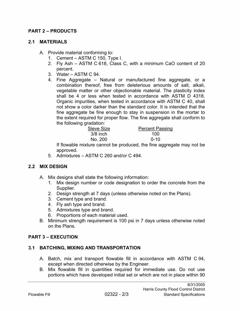
8/31/2005 Harris County Flood Control District Flowable Fill 02322 - 2/3 Standard Specifications
PART 2 – PRODUCTS 2.1 MATERIALS
A. Provide material conforming to: 1. Cement – ASTM C 150, Type I. 2. Fly Ash – ASTM C 618, Class C, with a minimum CaO content of 20
percent. 3. Water – ASTM C 94. 4. Fine Aggregate – Natural or manufactured fine aggregate, or a
combination thereof, free from deleterious amounts of salt, alkali, vegetable matter or other objectionable material. The plasticity index shall be 4 or less when tested in accordance with ASTM D 4318. Organic impurities, when tested in accordance with ASTM C 40, shall not show a color darker than the standard color. It is intended that the fine aggregate be fine enough to stay in suspension in the mortar to the extent required for proper flow. The fine aggregate shall conform to the following gradation:
Sieve Size Percent Passing 3/8 inch 100 No. 200 0-10
If flowable mixture cannot be produced, the fine aggregate may not be approved.
5. Admixtures – ASTM C 260 and/or C 494. 2.2 MIX DESIGN
A. Mix designs shall state the following information: 1. Mix design number or code designation to order the concrete from the
Supplier. 2. Design strength at 7 days (unless otherwise noted on the Plans). 3. Cement type and brand. 4. Fly ash type and brand. 5. Admixtures type and brand. 6. Proportions of each material used.
B. Minimum strength requirement is 100 psi in 7 days unless otherwise noted on the Plans.
PART 3 – EXECUTION 3.1 BATCHING, MIXING AND TRANSPORTATION
A. Batch, mix and transport flowable fill in accordance with ASTM C 94, except when directed otherwise by the Engineer.
B. Mix flowable fill in quantities required for immediate use. Do not use portions which have developed initial set or which are not in place within 90
8/31/2005 Harris County Flood Control District Standard Specifications 02322 - 3/3 Flowable Fill
minutes after the initial water has been added. C. Do not mix flowable fill while the air temperature is at or below 35 degrees
F. without prior approval of the Engineer. 3.2 PLACEMENT
A. Seal off the area to be repaired. B. Monitor and control the fluid pressure during placement of flowable fill prior
to set. Take appropriate measures to avoid excessive pressures that may damage or displace structures or cause flotation. Cease operations if flowable fill is observed leaking from the repair area. Repair or replace damaged or displaced structures at no cost to the District.
C. Do not place flowable fill under water without authorization from the Engineer.
3.3 TESTING AND INSPECTION
A. Refer to Section 01457 – Construction Tests and Inspection. 3.4 CLEAN UP
A. Clean up excess flowable fill discharged from the work area and remove excess flowable fill from pipes at no cost to the District.
B. Refer to Section 02120 – Material Disposal.
END OF SECTION

8/31/2005 Harris County Flood Control District Standard Specifications 02361 - 1/2 Silt Fences
SECTION 02361
SILT FENCES
PART 1 – GENERAL 1.1 SUMMARY
A. Section includes requirements for furnishing, installing, maintaining and removing temporary silt fences.
1.2 MEASUREMENT AND PAYMENT
A. Measurement and payment is as noted on the Unit Price Schedule. B. Refer to Section 01270 – Measurement and Payment for unit price
procedures. C. No separate measurement and payment will be made for maintenance or
removal of accumulated sediment. Removal of the silt fence is incidental to the cost of the silt fence.
1.3 REFERENCES
A. AASHTO M 288 – Geotextile Specification for Highway Applications. B. ASTM D 4355 – Deterioration of Geotextiles by Exposure to Light,
Moisture and Heat in a Xenon-Arc Type Apparatus. C. ASTM D 4491 – Water Permeability of Geotextiles by Permittivity. D. ASTM D 4632 – Grab Breaking Load and Elongation of Geotextiles. E. ASTM D 4751 – Determining Apparent Opening Size of a Geotextile.
1.4 SUBMITTALS
A. Refer to Section 01330 – Submittal Procedures. B. Submit catalog data and mill certificate for the silt fence geotextile and
catalog data for welded wire fabric mesh or plastic grid mesh reinforcement to be used.
PART 2 – PRODUCTS 2.1 GEOTEXTILE FABRIC
A. Geotextile fabric shall consist of long-chain synthetic polymers composed of at least 95 percent by weight of polyolefins in a woven fabric.
B. Geotextile fabric shall contain stabilizers and/or inhibitors to make the fibers resistant to deterioration resulting from exposure to sunlight or heat. The geotextile fabric shall be resistant to commonly encountered soil chemicals, mildew, rot and insects.

8/31/2005 Harris County Flood Control District Silt Fences 02361 - 2/2 Standard Specifications
C. Geotextile fabric shall be free of defects or flaws that affect its physical properties.
D. Provide a geotextile fabric with a minimum grab strength of 100 lbs (ASTM D 4632).
E. Provide silt fence with properties in accordance with AASHTO M 288 Geotextile Specification for Highway Applications Table 6.
2.2 SUPPORTS
A. Provide wooden stakes or steel fence supports having a minimum length of 4 feet.
B. For reinforced fence, provide mesh reinforcement of galvanized 2 inch by 4 inch welded wire fabric mesh or plastic grid mesh reinforcement (refer to Section 01562 – Construction Fence).
PART 3 – EXECUTION 3.1 GENERAL
A. Install silt fences at locations shown on Plans or as approved by the Engineer.
B. Place silt fences in a continuous manner and transverse to the runoff. Place the silt fence to follow the contours of the site. Do not allow water to flow around the end of the fence.
C. Provide continuous rolls of the silt fence fabric and cut to length to minimize the use of fabric joints. When joints are necessary, the fabric shall be spliced together only at a support with a minimum 6 inch overlap.
3.2 MAINTENANCE
A. Inspect silt fences after each rainfall, daily during periods of daily rainfall, and, at a minimum, once every week. Repair and/or replace any component of the silt fence that becomes defective from intended use.
B. Remove sediment deposits when the deposit reaches 1/3 the height of the fence. Dispose of sediment properly.
C. Remove silt fences and dispose of any sediment accumulations promptly when directed by Engineer.
3.3 DAMAGED MATERIAL
A. Repair damage to silt fences and supports immediately. 3.4 DISPOSAL
A. Refer to Section 02120 – Material Disposal.
END OF SECTION

8/31/2005 Harris County Flood Control District Standard Specifications 02364 - 1/3 Filter Dams
SECTION 02364
FILTER DAMS
PART 1 – GENERAL 1.1 SUMMARY
A. Section includes requirements for furnishing, installing, maintaining and removing filter dams.
1.2 MEASUREMENT AND PAYMENT
A. Measurement and payment is as noted on the Unit Price Schedule. B. Refer to Section 01270 – Measurement and Payment for unit price
procedures. C. Geotextile, excavation and disposal, granular fill and reinforcing wire will
not be measured separately. D. No separate payment shall be made for removal of accumulated sediment.
Maintenance and removal and subsequent reinstallation, if required, of the filter dam are incidental to the cost of the filter dam.
1.3 REFERENCES
A. ASTM A 975 – Double-Twisted Hexagonal Mesh Gabions and Revet Mattresses (Metallic-Coated Steel Wire or Metallic-Coated Steel Wire With Poly(Vinyl Chloride) (PVC) Coating).
1.4 SUBMITTALS
A. Refer to Section 01330 – Submittal Procedures. B. Submit catalog data and mill certificate for geotextile and catalog data for
wire to be used. C. Submit gradation for granular fill shown on the Plans.
PART 2 – PRODUCTS 2.1 GRANULAR FILL
A. Provide granular fill as noted on the Plans. B. Refer to Section 02378 – Riprap and Granular Fill.
2.2 WIRE COATING
A. Style 1 – zinc coated prior to being double twisted into mesh in accordance with ASTM A 975.

8/31/05 Harris County Flood Control District Filter Dams 02364 - 2/3 Standard Specifications
2.3 WIRE MESH FOR REINFORCEMENT
A. Provide 20 gauge galvanized double-twisted hexagonal wire mesh and tie wires or as shown on the Plans.
2.4 CONNECTION WIRES AND STIFFENERS
A. Provide spiral binders, lacing wire and stiffeners made of wire having the same coating material and same wire size as the wire mesh for reinforcement.
2.5 GEOTEXTILE SEPARATION FABRIC
A. Provide a geotextile of woven or spunbond nonwoven fibers consisting of long-chain synthetic polymers composed of at least 95 percent by weight of polyolefins. Provide geotextile fabric equal to the following average roll values or as directed by the Engineer: 1. Minimum average roll value.
a. Elongation < 50 percent. b. Grab Strength ≥ 200 pounds. c. Puncture Strength ≥ 75 pounds. d. UV Stability (retained strength) ≥ 50 percent after 500 hours of
exposure. 2. Maximum average roll value.
a. Apparent Opening Size (AOS) – 0.212 to 0.6 mm (#70 to #30 US sieve).
B. Refer to Section 02379 – Geotextiles for Erosion Control Systems for storage and handling precautions and requirements.
PART 3 – EXECUTION 3.1 INSTALLATION
A. Install in accordance with the Plans. 3.2 MAINTENANCE
A. Sediment Accumulation. 1. Remove accumulated sediment as needed or when directed by the
Engineer. 2. Reshape the filter dam as needed or when directed by the Engineer.
3.3 REMOVAL
A. Maintain the filter dam, in place, throughout the duration of the Project. Remove when directed by the Engineer. Sod the exposed earth beneath the filter dam and areas damaged by the removal process in accordance with Section 02921 – Turf Establishment.

8/31/2005 Harris County Flood Control District Standard Specifications 02364 - 3/3 Filter Dams
3.4 SEDIMENT DISPOSAL
A. Refer to Section 02120 – Material Disposal.
END OF SECTION

8/31/2003 Harris County Flood Control District Stabilized Standard Specifications 02365 - 1/2 Construction Access
SECTION 02365
STABILIZED CONSTRUCTION ACCESS
PART 1 – GENERAL 1.1 SUMMARY
A. Section includes requirements for construction, maintenance and removal of stabilized construction access.
1.2 MEASUREMENT AND PAYMENT
A. Measurement and payment is as noted on the Unit Price Schedule. B. Refer to Section 01270 – Measurement and Payment for unit price
procedures. C. No separate measurement and payment will be made for maintenance or
removal. 1.3 SUBMITTALS
A. Refer to Section 01330 – Submittals. B. Refer to Section 02379 – Geotextiles for Erosion Control Systems. C. Submit gradation for granular fill.
PART 2 – PRODUCTS 2.1 GEOTEXTILE SEPARATION FABRIC
A. Provide a geotextile of woven or spunbond nonwoven fibers consisting of long-chain synthetic polymers composed of at least 95 percent by weight of polyolefins. Provide geotextile fabric equal to the following average roll values or as directed by the Engineer: 1. Minimum average roll value.
a. Elongation < 50 percent. b. Grab Strength ≥ 200 pounds. c. Puncture Strength ≥ 75 pounds. d. UV Stability (retained strength) ≥ 50 percent after 500 hours of
exposure. 2. Maximum average roll value.
a. Apparent Opening Size (AOS) – 0.212 to 0.6 mm (#70 to #30 US sieve).

8/31/2003 Stabilized Harris County Flood Control District Construction Access 02365 - 2/2 Standard Specifications
2.2 GRANULAR FILL
A. Refer to Section 02378 – Riprap and Granular Fill. PART 3 – EXECUTION 3.1 GENERAL
A. Provide stabilized access, washing areas and parking areas at locations shown on the Plans or as approved by the Engineer.
B. Furnish and place geotextile fabric as a permeable separator to prevent mixing of granular fill with underlying soil.
C. Place 3 inch to 5 inch granular fill to dimensions and depths shown on the Plans or as directed by the Engineer. The minimum thickness shall be 8 inches.
D. Roads and parking areas shall be graded to provide sufficient drainage away from stabilized areas. Use sandbags, gravel, boards or similar methods to prevent sediment from entering public rights-of-way, storm drains, ditches and watercourses.
3.2 MAINTENANCE
A. Inspect and maintain stabilized areas daily. Provide periodic top dressing with additional granular fill as necessary.
B. Repair or replace components of stabilized access areas that become defective from intended use.
C. Maintain stabilized access areas until acceptance of the Project or as directed by Engineer.
D. Remove stabilized access promptly when directed by Engineer. Restore areas where stabilized construction access was removed to final project grade in preparation of turf establishment by others.
3.3 DISPOSAL
A. Refer to Section 02120 – Material Disposal.
END OF SECTION
8/31/2005 Harris County Flood Control District Standard Specifications 02374 - 1/4 Articulating Concrete Block
SECTION 02374
ARTICULATING CONCRETE BLOCK
PART 1 – GENERAL 1.1 SUMMARY
A. Section includes requirements for furnishing and installing articulating concrete blocks. This Section does not include cabled block installations.
1.2 MEASUREMENT AND PAYMENT
A. Measurement and payment is as noted on the Unit Price Schedule. B. Refer to Section 01270 – Measurement and Payment for unit price
procedures. C. Turn downs and grout will not be measured separately but are incidental to
surface measurement. D. Concrete placed around outfall pipes will be paid separately as Concrete
Channel Lining. 1.3 REFERENCES
A. ASTM C 33 – Concrete Aggregates. B. ASTM C 140 – Sampling and Testing Concrete Masonry Units and
Related Units. C. ASTM C 150 – Portland Cement. D. ASTM C 476 – Grout for Masonry. E. ASTM D 698 – Laboratory Compaction Characteristics of Soil Using
Standard Effort (12,400 ft-lbf/ft3 (600 kN-m/m3)). F. ASTM D 6684 – Materials and Manufacture of Articulating Concrete Block
(ACB) Revetment Systems. G. “Design Manual for Articulating Concrete Block Systems,” Paul E. Clopper,
Harris County Flood Control District, May 2001. 1.4 SUBMITTALS
A. Refer to Section 01330 – Submittal Procedures. B. Submit the following items for approval by the Engineer:
1. Product Information Sheet(s) containing product description, statement of intended/designed use of product, product photographs and manufacturer’s recommended installation procedure.
2. Articulating concrete block hydraulic stability laboratory test results conducted per FHWA RD-89-199.
3. Grout mix design.

8/31/2005 Harris County Flood Control District Articulating Concrete Block 02374 - 2/4 Standard Specifications
4. Certificate of Product Compliance signed by an authorized official of the supplier for articulating concrete blocks. The Certificate shall attest that the articulating concrete blocks satisfy the requirements in this Section.
C. For approval of an alternate articulating concrete block product submit the following, in addition to the above requirements: 1. Hydraulic stability (factor of safety) calculations for both shear stress
and velocity for both level and projecting block conditions using the method presented in the HCFCD “Design Manual for Articulating Concrete Block Systems” provided and sealed by a licensed Texas Professional Engineer.
1.5 DELIVERY, STORAGE AND HANDLING OF MATERIALS
A. Inspect blocks delivered to the site for damage. Unload and store with a minimum of handling. Protect the concrete blocks from damage. Do not store concrete blocks directly on the ground and keep them free of dirt and debris. Dispose of damaged blocks.
B. Handle materials to ensure delivery to the site in a sound, undamaged condition. Protect geotextile in accordance with the applicable portions of Section 02379 – Geotextiles for Erosion Control Systems.
C. Blocks cracked, gouged, chipped, dented, honeycombed, missing tabs or more than ¼ of the block or otherwise damaged will be considered nonconforming.
PART 2 – PRODUCTS 2.1 MATERIALS
A. Block. 1. Provide drycast positive interlocking open-cell articulating concrete
block for hand placement. 2. The physical requirements for the concrete in the concrete blocks are:
a minimum 4,000 psi compressive strength at 28 days, a maximum water absorption of 7 percent and a minimum specific weight of 130 lbs/ft3 (ASTM C 140). Cement shall be Portland cement (ASTM C 150).
3. Provide articulating concrete block meeting the hydraulic stability requirements shown on the Plans.
4. Provide concrete blocks cast of approved aggregate with no slump concrete and machine-made by vibration and compression.
5. Provide aggregate meeting the requirements of ASTM C 33 except grading.
6. The open area of the assembled blocks shall range from 18-23 percent open area, which may include penetrations within the concrete blocks and the non-grouted spacing between blocks.

8/31/2005 Harris County Flood Control District Standard Specifications 02374 - 3/4 Articulating Concrete Block
B. Structural grout. 1. Provide grout mixture that is coarse and proportioned in accordance
with ASTM C 476. 2.2 FILTER MEDIA
A. Provide filter media as shown on the Plans. PART 3 – EXECUTION 3.1 FOUNDATION PREPARATION
A. Construct areas on which the geotextile and concrete block are to be placed in accordance with Section 02315 – Excavating and Backfilling.
B. Excavate and prepare termination trenches in accordance with lines, grades and dimensions shown on the Plans.
3.2 INSTALLATION OF GEOTEXTILE FILTER FABRIC
A. Underlay all concrete block with a geotextile in accordance with Section 02379 – Geotextiles for Erosion Control Systems.
3.3 INSTALLATION OF CONCRETE BLOCKS
A. Install concrete blocks in accordance with manufacturer’s recommendations. When requested by the Engineer, the manufacturer’s qualified representative shall be present during the first week of placement to assist the Contractor and provide on-call assistance at no cost to the District.
B. No blocks shall project more than 1/2 inch vertically beyond adjacent blocks.
C. Prevent damage to the soil surface after foundation preparation and prior to block placement. Repair damage to the slope surface before continuing at no cost to the District.
D. Place individual blocks to interlock side-to-side and/or end-to-end in accordance with manufacturer’s recommendations.
E. As the installation progresses, backfill the perimeter termination trenches and compact the fill. Use the fill material shown on the Plans or as directed by the Engineer.
F. Inspect the concrete block system for damage prior to filling. Dispose of and replace damaged blocks.
G. Fill the voids of the concrete block revetment to 1 inch above the block with topsoil in accordance with Section 02911 – Topsoil.
H. No more than 7 days shall pass between placement of the geotextile and the topsoil filling of the concrete block voids to prevent damage from ultraviolet radiation to the geotextile.

8/31/2005 Harris County Flood Control District Articulating Concrete Block 02374 - 4/4 Standard Specifications
3.4 MATERIAL DISPOSAL
A. Refer to Section 02120 – Material Disposal.
END OF SECTION

8/31/2005 Harris County Flood Control District Concrete Channel Lining And Standard Specifications 02376 - 1/1 Concrete Interceptor Structures
SECTION 02376
CONCRETE CHANNEL LINING AND CONCRETE INTERCEPTOR STRUCTURES
PART 1 – GENERAL 1.1 SUMMARY
A. Section includes requirements for constructing concrete channel lining and
concrete interceptor structures. 1.2 MEASUREMENT AND PAYMENT
A. Measurement and payment is as noted on the Unit Price Schedule. B. Refer to Section 01270 – Measurement and Payment for unit price
procedures. C. Toewalls, seal slab, grade beams, joint materials, weep holes, saw cutting
and appurtenances will not be measured separately, but are incidental to surface measurement.
1.3 SUBMITTALS
A. Refer to Section 01330 – Submittals. B. Refer to Section 03310 – Concrete.
PART 2 – PRODUCTS 2.1 CONCRETE
A. Refer to Section 03310 – Concrete. B. Provide structural concrete for concrete channel lining and interceptor
structures. Refer to Section 03310 – Concrete. C. Provide non-structural concrete for the seal slab. Refer to Section 03310 –
Concrete. PART 3 – EXECUTION 3.1 EXCAVATION AND FILL
A. Excavate the Channel: Refer to Section 02316 – Structural Excavating and
Backfilling. B. Refer to Section 03310 – Concrete.
END OF SECTION

8/31/2005 Harris County Flood Control District Standard Specifications 02377 - 1/1 Rectangular Concrete Channel
SECTION 02377
RECTANGULAR CONCRETE CHANNEL
PART 1 – GENERAL 1.1 SUMMARY
A. Section includes requirements for constructing rectangular concrete channels.
1.2 MEASUREMENT AND PAYMENT
A. Measurement and payment is as noted on the Unit Price Schedule. B. Refer to Section 01270 – Measurement and Payment for unit price
procedures. C. Toewalls, seal slab, grade beams, joint materials, weep holes and
appurtenances will not be measured separately, but are incidental to surface measurement.
PART 2 – PRODUCT 2.1 CONCRETE
A. Refer to Section 03310 – Concrete. PART 3 – EXECUTION 3.1 INSTALLATION
A. Refer to Section 02316 – Structural Excavating and Backfilling. B. Refer to Section 03310 – Concrete. C. For concrete designed without retarding agents and placed in ambient
temperatures above 50 degrees F., leave rectangular concrete channel wall forms in a minimum of 24 hours after the concrete is placed.
D. For concrete designed with retarding agents and/or placed in ambient temperatures below 50 degrees F., remove forms when approved by the Engineer.
E. Tolerances: 1. Screed the concrete surface to be true within 1/4 inch in 10 feet. 2. Plumb walls to within 1/8 inch from top to bottom.
END OF SECTION

8/31/2005 Harris County Flood Control District Standard Specifications 02378 - 1/4 Riprap and Granular Fill
SECTION 02378
RIPRAP AND GRANULAR FILL
PART 1 – GENERAL 1.1 SUMMARY
A. Section includes requirements for furnishing and installing riprap and granular fill and filling and burying riprap, when required.
1.2 MEASUREMENT AND PAYMENT
A. Where there is not a separate item listed on the Unit Price Schedule for work in this Section, no separate measurement and payment is made. Include cost for work under this Section in the related item listed on the Unit Price Schedule.
B. Measurement and payment is as noted on the Unit Price Schedule. C. Refer to Section 01270 – Measurement and Payment for unit price
procedures. D. Excavation for riprap and buried riprap will not be measured separately, but
is incidental to riprap surface measurement. E. Riprap and granular fill used in toe walls, grade beams or termination
trenches are incidental to surface measurement. F. On-site topsoil will not be measured and paid separately, but is incidental
to riprap surface measurement. G. Imported topsoil will be paid for as noted on the Unit Price Schedule.
1.3 DELIVERY, STORAGE AND HANDLING
A. Keep the storage area clean, firm, smooth and well drained in order that the product can be placed with a minimum of foreign matter.
B. Stockpile and handle riprap and granular fill to minimize segregation of particle sizes either in the stockpile or while loading, hauling and handling.
PART 2 – PRODUCTS 2.1 RIPRAP
A. Provide riprap consisting of broken concrete or stone. Provide riprap that is dense, durable and hard material free from cracks, seams and other defects which would increase deterioration from handling and natural causes.
B. Shape and Dimensions. 1. Provide riprap in cubic form, rather than elongated (flat) shapes. 2. Provide riprap with a minimum thickness of 6 inches.
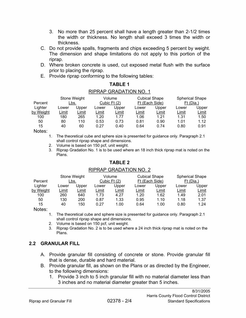
8/31/2005 Harris County Flood Control District Riprap and Granular Fill 02378 - 2/4 Standard Specifications
3. No more than 25 percent shall have a length greater than 2-1/2 times the width or thickness. No length shall exceed 3 times the width or thickness.
C. Do not provide spalls, fragments and chips exceeding 5 percent by weight. The dimension and shape limitations do not apply to this portion of the riprap.
D. Where broken concrete is used, cut exposed metal flush with the surface prior to placing the riprap.
E. Provide riprap conforming to the following tables:
TABLE 1 RIPRAP GRADATION NO. 1
Stone Weight Volume Cubical Shape Spherical Shape Percent Lbs. Cubic Ft (2) Ft (Each Side) Ft (Dia.) Lighter Lower Upper Lower Upper Lower Upper Lower Upper
by Weight Limit Limit Limit Limit Limit Limit Limit Limit 100 180 265 1.20 1.77 1.06 1.21 1.31 1.50 50 80 110 0.53 0.73 0.81 0.90 1.01 1.12 15 40 60 0.27 0.40 0.64 0.74 0.80 0.91
Notes: 1. The theoretical cube and sphere size is presented for guidance only. Paragraph 2.1
shall control riprap shape and dimensions. 2. Volume is based on 150 pcf, unit weight. 3. Riprap Gradation No. 1 is to be used where an 18 inch thick riprap mat is noted on the
Plans.
TABLE 2 RIPRAP GRADATION NO. 2
Stone Weight Volume Cubical Shape Spherical Shape Percent Lbs. Cubic Ft (2) Ft (Each Side) Ft (Dia.) Lighter Lower Upper Lower Upper Lower Upper Lower Upper
by Weight Limit Limit Limit Limit Limit Limit Limit Limit 100 260 640 1.73 4.27 1.20 1.62 1.49 2.01 50 130 200 0.87 1.33 0.95 1.10 1.18 1.37 15 40 150 0.27 1.00 0.64 1.00 0.80 1.24
Notes: 1. The theoretical cube and sphere size is presented for guidance only. Paragraph 2.1
shall control riprap shape and dimensions. 2. Volume is based on 150 pcf, unit weight. 3. Riprap Gradation No. 2 is to be used where a 24 inch thick riprap mat is noted on the
Plans. 2.2 GRANULAR FILL
A. Provide granular fill consisting of concrete or stone. Provide granular fill that is dense, durable and hard material.
B. Provide granular fill, as shown on the Plans or as directed by the Engineer, to the following dimensions: 1. Provide 3 inch to 5 inch granular fill with no material diameter less than
3 inches and no material diameter greater than 5 inches.

8/31/2005 Harris County Flood Control District Standard Specifications 02378 - 3/4 Riprap and Granular Fill
2. Provide 4 inch to 8 inch granular fill with no material diameter less than 4 inches and no material diameter greater than 8 inches.
3. Provide riprap Gradation No. 1 and Gradation No. 2 as shown on the Plans or as directed by the Engineer.
C. Do not provide spalls, fragments and chips exceeding 5 percent by weight. D. Where broken concrete is used, cut exposed metal flush with the surface
prior to placing granular fill. 2.3 GEOTEXTILE
A. Refer to Section 02379 – Geotextiles for Erosion Control Systems. PART 3 – EXECUTION 3.1 GRADE PREPARATION
A. Refer to Section 02241 – Care and Control of Water. B. Trim and dress the channel bottom and side slopes to proper lines and
grade prior to placing riprap or granular fill. Where shown on the Plans, place geotextile in accordance with Section 02379 – Geotextiles for Erosion Control Systems.
C. The Engineer will inspect prepared section prior to placing geotextile, riprap or granular fill.
3.2 EXCAVATION AND FILL
A. Excavate the channel. Refer to Section 02315 – Excavating and Backfilling.
B. Excavate for riprap. Refer to Section 02316 – Structural Excavating and Backfilling.
3.3 RIPRAP OR GRANULAR FILL PLACEMENT
A. Place the riprap or granular fill to the slopes, lines and grades as shown on the Plans.
B. To establish a well-graded mass of riprap with minimal voids, fill voids between larger riprap blocks with spalls and smaller blocks of the largest feasible size to form a compact mass. Do not place spalls and small blocks in place of larger size riprap or granular fill.
C. Install riprap and granular fill mat to the thickness as shown on the Plans. Riprap shall have minimum mat thickness as shown on the gradation tables.
D. Place the riprap and granular fill to avoid displacement or damage to the prepared surface or geotextile and in a manner to avoid segregation of particle sizes.

8/31/2005 Harris County Flood Control District Riprap and Granular Fill 02378 - 4/4 Standard Specifications
E. Fill riprap voids and bury riprap a minimum of 6 inches with topsoil on side slopes as directed by the Engineer.
END OF SECTION

8/31/2005 Harris County Flood Control District Geotextiles for Standard Specifications 02379 - 1/3 Erosion Control Systems
SECTION 02379
GEOTEXTILES FOR EROSION CONTROL SYSTEMS
PART 1 – GENERAL 1.1 SUMMARY
A. Section includes the requirements for furnishing and installing geotextiles used for filter applications beneath erosion control systems.
1.2 MEASUREMENT AND PAYMENT
A. Where there is not a separate item listed on the Unit Price Schedule for work in this Section, no separate measurement and payment is made. Include cost for work under this Section in the related item listed on the Unit Price Schedule.
B. Measurement and payment is as noted on the Unit Price Schedule. C. Refer to Section 01270 – Measurement and Payment for unit price
procedures. D. Staples and termination trenches are incidental to the geotextile installation
and will not be paid for separately. E. Geotextile used in termination trenches and overlaps is incidental to surface
measurement. 1.3 REFERENCES
A. AASHTO M 288 – Geotextile Specification for Highway Applications. B. ASTM D 4354 – Sampling of Geosynthetics for Testing. C. ASTM D 4355 – Deterioration of Geotextiles by Exposure to Light,
Moisture and Heat in a Xenon-Arc Type Apparatus. D. ASTM D 4491 – Water Permeability of Geotextiles by Permittivity. E. ASTM D 4533 – Trapezoid Tearing Strength of Geotextiles. F. ASTM D 4632 – Grab Breaking Load and Elongation of Geotextiles. G. ASTM D 4751 – Determining Apparent Opening Size of a Geotextile. H. ASTM D 4833 – Index Puncture Resistance of Geotextiles,
Geomembranes, and Related Products. 1.4 SUBMITTALS
A. Refer to Section 01330 – Submittal Procedures. B. Submit catalog data. Clearly indicate the material(s) to be used. Provide
geotextiles in accordance with the range of average roll values designated on the Plans. Attach a 4 inch by 4 inch sample to the submittal for each geotextile to be installed.

8/31/2005 Geotextiles for Harris County Flood Control District Erosion Control Systems 02379 - 2/3 Standard Specifications
C. Submit manufacturer’s recommended installation method for geotextile installation based on its designated use.
1.5 PRODUCT DELIVERY, STORAGE AND HANDLING
A. Inspect geotextile filter fabric delivered to the site for damage. Protect the geotextile from construction traffic damage.
B. Store the geotextile in accordance with the manufacturer’s recommendations for outdoor storage.
C. Protect the geotextile from direct sunlight and ultraviolet radiation. Keep the fabric wrapped in its protective covering during shipping and storage. The label affixed to each roll should state manufacturer’s name, geotextile name (product designation) and type, lot number, roll number and roll dimensions including length, width and gross weight. Replace or repair damaged geotextile or protective covering as directed by the Engineer.
D. Do not use hooks or other sharp objects to handle the geotextile. Do not drag the geotextile on the ground.
PART 2 – PRODUCTS 2.1 MATERIALS
A. Provide geotextile of woven monofilament material, as noted on the Plans or Unit Price Schedule. Woven slit film geotextiles or nonwoven geotextiles are not acceptable.
B. Provide geotextile fibers consisting of long chain synthetic polymers, composed of at least 95 percent by weight polyesters or polyolefins. These fibers shall be formed into a stable network such that the filaments or yarns retain their dimensional stability relative to each other, including the edges. Material shall be resistant to deterioration from ultraviolet radiation, heat exposure and commonly encountered soil chemicals, mildew, rot and insects.
C. Provide geotextile in accordance with requirements shown on the Plans. PART 3 – EXECUTION 3.1 GRADE PREPARATION
A. Refer to Section 02241 – Care and Control of Water. B. Construct areas on which the geotextiles for erosion control systems are to
be placed to the lines and grades shown on the Plans. Prepare subgrade in accordance with Section 02315 – Excavating and Backfilling. Prior to placement of any geotextile for erosion control systems, Engineer will inspect the prepared subgrade.
C. Excavate and prepare termination trenches in accordance with the manufacturer’s recommendations or as shown on the Plans.
8/31/2005 Harris County Flood Control District Geotextiles for Standard Specifications 02379 - 3/3 Erosion Control Systems
D. Immediately prior to placing the geotextile, the Engineer shall inspect and approve the prepared section.
3.2 GEOTEXTILE INSTALLATION
A. Do not leave the geotextile exposed to the sun longer than the manufacturer recommends to minimize damage due to ultraviolet radiation. Do not install a geotextile if it has been removed from its protective covering longer than the manufacturer recommends.
B. For placement of geotextile, follow manufacturer’s installation instructions and at a minimum: 1. Place the geotextile directly on the prepared area. Lay the geotextile
smoothly on the subgrade to minimize tension, stress, folds and wrinkles.
2. After placement, do not unnecessarily walk on or disturb the geotextile unless required to preserve contact with the subgrade. Equipment is not allowed on the unprotected geotextile. Protect the geotextile from clogging, penetrations, tears and other damage during installation.
3. Place the geotextile strips from downstream to upstream. Overlap successive geotextile sheets such that the upstream sheet is placed over the downstream sheet and/or the upslope over the downslope.
4. Overlap adjoining geotextile sections a minimum of 2 feet. 5. Replace or repair any geotextile damaged during the placement of
riprap or other materials at no additional cost to the District. Place a geotextile patch of the same material over the area and extend a minimum of 3 feet beyond the perimeter of the tear and/or damage. Orient the patch material so that its fibers are aligned with the damaged geotextile fibers.
C. Placements under water are not permitted without Engineer’s approval.
END OF SECTION
8/31/2005 Harris County Flood Control District Standard Specifications 02462 - 1/7 Steel Sheet Piling
SECTION 02462
STEEL SHEET PILING
PART 1 – GENERAL 1.1 SUMMARY
A. Section includes requirements for installing steel sheet piling and accessories, such as walers, tie rods, anchor walls and tie backs.
1.2 MEASUREMENT AND PAYMENT
A. Measurement and payment is as noted on the Unit Price Schedule. B. Refer to Section 01270 – Measurement and Payment for unit price
procedures. C. Where anchored wall systems are used, separate bid items will be listed
for the retaining wall and the anchor wall. 1. Include costs of the tie rods and accessories in the bid price for the
anchor wall. 2. Include costs of walers in the bid price for the associated wall.
D. Measurement and payment is based on the horizontal linear foot piling after installation.
1.3 REFERENCES
A. AISC – Specifications for the Design, Fabrication and Erection of Structural Steel for Buildings.
B. AISC – Code of Standard Practice for Steel Buildings and Bridges.
C. ASTM A 36 – Carbon Structural Steel. D. ASTM A 307 – Carbon Steel Bolts and Studs, 60 000 PSI Tensile
Strength. E. ASTM A 325 – Structural Bolts, Steel, Heat Treated 120-105 ksi Minimum
Tensile Strength. F. ASTM A 328 – Steel Sheet Piling. G. ASTM A 572 – High-Strength Low-Allow Columbium-Vanadium Structural
Steel. H. ASTM A 588 – High-Strength Low-Alloy Structural Steel with 50 ksi
[345 Mpa] Minimum Yield Point to 4 in. [100 mm] Thick. I. ASTM A 615 – Deformed and Plain Billet-Steel Bars for Concrete
Reinforcement. J. ASTM A 668 – Steel Forgings, Carbon and Alloy, for General Industrial
Use. K. ASTM A 690 – High-Strength Low Allow Steel H-Piles and Sheet Piling
for Use in Marine Environments.
8/31/2005 Harris County Flood Control District Steel Sheet Piling 02462 - 2/7 Standard Specifications
L. AWS D1.1 – Structural Welding Code – Steel. 1.4 SUBMITTALS
A. Refer to Section 01330 – Submittal Procedures. B. Submit Shop Drawings:
1. Shop Drawings shall show the layout pattern, type of piling, details of special fabricated shapes, and accessories, and other pertinent details and information. Show the location, type, and size of welds and fastenings and welding process. Indicate type of material for each item. Show special fittings and method of manufacturing (prefabricated or built up). Show splice locations and supplemental reinforcement at splices.
2. Shop Drawings shall show walers, tie rods, anchor walls and accessories, where these items are part of the retaining wall system.
C. Product information is required. Submit catalog data (cut sheets) on material. On tables, clearly indicate material to be used. Include structural properties, dimensions, laying length, details of the sheet pile and the interlock joint and correct interlocking methods.
D. Where the strength of the interlock joint is specified, submit certified test reports indicating that the specified minimum interlock joint strength has been met.
E. A certified statement from the protective coating applicator that the sheet piling, walers, tie rods and other miscellaneous steel hardware items have been coated as specified.
F. Nondestructive examinations: Submit test reports required by this Section including, but not limited to, the AWS Standard listed.
1.5 DELIVERY, STORAGE AND HANDLING
A. Store sheet piles and accessories in an area free of standing water and elevated off the ground.
B. Keep pile interlocks clean and free of sand, gravel, mud and other potential obstructions.
C. Prevent damage to sheet piling, protective coating and accessories during handling.
1.6 PROTECTION OF ADJACENT FACILITIES
A. Existing Facilities. 1. Before the start of construction, adequately protect any existing
structures from damage. Repair damage to permanent facilities due to negligence or lack of adequate protection at no cost to the District. Prior to beginning of the project, a joint inspection will be made by the Contractor and Engineer to determine the condition of the existing structures.

8/31/2005 Harris County Flood Control District Standard Specifications 02462 - 3/7 Steel Sheet Piling
B. New Concrete Work. 1. Schedule concrete placement operations so that pile driving will be
complete before any concrete is placed within 50 feet of sheet piling. 1.7 COORDINATION
A. Notify the Engineer at least 48 hours prior to beginning pile driving operations.
PART 2 – PRODUCTS 2.1 STEEL SHEET PILES
A. Provide hot rolled steel sheet piling which meets the requirements of ASTM A 328, ASTM A 572 or ASTM A 690. ASTM A 690 sheet piling, or piling with protective coating, is required in marine environments or as shown on the Plans.
B. Structural property requirements are shown on the Plans. Select the grade of steel and sheet pile section that meets or exceeds these requirements.
C. Provide steel sheet piles and special fabricated shapes having a continuous jaw interlock joint throughout the entire length of the sheet.
D. Provide handling holes located in the sheet pile web. E. Provide sheet piles and interlocks free of excessive kinks, camber or twist
that would interfere with reasonably free sliding in the joint. F. Provide square and blunt shaped pile ends. G. Provide new sheet piles. Used sheet piling will not be accepted. H. Provide steel sheet piling products from a single manufacturer.
2.2 ACCESSORIES
A. Provide walers, beams, struts, angles and other miscellaneous metal accessories in accordance with ASTM A 36, unless noted otherwise on the Plans.
B. Provide bolts in accordance with ASTM A 325. 2.3 FABRICATION
A. Fabricate items such as wale beams, struts, closure sections and special sections in accordance with the requirements of the AISC Specifications for the Design, Fabrication and Erection of Structural Steel for Buildings.
B. Perform welding in accordance with the requirements of AWS D1.1 Structural Welding Code – Steel.

8/31/2005 Harris County Flood Control District Steel Sheet Piling 02462 - 4/7 Standard Specifications
2.4 FABRICATED CONNECTIONS
A. Provide connections for junction points and special angles. The connections shall be prefabricated by the sheet pile manufacturer or shop fabricated from split sheets. Cutting and welding to produce special fabricated connections in the field will be considered nonconforming.
B. Match fabricated connections for ASTM A 328 and ASTM A 572 sheet piles with material used in the sheet pile.
C. ASTM A 690 sheet pile connections shall be furnished with angles or plates made from ASTM A 588 steel and with ASTM A 325 Type 3 bolts.
D. Provide fabricated connections having handling holes located 4 inches to 6 inches from the top.
2.5 TIE RODS
A. Where tie rods are required for an anchored wall system, use either ASTM A 36 or ASTM A 615 tie rods, as noted on the Plans. The ASTM A 615 tie rods shall be equal to the grade 60 Dywidag Threadbar Reinforcing System.
2.6 PROTECTIVE COATING
A. Provide steel sheet piles, components and accessories having protective coating as noted on the Plans.
B. Notify the Engineer at least 48 hours prior to applying the protective coating. The coating applicator shall allow the Engineer access to these facilities to observe the protective coating preparation and application.
PART 3 – EXECUTION 3.1 INSTALLING STEEL SHEET PILES
A. Install sheet piling in strict accordance with the manufacturer’s recommendations. Select means, methods, equipment and procedures for installing the piles, and for templates and bracing required to install the piles within the tolerances specified.
B. Location and Tolerances. 1. Drive sheet piling at locations and to the lines, grades and depths as
shown on the Plans. 2. Vertical Tolerances.
a. In general, drive sheet pile to within 3 inches of the elevations shown on the Plans, except as noted below for hydraulic structures. Trim sheet piles tops as follows: 1) Where the sheet pile tops will be embedded in a concrete cap,
trimming sheet piling is not required. Embed handling holes completely in the concrete cap.

8/31/2005 Harris County Flood Control District Standard Specifications 02462 - 5/7 Steel Sheet Piling
2) Where a steel cap will be placed on the top of the wall, trim sheet piling as necessary to have level bearing of the cap on the sheet pile.
3) Where the sheet pile tops will be exposed, trim the tops of piling as necessary to the same level to provide a uniform appearance.
4) Where the sheet pile wall functions in a hydraulic structure, such as a drop structure or weir structure, all sheet pile tops shall be accurately driven to or cut off at the design elevation.
b. Variation from vertical (plumb) shall not exceed 1 inch in 10 feet. 3. Horizontal Tolerances.
a. Walls shall be straight and uniform in appearance. Maintain a tolerance of 2 inches from the Plan layout. In sheet pile lined channels, the face to face distance between the walls shown on the Plans shall be maintained, as a minimum.
C. Setting Sheet Piling. 1. If necessary to comply with the above tolerances, use a guide frame or
template to start piling. 2. Set and drive ball and socket joint piling with the ball end leading.
When the socket joint must lead, place a bolt or similar object in the bottom end to minimize socket clogging.
3. Guide each sheet pile into the interlocking joint of the previously placed pile.
4. Gradually lower pile after being threaded. Do not drop the pile into place.
5. Interlock piles in accordance with the manufacturer’s printed literature. Incorrect interlocking to make angles or bends will not be acceptable.
D. Pile Driving. 1. Drive piles vertically and in correct alignment so that the tops of the
piles lie on a straight line and to insure a proper interlocking of joints throughout the pile length.
2. Drive piles with a hammer of a size and weight appropriate for the pile and conditions encountered. A drop hammer will not be allowed. However, a hairpin stabbing hammer will be permitted to start the sheet pile, provided the piling is protected from damage.
3. Drive piles to required full Plan penetration using only the hammer. 4. Drive the piles in an acceptable manner to prevent the pile bottom from
drifting, becoming misaligned or loosing interlocking of sheets. Remove and replace any pile ruptured at the interlock or damaged in any other way at no additional cost to the District.
5. Water jetting is not permitted. 6. Do not overdrive piles, lift driven piles or jack driven piles.
3.2 FIELD CUTTING AND CONNECTING
A. Comply with the AISC Specification for the Design, Fabrication and

8/31/2005 Harris County Flood Control District Steel Sheet Piling 02462 - 6/7 Standard Specifications
Erection of Structural Steel for Buildings in the fabrication and erection of such items as wale beams, tie rods and special sections.
B. Drill bolt holes in order to obtain smooth, uniform holes of the proper diameter. Making bolt holes with a cutting torch is not permitted.
C. Splices. 1. Avoid splices of sheet piles and obtain approval of the Engineer prior
to using. a. Where allowed, the number of splices per pile shall be limited to 2
splices. 2. The piling to be spliced shall be ordered full length from the mill.
Match-mark and cut the pile at splice locations. As pile driving proceeds, splice the match-marked pieces to reconstruct the original sheet pile shipped from the mill. Splicing randomly selected sections is not permitted.
3. Provide splice plates on the flanges to compensate for not welding the interlocks where full section modulus is required in the region of the splice.
4. Stagger splices on adjacent piles by at least 2 feet. D. Cut off and replace, using full strength welds, the damaged portion of the
top of the piling if it is appreciably damaged during driving or by other means.
E. Perform welding in accordance with the requirements of AWS D1.1 Structural Welding Code – Steel.
3.3 EXCAVATION AND FILL
A. Operate machinery and equipment carefully around sheet piles to prevent damage to the piles.
B. Where required, refer to Section 02316 – Structural Excavating and Backfilling.
3.4 WEEP HOLES
A. Place weep holes, where shown on the Plans, in the web of the sheet pile, not in the flange.
3.5 SEALING HOLES
A. Seal holes, including the handling holes and holes for structural items such as bolts and tie rods as noted on the Plans.
B. Provide weep holes with a filtration system of graded gravel and geotextile, as shown on the Plans.

8/31/2005 Harris County Flood Control District Standard Specifications 02462 - 7/7 Steel Sheet Piling
3.6 TIE RODS
A. Tighten anchor rod nuts to remove all slack in the system before backfilling and installing the retaining wall cap.
3.7 PROTECTIVE COATING
A. Repair protective coating that is damaged during handling or installation in accordance with the coating manufacturer’s recommendations before backfilling.
END OF SECTION
8/31/2005 Harris County Flood Control District Standard Specifications 02464 - 1/2 Timber Bents
SECTION 02464
TIMBER BENTS
PART 1 – GENERAL 1.1 SUMMARY
A. Section includes requirements for installing timber bents on outfall pipes. 1.2 MEASUREMENT AND PAYMENT
A. Measurement and payment is as noted on the Unit Price Schedule. B. Refer to Section 01270 – Measurement and Payment for unit price
procedures. 1.3 REFERENCES
A. ASTM A 153 – Zinc Coating (Hot-Dip) on Iron and Steel Hardware. B. ASTM A 307 – Carbon Steel Bolts and Studs, 60 000 PSI Tensile
Strength. C. AWPA C2 – Lumber, Timbers, Bridge Ties and Mine Ties –
Preservative Treatment by Pressure Processes. D. AWPA C4 – Poles – Preservative Treatment by Pressure
Processes. E. AWPA P1/P13 – Standard for Coal Tar Creosote for Land, Fresh
Water and Marine (Coastal Water) Use. F. ANSI O5.1 – American National Standard for Wood Poles –
Specifications and Dimensions. G. SPIB Section 300 – National Grading Rule (NGR) for Dimension Lumber.
1.4 SUBMITTALS
A. Refer to Section 01330 – Submittal Procedures. B. Provide manufacturer’s product specifications and certification that timber
members meet or exceed the standards referenced in this Section. PART 2 – PRODUCTS 2.1 TIMBER PILES
A. Provide southern pine wood poles for use as timber bent piles that meet the requirements of ANSI O5.1. 1. Provide minimum diameter of 8 inches at the pile tip.
B. Provide southern pine wood poles that are pressure preservative treated in accordance with AWPA C4 using one of the following methods:

8/31/2005 Harris County Flood Control District Timber Bents 02464 - 2/2 Standard Specifications
1. Creosote conforming to AWPA P1/P13 to 9.0 pounds per cubic foot (pcf) by assay.
2. Chromated copper arsenate (CCA – Type C) oxide preservative to produce a retention assay of 0.6 pounds per cubic foot.
2.2 TIMBER MEMBERS
A. Provide southern pine timber members meeting SPIB Section 300 – National Grading Rule for Dimension Lumber, Select Structural (SEL STR) Grade No. 2 or better.
B. Provide pressure preservative members treated per AWPA C2 for Soil and Fresh Water Use with one of the following methods: 1. Creosote conforming to AWPA P1/P13 to 10.0 pounds per cubic foot
by assay. 2. Chromated copper arsenate (CCA – Type C) oxide preservative to
produce a retention assay of 0.6 pounds per cubic foot. 2.3 HARDWARE
A. Provide bolts conforming to ASTM A 307. B. Provide hot dipped galvanized hardware in accordance with ASTM A 153.
PART 3 – EXECUTION 3.1 INSTALLATION
A. Drive piles to the depth shown on the Plans. B. Bolts:
1. Drill holes no more than 3/16 inch larger in diameter than the bolts being used. Drill holes straight and true. Drill bolt holes in center of the pile and timber member.
2. Use washers under bolt head and nut to prevent direct bearing of head or nut on wood.
END OF SECTION

8/31/2005 Harris County Flood Control District Standard Specifications 02505 - 1/2 High Density Polyethylene Pipe
SECTION 02505
HIGH DENSITY POLYETHYLENE PIPE PART 1 – GENERAL 1.1 SUMMARY
A. Section includes requirements for high density corrugated polyethylene (HDPE) smooth lined (open profile) pipe for gravity sewers and drains, including fittings and appurtenances.
1.2 MEASUREMENT AND PAYMENT
A. Measurement and payment is as noted on the Unit Price Schedule. B. Refer to Section 01270 – Measurement and Payment for unit price
procedures. 1.3 REFERENCES
A. ASTM D 3212
–
Joints for Drain and Sewer Plastic Pipes Using Flexible Elastomeric Seals.
B. ASTM D 3350 – Polyethylene Plastics Pipe and Fittings Materials. C. ASTM D 4976 – Polyethylene Plastics Molding and Extrusion Materials. D. ASTM F 477 – Elastomeric Seals (Gaskets) for Joining Plastic Pipe. E. AASHTO
M294 – Corrugated Polyethylene Pipe, 300- to 1500-mm
Diameter. 1.4 SUBMITTALS
A. Refer to Section 01330 - Submittal Procedures. B. Provide manufacturer’s product specification and certification that pipe was
manufactured in compliance with standards referenced in this Section.
PART 2 – P R O D U C T S 2.1 PIPE AND FITTINGS
A. Provide HDPE pipe which conform to the requirements of cell classes 33500C or 335510C per ASTM D 3350 except that carbon black shall not exceed 5% for 12 inch through 60 inch diameters.
B. Furnish corrugated HDPE smooth lined gravity sewer pipe with integral bell and “o”-ring gasketed spigot (bell-n-spigot). The bell shall overlap a minimum of two corrugations of the spigot end when fully engaged. Join two straight cut pipe (not tapered) ends by either a double “o”-ring gasketed bell-bell coupler or an external double wide coupler with 4 stainless steel bands and tensioning

8/31/2005 Harris County Flood Control District High Density Polyethylene Pipe 02505 - 2/2 Standard Specifications
locking mechanisms or approved equal. C. Do not use HDPE pipe in applications requiring auguring of sewer pipe.
PART 3 – EXECUTION 3.1 INSTALLATION
A. Install pipe in accordance with the manufacturer’s recommended installation procedures and Section 02631 – Storm Sewers and Outfalls.
END OF SECTION
8/31/2005 Harris County Flood Control District Standard Specifications 02611 - 1/2 Reinforced Concrete Pipe
SECTION 02611
REINFORCED CONCRETE PIPE
PART 1 – GENERAL 1.1 SUMMARY
A. Section includes requirements for reinforced concrete pipe. 1.2 MEASUREMENT AND PAYMENT
A. Measurement and payment is as noted on the Unit Price Schedule. B. Refer to Section 01270 – Measurement and Payment for unit price
procedures. 1.3 REFERENCES
A. ASTM A 506 – Reinforced Concrete Arch Culvert, Storm Drain, and Sewer Pipe.
B. ASTM A 507 – Reinforced Concrete Elliptical Culvert, Storm Drain, and Sewer Pipe.
C. ASTM C 76 – Reinforced Concrete Culvert, Storm Drain, and Sewer Pipe.
D. ASTM C 443 – Joints for Concrete Pipe and Manholes, Using Rubber Gaskets.
E. ASTM C 655 – Reinforced Concrete D-Load Culvert, Storm Drain, and Sewer Pipe.
F. ASTM C 877 – External Sealing Bands for Non-circular Concrete Sewer, Storm Drain, and Culvert Pipe.
1.4 SUBMITTALS
A. Refer to Section 01330 – Submittal Procedures. B. Submit for approval, Shop Drawings and data on piping, fittings, gaskets
and appurtenances. Indicate conformance to appropriate reference standards using Certificate of Compliance.
C. Submit manufacturer’s literature for product specified including materials, sizes, flow carrying capacity and installation procedures.
PART 2 – PRODUCTS 2.1 REINFORCED CONCRETE PIPE
A. Provide circular reinforced concrete pipe in accordance with the requirements of ASTM C 76 for Class III wall thickness. Provide joints

8/31/2005 Harris County Flood Control District Reinforced Concrete Pipe 02611 - 2/2 Standard Specifications
comprised of rubber gaskets conforming to ASTM C 443. B. Provide reinforced concrete arch pipe in accordance with the requirements
of ASTM C 506 for Class A-III. Provide joints comprised of rubber gaskets conforming to ASTM C 877.
C. Provide reinforced concrete elliptical pipe, either vertical or horizontal, in accordance with the requirements of ASTM C 507 for Class VE-III for vertical or Class HE-III for horizontal. Provide joints comprised of rubber gaskets conforming to ASTM C 877.
D. Provide reinforced concrete D-load pipe in accordance with the requirements of ASTM C 655.
PART 3 – EXECUTION 3.1 EXCAVATION AND INSTALLATION
A. Excavate in accordance with the requirements of Section 02316 – Structural Excavating and Backfilling.
B. Install as shown on the Plans or in accordance with the requirements of Section 02631 – Storm Sewers and Outfalls.
END OF SECTION
8/31/2005 Harris County Flood Control District Standard Specifications 02612 - 1/2 Precast Reinforced Concrete Box
SECTION 02612
PRECAST REINFORCED CONCRETE BOX
PART 1 – GENERAL 1.1 SUMMARY
A. Section includes requirements for precast reinforced concrete boxes. 1.2 MEASUREMENT AND PAYMENT
A. Measurement and payment is as noted on the Unit Price Schedule. B. Refer to Section 01270 – Measurement and Payment for unit price
procedures. 1.3 REFERENCE
A. ASTM C 1433 – Precast Reinforced Concrete Box Sections for Culverts, Storm Drains, and Sewers.
1.4 SUBMITTALS
A. Refer to Section 01330 – Submittal Procedures. B. Submit for approval, shop drawings and data on box section, fittings,
gaskets and appurtenances. Indicate conformance to appropriate reference standards using Certificate of Compliance.
C. Submit manufacturer’s literature for product specifications including materials, sizes, flow carrying capacity and installation procedures.
PART 2 – PRODUCTS 2.1 PRECAST REINFORCED CONCRETE BOX SEWERS
A. Box sections shall conform to ASTM C 1433 in which design is based on amount of earth cover, as indicated on the Plans.
B. Provide boxes manufactured by a process that provides for uniform placement of concrete in forms and consolidation by mechanical devices.
C. Provide box sections cured in accordance with ASTM C 1433 that have cured a minimum of seven days and have reached the specified 28 day compressive strength prior to being shipped to the project site.

8/31/2005 Harris County Flood Control District Precast Reinforced Concrete Box 02612 - 2/2 Standard Specifications
PART 3 – EXECUTION 3.1 EXCAVATION AND INSTALLATION
A. Excavate in accordance with the requirements of Section 02316 – Structural Excavating and Backfilling.
B. Install as shown on the Plans or in accordance with the requirements of Section 02631 – Storm Sewers and Outfalls.
END OF SECTION

8/31/2005 Harris County Flood Control District Standard Specifications 02630 - 1/3 Concrete Manholes
SECTION 02630 CONCRETE MANHOLES
PART 1 – GENERAL 1.1 SUMMARY
A. Section includes requirements for storm sewer cast-in-place and precast concrete manholes.
1.2 MEASUREMENT AND PAYMENT
A. Measurement and payment is as noted on the Unit Price Schedule. B. Refer to Section 01270 – Measurement and Payment for unit price
procedures. C. Frames, grates, rings, covers, pipe connections, stubs and stub plugs and
sealant materials are incidental to the structure and shall not be measured separately.
1.3 REFERENCES
A. AASHTO Standard Specifications for Highway Bridges. B. ASTM C 270. – Mortar for Unit Masonry. C. ASTM C 443 – Joints for Concrete Pipe and Manholes, Using Rubber
Gaskets. D. ASTM C 478 – Precast Reinforced Concrete Manhole Sections. E. ASTM C 1107 – Packaged Dry, Hydraulic - Cement Grout (Nonshrink). F. City of Houston Department of Public Works and Engineering (City
Drawings) – Standard Construction Details for Wastewater Collection Systems, Water Lines, Storm Drainage and Street Paving.
1.4 SUBMITTALS
A. Refer to Section 01330 – Submittal Procedures. B. Submit for approval, Shop Drawings and data on manhole sections, base
units and construction details, including reinforcement, jointing methods, frames, grates, rings, and covers, materials and dimensions. Indicate conformance to appropriate reference standards using Certificate of Compliance.
C. Submit manufacturer’s literature for product specifications including materials, dimensions and installation procedures.
8/31/2005 Harris County Flood Control District Concrete Manholes 02630 - 2/3 Standard Specifications
PART 2 – PRODUCTS 2.1 PRECAST CONCRETE MANHOLES
A. Precast concrete manhole sections shall conform to ASTM C 478 in which design is based on AASHTO HS 20 vehicle loading unless otherwise indicated on the Plans.
B. Provide joints between sections with “o”-ring gaskets conforming to ASTM C 443.
C. When base is cast monolithic with portion of vertical section, extend reinforcing in vertical section into base.
D. Precast Concrete Base: Provide suitable cutouts or holes to receive pipe and connections.
2.2 CONCRETE
A. Refer to Section 03310 – Concrete. B. Precast Manholes.
1. Channel Inverts: Use structural concrete for inverts not integrally formed with manhole base.
2. Cement Stabilized Sand Foundation: Provide cement stabilized sand foundation under base section. Refer to Section 02321 – Cement Stabilized Sand.
3. Concrete Foundation: Provide structural concrete for concrete foundation slab under manhole base section where indicated on Plans.
C. Cast-in-Place and Concrete Brick Manholes. 1. Use concrete conforming to the requirements of Section 03310 –
Concrete unless otherwise shown on the Plans or approved by the Engineer.
2.3 REINFORCING STEEL
A. Refer to Section 03310 – Concrete. 2.4 MORTAR
A. Conform to requirements of ASTM C 270, Type S using Portland cement. 2.5 MISCELLANEOUS METALS
A. Provide cast-iron frames, grates, rings and covers as shown on the Plans. Refer to City of Houston Department of Public Works and Engineering –Standard Construction Details and Section 02084 – Frames, Grates, Rings and Covers.
8/31/2005 Harris County Flood Control District Standard Specifications 02630 - 3/3 Concrete Manholes
2.6 PIPE CONNECTIONS TO MANHOLES
A. Storm sewer pipe connection is line pipe grouted in place with mortar. 2.7 SEALANT MATERIALS
A. Provide sealing materials between precast concrete adjustment ring and manhole cover frame, such as Adeka Ultraseal P201 or approved equal.
B. Provide butyl sealant, such as Press-Seal EZ Stick or approved equal, for HDPE rings.
C. Provide nonshrink cement based grout requiring only addition of water conforming to ASTM C 1107.
2.8 BACKFILL MATERIALS
A. Refer to Section 02316 – Structural Excavating and Backfilling. PART 3 – EXECUTION 3.1 EXCAVATION AND INSTALLATION
A. Excavate in accordance with the requirements of Section 02316 – Structural Excavating and Backfilling.
B. Install as shown on the Plans or in accordance with the requirements of Section 02631 – Storm Sewers and Outfalls.
END OF SECTION
8/31/2005 Harris County Flood Control District Standard Specifications 02631 - 1/5 Storm Sewers and Outfalls
SECTION 02631
STORM SEWERS AND OUTFALLS
PART 1 – GENERAL 1.1 SUMMARY
A. Section includes installation and testing requirements for storm sewers, manholes, outfalls and appurtenances.
1.2 MEASUREMENT AND PAYMENT
A. Where there is not a separate item listed on the Unit Price Schedule for work in this Section, no separate measurement and payment is made. Include cost for work under this Section in the related item listed on the Unit Price Schedule.
B. Measurement and payment is as noted on the Unit Price Schedule. C. Refer to Section 01270 – Measurement and Payment for unit price
procedures. 1.3 REFERENCE
A. AASHTO Section 30 – Thermoplastic Pipe.
1.4 SUBMITTALS
A. Refer to Section 01330 – Submittal Procedures. B. Submit manufacturer’s literature for product specifications including
materials, sizes, flow carrying capacity and installation procedures. 1.5 PRODUCT DELIVERY, STORAGE AND HANDLING
A. Comply with the manufacturer’s recommendations. B. Handle pipe, box, precast manholes, fittings and accessories carefully with
approved handling devices. Materials cracked, gouged, chipped, dented or otherwise damaged will be considered nonconforming.
C. Store pipe, box, precast manholes and fittings on heavy timbers or platforms to avoid contact with the ground.
D. Unload pipe and box, precast manholes, fittings and accessories as close as practical to the location of installation to avoid unnecessary handling.
E. Keep interiors of pipe, box, precast manholes and fittings free of dirt and foreign matter.
F. Rotate HDPE pipe in storage during periods of extreme heat to prevent deflection.

8/31/2005 Harris County Flood Control District Storm Sewers and Outfalls 02631 - 2/5 Standard Specifications
PART 2 – PRODUCTS 2.1 PIPE AND BOX
A. Reinforced Concrete Pipe: Refer to Section 02611 – Reinforced Concrete Pipe.
B. Precast Reinforced Concrete Box Sewers: Refer to Section 02612 – Precast Reinforced Concrete Box.
C. Corrugated Metal Pipe: Refer to Section 02642 – Corrugated Metal Pipe. D. High Density Polyethylene Pipe: Refer to Section 02505 – High Density
Polyethylene Pipe. E. Concrete Manholes: Refer to Section 02630 – Concrete Manholes.
2.2 BEDDING, BACKFILL AND TOPSOIL
A. Bedding and Backfill Material: Refer to Section 02316 – Structural Excavating and Backfilling.
B. Cement Stabilized Sand: Refer to Section 02321 – Cement Stabilized Sand.
C. Topsoil: Refer to Section 02911 – Topsoil.
PART 3 – EXECUTION 3.1 EXCAVATING AND BACKFILLING
A. Earthwork: Refer to Section 02316 – Structural Excavating and Backfilling or as shown on Plans.
B. Lines and Grade: Establish proper line and grade in trenches. C. When trench bottom is unstable, remove unstable soils and replace with
satisfactory material as directed by the Engineer compacted to match adjacent stable soil or as directed by the Engineer.
3.2 HIGH DENSITY POLYETHYLENE (HDPE) PIPE INSTALLATION AND
BACKFILLING
A. Refer to Section 02505 – High Density Polyethylene Pipe. B. Install and backfill HDPE pipe in accordance with AASHTO Section 30 –
Thermoplastic Pipe. C. Install cement stabilized sand bed, in accordance with Section 02321 –
Cement Stabilized Sand, for a minimum depth of 6 inches below the pipe or as shown on Plans.
D. Backfill trench with cement stabilized sand to a minimum of 12 inches above the top of the pipe or as shown on Plans.
E. Avoid unequal pressure on pipe while backfilling.

8/31/2005 Harris County Flood Control District Standard Specifications 02631 - 3/5 Storm Sewers and Outfalls
3.3 PIPE AND BOX INSTALLATION AND BACKFILLING
A. Install in accordance with the manufacturer’s recommendations and as specified in this Section.
B. Install pipe and box only after excavation is completed, the bottom of the trench is shaped, bedding material is installed and all are approved by the Engineer.
C. Install pipe and box to the line and grade indicated on the Plans. Place pipe and box so that they have continuous bearing of barrel-bottom on bedding material and the pipe is laid in the trench so the interior surfaces of the pipe follow the grades and alignments indicated.
D. Use Cement Stabilized Sand for backfill for storm sewers being constructed under roadway pavement construction as shown on the Plans.
3.4 MANHOLE INSTALLATION AND BACKFILLING
A. Cast-in-place Concrete Manholes. 1. Construct manholes to dimensions shown on the Plans. Commence
construction as soon as possible after pipes are laid. On monolithic sewers, construct manholes at same time sewer is being constructed.
2. Cast manhole foundations and walls monolithically. A cold joint with approved waterstop will be allowed when the manhole flow line depth exceeds 12 feet. No other joints will be allowed unless shown on the Plans or approved by Engineer.
3. Refer to Section 03310 – Concrete to place, finish and cure concrete for manholes.
4. The walls for brick manholes shall be a minimum of 8 inches thick. B. Precast Concrete Manholes.
1. Place precast base on 12 inch thick (minimum) foundation of cement stabilized sand. Refer to Section 02321 – Cement Stabilized Sand.
2. Precast Manhole Sections. a. Install sections, joints and gaskets in accordance with
manufacturer’s instructions. b. Install precast adjustment rings above tops of cones or flat-top
sections as required to adjust finished elevation and to support manhole frame.
c. Seal any lifting holes with nonshrink grout. d. Place at least two precast concrete grade rings with thickness of
12 inches or less under casting. C. Pipe Connections at Manholes.
1. Grout storm sewer connections to manhole unless otherwise shown on Plans. Grout pipe penetration in place on both inside and outside of manhole.
D. Inverts for Storm Sewers. 1. Construct invert channels to provide smooth flow transition waterway
with no disruption of flow at pipe-manhole connections. Conform to the

8/31/2005 Harris County Flood Control District Storm Sewers and Outfalls 02631 - 4/5 Standard Specifications
following criteria: a. Slope of invert bench: 1 inch per foot minimum; 1.5 inches per foot
maximum. b. Depth of bench to invert:
(1) Pipes smaller than 15 inches: one-half of largest pipe diameter.
(2) Pipes 15 to 24 inches: three-fourths of largest pipe diameter. (3) Pipes larger than 24 inches: equal to largest pipe diameter.
c. Invert slope through manhole: 0.10 foot drop across manhole with smooth transition of invert through manhole unless otherwise shown on Plans.
2. Form invert channels with structural concrete if not integral with manhole base section. Provide curves for side inlets and smooth invert fillets for flow transition between pipe inverts. Refer to Section 03310 – Concrete.
E. Manhole Frame and Adjustment Rings. 1. Combine precast concrete or HDPE adjustment rings so elevation of
installed casting cover matches pavement surface. Seal between concrete adjustment ring and precast top section with nonshrink grout; do not use mortar between adjustment rings. Apply latex-based bonding agent to precast concrete surfaces joined with nonshrink grout. Set cast iron frame on adjustment ring in bed of approved sealant material. Install sealant bed consisting of two beads of sealant, each bead at least 0.5 inch high and 0.5 inch wide.
2. For manholes in unpaved areas, set top ring of frame a minimum of 6 inches above existing ground unless shown otherwise on Plans. In unpaved areas, encase manhole frame in mortar or nonshrink grout placed flush with face of manhole ring and top edge of frame. Provide rounded corner around perimeter.
F. Where rigid joints are used for connecting existing sewers to the manhole, backfill under the existing sewer up to the springline of the pipe with non-structural concrete or flowable fill.
G. In unpaved areas, provide positive drainage away from manhole frame to natural grade.
3.5 APPURTENANCES INSTALLATION
A. Construct manholes and install frames, grates, rings and covers. Refer to Section 02630 – Concrete Manholes.
B. Plaster brick inlets with 1/2 inch mortar on the inside. The walls for brick inlets shall be a minimum of 8 inches thick.
C. Provide forms for both the outside and inside faces of concrete inlet walls. If the material excavated for the inlet can be hand trimmed to a smooth vertical face, the outside forms may be omitted with approval of Engineer.
D. Connect inlet leads to the inlet. E. Cut off inlet leads neatly at the inside face of inlet wall. Point up with
8/31/2005 Harris County Flood Control District Standard Specifications 02631 - 5/5 Storm Sewers and Outfalls
mortar. F. When the box section of the inlet has been completed, shape the floor of
the inlet to drain. G. Finish concrete surfaces. Refer to Section 03310 – Concrete.
3.6 PROTECTION
A. Protect manholes, pipes and boxes from damage during construction. Repair or replace damaged materials at no cost to the District as directed by the Engineer.
3.7 INSPECTION
A. Leakage Inspection. 1. Visually inspect for leaks and repair in a manner approved by the
Engineer. B. HDPE Pipe Deflection Inspection.
1. The internal diameter of the barrel shall not be reduced more than 7.5% of its base diameter when measured not less than 4 days following completion of installation.
2. Check pipes for deflection using a mandrel. 3. Provide odd numbered mandrel with no less than 9 arms. Provide
properly sized proving ring to allow verification of the mandrel’s accuracy.
4. Replace the pipe where pipe deflection exceeds 7.5 percent of the inside diameter.
3.8 DISPOSAL
A. Refer to Section 02120 – Material Disposal.
END OF SECTION

8/31/2005 Harris County Flood Control District Cast-in-Place Inlets, Standard Specifications 02632 - 1/2 Headwalls and Wingwalls
SECTION 02632
CAST-IN-PLACE INLETS, HEADWALLS AND WINGWALLS
PART 1 – GENERAL 1.1 SUMMARY
A. Section includes requirements for cast-in-place inlets for storm sewers or outfalls, including all appurtenances, and cast-in-place headwalls and wingwalls.
1.2 MEASUREMENT AND PAYMENT
A. Measurement and payment is as noted on the Unit Price Schedule. B. Refer to Section 01270 – Measurement and Payment for unit price
procedures. C. Handrails are incidental to the structure and shall not be measured
separately. 1.3 REFERENCE
A. ASTM C 270 – Mortar for Unit Masonry. 1.4 SUBMITTALS
A. Refer to Section 01330 – Submittal Procedures. B. Submit Shop Drawing for approval of design and construction details for
cast-in-place units which differ from units shown on the Plans. C. Submit manufacturer’s data and details for frames, grates, rings, covers
and handrails. D. Submit manufacturer’s data and Certificate of Compliance for concrete
brick. PART 2 – PRODUCTS 2.1 CONCRETE
A. Cast-in-Place Concrete or Concrete Brick: structural concrete conforming to requirements of Section 03310 – Concrete, unless otherwise indicated on the Plans or approved by Engineer.
2.2 REINFORCING STEEL
A. Refer to Section 03310 – Concrete.
8/31/2005 Cast-in-Place Inlets, Harris County Flood Control District Headwalls and Wingwalls 02632 - 2/2 Standard Specifications
2.3 MORTAR
A. Provide mortar conforming to requirements of ASTM C 270, TYPE S using Portland Cement or as shown on the Plans.
2.4 MISCELLANEOUS METALS
A. Provide cast iron frames, grates, rings, covers and handrails conforming to the Plans.
PART 3 – EXECUTION
3.1 EXCAVATION AND INSTALLATION
A. Excavate in accordance with the requirements of Section 02316 – Structural Excavating and Backfilling.
B. Install as shown on the Plans or in accordance with the requirements of Section 02631 – Storm Sewers and Outfalls.
END OF SECTION
8/31/2005 Harris County Flood Control District Standard Specifications 02642 - 1/3 Corrugated Metal Pipe
SECTION 02642
CORRUGATED METAL PIPE
PART 1 – GENERAL 1.1 SUMMARY
A. Section includes requirements for corrugated metal pipe (CMP) for gravity sewers and drains, including fittings and appurtenances.
1.2 MEASUREMENT AND PAYMENT
A. Measurement and payment is as noted on the Unit Price Schedule. B. Refer to Section 01270 – Measurement and Payment for unit price
procedures. 1.3 REFERENCE
A. AASHTO M 36 – Corrugated Steel Pipe, Metallic-Coated, for Sewers and Drains.
B. AASHTO M 190 – Bituminous Coated Corrugated Metal Culvert Pipe and Pipe Arches.
C. AASHTO M 218 – Steel Sheet, Zinc Coated (Galvanized) for Corrugated Steel Pipe.
D. AASHTO M 232 – Zinc Coating (Hot-Dip) on Iron and Steel Hardware. E. AASHTO M 245 – Corrugated Steel Pipe, Polymer Precoated, for Sewers
and Drains. F. AASHTO M 246 – Steel Sheet, Aluminum-Coated and Polymer
Precoated for Corrugated Steel Pipe. G. ASTM A 760 – Corrugated Steel Pipe, Metallic-Coated for Sewers and
Drains. H. ASTM B 633 – Electrodeposited Coatings of Zinc on Iron and Steel. I. TT-P-641G – Federal Specification: Primer Coating; Zinc Dust-Zinc
Oxide (For Galvanized Surfaces). 1.4 SUBMITTALS
A. Refer to Section 01330 – Submittal Procedures. B. Provide manufacturer’s product specifications and certification that pipe,
couplings and appurtenances were manufactured in compliance with standards referenced in this Section.

8/31/2005 Harris County Flood Control District Corrugated Metal Pipe 02642 - 2/3 Standard Specifications
PART 2 – PRODUCTS 2.1 PIPE AND FITTINGS
A. Corrugated metal pipe shall be galvanized steel, polymer precoated galvanized steel or as shown on the Plans.
B. Coupling bands and other hardware for corrugated metal pipe: 1. Coupling bands shall be not more than 3 nominal sheet thicknesses
lighter than the thicknesses of the pipe to be connected and in no case lighter than 0.064 inch.
2. Provide 24 inch wide coupling bands with annular corrugations. Base metal, corrugation, diameter and coating of the coupling band shall match the pipe.
3. Bolts for coupling bands shall be 1/2 inch diameter. Bands shall have a minimum of 3 bolts at each connection.
4. Galvanized bolts may be hot dip galvanized, mechanically galvanized or electrogalvanized.
C. Bituminous coated pipe or pipe arch shall be coated inside and out with a bituminous coating. 1. The pipe shall be uniformly coated inside and out to a minimum
thickness of 0.05 inch, measured on the crests of the corrugations. 2. The bituminous coating shall adhere to the metal so that it will not chip,
crack or peel during handling and placement. Coating shall protect the pipe from corrosion and deterioration.
3. Where a paved invert is shown on the Plans, the pipe or pipe arch, in addition to the fully coated treatment described above, shall receive additional bituminous material applied to the bottom quarter of the circumference to form a smooth pavement. Apply a minimum thickness of 1/8 inch above the crests of the corrugations.
D. Furnish all fittings and accessories required for bends, end sections, branches, access manholes and connections to other fittings. Fittings and accessories are subject to the same internal and external loads as straight pipe.
2.2 PIPE FABRICATION
A. Steel Pipe: 1. Galvanized pipe conforming to AASHTO M 36 shall be full circle
Type I, Type IA or Type IR; or pipe arch Type II or Type IIR. 2. Fabrication with circumferential corrugations, lap joint construction with
riveted or spot welded seams, helical corrugations with continuous helical lock seam or ultra-high frequency resistance butt-welded seams are acceptable.

8/31/2005 Harris County Flood Control District Standard Specifications 02642 - 3/3 Corrugated Metal Pipe
B. Polymer Precoated Galvanized Steel Pipe: 1. Pipe conforming to the requirements of AASHTO M 245 shall be full
circle Type I, Type IA or Type IR; or pipe arch Type II or Type IIR. 2. Fabrication with circumferential corrugations, lap joint construction with
riveted seams or helical lock seams is acceptable. 3. Inside and outside coating shall be a minimum of 10 mils.
PART 3 – EXECUTION 3.1 PREPARATION
A. Damaged spelter coating shall be repaired by thoroughly wire brushing the damaged area and removing all loose, cracked or weld-burned spelter coating. Paint the cleaned area with a zinc dust-zinc oxide primer paint conforming to Federal Specification TT-P-641g.
B. Damaged polymer coating shall be repaired in accordance with the manufacturer’s recommendations.
3.2 INSTALLATION .
A. Install in accordance with the requirements of Section 02631 – Storm Sewers and Outfalls unless shown otherwise on the Plans.
END OF SECTION

8/31/2005 Harris County Flood Control District Standard Specifications 02911 - 1/3 Topsoil
SECTION 02911
TOPSOIL
PART 1 – GENERAL 1.1 SUMMARY
A. Section includes requirements for topsoil in support of turf establishment. 1.2 MEASUREMENT AND PAYMENT
A. Measurement and payment is as noted on the Unit Price Schedule. B. Refer to Section 01270 – Measurement and Payment for unit price
procedures. C. For on-site topsoil, no separate measurement and payment shall be made.
1.3 REFERENCES
A. AASHTO T 194 – Determination of Organic Matter in Soils by Wet Combustion.
B. ASTM D 422 – Particle-Size Analysis of Soils. C. ASTM D 4972 – pH of Soils.
1.4 SUBMITTALS
A. Refer to Section 01330 – Submittal Procedures. B. For imported topsoil, submit a topsoil analysis and fertilizer and/or
amendment recommendations from a Texas certified agronomist for approval. Analysis shall include: 1. Routine Analysis (Macronutrients) – NO3, P, K, Ca, Mg, Na, pH and
conductivity. 2. Micronutrients – Zn, Fe, Cu and Mn. 3. Organic matter. 4. Textural analysis. 5. Particle size analysis including hydrometer test. 6. Indicate to the laboratory the type vegetation to be grown, e.g.
Bermudagrass, whether to be irrigated and whether site was previously fertilized. Indicate to the laboratory that fertilizer recommendations are to be based on new establishment of forage using the minimum fertilizer requirement for establishment unless directed otherwise by the Engineer.
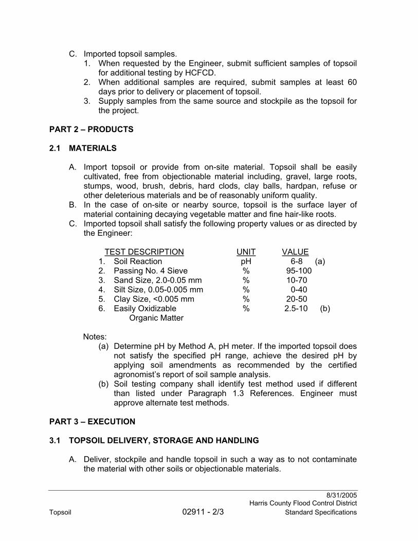
8/31/2005 Harris County Flood Control District Topsoil 02911 - 2/3 Standard Specifications
C. Imported topsoil samples. 1. When requested by the Engineer, submit sufficient samples of topsoil
for additional testing by HCFCD. 2. When additional samples are required, submit samples at least 60
days prior to delivery or placement of topsoil. 3. Supply samples from the same source and stockpile as the topsoil for
the project. PART 2 – PRODUCTS 2.1 MATERIALS
A. Import topsoil or provide from on-site material. Topsoil shall be easily cultivated, free from objectionable material including, gravel, large roots, stumps, wood, brush, debris, hard clods, clay balls, hardpan, refuse or other deleterious materials and be of reasonably uniform quality.
B. In the case of on-site or nearby source, topsoil is the surface layer of material containing decaying vegetable matter and fine hair-like roots.
C. Imported topsoil shall satisfy the following property values or as directed by the Engineer: TEST DESCRIPTION UNIT VALUE
1. Soil Reaction pH 6-8 (a) 2. Passing No. 4 Sieve % 95-100 3. Sand Size, 2.0-0.05 mm % 10-70 4. Silt Size, 0.05-0.005 mm % 0-40 5. Clay Size, <0.005 mm % 20-50 6. Easily Oxidizable % 2.5-10 (b) Organic Matter
Notes:
(a) Determine pH by Method A, pH meter. If the imported topsoil does not satisfy the specified pH range, achieve the desired pH by applying soil amendments as recommended by the certified agronomist’s report of soil sample analysis.
(b) Soil testing company shall identify test method used if different than listed under Paragraph 1.3 References. Engineer must approve alternate test methods.
PART 3 – EXECUTION 3.1 TOPSOIL DELIVERY, STORAGE AND HANDLING
A. Deliver, stockpile and handle topsoil in such a way as to not contaminate the material with other soils or objectionable materials.
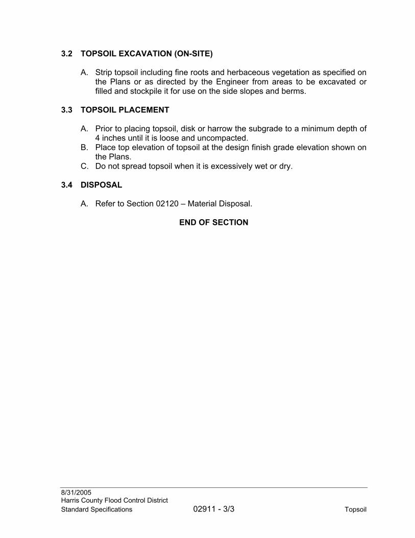
8/31/2005 Harris County Flood Control District Standard Specifications 02911 - 3/3 Topsoil
3.2 TOPSOIL EXCAVATION (ON-SITE)
A. Strip topsoil including fine roots and herbaceous vegetation as specified on the Plans or as directed by the Engineer from areas to be excavated or filled and stockpile it for use on the side slopes and berms.
3.3 TOPSOIL PLACEMENT
A. Prior to placing topsoil, disk or harrow the subgrade to a minimum depth of 4 inches until it is loose and uncompacted.
B. Place top elevation of topsoil at the design finish grade elevation shown on the Plans.
C. Do not spread topsoil when it is excessively wet or dry.
3.4 DISPOSAL
A. Refer to Section 02120 – Material Disposal.
END OF SECTION

8/31/2005 Harris County Flood Control District Standard Specifications 02921 - 1/6 Turf Establishment
SECTION 02921
TURF ESTABLISHMENT
PART 1 – GENERAL 1.1 SUMMARY
A. Section includes requirements for preparation of the seedbed and planting of turfgrass.
1.2 MEASUREMENT AND PAYMENT
A. Measurement and payment is as noted on the Unit Price Schedule. B. Refer to Section 01270 – Measurement and Payment for unit price
procedures. C. Areas with existing turfgrass cover not disturbed under this Contract,
channel bottoms and areas not requiring turf establishment will not be paid for.
D. Areas beyond limits of the construction work which are disturbed due to the Contractor’s techniques, access and related activities are not included in the measurement and are incidental.
E. Irrigation will be paid for per Section 02940 – Irrigation. F. Sod rolls greater than 24 inches wide will be paid for as 24 inch wide sod
unless shown otherwise on the Plans. PART 2 – PRODUCTS 2.1 SOD
A. Refer to Section 02922 – Sod. 2.2 SEED
A. Refer to Section 02923 – Seed. 2.3 MULCH AND TACKIFIER
A. Refer to Section 02925 – Mulch and Tackifier. 2.4 FERTILIZER
A. Refer to Section 02936 – Fertilizer.
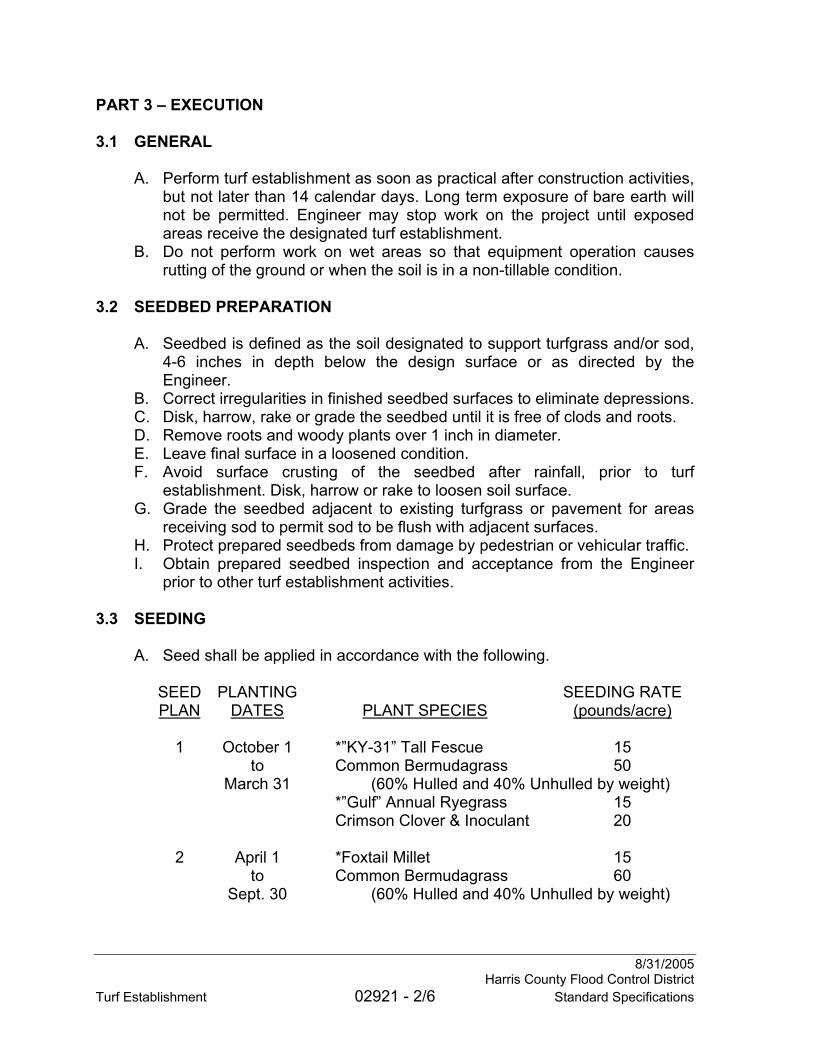
8/31/2005 Harris County Flood Control District Turf Establishment 02921 - 2/6 Standard Specifications
PART 3 – EXECUTION 3.1 GENERAL
A. Perform turf establishment as soon as practical after construction activities, but not later than 14 calendar days. Long term exposure of bare earth will not be permitted. Engineer may stop work on the project until exposed areas receive the designated turf establishment.
B. Do not perform work on wet areas so that equipment operation causes rutting of the ground or when the soil is in a non-tillable condition.
3.2 SEEDBED PREPARATION
A. Seedbed is defined as the soil designated to support turfgrass and/or sod, 4-6 inches in depth below the design surface or as directed by the Engineer.
B. Correct irregularities in finished seedbed surfaces to eliminate depressions. C. Disk, harrow, rake or grade the seedbed until it is free of clods and roots. D. Remove roots and woody plants over 1 inch in diameter. E. Leave final surface in a loosened condition. F. Avoid surface crusting of the seedbed after rainfall, prior to turf
establishment. Disk, harrow or rake to loosen soil surface. G. Grade the seedbed adjacent to existing turfgrass or pavement for areas
receiving sod to permit sod to be flush with adjacent surfaces. H. Protect prepared seedbeds from damage by pedestrian or vehicular traffic. I. Obtain prepared seedbed inspection and acceptance from the Engineer
prior to other turf establishment activities. 3.3 SEEDING
A. Seed shall be applied in accordance with the following.
SEED PLANTING SEEDING RATE PLAN DATES PLANT SPECIES (pounds/acre) 1 October 1 *”KY-31” Tall Fescue 15 to Common Bermudagrass 50 March 31 (60% Hulled and 40% Unhulled by weight) *”Gulf” Annual Ryegrass 15 Crimson Clover & Inoculant 20
2 April 1 *Foxtail Millet 15 to Common Bermudagrass 60 Sept. 30 (60% Hulled and 40% Unhulled by weight)

8/31/2005 Harris County Flood Control District Standard Specifications 02921 - 3/6 Turf Establishment
SEED PLANTING SEEDING RATE PLAN DATES PLANT SPECIES (pounds/acre) 3 April 1 *Foxtail Millet 15 to Hulled Common Bermudagrass 60
Sept. 30 “Pensacola” Bahiagrass 15 4 As Directed Hulled Common Bermudagrass 50 5 As Directed Crimson Clover & Inoculant 20
6 As Directed “Gulf” Annual Ryegrass 30
7 As Directed *“KY-31” Tall Fescue 15 Common Bermudagrass 50 (60% Hulled and 40% Unhulled by weight) Winter Wheat or Winter Oats 10 Crimson Clover & Inoculant 20 8 As Directed Green Sprangletop 3 Sideoats Grama Grass 5 Wildrye 8 Little Bluestem 8 Lovegrass 2 Three-awn 4
* Indicates MAXIMUM APPLICATION RATE ALLOWED.
B. Planting dates are approximate. Engineer will determine which Seed Plan to use prior to the start of seeding.
C. Seed Plan 1 is used when the average maximum daylight air temperature for the preceding two calendar weeks is less than 75 degrees F.
D. Seeding rate is for “Pure Live Seed (PLS).” Percentage of purity, germination and dormant seeds, as shown on the seed tag, shall be used to determine the actual application rate of bulk material to obtain required amount of PLS per acre. PLS = (%germination + %dormant seed) x %purity.
E. Seed Plans 4-8 are used only when shown on the Plans or when directed by the Engineer.
3.4 PLANTING METHODS
A. Method of planting is as noted on the Unit Price Schedule, on the Plans or as directed by the Engineer.
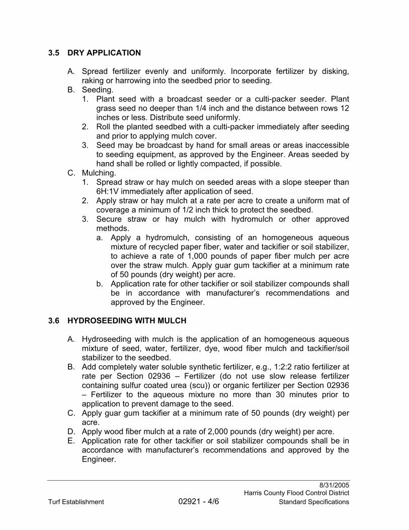
8/31/2005 Harris County Flood Control District Turf Establishment 02921 - 4/6 Standard Specifications
3.5 DRY APPLICATION
A. Spread fertilizer evenly and uniformly. Incorporate fertilizer by disking, raking or harrowing into the seedbed prior to seeding.
B. Seeding. 1. Plant seed with a broadcast seeder or a culti-packer seeder. Plant
grass seed no deeper than 1/4 inch and the distance between rows 12 inches or less. Distribute seed uniformly.
2. Roll the planted seedbed with a culti-packer immediately after seeding and prior to applying mulch cover.
3. Seed may be broadcast by hand for small areas or areas inaccessible to seeding equipment, as approved by the Engineer. Areas seeded by hand shall be rolled or lightly compacted, if possible.
C. Mulching. 1. Spread straw or hay mulch on seeded areas with a slope steeper than
6H:1V immediately after application of seed. 2. Apply straw or hay mulch at a rate per acre to create a uniform mat of
coverage a minimum of 1/2 inch thick to protect the seedbed. 3. Secure straw or hay mulch with hydromulch or other approved
methods. a. Apply a hydromulch, consisting of an homogeneous aqueous
mixture of recycled paper fiber, water and tackifier or soil stabilizer, to achieve a rate of 1,000 pounds of paper fiber mulch per acre over the straw mulch. Apply guar gum tackifier at a minimum rate of 50 pounds (dry weight) per acre.
b. Application rate for other tackifier or soil stabilizer compounds shall be in accordance with manufacturer’s recommendations and approved by the Engineer.
3.6 HYDROSEEDING WITH MULCH
A. Hydroseeding with mulch is the application of an homogeneous aqueous mixture of seed, water, fertilizer, dye, wood fiber mulch and tackifier/soil stabilizer to the seedbed.
B. Add completely water soluble synthetic fertilizer, e.g., 1:2:2 ratio fertilizer at rate per Section 02936 – Fertilizer (do not use slow release fertilizer containing sulfur coated urea (scu)) or organic fertilizer per Section 02936 – Fertilizer to the aqueous mixture no more than 30 minutes prior to application to prevent damage to the seed.
C. Apply guar gum tackifier at a minimum rate of 50 pounds (dry weight) per acre.
D. Apply wood fiber mulch at a rate of 2,000 pounds (dry weight) per acre. E. Application rate for other tackifier or soil stabilizer compounds shall be in
accordance with manufacturer’s recommendations and approved by the Engineer.

8/31/2005 Harris County Flood Control District Standard Specifications 02921 - 5/6 Turf Establishment
3.7 OVERSEEDING
A. Overseeding is the broadcast application of seed (per Seed Plan 4, 5 or 6) and fertilizer to an area with existing vegetation.
B. Mow site prior to overseeding at the direction of the Engineer. C. Lightly disk or harrow soil surface no more than 1 inch deep. D. Culti-pack area to cover seed with 1/4 inch of soil.
3.8 SODDING
A. Place sod in areas as shown on the Plans or as directed by the Engineer. B. Refer to Section 02922 – Sod. As a minimum:
1. Spread slow release fertilizer evenly and uniformly and incorporate by disking, harrowing or raking into the seedbed prior to placing sod.
2. Sod Panels. a. Place sod panels tightly against each other in rows. b. Stagger lateral joints. Exercise care to ensure the sod is not
stretched or overlapped and joints are butted tightly with no spaces between strips.
c. Place a minimum of 4 staples per sod panel. 3. Sod Rolls.
a. Provide rolls 24 inches wide. Sod roll is equivalent to two rows of sod panels. Do not provide rolls wider than 24 inches unless shown otherwise on the Plans. For sod rolls greater than 24 inches wide, provide a staple plan for approval.
b. Exercise care to ensure the sod rolls are not stretched and joints are butted tightly with no spaces between roll ends.
c. Place staples every 24 inches along each side. Stagger staples on opposing sides by 12 inches. Place additional staples in corners at roll ends and at the center of each end.
d. Cut ends of sod rolls at 45 degree angle before placing adjacent rolls together.
4. Tamp or roll the sod after placement to ensure good contact with the seedbed.
5. Water sod during installation to prevent excessive moisture loss. 6. Immediately after installation of sod, remove extraneous clumps of sod
or soil on sod and rake or wash off plant remnants on sod or adjacent pavements.
C. Provide irrigation for a minimum of 60 days or as directed by the Engineer. 3.9 ACCEPTANCE AND CONTRACTOR’S RESPONSIBLITIES
A. Engineer will approve turf establishment when specified planting method is complete.
B. Replace dead sod panels for a period of 60 days after installation.

8/31/2005 Harris County Flood Control District Turf Establishment 02921 - 6/6 Standard Specifications
3.10 DISPOSAL
A. Refer to Section 02120 – Material Disposal.
END OF SECTION
8/312005 Harris County Flood Control District Standard Specifications 02922 - 1/2 Sod
SECTION 02922
SOD
PART 1 – GENERAL 1.1 SUMMARY
A. Section includes requirements for Bermudagrass or St. Augustinegrass sod and staples.
1.2 MEASUREMENT AND PAYMENT
A. No separate measurement and payment is made under this Section. Include the cost for the work under this Section in the related item listed on the Unit Price Schedule.
B. Measurement and payment is as noted on the Unit Price Schedule. C. Refer to Section 01270 – Measurement and Payment for unit price
procedures. 1.3 SUBMITTALS
A. Refer to Section 01330 – Submittals. B. Submit letter from sod grower attesting that sod is Bermudagrass or
“Raleigh” St. Augustinegrass. PART 2 – PRODUCTS 2.1 SOD
A. Provide live, growing Bermudagrass or “Raleigh” St. Augustinegrass sod, as required by the Engineer.
B. Provide dark green sod with a healthy vigorous system of dense, thickly matted roots throughout the soil of the sod for a minimum depth of 1 inch (+/- 1/4 inch), excluding top growth and thatch.
C. Provide sod that contains no more than 5 percent noxious weeds and other crop and weed contaminants.
D. Provide sod free of diseases and harmful insects. E. Cut sod in uniform panels or rolls. Broken panels or panels or rolls with torn
or uneven ends will not be accepted. F. Sod panels shall be strong enough to support their own weight and retain
size and shape when suspended vertically from a firm grasp on the upper 10 percent of the panel.
G. Harvest, deliver and install sod within a 36-hour period. Sod not planted within this time period must be inspected and approved by the Engineer prior to installation.

8/31/2005 Harris County Flood Control District Sod 02922 - 2/2 Standard Specifications
H. Sod that has been allowed to dry out by exposure to the sun and air is unacceptable and will be considered nonconforming.
2.2 STAPLES
A. Provide 6 inch x 1 inch x 6 inch, 11 gauge steel “u” staples. PART 3 – EXECUTION – Not used
END OF SECTION

8/31/2005 Harris County Flood Control District Standard Specifications 02923 - 1/2 Seed
SECTION 02923
SEED
PART 1 – GENERAL 1.1 SUMMARY
A. Section includes requirements for seed in support of turf establishment. 1.2 MEASUREMENT AND PAYMENT
A. No separate measurement and payment is made under this Section. Include cost for work under this Section in the related item listed on the Unit Price Schedule.
B. Measurement and payment is as noted on the Unit Price Schedule. C. Refer to Section 01270 – Measurement and Payment for unit price
procedures. 1.3 REFERENCES
A. Texas Seed and Plant Certification Act and Standards, Sections 21.9, 31.10 & 21.11.
B. U.S. Department of Agriculture Rules and Regulations – Federal Seed Act. 1.4 SUBMITTALS
A. Refer to Section 01330 – Submittal Procedures. B. Submit seed certification (copy of seed bag tag(s)).
1. Certification shall include common name; botanical name; percent by weight of each plant species; year of harvest; percent purity, germination and dormant seed; percent noxious weed content (maximum 1%); and date of certification.
PART 2 – PRODUCTS 2.1 MATERIAL
A. Provide seed that complies with the referenced standards in this Section. B. Provide seed bags with tags affixed for inspection in the field. Bags without
tags will be considered nonconforming. C. Seed shall be tested and certified by a commercial or State laboratory not
more than 9 months prior to the date of planting. D. Provide seed in clean, unopened and undamaged bags. E. Provide seeds containing no objectionable material, such as sticks, stems
and unthrashed seed heads, which will hinder proper distribution.

8/31/2005 Harris County Flood Control District Seed 02923 - 2/2 Standard Specifications
F. Seed that is wet, moldy, starting to germinate or otherwise damaged, will be considered nonconforming.
PART 3 – EXECUTION – Not used
END OF SECTION

8/31/2005 Harris County Flood Control District Standard Specifications 02925 - 1/2 Mulch and Tackifier
SECTION 02925
MULCH AND TACKIFIER
PART 1 – GENERAL 1.1 SUMMARY
A. Section includes requirements for mulch and tackifier or soil stabilizer in support of turf establishment.
1.2 MEASUREMENT AND PAYMENT
A. No separate measurement and payment is made under this Section. Include the cost for the work under this Section in the related item listed on the Unit Price Schedule.
B. Measurement and payment is as noted on the Unit Price Schedule. C. Refer to Section 01270 – Measurement and Payment for unit price
procedures. 1.3 SUBMITTALS
A. Refer to Section 01330 – Submittal Procedures. B. Submit product cut sheets for mulch and tackifier which clearly shows the
amount of tackifier to be used per pound of mulch. C. Submit product information for mulch. D. Submit product information for tackifier. E. Submit product information for soil stabilizer (if used) including application
rate for required duration (months). PART 2 – PRODUCTS 2.1 MULCH
A. Provide mulch products free of noxious weeds and foreign materials. B. Provide mulch free of mold and rot. C. Provide commercial quality paper mulch consisting of paper cellulose fiber
mulch made from post-consumer recovered paper materials such as Pro-Mat® or approved equal.
D. Provide commercial quality wood fiber mulch consisting of wood cellulose fiber mulch made from recovered wood materials such as Silva-Fiber® or approved equal.
E. Provide straw mulch of oat, rice or wheat stem or other straw as approved by the Engineer.
F. Provide hay mulch of prairie grass, Bermudagrass or other hay as approved by the Engineer.

8/31/2005 Harris County Flood Control District Mulch and Tackifier 02925 - 2/2 Standard Specifications
G. Provide screened, mature compost or other organic materials as approved by the Engineer.
2.2 TACKIFIER
A. Provide organic biodegradable tackifier manufactured from muciloids or guar gum.
2.3 SOIL STABILIZER
A. Use a soil stabilizer in place of the guar gum tackifier when shown on the Plans or as directed by the Engineer. Soil stabilizers include products such as SoilMaster-WR®, Soil Sement®, UltraBond 2000® or approved equal.
PART 3 – EXECUTION – Not used
END OF SECTION

8/31/2005 Harris County Flood Control District Standard Specifications 02936 - 1/3 Fertilizer
SECTION 02936
FERTILIZER
PART 1 – GENERAL 1.1 SUMMARY
A. Section includes requirements for fertilizer in support of turf establishment. 1.2 MEASUREMENT AND PAYMENT
A. No separate measurement and payment is made under this Section. Include cost for work under this Section in the related item listed on the Unit Price Schedule.
B. Measurement and payment is as noted on the Unit Price Schedule. C. Refer to Section 01270 – Measurement and Payment for unit price
procedures. 1.3 REFERENCES
A. Texas Department of Agriculture – Fertilizer Laws. B. Association of Official Analytical Chemists – Fertilizer Content Analytical
Methods. C. 40 CFR Part 503.
1.4 SUBMITTALS
A. Refer to Section 01330 – Submittal Procedures. B. Submit results of agronomic soil testing of topsoil to Engineer for approval,
if available. 1.5 DELIVERY, STORAGE AND HANDLING
A. Deliver fertilizer in bags or containers clearly labeled with name and address of the manufacturer, weight and guaranteed analysis. Bulk fertilizer, if approved by the Engineer, must be accompanied by an invoice or label with the name and address of the manufacturer and guaranteed analysis and appropriate means to accurately measure and record weight of fertilizer used.
B. Deliver fertilizer in clean, unopened and undamaged bags.
8/31/2005 Harris County Flood Control District Fertilizer 02936 - 2/3 Standard Specifications
PART 2 – PRODUCTS 2.1 FERTILIZER
A. Turf Establishment – Planting Methods: Dry Application, Overseeding, and Sodding: 1. Provide pelleted or granulated fertilizer which has the specified
analysis packaged in 40 pound bags. 2. The guaranteed analysis represents the percent nitrogen (total N),
percent water insoluble nitrogen (where applicable), percent phosphate (citrate soluble P as P2O5) and percent potash (water soluble K as K2O) nutrients as determined by the methods of the Association of Official Analytical Chemists.
3. Synthetic Fertilizer. a. Use a complete fertilizer with an analysis ratio of 1:2:2 (N:P:K),
such as 10:20:20 with 50% of the nitrogen from sulfur coated urea (scu), or as directed by the Engineer.
4. Organic Fertilizer. a. Use Ag-Org P/L® organic fertilizer or approved equal, when
directed by the Engineer. b. Provide fertilizer containing a minimum N:P:K of 4:2:2 that is
manufactured by organic processes applied to the base ingredient – uncomposted chicken litter.
c. Fertilizer shall consist of approximately 89.5% insoluble and 10.5 soluble nitrogen.
d. Provide fertilizer containing at least the following amounts per dry ton derived from its base material without supplemental inclusions or additions: phosphorus (P) 23,000 ppm; potassium (K) 108,000 ppm; sulfur (S) 6,200 ppm; chloride (Cl-) 9,700 ppm; calcium (Ca) 28,000 ppm; sodium (Na) 6,400; iron (Fe) 2,000 ppm; copper (Cu) 470 ppm; magnesium (Mg) 7,600 ppm; manganese (Mn) 440 ppm; and zinc (Zn) 210 ppm.
e. Do not exceed acceptable levels of metals listed in 40 CFR Part 503 for fertilizer. Fertilizer must be guaranteed by manufacturer as non-burning.
B. . Turf Establishment – Hydroseeding with Mulch: 1. Use a completely soluble synthetic fertilizer or an organic fertilizer as
directed by the Engineer. 2. Use a complete synthetic fertilizer with an analysis ratio of 1:2:2
(N:P:K), such as 10:20:20 or an organic fertilizer with an analysis of 4:2:2 (N:P:K) as directed by the Engineer.
C. Reject fertilizer containing objectionable material that may hinder proper distribution.
D. Use dry and free-flowing fertilizer. Caked fertilizer will be considered nonconforming.

8/31/2005 Harris County Flood Control District Standard Specifications 02936 - 3/3 Fertilizer
PART 3 – EXECUTION 3.1 APPLICATION
A. Refer to Section 02921 – Turf Establishment. B. Apply synthetic fertilizer at a rate of 40 pounds Nitrogen/acre, which is 400
pounds fertilizer/acre of 10:20:20 or apply an organic fertilizer at a rate of 500 pounds fertilizer/acre of 4:2:2 as directed by the Engineer.
END OF SECTION

8/31/2005 Harris County Flood Control District Standard Specifications 02938 - 1/2 Mowing
SECTION 02938
MOWING
PART 1 – GENERAL 1.1 SUMMARY
A. Section includes requirements for mowing operations in support of turf establishment.
1.2 MEASUREMENT AND PAYMENT
A. Where there is not a separate item listed on the Unit Price Schedule for work of this Section, no separate measurement and payment is made. Include cost for work under this Section in the related item listed on the Unit Price Schedule.
B. Measurement and payment is as noted on the Unit Price Schedule. C. Refer to Section 01270 – Measurement and Payment for unit price
procedures. PART 2 – PRODUCTS – Not used PART 3 – EXECUTION 3.1 GENERAL
A. Mow areas including the top of berm, from right-of-way to top of slope, channel side slopes and channel bottom.
B. Mowing cycles shall be continuous unless written approval from the Engineer is obtained.
C. Adjust mower cutting height to no less than 6 inches. D. For mowing prior to overseeding, mowers shall be adjusted to the minimum
cutting height of the equipment. E. Mower operators shall establish a cutting path to traverse 100 per cent of
the designated area. Recut missed stands of vegetation or areas not uniformly cut at no additional cost to the District.
F. Mowing of heavy brush with stems up to 3 inches in diameter may be required in areas of dense vegetation.
G. In dry conditions, cut all vegetation in the bottom of the channel. Cut vegetation adjacent to wet areas from the toe line extending a minimum of 2 feet into the channel bottom, if deemed necessary by the Engineer.
H. Do not mow when soil conditions cannot support the weight of the equipment and mowing causes rutting of the soil or slope instability.
8/31/2005 Harris County Flood Control District Mowing 02938 - 2/2 Standard Specifications
I. Cut or remove vegetation around drainage interceptor structures and outfall pipes and surrounding bridge guardrails, pilings and other obstructions where mowers are unable to cut at no additional cost to the District. Leave a 6 inch vegetated buffer zone along fence lines and around trees to avoid damage.
J. Do not leave equipment within 30 feet of streets during non-working hours. Materials and/or equipment stored on-site shall be stored in an orderly manner.
K. Repair damage caused by the mowing operation at no additional cost to the District.
3.2 FIELD QUALITY CONTROL
A. Notify the Engineer, in writing, 5 working days prior to starting a mowing cycle.
B. Notify the Engineer at the completion of each mowing cycle for an inspection of the finished site.
3.3 EQUIPMENT
A. Use mower decks equipped with safety chains to prevent damage to property from flying debris.
B. Use sickle or line trimmer equipment for removing vegetation and debris from around bridges, culverts, guardrails, fences, poles or other obstructions not easily accessible with large mowing equipment.
C. Use mowing equipment in good operating condition and maintained to provide a clean, sharp cut of vegetation.
3.4 CLEANUP
A. Refer to Section 02120 – Material Disposal.
END OF SECTION
8/31/2005 Harris County Flood Control District Standard Specifications 02940 - 1/2 Irrigation
SECTION 02940
IRRIGATION
PART 1 – GENERAL 1.1 SUMMARY
A. Section includes requirements for temporary irrigation in support of turf establishment.
1.2 MEASUREMENT AND PAYMENT
A. Measurement and payment is as noted on the Unit Price Schedule. B. Refer to Section 01270 – Measurement and Payment for unit price
procedures. C. The minimum time period for irrigation payment is one month.
1.3 SUBMITTALS
A. Refer to Section 01330 – Submittal Procedures. B. Submit an irrigation plan prior to the start of work. As a minimum the
irrigation plan shall include: 1. Proposed method of irrigation. 2. Layout of irrigation pipes, sprinklerheads, related equipment and
location of irrigation water supply. 3. Source of irrigation water supply. 4. Evidence of approval from local water authorities to connect to potable
water system. 5. Pressure versus flowrate plotted curves for each field source of
irrigation water including, but not limited to, fire hydrant statistics. 6. Irrigation system information including supplier, backflow prevention
device and related attached devices. 7. Proposed watering schedule. 8. Planned vehicular access route.
C. Submit water meter logs and/or water invoices to support each application for payment.
PART 2 – PRODUCTS – Not used PART 3 – EXECUTION 3.1 GENERAL
A. Utilize watering equipment that provides a uniform water distribution and a controllable rate of water application.
8/31/2005 Harris County Flood Control District Irrigation 02940 - 2/2 Standard Specifications
B. Install the irrigation system per manufacturer’s recommendations. C. For projects less than 5 acres, the use of a water truck or hydromulching
equipment, rather than a temporary stationary irrigation system, is acceptable when approved by the Engineer.
D. Irrigate at intervals to promote and sustain vegetation. Prevent wilting of vegetation through proper water application frequency and quantity.
E. Implement frequent, shorter applications of water immediately following seeding and germination to ensure growth.
F. Distribute irrigation water evenly across the irrigated area. G. Utilize sprinkler heads that apply a fine, even spray over irrigated area. H. Avoid watering impervious surfaces, including but not limited to, concrete
paving, roadways and buildings. I. Avoid irrigation practices that create run-off, build-up of hydrostatic
pressures behind structures or ponding of water. 3.2 SITE ACCESS
A. Maintain vehicular access throughout the site during progress of the work. Protect irrigation pipes crossing top of berms and access roads.
3.3 TERMINATION OF IRRIGATION
A. Once irrigation commences, continue irrigation according to this Section for a minimum of 60 days or until instructed by the Engineer to discontinue and remove the irrigation system.
3.4 DAMAGE REPAIR
A. Repair damage caused by the irrigation operation at no cost to the District.
END OF SECTION

8/31/2005 Harris County Flood Control District Standard Specifications 02941 - 1/3 Herbicide Application
SECTION 02941
HERBICIDE APPLICATION
PART 1 - GENERAL 1.1 SUMMARY
A. Section includes requirements for application of herbicide to control undesirable weeds, brush and trees.
1.2 MEASUREMENT AND PAYMENT
A. Where there is not a separate item listed on the Unit Price Schedule for work in this Section, no separate measurement and payment is made. Include cost for work under this Section in the related item listed on the Unit Price Schedule.
B. Measurement and payment is as noted on the Unit Price Schedule. C. Refer to Section 01270 – Measurement and Payment for unit price
procedures. 1.3 SUBMITTALS
A. Refer to Section 01330 – Submittal Procedures. B. Submit the following prior to the start of work:
1. Herbicide Application Plan clearly stating: a. Product(s). b. List of Application Regulatory Agencies. c. Scheduling Information. d. Herbicide Equipment. e. Mixing Rates. f. Application Rates. g. Method of Application. h. Location of Each Product to beApplied.
2. Copies of manufacturer’s labels, product data and Material Safety Data Sheets (MSDS) for all products to be used.
3. Applicator qualifications, as follows: a. Copy of the applicator company’s state business license. b. Copy of each current Certified Commercial Applicators License
and evidence of Applicator’s qualifications in required categories for work under this Contract.
1.4 APPLICATOR QUALIFICATIONS
A. Contractor must possess a Pest Control Commercial Business License.

8/31/2005 Harris County Flood Control District Herbicide Application 02941 - 2/3 Standard Specifications
B. Utilize spray applicators that hold a current Certified Commercial Applicators License and are qualified in required categories for applying herbicides in the State of Texas and Harris County.
1.5 HERBICIDE SPILLS
A. Report spills immediately to the Engineer and agencies as required by law. Use responsible care and means in clean up of spills and disposal of materials used to clean up spill.
B. Refer to Section 02120 – Material Disposal. PART 2 – PRODUCTS 2.1 MATERIAL
A. Provide a herbicide that assures the required control and is in compliance with all Federal, State and local requirements.
B. Acceptable products for herbicide application include Rodeo®, AquaMaster®, Plateau®, Round-Up® (Isopropylamine Salt of Glyphosate) or approved equal.
C. Provide a marker dye in the herbicide to easily identify treatment of cut stumps or other areas as directed by the Engineer.
PART 3 – EXECUTION 3.1 GENERAL
A. Apply herbicide in accordance with manufacturer’s product label, recommendations and MSDS.
B. Follow safety procedures and use safety equipment as required by regulatory agencies and as stated on manufacturer’s product information, recommendations and MSDS.
C. Apply herbicide only to areas as shown on the Plans or designated by the Engineer to control undesirable vegetation, including aquatic species. Areas of application may include parts or all of the channel rights-of-way, including the channel bottom, channel side slopes, berm and backslope swale.
D. Engineer will provide a list of vegetation to be controlled. E. Avoid application of herbicide to areas where desirable grasses or other
desirable vegetation is established. Replace desirable vegetation killed by herbicide application at no cost to the District.
3.2 CLEARING SITE
A. Apply herbicide within 2 hours of cutting tree and brush stumps. Re-cut stumps if application of herbicide is more than 2 hours after initial cutting.

8/31/2005 Harris County Flood Control District Standard Specifications 02941 - 3/3 Herbicide Application
B. Treat each stump individually to ensure proper application and dosage to control the target plant.
C. General area spraying of herbicides is not permitted. 3.3 HERBICIDE MIXTURES
A. Prepare chemical and water mixtures with potable water. B. Do not use water from drainage ditches and channels. C. Prepare only the amount of herbicide mixture required for immediate use.
3.4 PERFORMANCE
A. Clearing Projects: 1. Achieve 100 percent control of target species. 2. Re-cut and re-treat target species if new growth appears within 60
days of first application at no additional cost to the District. B. General Herbicide Usage:
1. Achieve at least 95 percent control of target species. 2. Control of target species shall be achieved 18 days after completion of
herbicide application or within approved manufacturer’s label time period.
3. If control has not been achieved, make additional applications within 15 days of request by Engineer until the required results have been achieved, at no additional cost to the District.
3.5 CLEAN UP AND DISPOSAL
A. Store or dispose of unused herbicide mixtures in accordance with current regulations and manufacturer’s recommendations.
B. Refer to Section 02120 – Material Disposal.
END OF SECTION
8/31/2005 Harris County Flood Control District Standard Specifications 03310 - 1/9 Concrete
SECTION 03310
CONCRETE
PART 1 – GENERAL 1.1 SUMMARY
A. Section includes requirements for cast-in-place concrete. 1.2 MEASUREMENT AND PAYMENT
A. Where there is not a separate item listed on the Unit Price Schedule for work in this Section, no separate measurement and payment is made. Include cost for work under this Section in the related item listed on the Unit Price Schedule.
B. Measurement and payment is as noted on the Unit Price Schedule. C. Refer to Section 01270 – Measurement and Payment for unit price
procedures. 1.3 REFERENCE
A. ACI 117 – Tolerances for Concrete Construction and Materials. B. ACI 211.1 – Selecting Proportions for Normal, Heavyweight and Mass
Concrete. C. ACI 214.3R – Simplified Version of the Recommended Practice for
Evaluation of Strength Test Results of Concrete. D. ACI 302.1R – Concrete Floor and Slab Construction. E. ACI 304R – Measuring, Mixing, Transporting, and Placing Concrete. F. ACI 305R – Hot Weather Concreting. G. ACI 308 – Curing Concrete. H. ACI 309R – Consolidation of Concrete. I. ACI 315 – Detailing Reinforced Concrete Structures. J. ACI 318 – Building Code Requirements for Reinforced Concrete. K. ASTM A 82 – Steel Wire, Plain, for Concrete Reinforcement. L. ASTM A 185 – Steel Welded Wire Reinforcement, Plain, for Concrete. M. ASTM A 615 – Deformed and Plain Billet-Steel Bars for Concrete
Reinforcement. N. ASTM A 767 – Zinc-coated (Galvanized) Bars for Concrete
Reinforcement. O. ASTM A 775 – Epoxy-Coated Steel Reinforcing Bars. P. ASTM A 884 – Epoxy-Coated Steel Wire and Welded Wire
Reinforcement. Q. ASTM C 33 – Concrete Aggregates. R. ASTM C 94 – Ready-Mixed Concrete.

8/31/2005 Harris County Flood Control District Concrete 03310 - 2/9 Standard Specifications
S. ASTM C 138 – Unit Weight, Yield, and Air Content (Gravimetric) of Concrete.
T. ASTM C 143 – Slump of Hydraulic-Cement Concrete. U. ASTM C 150 – Portland Cement. V. ASTM C 172 – Sampling Freshly Mixed Concrete. W. ASTM C 173 – Air Content of Freshly Mixed Concrete by Volumetric
Method. X. ASTM C 231 – Air Content of Freshly Mixed Concrete by Pressure
Method. Y. ASTM C 260 – Air-Entraining Admixtures for Concrete. Z. ASTM C 309 – Liquid Membrane-Forming Compounds for Curing
Concrete. AA. ASTM C 494 – Chemical Admixtures for Concrete. BB. ASTM C 595 – Blended Hydraulic Cements. CC. ASTM C 685 – Concrete Made by Volumetric Batching and Continuous
Mixing. DD. ASTM C 1077 – Laboratories Testing Concrete and Concrete Aggregates
for Use in Construction and Criteria for Laboratory Evaluation.
EE. CPMB-100 – Concrete Plant Standards, Part 2 – Plant Control Systems.
FF. CRSI – Placing Reinforcing Bars. GG. CRSI MSP-1 – Manual of Standard Practice.
1.4 SUBMITTALS
A. Refer to Section 01330 – Submittal Procedures. B. Submit proposed mix design and strength test data for each type and
strength of concrete used. C. Submit laboratory reports prepared by an independent testing laboratory
verifying that materials used comply with the requirements of this Section. D. Provide manufacturer’s mill certificates for reinforcing steel for inspection in
the field. Steel not accompanied by manufacturer’s mill certificates will not be approved. Provide specimens for testing when required by Engineer.
E. Provide batch tickets showing mix design number and the information required by ASTM C 94 for ready-mixed concrete delivered to the site. Provide batch tickets showing the information required by ASTM C 685 for concrete produced by continuous mixing.
F. Submit certification from concrete supplier that materials and equipment used to produce and deliver concrete comply with this Section.
G. Submit Shop Drawings in accordance with ACI 315 and ACI 318, when required, showing reinforcement type, quantity, size, length, location, spacing, bending, splicing, support, fabrication details and other pertinent information.
H. For waterstops, submit product information, including manufacturer’s description literature, installation instructions and specifications.

8/31/2005 Harris County Flood Control District Standard Specifications 03310 - 3/9 Concrete
I. Submit curing procedures including materials and equipment to be used. 1.5 HANDLING AND STORAGE
A. Reinforcing Steel: Store reinforcing steel to protect it from damage and formation of excessive rust. Protect epoxy-coated steel from damage to the coating.
PART 2 – PRODUCTS 2.1 CONCRETE MATERIALS
A. Cementitious Material: 1. Portland Cement: ASTM C 150, TypeI/II or II, unless the use of Type III
is authorized by Engineer; or ASTM C 595, Type IP. For concrete in contact with sewage, use Type II cement.
2. When aggregates are potentially reactive with alkalis in cement, use cement not exceeding 0.6 percent alkali content in the form of Na2O + 0.658 K2O.
B. Water: Clean, free from harmful amounts of oils, acids, alkalis or other deleterious substances and meeting requirements of ASTM C 94.
C. Aggregate: 1. Coarse Aggregate: ASTM C 33. Unless otherwise indicated, use the
following ASTM standard sizes: No. 357 or No. 467; No. 57 or No. 67, No. 7. Maximum size: Not larger than 1/5 of the minimum dimension between sides of forms, nor larger than 3/4 of minimum clear spacing between reinforcing bars.
2. Fine Aggregate: ASTM C 33. 3. Determine the potential reactivity of fine and coarse aggregate in
accordance with the Appendix to ASTM C 33. D. Air Entraining Admixtures: ASTM C 260. E. Chemical Admixtures:
1. Water Reducers: ASTM C 494, Type A. 2. Water Reducer and Retarder: ASTM C 494, Type D. 3. High Range Water Reducer (Superplasticizer): ASTM C 494, Types F
and G. F. Prohibited Admixtures: Admixtures containing calcium chloride,
thiocyanate, or materials that contribute free chlorine ions in excess of 0.1 percent by weight of cement.
G. Reinforcing Steel: 1. Use new billet steel bars conforming to ASTM A 615, ASTM A 767, or
ASTM A 775, grade 40 unless otherwise shown on Plans. Use deformed bars except where smooth bars are specified. When placed in work, keep steel free of dirt, scale, loose or flaky rust, paint, oil or other harmful materials.
2. Where shown, use welded wire fabric with wire conforming to

8/31/2005 Harris County Flood Control District Concrete 03310 - 4/9 Standard Specifications
ASTM A 185 or ASTM A 884. Supply the gauge and spacing shown, with longitudinal and transverse wires electrically welded together at points of intersection with welds strong enough not to be broken during handling or placing.
3. Wire: ASTM A 82. Use 16-1/2 gauge minimum for tie wire unless otherwise shown on the Plans.
H. Curing Compounds: Liquid membrane-forming compounds conforming to ASTM C 309, with white or other heat reflecting pigment.
2.2 FORMWORK MATERIALS
A. Lumber and Plywood: Seasoned and of good quality, free from loose or unsound knots, knot holes, twists, shakes, decay and other imperfections which would affect strength or impair the finished surface of concrete. Use S4S lumber for facing and sheathing.
B. Formwork: For exposed concrete indicated to receive rubbed finish, provide form or form-lining surfaces free of irregularities.
C. Form Ties: Metal or fiberglass of approved type with tie holes not larger than 7/8 inch in diameter.
D. Metal Forms: Clean and in good condition, free from dents and rust, grease or other foreign material that tend to mar or discolor concrete, in a gauge and condition capable of supporting concrete and construction loads without significant distortion. Countersink bolt and rivet heads on facing sides. Use only metal forms which present a smooth surface and which line up properly.
2.3 PRODUCTION METHODS
A. Use either ready-mixed concrete conforming to requirements of ASTM C 94 or concrete produced by volumetric batching and continuous mixing in accordance with ASTM C 685.
2.4 MEASUREMENT OF MATERIALS
A. Measure dry materials by weight, except volumetric proportioning may be used when concrete is batched and mixed in accordance with ASTM C 685.
B. Measure water and liquid admixtures by volume. 2.5 DESIGN MIX
A. Use design mixes prepared by a certified testing laboratory in accordance with ASTM C 1077 and conforming to requirements of this Section.
B. Proportion concrete materials based on ACI 211.1 to comply with durability and strength requirements of ACI 318, Chapters 4 and 5, and this Section.
C. Proportioning on the basis of field experience or trial mixtures in

8/31/2005 Harris County Flood Control District Standard Specifications 03310 - 5/9 Concrete
accordance with the requirements of Section 5.3 of ACI 318 may be used, if approved by Engineer.
D. Classification:
Type
Minimum 28-Day
Compressive Strength
(Lbs./sq.in.)
Maximum W/C Ratio
Air Content
(Percent)
Consistency
Range in Slump
(Inches)
Cementitious Content (Lbs./cy)
Structural 3000 0.55 3-5 2 to 4 470
Non-Structural 1500 n/a 3-5 5 to 7 329
E. Determine air content in accordance with ASTM C 138, ASTM C 173 or ASTM C 231.
F. Use of Concrete Types: Use types of concrete as indicated on the Plans Unless indicated otherwise on the Plans or Specifications, use non-structural, unreinforced concrete for pipe plugs, seal slabs, thrust blocks, trench dams and concrete fill; use structural, reinforced concrete for all other applications.
PART 3 – EXECUTION 3.1 FORMS AND SHORING
A. Install forms in accordance with ACI 304R. B. Provide mortar-tight forms sufficient in strength to prevent bulging between
supports. Set and maintain forms to lines designated such that finished dimensions of structures are within the tolerances specified in ACI 117. Construct forms to permit removal without damage to concrete. Provide adequate cleanout openings. Before placing concrete, remove extraneous matter from within forms.
C. Unless otherwise indicated, form outside corners and edges with triangular 3/4-inch chamfer strips (measured on sides).
D. Remove metal form ties to depth of at least 3/4 inch from surface of concrete. Do not use pipe spreaders. Remove spreaders which are separate from forms as concrete is being placed.
E. Immediately before the concrete is placed, wet surface of forms which will come in contact with concrete.
3.2 PLACING REINFORCEMENT
A. Place reinforcing steel as shown on the Plans. Secure steel in position in forms to prevent misalignment. Welding of reinforcing steel is not permitted unless noted on the Plans. Maintain reinforcing steel in place using approved concrete, hot-dip galvanized metal or plastic chairs and spacers. Place reinforcing steel in accordance with CRSI Publication “Placing Reinforcing Bars.” Request inspection of reinforcing steel by Engineer
8/31/2005 Harris County Flood Control District Concrete 03310 - 6/9 Standard Specifications
before concrete is placed. B. Minimum spacing center-to-center of parallel bars: 2-1/2 times nominal bar
diameter. Minimum cover measured from surface of concrete to face of reinforcing bar unless shown otherwise on the Plans: 2 inches.
C. Detail bars in accordance with ACI 315. Provide reinforcing steel fabricated in accordance with CRSI Publication MSP-1, “Manual of Standard Practice.” Bend reinforcing steel to required shape while steel is cold. Do not overbend steel.
D. Provide splice and development length of bars as shown on Plans. Stagger splices or locate at points of low tensile stress.
3.3 EMBEDDED ITEMS
A. Install conduit and piping as shown on the Plans. Locate and fasten conduit, piping and other embedded items in forms.
3.4 BATCHING, MIXING AND DELIVERY OF CONCRETE
A. Measure, batch, mix and deliver ready-mixed concrete in accordance with ASTM C 94 and ACI 304R. Produce ready-mixed concrete using an automatic batching system as described in CPMB-100 Concrete Plant Standards, Part 2 – Plant Control Systems.
B. Measure, mix and deliver concrete produced by volumetric batching and continuous mixing in accordance with ASTM C 685.
C. Maintain concrete workability without segregation of material and excessive bleeding. Obtain approval of Engineer before adjustment and change of mix proportions.
D. Do not exceed the maximum water-cement ratio of the approved mix design. If all water allowed by the water-cement ratio has not been added at the start of mixing, the remaining water may be added no later than the time of delivery. Addition of water should be in accordance with ASTM C 94.
E. Do not mix concrete when the air temperature is at or below 40 degrees F and falling. Concrete may be mixed when temperature is 35 degrees F and rising. Take temperature readings in the shade, away from artificial heat. Protect concrete from temperatures below 32 degrees F until the concrete has cured for a minimum of 3 days at 70 degrees F or 5 days at 50 degrees F.
F. Conform to ACI 305R for batching concrete when air temperature is above 90 degrees F.
G. Clean, maintain and operate equipment so that it thoroughly mixes material.
H. Mixing methods other than as described above shall be used only when approved by Engineer.
8/31/2005 Harris County Flood Control District Standard Specifications 03310 - 7/9 Concrete
3.5 PLACING CONCRETE
A. Place and consolidate in accordance with ACI 304R and ACI 309R. B. Give at least 24 hours advance notice to Engineer to permit inspection of
forms, reinforcing steel, embedded items and other preparations for placing concrete. Place no concrete prior to Engineer’s inspection.
C. Schedule concrete placing to permit completion of finishing operations in daylight hours. However, if necessary to continue after daylight hours, light the site as required. If rainfall occurs after placing operations are started, provide covering to protect the work.
D. Use troughs, pipes and chutes lined with approved metal or synthetic material. Place concrete without allowing segregation. Keep chutes, troughs and pipes clean and free from coatings of hardened concrete. Do not allow aluminum material to be in contact with concrete.
E. Limit free fall of concrete to prevent segregation. Do not deposit large quantities of concrete at one location so that running or working concrete along forms is required. Do not jar forms after concrete has taken on initial set; do not place any strain on projecting reinforcement or anchor bolts.
F. Use tremies for placing concrete in walls and similar narrow or restricted locations. Use tremies made in sections, provide in several lengths, so that outlet may be adjusted to proper height during placement operations.
G. When the weather is hot enough to cause the concrete temperature to exceed 90 degrees F, employ means, such as pre-cooling aggregates and mixing water, using ice or placing at night, to maintain concrete temperature below 90 degrees F.
H. Consolidate each layer of concrete with concrete spading implements and mechanical vibrators of type and adequate number for the size of placement. Apply vibrators to concrete immediately after depositing. Do not use vibrators to aid lateral flow of concrete. Do not over-consolidate concrete.
I. Handling and Placing Concrete: Conform to ACI 302.1R, ACI 304R and ACI 309R.
3.6 CURING AND REMOVAL OF FORMS AND SHORING
A. Comply with ACI 308. Cure by preventing loss of moisture and rapid temperature change for a period of 7 days when Type I/II, II or IP cement has been used and for 3 curing days when Type III cement has been used.
B. Start curing as soon as free water has disappeared from the concrete surface after placing and finishing.
C. A curing day is any calendar day in which the temperature is above 50 degrees F for at least 19 hours. Colder days may be counted if air temperature adjacent to concrete is maintained above 50 degrees F. In continued cold weather, when artificial heat is not provided, removal of forms and shoring may be permitted at the end of calendar days equal to twice the required number of curing days.

8/31/2005 Harris County Flood Control District Concrete 03310 - 8/9 Standard Specifications
D. Formed surfaces not requiring rubbed-finished surface: 1. Cure by leaving forms in place for the full cure period or forms may be
removed after 2 days and curing compound applied. Keep wood forms wet during the curing period. Add water as needed for other types of forms.
2. Soffit Forms: Leave soffit forms and shores in place until concrete has reached the specified design strength unless otherwise directed by the Engineer.
E. Rubbed Finish: 1. At formed surfaces requiring rubbed finish, remove forms as soon as
practicable without damaging the surface. Remove forms from surfaces requiring rubbing only as rapidly as rubbing operation progresses. Remove forms from vertical surfaces not requiring rubbed finish when concrete has aged for the required number of curing days.
2. After rubbed-finish operations are complete, continue curing formed surfaces by using either approved curing/sealing compounds or moist cotton mats until normal curing period is complete.
F. Unformed Surfaces: Cure with approved membrane curing compound method in accordance with ASTM C 309. 1. After concrete has received a final finish and surplus water sheen has
disappeared, immediately seal surface with a uniform coating of approved curing compound, applied at the rate of coverage recommended by manufacturer or as directed by Engineer. Provide uniform coverage at a minimum rate of 1 gallon per 180 square feet of area.
2. Thoroughly agitate the compound during use and apply by means of approved mechanical power pressure sprayers equipped with atomizing nozzles. For application on small miscellaneous items, hand-powered spray equipment may be used. Prevent loss of compound between nozzle and concrete surface during spraying operations.
3. Do not apply compound to a dry surface. If concrete surface has become dry, thoroughly moisten surface immediately prior to application. At locations where coating shows discontinuities, pinholes or other defects, or if rain falls on a newly coated surface before film has dried sufficiently to resist damage, apply an additional coat of compound at the specified rate of coverage.
3.7 FINISHING
A. Patch honeycomb, minor defects and form tie holes in concrete surfaces with cement mortar mixed 1 part cement to 2 parts fine aggregate. Repair defects by removing unsatisfactory material and replacing with new concrete, keyed and bonded to existing concrete. Finish to provide a uniform surface between patches and existing concrete.

8/31/2005 Harris County Flood Control District Standard Specifications 03310 - 9/9 Concrete
B. Apply a broomed finish to all exposed surfaces of interceptor structure inlets and channel lining. Apply broomed finish in a single, continuous stroke perpendicular to flow to produce a uniform surface.
C. Apply a rubbed finish to all exposed surfaces unless directed otherwise on the Plans or by the Engineer. After pointing has set sufficiently, wet the surface and perform first surface rubbing with No. 16 carborundum stone or approved equal. Do not add cement to form surface paste. Rub sufficiently to bring surface to paste; to remove form marks and projections; and to produce a smooth, dense surface. Spread or brush material, which has been ground to paste, uniformly over surface and allow to reset. In preparation for final acceptance, clean surfaces and perform final finish rubbing with No. 30 carborundum stone or approved equal. After rubbing, allow paste on the surface to re-set; then wash surface with clean water. Leave structure with a clean, neat and uniform finish.
3.8 DEFECTIVE WORK
A. Remove and repair defective work at no cost to the District. B. If concrete surface is bulged, uneven, or shows honeycombing or form
marks which cannot be repaired satisfactorily through patching, remove and replace the defective work as directed by the Engineer.
C. Replace or repair pitted or washed concrete as directed by the Engineer. 3.9 TESTING AND INSPECTION
A. Refer to Section 01457 – Construction Tests and Inspection. 3.10 PROTECTION
A. Refer to Section 02316 – Structural Excavating and Backfilling. B. Provide for protection of freshly placed concrete against damage from
precipitation by having sufficient material on-site to protect finished surface. 3.11 MATERIAL DISPOSAL
A. Refer to Section 02120 – Material Disposal.
END OF SECTION

Articulating Concrete Block Details
Concrete Channel Lining Details
Interceptor Structure Details
Storm Sewer and Riprap Details
Stormwater Pollution Prevention Details
2005 Detail Sheets
9900 Northwest FreewayHouston, Texas 77092
713-684-4000www.hcfcd.org