august 2012 contents - : : acson international : : 9 water side treatment . 102 - 108 10 heating...
TRANSCRIPT
Mini Chiller Application Manual 2.0
Contents
Introduction ………………………………………………………........... 1 - 3
1 Chiller Mounting ………………………………………………….. 4 - 5
2 Water Pipe Circuit ………………………………………………… 6 - 24
3 Water Pipe and Fittings ………………………………………….. 25 - 61
4 Pipe and Fitting Size ……………………………………………... 62 - 67
5 Water Pump ………………………………………………………... 68- 81
6 Water Storage Tank and Expansion Tank ……………………. 82 - 87
7 Insulation Material ………………………………………………... 88 - 100
8 Pipe Support ………………………………………………………. 101
9 Water Side Treatment ……………………………………………. 102 - 108
10 Heating Operation ………………………………………………… 109 - 114
11 Electrical Wiring Control ………………………………………… 115 - 118
12 Flow Switch ………………………………………………………... 119 - 123
13 System Balancing ………………………………………………… 124 - 126
14 Chiller Shut Down ………………………………………………… 127
August 2012

Mini Chiller Application Manual 2.0
Introduction Page - 1 -
Introduction The air-cooled mini chillers form part of a complete integrated water hydronic system with the chiller water fan coil units. The conventional series with capacity ranging from 20,000 Btu/hr to 150,000 Btu/hr (5.86 – 43.96 kW) and the new inverter series ranging from 30,000 Btu/hr to 210,000 Btu/hr (8.79 – 61.49 kW) make them suitable for various applications:
- Office Rooms - Private Houses - Business Rooms - Club, Pubs, Coffee Houses - Hotels - Restaurants
The advantages of using these chillers are:
1. Due to its compact design, the mini-chillers require a smaller space for installation. It also allows for flexibility in design to meet various types of application requirements.
2. The amount of refrigerant used is small compared with other split and multi-split direct expansion systems, i.e. they are more environmental friendly.
3. There is no necessity to use cooling towers. 4. No refrigerant is used in the occupied space. 5. The usage of water as the cooling medium allows for excellent load variability with
minimal system complexity as against equivalent VRV systems. 6. Ability to have long piping distances.
The additional advantages of using the inverter mini chillers are:
1. Inverter system provides constant water temperature band; i.e. much lesser water temperature fluctuation. With this, there is no necessity to use buffer tank.
2. The inverter system allows variation of load depending on demand - providing high efficiency with cost and energy saving effect.
3. It reacts fast to cooling/heating at range beyond 30% of the dominant capacity. It has low starting surge and smooth/linear part loading with less start/stop.
A water hydronic system can be classified as a close or open system. Definition: A close water system is one with no more than one point of interface with a compressible gas or surface. [ASHRAE handbook: 1996 System & Equip.] The basic design of the mini-chiller is for a close system. However, a modification for an open system is possible.
The close hydronic system will consist of the following fundamental components:
a. Source b. Load c. Expansion Tank d. Pump e. Distribution System
Mini Chiller Application Manual 2.0
Introduction Page - 2 -
SOURCE LOAD
Distribution system
Pump
Expansion tank
Heat Heat
Heat LOAD
Pump
Expansion tank
Buffer water tank
BPHE
Compressor
Condenser
Distribution system
Heat
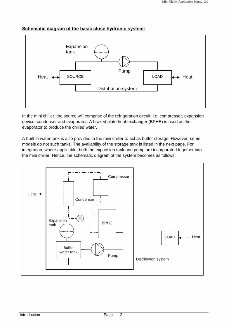
Schematic diagram of the basic close hydronic syste m:
In the mini chiller, the source will comprise of the refrigeration circuit, i.e. compressor, expansion device, condenser and evaporator. A brazed plate heat exchanger (BPHE) is used as the evaporator to produce the chilled water. A built-in water tank is also provided in the mini chiller to act as buffer storage. However, some models do not such tanks. The availability of the storage tank is listed in the next page. For integration, where applicable, both the expansion tank and pump are incorporated together into the mini chiller. Hence, the schematic diagram of the system becomes as follows:

Mini Chiller Application Manual 2.0
Introduction Page - 3 -
If both chilled water and hot water are required for the system, a mini chiller with a reverse cycle operation (i.e. heat pump cycle) will be used. The unit will have an additional 4-way valve, suction accumulator and liquid receiver for this purpose. It is by such integration of components of the hydronic system that the mini chiller becomes compact. Installation of the chiller will thus only involve:
1. The chiller mounting
2. Indoor fan coil unit installation
3. Water piping installation between the chiller and fan coil unit
4. Electrical wiring connection This manual is written with the purpose of providing guidelines as to the installation and operation of the hydronic system; i.e. both the chiller and fan coil unit. Application design guidelines will also be discussed. Selection criteria of piping, valve, pump and other equipment are also given. Examples of such complete installations are as shown in the following pages. This manual will give some technical information and details on how such installations are designed and done at site. In general, there are four C series of mini chillers available:
a. Conventional C series (from 20,000 Btu/hr [5.86 kW] to 60,000 Btu/hr [17.57 kW]) - monoblock design, with built-in buffer tank
b. Conventional C series (from 80,000 Btu/hr [23.45 kW] to 150,000 Btu/hr [43.96 kW])
- monoblock design, without buffer tank - with 0-50-100% part loading
c. Tandem C series (from 30,000 Btu/hr [8.79 kW] to 55,000 Btu/hr [16.10 kW])
- monoblock design, without buffer tank - with 0-40-100% and 0-60-100% part loading
d. Inverter C series (from 30,000 Btu/hr [8.79 kW] to 210,000 Btu/hr [61.49 kW])
- monoblock design, without buffer tank - with linear loading
This manual must be used in conjunction with the Technical Manual and Installation and Operation Manual (IOM) of the mini chillers and chilled water fan coil units.

Mini Chiller Application Manual 2.0
Section 1 Page - 4 -
Wall
Steel bracket
M10
Plinth
Concrete flooring
Plinth
Concrete flooring
Section 1: Chiller Mounting Care must be taken to locate the air-cooled chiller at the proper place. Ensure sufficient clearance around the unit to allow proper air flow and to facilitate access for maintenance. Location of the units must also prevent short-circuiting of the discharge air. Do not block any air passage in and out of the units. Please refer to the corresponding Technical Manual for further information. The chiller unit must be placed on a firm surface, e.g. concrete flooring, slab or plinth. Due to space consideration, the chiller may be mounted onto a steel bracket which is secured to a firm surface, e.g. brick wall, concrete wall or a steel structure.

Mini Chiller Application Manual 2.0
Section 1 Page - 5 -
Such brackets must have sufficient strength to carry the weight of the chiller unit. It is recommended that angle bars (e.g. 38mm*38mm*3mmt) or hollow section bars (e.g. 25mm*50m*2mmt) to be used for fabricating these brackets. These brackets must also allow clearance for removal of service panels for maintenance purposes.
In any case, it is vital that the chiller unit is secured firmly onto the concrete floor/slab or steel bracket by using studs, wall plugs or bolts/nuts at the four (4) mounting holes located at the base plate of the chiller. The weight of the chiller unit and the water pipe connections are not sufficient to prevent unit movement should any sudden impact or strong vibrations occur in the unit. Failure to do so may cause the water pipes to deform and break. It is further recommended that rubber isolation pads (1/2" thick) to be placed beneath each mounting hole to prevent excessive vibration and noise. If necessary, isolating springs can also be mounted. External drain pan In some instances, it is necessary to install an external drain pan beneath the unit to collect any condensate water from the chiller unit. This is especially so for the heat pump versions, where water will condense on the heat exchanger coil during the heating mode. Further more, a lot of water will flow out during the defrost cycle.
Such external drain pans are needed when the chiller units are installed inside a plant room where it is not appropriate for the floor to be wet.
It is recommended that the drain pan to be fabricated out of galvanized iron (GI) sheet metal, at least 0.8 mm in thickness. Allow the drain pan depth of about 20mm. This external drain pan should be laid out on the floor first before placing the entire chiller unit on top of it. It is recommended that the chiller unit to be raised up by 20 - 30mm from the drain pan so as to prevent rusting of the chiller base pan. Caution! Please ensure adequate ventilation in the plant room else the chiller unit may trip.
Mini Chiller Application Manual 2.0
Section 2 Page - 6 -
Water out
Expansion tank
Water in
Note: For series without buffer tank, the fundamentals of water piping circuitry Is still the same
MINI CHILLER UNIT
Buffer tank
LOAD FCU 1
LOAD FCU 2
LOAD FCU 3
LOAD FCU 4
Series Circuit:
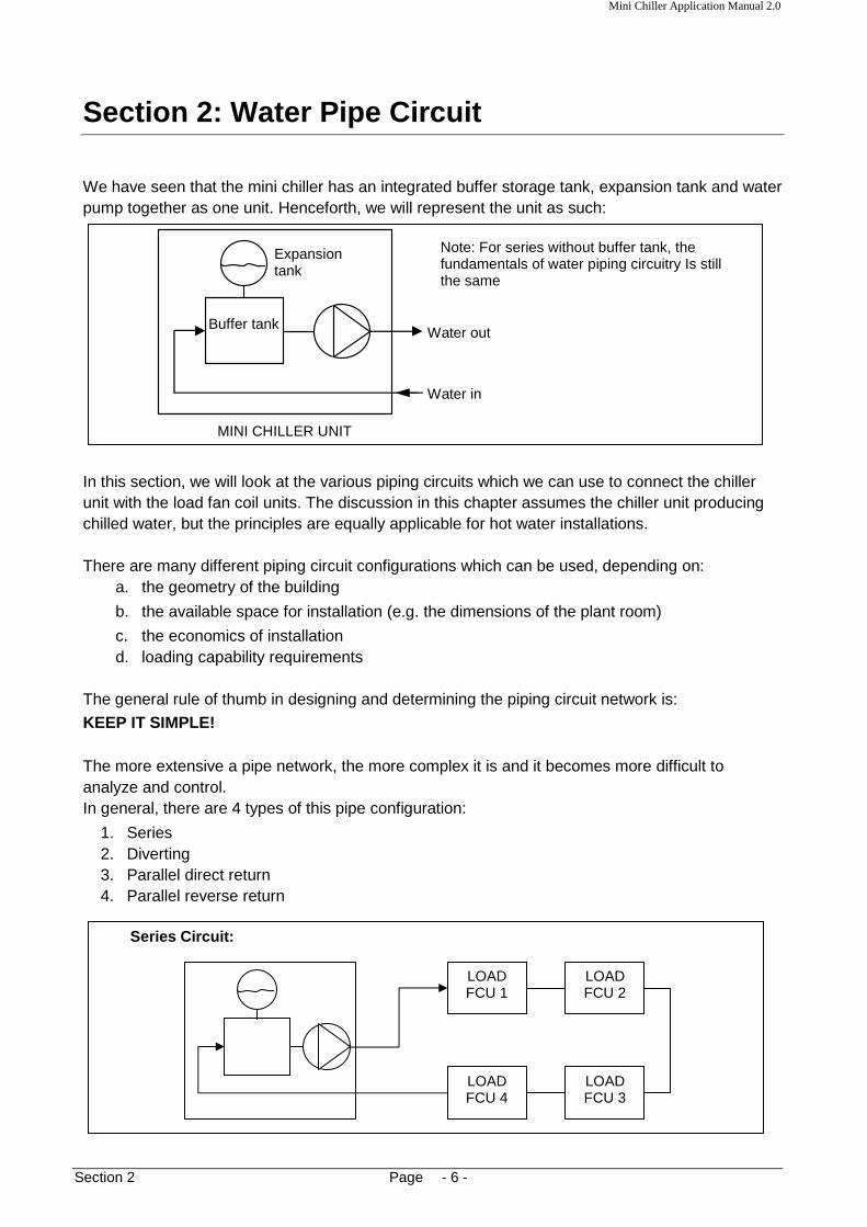
Section 2: Water Pipe Circuit We have seen that the mini chiller has an integrated buffer storage tank, expansion tank and water pump together as one unit. Henceforth, we will represent the unit as such:
In this section, we will look at the various piping circuits which we can use to connect the chiller unit with the load fan coil units. The discussion in this chapter assumes the chiller unit producing chilled water, but the principles are equally applicable for hot water installations.
There are many different piping circuit configurations which can be used, depending on:
a. the geometry of the building
b. the available space for installation (e.g. the dimensions of the plant room)
c. the economics of installation d. loading capability requirements
The general rule of thumb in designing and determining the piping circuit network is:
KEEP IT SIMPLE! The more extensive a pipe network, the more complex it is and it becomes more difficult to analyze and control. In general, there are 4 types of this pipe configuration:
1. Series 2. Diverting 3. Parallel direct return 4. Parallel reverse return
Mini Chiller Application Manual 2.0
Section 2 Page - 7 -
LOAD FCU 1
LOAD FCU 2
LOAD FCU 3
LOAD FCU 4
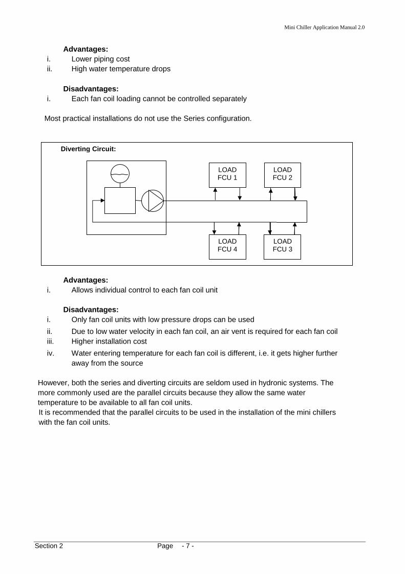
Diverting Circuit:
Advantages: i. Lower piping cost ii. High water temperature drops
Disadvantages:
i. Each fan coil loading cannot be controlled separately
Most practical installations do not use the Series configuration.
Advantages:
i. Allows individual control to each fan coil unit
Disadvantages: i. Only fan coil units with low pressure drops can be used
ii. Due to low water velocity in each fan coil, an air vent is required for each fan coil iii. Higher installation cost
iv. Water entering temperature for each fan coil is different, i.e. it gets higher further away from the source
However, both the series and diverting circuits are seldom used in hydronic systems. The more commonly used are the parallel circuits because they allow the same water temperature to be available to all fan coil units. It is recommended that the parallel circuits to be used in the installation of the mini chillers with the fan coil units.
Mini Chiller Application Manual 2.0
Section 2 Page - 8 -
Vertical installation
Fan coil units
Horizontal installation
Fan coil units
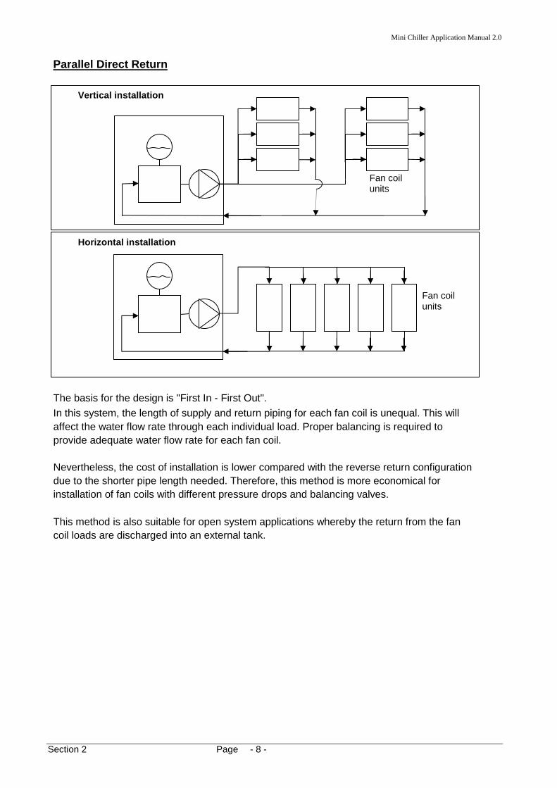
Parallel Direct Return
The basis for the design is "First In - First Out".
In this system, the length of supply and return piping for each fan coil is unequal. This will affect the water flow rate through each individual load. Proper balancing is required to provide adequate water flow rate for each fan coil. Nevertheless, the cost of installation is lower compared with the reverse return configuration due to the shorter pipe length needed. Therefore, this method is more economical for installation of fan coils with different pressure drops and balancing valves. This method is also suitable for open system applications whereby the return from the fan coil loads are discharged into an external tank.

Mini Chiller Application Manual 2.0
Section 2 Page - 9 -
Fan coil units
Horizontal installation
Vertical installation
Fan coil units
Parallel Reverse Return
The basis for the design is "First In - Last Out". In this installation, the supply and return water pipes are of nearly equal lengths. Thus, it seldom requires balancing of water flow rate for individual fan coil unit. If required, this balancing will be easier.
This method is recommended if all the fan coil units have the same or nearly the same pressure drops. Another advantage of this reverse return system is a reduction of the working pressure drop across any balancing valves used for the fan coil units. However, such a system is not recommended for high-rise buildings because of the vertical weight of the extra piping required. In such instances, it may be more practical to use direct return systems.
The extra piping also does not give any advantage in open system applications because the same atmospheric condition exists at all open points of the system.

Mini Chiller Application Manual 2.0
Section 2 Page - 10 -
Reverse return
Direct return
Return
Supply
Parallel Reverse Return Header, Direct Supply Rise This is a variation of both the direct and reverse return systems, whereby it is not feasible to have a full reverse return piping. Instead, only the return header is in reverse, whereas the supply to the individual fan coils is in direct configuration.
This method will have the advantage of lower installation cost with some benefits of a better water balanced system. Balancing valves are required for each fan coil unit for proper flow balancing.
Mini Chiller Application Manual 2.0
Section 2 Page - 11 -
External pump Chiller
Tank
Return from load
Supply to load
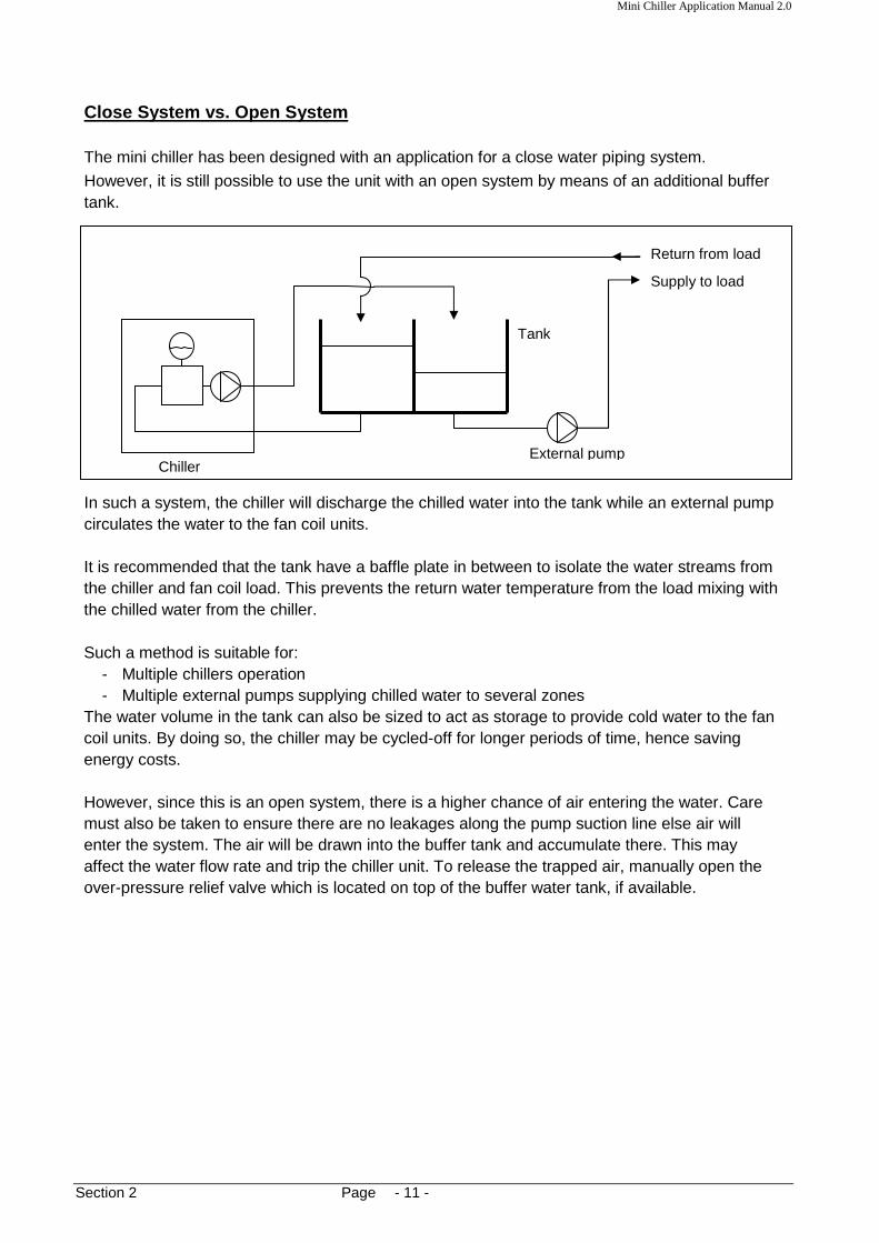
Close System vs. Open System The mini chiller has been designed with an application for a close water piping system.
However, it is still possible to use the unit with an open system by means of an additional buffer tank.
In such a system, the chiller will discharge the chilled water into the tank while an external pump circulates the water to the fan coil units. It is recommended that the tank have a baffle plate in between to isolate the water streams from the chiller and fan coil load. This prevents the return water temperature from the load mixing with the chilled water from the chiller. Such a method is suitable for:
- Multiple chillers operation - Multiple external pumps supplying chilled water to several zones
The water volume in the tank can also be sized to act as storage to provide cold water to the fan coil units. By doing so, the chiller may be cycled-off for longer periods of time, hence saving energy costs. However, since this is an open system, there is a higher chance of air entering the water. Care must also be taken to ensure there are no leakages along the pump suction line else air will enter the system. The air will be drawn into the buffer tank and accumulate there. This may affect the water flow rate and trip the chiller unit. To release the trapped air, manually open the over-pressure relief valve which is located on top of the buffer water tank, if available.
Mini Chiller Application Manual 2.0
Section 2 Page - 12 -
Secondary booster pump
Load
Bypass loop
Primary pump in chiller unit
A
B
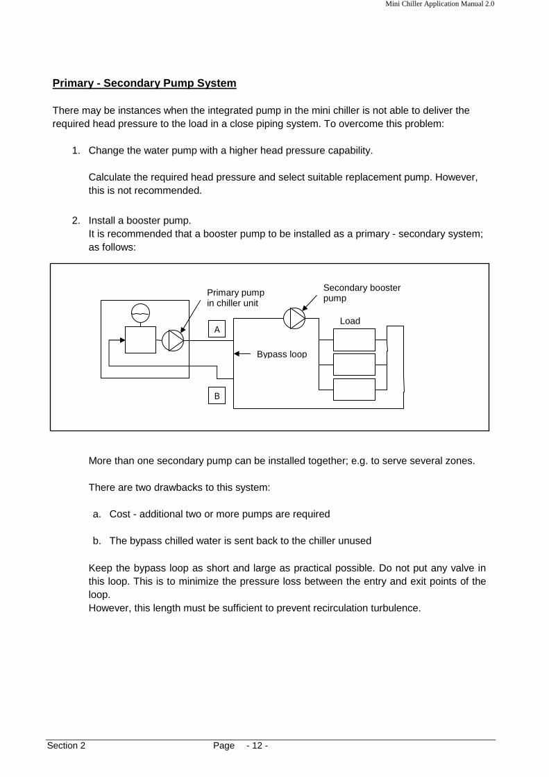
Primary - Secondary Pump System There may be instances when the integrated pump in the mini chiller is not able to deliver the required head pressure to the load in a close piping system. To overcome this problem:
1. Change the water pump with a higher head pressure capability.
Calculate the required head pressure and select suitable replacement pump. However, this is not recommended.
2. Install a booster pump. It is recommended that a booster pump to be installed as a primary - secondary system; as follows:
More than one secondary pump can be installed together; e.g. to serve several zones. There are two drawbacks to this system: a. Cost - additional two or more pumps are required b. The bypass chilled water is sent back to the chiller unused
Keep the bypass loop as short and large as practical possible. Do not put any valve in this loop. This is to minimize the pressure loss between the entry and exit points of the loop. However, this length must be sufficient to prevent recirculation turbulence.

Mini Chiller Application Manual 2.0
Section 2 Page - 13 -
External pump in series Primary pump
Load
The temperature of water entering the load will depend very much on the sizing of the secondary pump.
1. If the capacity of primary pump = secondary pump, there will be no flow in the bypass
loop. Hence, the water temperature entering the load will be equal to the water temperature leaving the chiller.
2. If the capacity of primary pump > secondary pump, there will be a net flow down the loop
and returned to the chiller unused. Therefore, tee A becomes a diverging tee and tee B becomes a mixing tee. The water temperature entering the load will also be equal to the water temperature leaving the chiller. However, the water temperature entering the chiller will be colder due to mixing of the unused chilled water at tee B.
3. If the capacity of primary pump < secondary pump, there will be a net flow up the loop
from B to A. Thus, tee A becomes a mixing tee and tee B becomes a diverging tee. Then, the water temperature entering the load will be in between the water temperature leaving the chiller and the water temperature entering the chiller.
There may be installations using pumps in series to boost the head pressure. But this is not recommended due to a high chance of wrong pump sizing which can cause damage to the pumps themselves.
For this to work properly, both pumps must be of the same capacity. Else, the greater capacity pump will overflow the lesser pump and cause:
a. Cavitation problems to the lesser pump.
b. Excessive pressure drops across the pump itself.
c. The extra head pressure build-up may cause damage to some of the components in the chiller itself.

Mini Chiller Application Manual 2.0
Section 2 Page - 14 -
CHILLER 1
CHILLER 2
CHILLER 3
Chilled water supply
Chilled water return
Return header
Supply header Check valve
Multiple Chiller Installation
In most cases, one single chiller will not be sufficient to provide the cooling load of a system. Several chillers must be combined together to give the required loading.
Generally, these chillers will be installed together in parallel. There are several ways to do this:
1) Common Supply and Return Headers
This method is most preferred and commonly used because of the lower cost and ease of installation.
Each chiller is normally set at different return water temperature to facilitate load staging. As the temperature becomes colder, the chillers will switch off one by one.
Generally, the header pipe size is larger than the supply and return pipes, e.g. one or two size larger. This is to have a low pressure drop along the header. Check valves are usually located along each chiller supply pipe to prevent back flush of water once the chiller is switched off. Such back flow may damage the water pump.
However, this method has several drawbacks:
a. Proper balancing of the water flow rate through each chiller is crucial.
b. If any one chiller is off, the water flow to the load will be affected. So much so that during low load conditions, when the return water temperature is cold, and all the chillers have cycled off, no water will be pumped to the load. To overcome this problem, it is necessary to ensure the pump runs continuously as long as one fan coil unit is in operation.

Mini Chiller Application Manual 2.0
Section 2 Page - 15 -
header
Water will experience a higher resistance to flow to common pipe from the furthest branches.
CHILLER 1
CHILLER 2
CHILLER 3
To load
Return from load
Secondary pumps
Bypass loop
c. Since all the water is pumped into one supply line, there is less flexibility in zoning the water distribution. The pump head may not be sufficient to deliver water to zones of high pressure losses, e.g. at the furthest end of the pipe system.
Because of the importance of water flow balancing among all the parallel chillers, the design of the header is very important. Place the common pipe near the center of the header pipe. This will help to balance the water distribution between the left and right sides of the header.
If the common pipe is at one end of the header, water from the branches at the other end of the header will find more difficulty to flow into the common pipe.
Balancing valves must be installed at each supply branch to ensure adequate water flow rate through each chiller unit.
2) Primary-Secondary System

Mini Chiller Application Manual 2.0
Section 2 Page - 16 -
[A] Bypass loop
To load
Return from load
Secondary pumps
[B]
Bypass loop
To load
Return from load
Secondary pumps
In this method, the load side of the system is isolated from the chiller side. Chillers of different capacities can be installed together without much balancing problems and effect on the supply flow rate to the loading. It just requires individual balancing of the flow rate through each chiller by using the balancing valves. Check valves and balancing valves are recommended to be installed for each chiller supply pipe.
The secondary pump alone will handle the flow and pressure requirements of the loads.
Because of this secondary pump, the sequencing of the chillers will not affect the water supply to the load when any of the primary pumps switches off. Several secondary pumps can also be installed to the bypass loop to serve several zones. This creates flexibility of installation.
The only drawback to this method is cost. The piping network is more extensive and additional water pumps are required.
It is important that the bypass loop is located correctly. The following two are questionable variations to the above method:

Mini Chiller Application Manual 2.0
Section 2 Page - 17 -
CHILLERS
Tank
Return from load
To load
This method is for an open system
For both method [A] and [B] above, the return water temperature for the multiple chillers will not be the same due to mixing. This will cause inefficiencies and energy wastages to the chiller operation.
3) Common Tank System
As seen from the diagram, each chiller and secondary pump forms its own individual pipe circuit. There is no cross flow among each of them. This has been achieved with the common tank which acts as a buffer storage tank.
Therefore, there is no need of check valves. Normal globe valves will suffice to ensure proper water flow through each chiller.
Usually, the tank is at a higher elevated position, to allow gravity feed of water to the chillers and pumps.
This method is most expansive to install due to the additional piping and tank required for the system.
Please refer to Page 14 for cautions during installation and operation.

Mini Chiller Application Manual 2.0
Section 2 Page - 18 -
To load
Return from load
This is not a common header pipe
To load
Return from load
Auxiliary tank
4) In some instances, variation to method (1) has been used whereby common headers are NOT installed to the multiple chillers. Instead, the chillers are connected together with one supply and return pipe only.
This method is still possible but there will be higher pressure drops along the common pipe lines. It is recommended that a larger pipe size to be used along this common line to reduce the friction losses. Water flow rate tends to be faster at the tee nearest to the main supply lines due to lower friction. Therefore, proper balancing to ensure sufficient distribution to each chiller is vital.
A First In - Last Out arrangement between the supply and return lines may be useful to reduce the problem of distribution.
5) Another variation to the primary-secondary system mentioned in (2) above, is to use an
auxiliary tank to replace the by-pass loop. By using this tank, we can ensure a minimal pressure drop between the entry tee and exit tee of the secondary circuit.

Mini Chiller Application Manual 2.0
Section 2 Page - 19 -
CHILLER 1
CIRCUIT 1
CIRCUIT 2
CIRCUIT 3
CHILLER 2
CHILLER 3
CIRCUIT 1
CIRCUIT 2
CIRCUIT 3
Multiple Chiller, Single Fan Coil Load With Multipl e Circuits There are instances where several chillers are used to supply the chilled water to a large single fan coil unit. Each chiller will serve one of the multiple circuits of the heat exchanger coil in the fan coil unit. There are two possible ways to install the pipe circuits for this system:
a. Individual Circuiting
b. Common Header

Mini Chiller Application Manual 2.0
Section 2 Page - 20 -
The first method has more extensive pipe works. But the water side flow control is easier and there is less pressure drop. Globe valves may be needed to ensure sufficient flow rate. Check valves are not required. Due to the header pipes in the second method, check valves are needed for each chiller. Globe valves or balancing valves are also needed for each chiller for water balancing. All the pumps will operate in parallel and a higher water pressure drop is expected. Furthermore, balancing valves are also required in each circuit of the fan coil unit for proper balancing of the entire coil. Nevertheless, if any one of the chiller is OFF, the second method will always allow an even water distribution to the whole heat exchanger in the fan coil unit. In the first method, hot air will by-pass through the portion of the coil which the chiller is OFF.

Mini Chiller Application Manual 2.0
Section 2 Page - 21 -
Make Up Water Supply The make up water supply is used to refill water back into the chiller system in the event of:
a. Leakage in the system b. Maintenance service
The supply is usually from the main domestic pipe and it is usually connected to the water return pipe of the pump; due to the lower pressure which will assist "sucking" in the water. However, should the pressure in the main supply pipe is lower than the pressure in the return pipe; water will not enter the system. In view of this, it is necessary to install a check valve along the make up supply pipe to prevent back flow out of the system.
Two methods of installing the make up supply pipe line are suggested: a) Direct supply from reservoir storage tank
b) Automatic pressure regulating valve
The regulator will only open when the inlet supply pressure is higher than the pressure in the return pipe line.
CHILLER
Storage tank
Return Check valve
Height of water level in tank must be sufficient to deliver the required head pressure into the chiller system.
CHILLER
Domestic water supply
Return
Check valve
Pressure regulator valve
R

Mini Chiller Application Manual 2.0
Section 3 Page - 22 -
Long Piping Installation One of the main advantages of using mini chillers is the ability to have long water piping installations. However, it is important to check that the water pump head pressure capability is adequate to pump the water through the pipe network. The longer the pipe length, the higher is the pressure drop. If the pump head is insufficient, it may be necessary to change the water pump itself. See Section 5. With such installations, it is also important to check the condition of the automatic air vent valve. A high pressure drop along such pipe network may result in the return water to have a negative pressure (i.e. suction vacuum pressure in the buffer tank). Due to the mechanism of the air vent, air will be drawn into the buffer tank itself! This in turn will cause the pump to be air-locked. A symptom of such condition is that air will always be purged out of the tank when we manually open the air vent. The solution to this problem is to remove the automatic air vent and plug up the hole. Make sure that all the air trapped is purged out of the system before plugging it. This can be done by continuously filling up the system with water until no air bubbles comes out of the hole.
Mini Chiller Application Manual 2.0
Section 3 Page - 23 -
Water inlet
Water outlet
Water outlet
Water inlet
Connection Ø 1” BSPT
Connection Ø 1-1/4” BSPT
Water outlet
Water inlet
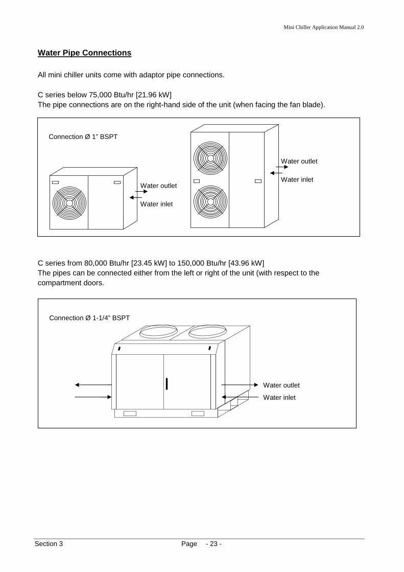
Water Pipe Connections All mini chiller units come with adaptor pipe connections. C series below 75,000 Btu/hr [21.96 kW] The pipe connections are on the right-hand side of the unit (when facing the fan blade).
C series from 80,000 Btu/hr [23.45 kW] to 150,000 Btu/hr [43.96 kW] The pipes can be connected either from the left or right of the unit (with respect to the compartment doors.

Mini Chiller Application Manual 2.0
Section 3 Page - 24 -
C Series 210,000 Btu/hr (61.49 kW) The pipes can be connected either from the left or right of the unit (with respect to the service panels.
Connection Ø 1-1/2” BSPT
Water outlet
Water inlet
Mini Chiller Application Manual 2.0
Section 3 Page - 25 -
Section 3: Water Pipe and Fittings There are several types of pipe we can use for the water piping:
1. Black carbon steel pipe 2. Copper pipe 3. PVC pipe
Do not use galvanized iron (GI) steel pipe! This is because the zinc coating on the GI pipe will have an electrolytic reaction with the copper components of the system, e.g. the brazed plate heat exchanger and fan coil unit heat exchanger. All external pipes carrying chilled or hot water should be insulated. See Section 7.
The zinc will be the sacrificial metal and deposit itself on the copper surfaces.
a. The pipe wall thickness will slowly eat away and cause leakages b. The zinc deposit on the copper surfaces will retard heat transfer process. It may also
reduce the gap between plates in the BPHE and slows the water flow rate. For a single run installation, the pipe length will depend very much on the method of installation and the fittings used. The more complex the piping network is and the more fittings there are, the higher will be the friction losses. This will limit the piping length available. For the recommended pipe length, refer to available head in Technical Manual of the respective mini chiller unit. Always calculate the friction losses in the system and compare this with the capability of the water pump in the chiller unit. See Section 4.
1. Black Steel Pipes
The black steel pipes are the most commonly used in chiller installations. It is relatively cheap and by far the strongest among the 3 types mentioned above. However, these pipes are heavier and require more extensive work to join and install.
The common pipe sizes are determined from the ASME (American Society of Mechanical Engineers) standard B36.1 OM which specifies the pipe dimensions. See Appendix 1.
Generally, steel pipes are sold in lengths of 6 meters each. The dimensions of importance which we need to know is the nominal pipe size (NIPS) and schedule number (wall thickness). For pipes 14" (350mm) and larger, the nominal diameter is the same as the actual outside diameter.
For pipes between 3" (80mm) to 12" (300mm), the nominal diameter is close to the actual inside diameter.
However, for pipes smaller than that, the nominal value does not correspond to any actual dimension.

Mini Chiller Application Manual 2.0
Section 3 Page - 26 -
Steel pipes are manufactured with different wall thickness. The ASME standard has defined schedule numbers to identify these specifications. A pipe with a nominal pipe size may have several schedule numbers. See also Appendix 1
Therefore, pipes may have the same nominal diameters (outside diameters) but with different inside diameters because of the different schedule numbers. The usual schedule numbers are 10, 20, 30, 40, 60, 80, 100, 120, 140 and 160 with the thickness increasing with the numbers. These numbers are further classified as Standard (ST), Extra Strong (XS) and Double Extra Strong (XXS) whereby applications requiring higher pressures will need pipes with thicker walls.
However, in the HVAC industry and for our mini chiller installation, a standard schedule 40 pipe will suffice.
The steel pipes may be joined by several methods:
1. Arc welding
2. Thread (usually up to 50mm) with PTFE Teflon white tape
3. Flange with gaskets
2. Copper Pipes
Copper pipes are chosen for water piping because of their resistance to corrosion and ease of installation. The pipes are light and ductile. However, the cost of these pipes is higher compared with steel pipes (generally by 3 -5 times).
The sizes of these copper pipes are defined by the ASTM (American Society for Testing and
Materials) standard B88 for water and drain services. See Appendix 2.
There is also another ASTM standard B280 which specifies the sizes of pipes used for refrigeration services with different wall thickness. This standard uses the outside diameter as the nominal size. These pipes are also generally sold in lengths of 6 meters.
Generally, the B88 standard defines 4 types of copper tubes: Type K, L, M and DMV with descending wall thickness. The most commonly used types are type L and M which have higher internal working pressures. These may be of hard drawn or soft annealed temper.
The copper pipes may be joined by:
1. Brazing
2. Soldering
3. Flare joint / compression joint fittings

Mini Chiller Application Manual 2.0
Section 3 Page - 27 -
3. PVC Pipes The plastic PVC (polyvinyl chloride) pipes are light, generally inexpensive and corrosion resistant. The pipes also have a very low friction factor (i.e. with smooth surface) which results in lower pumping power and smaller pipe sizes. However, these pipes are not suitable for high temperature applications as they losses strength rapidly at temperatures above ambient. The pipes also have high coefficient of expansion, i.e. at high temperatures any pipe joint made may become loose and leaks. Because of the weaker strength of the material, such pipes must be installed with shorter support spans.
As a result of the above mentioned disadvantages, it is not recommended for PVC pipes to be used for external applications, especially under direct exposure to sunshine. They may be suitable for indoor water piping, e.g. under ceiling spaces, attics, plant rooms, etc.
The PVC material is classified as a thermoplastic. Generally, there are two types:
1. U-PVC (unplasticized PVC): for general usage up to 60°C 2. C-PVC (chlorinated PVC): for higher temperature applications.
The PVC pipes and fittings used inside the mini chiller unit (factory assembled) are of DIN 8061/8062 standard. Therefore, use back pipes and fittings with the same standard when running pipes from the chiller to the fan coil units. It is recommended that pipes with pressure rating of PN16 (16 bar working pressure) to be used. See Appendix 3.
Do not use PVC pipes manufactured to other standard specifications, e.g. BS 3505/3506 as the fittings will not match with those used in the chiller. The pipe wall thicknesses are also different.
The usual method of joining the pipes and fittings is with solvent cementing / welding. Some fittings also have threads for joining purposes (with PTFE white tape).
It is recommended that 'IPS Weld-on PVC 717' solvent cement to be used. It is gray in colour and used for heavy-body applications.
The following are some guidelines to ensure that the solvent cement joint is done properly:
a. Cut the pipe square and deburr. Clean and dry surfaces before coating the cement. b. Apply a full, even layer of cement equal to the depth of the socket. Avoid excess and
puddling. c. Assemble while the cement is wet. If not wet, recoat parts. d. Ensure pipe fits snugly into socket. Give a twist of 1/8 to 1/4 turn. e. Hold for 30 seconds to prevent push out and allow for initial set. Wipe off excess. f. Allow curing time at least 5 minutes, up to 30 minutes. Longer curing time is better
for higher pressure/temperature applications.

Mini Chiller Application Manual 2.0
Section 3 Page - 28 -
Typical Pipe Fittings The following are typical pipe fittings used for installing the mini chillers. Note that the pipe fitting size of the chiller itself is as stated in Water Pipe Connections.
a. Steel Pipe
Because of the pipe fitting size, it is recommended that the connecting pipes and fittings to be joined with thread. However, where necessary, fittings for weld joining may also be used. The following standards are applicable for these fittings:
ASME B16.9, ASME B16.11, ASME B16.28 and ASME B1.20.1
• 90° elbow 45° elbow is also available but not commonly used, unless necessary.
• Tee joint
A tee joint can either be a flow mixing or flow diverging point, depending on the design of the pipe work.
• Reducer
Some reduces/ fittings do not have these ribs: used for better gripping when tightening with pipe wrench.
• Nipple with reducing end Nipples are usually used for joining different types of fittings, e.g. an elbow with a reducer.
• Connector Used for joining two lengths of pipes together.
Internal thread
Internal thread
Internal thread
Internal thread
Internal thread

Mini Chiller Application Manual 2.0
Section 3 Page - 29 -
• Union/ coupling
Made up of two halves, each screwed into a pipe end. Both are then joined with a locking nut in between.
• Flange
This method is not recommended for the small pipe size used for the mini chiller.
** The fittings for weld joining are very similar to those mentioned above, i.e. they do not come with the thread portion. They may be butt-welded or socket-welded.
BUTT SOCKET
Gasket to be placed on the mating surfaces of both flanges
Holes for bolt and nut
flange
connector nipple

Mini Chiller Application Manual 2.0
Section 3 Page - 30 -
b. Copper Pipe The most commonly used method of joining copper pipes is brazing with an oxy-acetylene flame and copper filler rods. For this purpose, one end of the pipe is expanded by using an expander tooling, and the end of the other pipe is inserted into the expanded end. The joint is then brazed together. [See Appendix 4 for expansion dimensions] Similarly, fittings are available for such brazing joints:
• 90° elbow
• reducer
• tee joint
• connectors Sometimes, copper connectors are used instead of expanding the copper ends. This is especially with larger pipes where expanding becomes more difficult because of the thicker wall thickness.
Also, an alternative to using elbows is to just bend the pipes with a pipe bender to suit the installation requirement. Various bending angles can be achieved with this method. However, the larger the pipe size, the more difficult this will become.
Expanded end
Usually, the pipe outer diameter will insert into the reducer inside diameter
Some may come with reducer end
Expanded end
Expanded end
Pipe bend
Expanded end

Mini Chiller Application Manual 2.0
Section 3 Page - 31 -
CAUTION! Do not bend the pipes with hands. This will cause the pipe to collapse at the bending portion. Use the suitable pipe bending tool. Manual hand bender allows a maximum size of 3/4". Pipes up to 1-3/8" can still be bended by using bending machine. NOTE: During brazing of copper-to-copper pipes, copper filler rods of 0% silver may be used. It is a good practice to pass nitrogen gas inside the copper pipes while brazing to prevent oxidation.
Copper Pipe: Compression Fittings For some installations, the piping are connected using compression fittings. These fittings enable easy installation and dismantling. However, the cost for these fittings is higher. They are also not as strong as brazing joints. Chances of leakage are higher. Generally, the fittings have mounting rings which are slipped onto the copper pipes. The ring is then pushed against the fitting internal surface and a locking nut is used to hold the assembly together.
• 90° elbow
• 90° elbow with threaded ends Such elbows are for special applications. For example, connection with steel pipe fittings, connection with a water tank
• tee joint
Locking nut
Mounting ring
Normal elbow
Female thread
Male thread
Ribs for gripping with wrench

Mini Chiller Application Manual 2.0
Section 3 Page - 32 -
• connector
Used for connecting two pipes together. Some have threaded ends for connection with other fittings.
• union Function is similar to the steel type. Used for connecting two pipe together with flexibility of easy connection and dismantling. Some have threaded ends, others with compression fitting ends. In some installations, the copper pipes are brazed (with silver flux) onto each half of the union and then connected together with the locking nut. NOTE: Brazing of copper to brass requires filler rods with 34% silver.
Female thread
The 2 halves opened up threaded end
Locking nut

Mini Chiller Application Manual 2.0
Section 3 Page - 33 -
c. PVC Pipe It is recommended that the PVC pipe fittings used to be in accordance to the DIN 8062 standards. These fittings have thicker walls and able to withstand higher pressures and temperatures. Generally, these fittings are the cheapest and easiest to install.
• 90° elbow With the threaded end, it is possible to connect with a steel pipe or steel fitting
• tee joints
• connector Used to connect two PVC Pipes together with solvent cement
• adaptor/sockets The sockets may have male or female threaded ends. Such sockets are useful to adapt connection with a steel pipe or tank.
Some elbows have threaded ends

Mini Chiller Application Manual 2.0
Section 3 Page - 34 -
• union Similar to the steel and copper versions, these unions enable easy connection and dismantling of two PVC pipe ends. The PVC pipes are joined to the two halves by using solvent cement and then they are assembled together with the locking nut.
• reducer
The 2 halves of the union
Locking nut

Mini Chiller Application Manual 2.0
Section 3 Page - 35 -
turbulence occurs here and causes high friction losses
Return water
The higher velocity of flow in the return “pulls” water out of the tee branch
Bypass branch
Backflow of water
Return water
Bypass branch
Do not allow the higher return water velocity to “ram” into the tee joint. This may cause a backflow into the bypass branch
Tee Joint Installation Care must be taken during installation of tee joints. Two cases are mentioned here to demonstrate the importance of understanding the design of the water flow system.
a. Avoid "bullheading"
Do not connect piping to the tee connection with opposing flow directions.
b. Encourage eduction out of a bypass tee branch.
Mini Chiller Application Manual 2.0
Section 3 Page - 36 -
Valves In Section 2, we have look at several piping network configurations. The diagrams shown in that section have been simplified. In actual situation, the piping will have most of the pipe fittings described earlier in this Section 3. In addition, valves are also installed along the piping lines.
Valves are used for the following purposes:
a. To isolate a component of the hydronic system from the rest of the system; thereby enabling easy maintenance and repair of that component.
b. To regulate the water flow rate through the system. c. To divert or mix flow directions, optimizing the water temperature in the system. d. To relieve or regulate pressure. e. To prevent backflow.
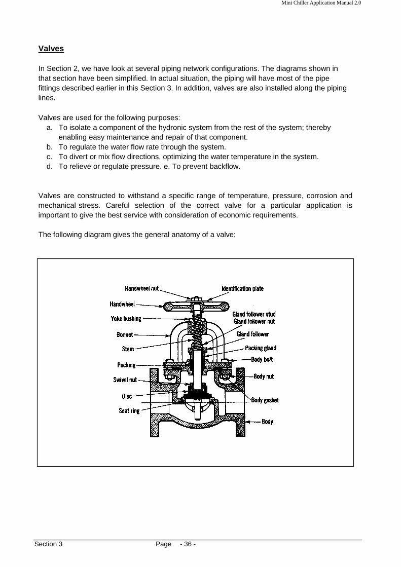
Valves are constructed to withstand a specific range of temperature, pressure, corrosion and mechanical stress. Careful selection of the correct valve for a particular application is important to give the best service with consideration of economic requirements.
The following diagram gives the general anatomy of a valve:

Mini Chiller Application Manual 2.0
Section 3 Page - 37 -
Generally, valves can be categorized as manual or automatic valves.
Manual Valves
The following are the types of manual valves commonly used in hydronic systems:
1. Globe Valve
Flow is controlled by a circular disc forced against or withdrawn from an annular ring, or seat that surrounds an opening through which flow occurs. The movement of the disc is parallel to the flow direction. - used for pipe diameters up to 300mm - used for throttling duty where positive shutoff is required
2. Gate Valve
Flow is controlled by means of a wedge disc fitting against seating faces. Gate movement is perpendicular to the flow direction. - has straight-through openings as large as the full bore of the pipe. - this type of valves are intended to be fully open or fully closed - should not be used to regulate or control flow - useful for isolation/shut-off purposes.

Mini Chiller Application Manual 2.0
Section 3 Page - 38 -
3. Ball Valve This valve has a precision ball seated between two circular seals or seats. A 90° turn of the handle will change the operation from fully open to fully close. - may be used for throttling duty - generally used with smaller pipe diameters (up to 75mm)
4. Butterfly Valve
This valve has a cylindrical body with an internal rotatable disc serving as the fluid flow regulating device. This disc's axis of rotation is the valve stem and it is perpendicular to the flow direction. A 90° turn will change the operation from fully open to fully close. - has low pressure drops - fast operation of valve - may be used for throttling duty

Mini Chiller Application Manual 2.0
Section 3 Page - 39 -
Setting hand wheel
Normally connected via tubing to a hand-held meter readout
Pressure tapping
5. Balancing Valve This type of valve provides throttling duty to regulate water flow rate for balancing purposes. Two ports are provided in the inlet and outlet ports of the valve to permit measurement of pressure drop across the valve. By using performance charts provided, the value of flow rate through the valve can be determined. The valve hand-wheel will have a setting scale to determine the amount of valve opening. This is useful during field commissioning and balancing. Generally, the internal construction is similar to a globe valve. It is more costly than the conventional throttling valves and it is only used in systems where proper and accurate balancing is required.

Mini Chiller Application Manual 2.0
Section 3 Page - 40 -
Automatic Valves This type of valves operates in conjunction with an automatic controller or device to control the fluid flow. These controllers are also called as actuators . There are several types of actuators commonly used:
a. Solenoid b. Electric motor c. Pneumatic
Such actuators will have gears, rack-and-pinion, cams and linkages to convert movement and allow opening and closing of the valve stem.
a. Solenoid Valve
This type of valve only allows either a totally open or close position. It has a magnetic coil which lifts or drops a plunger in the valve to open and close the flow of water. This occurs when the coil is either energized or de-energized. Such valves are generally used for pipe sizes up to 50mm only. They are suitable for small fan coil units which require water shut-off when the fan coil is switched off.
b. Electric Motorized Valve
The actuator has a built-in motor to produce a rotary motion. By using gears, cams or linkages, the valve stem will be opened or closed. Usually, the motor runs on DC power supply (24V). Generally, the actuator has positioning controls whereby the valve can stroke to any position between fully close to fully open. This is accomplished with a control signal from an external feedback controller. With this feature, it is possible to vary the water flow rate to suit any demand load of an application. Nevertheless, the cost of such valves is high.
Solenoid coil

Mini Chiller Application Manual 2.0
Section 3 Page - 41 -
c. Pneumatic Valve This type of valve has a flexible diaphragm clamped between an upper and lower housing. The valve stem is attached to the diaphragm. By injecting air pressure into the upper housing, the diaphragm will push the valve stem. An opposing spring force on the valve stem will also resist this movement. Therefore, by varying this air pressure, valve positioning can be achieved. For this to work, an external pneumatic converter/positioner must be used to regulate the air pressure. A thermostat may be used together for such a purpose. This cost for this type of valves is also high.
Position indicator
Motor drive
Valve (encased in insulation)
Upper housing
Lower housing
diaphragm Air pressure inlet
spring
Valve body

Mini Chiller Application Manual 2.0
Section 3 Page - 42 -
A A+B
B
A
A+B B
Two Way and Three Way Valves Automatic control valves used in hydronic systems may be classified as either two-way or three-way. All three types of actuators mentioned above may be used for these two types of valves. In the two-way valve , water flows into the inlet port and exits from the outlet port. By means of the actuator, the flow rate may vary from full flow to zero. There are two types available: single-seated and double-seated. For most applications, the single-seated type will suffice. In this type, there is only one valve seat and one plug-disc to close against the flow. However, for applications with higher operating pressures, the double-seated types may be used.
In the three-way valve , three ports are available. Depending on the application, these can be configured as a mixing or diverting valve.
1. Mixing Valve - two streams of water blends into a single stream
2. Diverting Valve -splits one stream into two different streams
Water in
Water out
Attachment to actuator
Attachment to actuator
1
2
3

Mini Chiller Application Manual 2.0
Section 3 Page - 43 -
supply
LOAD
return
2-way
supply return
LOAD
LOAD
mixing
diverting
3-way
Capacity Control With 2-Way and 3-Way Valves
The load of the fan coil unit can be calculated from the equation: Q = 4180 * (water flow rate, L/s) * (water temperature differential °C) Watt Therefore, the load is proportional to the water flow rate and ∆t. Both the 2-way and 3-way valve will vary the flow rate to accommodate changes in the load demand. With the 2-way valve, the system is considered as "variable flow, constant ∆t". With the 3-way valve, the system is considered as "constant flow, variable ∆t". It is recommended that the 3-way valve to be configured in ducted units as a mixing valve instead of a diverting valve. However, for the wall-mounted and ceiling mounted fan coil units, diverting valves are preferred. This is to prevent cold water from entering the fan coil unit when it is switched OFF. As a result, sweating on the heat exchanger, unit panels and the connecting joints will not occur when it is not running. It is also recommended that 2-way valves to be installed on the return pipe line of the fan coil unit.
Mini Chiller Application Manual 2.0
Section 3 Page - 44 -
Mini Chiller FAN COIL UNIT 1
FAN COIL UNIT 2
2 way solenoid
2 way solenoid
Pressure differential transmitter to monitor the amount of water used. If pressure goes higher than preset value, it will open the relief valve and bypass the water.
∆P LO
AD
LOA
D
LOA
D
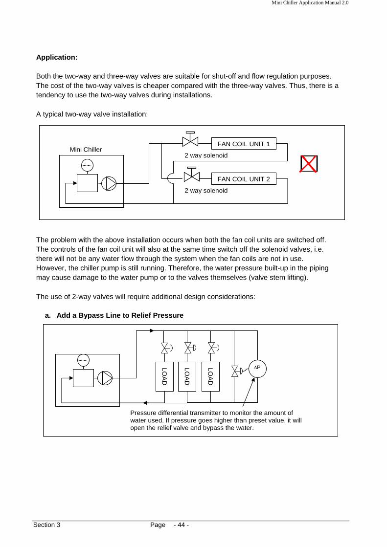
Application: Both the two-way and three-way valves are suitable for shut-off and flow regulation purposes. The cost of the two-way valves is cheaper compared with the three-way valves. Thus, there is a tendency to use the two-way valves during installations. A typical two-way valve installation:
The problem with the above installation occurs when both the fan coil units are switched off. The controls of the fan coil unit will also at the same time switch off the solenoid valves, i.e. there will not be any water flow through the system when the fan coils are not in use. However, the chiller pump is still running. Therefore, the water pressure built-up in the piping may cause damage to the water pump or to the valves themselves (valve stem lifting). The use of 2-way valves will require additional design considerations:
a. Add a Bypass Line to Relief Pressure

Mini Chiller Application Manual 2.0
Section 3 Page - 45 -
When the differential pressure becomes higher, the inverter will slow down the water pump to maintain the head pressure. If no demand, the water pump will stop running.
∆P
INV
LOA
D
LOA
D
LOA
D
Primary loop
b. Use a Variable Speed Drive for the Secondary Wat er Pump.
c. In view of the difficulties mentioned above, it is recommended that 3-way valves to be used in the mini chiller hydronic system.
Since the 3-way valve gives a constant flow system, there will not be any problem when there is no load demand since the water will bypass through the valve when it is in the fully closed position (with respect to the load).

Mini Chiller Application Manual 2.0
Section 3 Page - 46 -
LOA
D
LOA
D
LOA
D
However, this system has one main disadvantage. Since the supply water is by-passed around the load coil, energy is wasted. This will cause the chiller to cycle on-off more frequent as the return water temperature becomes lower.
Therefore, in terms of energy efficiency, applications with 2-way valves are better. A possible solution to this is to use a combination of 2-way and 3-way valves. For example, 70% of the fan coil units are installed with 3-way valves while 30% with 2-way valves.

Mini Chiller Application Manual 2.0
Section 3 Page - 47 -
Other Type of Valves and Fittings
a. Check Valve
This valve will only allow flow in one direction, i.e. to prevent back flow of water. We have seen an example of usage in Section 2 with multiple chillers installation. There are two basic designs of these check valves:
1. swing check valve - can be installed in horizontal or vertical piping 2. lift check valve - only for horizontal piping installation
b. Plug Cock/Plug Valve
This type of valve is also used for throttling duty. It is less expansive compared with the globe valve or balancing valve. The setting also cannot be tampered with as easily as the globe valve.
Swing check valve Lift check valve
Valve stem without hand wheel. Use a spanner or wrench to open and close valve.
Plug with orifice port. With a 90° turn, the port will operate from fully open to fully close.

Mini Chiller Application Manual 2.0
Section 3 Page - 48 -
Pressure gauge
Impulse tubing loop
Gauge cock (Ball valve)
Main pipe line
c. Pressure Gauge Cock
Generally, this valve is a ball valve. It is used to isolate pressure gauges installed along the water pipe lines. The gauge cock is only opened during pressure measurement. When not in use, the valve is closed to prevent prolonged pressurizing to the gauge, therefore preventing damage to the gauge itself. It is also closed when changing a new gauge.
d. Safety Relief Valve [Optional]
The valve will open when the pressure exceeds a set value to prevent over pressuring the system which may cause damage. Normally, this is used when the system is running hot water (mini chiller in heating mode/reverse cycle) in a closed piping. The hotter the water temperature, the higher is the pressure due to expansion. Such valves are also useful for protection against sudden pressure shocks, e.g. water hammering, and over pressuring from water fill system. If the system is with an open piping and external tank, this valve may be exempted. The setting of the valve should be at least 10% higher than the expected maximum operating pressure. It should be installed at the location where this pressure may be expected to occur, e.g. near any expansion tanks or pump discharge lines. Pipe the exhaust from the relief valve to an external drain.

Mini Chiller Application Manual 2.0
Section 3 Page - 49 -
Air vent
Air vent pipe
e. Air Vent Valve
It is always a good practice to install an air vent at the highest position on the supply pipe of the piping network to allow purging of any trapped air in the pipe system. Such air vents are also useful during commissioning and system start-ups to prevent problems of the pumping operation. Always install the valve in a vertical position on top of the pipe.
Under normal condition, water will enter inside the valve and lifts a floating body which will raise a mechanism to close a pin-shutter. Reduction of the water level as a result of accumulated air will cause the float to drop and opens the pin-shutter thus releasing the air automatically.
Float body
Pin-shutter opens
NORMAL CONDITION AIR VENTING CONDITION

Mini Chiller Application Manual 2.0
Section 3 Page - 50 -
Water out
Water in
Strainer MINI CHILLER
Allow sufficient space to remove filter
Strainer with filter in downward position pump
floor
This method is not recommended
Strainer
pump
floor
f. Strainer The strainer is an important element in the piping system to remove particles (e.g. sand) and dirt from the water. If not, these impurities will damage the pumping mechanism and clogged-up valves and fittings. The recommended mesh size of the strainer is 16-20. IMPORTANT!!! The mini chiller unit does not have a built-in strainer. Always install a strainer on the
Do not install strainer on the water outlet pipe as the water velocity is higher. Install the strainer with the filter element in a downward position. This is to facilitate easy flushing during periodic cleaning.

Mini Chiller Application Manual 2.0
Section 3 Page - 51 -
Strainer 3-way valve
FAN COIL UNIT
socket welded joint
threaded joint
Thermometer
threaded joint
tee joint
flow
There is also a practice to install a strainer on the inlet pipe to a fan coil unit. This is done to protect the control valve from clogging.
g. Thermometer
Glass thermometers are installed on the inlet and outlet pipes of either the chiller unit or fan coil units. This is to measure the water temperature differential to determine the capacity performance. Usually, these thermometers are installed together with the pressure gauges. Installation can be done with a socket welded onto the pipe or a tee joint connection.
Filter mesh 16-20 recommended
Water outlet Water inlet

Mini Chiller Application Manual 2.0
Section 3 Page - 52 -
Thermometers can be installed vertically, horizontally or even at an angle. During installation, it is important to ensure that the sensing bulb is in touch with the flowing stream of water. If the thermometer is installed too "high" up the connecting socket, the bulb will measure the temperature of stagnant water in the socket.

Mini Chiller Application Manual 2.0
Section 3 Page - 53 -
Valve Sizing In selecting the suitable valve to use for an application, the following items must be considered:
1. What is the fluid medium of usage. In chillers, the fluid is water. There are valves specially designed for other fluids e.g. steam and air, which are not suitable for water.
2. What is maximum operating pressure and temperature.
3. What is the valve duty required - is it for throttling, shut-off, balancing, mixing, etc.
4. What is the pipe size to be connected Do not oversize or undersize a valve to suit the pipe size. Size the valve according to the flow requirements. Use reducers where applicable.
5. What is the flow rate required through the valve
6. What is the flow characteristics required - linear, equal percentage (See following pages)
7. What is the piping connection method to the valve - threaded, flanged Most of the above mentioned information may be obtained from the valve catalogs provided by the valve manufacturers. In sizing the valve, the general accepted method is by means of the Cv (flow coefficient). Different valves will have different Cv values. Formula:
Q = Cv * (∆ p) Definition: The Cv rating of any valve is the amount of water, Q (GPM) at standard conditions (60°F, specific gravity = 1) which will pass through the valve with a pressure drop, ∆p of 1 psi with the valve in a full open position. By using conversion factors, we can have the flow coefficient K v in metric units:
1 Cv = 0.857 Kv Definition: The Kv rating of any valve is the amount of water (m3/hr) at standard conditions (20°C, specific gravity = 1) which will pass through the valve with a pressure drop of 1 kg/cm2 with the valve in a full open position. If the reference pressure is 1 bar, then:
1 Cv = 0.857 Kv

Mini Chiller Application Manual 2.0
Section 3 Page - 54 -
supply
return
FAN COIL UNIT A
B
3-way
Pressure drop = 6 feet
For a given flow rate, we can select a valve with suitable Cv to give an appropriate pressure drop. These data are available in graphs provided by the manufacturer. See Appendix 5. Selection of the valve must be done so as not to have too high a pressure drop, else the water pump head will be insufficient for the system. These values of valve pressure drop can also be used during pump sizing. See Section 5. For control valves (modulating, throttling duty, 2-way and 3-way), the pressure drop should be no less than half the total pressure drop in the branch. This will allow a stable control. Example:
Pressure losses along piping works from A to B = 4.6 feet Pressure drop across 2 gate valves + coil heat exchanger = 6 feet Therefore, the control 3-way valve should have a pressure drop of at least
= 4.6 + 6 =10.6 feet = 4.59 psi ** Conversion: 1 psi = 2.309 feet water
If the flow rate through the branch is 6 GPM, what valve Cv should be used? Referring to the graph in Appendix 5, the Cv should be approximately 2.7. Therefore, a 3-way diverting valve with Cv of 2.7 (at full opening) should be selected for the above application. As can be seen from the example above, the valve sizing was done with the design flow at full opening. Thus, at reduced flows, the valve will close and this will increase the pressure drop. This can be seen from the following graph which depicts the system curve and pump curve for a single fan coil load. See Section 5 for more details on pump curves.

Mini Chiller Application Manual 2.0
Section 3 Page - 55 -
Pressure drop of valve with zero flow
Increased pressure drop with reduced flow
Pressure drop of control valve at full opening
System curve w/o control valve
Pump curve
reduced flow design flow
Head Pressure
Another consideration in selecting the suitable valve is to determine the flow characteristic through the valve. Generally, there are three types:
1. Quick Opening The valve shows a quick increase of flow for a small increase of opening. But as it reaches the open position, the rate at which the flow increases per movement of the opening reduces.
2. Linear This valve produces equal rate of flow increase per equal rate of opening.
3. Equal Percentage This type of valve produces an exponential flow increase as the valve opens up. The term equal percentage means that for equal amount of valve opening, the flow increases by the same percentage.
SELECT THIS TYPE OF CHARACTERISTICS

Mini Chiller Application Manual 2.0
Section 3 Page - 56 -
Heat transfer rate, %
Valve opening Flow rate, %
Selection of valve with equal percentage flow characteristics will give the best performance as this will give a linear heat transfer rate with flow rate:
For automatic on-off valves (e.g. solenoid 2-way, 3-way), the selection is easier. Generally, use the same size as the pipe size, with a low pressure drop (e.g; 2 -5 psig: fully open). Using a smaller size (with pipe reducers and adaptors), for economic reasons, is possible, but check for excessive pressure losses which will reduce the pump performance.

Mini Chiller Application Manual 2.0
Section 3 Page - 57 -
P
Water supply
Water return
Make up water (from main supply of water tank)
CHILLER Mini chiller connector
T
P T
Guidelines for Valve and Fitting Installation:
a. Gate valves (shut-off) are installed in the entering and leaving piping to the chiller and fan coil unit. This is to permit servicing and replacement of the equipment without draining the system. A globe valve may be used to serve as one of the shut-off valve and in addition to balance the flow rate.
b. Valves and fittings using threaded or welded joints will require unions to permit easy
removal for servicing or replacement. Unions are usually located between each gate valve and the equipment. Unions are also place before and after the control valve, and in the branch of the 3-way valve. If flange joints are used, the need for unions is eliminated.
c. Locate the control valve in between the gate valve and the equipment to permit removal
of the control valve without draining the system.
d. Strainers, thermometers and pressure gauges are located between the gate valve and the equipment.
The following diagrams illustrate examples of piping layout:
• Typical Mini Chiller Piping Installation:

Mini Chiller Application Manual 2.0
Section 3 Page - 58 -
Water return
Water supply
FAN COIL UNIT
Gauge cock
T
T
supply riser
return riser
FAN COIL UNIT
3 way mixing valve
T
T
• Typical Fan Coil Unit Installation: a. Horizontal installation
b. Vertical installation

Mini Chiller Application Manual 2.0
Section 3 Page - 59 -
Water supply
Water return
CHILLER 1
CHILLER 2
CHILLER 3
Globe valve
Make up water
P T
P T
P T
P T
P T
P T
• Multiple Chiller Installation:
**Globe valve will be used to balance the flow rate through each chiller. **Additional gate valves may be installed along the main supply and return lines to isolate the entire chiller assembly.

Mini Chiller Application Manual 2.0
Section 3 Page - 60 -
3 way diverting valve
air vent T
T
FAN COIL UNIT
3
FAN COIL UNIT
2
FAN COIL UNIT
1
T
T
T
T
T
T
globe valve
• Multiple Fan Coil Unit Installation:
**All three fan coil units to serve one area with a common thermostat. When temperature has reached set point, thermostat will send signal to 3-way valve to divert water away.

Mini Chiller Application Manual 2.0
Section 3 Page - 61 -
P
return
T
P T
CHILLER
globe valve
Secondary pump
adaptor (c/w rubber gasket)
P
supply
T
P T
CHILLER
return
To external pump
TANK
• Primary-Secondary System:
• Water Tank Installation (Open System):

Mini Chiller Application Manual 2.0
Section 4 Page - 62 -
Section 4: Pipe and Fitting Sizing In the previous section, we have looked at the different types of pipes which can be used in a
hydronic system. We have also looked at the various types of fittings used in conjunction with the piping. In this section, we will examine the friction losses which occur when water flows through the pipes and fittings. Friction losses are dependent on the following factors:
a. Water velocity b. Pipe internal diameter c. Pipe length d. Pipe internal wall roughness
Generally, friction increases when:
- Water velocity increases - Internal diameter decreases - Pipe length increases - Wall roughness increases
The basic formula to calculate pipe friction losses (Hf) is the Darcy-Weisbach formula:
Hf = f * (L/D) * v2/2g where f = friction factor L = pipe length D = pipe internal diameter v = mean velocity g = acceleration due to gravity
The friction factor is a function of the roughness parameter, e, which in turn depends on the pipe material (e.g. steel, copper, PVC), and the Reynolds number, Re.
Re = D * v ρ / * µ where ρ = density µ = dynamic viscosity
Generally, the friction losses are presented in graphical form, for various pipe material. See attached charts for steel pipe Schedule 40, copper pipe and PVC. Note that Carrier has developed two different types of graph for steel pipes, i.e. for close and open system. The friction losses for the open system are higher than the close system, for the same parameters. This is to take into account the vulnerability of open systems to cause pipe fouling and scaling on the internal surfaces. A factor of approximately 1.75 is used for this purpose. It is to be noted that the pipe friction loss charts presented are all for flows in the turbulent regime (Re > 10 000).
Mini Chiller Application Manual 2.0
Section 4 Page - 63 -
Water Flow Limitations The factors which determine the water velocity limits are noise, erosion and installation cost. If the piping is too small, noise and erosion levels will become unfavorable even though the cost is more economical. Conversely, choosing a larger pipe will incur higher costs. It is recommended that the following guidelines to be used for the mini chiller units:
1. The pipe friction loss used for the design of the system should be within 1 to 4 ft per 100ft of equivalent pipe length.
2. The velocity in the pipe should be less than 4 fps in view of the allowable noise
level generated for residential and commercial buildings. However, the noise is not caused by the water itself, but rather by free air, sharp pressure drops, turbulence, cavitation and flashing. If precautions are taken to eliminate air and turbulences, higher velocities up to 8 fps are acceptable.
3. The minimum velocity in the pipe should be 1.5 - 2 fps to allow air entrained in the water
to be carried to separation units (e.g. expansion tanks, locations of lowest pressure) for venting.
Taking into consideration (2) and (3) above, it is recommended that the water velocity in the pipe to be 2 - 8 fps. With this, the expected service life of the pipes is more than 8000 hours/year.
Conversion factors: 1 fps = 0.305 m/s 1 ft water = 248.84 Pa 1 ft = 0.305 m
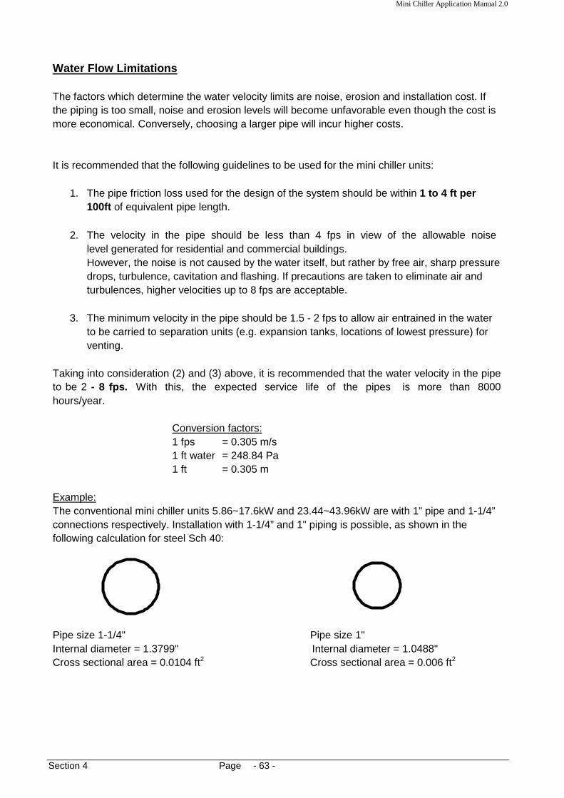
Example: The conventional mini chiller units 5.86~17.6kW and 23.44~43.96kW are with 1” pipe and 1-1/4” connections respectively. Installation with 1-1/4” and 1" piping is possible, as shown in the following calculation for steel Sch 40: Pipe size 1-1/4" Pipe size 1" Internal diameter = 1.3799" Internal diameter = 1.0488" Cross sectional area = 0.0104 ft2 Cross sectional area = 0.006 ft2

Mini Chiller Application Manual 2.0
Section 4 Page - 64 -
The following data are extracted from the mini chiller technical manual:
Model Water flow rate Velocity, fps
USGPM ft3/min 1-1/4” 1”
AC020C/CR 4.9 0.65 1.04 1.81
AC025C/CR 5.5 0.74 1.19 2.06
AC030C/CR 7.0 0.94 1.51 2.61
AC040C/CR 9.6 1.28 2.05 3.56
AC050C/CR 11.5 1.54 2.47 4.28
AC060C/CR 13.1 1.75 2.80 4.86
AC080C/CR 20.0 2.67 4.76 7.42
AC100C/CR 21.8 2.91 4.66 8.08
AC120C/CR 26.2 3.50 5.61 9.72
AC150C/CR 32.1 4.30 6.89 11.94
5AC030CR 7.2 0.97 1.55 2.69
5AC040CR 10.0 1.34 2.15 3.72
5AC050CR 11.3 1.51 2.42 4.19
5AC055CR 13.3 1.78 2.85 4.94
5ACV030CR 6.0 0.80 1.28 2.22
5ACV055CR 11.1 1.48 2.37 4.11
5ACV075CR 15.0 2.00 3.21 5.56
5ACV100CR 21.1 2.82 4.52 7.83
5ACV135CR 29.2 3.90 6.25 10.8
Model Water flow rate Velocity, fps
USGPM ft3/min 1-1/2” 1-1/4”
5ACV210CR 45.3 6.06 7.15 9.71

Mini Chiller Application Manual 2.0
Section 4 Page - 65 -
Equivalent Pipe Length The concept of equivalent pipe length is very useful in calculating friction losses along the hydronic pipe system. Definition:
The equivalent pipe length of a component in the pipe system is the length of a straight pipe which will give the same friction losses as the component itself. For example, we have a 1" elbow which gives a pressure drop of ∆P when a flow rate of Q passes through it. If a straight 1" pipe of length y feet gives the same pressure drop when a flow rate of Q flows through it, then, the equivalent pipe length of that elbow is y feet It is just like thinking that the elbow has been "replaced" with the length of straight pipe
Naturally, a straight pipe in the hydronic system does not require such usage of equivalent length. Therefore, the total equivalent pipe length of a hydronic system = straight pipe length + equivalent pipe length of all fittings and valves along the pipe Generally, equivalent pipe lengths of common valves and fittings are available. See attached tables (Appendix 7). An alternative method was published in the "ASHRAE Handbook: Fundamentals" for calculating the equivalent pipe length of tee joints. A graph is used to determine the number of equivalent elbows for the various flow conditions through the tee. This is then multiplied with the equivalent pipe length/pressure loss for the same size elbow. See Appendix 7. It must be noted that the equivalent lengths given in the attached tables for the fittings are only estimates. The values are more meaningful when used for steel pipes. Friction losses of copper and PVC fittings (e.g. elbows, tees, reducers) are quite similar to the equivalent steel type. Therefore, for estimation purposes, it is sufficient that the same equivalent lengths to be used for both copper and PVC pipes. Nevertheless, friction loss values for different pipe material will be used in the computation of the total friction in the piping system. If specific friction losses for any fitting are available from the manufacturer, it is advisable to use these values instead of the estimates given in the tables. This is especially applicable to valves (specific Cv) and strainers (different mesh sizes).

Mini Chiller Application Manual 2.0
Section 4 Page - 66 -
Internal and External Friction Losses The friction losses of the straight pipes and fittings are considered external losses to the hydronic system. Other than that, there are also losses in the chiller unit itself, i.e. through the brazed plate heat exchanger (BPHE), internal pipework, pump fittings, flow switch, etc. All these internal losses are as tabulated below:
Model Friction loss Nominal water
psi Flow rate, GPM
AC020C/CR 4.4 4.9
AC025C/CR 3.1 5.5
AC030C/CR 3.2 7.0
AC040C/CR 5.7 9.6
AC050C/CR 6.1 11.5
AC060C/CR 5.4 13.1
AC080C/CR 9.1 20.0
AC100C/CR 8.5 21.8
AC120C/CR 8.7 26.2
AC150C/CR 10.6 32.1
5AC030CR 3.4 7.2
5AC040CR 6.2 10.0
5AC050CR 5.9 11.3
5AC055CR 5.6 13.3
5ACV030CR 4.2 6.0
5ACV055CR 4.5 11.1
5ACV075CR 9.0 15.0
5ACV100CR 9.2 21.1
5ACV135CR 12.2 29.2
5ACV210CR 3.44 45.3 In the same manner, each fan coil unit has its own internal losses through the heat exchanger. Please refer to the respective Technical Manual for the values of these losses.

Mini Chiller Application Manual 2.0
Section 5 Page - 67 -
Friction Loss Calculation It is of utmost importance that a calculation to be made to determine the total friction loss along the piping network. This is to ensure that the internal water pump is able to deliver the required flow rate through the system. If the friction loss is too high, the flow rate will reduce, thereby causing improper operation of the chiller. If the friction loss is too low, the piping system may be redesigned for cost savings and better efficiency. The following guidelines should be followed during calculation:
1. It is necessary to have a drawing of the entire piping network, showing the lengths, sizes, material and fittings used. Such drawing may be in 2-dimensional or 3- dimensional (preferred). If the system is an open type, determine the height difference between the chiller unit and storage tank (if any). The straight length of a pipe is measured from center-to-center of each fitting along the pipe.
2. It is a good practice to have markings on the drawing for each branch of the pipe network. This will help in identification of which branch is being calculated.
3. The following information must be available for calculation: water flow rate (GPM) of each
pipe branch, internal friction losses of the chiller unit / fan coil unit and system available head. This information can be obtained from the product catalogs or technical manuals.
4. Calculate for the branch which gives the highest friction loss. This usually corresponds to the branch which has the furthest fan coil unit from the chiller.
5. It would be better to have the actual pressure drop across any of the fittings
used vs. the estimated equivalent lengths presented in the attached tables. This is especially so for the valves (with specific Cv values) and strainers (with different mesh sizes).
6. Add a safety factor of 15 - 20% to the final friction loss to account for estimation
errors and actual site installation of the piping system.
7. Check the final friction loss against the system available head. The system available head must be higher than this calculated value if the system is to work properly.

Mini Chiller Application Manual 2.0
Section 5 Page - 68 -
Section 5: Water Pump We have seen in Introduction that the pump is one of the fundamental components in a hydronic system. It circulates the water through all the other components in the system. We have also seen that in the mini-chiller unit, this pump is incorporated together with the other components as one package. In order to operate the chiller properly, it is vital to have an understanding of the pump characteristics and the factors which affect its performance. The water pump used in the mini-chiller unit is of the end-suction centrifugal type. Water enters through an inlet port at the center of an impeller and is pushed out by centrifugal forces of the impeller to a discharge volute around the impeller. As a result, a water pressure head is developed at the discharge port. To rotate the impeller, the pump assembly is coupled with an induction motor. Therefore, torque developed by the electric motor serves as the input power to the pump and gets converted as output in the form of the water head pressure. Factors which describes the performance of a pump:
a. Volumetric Flow rate b. Head Pressure c. Input Power d. Efficiency e. NPSH (Net positive suction head)
Various pump designs are available to meet different requirements. Some of the common parameters which pump manufacturers use for their design are:
1. Impeller Diameter Generally, the larger impeller will give higher flow rate and higher head pressure.
2. Number of Impellers
These multiple stages will increase the flow rate and head pressure as compared to a single stage impeller.
3. Impeller Speed
Most pumps are of the single speed design. However, variable speed pumps are also available which requires the usage of a speed controller (e.g. inverter unit). Generally, the faster the impeller rotational speed, the higher the flow rate and head pressure.
4. Material of Impeller and Pump Body
This will depend on the usage of the pump. Stainless steel and cast iron are two common materials used for the impeller and body. Applications which requires clean and hygienic pumping medium will require usage of stainless steel, e.g. for domestic water supply and food industries. Cast iron is sufficient for sewerage systems.
5. Pump Configuration/Type
There are various other types of pumps to suit the pumping needs, e.g. in-line centrifugal pumps, submersible pumps, dosing pumps, etc.

Mini Chiller Application Manual 2.0
Section 5 Page - 69 -
Proper selection of the pump is crucial to meet the pumping requirements. Other factors like the operating temperature and pressure of the medium must also be considered in the selection. Refer to the corresponding pump specifications and catalogs for detailed information of the pumps. Multistage end-suction pumps are used in the mini-chillers. The impeller and all movable parts in contact with the water are made of stainless steel. The pump suction and discharge chambers are made of cast iron. Please refer to the attached Technical Product Information for more detailed information of the pumps. (Appendix 8)

Mini Chiller Application Manual 2.0
Section 5 Page - 70 -
With increasing RPM speed of impeller
Q
P
With increasing impeller diameter
Q
P
Pump Performance One of the most useful performance charts of a pump is the P-Q curve, which describes the relationship between the head pressure (P) vs. the volumetric flow rate (Q). The shape of the curve is as follows:
This curve shows that when the head pressure increases, the flow rate reduces (and vice- versa). By calculating the system pressure drop, we can thus determine the flow rate when the pump is running. Hence, we can check whether the system pipe design is suitable for a particular pump application. This pump head pressure can also be measured at the pump discharge port by using a pressure gauge. The above curve is for a single fixed speed pump. If the pump were to operate under different power supply frequencies (e.g. from 50 Hz to 60 Hz), another set of curves must be used. For variable speed pumps, the P-Q curves will look as follows:
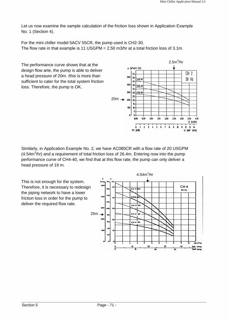
Mini Chiller Application Manual 2.0
Section 5 Page - 71 -
4.54m3/hr
25m
Let us now examine the sample calculation of the friction loss shown in Application Example No. 1 (Section 4). For the mini chiller model 5ACV 55CR, the pump used is CH2-30. The flow rate in that example is 11 USGPM = 2.50 m3/hr at a total friction loss of 3.1m. The performance curve shows that at the design flow arte, the pump is able to deliver a head pressure of 20m. /this is more than sufficient to cater for the total system friction loss. Therefore, the pump is OK. Similarly, in Application Example No. 2, we have AC080CR with a flow rate of 20 USGPM (4.54m3/hr) and a requirement of total friction loss of 26.4m. Entering now into the pump performance curve of CH4-40, we find that at this flow rate, the pump can only deliver a head pressure of 19 m. This is not enough for the system. Therefore, it is necessary to redesign the piping network to have a lower friction loss in order for the pump to deliver the required flow rate.
2.5m3/hr
20m

Mini Chiller Application Manual 2.0
Section 5 Page - 72 -
pump curve
Q
P
system curve
operating point
pump curve
Q
P
system curve 1
calculated operating point which doesn’t lie on the pump curve
system curve 2
2.5
20
∆P
System Curve The system curve of a hydronic system is a plot of the pressure loss vs. the flow rate of the piping system itself. This curve describes the performance of the piping network itself. By plotting this curve onto the pump P-Q curve, we have the following:
Note that the characteristic of the system curve is the opposite of the pump curve, whereby water will have a higher pressure loss in the piping system when the flow rate is higher. The intersection of these two lines will give the operating point of the system. What we have done in the Application Example No. 1 and 2 is to calculate the desired design operating point of the mini chiller with that particular piping network. In the first example, we have found that the pump has a much higher capacity compared with the requirement (System Curve 1)
In order to "balance" back the pump operation, we need to increase the piping friction loss by ∆P (e.g. by adjusting the globe valve) so as to obtain System Curve 2. If this is not done, the pump will deliver a much higher flow rate compared with the design value.

Mini Chiller Application Manual 2.0
Section 5 Page - 73 -
calculated operating point which lies above the pump curve
pump curve
Q
P
system curve 2
system curve 1
25
26
∆P
To load with a design flow rate q, and total pressure loss, p
P1 Water pressure measurement
MINI CHILLER
actual opening point
Q
P
design point
q
Measurement P1
p
In the second example, we find that the water pump is insufficient to cater for the system curve.
In order to use the mini chiller, it is necessary for the piping network to have a characteristic of System Curve 2. The only way to do so is to redesign the piping system to give a lower friction loss. Alternatively, we can use the pump P-Q curve during commissioning of the hydronic system. To do so, we need to measure the water pressure at the discharge port. This value is quite close to the actual head pressure developed by the pump. By plotting this pressure on the P-Q curve, we can then determine the approximate flow rate flowing through the system and compare it with the design requirement. Appropriate action can then be taken to ensure sufficient and correct amount of flow rate.

Mini Chiller Application Manual 2.0
Section 5 Page - 74 -
combined pump curve
Flow rate
Head pressure
single pump curve
2ϖ
P
ϖ
Parallel and Series Pump Operation We have seen examples of the mini-chillers operating in parallel, e.g. where they are connected together via a common supply and return header pipe. Such installations are common when the single chiller do not have sufficient cooling capacity. In the parallel operation, the water pumps will work together to deliver a higher water flow rate (which is equivalent to the summation of each individual pump flow rate) at the operating head pressure. Example: Two mini-chillers of the same model are connected together to a load as shown schematically (simplified) below:
The pump in each chiller is delivering a flow of ϖ GPM. Assume that the friction loss in each branch of the header pipe is the same. Therefore, the flow in the load will be 2ϖ GPM. If the total pipe friction loss is P ft, we can have the following pump curves:
Now, if the friction loss in each branch is different, this will cause the flow rate in each branch to be different, say ϖ1 and ϖ2. Therefore, the total flow to the load will become ϖ1 + ϖ2.
C1
C2
Load
header

Mini Chiller Application Manual 2.0
Section 5 Page - 75 -
combined pump curve
Flow rate
Head pressure
single pump curve
ϖ1 +ϖ2
P3
ϖ2
P1
P2
ϖ1
combined pump curve
Head pressure pump curve C1
ϖ1 +ϖ2
P3
ϖ2
P1
P2
ϖ1
X pump curve C2
Thus, the pump curves will become:
The two pumps will experience different head pressures P1 and P2. Therefore, the pressure after the header will be P3 when the two flows combine together. What happens when the two chillers C1 and C2 are of different model, i.e.; pumps of different characteristics? In such instances, we will still add the two curves together, and we will have the pump curves as follows:
Of course, both the pumps will be operating under different head pressures P1 and P2, and then combines together to give a pressure of P3 at the header.
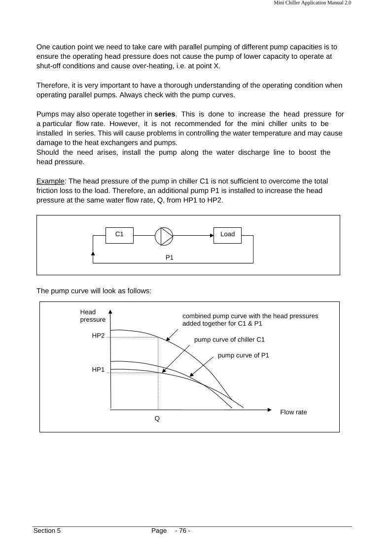
Mini Chiller Application Manual 2.0
Section 5 Page - 76 -
combined pump curve with the head pressures added together for C1 & P1
Flow rate
Head pressure
pump curve of chiller C1
HP1
Q
HP2
pump curve of P1
One caution point we need to take care with parallel pumping of different pump capacities is to ensure the operating head pressure does not cause the pump of lower capacity to operate at shut-off conditions and cause over-heating, i.e. at point X. Therefore, it is very important to have a thorough understanding of the operating condition when operating parallel pumps. Always check with the pump curves. Pumps may also operate together in series . This is done to increase the head pressure for a particular flow rate. However, it is not recommended for the mini chiller units to be installed in series. This will cause problems in controlling the water temperature and may cause damage to the heat exchangers and pumps. Should the need arises, install the pump along the water discharge line to boost the head pressure. Example: The head pressure of the pump in chiller C1 is not sufficient to overcome the total friction loss to the load. Therefore, an additional pump P1 is installed to increase the head pressure at the same water flow rate, Q, from HP1 to HP2.
The pump curve will look as follows:
C1 Load
P1

Mini Chiller Application Manual 2.0
Section 5 Page - 77 -
Cavitation The phenomenon of cavitation occurs when the absolute pressure at the pump suction approaches the vapour pressure of water at the operating temperature. If the suction pressure becomes lower than the vapour pressure, vapour pockets (in the form of bubbles) will form along the pump impeller blade passages. This means that there is a change of phase from liquid to gas. When these bubbles moves to the pressure side of the impeller, they collapse and implode on the blade surfaces. Such implosion causes erosion on the surface and creates a pressure wave (or hammering noise) which can cause a noisy operation. Such phenomenon is more critical with hot water because at higher temperatures, the vapour pressure increases and the tendency of achieving this pressure is easier. Therefore, it is important that a calculation of the pump inlet suction pressure to be made of the designed system and check it with the pump performance limits. The amount of this suction head pressure in excess of the vapour pressure required to prevent formation of the vapour bubbles is known as the Net Positive Suction Head Required (NPSHR). This NPSHR is a characteristic of a pump and is available from the manufacturer pump curves. Note: The NPSHR can also be defined as the frictional resistance from the pump inlet to the first impeller. In order to prevent cavitation, the actual system net positive suction head must be equal to or greater than the NPSHR value. This actual head pressure is also called as the Net Positive Suction Head Available (NPSHA).
NPSHR ≤ NPSHA How can we calculate NPSHA? There are two ways to do this:
1. For open systems, use the following equation: NPSHA = Pa + Ps - Pvp - Pf
where; Pa is the atmospheric pressure Ps is the static head of water level above the pump impeller Pvp is the vapour pressure of water at the operating temperature Pf is the friction loss of the suction pipe, fittings and valves. Generally, if the water tank is elevated compared with the mini-chiller unit, there will be no problem with cavitation, unless the friction loss along the suction line is very high. See following example.
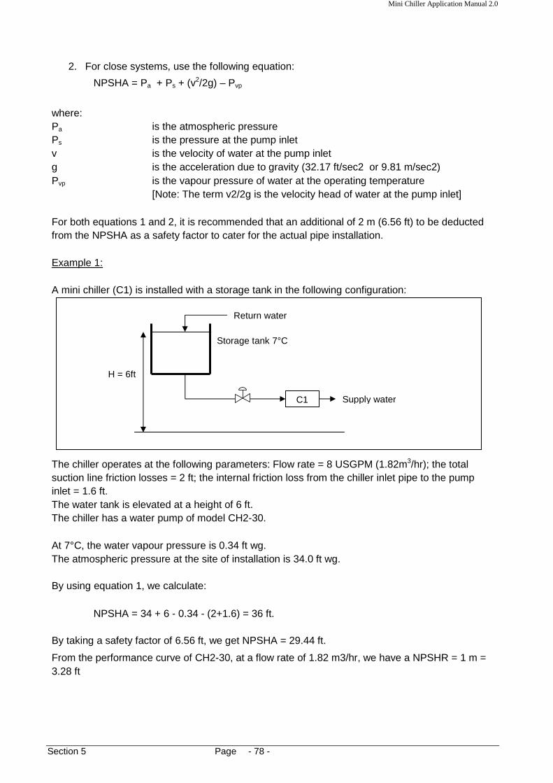
Mini Chiller Application Manual 2.0
Section 5 Page - 78 -
C1
Return water
Storage tank 7°C
Supply water
H = 6ft
2. For close systems, use the following equation:
NPSHA = Pa + Ps + (v2/2g) – Pvp
where: Pa is the atmospheric pressure Ps is the pressure at the pump inlet v is the velocity of water at the pump inlet g is the acceleration due to gravity (32.17 ft/sec2 or 9.81 m/sec2) Pvp is the vapour pressure of water at the operating temperature
[Note: The term v2/2g is the velocity head of water at the pump inlet] For both equations 1 and 2, it is recommended that an additional of 2 m (6.56 ft) to be deducted from the NPSHA as a safety factor to cater for the actual pipe installation. Example 1: A mini chiller (C1) is installed with a storage tank in the following configuration:
The chiller operates at the following parameters: Flow rate = 8 USGPM (1.82m3/hr); the total suction line friction losses = 2 ft; the internal friction loss from the chiller inlet pipe to the pump inlet = 1.6 ft. The water tank is elevated at a height of 6 ft. The chiller has a water pump of model CH2-30. At 7°C, the water vapour pressure is 0.34 ft wg. The atmospheric pressure at the site of installation is 34.0 ft wg. By using equation 1, we calculate:
NPSHA = 34 + 6 - 0.34 - (2+1.6) = 36 ft. By taking a safety factor of 6.56 ft, we get NPSHA = 29.44 ft.
From the performance curve of CH2-30, at a flow rate of 1.82 m3/hr, we have a NPSHR = 1 m = 3.28 ft

Mini Chiller Application Manual 2.0
Section 5 Page - 79 -
1.8
1m
C1
Return water
Supply water
Lift of water
Tank
Since NPSHA > NPSHR, there will be no cavitation problems. We can see that the elevated tank will not give any cavitation problem as the water column height will be sufficient to keep the inlet pressure higher than the vapour pressure. However, if the mini-chiller is located above the tank, i.e. the pump is used to lift up water from the tank, then care must be taken to check for cavitation. Suppose the tank is lower than the pump inlet, then the value of Ps in equation 1 will be negative. Rearranging the equation 1:
Ps = Pa - Pvp - Pf - NPSHA Therefore in the above example, for the same flow rate of 1.8m3/hr and a NPSHR of 3.28 ft, we can calculate what the maximum height is which the pump in the chiller unit can lift up without giving cavitation problems, i.e.
Ps|max = 34 - 0.34 - (2+1.6) - 3.28 = 26.8 ft. (or 20.24 ft with safety factor)

Mini Chiller Application Manual 2.0
Section 5 Page - 80 -
P1
20USGPM = 2.674ft3/min = 4.54m3/hr
C1
4.54
0.9
Example 2: A mini chiller installed in a close piping system has the following operating parameters:
Pipe size is 1-1/4" SCH 40 steel pipe The pressure measurement at the inlet pipe is 1 psig (2.3 ft wg). The chiller has a pump, model CH4-40. The water temperature is 12°C. The atmospheric pressure at the site of installation is 32.3 ft wg. From the steel pipe data table (Section 3), the cross sectional area of the 1-1/4" pipe is 965 mm2 = 0.0104 ft2. Therefore, the water velocity at the inlet pipe = 2.674/0.0104 = 257.12 ft/min = 4.28 ft/sec. At 12°C (53.6°F), the vapour pressure of water is 0.48 ft wg. Entering equation 2:
NPSHA = 32.2 +2.3 + (4.282/2*32.17) - 0.48 = 33.7 ft. From the pump curve, we find that NPSHR = 0.9 m = 2.95 ft.
Again, we find that there is no problem of cavitation in this example since NPSHR < NPSHA

Mini Chiller Application Manual 2.0
Section 5 Page - 81 -
Diagram of an imploding bubble which causes cavitation on the pump impeller:
Air Lock Air lock is the phenomenon when air gets sucked into the pumping chamber and prevents water from discharging out of the pump volute. This normally occurs during refilling of water into the chiller unit during maintenance service. This can also occur when there are air leaks along the suction pipe causing air entrainment. In open systems, water vortex can also cause air to be drawn into the pump. See Appendix 10. When this happens, we need to release the air from the pump. This can be done by opening the air bleed hole on the pump housing. While the pump is running, slowly open this hole and allow the air to release out. Do this until water comes out of the hole and then close it back.

Mini Chiller Application Manual 2.0
Section 6 Page - 82 -
Section 6: Water Storage Tank and Expansion Tank It has been mentioned in the Introduction that there is a water buffer storage tank inside the mini chiller unit [for conventional C series from 5.86 kW to17.57 kW]. The capacity of the tank is:
Model Capacities/litres
AC020C/CR 22
AC025C/CR
AC030C/CR
AC040C/CR 40
AC050C/CR
AC060C/CR The function of having this tank is to create a volume of water large enough to prevent short cycling of the compressor, i.e. to prevent the compressor from switching ON/OFF too frequently. This will usually happen during low load conditions, e.g. during night time, when the indoor fan coil units may switch off by the action of the room thermostat. As a result, only one or two fan coil units will be running while the larger capacity chiller unit continues to operate. What is the effect of having the compressor switching ON/OFF too frequently? The main problem is overheating of the compressor motor winding. The winding will not get sufficient cooling from the refrigerant flow, and also there may be insufficient oil return which causes insufficient lubrication. Therefore, it is vital that a proper calculation of the total system water volume to be made to determine if the chiller can operate safely. The formula to calculate the minimum water volume is as follows:
Vmin = 860 * kW * Compressor OFF time
∆T * 60 * No. of load steps (or No. of compressors)
Units: Conversion: Vmin : litre 1 kW = 3412 Btu/hr OFF time : minutes ∆T : deg. C
Example: A mini chiller has a cooling capacity of 40,000 Btu/hr (11.72 kW). The mini chiller controller has been programmed to operate with a minimum compressor run time of 3 minutes and an off time of 4 minutes (i.e. a minimum cycle of 7 minutes.)

Mini Chiller Application Manual 2.0
Section 6 Page - 83 -
The mini chiller has only 1 compressor. Therefore, the minimum volume required for a temperature differential of 5°C is:
Vmin = 860 * 11.72 * 4 = 134 litres 5 * 60 * 1 With an internal buffer tank of 40 litres, the remaining volume of (134 - 40) = 94 litre must be from the external piping and fan coil units. Therefore, it is important for a calculation check to be made for this total water volume to ensure a proper operation. Too short a piping (e.g. back-to-back installations) may cause the compressor to cycle ON/OFF too frequently during low loading conditions. It is recommended that the compressor do not switch ON/OFF for more than 8 cycles per hour. The above recommendations are applicable for close piping systems. In the case of open systems, whereby there is an external tank, there should be no problem of having the compressor short cycling as the additional volume of water in the external tank will take a much longer time to pull down the temperature. With the conventional C series chillers 23.45 kW to 43.96 kW and tandem series, no buffer tank is required. This is because of the chiller control algorithm used to control the two compressors in the chiller (i.e. two capacity load steps). By having a sequential ON/OFF of the compressors (i.e. first ON, first OFF) and anti-short cycling timer in the controller, the compressors are prevented to ON/OFF too frequent beyond the specified cycles. Whilst, the inverter series comprise of the inverter compressor and its controller module which has the ability to regulate according to needs. There is minimal ON/OFF sequence as along as the chiller is kept operating. Thus, it is not necessary to perform similar minimum water volume calculations for these chillers.
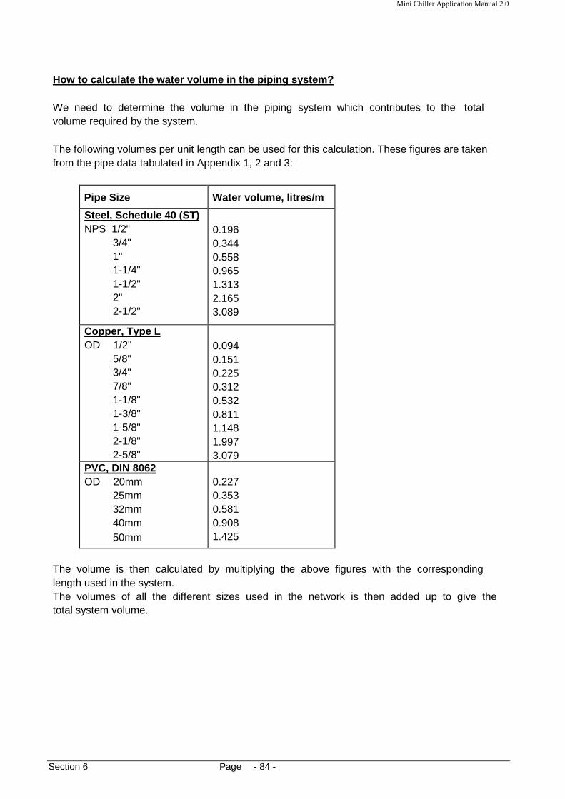
Mini Chiller Application Manual 2.0
Section 6 Page - 84 -
How to calculate the water volume in the piping sys tem? We need to determine the volume in the piping system which contributes to the total volume required by the system. The following volumes per unit length can be used for this calculation. These figures are taken from the pipe data tabulated in Appendix 1, 2 and 3:
Pipe Size Water volume, litres/m
Steel, Schedule 40 (ST) NPS 1/2"
3/4" 1" 1-1/4" 1-1/2" 2" 2-1/2"
0.196 0.344 0.558 0.965 1.313 2.165 3.089
Copper, Type L OD 1/2"
5/8" 3/4" 7/8" 1-1/8" 1-3/8" 1-5/8" 2-1/8" 2-5/8"
0.094 0.151 0.225 0.312 0.532 0.811 1.148 1.997 3.079
PVC, DIN 8062 OD 20mm
25mm 32mm 40mm 50mm
0.227 20 0.353 25 0.581 32 0.908 40 1.425 50
The volume is then calculated by multiplying the above figures with the corresponding length used in the system. The volumes of all the different sizes used in the network is then added up to give the total system volume.

Mini Chiller Application Manual 2.0
Section 6 Page - 85 -
tank body
diaphragm
Connecting pipe
air
water
Downward Installation Horizontal Installation
Expansion Tank In the mini-chiller unit, the expansion tank is located on the storage tank. However, this is only applicable for the conventional C series chillers 23.45 kW to 43.96 kW. For other units; i.e. tandem series, inverter series and larger conventional units, the expansion tank is located on the discharge piping, right after the pump. Generally, the expansion tank provides a space into which the water can expand or from which it can contract as the water undergoes volumetric changes with respect to changes in temperature. Therefore, it is recommended for such an expansion tank to be installed for the smaller mini-chillers when running cooling only cycle, but it is compulsory to do so for the heat pump units with both cooling and heating cycles. Failure to do so will cause serious damage to the hydraulic components in the unit and also may cause cracking of the piping network. This is due to the expansion of the hot water in the pipes. To allow for this expansion or contraction, the tank provides an interface point between the water and a compressible gas (e.g. air or nitrogen). There are 3 types of expansion tank available:
a. A closed tank which contains a captured volume of air and water b. An open tank, i.e. with the water surface open to the atmosphere c. A diaphragm tank, in which a flexible membrane is inserted between the air the water
The expansion tank which is used in the mini chiller units is of type (c). This type is recommended as the diaphragm will prevent the air dissolving into the water.
The tank is usually installed vertically, either upwards or downwards. However, due to space considerations, it is also possible to install it horizontally.

Mini Chiller Application Manual 2.0
Section 6 Page - 86 -
To calculate the size of a diaphragm expansion tank, use the following formula:
Vt = Vs [(v2/v1) - 1] - 3α∆t
1 - (P1/P2) where:
Vt = the tank volume Vs = the water volume in the system v1 = the specific volume of water at lower temperature v2 = the specific volume of water at higher temperature α = the linear coefficient of thermal expansion for the body = 11.7 * 10-6 m/ (m.K) for steel = 17.1 * 10-6 m/ (m.K) for copper ∆t = higher temperature (t2) - lower temperature (t1) P1 = the pressure at lower temperature P2 = the pressure at higher temperature
To size the tank for the heating cycle of the mini-chiller unit, use the lower temperature (t1) as the design chilled water temperature (e.g. 7°C) and the higher temperature (t2) as design hot water temperature (e.g. 40°C). Using the AC 50C as an example, we calculate as follows: Water volume required;
Vmin = 860 * 14.65 * 4 = 168 litres 5 * 60 * 1
At 7°C, the specific volume can be read from the water properties table (App. 11) v1 = 0.001 m3/kg
At 40°C, the specific volume v2 = 0.001008 m3/kg
Use the pressure P2 equivalent to the pressure relief valve setting, e.g. 600 kPa. Use the pressure P1 as the positive pressure at the point of installation, e.g. 80 kPa.
Vt = 168 [(0.001008/0.001) – 1] – (3*11.7*10-6) (40-7) 1-(80/600)
= 1.33 litres (1.59 litres, taking into account a 20% safety factor) Thus, using a 2 litres expansion tank will suffice for the above operation.

Mini Chiller Application Manual 2.0
Section 6 Page - 87 -
tank
Threaded end (e.g.Ø ¾”)
There is an option to also install a ball valve here for servicing purposes.
Tee joint
Reworking the example by using the lower temperature as 0°C and the higher temperature as 80°C, we will get:
Vt = 168 [(0.001028/0.001) – 1] – (3*11.7*10-6) (80-0)
1-(80/600) = 4.88 litres (5.85 litres, taking into account a 20% safety factor) Thus, a 6 litres tank is needed. Therefore, the higher the water temperature, the larger the volume of the tank required. Note: If the tank is located at a location with lower pressure, it can be seen that the
volume required will be smaller. To calculate the expansion tank size for cooling only systems, use the lower temperature as the design chilled water temperature and the higher temperature as the ambient temperature (e.g. 35°C). Generally, the size of the expansion tank for chilled water system is much smaller compared with the hot water applications. Using a larger expansion tank than the calculate requirement is OK. The larger volume will not affect the system; rather it will help to cater for a larger water volume than the value used in the calculation. An expansion tank is not required for an open piping system as the reservoir tank itself will allow for the expansion. There should only be ONE expansion tank in the close piping system.
Installation of External Expansion Tank To install the expansion tank to the water pipe, make a tee-joint at the point of installation. Most tanks have threaded ends for connection purposes.

Mini Chiller Application Manual 2.0
Section 7 Page - 88 -
x
T2
T1
Heat transfer, Q
Section 7: Insulation Material In this section, we will look at the insulation material needed to be used for the chilled water piping installed with the mini chiller unit. The purpose of using the insulation material around the pipe is:
a. To prevent heat gain to or heat loss from the water in the pipes. b. To prevent water condensation along the pipes due to the chilled water flowing in the
pipes c. To prevent injury due to the hot water flowing in the pipes
The type of insulation material used will depend on the pipe material used in the installation. For black steel pipes, it is common to either use closed cell elastomeric insulation (e.g. "Armaflex") or polyurethane foam with external aluminum cladding. For copper pipes, the closed cell elastomeric insulation is used. Similarly, PVC pipes may use the same type of insulation as the copper pipes. It is important that the thickness of the insulation material used for the pipes is sufficient to fulfill the above mentioned requirements. Hence, it is recommended that a calculation check to be made to determine the insulation performance. To do this, the following items must be known:
1. Insulation material thermal conductivity coefficient (k) 2. Pipe Size 3. Air condition (dry bulb temperature and humidity / or wet bulb temperature) at the site of
pipe installation - use the most extreme conditions that exists at the site 4. Convective heat transfer coefficient (h)
The k-value of the insulation material describes how much heat is being conducted through the insulation. A good insulation will have a low k-value. The amount of heat conducted can be calculated as follows:
a. Through a slab of thickness, x
Q = - kA (∆T/x) where:
A = the surface area of the slab
∆T = the temperature difference between the two slab surfaces, i.e. (T1 - T2) with T1 > T2
**This equation is also called as Fourier’s Law

Mini Chiller Application Manual 2.0
Section 7 Page - 89 -
T1
Heat transfer, Q
r2
r1 T2
b. Through a Hollow Cylinder With Internal Radius, r1 and External Radius, r2
Q = 2πkL (T1 - T2)
ln (r2/r1)
where:
L = the length of the cylinder
T1 = the internal surface temperature
T2 = the external surface temperature with T1 > T2 The piping insulation can be considered as a hollow cylinder and the above formula may be used in calculating the insulation thickness. When the heat flux has conducted through the thickness of the pipe insulation, the heat will then dissipate at the external surface by means of convection. The heat transfer rate by convection (Qc) from a surface with temperature T can be expressed as:
Qc = hA (T - Ta) where:
T = the ambient air temperature A = the surface area
By equating the conductive and convective heat transfer equations, it can be shown: r1 * ln (r2/r1) = k (T1 - T2)
h (T2 - Ta) Therefore, with the known k-value and h-value, together with the pipe size (r1) and operating temperature T1, we can calculate the external radius, r2, to obtain a specified external surface temperature, T2.
a. We can thus calculate the minimum required insulation thickness to ensure a safe external surface temperature to protect from the hot water pipe temperature.
b. We can also calculate the minimum required insulated thickness to prevent condensation
by ensuring the external surface temperature is not lower than the dew point temperature of the air surrounding the piping.
Refer to Appendix 12 for a psychometric chart to determine the dew point temperature for different temperatures and humidity levels.
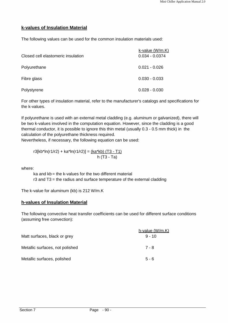
Mini Chiller Application Manual 2.0
Section 7 Page - 90 -
k-values of Insulation Material The following values can be used for the common insulation materials used:
k-value (W/m.K) Closed cell elastomeric insulation 0.034 - 0.0374 Polyurethane 0.021 - 0.026 Fibre glass 0.030 - 0.033 Polystyrene 0.028 - 0.030 For other types of insulation material, refer to the manufacturer's catalogs and specifications for the k-values. If polyurethane is used with an external metal cladding (e.g. aluminum or galvanized), there will be two k-values involved in the computation equation. However, since the cladding is a good thermal conductor, it is possible to ignore this thin metal (usually 0.3 - 0.5 mm thick) in the calculation of the polyurethane thickness required. Nevertheless, if necessary, the following equation can be used:
r3[kb*ln(r1/r2) + ka*ln(r1/r2)] = (ka*kb) (T3 - T1) h (T3 - Ta)
where:
ka and kb = the k-values for the two different material r3 and T3 = the radius and surface temperature of the external cladding
The k-value for aluminum (kb) is 212 W/m.K h-values of Insulation Material The following convective heat transfer coefficients can be used for different surface conditions (assuming free convection):
h-value (W/m.K) Matt surfaces, black or grey 9 - 10 Metallic surfaces, not polished 7 - 8 Metallic surfaces, polished 5 - 6

Mini Chiller Application Manual 2.0
Section 7 Page - 91 -
External metal cladding (spiral wound)
polyurethane
Black steel pipe
Pre-Insulated Pipes These are black steel pipes which have been injected with polyurethane foam together with an external spirally wound metal cladding (aluminum or galvanized iron). Because these pipes have been pre-fabricated, they are widely used in the installation of chillers. The insulation forms a rigid and strong bond with the pipe surface.
Pipes can be joined together with arc welding. Advantages:
a. Due to the strong bond of the polyurethane, there are no air leakages through the insulation and cause internal condensation.
b. The metal cladding gives a good finishing to the installation. Paint can be applied easily over the metal, providing protection against corrosion and giving color codes to the different pipes used.
Disadvantages:
a. High cost. b. Joints with fittings and between pipes require additional insulation molding. This is done
by making a mould with thin metal sheets (aluminum or GI) around the fitting or pipe joint. A mixture of polyurethane chemical and foaming agent is then poured into the mould and allowed to fill the mould.
Pre-fabricated pipe sectional polyurethane can also be used for this purpose, e.g. for elbows and straight pipe joints. An external metal cladding can then be riveted around these sections. As a result of this, the installation of such insulation is more extensive and requires skill.

Mini Chiller Application Manual 2.0
Section 7 Page - 92 -
Sectional Polyurethane As an alternative to the pre-insulated pipes, pre-fabricated sectional polyurethane can be attached onto the bare black steel pipes with an external metal cladding riveted around the pipe. Various shapes and sizes are available to fit the piping network. It is important that a layer of grease to be applied on the internal surface of the polyurethane sections before placing it around the pipe. These sections are then secured tightly around the pipe by tying with metal wire. The layer of grease is to ensure that the sections stick firmly onto the pipe surface and to seal any air gaps, especially at sections' joining surfaces, thus preventing condensation. Even though this method is cheaper compared with the pre-insulated pipe, one major problem is condensation because it is difficult to ensure a complete air-tight installation along the entire pipe length due to the number of sections used. Closed Cell Elastomeric Insulation This type of insulation, made from nitrite rubber, is usually used with copper pipes. Some common names for this type of insulation are Armaflex, Insuflex and Superlon. Tubular form of this insulation is usually used for the copper pipes. However, sheet form is also used to insulate storage tanks, ductwork and steel pipes. This insulation is soft, flexible and easy to install. It can be formed to suit various shapes and sizes. For the tubular form, the insulation can either be slipped-on or snapped-on. Adhesive is then used to stick together all the joining surfaces. It is not needed to stick the insulation onto the pipe itself. Rather, the correct size of the insulation must be used to match the pipe external diameter. Using too large a size will cause air pockets in between the insulation and pipe which will create condensation. A smaller size will not allow the pipe to slip-on or cause incomplete wrap-around during snap-on. See Appendix 13. For the sheet form, adhesive can be used to just stick the insulation onto the surface. Joining edges and corners are also in the same manner. This type of insulation is of the closed cell structure. As compared with the open cell insulation, the closed cell gives better thermal insulation performance and lower water moisture permeability. Absorption of water into the insulation will cause degradation of the thermal conductivity properties over time. Hence, it is not desired for the insulation to retain water.

Mini Chiller Application Manual 2.0
Section 7 Page - 93 -
Example of Selection: The mini chiller has a piping network of diameter 1-1/4". The pipes are to be insulated with Armaflex. The pipes run through a ceiling space with a temperature of 38°C and 85% RH. Determine the minimum insulation thickness required to prevent condensation if the chilled water temperature is at:
a. 7°C b. 2 °C
The Armaflex insulation has a k-value of 0.0374 W/m.K. The tubular insulation has a black surface, thereby use a h-value of 9 W/m.K. By entering into the sizing Excel spreadsheet programme, we calculate:
1. For a 7°C water temperature, the insulation must be at least 1 inch thick. 2. For a 2°C water temperature, the thickness required is 1.1 inch.
It is recommended that the next size up to be selected to provide some safety factor for the selection. If a pre-insulated pipe is used instead, what is the thickness required? Ignoring the effect of the external cladding, and entering again into the programme with a k-value of 0.025 W/m.K, we have the minimum thickness:
1. For 7°C water: 0.7 inch 2. For 2°C water: 0.8 inch
Note that polyurethane is a better thermal insulator compared with the Armaflex, therefore the thickness is lower.

Mini Chiller Application Manual 2.0
Section 7 Page - 94 -
Piping Insulation Thickness Calculation: To Prevent Condensation Air Condition:
DB (°C) 38 Dew Point RH (%) 85 DP (°C) 35.07
Pipe specification:
Pipe diameter (in) 1.25 Radius, r1 (mm) 15.879 Pipe surface temp. (°C) 2
Insulation material: Material = Pre-insulated polyurethane pipe Thermal Conductivity, k = 0.025 W/mK Surface convective heat transfer Coefficient, h = 9 W/m2K Insulation selection: Calculated insulation size, r2 = 37.004 mm Insulation thickness (min) = 21.1mm (0.8 in)
USE THE NEXT SIZE THICKNESS AVAILABLE OR THICKER – FOR SAFETY FACTOR

Mini Chiller Application Manual 2.0
Section 7 Page - 95 -
Piping Insulation Thickness Calculation: To Prevent Condensation Air Condition:
DB (°C) 38 Dew Point RH (%) 85 DP (°C) 35.07
Pipe specification:
Pipe diameter (in) 1.25 Radius, r1 (mm) 15.879 Pipe surface temp. (°C) 7
Insulation material: Material = Pre-insulated polyurethane pipe Thermal Conductivity, k = 0.025 W/mK Surface convective heat transfer Coefficient, h = 9 W/m2K Insulation selection: Calculated insulation size, r2 = 37.004 mm Insulation thickness (min) = 18.5 mm (0.7 in)
USE THE NEXT SIZE THICKNESS AVAILABLE OR THICKER – FOR SAFETY FACTOR

Mini Chiller Application Manual 2.0
Section 7 Page - 96 -
Piping Insulation Thickness Calculation: To Prevent Condensation Air Condition:
DB (°C) 38 Dew Point RH (%) 85 DP (°C) 35.07
Pipe specification:
Pipe diameter (in) 1.25 Radius, r1 (mm) 15.879 Pipe surface temp. (°C) 2
Insulation material: Material = ARMAFLEX Thermal Conductivity, k = 0.0374WmK Surface convective heat transfer Coefficient, h = 9 W/m2K Insulation selection: Calculated insulation size, r2 = 44.980 mm Insulation thickness (min) = 29.1 mm (1.1 in)
USE THE NEXT SIZE THICKNESS AVAILABLE OR THICKER – FOR SAFETY FACTOR

Mini Chiller Application Manual 2.0
Section 7 Page - 97 -
Piping Insulation Thickness Calculation: To Prevent Condensation Air Condition:
DB (°C) 38 Dew Point RH (%) 85 DP (°C) 35.07
Pipe specification:
Pipe diameter (in) 1.25 Radius, r1 (mm) 15.879 Pipe surface temp. (°C) 7
Insulation material: Material = ARMAFLEX Thermal Conductivity, k = 0.0374WmK Surface convective heat transfer Coefficient, h = 9 W/m2K Insulation selection: Calculated insulation size, r2 = 41.440 mm Insulation thickness (min) = 25.6 mm (1.0 in)
USE THE NEXT SIZE THICKNESS AVAILABLE OR THICKER – FOR SAFETY FACTOR

Mini Chiller Application Manual 2.0
Section 7 Page - 98 -
Example no. 2 For heating applications , it is desired to check the insulation thickness required to ensure an external insulation temperature of not more than 37°C. The hot water temperature was found operating at a maximum temperature of 50°C. The pipe size is 1" and the insulation material used is fibreglass encased in a metal cladding. The k-value of the insulation material is 0.035 W/mK. The air temperature around the pipes is 34°C. By entering the data into the Excel spreadsheet programme, we can determine that the insulation thickness required is at least 0.5 inch. It should be noted that the closer the external surface temperature is to the ambient air temperature, the thicker will the insulation be. It is not possible to have the external surface temperature colder than the air ambient temperature, else convection will not occur.

Mini Chiller Application Manual 2.0
Section 7 Page - 99 -
Piping Insulation Thickness Calculation: To Prevent Condensation Air Condition:
DB (°C) 34 RH (%)
Pipe specification:
Pipe diameter (in) 1 Radius, r1 (mm) 12.703 Pipe surface temp. (°C) 50 Insulation surface temp. (°C) 37
Insulation material: Material = Fibre glass Thermal Conductivity, k = 0.0374 W/mK Surface convective heat transfer Coefficient, h = 9 W/m2K Insulation selection: Calculated insulation size, r2 = 24.956 mm Insulation thickness (min) = 12.3 mm (0.5 in)
USE THE NEXT SIZE THICKNESS AVAILABLE OR THICKER – FOR SAFETY FACTOR

Mini Chiller Application Manual 2.0
Section 7 Page - 100 -
Insulation thickness selection can also be made with the manufacturer's recommendations. Please refer to the relevant catalogs or technical manuals. Usually, manufacturers will publish selection tables to suit various temperature applications. Some also have graphical methods for this purpose. Computer selection programmes are also available. See Appendix 14 for an example of a nomograph used by Armaflex. Whatever method is used, it is a good practice to use a thicker insulation size to cater for any unforeseen circumstances. However, this must be balanced with economic consideration as thicker material will cost more.

Mini Chiller Application Manual 2.0
Section 8 Page - 101 -
Section 8: Pipe Support Depending on the complexity of the piping network, various pipe supports are needed to hold and support the piping along its route. Such supports will include hangers, saddles, trays, brackets, anchors, etc. These supports must be strong enough to withstand all static and dynamic load conditions, which include:
a. The weight of the pipe, fittings, valves, water and insulation material b. Wind, ice and seismic forces (where applicable) c. Vibrations and water hammering d. Forces imposed by thermal expansion and contraction of the pipe bends and loops
Generally, the pipes from the mini chiller unit are run along the ceiling space, along wall surfaces, through floor slabs, through walls and also along the floor level. The following diagrams give suggestions on how various pipe supports are used for the different type of applications. Other than that, the number of supports must be sufficient along the pipe length to prevent the pipe from sagging. The spacing between supports will depend very much on the pipe material and the pipe size. "Softer" pipes, e.g. PVC and copper, will require shorter support spans. Refer to the attached table for suggestion of this support/hanger spacing.

Mini Chiller Application Manual 2.0
Section 9 Page - 102 -
(e.g. sand bed type filter, compacted gravel type, etc.)
Strainer
Water filter
Make-up water supply
Section 9: Water Side Treatment The brazed plate heat exchanger (BPHE) which is used in the mini chiller unit consists of several stainless steel plates brazed together to form two distinct flow channels in between each successive plates. Water flows in one channel and refrigerant in the other, usually in a counter flow direction. Because the spacing in between the plates is small, it is vital that these flow channels (especially the water side) are not blocked by debris, fouling or scaling. Such impurities will restrict the flow rate and reduces the chiller performance. Furthermore, the heat transfer efficiency will be retarded.
Generally, debris in the water (e.g. sand, gravel, metal pieces) will be removed by the strainer installed along the water suction pipe. This will depend on the filter mesh size used in the strainer itself. A filter mesh size of 16 - 20 is recommended for this purpose. Nevertheless, it is also a good practice to install another water filter along the make-up water supply pipe for the same purpose. It is important that these filter elements to be serviced periodically to remove any trapped particles and debris inside them. Flushing of the pipes periodically with water is also a good maintenance practice.
Usually, such coarse debris is found during initial start-up and commissioning of the mini chillers. This debris is left-over during the installation of the water piping. Therefore, it is recommended that a thorough flushing with clean water to be done in the water piping before the chiller is started. Check and clean the strainer element also before start-up. Fouling refers to the tendency of the water to form a film on the heat transfer surfaces. There are two types of fouling:
a. Organic surface fouling b. Inorganic surface fouling
Mini Chiller Application Manual 2.0
Section 9 Page - 103 -
The organic fouling includes microbiological growth or slime on the surfaces of the heat exchanger plates and pipes. Algae may also form on these surfaces. This type of fouling is more significant in open systems whereby oxygen dissolved in the water through the open storage tank will encourage the microbiological growth.
Scaling is a type of inorganic fouling. It is caused by deposit of inorganic salts (e.g. calcium sulfate, calcium carbonate) in the water onto the heat exchanger plate surfaces and pipes. Such phenomenon occurs when the water temperature gets higher, usually > 50°C. This is because the solubility of the salts becomes lower when the temperature becomes higher. When coupled with low water velocities (laminar flow) and uneven flow distributions (e.g. at areas of water stagnation in the heat exchanger), a thin hard layer of scaling will form on the surfaces.
Generally, scaling is not a problem with chilled water systems.
Symptoms:
1. A heat exchanger which has been choked with coarse debris will normally exhibit a sudden increase in pressure drop. This is due to the sudden block of water flow by the debris.
2. Both the organic and inorganic surface fouling will show a gradual increase of pressure
drop and a gradual drop in the heat exchanger performance. Remedy
For both the above symptoms, it is necessary to remove all these fouling material in order to have an optimum chiller performance. We have mentioned earlier that the coarse debris is relatively easy to remove by cleaning the filter elements and flushing out with water. Nevertheless, sometimes some of the larger debris may be stuck in between the plates.
If such blockages are too severe, it may be necessary to change a new BPHE altogether. For both the surface fouling, a chemical cleaning is needed to remove them.
a. Organic fouling
Use an alkaline cleaning agent like caustic soda or sodium hydroxide (NaOH) at a 5% concentration. Mix with clean water and then pump in the solution into the heat exchanger and piping system. An external circulator pump may be used for this purpose. Refer to the chemical manufacturer recommendations for directions of usage. Additional surface active substances may need to be added into the mixture for better cleaning performance. After cleaning, flush the whole system with clean water to remove any excess chemical.

Mini Chiller Application Manual 2.0
Section 9 Page - 104 -
b. Inorganic fouling
The most commonly used cleaning agent for scaling problems is acid. Mineral acids have a strong ability to dissolve the scales. But these can also corrode the steel and copper material in the system. Such acids include sulfuric acid, hydrochloric acid and nitric acid. However, these acids will also attack/corrode the stainless steel, gaskets and copper parts. Organic acids are weaker than the mineral acids in the corrosive properties but still able to dissolve the scales. This makes them ideal when used to clean the BPHE. Such acids include phosphoric acid, formic acid and acetic acid. Usually, this acid is used in combination with other chemicals to enhance the cleaning capabilities. Whatever type of acids used, care must be taken in handling the chemical. A concentration 2% to 5% should be mixed and circulated into the system. An additional inhibitor chemical may be added, if necessary, to diminish the corrosive action onto metals. Refer to the chemical manufacturer recommendations on the required dosage to use. Upon completion, flush with lots of clean water to remove any excess acids. Depending on the directions of usage, some may require neutralization and passivation after cleaning. Example of Cleaning chemicals:
a. AIfaCaus : sodium hydroxide for cleaning of organic fouling
b. AIfaPhos : phosphoric acid (organic acid)
c. AIfaCarbon : formic acid (organic acid)
d. Kaloxi : citric acid, phosphoric acid
e. P3-T 288
f. Nitric acid (1 %) + P3-stabicipNA (inhibitor)

Mini Chiller Application Manual 2.0
Section 9 Page - 105 -
Water outlet
Water inlet
Refrigerant inlet
Refrigerant outlet
Entering water sensor position; ½” female socket
Anti-freeze sensor position; ½” female socket
BRAZED PLATE HEAT EXCHANGER
Recommendations for Cleaning It is recommended that the cleaning chemical to be pumped directly into the BPHE, which will also re-circulate into the piping network. Flush out all water from the piping system.
Remove the entering water sensor and anti-freeze sensor from the BPHE. Connect the supply and discharge tubing/hose from the cleaning chemical pump to the BPHE (via 1/2" female sockets).
Do not run the water pump in the mini chiller unit. Run the cleaning pump for 10 to 15 minutes unless otherwise instructed by the chemical manufacturer. Refer to cleaning instructions provided by the manufacturers.
Drain away the cleaning chemical. If necessary, a neutralizing agent (e.g. sodium hydroxide) can then be pumped in a similar manner. Refer to the chemical manufacturer's instructions. After cleaning, flush out with clean water through the BPHE. Refill the buffer tank in the unit and run the water pump to re-circulate through the piping system. Drain and refill until all the cleaning chemicals are flushed out. It is also possible to allow the pump to push out water through the entering water sensor socket.
Mini Chiller Application Manual 2.0
Section 9 Page - 106 -
Periodic maintenance It is a good practice to have a periodic maintenance for the mini chiller, especially on the water side. Check the water quality regularly. Drain out some water from the buffer tank and observe for excessive impurities and rust. For open systems, this can be done from the reservoir tank. If the water is dirty (e.g. dark brown in color), drain away the water and refill with clean water. It is recommended that the water to be replaced at least once a year to prevent fouling on the BPHE. If the water quality is poor, this should be done more regularly. Close monitoring will be required.

Mini Chiller Application Manual 2.0
Section 9 Page - 107 -
Glycol Solutions As mentioned earlier, the mini chiller has two water sensors at the BPHE:
a. Water Entering Temperature Sensor
This is a temperature set-point for cooling and heating. The cooling has an adjustable range of 7 to 20°C. Refer to the Technical Manual for more details on this adjustment. However, if required, this can further be adjusted down to -20°C, i.e. with a leaving water temperature of approximately -25°C. Such requirements are usually needed for process cooling whereby sub-zero water temperatures are used for cooling of machines and equipment. It is recommended to consult trained technicians or service personnel to perform this adjustment.
b. Anti-Freeze Sensor
It is also the leaving water temperature sensor. This sensor will protect the water temperature from becoming too low and freezes up. Formation of ice in the BPHE will cause it to crack due to expansion. Therefore, as the sensor reaches the anti-freeze heater set-point, the heater will be activated to heat up the BPHE. If the water temperature continues to drop despite the heating process, the antifreeze alarm will trigger. The factory setting for the anti-freeze set point is 5°C and the alarm is 3°C. However, if required, this can be further adjusted when used in special process cooling applications. Again, consult trained technicians to do this adjustment.
Because of the danger of the water becoming ice, special precautions must be taken:
1. For sub-zero applications, the water must be mixed with anti-freeze glycol solution. There are two commonly used types: ethylene glycol and propylene glycol. In some instances, brine (sodium chloride) is used.
Whatever type is used, the quantity mixed with the water must be sufficient to reduce the water freezing point to cater for the operating water temperature in the process cooling. It is recommended the freezing point is at least 3°C below the operating temperature. For example, if a temperature of -2°C is required, we need to ensure that the water freezing temperature is at least -5°C to prevent ice formation. Looking at the property table of ethylene glycol, the mixture should have about 13% glycol by volume in order to have the required freezing point. See Appendix 15. If propylene glycol is used, the percentage should be about 14.5% by volume. The minimum operating temperature of ethylene glycol is -23°C and of propylene glycol is -18°C. The lower water freezing temperature is required, the higher concentration of glycol must be used. However, the viscosity of the mixture will increase, thus increasing pumping power requirements and reducing heat transfer efficiency. High concentrations of glycol will also increase costs and adversely affect the physical properties of the fluid.
2. Make sure that the water pump is ON all the time the chiller is in use. This will ensure no
stagnation of water in the BPHE which reduces the risk of ice formation.
Mini Chiller Application Manual 2.0
Section 9 Page - 108 -
Aqueous solutions of glycol are corrosive to metals and therefore it must be used with an inhibitor. This corrosion inhibitor forms a surface barrier that protects the metal from attack. The inhibited glycol solution is generally stable and relatively non-corrosive to most standard materials. The exception is galvanized steel because the zinc coating will react with the inhibitor part found in most formulated inhibited glycol sold commercially.
Performance effects of glycol solutions:
a. Higher concentrations of glycol will retard heat transfer coefficient in the BPHE. For example, a 30% glycol concentration may cause a drop of capacity by about 20%. Refer to the attached graph depicting this drop of performance (Appendix 16).
b. As the concentration increases, the viscosity of the solution also increases. Therefore,
the friction losses of the piping system will also increase. A correction factor must be used to evaluate this increase. See Appendix 16.
c. Similarly, the viscosity increase will also affect the water pump performance. The flow
rate and efficiency will reduce with higher concentrations. Thus, the head pressure developed will also drop. See also Appendix 16.
Due consideration of these effects must be given when designing and selecting the chiller unit for such a system. Failure to do so may result in insufficient capacity and water flow rate.
Guidelines:
1. Before applying the glycol solutions, thoroughly clean and flush the system. Reaction
with sludge, rust, deposits and oil may retard the inhibitor function. This is especially so after using cleaning agents in the BPHE. Complete removal of the cleaning agent is necessary before charging in the glycol.
2. Calculate the total water volume in the system and determine the amount of glycol
needed. The solution can be mixed outside the system in drums or barrels and then pumped into the system. Use clean and soft water (low in chloride and sulfate ions) for the mixing. Distilled water, de-ionized water or condensate water may be used for this purpose.
3. The system must not be connected to an automatic make-up water pipeline. This may
cause dilution of the concentration and increases the water freezing point. The inhibitor portion in the solution may also deplete over time due to reaction with contaminants in the system. Therefore, it is vital that a maintenance programme is in place to determine the glycol concentration in the system. This can be measured by using refractometer (which measures the refractive index of the solution), gas chromatography or density bottle (though not so accurate).
4. Do not mix different inhibited glycol formulations together.
Mini Chiller Application Manual 2.0
Section 10 Page - 109 -
Section 10: Heating Operation In most of our discussion in the previous sections, emphasis has been given to the cooling operation whereby the mini chiller produces chilled water. The heat pump version of the mini chiller (designated with "R" at the end of the model name, e.g. AC 50CR, AC 120CR, AC 80CR can operate both under the cooling mode and heating mode, i.e. it can produce either chilled water or hot water. The heating cycle is run during the cold, winter months. Operation of the heating cycle is accomplished by reversing the refrigerant flow in the circuit with a 4-way valve. By doing so, the BPHE becomes the condenser which rejects the heat absorbed from the ambient air into the water. The mini chiller has been designed with a rated water entering and leaving temperatures of 40°C and 45°C respectively in the heating cycle. (Compare rating for the cooling cycle at 12°C and 7°C for entering and leaving temperatures) The maximum allowable entering water temperature is 50°C, i.e. corresponding to a leaving temperature of 55°C. The mini chiller has also been designed to operate the heating cycle with an ambient temperature range of -5°C to 15°C. Because of the higher water temperature, several precautions must be taken into consideration when using this system: Application considerations:
1. In multiple chiller installation, all the chillers must either run in the cooling mode or heating mode. We cannot have a few units running cooling cycle while the rest running heating cycle because this may damage the compressor as a result of overloading.
2. In the same manner, in multiple fan coil units installation with a single mini chiller, the wiring
of the system must be in such a way to have all the fan coil units either in cooling mode or heating mode.
3. Do not use PVC pipes for such heating systems. PVC is OK for chilled water but long term
usage with hot water will soften and weaken the material. Most of these pipes will exhibit sagging in between supports after some time. It is recommended that black steel or copper pipes to be used instead.
4. Any gaskets, sealants or insulation material used in the piping system must able to withstand
temperatures of at least 60°C without degradation of their physical properties.
5. Recheck again the pipe insulation thickness which has been sized for the cooling cycle to prevent condensation. In the heating cycle, the insulation thickness must be sufficient to have a safe handling surface temperature (e.g. 30 to 35°C).

Mini Chiller Application Manual 2.0
Section 10 Page - 110 -
6. As a result of the reverse cycle, the finned tube heat exchanger coil will now act as an evaporator in the heating cycle. Therefore, moisture removal will occur at this coil and the water will flow down to the ground. Care must be taken for proper drainage of this water. Do not allow this condensate water to drip onto live wire parts. Do not allow this water to form puddles and submerge wire cables.
7. As mentioned in Section 9, scaling of the BPHE becomes more prevalent with hot water
systems (temperature >50°C). A more regular monitoring of the pressure drop across the BPHE is required to check for fouling. A better periodic maintenance programme may be necessary.
8. Check the pump specifications whether it can operate at the required operating
temperature.
The pumps have a maximum fluid temperature of 90°C. It is also a good practice to counter-check again the NPSHA for the pump with the higher water temperature. This is because the vapour pressure of water will increase and in turn will reduce the NPSHA. Refer to Section 5. Therefore, the risk of cavitation occurring in the pump is higher with hot water systems. Adjustments to the system may be necessary for a safe operation.
9. The hot water will cause expansion of the pipes. The linear thermal expansion for
carbon steel and copper changes as follows:
Temperature, °C Linear thermal expansion, mm/m Carbon steel Copper
0 0.20 0.31 10 0.32 0.47 49 0.76 1.14
Increase with respect to 0°C 2.8 times 2.7 times
Therefore, it is important that the piping installed with the supports must have sufficient flexibility to allow for the expansion. A general practice is to never anchor a straight pipe run at both ends. Pipe bends and loops are excellent to absorb such "shape changes" due to expansion and contraction. Rubber expansion joints can also be installed along the piping for the same purpose. During operation of the heating cycle, check for any piping deformation. Check also for failure of any pipe supports and leakage due to cracking.

Mini Chiller Application Manual 2.0
Section 10 Page - 111 -
Downwards to drain
piping
Safety valve
10. Perhaps the most important function that occurs during the heating cycle is the defrost function. Operation of heating cycle under sub-zero ambient temperatures will cause the evaporator condensate to ice-up on the fin surfaces. The ice/frost will retard heat transfer and reduces the chiller performance. Therefore, the microprocessor controller in the mini chiller will initiate a defrost cycle to melt off the ice by momentarily switching the system back to a cooling cycle. During this time, the finned tube heat exchanger will become the condenser and gets heated up to melt off the ice. Once completed, the chiller will again revert back to heating cycle.
During the defrost cycle, there will be a lot of water dripping down from the unit. Always ensure proper drainage of this water. See Clause 6 of this section.
When running the defrost cycle initially, there may be instances whereby the controller will trip the chiller. Check the nature of fault from the controller LCD display (e.g. "High Pressure" or "Low Pressure"). Refer to the Trouble Shooting table in the Technical Manual for remedial actions. It may be necessary to consult trained service personnel to perform some minor adjustments to optimize this defrost cycle.
11. It is an option whether to install or not a safety pressure relief valve into the pipe system. It
is recommended for safety purposes, but this will increase the cost of installation.
Such valves are useful to protect against overheating of water when the other safety protection features in the chiller unit (i.e. water temperature sensor, compressor overload protector, high pressure switch) have failed. A reasonable setting of pressure should be selected to ensure a smooth operation under the highest operating temperature without any nuisance trips. All mini chillers are equipped with a 600 kPa auto pressure relief valve.
Note: Other than overheating, the safety relief valve will also protect the system from
a) over-pressurizing from make-up water system and b) shock from water hammer.
The safety relief valve must exhaust to a suitable drain. Install the drain pipe downwards from the valve into a drain. Horizontal drain pipes can cause injury due to the spitting of hot water. The safety valve is usually installed at the highest point of the pipe system and/or near the water make-up connection.

Mini Chiller Application Manual 2.0
Section 10 Page - 112 -
12. Before purging or releasing hot water from the chiller unit, allow sufficient time for the water to cool down first. Water temperature of 40 to 50°C can cause injury to the body. Remember also that the hot water will be under a higher pressure and sudden opening of drain valves may cause spitting out of hot water.
External boiler installation In some instances, the heating capacity of the mini chiller unit is not sufficient for an application. Therefore, to supplement the heating capacity, two methods can be used:
1. Electric heater
1-phase or 3-phase electric heaters can be installed into the fan coil units or into the duct work itself to generate the extra heating capacity required. However, proper installation of the heaters must be done to prevent risk of fire. Due to the high amperage of the heaters, suitable cable size must be used. The heaters must interlock with the fan coil blowers whereby the heaters will not switch on as long as the blower is off. This is to prevent overheating. Thermostats must also be installed near the heaters to cut-off the heaters when the temperature gets too hot. Generally, heaters are easy and convenient to use. However, the operating cost of the electricity consumed is high.
2. Hot water boiler (diesel fired, fuel oil fired or gas fired)
Boilers can handle larger heating loads with a lower operating cost when compared with heaters. With proper installation and maintenance, boilers can be made to run with high efficiencies. Nevertheless, the operation of the boiler is more complex. Safety requirements are higher. The safe operation of boilers is beyond the scope of this manual. Please refer to the boiler manufacturers for more details and information. There are several methods available to run the piping between the boiler and the mini chiller unit, together with the fan coil units. This will depend on the design requirements of a particular system. Only 2 common methods will be discussed here:
a. 2-pipe system
In this method, the boiler is connected with a cooling only mini chiller unit. A 3-way diverting valve is piped along the discharge line from the chiller to the fan coil units. All fan coil units must required either cooling or heating loading. It is not possible to have some fan coils in cooling and some in heating. However, the boiler will take up all heating load which cannot be supplied by the mini chiller unit.
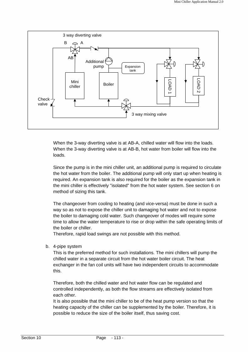
Mini Chiller Application Manual 2.0
Section 10 Page - 113 -
LOA
D 1
Mini chiller Boiler
Expansion tank
AB
A B
3 way diverting valve
Additional pump
LOA
D 2
Check valve
3 way mixing valve
When the 3-way diverting valve is at AB-A, chilled water will flow into the loads. When the 3-way diverting valve is at AB-B, hot water from boiler will flow into the loads. Since the pump is in the mini chiller unit, an additional pump is required to circulate the hot water from the boiler. The additional pump will only start up when heating is required. An expansion tank is also required for the boiler as the expansion tank in the mini chiller is effectively "isolated" from the hot water system. See section 6 on method of sizing this tank. The changeover from cooling to heating (and vice-versa) must be done in such a way so as not to expose the chiller unit to damaging hot water and not to expose the boiler to damaging cold water. Such changeover of modes will require some time to allow the water temperature to rise or drop within the safe operating limits of the boiler or chiller. Therefore, rapid load swings are not possible with this method.
b. 4-pipe system This is the preferred method for such installations. The mini chillers will pump the chilled water in a separate circuit from the hot water boiler circuit. The heat exchanger in the fan coil units will have two independent circuits to accommodate this. Therefore, both the chilled water and hot water flow can be regulated and controlled independently, as both the flow streams are effectively isolated from each other. It is also possible that the mini chiller to be of the heat pump version so that the heating capacity of the chiller can be supplemented by the boiler. Therefore, it is possible to reduce the size of the boiler itself, thus saving cost.

Mini Chiller Application Manual 2.0
Section 10 Page - 114 -
Boiler
Expansion tank
LOA
D 1 (H
EA
T)
LOA
D 2 (H
EA
T)
LOA
D 2 (C
OO
L)
LOA
D 1 (C
OO
L)
Mini Chiller
A water pump and expansion tank is also required for the hot water system. By this configuration, we can have the cooling coil in the fan coil unit for humidity control of the air and the heating coil to reheat the air. Nevertheless, this method is more expansive as the pipe network is more extensive.

Mini Chiller Application Manual 2.0
Section 11 Page - 115 -
Section 11: Electrical Wiring Control The mini chiller unit has a PCB (printed circuit board) microprocessor controller to operate the unit. The function of the controller is:
a. to sequentially ON/OFF the compressor, fan motor and pump according to the water temperature settings and operation mode settings.
b. to protect the chiller from operating beyond the maximum pressure and temperature limits specified.
c. to initiate and terminate the defrost cycle (heating mode only). A power supply connection is required to operate the chiller unit. Models ranging from 5.86kW to 8.78kW require 1-phase AC power supply (220-240VAC/50Hz). The models from 11.71kW and above will required a 3-phase AC power supply (380-415VAC/50Hz). The tandem series is convertible between 1-phase and 3-phase supply. The PCB will use this power and convert it to a 12V DC supply to operate the electronic components on the board. By using relays and switches on the board, the PCB will thus perform the above mentioned functions. See the Technical Manual for detailed wiring diagram of the PCB and internal wiring of the chiller. To connect the power supply cord, insert the cord into the hole on the chiller unit labeled “Power Cable”. Connect them to the terminal blocks or switch breaker provided in the control box (R, S, T, N and Earth) or (L, N, Earth) for 1-phase. Other than that, several interconnecting cables are required between the mini chiller and the indoor fan coil units. For all models, it is recommended the size of these interconnecting cables to be of size 1.5 mm2. How these interconnecting cables are wired-up will depend on how the system has been designed to operate.

Mini Chiller Application Manual 2.0
Section 11 Page - 116 -
Drain holes
Guidelines for wiring installation:
1. Use ring type cable lugs for all termination of cables at terminal blocks. It is not recommended to use fork type cable lugs.
Note #: Refer to the unit nameplate for the required power supply.
2. All external wires must be placed inside a trunking or conduit pipe for protection purposes. Ensure sufficient support for the trunking or conduit so that there is no sagging. It is recommended to use galvanized steel trunking and conduit pipe for external use. Do not use PVC wire conduits. It will become brittle after long exposure to sunlight.
3. Do not allow water (e.g. condensate water) to drip onto the wires. This could lead to
electrical shocks.
Do not allow rain water to accumulate inside an exposed wire trunking. It is a good practice to drill some drain holes at the bottom of the trunking to drain out any water.
4. Do not run the wires beneath the chiller unit. Condensate from the heat exchanger or
during the defrost cycle may drip down onto the wires.
5. Do not run the wires through a location which may accumulate water, especially after rain.

Mini Chiller Application Manual 2.0
Section 11 Page - 117 -
Ring cable lug
Spring washer
Welded nut
Earthwire
Metal part
Earth terminal bolt (M5)
6. It is vital that the chiller unit has proper Earthing. Make sure that the Earth wire is present and connected. In some models, the Earth wire is connected to a terminal block. In others, an Earthing nut terminal is provided on control box metal part. The wire must be screwed on tightly with sufficient force so that the spring washer beneath the screw will securely hold the cable lug.

Mini Chiller Application Manual 2.0
Section 11 Page - 118 -
Wiring configuration For the C series model, the controller PCB is mounted inside a control box and all necessary wiring terminations are made available via terminal blocks for field connections. The following pages will describe some examples of the wiring configuration between the mini chiller and fan coil units. More information is available in the Installation and Operation Manual. Please note the following items for these examples: The wired Chiller Panel controller has a standard wire length of 2 meter. The wire length can be extended (field supply) to 15 meter to allow mounting at the indoor room. With this remote controller, all the chiller parameters are set and the chiller performance can be monitored. The option Alarm LED from terminal AL IN and AL OUT is meant to be installed into the switchboard. It acts as a visual indication if an abnormal operation has occurred. The PCB will give out a signal to light up the LED when any of the protection devices tripped. The remote option O/F (on/off) and C/H (Cool/Heat) may be located at a convenient place for easy access to the user. It may be placed inside the switchboard. It can also be an emergency switch to stop the chiller unit. The power supply for the fan coil units are separated from the mini chiller. More information on wiring configuration for the mini chiller and fan coil unit is available in the Installation Manual.

Mini Chiller Application Manual 2.0
Section 12 Page - 119 -
BPHE WATER OUT
WATER IN
Flow switch
Section 12: Flow Switch The function of the flow switch is to switch off the chiller unit when a low water flow rate condition is detected in the piping. Such occurrences may happen due to:
1. pump failure 2. blocked BPHE 3. accidental closing of shut-off valves 4. failure of control valves
This protection against low water flow rate is necessary to prevent the water from freezing in the BPHE. Ice formation in between the plates in the BPHE will cause frost cracked. Normally, the flow switch installed in the piping, at the following location:
The flow switch is of the paddle type whereby the switch is connected mechanically to a length of stainless steel paddles which the water flow will impact upon. As a result, the paddle will move in the flow direction and thus closes the electrical contact. The length of the paddles can be adjusted by selecting the number of segments to use. The paddles can also be trimmed with a pair of scissors to suit requirement.
FLOW
Flow switch
Paddle segments

Mini Chiller Application Manual 2.0
Section 12 Page - 120 -
The length of the paddles is very important:
a. If the length is too short, the switch may not contact or if the flow rate is very strong, the paddle may deform.
b. If the length is too long, the paddle may touch the internal surface of the pipe and becomes stuck inside.
As a general rule of thumb, the length of the paddle should be at least 5mm above the bottom of the pipe surface.
The flow switch is also mounted vertically with the paddles in a downward position. It is screwed into the connecting piping via a tee adaptor.
The switch in the flow switch is a SPDT (Single Pole, Double Throw) type. It has a common terminal and two contacts. One contact will activate when there is an increase in flow, whereas the other will activate when there is a decrease in flow. Each flow switch will have its own 'activation' flow rate setting. Appendix 17 gives an example for such settings for a Johnson Controls model F61 flow switch.
FLOW Screw thread: apply PTFE white tape
Tee-joint
At least 5 mm distance
PIPE
Paddles

Mini Chiller Application Manual 2.0
Section 12 Page - 121 -
Note: We can also call the 'decrease' contact as Normally Close (NC) contact whereas the 'increase' terminal as Normally Open (NO) contact. When water flows through, the NC contact will open and the NO contact will close. In the mini chiller unit, the NO contact is connected to the PCB controller via the FS terminal. When the contact closes, a 12V signal is received by the controller indicating that the water flow is OK. When the contact opens, the absence of this signal will prompt the controller to give an error code 'flow switch error (FL)' on the LCD display. Some of the typical problems encountered when the FL error code occurred are:
a. the paddle has broken/cracked/twisted b. the paddle has stuck in the pipe c. the switch mechanism has jammed - e.g. due to debris d. wrong wiring of the NO and NC terminals (reversed) e. failure of the switch contacts - e.g. due to shorting f. wrong adjustment setting of the switch g. air lock in the water pump g. insufficient water in the system
In the event that the flow switch must be replaced:
1. Drain out all the water in the system. 2. Remove the wiring connections in the switch and remove the switch from the tee adaptor. 3. Replace with a new switch and reconnect the wire. Manually test the switch by pushing the
paddle. If it is OK, there should be an audible 'click' sound. Check sufficient length of paddles. Screw the switch back into the piping.
4. Refill the system with water. Purge out any air by releasing the air lock hole on the pump. 5. Check for water leakage. 6. Test run and confirm switch operation.
SPDT INCREASE (NO)
COMMON
DECREASE (NC)
Mini Chiller Application Manual 2.0
Section 12 Page - 122 -
Adjustments The flow switch comes with a factory pre-set setting. Due to the different applications at site, it may be necessary to perform some adjustments to the flow switch to allow it to function properly. Such adjustments are done to cater for the flow rate requirements. To do this, turn the adjustment screw clockwise or anticlockwise with a screwdriver. For the F61 switch, this screw is located next to the SPDT switch. This screw is to adjust the spring tension which holds the switch together. Turning the screw clockwise will release the spring tension; therefore, a lesser flow rate will activate the switch. Conversely, turning the screw anticlockwise will increase the spring tension; therefore a greater flow rate is needed to activate the switch. It is recommended that during trouble-shooting of the flow switch, this screw adjustment is checked for wrong settings which could cause the system to trip. Weather proofing Since the flow switch is exposed to the external elements, and also because of the wet operating environment, it is vital that the flow switch cover is screwed on tightly and properly. For the F61SB model, the cover comes with a piece of rubber gasket around the edges to prevent moisture from entering the switch. Do not remove this gasket from the cover! Make sure that the gasket is seated correctly along the edges before the four screws are tightened. Some flow switches have an 'inverted cup' cover which prevents entry of moisture into the switch. Such switches do not have a gasket. Nevertheless, it is vital that the cover sits properly and the holding screws tighten securely. Example of this is the F61KB model. In the same manner, care must be taken that the incoming cable into the switch is sufficiently sealed to prevent moisture from entering the switch. Failure to do so may cause shorting of the terminals and corrosion of the internal parts of the switch.

Mini Chiller Application Manual 2.0
Section 12 Page - 123 -
BPHE
WATER OUT
WATER IN
differential pressure switch
Another type of flow switch which is used in the mini chiller units is the differential pressure flow switch. This flow switch works by measuring the difference in pressure between the inlet and outlet to detect the flow. The schematic diagram is as follows:
The main advantages of using this type of flow switch are:
a. It does not have moving parts, i.e. it is more rugged and reliable b. It does not require any adjustments c. The internal parts are sealed, i.e. it has good water-proofing.
The differential pressure flow switch has three wires coming out of it, i.e. common, normally open (NO) and normally closed (NC). The wiring in the chilller has been configured whereby the common and normally open (NO) wires are connected to the PCB. This means that when there is sufficient water flow, the switch contact will close to give a 240VAC signal to the PCB. Connection of the switch to the water pipe is done with two 1/4” copper tubes, screwed in with threaded couplings to access valves. This facilitates easy replacement of the switch as it is not necessary to drain away all the water in the system during servicing. However, it is necessary to shut down the system in order that the water does not spatter from the access valves.
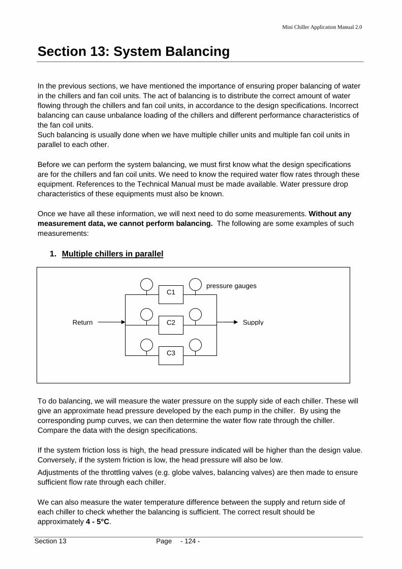
Mini Chiller Application Manual 2.0
Section 13 Page - 124 -
C1
Return Supply
pressure gauges
C2
C3
Section 13: System Balancing In the previous sections, we have mentioned the importance of ensuring proper balancing of water in the chillers and fan coil units. The act of balancing is to distribute the correct amount of water flowing through the chillers and fan coil units, in accordance to the design specifications. Incorrect balancing can cause unbalance loading of the chillers and different performance characteristics of the fan coil units. Such balancing is usually done when we have multiple chiller units and multiple fan coil units in parallel to each other. Before we can perform the system balancing, we must first know what the design specifications are for the chillers and fan coil units. We need to know the required water flow rates through these equipment. References to the Technical Manual must be made available. Water pressure drop characteristics of these equipments must also be known. Once we have all these information, we will next need to do some measurements. Without any measurement data, we cannot perform balancing. The following are some examples of such measurements:
1. Multiple chillers in parallel
To do balancing, we will measure the water pressure on the supply side of each chiller. These will give an approximate head pressure developed by the each pump in the chiller. By using the corresponding pump curves, we can then determine the water flow rate through the chiller. Compare the data with the design specifications. If the system friction loss is high, the head pressure indicated will be higher than the design value. Conversely, if the system friction is low, the head pressure will also be low.
Adjustments of the throttling valves (e.g. globe valves, balancing valves) are then made to ensure sufficient flow rate through each chiller. We can also measure the water temperature difference between the supply and return side of each chiller to check whether the balancing is sufficient. The correct result should be approximately 4 - 5°C.

Mini Chiller Application Manual 2.0
Section 13 Page - 125 -
FCU1
Return
Supply
balancing valve
FCU2 FCU3
FCU
Flow meter
F
Globe valve
2. Multiple fan coil units: direct flow rate measur ement
To directly measure the flow rate, we need to install balancing valves into each of the fan coil units. Each balancing valve will have an inlet and an outlet port to allow connection to a pressure meter. By measuring this pressure drop across the valve itself, the flow rate can be determined by using the valve calibration charts. See Appendix 18 for an example. Compare these data with the design specifications. Adjust the balancing valves where necessary to obtain the required flow rate. Note 1: It is also possible to install a flow meter along the supply line together with a globe valve, to perform the same function as above. An orifice type flow meter may be suitable in such case.
Note 2: The balancing valves can also be installed for the multiple chillers as in example 1 above to measure the flow rate.
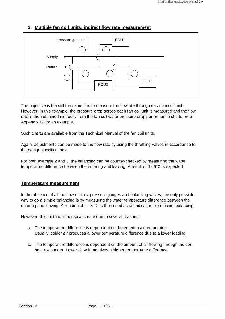
Mini Chiller Application Manual 2.0
Section 13 Page - 126 -
FCU1
Return
Supply
pressure gauges
FCU2 FCU3
3. Multiple fan coil units: indirect flow rate meas urement
The objective is the still the same, i.e. to measure the flow ate through each fan coil unit. However, in this example, the pressure drop across each fan coil unit is measured and the flow rate is then obtained indirectly from the fan coil water pressure drop performance charts. See Appendix 19 for an example. Such charts are available from the Technical Manual of the fan coil units. Again, adjustments can be made to the flow rate by using the throttling valves in accordance to the design specifications. For both example 2 and 3, the balancing can be counter-checked by measuring the water temperature difference between the entering and leaving. A result of 4 - 5°C is expected. Temperature measurement In the absence of all the flow meters, pressure gauges and balancing valves, the only possible way to do a simple balancing is by measuring the water temperature difference between the entering and leaving. A reading of 4 - 5 °C is then used as an indication of sufficient balancing. However, this method is not so accurate due to several reasons:
a. The temperature difference is dependent on the entering air temperature. Usually, colder air produces a lower temperature difference due to a lower loading.
b. The temperature difference is dependent on the amount of air flowing through the coil
heat exchanger. Lower air volume gives a higher temperature difference.

Mini Chiller Application Manual 2.0
Section 14 Page - 127 -
Section 14: Chiller Shut Down The following procedures must be considered when the mini chiller is shut down for long periods of time:
1. Do not totally disconnect the power supply to the chiller unit. This will allow the compressor crankcase heater to energize and prevent refrigerant migration during the shut down period.
2. The chiller is most vulnerable at shut down during cold weather conditions where there is
a danger of the water in the pipes freezes up. To help prevent this from happening:
a. Set the chiller into the STANDBY mode (i.e. no mode selection on the controller). In this mode, the controller will force ON the water pump when the ambient air is lower than 5°C. At the same time, the BPHE anti-freeze heater will also energize to heat up the water. If the air temperature goes lower than 2°C, the controller will force ON the chiller unit to go into HEATING mode. Therefore, the power supply to the chiller unit must not be switched OFF.
b. If it is not possible to have the power supply continuously ON to the chiller, then it is recommended to drain all the water in the system. An alternative is to pump in glycol solution into the system. The concentration must be sufficient to cater for the lowest ambient temperature. Refer to Section 9 for guidelines.
Restart When the chiller unit has been idling for long period of time under winter conditions, it is a good practice to recheck the water condition in the system. Run the water pump only and check for any cracking or leakages. If the system has been drained of water, refill and perform air venting. Check whether the crankcase heater has been in operation. If not, allow the compressor crankcase heater to heat it up for at least 8 to 12 hours prior to running it again. Check also for condensation or ice build-up in the controller box. Wipe dry if moisture is present. When restarting the compressor, check for any abnormal sound from the compressor, e.g. knocking sound. This is an indication of liquid compression which will damage the compressor. If such sounds are heard, switch off the compressor immediately. Allow the crankcase heater to continue warming up the compressor. Repeat the restart again. If the problem still persists, call for service technicians to rectify.