aurora® trio photovoltaic inverters the manual: pvi … manual.pdf · page 1 of 157 the manual:...
TRANSCRIPT
Page 1 of 157 The Manual: Revision: NA1. 1 PVI-10/12-I-OUTD-(US,S,S1,S2)-US/CAN
AURORA® TRIO Photovoltaic Inverters
The Manual: PVI-10/12-I-OUTD
AURORA TRIO Model Number Rated Output Power
PVI-10.0-I-OUTD-(S/S1/S2)-US/CAN-xxx-yy 10kWRMS PVI-12.0-I-OUTD-(S/S1/S2)-US/CAN-xxx-yy 12kWRMS

Page 2 of 157 The Manual: Revision: NA1. 1 PVI-10/12-I-OUTD-(US,S,S1,S2)-US/CAN
Table of Contents PART 1: INTRODUCTION & SAFETY INSTRUCTIONS FOR USE OF THIS MANUAL ................................................................................ 11 KEEP THESE INSTRUCTIONS! .......................................................................................................... 11 USEFUL INFORMATION AND SAFETY REGULATIONS ............................................................. 11 1.0 FOREWORD .................................................................................................................................... 11 2.0 INTRODUCTION ............................................................................................................................ 11 2.1 Target Group .................................................................................................................................. 11 2.2 Validity and Available Versions .............................................................................................. 12
2.2.1 Nameplate ......................................................................................................................................... 13 2.2.2 Warranty Information .................................................................................................................. 14
2.3 COMMISSIONING: ......................................................................................................................... 14 2.4 MAINTENANCE AND SERVICE ................................................................................................... 14 2.5 FIGURES AND IMAGES IN THIS MANUAL .............................................................................. 14 2.6 STORAGE OF THIS INFORMATION .......................................................................................... 14 2.7 ADDITIONAL INFORMATION .................................................................................................... 14 3.0 SAFETY ............................................................................................................................................. 14 3.1 Warnings In This Document: ................................................................................................... 14
3.1.2 Other Symbols in this Document: ............................................................................................ 15 3.2 GENERAL INSTALLATION WARNINGS ................................................................................... 16
3.2.1 Assembly Warnings ....................................................................................................................... 16 3.2.2 Electrical Connection Warnings ............................................................................................... 17 3.2.3 Operation Warnings ...................................................................................................................... 17
3.3 APPROPRIATE USAGE ................................................................................................................. 17 3.4 SAFETY INSTRUCTIONS .............................................................................................................. 17 3.5 LOCATION OF SAFETY NOTICES .............................................................................................. 18 PART 2: UNPACK AND INSPECT ...................................................................................................... 20 2: 1.1 Incoming Inspection ............................................................................................................... 20 2: 1.2 Selecting The Installation Location ................................................................................... 20 PART 3: MOUNTING & WIRING PART 3: SECTION 1: PVI-10/12-I-OUTD-US/CAN-XXX 1: 1.0 NAMEPLATE ............................................................................................................................. 25
Page 3 of 157 The Manual: Revision: NA1. 1 PVI-10/12-I-OUTD-(US,S,S1,S2)-US/CAN
1: 2.0 UNIT MOUNTING PVI-10/12-I-OUTD-US/CAN-XXX-YY ............................................. 25 1: 3.0 INSTALLATION PVI-10/12-I-OUTD-US/CAN-XXX-YY ................................................. 26 1: 3.1 Removing The Front Covers ................................................................................................ 26 1: 3.2 Electrical Wiring and Connections PVI-10/12-I-OUTD-US/CAN-XXX-YY ............ 27
3.2.1 Considerations Before Performing Electrical Connections ............................................ 27 3.2.2 Field Wiring –Knockout Details PVI-10/12-I-OUTD-US/CAN-XXX-YY .................... 28 3.2.4 DC ARRAY CONNECTIONS PVI-10/12-I-OUTD-US/CAN-XXX-NG ............................... 31 3.2.5 Ac Grid Connections PVI-10/12-I-OUTD-US/CAN-XXX-YY ............................................ 32 3.2.6 Signal Wiring Connections –PVI-10/12-I-OUTD-US/CAN-XXX-YY ............................ 32 3.2.6.1 Connect RS485 Monitoring Cable ......................................................................................... 33
1: 3.3 CONFIGURATION PVI-10/12-I-OUTD-US/CAN-XXX-NG ............................................. 34 3.3.1 Selecting The Country Code ........................................................................................................ 35
3.3.2 Grid-Type Configuration: Three-Phase Mode Switch ...................................................... 35 3.3.3 Independent or Parallel Connection ....................................................................................... 36 3.3.3.1 Independent Connection .......................................................................................................... 36 3.3.3.2 Parallel Connection .................................................................................................................... 36
PART 3: SECTION 2a: PVI-10/12-I-OUTD-S-US/CAN- (WITHOUT FUSE HOLDERS) 2a: 1.0 NAMEPLATE ............................................................................................................................ 40 2a: 2.0 MOUNTING PVI-10/12-I-OUTD-S-US/CAN-XXX-YY ................................................... 40 2a: 3.0 INSTALLATION PVI-10/12-I-OUTD-S-US/CAN-XXX-YY ............................................ 41 3.1 Removing The Front Covers ............................................................................................. 41 3.2 Electrical Wiring and Connections PVI-10/12-I-OUTD-S-US/CAN-XXX-YY ...... 42
3.2.1 Considerations Before Performing Electrical Connections ............................................ 42 3.2.2 Field Wiring-Knockout- Details PVI-10/12-I-OUTD-S-US/CAN-XXX-YY .................. 42
3.2.3 Initial Electrical Connections PVI-10/12-I-OUTD-S-US/CAN-XXX-NG ...................... 44 3.2.4 Dc Array Connections ................................................................................................................... 45 3.2.5 AC Grid Connections ..................................................................................................................... 46 3.2.6 Signal Wiring Connections ......................................................................................................... 47 3.2.6.1 Connect RS485 Monitoring Cable ......................................................................................... 47
2a: 3.3 DC INPUT CONFIGURATION PVI-10/12-I-OUTD-S-US/CAN-XXX-NG ................... 49 3.3.1 SELECTING THE COUNTRY CODE ........................................................................................... 49 3.3.2 Grid-Type Configuration:Three-Phase Connection Selection: ...................................... 50 3.3.3 Independent Or Parallel Connection of Dual Inputs ......................................................... 50

Page 4 of 157 The Manual: Revision: NA1. 1 PVI-10/12-I-OUTD-(US,S,S1,S2)-US/CAN
3.3.3.1 Independent Connection .......................................................................................................... 51 3.3.3.2 Parallel Connection .................................................................................................................... 51
PART 3: SECTION 2b: PVI-10/12-I-OUTD-S1-US/CAN-(WITH FUSE HOLDERS) 2b: 1.0 NAMEPLATE ............................................................................................................................ 54 2b: 2.0 MOUNTING PVI-10/12-I-OUTD-S1-US/CAN-XXX-YY ................................................. 54 2b:3.0 INSTALLATION PVI-10/12-I-OUTD-S1-US/CAN-XXX-YY .......................................... 55 2b: 3.1 REMOVING THE FRONT COVERS ...................................................................................... 55 2b:3.2 ELECTRICAL WIRING AND CONNECTIONS PVI-10/12-I-OUTD-S1-US/CAN ....... 56 2b:3.3 CONSIDERATIONS BEFORE PERFORMING ELECTRICAL CONNECTIONS ............. 56 PVI-10/12-I-OUTD-S1-US/CAN-XXX-YY ......................................................................... 56
3.3.1 Field Wiring-Knockout- Details PVI-10/12-I-OUTD-S1-US/CAN-XXX-YY ............... 57 3.3.2. Initial Electrical Connections – PVI-10/12-I-OUTD-S1-US/CAN-XXX-NG ............... 59
3.3.3 DC Array Connections ................................................................................................................... 59 3.3.4 AC Grid Connections ...................................................................................................................... 61 3.3.5 Signal Wiring Connections –PVI-10/12-I-OUTD-S1-US/CAN-XXX-NG ...................... 61
3: 3.4 Possible AURORA Inverter DC Input Configuration .................................................... 62 3.4.1 Selecting The Country Code ....................................................................................................... 63
3.4.1 Phase Connection Selection PVI-10/12-I-OUTD-S1-US/CAN-XXX-YY: ..................... 63 3.4.2 Independent or Parallel Configuration of Dual Inputs .................................................... 64 3.4.2.1 Independent Connection .......................................................................................................... 64 3.4.2.2 Parallel Connection .................................................................................................................... 64
PART 3: SECTION 3: PVI-10/12-I-OUTD-S2-US/CAN PART 3: SECTION 3a: PVI-10/12-I-OUTD-S2-US/CAN- WITHOUT FUSE HOLDERS 3a: 1.0 NAMEPLATE ............................................................................................................................ 68 3a: 2.0 MOUNTING PVI-10/12-I-OUTD-S2-US/CAN-XXX-YY ................................................. 68 3a:3.0 INSTALLATION PVI-10/12-I-OUTD-S2-US/CAN-XXX-YY .......................................... 69 3a: 3.1 REMOVING THE FRONT COVERS ...................................................................................... 69 3a: 3.2. ELECTRICAL WIRING AND CONNECTIONS PVI-10/12-I-OUTD-S2-US/CAN ..... 70 3.2.1 CONSIDERATIONS BEFORE PERFORMING ELECTRICAL CONNECTIONS ................ 70 PVI-10/12-I-OUTD-S2-US/CAN-XXX-YY ................................................................................. 70 3.2.2 Field Wiring-Knockout- Details PVI-10/12-I-OUTD-S2-US-XXX-YY ........................... 70 3.2.3. Initial Electrical Connections – PVI-10/12-I-OUTD-S2-XXX-NG .................................. 73 3.2.4 DC Array Connections .................................................................................................................... 73

Page 5 of 157 The Manual: Revision: NA1. 1 PVI-10/12-I-OUTD-(US,S,S1,S2)-US/CAN
3.2.5 AC Grid Connections ........................................................................................................................ 74 3.2.6 Signal Wiring Connections –PVI-10/12-I-OUTD-S2-XXX-NG .......................................... 75 3a: 3.3 Possible AURORA Inverter DC Input Configuration .................................................. 76 3.3.1 Selecting The Country Code ....................................................................................................... 77 3.3.2 Gride Type Connection: Three-Phase Selection ................................................................ 78 3.3.3 Independent or Parallel Configuration of Dual Inputs ..................................................... 78
3.3.3.1 Independent Connection .......................................................................................................... 79 3.3.3.2 Parallel Connection .................................................................................................................... 79
PART 3: SECTION 3b: PVI-10/12-I-OUTD-S2-US/CAN- WITH FUSE HOLDERS 3b: 1.0 NAMEPLATE ............................................................................................................................ 82 3b: 2.0 MOUNTING PVI-10/12-I-OUTD-S2-US/CAN-XXX-YY ................................................. 82 3b: 3.0 INSTALLATION PVI-10/12-I-OUTD-S2-US/CAN-XXX-YY ......................................... 83 3b: 3.1 REMOVING THE FRONT COVERS ...................................................................................... 83 3b: 3.2. ELECTRICAL WIRING AND CONNECTIONS PVI-10/12-I-OUTD-S2-US/CAN .... 84 3.2.1 CONSIDERATIONS BEFORE PERFORMING ELECTRICAL CONNECTIONS .............. 84 PVI-10/12-I-OUTD-S2-US/CAN-XXX-YY .............................................................................. 84 3.2.2 Field Wiring-Knockout- Details PVI-10/12-I-OUTD-S2-US/CAN-XXX-YY ............. 84 3.2.3. Initial Electrical Connections – PVI-10/12-I-OUTD-S2-US/CAN-XXX-NG ............. 87 3.2.4 DC Array Connections ................................................................................................................. 88 3.2.5 AC Grid Connections .................................................................................................................... 89 3.2.6 Signal Wiring Connections –PVI-10/12-I-OUTD-S2-US/CAN-XXX-NG .................... 89 3b: 3.3 Possible AURORA Inverter DC Input Configuration ................................................. 91 3.3.1 Selecting The Country Code ....................................................................................................... 92 3.4.1 Grid-Type Configuration: Phase Connection Selection ..................................................... 93 3.4.2 Independent or Parallel Configuration ................................................................................... 93
3.4.2.1 Independent Connection .......................................................................................................... 93 3.4.2.2 Parallel Connection .................................................................................................................... 94
PART 3: SECTION 4: WIRING DETAILS 4: 1.0 AC AND DC WIRING AND OVER CURRENT PROTECTION ........................................... 97 4:1.2 Fused Combiners and Array Connections ....................................................................... 99 4: 1.2 MULTI-UNIT CONFIGURATION......................................................................................... 104 1.2.1 Daisy Chain ............................................................. 104
1.2.1.1 Connection & Cabling .............................................................................................................. 105
Page 6 of 157 The Manual: Revision: NA1. 1 PVI-10/12-I-OUTD-(US,S,S1,S2)-US/CAN
4.1.3 ADDRESSING EACH INVERTER .......................................................................................... 105 1.3.1 Install Instructions: ......................................................................................................................... 105 PART 4: OPERATIONS GUIDE 0.1 COMMISSIONING ........................................................................................................................ 107 1.0 INVERTER START-UP and OPERATION ............................................................................. 107 1.1 NORMAL START- UP PROCEDURE ....................................................................................... 108 1.2 START-UP USING SIDE BUTTON ........................................................................................... 109 1.3 SHUT-DOWN PROCEDURE ...................................................................................................... 110 1.4 POWER-DOWN PROCEDURES ............................................................................................... 110 1.4.1 Disconnection Of Aurora Inverters .......................................................................................... 110 2.0 OPERATIONS: USER INTERFACE, MONITORING AND DATA TRANSMISSION ....... 112 2.1 USER INTERFACE MODE .......................................................................................................... 112 2.2 DATA TYPES AVAILABLE ........................................................................................................ 113 2.2.1 Real-Time Operational Data ......................................................................................................... 113 2.2.2 Data Logged Internally .................................................................................................................. 113 2.3 LED INDICATORS ...................................................................................................................... 114 2.4 MESSAGES AND ERROR CODES ............................................................................................. 115 2.5 LCD DISPLAY ............................................................................................................................... 116 2.5.1 Connection of the System to the Grid ....................................................................................... 116 2.5.2 Error Messages .................................................................................................................................. 118 2.5.3 First Phase- Electric Parameter Check ..................................................................................... 118 2.5.4 Main Menu........................................................................................................................................... 121 2.5.5 Statistics ............................................................................................................................................... 121 2.5.6 Lifetime ................................................................................................................................................ 122 2.5.7 Partial .................................................................................................................................................... 122 2.5.8 Last 7 days........................................................................................................................................... 123 2.5.9 Last Month .......................................................................................................................................... 123 2.5.10 Last 365 Days .................................................................................................................................. 123 2.5.11 User Period ....................................................................................................................................... 123 2.5.12 Settings .............................................................................................................................................. 124 2.5.13 Address .............................................................................................................................................. 125 2.5.14 Display Set ........................................................................................................................................ 125 2.5.15 Service ................................................................................................................................................ 125

Page 7 of 157 The Manual: Revision: NA1. 1 PVI-10/12-I-OUTD-(US,S,S1,S2)-US/CAN
2.5.16 New Password ................................................................................................................................ 126 2.5.17 Cash ..................................................................................................................................................... 126 2.5.18 Time .................................................................................................................................................... 126 2.5.19 Language ........................................................................................................................................... 126 2.5.20 Start-Up Voltage ............................................................................................................................. 126 2.5.21 Alarm .................................................................................................................................................. 126 2.5.22 Remote Control ............................................................................................................................... 127 2.5.23 UV Protection Time (PROT. TIME) ........................................................................................ 127 2.5.24 MPPT .................................................................................................................................................. 128 2.5.25 Alarm Message ................................................................................................................................ 128 2.5.26 Information ...................................................................................................................................... 129 3.0 DATA CHECK AND COMMUNICATION ................................................................................. 129 PART 5: TROUBLESHOOTING 1.2 LED INDICATORS ....................................................................................................................... 131 1.3 MESSAGES and ERROR CODES .............................................................................................. 133 1.4 LCD DISPLAY ............................................................................................................................... 135 1.4.1 Connection of the System to the Grid ....................................................................................... 135 1.5 FIRST PHASE- ELECTRIC PARAMETER CHECK ................................................................ 136 1.6 THE POWER-ONE SERVICE CALL .......................................................................................... 137 PART 6: MAINTENANCE.................................................................................................................. 139 1.1 SHUT-DOWN PROCEDURE ...................................................................................................... 139 1.2 POWER-DOWN PROCEDURES ............................................................................................... 139 1.2.1 Disconnection Of Aurora Trio Inverter .................................................................................... 139 1.3 GROUND FAULT DETECTOR FUSE REPLACEMENT ........................................................ 141 1.4 CR2032 LITHIUM BATTERY REPLACEMENT ................................................................... 142 PART 7: APPENDIX 1.0 DATA SHEETS ............................................................................................................................. 144 1.2 A DESCRIPTION OF THE SYSTEM ......................................................................................... 153 1.2.1 Fundamental Elements of a Photovoltaic System: 'STRINGS' and 'ARRAYS' ............ 153 1.2.2 Inverter Input - The Photovoltaic Array.................................................................................. 154 1.2.3 Technical Description of AURORA TRIO Inverter ............................................................... 155 1.3 PROTECTIVE DEVICES WITHIN THE AURORA TRIO INVERTER ................................ 155 1.3.1 Inverter Output - the Grid Connection ..................................................................................... 155

Page 8 of 157 The Manual: Revision: NA1. 1 PVI-10/12-I-OUTD-(US,S,S1,S2)-US/CAN
1.3.2 Data Transmission and Check ..................................................................................................... 156 1.3.3 Anti-Islanding .................................................................................................................................... 156 1.3.4 Grounding/Differential Protection Fault ................................................................................ 156 1.3.5 ADDITIONAL PROTECTIVE DEVICES ...................................................................................... 156
1.3.5.1 Power Derating .......................................................................................................................... 157 1.3.5.2 FCC .................................................................................................................................................. 157

Page 9 of 157 The Manual: Revision: NA1. 1 PVI-10/12-I-OUTD-(US,S,S1,S2)-US/CAN
PART 1: INTRODUCTION & SAFETY

Page 10 of 157 The Manual: Revision: NA1. 1 PVI-10/12-I-OUTD-(US,S,S1,S2)-US/CAN
POWER-ONE Trademarks:
Copyright © 2011 Power-One Renewable Energy Solutions, LLC. All rights reserved. No part of this document may be reproduced in any form or by any means without the prior written permission of Power-One Renewable Energy Solutions LLC. Power-One Renewable Energy Solutions LLC makes no representations, express or implied, with respect to this document or any of the equipment and/or
software it may describe; including (without limitation) any implied warranties of utility, or merchantability for any particular purpose. All such warranties are expressly disclaimed. Power-One
Renewable Energy Solutions, LLC, its subsidiaries, affiliates, distributors and dealers shall not be liable for any indirect, special, incidental, or consequential damages under any circumstances.
Power-One Renewable Energy LLC reserves the right to make changes to this document without notice and shall not be responsible for any damages, including indirect, special, incidental or consequential damages, caused by reliance on the content presented, including, but not limited to, any omissions, typographical errors, arithmetical errors or listing errors. All trademarks, logos, trade names, service marks and copyrighted materials used in this document are the property of their respective owners.
Failure to designate a mark as registered does not mean that such mark is not a registered trademark. The Power-One name and logo are registered trademarks of Power-One, Inc. in the U.S.A. and other
countries. All rights reserved. No licenses are conveyed herein, implicitly or otherwise, under any intellectual property rights.
Power-One
Renewable Energy Solutions LLC 740 Calle Plano
Camarillo, California, 93012 United States

Page 11 of 157 The Manual: Revision: NA1. 1 PVI-10/12-I-OUTD-(US,S,S1,S2)-US/CAN
INSTRUCTIONS FOR USE OF THIS MANUAL KEEP THESE INSTRUCTIONS! This manual contains important instructions for safety and operation that must be followed during installation and maintenance of this photovoltaic inverter.
All operations regarding transport, installation, maintenance, and start-up must be carried out by qualified, trained technician or general contractor in compliance with all prevailing codes and regulations.
For a list of contractors certified to install this Power-One AURORA TRIO Inverter, please contact Power-One Customer Service at 877-261-1374.
USEFUL INFORMATION AND SAFETY REGULATIONS 1.0 FOREWORD This manual contains important instructions for the Power-One AURORA® TRIO Inverter that must be followed during installation and maintenance of this inverter. This grid-tied inverter operates only when properly connected to the AC distribution network and requires the services of qualified technical personnel to connect only after receiving appropriate approvals, as required by the local authority having jurisdiction. This document is not intended to replace any local, state province, federal, or national laws, regulation or codes applicable to the installation and use of the inverter, including without limitation applicable electrical safety codes. All installations must conform to the laws, regulations, codes and standards applicable in the jurisdiction of installation. Power-One assumes no responsibility for the compliance or noncompliance with such laws or codes in connection with the installation of the inverter.
KEEP ALL DOCUMENTS IN A SAFE PLACE!
2.0 INTRODUCTION The purpose of this document is to support the qualified technician, who has received training and/or has demonstrated skills and knowledge in construction to install and maintain this Power-One AURORA® TRIO Photovoltanic (PV) Inverter. This manual does not cover any details concerning equipment connected to the inverter such as the solar modules. Information concerning the connected equipment is available from the respective manufacturer.
2.1 Target Group
CAUTION:
For safety reasons only a qualified technician, who has received training and/or has demonstrated skills and knowledge in construction and in operation of this unit, can install this inverter.
This manual is for qualified installers and/or licensed technicians who know and understand the National Electric Code and other applicable local code regulations. For a list of certified contractors to help install this unit, please contact Power-One’s Customer Service department at 877-261-1374.

Page 12 of 157 The Manual: Revision: NA1. 1 PVI-10/12-I-OUTD-(US,S,S1,S2)-US/CAN
2.2 Validity and Available Versions There are three versions of the chassis, delineated by the presence of integral DC and/or AC disconnect
PVI-10.0/12.0-I-OUTD-US/CAN-XXX-YY
[-US-] No switchbox version
28.2”H x 25.4”8.7”D 99 lb
These models do not have integrated DC and AC switches or the associated switchbox; in this case, the installer must provide these disconnect switches externally.
PVI-10/12-I-OUTD-S-US/CAN-XXX-YY [US] Version w/DC switchbox
36.4”H x 25.4”W x 8.7”D 107 lb
This model has a small switchbox. This small switchbox version is being phased out in 2012.
PVI-10/12-I-OUTD-S1-US/CAN-XXX-YY [US] Version w/DC switchbox
36.4”H x 25.4”W x 8.7”D 107 lb
This model has a large switchbox. It has an integrated DC switch and dual 3-string fused combiners.
PVI-10.0/12.O-I-OUTD-S2-US/CAN-XXX-YY
[-S2-US] Version w/DC and AC switchbox 36.4”H x 25.4”W x 8.3”D 119 lb
This model has two available versions, both have integrated DC and AC switches, and new version is provisioned with dual 3-string fused combiners
o There are three grid-voltage options: • 208 models are for connection to a 208 VRMS/3Ø grid • 480 models are for connection to a 480 VRMS/3Ø grid • 600 models are for connection to a 600 VRMS/3Ø grid
o There are two array ground reference options: • Negative Ground (NG) models have the negative side of the PV array referenced to ground. • Positive Ground (PG) models have the positive side of the PV array referenced to ground and can be
operated only with the two MPPT channels in parallel mode.
Table 0-1, below, shows feature data encoded into the part numbers.
Table 0-1: Part Number Coding Information
Product Series Output
Power Isolation Type
Disconnect
Switch Options
Use Location Grid Voltage
Option
PV Array Ground
Reference Option
PVI - 10.0 - I S2 - US - 480 - NG
PVI => Aurora
PV Inverter Platform
10.0 =>
10kW
12.0 =>
I => With high frequency isolation
transformer
[Empty] => No
switchbox
[US/S/S1/S2] =>
w/ integral
US=> Designed
for North
America
208=> 208V/3Ø
3W OR 4W* 480=>
480V/ 3Ø 3W OR 4W
NG=> Negative
referenced
PG=> Positive

Page 13 of 157 The Manual: Revision: NA1. 1 PVI-10/12-I-OUTD-(US,S,S1,S2)-US/CAN
12kW DC disconnect switch
[S2] => w/integral AC and DC switches
CAN=> Designed
for Canada
480=> 480V/ 3Ø
3W OR 4W 600=> 600V/ 3ø-4W
referenced
The example shown in this table indicates a 10kW output PV inverter with isolated output, provisioned with integral AC and DC front panel disconnect switches, 480V grid with negative grounding. *Switchable
The available versions are as listed below:
10kW Models
10kW/no switchbox 10kW/DC switchbox 10kW/DC+AC switchbox
PVI-10.0-I-OUTD-US-208-PG PVI-10.0-I-OUTD-S/S1-US-208-PG PVI-10.0-I-OUTD-S2-US-208-PG
PVI-10.0-I-OUTD-US-208-NG PVI-10.0-I-OUTD-S/S1-US-208-NG PVI-10.0-I-OUTD-S2-US-208-NG
PVI-10.0-I-OUTD-US-480-PG PVI-10.0-I-OUTD-S/S1-US-480-PG PVI-10.0-I-OUTD-S2-US-480-PG
PVI-10.0-I-OUTD-US-480-NG PVI-10.0-I-OUTD-S/S1-US-480-NG PVI-10.0-I-OUTD-S2-US-480-NG
PVI-10.0-I-OUTD-CAN-600-PG PVI-10.0-I-OUTD-S/S1-CAN-600-PG PVI-10.0-I-OUTD-S2-CAN-600-PG
PVI-10.0-I-OUTD-CAN-600-NG PVI-10.0-I-OUTD-S/S1-CAN-600-NG PVI-10.0-I-OUTD-S2-CAN-600-NG
12kW Models
12kW/no switchbox 12kW/DC switchbox 12kW/DC+AC switchbox
PVI-12.0-I-OUTD-US-480-PG PVI-12.0-I-OUTD-S/S1-US-480-PG PVI-12.0-I-OUTD-S2-US-480-PG
PVI-12.0-I-OUTD-US-480-NG PVI-12.0-I-OUTD-S/S1-US-480-NG PVI-12.0-I-OUTD-S2-US-480-NG
PVI-12.0-I-OUTD-CAN-600-PG PVI-12.0-I-OUTD-S/S1-CAN-600-PG PVI-12.0-I-OUTD-S2-CAN-600-PG
PVI-12.0-I-OUTD-CAN-600-NG PVI-12.0-I-OUTD-S/S1-CAN-600-NG PVI-12.0-I-OUTD-S2-CAN-600-NG
2.2.1 Nameplate The nameplate shown above is affixed to the inverter and provides the following information:
1) Manufacturer code 2) Model code 3) Serial number 4) Week/Year of production

Page 14 of 157 The Manual: Revision: NA1. 1 PVI-10/12-I-OUTD-(US,S,S1,S2)-US/CAN
Sample product nameplate (PVI-10.0-I-OUTD-S2-US-480-NG)
2.2.2 Warranty Information After inspecting the AURORA TRIO Inverter, it is necessary to fill out the warranty information on this unit and submitted it to Power-One. Submitting this information will register the unit with the manufacturer and the owner will receive technical updates regarding this Power-One photovoltaic inverter.
2.3 COMMISSIONING: As part of the commissioning process, double check the following: • Make sure that there is no ground fault. • Double check the voltage doesn’t exceed specified voltage ratings. • See Part 4 on Operations for more information on commissioning and start- up.
2.4 MAINTENANCE AND SERVICE The AURORA TRIO Inverter has no user-serviceable parts. Maintenance and service procedures must comply with the manufacturer's documentation. For more detailed information, please see Part 6 on Maintenance. Call Power-One Customer Service at 877-261-1374 for a list of qualified service contractors.
2.5 FIGURES AND IMAGES IN THIS MANUAL The photos in this manual may differ slightly from the final model shipped. The color of the components may not match those illustrated, but the information is still applicable.
2.6 STORAGE OF THIS INFORMATION Keep this document in a safe place near the AURORA TRIO Inverter for easy access during installation and maintenance.
2.7 ADDITIONAL INFORMATION More information on Power-One’s AURORA TRIO Inverter can be found at www.power-one.com or by scanning the following QR code:
3.0 SAFETY
3.1 Warnings In This Document: This is a list of special safety symbols used in this manual that highlights potential safety risks and/or useful information.

Page 15 of 157 The Manual: Revision: NA1. 1 PVI-10/12-I-OUTD-(US,S,S1,S2)-US/CAN
These symbols are as follows:
Symbol Usage
DANGER: Indicates a hazardous situation that if not avoided can result in deadly electric shock hazards, other serious physical injury, and/or fire hazards.
WARNING: Indicates directions which must be fully understood and followed in its entirety in order to avoid potential safety hazards including equipment damage, or personal injury.
CAUTION:
Indicates a hazardous situation which, if not avoided, could result in minor or moderate injury.
NOTE: Contain actions and instructions that must be followed in order to avoid potential damage to the equipment and/or faults.
INFORMATION: Accompanies notes that call attention to supplementary information that ensure optimal operation of the system.
3.1.2 Other Symbols in this Document: In addition to the safety and hazard symbols, the following symbols are also used in this installation guide:
System earth conductor (main grounding protective earth, PE)
Alternating Current (AC) Value
Direct Current (DC) Value
ø Phase
Grounding (earth)
The equipment has various labels. Those with a yellow background refer to safety concerns. Be sure to read all labels before beginning installation of the equipment. If any questions arise as to the meaning or intent of these notices, please contact Power-One Technical Support at 877-261-1374. The descriptions of the symbols used are as follows:
WARNING
DANGEROUS VOLTAGE The product works with high voltages. All work on the AURORA Inverter must follow the described documentation and must comply with all prevailing codes and regulations associated with high voltages. During inverter operation, parts will be energized at voltage levels.
WARNING HOT TEMPERATURE Some surfaces may become hot. Do not touch the product while it is in operation.

Page 16 of 157 The Manual: Revision: NA1. 1 PVI-10/12-I-OUTD-(US,S,S1,S2)-US/CAN
UL 1741 Standard for Safety for Inverters, Converters, Controllers and Interconnection System Equipment for use with Distributed Energy Resources. CSA CSA-C22.2 No. 107.1-01 - General Use Power Supplies. Rule Part 15, Subpart B - Unintentional Radiators Class B Limits
3.2 GENERAL INSTALLATION WARNINGS
WARNING:
• The AURORA TRIO Inverter is designed and tested according to international safety requirements; however, certain safety precautions must be observed when installing and operating this inverter. Read and follow all instructions, cautions and warnings in this installation manual. If questions arise, please contact Power-One’s technical services at 877-261-1374.
• All operations regarding transport, installation and start-up, including maintenance must be carried out by qualified, trained personnel and in compliance with all prevailing local codes and regulations.
• This grid-tied inverter system operates only when properly connected to the AC -distribution network. Before connecting the services of AURORA TRIO to the power distribution grid, contact the local power distribution grid company. This connection must be made only by qualified technical personnel to connect, and only after receiving appropriate approvals, as required by the local authority having jurisdiction.
• In order to minimize the potential of a shock hazard due to hazardous voltages, cover the entire solar array with dark material prior to connecting the array to any equipment.
• The Power-One AURORA TRIO Inverter is designed and tested according to international safety requirements (Ul 1741/IEEE 1547), but as with all electrical and electronic equipment, certain precautions must be observed and followed during installation.
• Keep this documentation in the immediate vicinity of the AURORA TRIO Inverter. It must be accessible for approved technical service and maintenance personal at any time.
• Basic safety rules require using qualified and trained personnel possessing the skills necessary for assembly, mounting, start-up and operation of the product.
3.2.1 Assembly Warnings
WARNING:
• Prior to installation, inspect the unit to ensure absence of any transport or handling damage, which could affect insulation integrity or safety clearances; failure to do so could result in safety hazards.
• Assemble the inverter per the instructions in this manual. Use care when choosing installation location and adhere to specified cooling requirements.
• Unauthorized removal of necessary protections, improper use, incorrect installation and operation may lead to serious safety and shock hazards and/or equipment damage.
Page 17 of 157 The Manual: Revision: NA1. 1 PVI-10/12-I-OUTD-(US,S,S1,S2)-US/CAN
3.2.2 Electrical Connection Warnings
WARNING:
• Make all electrical connections (e.g. conductor termination, fuses, PE connection, etc.) in accordance with prevailing regulations. When working with the inverter powered on, adhere to all prevailing safety regulations to minimize risk of accidents.
• Systems with inverters typically require additional control (e.g., switches, disconnects) or protective devices (e.g., fusing circuit breakers) depending upon the prevailing safety rules.
3.2.3 Operation Warnings
WARNING:
• Anytime the inverter has been disconnected from the power network, use extreme caution as some components can retain charge sufficient to create a shock hazard; to minimize occurrence of such conditions, comply with all corresponding safety symbols and markings present on the unit and in this manual.
• Ensure all covers and doors are closed and secure during operation.
• All operations regarding transport, installation and start-up, including maintenance must be by qualified, trained personnel and in compliance with all prevailing codes and regulations.
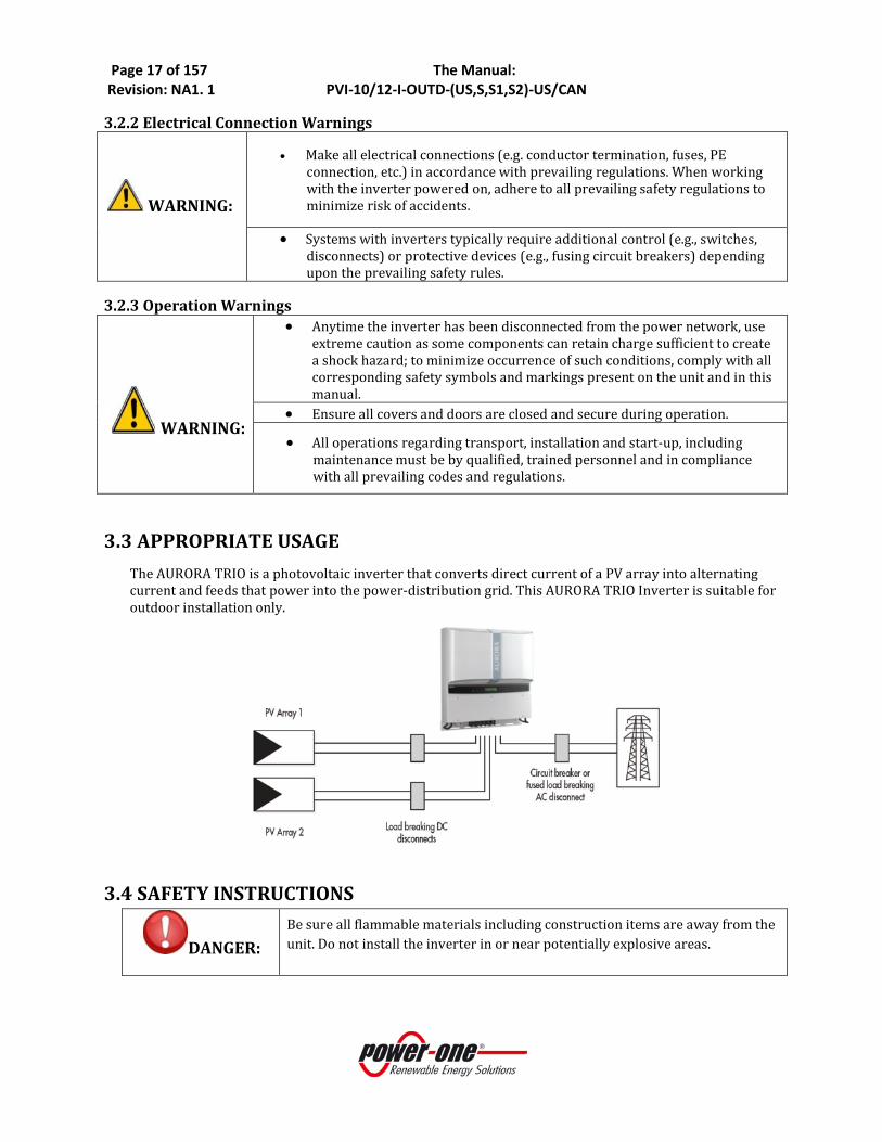
3.3 APPROPRIATE USAGE The AURORA TRIO is a photovoltaic inverter that converts direct current of a PV array into alternating current and feeds that power into the power-distribution grid. This AURORA TRIO Inverter is suitable for outdoor installation only.
3.4 SAFETY INSTRUCTIONS
DANGER: Be sure all flammable materials including construction items are away from the unit. Do not install the inverter in or near potentially explosive areas.

Page 18 of 157 The Manual: Revision: NA1. 1 PVI-10/12-I-OUTD-(US,S,S1,S2)-US/CAN
DANGER:
Normally grounded conductors may be ungrounded and energized when a ground-fault is indicated.
• Risk of electric shock
• Test before touching
• Work on the AURORA TRIO inverter must be carried out by qualified personnel.
WARNING:
Do not connect an AURORA TRIO Inverter to the electrical distribution grid until after receipt of a letter of authorization from the authority having jurisdiction.
WARNING:
Install the AURORA TRIO Inverter in accordance with the electrical standards prescribed by the applicable National Electric Code and/or by other local codes and regulations.
CAUTION:
The inverter weight is about 120lbs and is susceptible to tipping. It requires two or more persons to mount to bracket. Use proper lifting techniques to avoid personal injury.
CAUTION:
Cuts and scratches due to sharp edges inside the AURORA TRIO Inverter. Please use gloves and eye protection when working on this unit.
3.5 LOCATION OF SAFETY NOTICES Please note the location of safety notices on the AURORA TRIO Inverter for notification and protection. They are located on both side panels of this unit.

Page 19 of 157 The Manual: Revision: NA1. 1 PVI-10/12-I-OUTD-(US,S,S1,S2)-US/CAN
PART 2: UNPACK & SELECT INSTALL LOCATION
Page 20 of 157 The Manual: Revision: NA1. 1 PVI-10/12-I-OUTD-(US,S,S1,S2)-US/CAN
1.0 UNPACK AND INSPECT
WARNING
• Install the AURORA Inverter in accordance with the electrical standards prescribed by the applicable National Electric Code and/or by other local regulations and codes.
• Do not connect an AURORA Inverter to the electrical distribution grid until after receipt of a letter of authorization from the authority having jurisdiction.
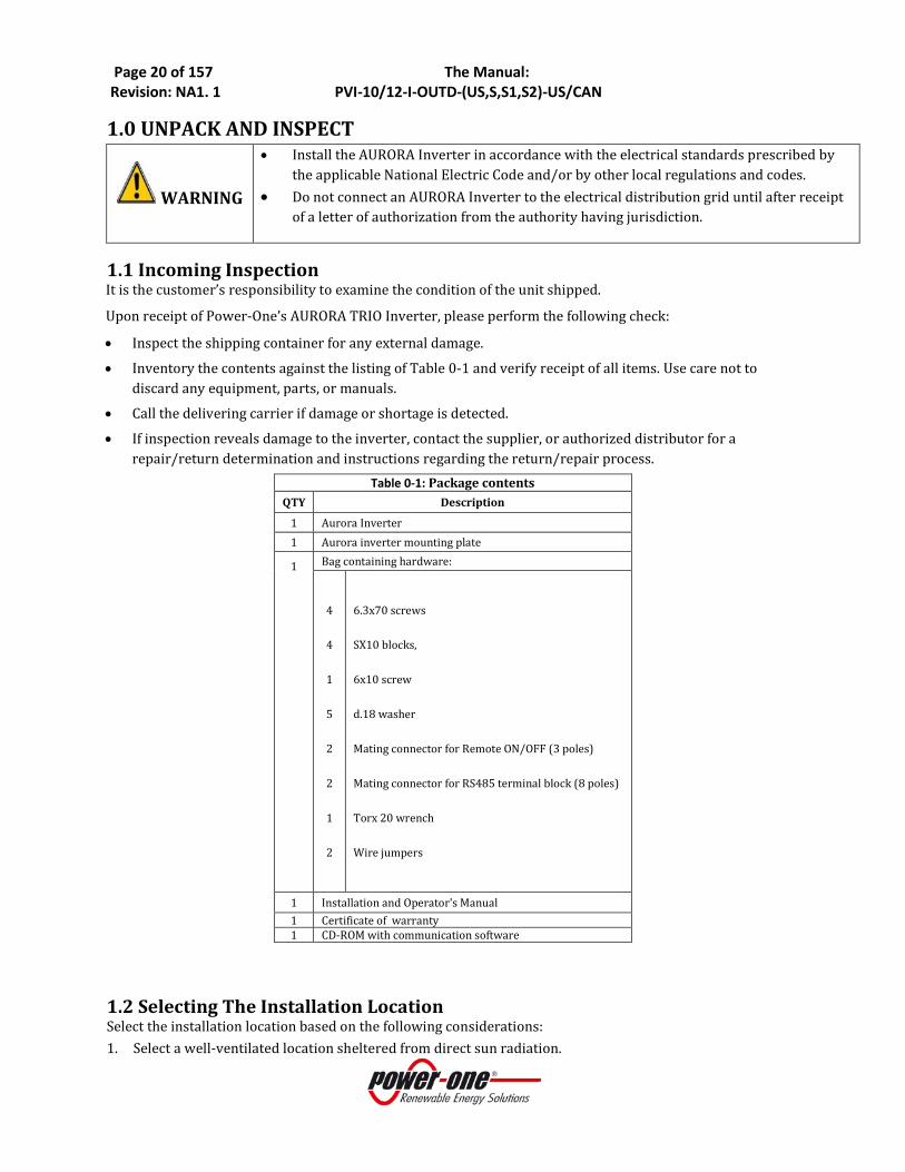
1.1 Incoming Inspection It is the customer’s responsibility to examine the condition of the unit shipped.
Upon receipt of Power-One’s AURORA TRIO Inverter, please perform the following check:
• Inspect the shipping container for any external damage.
• Inventory the contents against the listing of Table 0-1 and verify receipt of all items. Use care not to discard any equipment, parts, or manuals.
• Call the delivering carrier if damage or shortage is detected.
• If inspection reveals damage to the inverter, contact the supplier, or authorized distributor for a repair/return determination and instructions regarding the return/repair process.
Table 0-1: Package contents QTY Description
1 Aurora Inverter 1 Aurora inverter mounting plate
1
Bag containing hardware:
4
4
1
5
2
2
1
2
6.3x70 screws
SX10 blocks,
6x10 screw
d.18 washer
Mating connector for Remote ON/OFF (3 poles)
Mating connector for RS485 terminal block (8 poles)
Torx 20 wrench
Wire jumpers
1 Installation and Operator's Manual 1 Certificate of warranty 1 CD-ROM with communication software
1.2 Selecting The Installation Location Select the installation location based on the following considerations: 1. Select a well-ventilated location sheltered from direct sun radiation.

Page 21 of 157 The Manual: Revision: NA1. 1 PVI-10/12-I-OUTD-(US,S,S1,S2)-US/CAN
2. Choose a location that allows unobstructed airflow around the inverter. 3. Allow sufficient room around the inverter to enable easy installation and removal from the mounting
surface. 4. Height from ground level should be such that the display and status LEDs are easy to read. 5. Access panels on the front surface of the inverter allow inspection and maintenance of hardware; and
must not be blocked. Figure 0-1 shows the recommended minimum clearances around the inverter. 6. When possible, mount the AURORA TRIO Inverter vertically. For other mounting orientations consult
with Power-One.
7. Tilted mounting (±5° from vertical) is acceptable, but will reduce heat dissipation and may result in self-derating.
Figure 0-1 - Minimum Clearances around the AURORA Inverter
WARNING The inverter surface may become hot to the touch during operation. To avoid burn injury, DO NOT touch the inverter surface during operation.
Figure 0-2a Recommended Arrangement Figure 0-2b Unacceptable Arrangement
For installation of AURORA TRIO Inverter For installation of AURORA TRIO Inverter

Page 22 of 157 The Manual: Revision: NA1. 1 PVI-10/12-I-OUTD-(US,S,S1,S2)-US/CAN
NOTE
Do not mount the AURORA Inverter where exposed to direct sun radiation or any other heat source. This includes heat generated by other AURORA Inverters; otherwise, the inverter will self protect, resulting in derated power output. When the ambient temperature rises above 113°F/ 45°C the inverter may self-derate the output power. For full power of AURORA TRIO Inverter (no derating), be sure the airflow through the heat sink is clear. Blockages will result in less than expected power output.

Page 23 of 157 The Manual: Revision: NA1. 1 PVI-10/12-I-OUTD-(US,S,S1,S2)-US/CAN
PART 3: MOUNTING & WIRING Section 1:
PVI-10/12-I-OUTD-US/CAN-XXX
Section 2A:
PVI-10/12-I-OUTD-S-US/CAN-XXX (without fuse holders)
Section 2B:
PVI-10/12-I-OUTD-S1-US/CAN-XXX (with fuse holders)
Section 3A:
PVI-10/12-I-OUTD-S2-US/CAN-XXX (without fuse holders)
Section 3B:
PVI-10/12-I-OUTD-S2-US/CAN-XXX (with fuse holders)
Section 4:
WIRING DETAILS
Read and apply all safety warnings when performing these tasks.

Page 24 of 157 The Manual: Revision: NA1. 1 PVI-10/12-I-OUTD-(US,S,S1,S2)-US/CAN
SECTION 1: PVI-10/12-I-OUTD-US/CAN No Switchbox Version

Page 25 of 157 The Manual: Revision: NA1. 1 PVI-10/12-I-OUTD-(US,S,S1,S2)-US/CAN
1: 1.0 NAMEPLATE The nameplate shown above is affixed to the inverter and provides the following information:
5) Manufacturer code 6) Model code 7) Serial number 8) Week/Year of production
Sample product nameplate (PVI-10.0-I-OUTD-US-280-NG)
1: 2.0 UNIT MOUNTING PVI-10/12-I-OUTD-US/CAN-XXX-YY
Step 1: Locate and mark the desired surface mounting location.
Step 2: Orient the bracket such that the “C” hooks face outward and upward. See Figure 1:01a
Step 3: Using the hardware provided, level and mount bracket horizontally using mounting holes A and B in Figure 1:01a.
Step 4: Hang the inverter up on the mounted bracket by lifting the inverter over and above the mounting plate.
Carefully guide the inverter down into the bracket connecting the lip (Figure 1:01b, D) of the mating inverter bracket with the hooks C) on the bracket.
Make sure the connecting points in the bracket (C and D) and in the back of the inverter engage properly.
Step 5: Secure the bottom of the inverter using screw/washer through the hole marked H.
Page 26 of 157 The Manual: Revision: NA1. 1 PVI-10/12-I-OUTD-(US,S,S1,S2)-US/CAN
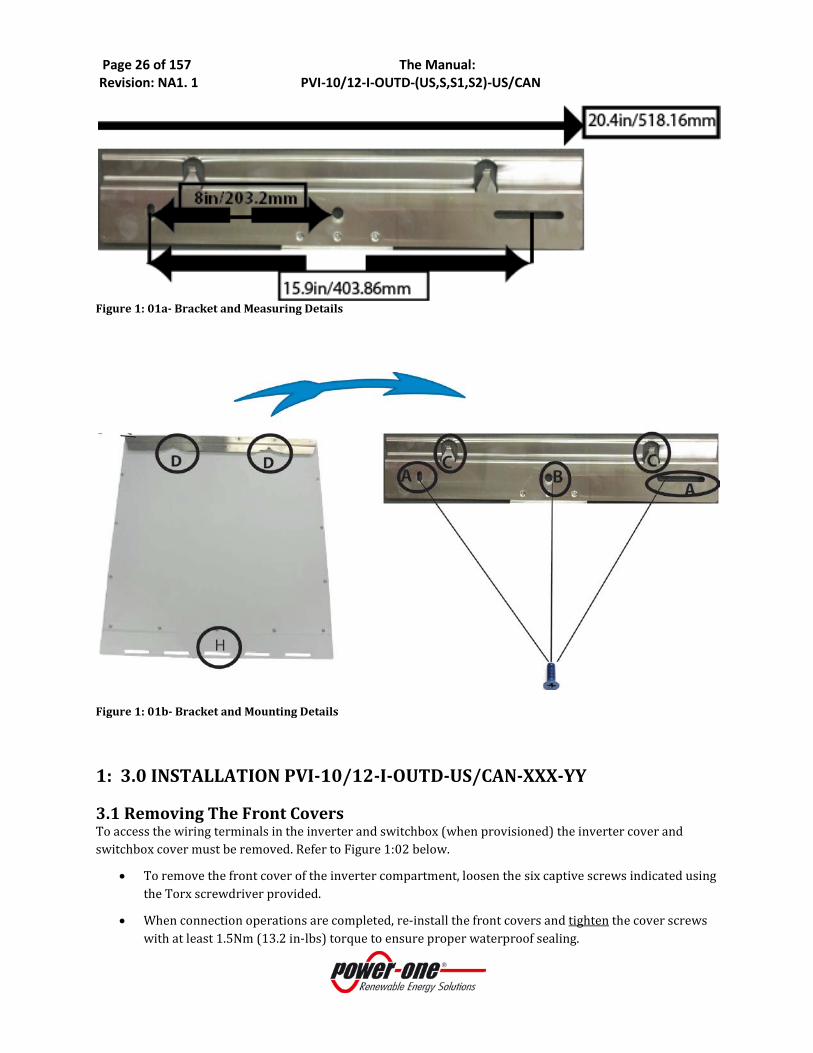
Figure 1: 01a- Bracket and Measuring Details
Figure 1: 01b- Bracket and Mounting Details
1: 3.0 INSTALLATION PVI-10/12-I-OUTD-US/CAN-XXX-YY
3.1 Removing The Front Covers To access the wiring terminals in the inverter and switchbox (when provisioned) the inverter cover and switchbox cover must be removed. Refer to Figure 1:02 below.
• To remove the front cover of the inverter compartment, loosen the six captive screws indicated using the Torx screwdriver provided.
• When connection operations are completed, re-install the front covers and tighten the cover screws with at least 1.5Nm (13.2 in-lbs) torque to ensure proper waterproof sealing.

Page 27 of 157 The Manual: Revision: NA1. 1 PVI-10/12-I-OUTD-(US,S,S1,S2)-US/CAN
Figure 1:02- Location of Front Access Panels
1: 3.2 Electrical Wiring and Connections PVI-10/12-I-OUTD-US/CAN-XXX-YY
DANGER
• This section is dedicated to initial installation wiring of the AURORA TRIO Inverter and assumes the unit has been physically mounted in its final location, but not yet wired.
• If the inverter has been previously wired and connected to the PV array and/or the AC grid, refer to Part 4: Operations & Start-Up for proper disconnect procedures.
3.2.1 Considerations Before Performing Electrical Connections This section provides a systematic description of correct wiring procedures. Please read the instructions provided and follow all safety warnings. Failure to comply with these instructions can result in safety hazards and may lead to possible injury to personnel and/or equipment damage.
WARNING
• Ensure wire sizing procedures are completed per appropriate local codes and regulations.
• Field wiring terminals are to be rated at 90°C/194°F. • Permanently mount the AURORA TRIO Inverter in its operational location prior to
beginning electrical connections. • Only qualified and properly trained personnel for the process of connecting the
AURORA Inverter to the electrical distribution grid, and only after receiving approval from the local authority having jurisdiction.
• Secure all signal wiring and cables to prevent contact with either AC grid and/or DC array field wiring; additionally, maintain spacing between the AC grid wiring and DC array wiring, secure as necessary.
• Do not under any circumstances exceed the maximum ratings of voltage and current when designing the system, to include: o Do not exceed the maximum array DC voltage input to each MPPT circuit of
520 Vdc under any condition. o Do not exceed the maximum array DC current input of 24 Adc (10kW) or
25Adc (12kW) to each MPPT circuit. o See data sheet in Part 7 for more details.
• An automatic over-current device (e.g., circuit breaker) must be used between the AURORA Inverter and the distribution grid.
Inverter cover: Torx 20, Screw, 6pl
Captive screws X6

Page 28 of 157 The Manual: Revision: NA1. 1 PVI-10/12-I-OUTD-(US,S,S1,S2)-US/CAN
3.2.2 Field Wiring –Knockout Details PVI-10/12-I-OUTD-US/CAN-XXX-YY
Code Location
Description Code Location
Description
A DC Power Cable Knockouts; 1”, ¾“trade size.
D Signal Cable Knockouts; ½” trade size
B AC Power Cables Knockouts 1”, ¾” trade size
E GFD Fuse Holder
C Ground Cable Knockouts;1/2” trade size
Figure 1:03 Chassis Layout
In this version of AURORA TRIO Inverter, DC array wiring and AC grid wiring (with required switching and Over Current Protection Device (OCPD) are connected directly to the inverter terminals without benefit of integral disconnect switches.
WARNING
• It is the responsibility of the installer to provide external disconnect switches and Over Voltage Current Devices (OCPD) as required by National Electric Codes and other prevailing regulations.
• Use care when accessing the DC array and AC grid wiring and associated terminals as this version has no integrated disconnects switches. Hazardous voltage is present unless the user provided external disconnect switches are turned OFF and locked out. External disconnect switches for both the AC and DC connections are mandated by electrical codes.

Page 29 of 157 The Manual: Revision: NA1. 1 PVI-10/12-I-OUTD-(US,S,S1,S2)-US/CAN
Location
Indicator Details Location
Indicator Details
A Grid Selector/Country Code – thumbwheel switches
04 H MPPT Input Selector Switch
Choose PAR or IND MPPT Operation
B DC Array: MPPT 1 input Note 1 below J Alarm Out Terminals for External Alarm Note 3 below
C DC Array: MPPT2 input Note 1 below K RS485 Bus Connection Via RJ485 Connector Use with CAT5 Cable
D Main PE Ground Terminal Note 1 below L RS485 Bus Connection
Via Screw Terminals Note 3 below
E 3 ø AC Grid Output Terminals Note 2
below M RS485 Termination
Switch See Signal Connection Section for more detail
F 3 ø AC Grid Neutral Terminal for 4W Grid Connection
Note 2
below N Remote ON/OFF
screw terminals See Signal Connection Section for more detail
G 3PHMOD Switch
3ø Mode Selector
Choose 3W or 4W Grid Connection
O GFD Fuse
Notes: 1. Terminals accept wire range of #12-#4AWG (Refer to local code for appropriate wire size); torque to 13in-lb.
2. Terminals accept wire range of #12-#4AWG (Refer to local code for appropriate wire size); torque to 13in-lb.
3. Mating terminal in hardware kit. Terminals accept wire size range up to #16 AWG; torque to 8in-lb. Figure 1:04 Wiring Connection Details for PVI-10/12-I-OUTD-US/CAN-XXX

Page 30 of 157 The Manual: Revision: NA1. 1 PVI-10/12-I-OUTD-(US,S,S1,S2)-US/CAN
3.2.3 INITIAL ELECTRICAL CONNECTIONS PVI-10/12-I-OUTD-US/CAN-XXX-NG
DANGER If the unit has been previously wired and energized, refer to Section 4: Operations for appropriate disconnection procedures.
This section describes initial installation procedures for DC and AC wiring connections to the PVI-10/12-I-OUTD-US/CAN-XXX inverter version, which has no integral, disconnect switches or associated switchbox.
• Typical system connections for this inverter are shown in Figure 1:05. • Relevant wiring connections are shown in Figure 1:03 and Figure 1:04.
This version requires the installer to provide the following items:
1. DC disconnect switch: 2-pole, 600V rated. Current rating is based on the model chosen - refer to technical notes in Part 7: The Appendix. The switch must have two independent sections to accommodate the dual MPPT capability.
2. AC disconnect switch: 3-pole, with or without neutral block depending upon chosen grid connection (3W or 4W). Voltage and current rating depends on the grid connection voltage and output power of the inverter being installed.
3. Over-Current Protection Device: fusing or circuit breaker - between inverter and grid. Circuit breaker must be rated for bidirectional current flow. Rating of OCPD is dependent on specific grid connection - see product nameplate in Figure 1:01.
Figure 1: 05 Electrical Connection Diagram PVI-10/12-I-OUTD-US-XXX-NG
1. Refer to Figure 06 and locate the designated entry locations for the conduits from the DC array and to the AC grid.
2. Verify that the appropriate knock-outs have been employed for the use specified to maintain spacing between wiring groups.
Page 31 of 157 The Manual: Revision: NA1. 1 PVI-10/12-I-OUTD-(US,S,S1,S2)-US/CAN
3.2.4 DC ARRAY CONNECTIONS PVI-10/12-I-OUTD-US/CAN-XXX-NG
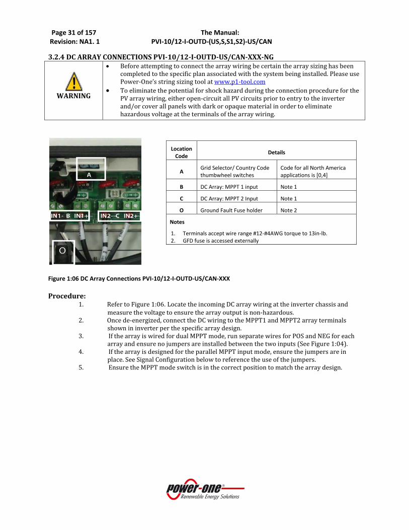
WARNING
• Before attempting to connect the array wiring be certain the array sizing has been completed to the specific plan associated with the system being installed. Please use Power-One’s string sizing tool at www.p1-tool.com
• To eliminate the potential for shock hazard during the connection procedure for the PV array wiring, either open-circuit all PV circuits prior to entry to the inverter and/or cover all panels with dark or opaque material in order to eliminate hazardous voltage at the terminals of the array wiring.
Figure 1:06 DC Array Connections PVI-10/12-I-OUTD-US/CAN-XXX Procedure:
1. Refer to Figure 1:06. Locate the incoming DC array wiring at the inverter chassis and measure the voltage to ensure the array output is non-hazardous.
2. Once de-energized, connect the DC wiring to the MPPT1 and MPPT2 array terminals shown in inverter per the specific array design.
3. If the array is wired for dual MPPT mode, run separate wires for POS and NEG for each array and ensure no jumpers are installed between the two inputs (See Figure 1:04).
4. If the array is designed for the parallel MPPT input mode, ensure the jumpers are in place. See Signal Configuration below to reference the use of the jumpers.
5. Ensure the MPPT mode switch is in the correct position to match the array design.
Location Code Details
A Grid Selector/ Country Code thumbwheel switches
Code for all North America applications is [0,4]
B DC Array: MPPT 1 input Note 1
C DC Array: MPPT 2 Input Note 1
O Ground Fault Fuse holder Note 2
Notes
1. Terminals accept wire range #12-#4AWG torque to 13in-lb. 2. GFD fuse is accessed externally
Page 32 of 157 The Manual: Revision: NA1. 1 PVI-10/12-I-OUTD-(US,S,S1,S2)-US/CAN
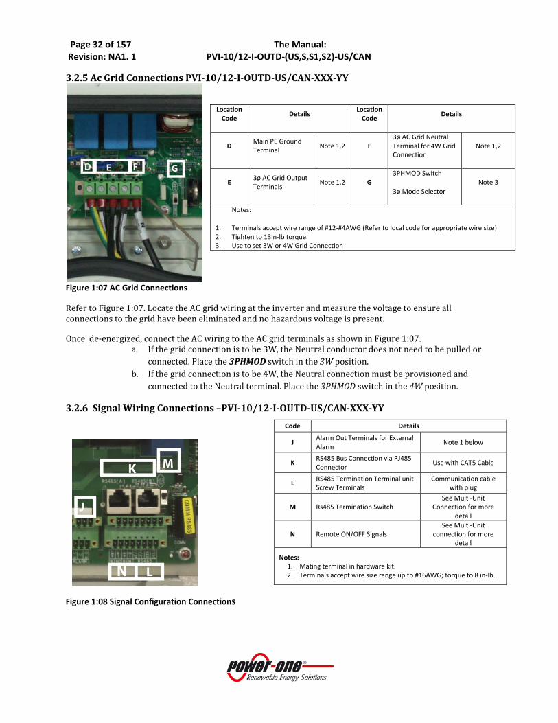
3.2.5 Ac Grid Connections PVI-10/12-I-OUTD-US/CAN-XXX-YY
Figure 1:07 AC Grid Connections
Refer to Figure 1:07. Locate the AC grid wiring at the inverter and measure the voltage to ensure all connections to the grid have been eliminated and no hazardous voltage is present.
Once de-energized, connect the AC wiring to the AC grid terminals as shown in Figure 1:07. a. If the grid connection is to be 3W, the Neutral conductor does not need to be pulled or
connected. Place the 3PHMOD switch in the 3W position. b. If the grid connection is to be 4W, the Neutral connection must be provisioned and
connected to the Neutral terminal. Place the 3PHMOD switch in the 4W position.
3.2.6 Signal Wiring Connections –PVI-10/12-I-OUTD-US/CAN-XXX-YY
Figure 1:08 Signal Configuration Connections
Location Code Details Location
Code Details
D Main PE Ground Terminal Note 1,2 F
3ø AC Grid Neutral Terminal for 4W Grid Connection
Note 1,2
E 3ø AC Grid Output Terminals Note 1,2 G
3PHMOD Switch
3ø Mode Selector Note 3
Notes:
1. Terminals accept wire range of #12-#4AWG (Refer to local code for appropriate wire size) 2. Tighten to 13in-lb torque. 3. Use to set 3W or 4W Grid Connection
Code Details
J Alarm Out Terminals for External Alarm Note 1 below
K RS485 Bus Connection via RJ485 Connector Use with CAT5 Cable
L RS485 Termination Terminal unit Screw Terminals
Communication cable with plug
M Rs485 Termination Switch See Multi-Unit
Connection for more detail
N Remote ON/OFF Signals See Multi-Unit
connection for more detail
Notes: 1. Mating terminal in hardware kit. 2. Terminals accept wire size range up to #16AWG; torque to 8 in-lb.

Page 33 of 157 The Manual: Revision: NA1. 1 PVI-10/12-I-OUTD-(US,S,S1,S2)-US/CAN
• Route the cables through the inverter chassis refer to Figure 1:03. • Refer to Figure 1:03 and note the position where the monitoring and alarm cables (if used)
enter the chassis. • Refer to Figure 1:08.Locate the terminals for the alarm and monitoring connections within
the chassis. • Connect alarm cable to the mating connector (in hardware kit) and plug connector into
position shown in Figure 1:09.
3.2.6.1 Connect RS485 Monitoring Cable a. If using CAT5 cable for monitoring connections, connect RJ45 plug to the end of the cable
as shown in Table 3a and plug into RJ45 jack. A second jack is in parallel to accommodate daisy chaining of communication line to other inverters. See Multi-System Connections below for more information.
b. If running standard cable locate the mating connector (hardware bag) and connect three RS-485 leads as shown in Figure 1:09. Plug connector into position shown; second connector is to facilitate daisy chaining.
Table 3a: RJ45 Connectors
Figure 1:09: Standard RS 485 Connection
S2 switch

Page 34 of 157 The Manual: Revision: NA1. 1 PVI-10/12-I-OUTD-(US,S,S1,S2)-US/CAN
1: 3.3 CONFIGURATION PVI-10/12-I-OUTD-US/CAN-XXX-NG
POSSIBLE AURORA INVERTER DC INPUT CONFIGURATION The Aurora inverter is configurable with an independent MPPT for each DC input channel or the two input DC channels maybe connected in parallel and operated with one MPPT. If the inverter is configured with independent MPPTs, the max current for each channel shall not exceed 24 Adc (10kW) or 25Adc (12kW) and the power input for a single channel shall not exceed 6.8 kW.
Figure 1:10- Configuration Settings COUNTRY CODE SELECTOR 3PHMOD SWITCH PAR/IND INMODE SWITCH
1:
3W-Δ
4W-Y
3:
PAR
IND
2:
Page 35 of 157 The Manual: Revision: NA1. 1 PVI-10/12-I-OUTD-(US,S,S1,S2)-US/CAN
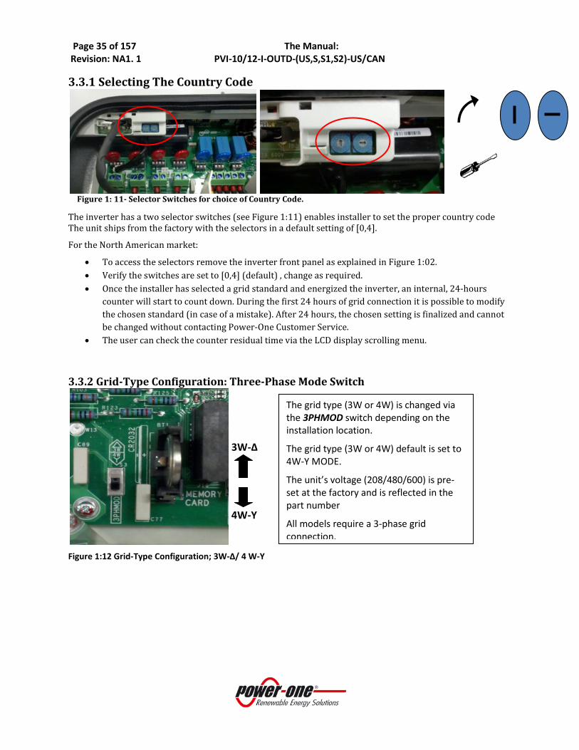
3.3.1 Selecting The Country Code
Figure 1: 11- Selector Switches for choice of Country Code.
The inverter has a two selector switches (see Figure 1:11) enables installer to set the proper country code The unit ships from the factory with the selectors in a default setting of [0,4].
For the North American market:
• To access the selectors remove the inverter front panel as explained in Figure 1:02. • Verify the switches are set to [0,4] (default) , change as required. • Once the installer has selected a grid standard and energized the inverter, an internal, 24-hours
counter will start to count down. During the first 24 hours of grid connection it is possible to modify the chosen standard (in case of a mistake). After 24 hours, the chosen setting is finalized and cannot be changed without contacting Power-One Customer Service.
• The user can check the counter residual time via the LCD display scrolling menu.
3.3.2 Grid-Type Configuration: Three-Phase Mode Switch
Figure 1:12 Grid-Type Configuration; 3W-Δ/ 4 W-Y
3W-Δ
4W-Y
The grid type (3W or 4W) is changed via the 3PHMOD switch depending on the installation location.
The grid type (3W or 4W) default is set to 4W-Y MODE.
The unit’s voltage (208/480/600) is pre-set at the factory and is reflected in the part number
All models require a 3-phase grid connection.

Page 36 of 157 The Manual: Revision: NA1. 1 PVI-10/12-I-OUTD-(US,S,S1,S2)-US/CAN
3.3.3 Independent or Parallel Connection Aurora inverters have dual inputs with independent MPPT circuits. The inverter when operated in the dual input mode can optimize two independent arrays. The inverter can also be operated in a single MPPT mode from a single array by connecting the inputs in parallel using jumpers and proper setting of the INMODE switch (see figure 1.10, above). The following sections show how to connect the inverter in either the INDependent or PARallel mode.
3.3.3.1 Independent Connection For applications where the two MPPT channels will be used independently:
• Place switch “S1” (shown in Figure 1:13) in the “IND” (default position) position to configure the inverter controls in the independent mode.
• Make sure the parallel jumpers, as shown in Figure 14b are not installed. The parallel jumpers are not needed when inverter is set in independent (IND) mode. Do not install parallel jumpers in IND configuration. If they are installed, remove them.
• After switching the AURORA TRIO Inverter to independent mode configuration, re-install the front panel (apply 13.2 in-lbs of torque to each of the 4 screws).
• This unit is default set to the independent mode: IND
Figure 1:13: INMODE switch set to IND mode
3.3.3.2 Parallel Connection To operate the inverter in the single MPPT mode:
• Place switch “INMODE” (shown in Figure 14a) in the “PAR” in order to configure the inverter controls in parallel mode.
• Parallel the two MPPT inputs using terminal [–IN1 and –IN2] and [+IN1 and
+IN2] as shown in Figure 14b using two #10 AWG jumper wires (1 black and 1 red cable) to connect the input.
• After switching the AURORA TRIO Inverter to parallel mode configuration, re-install the front panel (apply 13.2 in-lbs of torque to each of the 4 screws).
IND

Page 37 of 157 The Manual: Revision: NA1. 1 PVI-10/12-I-OUTD-(US,S,S1,S2)-US/CAN
Figure 14a: INMODE switch set to PAR mode
WARNING Before selecting the grid standard on the unit check the utility connectionis the necessary standard.
PAR
Figure 14b: Add Jumpers for Parallel MPPT Input Configuration
Page 38 of 157 The Manual: Revision: NA1. 1 PVI-10/12-I-OUTD-(US,S,S1,S2)-US/CAN
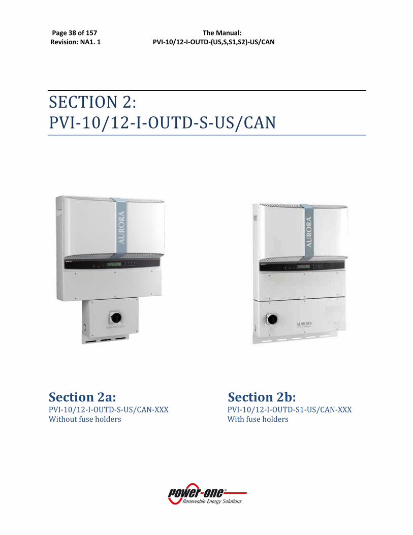
SECTION 2: PVI-10/12-I-OUTD-S-US/CAN
Section 2a: Section 2b: PVI-10/12-I-OUTD-S-US/CAN-XXX PVI-10/12-I-OUTD-S1-US/CAN-XXX Without fuse holders With fuse holders

Page 39 of 157 The Manual: Revision: NA1. 1 PVI-10/12-I-OUTD-(US,S,S1,S2)-US/CAN
SECTION 2a: PVI-10/12-I-OUTD-S-US/CAN* Without fuse holders *The PVI-10/12-I-OUTD-S-US/CAN will be replaced by the PVI-10/12-I-OUTD-S1-US/CAN in 2012.

Page 40 of 157 The Manual: Revision: NA1. 1 PVI-10/12-I-OUTD-(US,S,S1,S2)-US/CAN
2a: 1.0 NAMEPLATE The nameplate shown above is affixed to the inverter and provides the following information:
9) Manufacturer code 10) Model code 11) Serial number 12) Week/Year of production
Sample product nameplate (PVI-10.0-I-OUTD-S-US-480-NG-12A)
2a: 2.0 MOUNTING PVI-10/12-I-OUTD-S-US/CAN-XXX-YY

Page 41 of 157 The Manual: Revision: NA1. 1 PVI-10/12-I-OUTD-(US,S,S1,S2)-US/CAN
Figure 2:01 Bracket and Mounting Details Step 1: Locate and mark the desired mounting location as shown above in mounting location. Step 2: Orient the bracket such that the “C” hooks face outward and upward. (Figure.2:01) Step 3: Using the hardware provided, level and mount the bracket to the surface using mounting holes shown in Figure 2:01. Step 4: Hang the inverter on the mounted bracket by lifting the unit up over and above the mounting plate. Carefully guide the inverter and switchbox brackets and in the back of the inverter engage properly. Step 5: Secure the bottom of the inverter using the machine screw (6x20mm) and washer (18mm diameter) provided. Insert machine screw through center hole of the bottom inverter mount, and engage the PEMnut mounted in the bracket. (H, in Figure 2:01)
2a: 3.0 INSTALLATION PVI-10/12-I-OUTD-S-US/CAN-XXX-YY
3.1 Removing The Front Covers To access the wiring terminals in the inverter and switchbox (when provisioned) the inverter cover and switchbox cover must be removed. Refer to Figure 2:02
• To remove the front cover of the inverter compartment, loosen the six captive screws indicated using the Torx screwdriver provided.
• To remove the front cover of the switchbox Figure 2:02, loosen the six captive screws indicated using the Torx screwdriver provided in the box with the inverter.
• When connection operations are completed, re-install the front covers and tighten the cover screws with at least 1.5Nm (13.2 in-lbs) torque to ensure proper waterproof sealing.
C C
D
H
D
C
D
H

Page 42 of 157 The Manual: Revision: NA1. 1 PVI-10/12-I-OUTD-(US,S,S1,S2)-US/CAN
Switchbox cover
Torx 20 screw, 4pl
Inverter coverTorx 20 screw, 6pl
Figure 2:02- Location of Front Access Panels
3.2 Electrical Wiring and Connections PVI-10/12-I-OUTD-S-US/CAN-XXX-YY
DANGER
• This section is dedicated to initial installation wiring of the AURORA TRIO Inverter and assumes the unit has been physically mounted in its final location, but not yet wired.
• If the inverter has been previously wired and connected to the PV array and/or the AC grid, refer to Part 4: Operations for disconnection procedures.
3.2.1 Considerations Before Performing Electrical Connections This section provides a systematic description of correct wiring procedures.
Please read the instructions provided and follow all safety warnings.
WARNING Failure to comply with these instructions can result in safety hazards and may lead to possible injury to personnel and/or equipment damage.
3.2.2 Field Wiring-Knockout- Details PVI-10/12-I-OUTD-S-US/CAN-XXX-YY To access the wiring components inside the switchbox shown in Figure 2:04, loosen the four cover panel captive screws shown in Figure 2:02, and remove the cover panel.
Page 43 of 157 The Manual: Revision: NA1. 1 PVI-10/12-I-OUTD-(US,S,S1,S2)-US/CAN
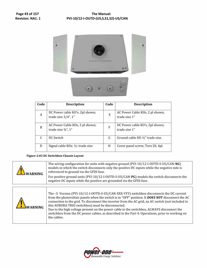
Code Description Code Description
A DC Power cable KO’s, 2pl shown; trade size 3/4”, 1”
E AC Power Cable KOs, 2 pl shown; trade size 1”
B AC Power Cable KOs, 2 pl shown; trade size ¾”, 1”
F DC Power cable KO’s, 2pl shown; trade size 1”
C DC Switch G Ground cable KO ½” trade size.
D Signal cable KOs: ½: trade size H Cover panel screw, Torx 20, 4pl.
Figure 2:03 DC Switchbox Chassis Layout
WARNING
The wiring configuration for units with negative ground (PVI-10/12-I-OUTD-S-US/CAN-NG) models in which the switch disconnects only the positive DC inputs while the negative side is referenced to ground via the GFDI fuse. For positive ground units (PVI-10/12-I-OUTD-S-US/CAN-PG) models the switch disconnects the negative DC inputs while the positive are grounded via the GFDI fuse.
WARNING
The –S Version (PVI-10/12-I-OUTD-S-US/CAN-XXX-YYY) switchbox disconnects the DC current from the photovoltaic panels when the switch is in “OFF” position. It DOES NOT disconnect the AC connection to the grid. To disconnect the inverter from the AC grid, an AC switch (not included in this AURORA TRIO switchbox) must be disconnected. Due to the high voltage present on the power cable in the switchbox, ALWAYS disconnect the switchbox from the DC power cables, as described in the Part 4: Operations, prior to working on the cables.
A B
C
H
F G E D
Page 44 of 157 The Manual: Revision: NA1. 1 PVI-10/12-I-OUTD-(US,S,S1,S2)-US/CAN
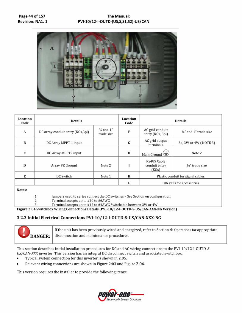
Location Code Details Location
Code Details
A DC array conduit entry (KOs,3pl) ¾ and 1” trade size F AC grid conduit
entry (KOs, 3pl) ¾” and 1” trade size
B DC Array MPPT 1 input G AC grid output terminals 3ø, 3W or 4W ( NOTE 3)
C DC Array MPPT2 input H Main Ground Note 2
D Array PE Ground Note 2 J RS485 Cable conduit entry
(KOs) ½” trade size
E DC Switch Note 1 K Plastic conduit for signal cables
L DIN rails for accessories
Notes:
1. Jumpers used to series connect the DC switches – See Section on configuration. 2. Terminal accepts up to #20 to #6AWG 3. Terminal accepts up to #12 to #4AWG Switchable between 3W or 4W
Figure 2:04 Switchbox Wiring Connections Details (PVI-10/12-I-OUTD-S-US/CAN-XXX-NG Version)
3.2.3 Initial Electrical Connections PVI-10/12-I-OUTD-S-US/CAN-XXX-NG
DANGER: If the unit has been previously wired and energized, refer to Section 4: Operations for appropriate disconnection and maintenance procedures.
This section describes initial installation procedures for DC and AC wiring connections to the PVI-10/12-I-OUTD-S-US/CAN-XXX inverter. This version has an integral DC disconnect switch and associated switchbox. • Typical system connection for this inverter is shown in 2:05. • Relevant wiring connections are shown in Figure 2:03 and Figure 2:04.
This version requires the installer to provide the following items:

Page 45 of 157 The Manual: Revision: NA1. 1 PVI-10/12-I-OUTD-(US,S,S1,S2)-US/CAN
1. AC disconnect switch. 3-phase, with or without Neutral block depending upon chosen grid connection (3W or 4W). Voltage and current rating depends on the grid connection voltage and output power of the inverter being installed.
2. Over-Current Protection Device (OCPD) - fusing or circuit breaker - between inverter and grid. Circuit breaker must be rated for bidirectional current flow. Rating of OCPD is dependent on specific grid connection - see nameplate in Section 2:1.0.
Figure 2:05: Electrical Connection Diagram PVI-10/12-I-OUTD-S-US/CAN-XXX-NG
1. Refer to the photo of Figure 2:03 and locate the designated entry locations for the conduits from the DC array and to the AC grid.
2. Make sure the appropriate knockouts are employed for the use specified in order to maintain required spacing between wiring groups.
3.2.4 Dc Array Connections
WARNING:
• Before attempting to connect the array wiring be certain the array sizing has been completed to the specific plan associated with the system being installed.
• To eliminate the potential for shock hazard during the connection procedure for the PV array wiring, either open-circuit all PV circuits prior to entry to the inverter and/or cover all panels with dark or opaque material in order to eliminate hazardous voltage at the terminals of the array wiring.

Page 46 of 157 The Manual: Revision: NA1. 1 PVI-10/12-I-OUTD-(US,S,S1,S2)-US/CAN
Figure 2:06- DC Array Wiring PVI-10/12-I-OUTD-S-US/CAN-XXX-NG
• Refer to Figure 2:06. Locate the incoming DC array wiring at the inverter chassis. Measure the voltage to ensure the array output is non-hazardous.
• Once de-energized, connect the DC wiring to the MPPT1 and MPPT2 array terminals shown in inverter per the specific array design.
• If the array is wired for dual MPPT mode, run separate wires for POS and NEG for each array and ensure no jumpers are installed between the two inputs. See signaling section for more details.
• If the array is designed for the parallel MPPT input mode, ensure the jumpers shown in place. See signaling section for more details.
• Ensure the MPPT-mode switch is in the correct position to match the array design.
3.2.5 AC Grid Connections
Figure 2:07-AC Grid Connection
• Locate the AC grid wiring at the inverter switchbox. Measure the voltage to ensure all connections to the
grid have been eliminated and no hazardous voltage is present.
Details
A DC array conduit entry (KOs,3pl) ¾ and 1” trade size
B DC Array MPPT 1 input Note 1
C DC Array MPPT2 input
D Array PE Ground Note 2
E DC Switch Note 3
Notes:
1 Terminal accepts up to ##20 to #6AWG
2. Terminal accepts up to #4AWG.
3. Jumpers used to series connect the DC switch segments for 600V operation.
Code Details
F AC grid conduit entry (KOs, 3pl) ¾” and 1” trade size
G AC grid output terminals Note 1,2
H Main Ground Note 1
Notes: 1. Terminal accepts up to #4AWG 2. 3W or 4W via 3PHMOD switch setting.

Page 47 of 157 The Manual: Revision: NA1. 1 PVI-10/12-I-OUTD-(US,S,S1,S2)-US/CAN
• Once de-energized, connect the AC wiring to the AC grid terminals as shown in 2:07. a. If the grid connection is to be 3W, the Neutral conductor does not need not be pulled or connected.
Place the 3PHMOD switch in the 3W position b. If the grid connection is to be 4W, the Neutral connection must be provisioned and connected to the
Neutral terminal. Place the 3PHMOD switch in the 4W position.
3.2.6 Signal Wiring Connections
Figure 2:08 Signal Wire Routing
• Route the cables through the switchbox and into the inverter chassis using plastic guide (item K, Figure 2:08.
• Refer to Figure 2:03, and note the position where the monitoring and alarm cables (if used) enter the chassis.
• Refer to Figure 2:03. Locate the terminals for the alarm and monitoring connections within the chassis • Connect alarm cable to the mating connector (in hardware kit) and plug connector into position shown in
Figure 2:09.
3.2.6.1 Connect RS485 Monitoring Cable
Table 3: RJ45 Connectors
Code Details
F AC grid conduit entry (KOs, 3pl) ¾” and 1” trade size
G AC grid output terminals 3Ø, 3W or /4W
J RS485 Cable conduit entry (KOs) ½” trade size
K Plastic conduit for signal cables
L DIN rails for accessories
Page 48 of 157 The Manual: Revision: NA1. 1 PVI-10/12-I-OUTD-(US,S,S1,S2)-US/CAN
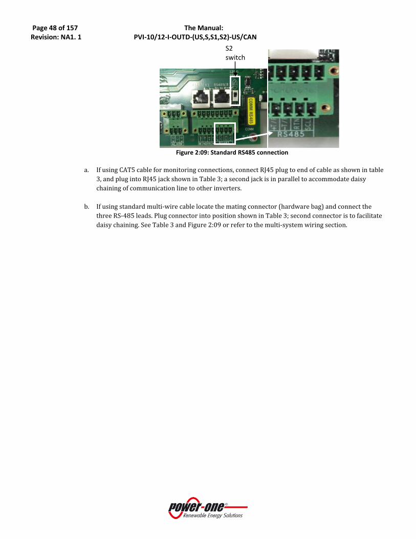
Figure 2:09: Standard RS485 connection
a. If using CAT5 cable for monitoring connections, connect RJ45 plug to end of cable as shown in table
3, and plug into RJ45 jack shown in Table 3; a second jack is in parallel to accommodate daisy chaining of communication line to other inverters.
b. If using standard multi-wire cable locate the mating connector (hardware bag) and connect the three RS-485 leads. Plug connector into position shown in Table 3; second connector is to facilitate daisy chaining. See Table 3 and Figure 2:09 or refer to the multi-system wiring section.
S2 switch

Page 49 of 157 The Manual: Revision: NA1. 1 PVI-10/12-I-OUTD-(US,S,S1,S2)-US/CAN
2a: 3.3 DC INPUT CONFIGURATION PVI-10/12-I-OUTD-S-US/CAN-XXX-NG The Aurora inverter is configurable with an independent MPPT for each DC input channel or with the two input DC channels connected in parallel with one MPPT. If the inverter is configured with two independent MPPTs, the max current for each channel shall not exceed 24 Adc (10kW)/ 25Adc (12kW) and the power input for the single channel shall not exceed 6.8 kW.
Figure 2:10: Configuration Settings
COUNTRY CODE SELECTOR 3PHMOD SWITCH PAR/IND INMODE SWITCH
3.3.1 SELECTING THE COUNTRY CODE
Figure 2:11- Selector Switches for Choice of Country Code.
1:
3W-Δ
4W-Y
3:
PAR
IND
2:

Page 50 of 157 The Manual: Revision: NA1. 1 PVI-10/12-I-OUTD-(US,S,S1,S2)-US/CAN
The inverter has two selector switches. (see Figure 2:11) These enable installers to set the proper grid standard for the North American versions. The factory default setting is [0,4].
For the North American market:
3. To access the selector switches remove the inverter front panel as explained in Figure 2:02
4. Ensure the switches are set to [0,4], change if necessary.
WARNING:
Once the installer has selected a grid standard and energized the inverter, an internal, 24 hour counter will start to count down. During the first 24 hours of grid connection it is possible to modify the chosen standard (in case of mistakes). After 24 hours, the chosen setting is finalized and cannot be changed without contacting Power-One Customer Service. User can check the counter residual time via the LCD scrolling menu.
WARNING Before selecting the inverter grid standard on the, accurately identify the required utility grid standard.
3.3.2 Grid-Type Configuration:Three-Phase Connection Selection:
Figure 2:12: Phase configuration; 3W-Δ/ 4W- Y
3.3.3 Independent Or Parallel Connection of Dual Inputs The Aurora inverters have dual inputs with independent MPPT circuits. The inverter when operated in the dual input mode can optimize two independent arrays. The inverter can also be operated in a single MPPT mode from a single array by connecting the inputs in parallel using jumpers and proper setting of the INMODE switch (see figure 2.10, above. The following sections show how to connect the inverter in either the INDependent or PARallel mode.
3W-Δ
4W-Y
The grid type (3W or 4W) is changed via the 3-phase mode switch depending on the installation location.
The grid type (3W or 4W) default is set to 4W-Y MODE.
The unit’s voltage (208/480/600) is pre-set at the factory and is reflected in the part number
All models require a 3-phase grid connection.

Page 51 of 157 The Manual: Revision: NA1. 1 PVI-10/12-I-OUTD-(US,S,S1,S2)-US/CAN
3.3.3.1 Independent Connection For applications where the two MPPT channels will be used independently:
• Place switch “INMODE” (shown in Figure 2:13) in the “IND” (default position) position to configure the inverter controls in the independent mode.
• Ensure the parallel jumper wiring (see Figure
2:14b), is not present.
• After switching the AURORA TRIO Inverter to independent mode configuration, re-install the front panel (apply 13.2 in-lbs of torque to each of the 4 screws).
Figure 2:13: Independent MPPT Configuration Switch
3.3.3.2 Parallel Connection To operate the inverter in the single MPPT mode:
• Place switch S1 (shown in Figure 2:14a) in the “PAR” in order to configure the inverter controls in parallel mode.
• Parallel the two MPPT inputs using terminal [–IN1 and –IN2] and [+IN1 and +IN2] as shown in Figure 2:14b using two#10 AWG jumper wires (1 black and 1 red cable) to connect the input.
• After switching the AURORA TRIO Inverter to parallel mode configuration, re-install the front panel (apply 13.2 in-lbs of torque to each of the 4 screws).
Figure 2:14a: Parallel MPPT Configuration Switch
IND
PAR
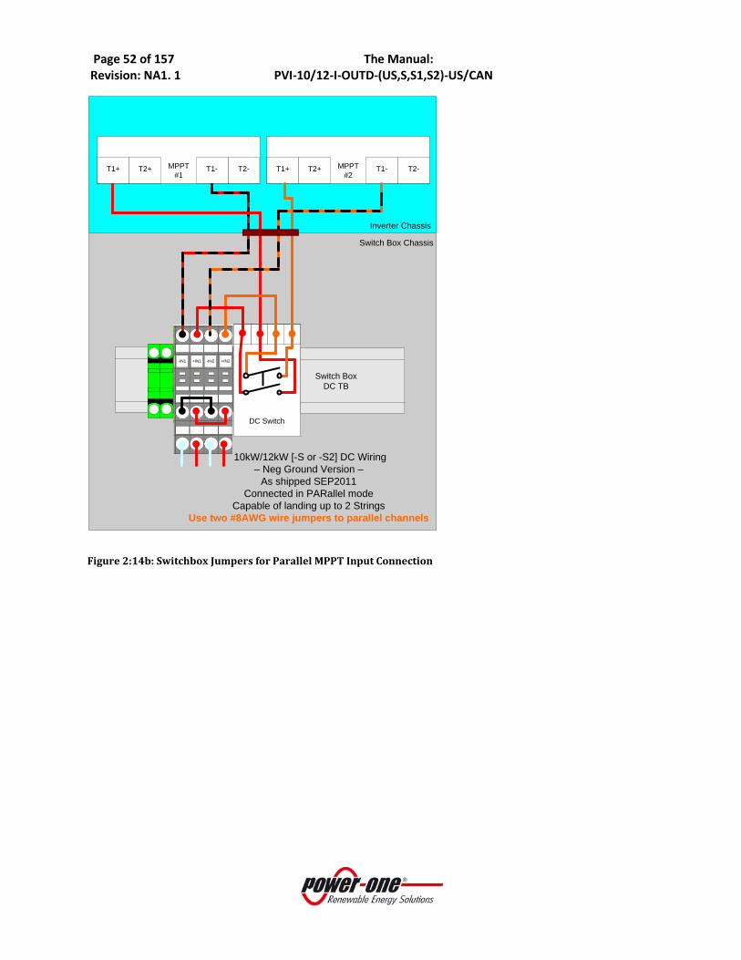
Page 52 of 157 The Manual: Revision: NA1. 1 PVI-10/12-I-OUTD-(US,S,S1,S2)-US/CAN
MPPT#1
T1+ T2+ T2-
Switch Box Chassis
T1- MPPT#2
T1+ T2+ T2- T1-
Inverter Chassis
+IN1-IN1 -IN2 +IN2
Switch BoxDC TB
DC Switch
10kW/12kW [-S or -S2] DC Wiring– Neg Ground Version –
As shipped SEP2011Connected in PARallel mode
Capable of landing up to 2 Strings Use two #8AWG wire jumpers to parallel channels
Figure 2:14b: Switchbox Jumpers for Parallel MPPT Input Connection

Page 53 of 157 The Manual: Revision: NA1. 1 PVI-10/12-I-OUTD-(US,S,S1,S2)-US/CAN
SECTION 2b: PVI-10/12-I-OUTD-S1-US/CAN-XXX With fuse holders ____________________________________________________________________________________ *The PVI-10/12-I-OUTD-S1-US/CAN version will be replacing the PVI-10/12-I-S-OUTD-US/CAN version in 2012. The PVI-10/12-I-OUTD-S1-US/CAN version has dual 3-string fused combiners provisioned as standard equipment.
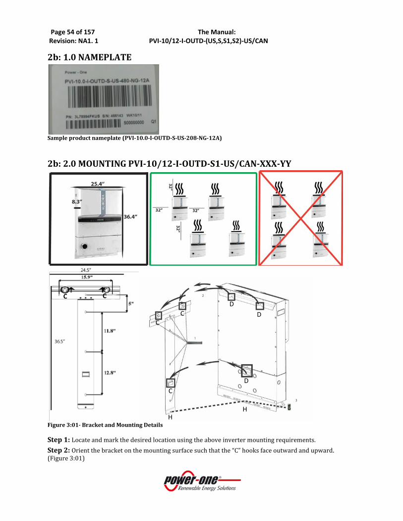
Page 54 of 157 The Manual: Revision: NA1. 1 PVI-10/12-I-OUTD-(US,S,S1,S2)-US/CAN
2b: 1.0 NAMEPLATE
Sample product nameplate (PVI-10.0-I-OUTD-S-US-208-NG-12A)
2b: 2.0 MOUNTING PVI-10/12-I-OUTD-S1-US/CAN-XXX-YY
Figure 3:01- Bracket and Mounting Details Step 1: Locate and mark the desired location using the above inverter mounting requirements. Step 2: Orient the bracket on the mounting surface such that the “C” hooks face outward and upward. (Figure 3:01)
C C
D D
H H
C D
C C

Page 55 of 157 The Manual: Revision: NA1. 1 PVI-10/12-I-OUTD-(US,S,S1,S2)-US/CAN
Step 3: Using the hardware provided, mount the bracket using mounting holes shown in Figure 3:01. Step 4: Hang the inverter on the mounted bracket by lifting the unit up over and above the mounting plate. Carefully guide the inverter and switchbox brackets into the mating upper and lower bracket hooks. Make sure the connecting points(C and D) in the bracket and in the back of the inverter engage properly. Step 5: Secure the bottom of the inverter using the machine screw (6x20mm) and washer (18mm diameter) provided. Insert machine screw through center hole (H; 3:01) of the bottom inverter mount and engage the PEMnut mounted in the bracket.
2b: 3.0 INSTALLATION PVI-10/12-I-OUTD-S1-US/CAN-XXX-YY 3.1 REMOVING THE FRONT COVERS To access the wiring terminals in the inverter and switchbox the inverter cover and switchbox cover must be removed. Refer to Figure 3:02
• To remove the front cover of the inverter compartment, loosen the six captive screws indicated using the Torx screwdriver provided.
• To remove the front cover of the switchbox Figure 3:02, loosen the six captive screws indicated using the Torx screwdriver provided in the box with the inverter.
• When connection operations are completed, re-install the front covers and tighten the cover screws with at least 1.5Nm (13.2 in-lbs) torque to ensure proper waterproof sealing.
Inverter coverTorx 20 screw, 6pl
Switchbox coverTorx 20 screw, 6pl
Figure 3:02- Location of Front Access Panels

Page 56 of 157 The Manual: Revision: NA1. 1 PVI-10/12-I-OUTD-(US,S,S1,S2)-US/CAN
2b: 3.2 ELECTRICAL WIRING AND CONNECTIONS PVI-10/12-I-OUTD-S1-US/CAN-XXX
DANGER
• This section is dedicated to initial installation wiring of the AURORA TRIO Inverter and assumes the unit has been physically mounted in its final location, but not yet wired.
• If the inverter has been previously wired and connected to the PV array and/or the AC grid, refer to Part 4 for Operations and Start Up Procedures.
2b: 3.3 CONSIDERATIONS BEFORE PERFORMING ELECTRICAL CONNECTIONS PVI-10/12-I-OUTD-S1-US/CAN-XXX-YY
This section provides a systematic description of correct wiring procedures. Please read the instructions provided and follow all safety warnings. Failure to comply with these instructions can result in safety hazards and may lead to possible injury to personnel and/or equipment damage.
WARNING
• Ensure wire sizing procedures are completed per appropriate local codes and regulations.
• Field wiring terminals for inverters are rated at 90°C/194°F. • Permanently mount the AURORA TRIO in its operational location prior to
beginning electrical connections. • Only qualified and properly trained personnel for the process of connecting the
AURORA Inverter to the electrical distribution grid, and only after receiving approval from the local authority having jurisdiction.
• Secure all signal wiring and cables to prevent contact with either AC grid and/or DC array field wiring; additionally, maintain spacing and between the AC grid wiring and DC array wiring; secure as necessary.
• Do not under any circumstances exceed the nominal ratings of voltage and current when designing the system. These include:
o Do not exceed the maximum array DC voltage input to each MPPT circuit of 520 Vdc under any condition.
o Do not exceed the maximum array DC current input of 24 Adc (10kW) or 25A (12kW) to each MPPT circuit.
o See data sheet information in Part 9: The Appendix
• An automatic over-current device (e.g., circuit breaker) must be used between the AURORA Inverter and the distribution grid.
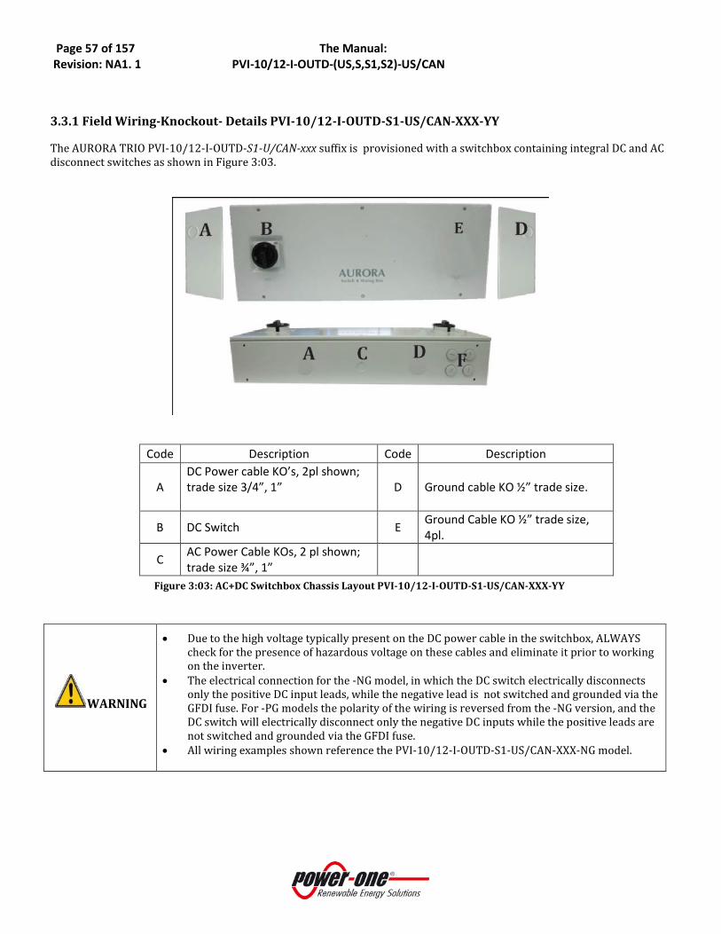
Page 57 of 157 The Manual: Revision: NA1. 1 PVI-10/12-I-OUTD-(US,S,S1,S2)-US/CAN
3.3.1 Field Wiring-Knockout- Details PVI-10/12-I-OUTD-S1-US/CAN-XXX-YY The AURORA TRIO PVI-10/12-I-OUTD-S1-U/CAN-xxx suffix is provisioned with a switchbox containing integral DC and AC disconnect switches as shown in Figure 3:03.
Code Description Code Description
A DC Power cable KO’s, 2pl shown; trade size 3/4”, 1”
D Ground cable KO ½” trade size.
B DC Switch E Ground Cable KO ½” trade size, 4pl.
C AC Power Cable KOs, 2 pl shown; trade size ¾”, 1”
Figure 3:03: AC+DC Switchbox Chassis Layout PVI-10/12-I-OUTD-S1-US/CAN-XXX-YY
WARNING
• Due to the high voltage typically present on the DC power cable in the switchbox, ALWAYS check for the presence of hazardous voltage on these cables and eliminate it prior to working on the inverter.
• The electrical connection for the -NG model, in which the DC switch electrically disconnects only the positive DC input leads, while the negative lead is not switched and grounded via the GFDI fuse. For -PG models the polarity of the wiring is reversed from the -NG version, and the DC switch will electrically disconnect only the negative DC inputs while the positive leads are not switched and grounded via the GFDI fuse.
• All wiring examples shown reference the PVI-10/12-I-OUTD-S1-US/CAN-XXX-NG model.

Page 58 of 157 The Manual: Revision: NA1. 1 PVI-10/12-I-OUTD-(US,S,S1,S2)-US/CAN
Location
Code Details Location Code Details
A DC Array conduit
entry (KOs, 3 places)
KO for ¾” and 1” trade size F AC grid conduit
entry (4 places) KO for ¾” and 1”
trade size
D Array PE Ground Note 1 G Main Ground Note 2
E DC Switch AC Grid Output Terminals 1, 2, 3, N Note 3,4
+IN1 DC Array MPPT 1 F1, F2, F3 Note 2
-IN1 DC Array MPPT 1 NEG Returns Note 1 J RS485 cable conduit
entry ½” trade size KO
+IN2 DC Array MPPT 2 F4, F5, F6 Note 2 K Plastic conduit to segregate signal cables
-IN2 DC Array MPPT 1 NEG Returns Note 1 BTx Busbar Terminals 1, 2,
3, 4 Note 5
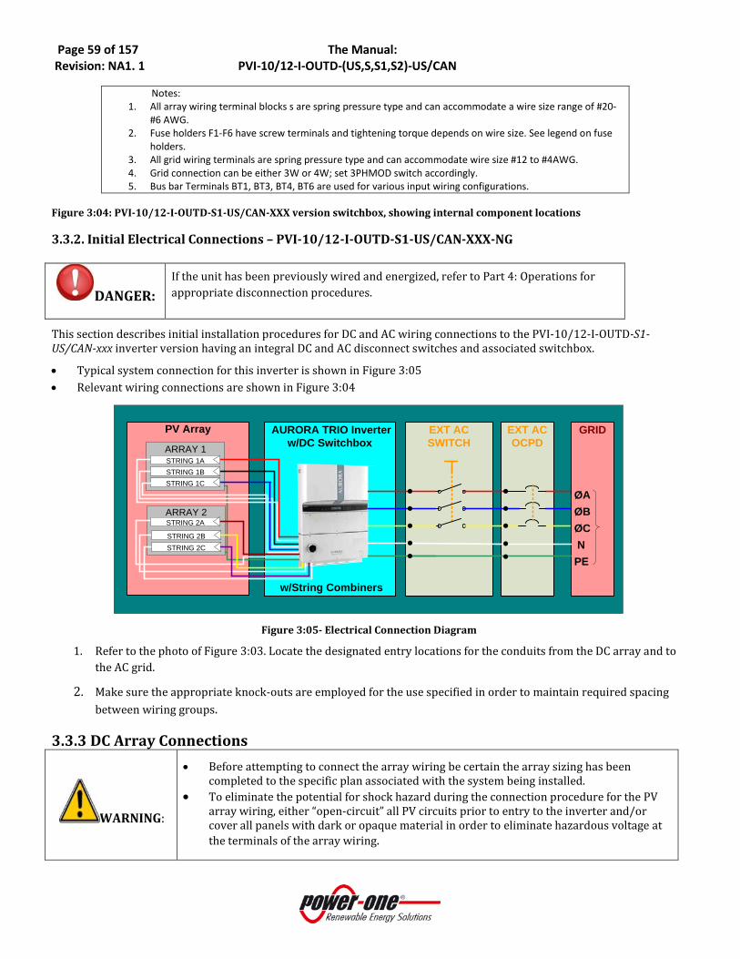
Page 59 of 157 The Manual: Revision: NA1. 1 PVI-10/12-I-OUTD-(US,S,S1,S2)-US/CAN
Notes: 1. All array wiring terminal blocks s are spring pressure type and can accommodate a wire size range of #20-
#6 AWG. 2. Fuse holders F1-F6 have screw terminals and tightening torque depends on wire size. See legend on fuse
holders. 3. All grid wiring terminals are spring pressure type and can accommodate wire size #12 to #4AWG. 4. Grid connection can be either 3W or 4W; set 3PHMOD switch accordingly. 5. Bus bar Terminals BT1, BT3, BT4, BT6 are used for various input wiring configurations.
Figure 3:04: PVI-10/12-I-OUTD-S1-US/CAN-XXX version switchbox, showing internal component locations
3.3.2. Initial Electrical Connections – PVI-10/12-I-OUTD-S1-US/CAN-XXX-NG
DANGER: If the unit has been previously wired and energized, refer to Part 4: Operations for appropriate disconnection procedures.
This section describes initial installation procedures for DC and AC wiring connections to the PVI-10/12-I-OUTD-S1-US/CAN-xxx inverter version having an integral DC and AC disconnect switches and associated switchbox.
• Typical system connection for this inverter is shown in Figure 3:05 • Relevant wiring connections are shown in Figure 3:04
AURORA TRIO Inverter w/DC Switchbox
PV Array
ARRAY 2
ARRAY 1
EXT AC SWITCH
EXT AC OCPD
GRID
ØAØBØC NPE
●●●●●
●●●●●
STRING 2B
STRING 2A
STRING 1ASTRING 1B
STRING 2C
STRING 1C
w/String Combiners
Figure 3:05- Electrical Connection Diagram
1. Refer to the photo of Figure 3:03. Locate the designated entry locations for the conduits from the DC array and to the AC grid.
2. Make sure the appropriate knock-outs are employed for the use specified in order to maintain required spacing between wiring groups.
3.3.3 DC Array Connections
WARNING:
• Before attempting to connect the array wiring be certain the array sizing has been completed to the specific plan associated with the system being installed.
• To eliminate the potential for shock hazard during the connection procedure for the PV array wiring, either “open-circuit” all PV circuits prior to entry to the inverter and/or cover all panels with dark or opaque material in order to eliminate hazardous voltage at the terminals of the array wiring.

Page 60 of 157 The Manual: Revision: NA1. 1 PVI-10/12-I-OUTD-(US,S,S1,S2)-US/CAN
Location Code Details
A DC Array conduit entry
(KOs, 3 places)
KO for ¾” and 1”
trade size
D Array PE Ground Note 1
E DC Switch
+IN1 DC Array MPPT 1
F1, F2, F3 Note 2
-IN1 DC Array MPPT 1
NEG Returns Note 1
+IN2 DC Array MPPT 2
F4, F5, F6 Note 2
-IN2 DC Array MPPT 1
NEG Returns Note 1
Notes:
1. All array wiring terminals are spring pressure type and can accommodate a wire size range of #20-#6 AWG.
2. Combiner fuse holders F1-F6 use screw terminals and 3. Bus bar Terminals BT1, BT3, BT4, BT6 are used for various input
wiring configurations.
Figure 3:06- DC Array Connection
• Refer to Figure 3:06. Locate the incoming DC array wiring at the switchbox chassis and measure the voltage to ensure the array output is non-hazardous.
• Once de-energized, connect the DC wiring to the MPPT1 and MPPT2 array terminals shown in inverter per the specific array design.
• If the array is wired for dual MPPT mode, run separate wires for POS and NEG for each array and ensure no jumpers are installed between the two inputs See section on Signal Wiring below for more information.
• If the array is designed for the parallel MPPT input mode, ensure the jumpers shown in Figure 3:12 are in place.
• Ensure the MPPT mode switch is in the correct position to match the array design.
WARNING:
When operating in PARallel mode jumpers must be connected in two places: - Connect bus bar terminals BT3 and BT4 together via a short #8AWG jumper - Connect terminal blocks -IN1 and -IN2 return terminals together using terminal block
jumpers found in hardware bag.

Page 61 of 157 The Manual: Revision: NA1. 1 PVI-10/12-I-OUTD-(US,S,S1,S2)-US/CAN
3.3.4 AC Grid Connections
Location Code
Details
G Main Ground Note 1
AC Grid Output Terminals [1, 2, 3, N] Note 1,2
Notes:
1. All grid wiring terminals are spring pressure type and can accommodate wire size #12-#4 AWG.
2. Grid connection can be either 3W or 4W; 3PHMOD switch must be set accordingly.
Figure 3:07 AC Grid Connections
• Refer to Figure 3:07. Locate the AC grid wiring at the inverter switchbox. Measure the voltage to ensure all connections to the grid have been eliminated and no hazardous voltage is present.
• Once de-energized, connect the AC wiring to the AC grid terminals. a. If the grid connection is to be 3W, the Neutral conductor does not need to be pulled or connected.
Place the 3PHMOD switch in the 3W position. b. If the grid connection is to be 4W, the Neutral connection must be provisioned and connected to the
Neutral terminal. Place the 3PHMOD switch in the 4W position.
3.3.5 Signal Wiring Connections –PVI-10/12-I-OUTD-S1-US/CAN-XXX-NG
Figure 3:08 Signal Wire Routing
Code Details
J RS485 Cable conduit entry (KOs) ½” trade size
K Plastic conduit for signal cables
• Route the cables through the switchbox and into the inverter chassis using plastic guide (item K, Figure 3:08).
• Refer to Figure 3:03. Note the position where the monitoring and alarm cables (if used) enter the chassis. • Refer to Figure 3:09. Locate the terminals for the alarm and monitoring connections within the chassis. • Connect alarm cable to the mating connector (in hardware kit) and plug connector into position shown in
Figure 3:04 • Connect RS485 monitoring cable:
a). If using CAT5 cable for monitoring connections, connect RJ45 plug to end of cable as shown in Table 3, and plug into RJ45 jack shown in Table 03. A second jack is available to accommodate daisy chaining of communication line to other inverters.

Page 62 of 157 The Manual: Revision: NA1. 1 PVI-10/12-I-OUTD-(US,S,S1,S2)-US/CAN
Figure 3:09: Standard RS485 connection
3: 3.4 Possible AURORA Inverter DC Input Configuration The Aurora inverter is configurable with an independent MPPT for each DC input channel or with the two input DC channels connected in parallel with one MPPT. If the inverter is configured with two independent MPPTs, the max current for each channel shall not exceed 24 Adc (10kW) or 25Adc (12kW) and the power input for the single channel shall not exceed 6.8 kW.
Figure 2:10: Configuration Settings
COUNTRY CODE SELECTOR 3-PHMOD SWITCH PAR/IND INMODE SWITCH
1:
3W-Δ
4W-Y
3:
PAR
IND
2:
S2 switch
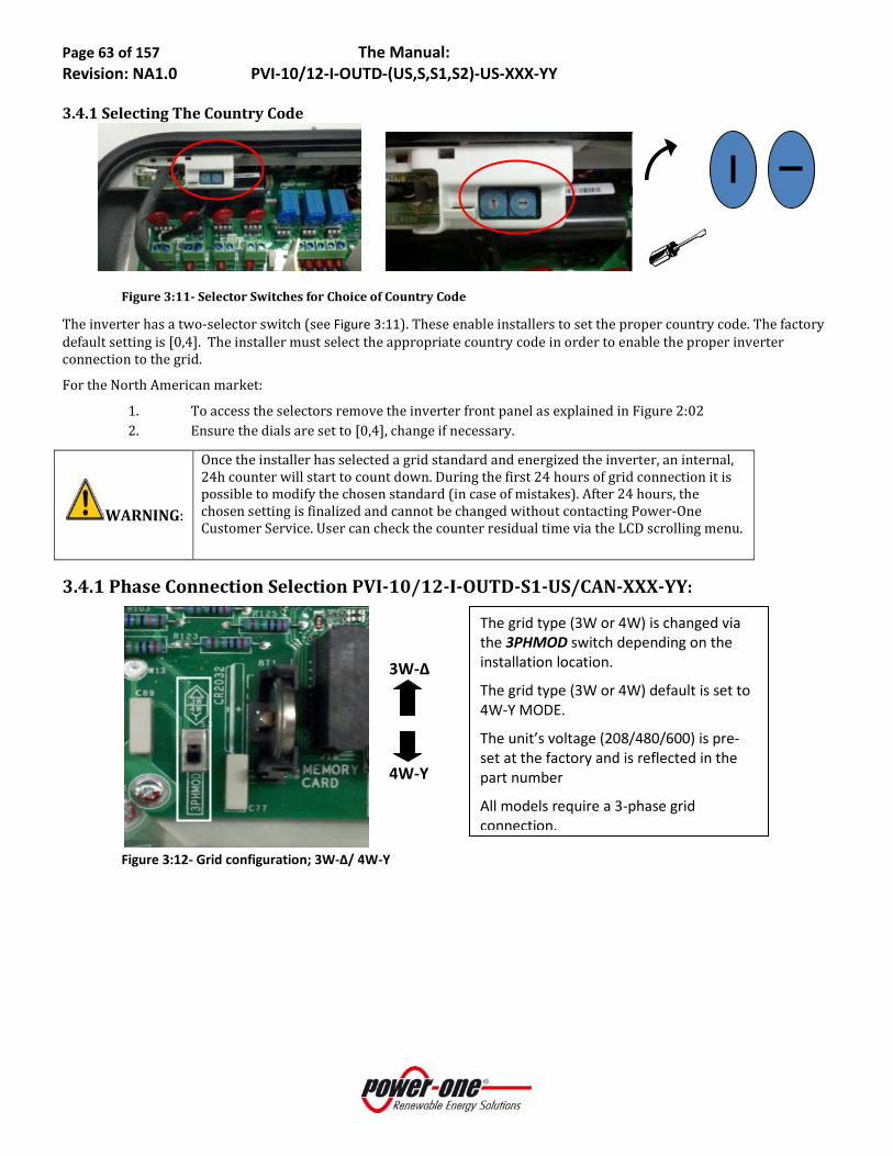
Page 63 of 157 The Manual: Revision: NA1.0 PVI-10/12-I-OUTD-(US,S,S1,S2)-US-XXX-YY
3.4.1 Selecting The Country Code
Figure 3:11- Selector Switches for Choice of Country Code
The inverter has a two-selector switch (see Figure 3:11). These enable installers to set the proper country code. The factory default setting is [0,4]. The installer must select the appropriate country code in order to enable the proper inverter connection to the grid.
For the North American market:
1. To access the selectors remove the inverter front panel as explained in Figure 2:02 2. Ensure the dials are set to [0,4], change if necessary.
WARNING:
Once the installer has selected a grid standard and energized the inverter, an internal, 24h counter will start to count down. During the first 24 hours of grid connection it is possible to modify the chosen standard (in case of mistakes). After 24 hours, the chosen setting is finalized and cannot be changed without contacting Power-One Customer Service. User can check the counter residual time via the LCD scrolling menu.
3.4.1 Phase Connection Selection PVI-10/12-I-OUTD-S1-US/CAN-XXX-YY:
Figure 3:12- Grid configuration; 3W-Δ/ 4W-Y
3W-Δ
4W-Y
The grid type (3W or 4W) is changed via the 3PHMOD switch depending on the installation location.
The grid type (3W or 4W) default is set to 4W-Y MODE.
The unit’s voltage (208/480/600) is pre-set at the factory and is reflected in the part number
All models require a 3-phase grid connection.
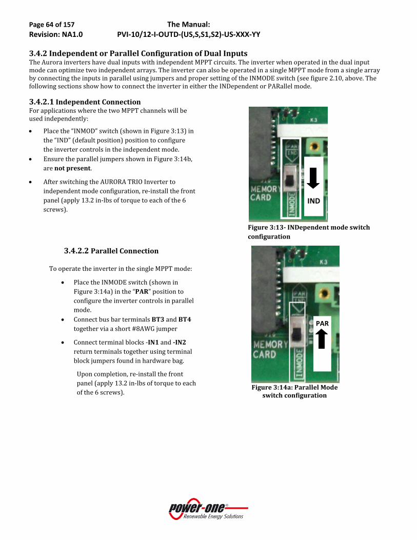
Page 64 of 157 The Manual: Revision: NA1.0 PVI-10/12-I-OUTD-(US,S,S1,S2)-US-XXX-YY
3.4.2 Independent or Parallel Configuration of Dual InputsThe Aurora inverters have dual inputs with independent MPPT circuits. The inverter when operated in the dual input mode can optimize two independent arrays. The inverter can also be operated in a single MPPT mode from a single array by connecting the inputs in parallel using jumpers and proper setting of the INMODE switch (see figure 2.10, above. The following sections show how to connect the inverter in either the INDependent or PARallel mode.
3.4.2.1 Independent Connection For applications where the two MPPT channels will be used independently:
• Place the “INMOD” switch (shown in Figure 3:13) in the “IND” (default position) position to configure the inverter controls in the independent mode.
• Ensure the parallel jumpers shown in Figure 3:14b, are not present.
• After switching the AURORA TRIO Inverter to independent mode configuration, re-install the front panel (apply 13.2 in-lbs of torque to each of the 6 screws).
Figure 3:13- INDependent mode switch configuration
3.4.2.2 Parallel Connection To operate the inverter in the single MPPT mode:
• Place the INMODE switch (shown in Figure 3:14a) in the “PAR” position to configure the inverter controls in parallel mode.
• Connect bus bar terminals BT3 and BT4 together via a short #8AWG jumper
• Connect terminal blocks -IN1 and -IN2 return terminals together using terminal block jumpers found in hardware bag.
Upon completion, re-install the front panel (apply 13.2 in-lbs of torque to each of the 6 screws).
Figure 3:14a: Parallel Mode
switch configuration
PAR
IND

Page 65 of 157 The Manual: Revision: NA1.0 PVI-10/12-I-OUTD-(US,S,S1,S2)-US-XXX-YY
MPPT#1T1+ T2+
Switch Box Chassis
10kW/12kW [-S or -S2] DC Wiring – POS Ground Version –
PARallel mode onlyWith 2x3 String Fuse Combiner
Capable of landing 6 StringsAdd #8AWG wire jumper between busbars
Add terminal block jumper to RTN terminal blocks
MPPT#2 T1-
Inverter Chassis
DC Switch
-IN2-IN1 -IN1 -IN2
Bus bar assy 1 Bus bar assy 2
-------[-IN1]-------F1 F2 F3
-------[-IN2]-------F4 F5 F6
T2- T2- T1+ T1- T2+
+IN2 +IN2+IN1 +IN1
1- 2- 3- | 4- 5- 6-MPPT #1 | MPPT #2
NEG Fused
| 1-3 | 4-6 | | POS String | | Returns |
Figure 3:14b: Large switchbox with combiners showing jumpers (circled) required for Parallel MPPT Input Connection

Page 66 of 157 The Manual: Revision: NA1.1 PVI-10/12-I-OUTD-(US,S,S1,S2)-US/CAN
SECTION 3: PVI-10/12-I-OUTD-S2-US/CAN-XXX
SECTION 3a: SECTION 3b: PVI-10/12-I-OUTD-S2-US/CAN-XXX PVI-10/12-I-OUTD-S2-US/CAN-XXX Without fuse holders With fuse holders

Page 67 of 157 The Manual: Revision: NA1.1 PVI-10/12-I-OUTD-(US,S,S1,S2)-US/CAN
SECTION 3a: PVI-10/12-I-OUTD-S2-US/CAN-XXX Without fuse holders

Page 68 of 157 The Manual: Revision: NA1.1 PVI-10/12-I-OUTD-(US,S,S1,S2)-US/CAN
3a: 1.0 NAMEPLATE
Sample product nameplate (PVI-10.0-I-OUTD-S2-US-480-NG)
3a: 2.0 MOUNTING PVI-10/12-I-OUTD-S2-US-XXX-YY
Figure 3:01- Bracket and Mounting Details Step 1: Locate and mark the desired location using the above inverter mounting requirements.
C C
D D
H H
C D
C C
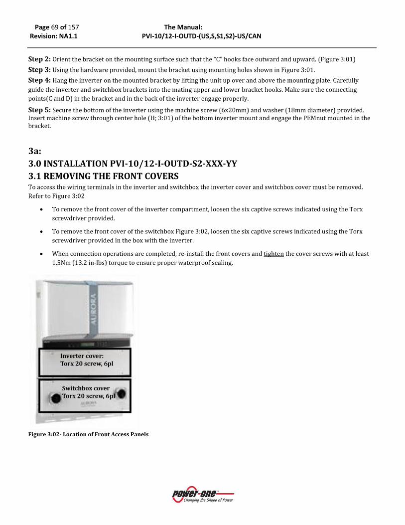
Page 69 of 157 The Manual: Revision: NA1.1 PVI-10/12-I-OUTD-(US,S,S1,S2)-US/CAN
Step 2: Orient the bracket on the mounting surface such that the “C” hooks face outward and upward. (Figure 3:01) Step 3: Using the hardware provided, mount the bracket using mounting holes shown in Figure 3:01. Step 4: Hang the inverter on the mounted bracket by lifting the unit up over and above the mounting plate. Carefully guide the inverter and switchbox brackets into the mating upper and lower bracket hooks. Make sure the connecting points(C and D) in the bracket and in the back of the inverter engage properly. Step 5: Secure the bottom of the inverter using the machine screw (6x20mm) and washer (18mm diameter) provided. Insert machine screw through center hole (H; 3:01) of the bottom inverter mount and engage the PEMnut mounted in the bracket.
3a: 3.0 INSTALLATION PVI-10/12-I-OUTD-S2-XXX-YY 3.1 REMOVING THE FRONT COVERS To access the wiring terminals in the inverter and switchbox the inverter cover and switchbox cover must be removed. Refer to Figure 3:02
• To remove the front cover of the inverter compartment, loosen the six captive screws indicated using the Torx screwdriver provided.
• To remove the front cover of the switchbox Figure 3:02, loosen the six captive screws indicated using the Torx screwdriver provided in the box with the inverter.
• When connection operations are completed, re-install the front covers and tighten the cover screws with at least 1.5Nm (13.2 in-lbs) torque to ensure proper waterproof sealing.
Figure 3:02- Location of Front Access Panels

Page 70 of 157 The Manual: Revision: NA1.1 PVI-10/12-I-OUTD-(US,S,S1,S2)-US/CAN
3a: 3.2. ELECTRICAL WIRING AND CONNECTIONS PVI-10/12-I-OUTD-S2-US-XXX-YY
DANGER
• This section is dedicated to initial installation wiring of the AURORA TRIO Inverter and assumes the unit has been physically mounted in its final location, but not yet wired.
• If the inverter has been previously wired and connected to the PV array and/or the AC grid, refer to Part 4 for Operations and Start Up Procedures.
3.2.1 CONSIDERATIONS BEFORE PERFORMING ELECTRICAL CONNECTIONS
PVI-10/12-I-OUTD-S2-US-XXX-YY This section provides a systematic description of correct wiring procedures. Please read the instructions provided and follow all safety warnings. Failure to comply with these instructions can result in safety hazards and may lead to possible injury to personnel and/or equipment damage.
WARNING
• Ensure wire sizing procedures are completed per appropriate local codes and regulations.
• Field wiring terminals for inverters are rated at 90°C/194°F. • Permanently mount the AURORA TRIO in its operational location prior to
beginning electrical connections. • Only qualified and properly trained personnel for the process of connecting the
AURORA Inverter to the electrical distribution grid, and only after receiving approval from the local authority having jurisdiction.
• Secure all signal wiring and cables to prevent contact with either AC grid and/or DC array field wiring; additionally, maintain spacing and between the AC grid wiring and DC array wiring; secure as necessary.
• Do not under any circumstances exceed the nominal ratings of voltage and current when designing the system. These include: o Do not exceed the maximum array DC voltage input to each MPPT circuit of
520 Vdc under any condition. o Do not exceed the maximum array DC current input of 24 Adc (10kW) or 25A
(12kW) to each MPPT circuit.
o See data sheet information in Part 9: The Appendix
• An automatic over-current device (e.g., circuit breaker) must be used between the AURORA Inverter and the distribution grid.
3.2.2 Field Wiring-Knockout- Details PVI-10/12-I-OUTD-S2-US-XXX-YY The AURORA TRIO PVI-10/12-I-OUTD-S2-US-xxx suffix is provisioned with a switchbox containing integral DC and AC disconnect switches as shown in Figure 3:03.
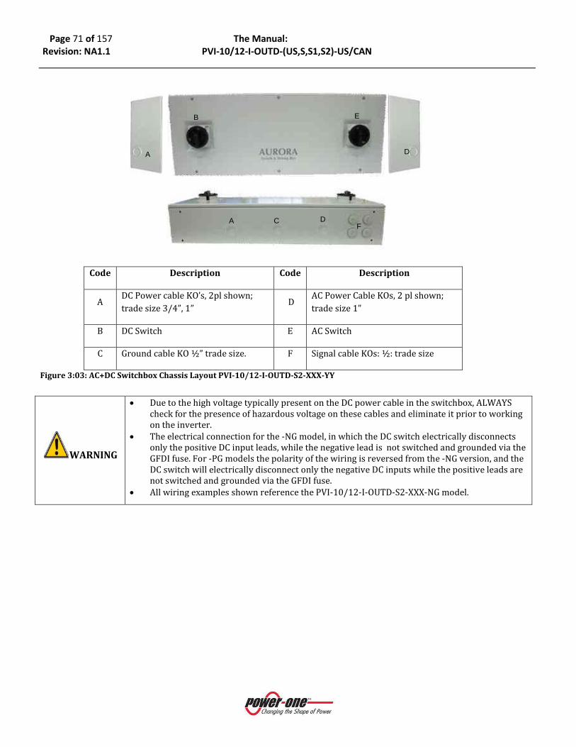
Page 71 of 157 The Manual: Revision: NA1.1 PVI-10/12-I-OUTD-(US,S,S1,S2)-US/CAN
Code Description Code Description
A DC Power cable KO’s, 2pl shown; trade size 3/4”, 1”
D AC Power Cable KOs, 2 pl shown; trade size 1”
B DC Switch E AC Switch
C Ground cable KO ½” trade size. F Signal cable KOs: ½: trade size
Figure 3:03: AC+DC Switchbox Chassis Layout PVI-10/12-I-OUTD-S2-XXX-YY
WARNING
• Due to the high voltage typically present on the DC power cable in the switchbox, ALWAYS check for the presence of hazardous voltage on these cables and eliminate it prior to working on the inverter.
• The electrical connection for the -NG model, in which the DC switch electrically disconnects only the positive DC input leads, while the negative lead is not switched and grounded via the GFDI fuse. For -PG models the polarity of the wiring is reversed from the -NG version, and the DC switch will electrically disconnect only the negative DC inputs while the positive leads are not switched and grounded via the GFDI fuse.
• All wiring examples shown reference the PVI-10/12-I-OUTD-S2-XXX-NG model.
A D
B E
A DF
C
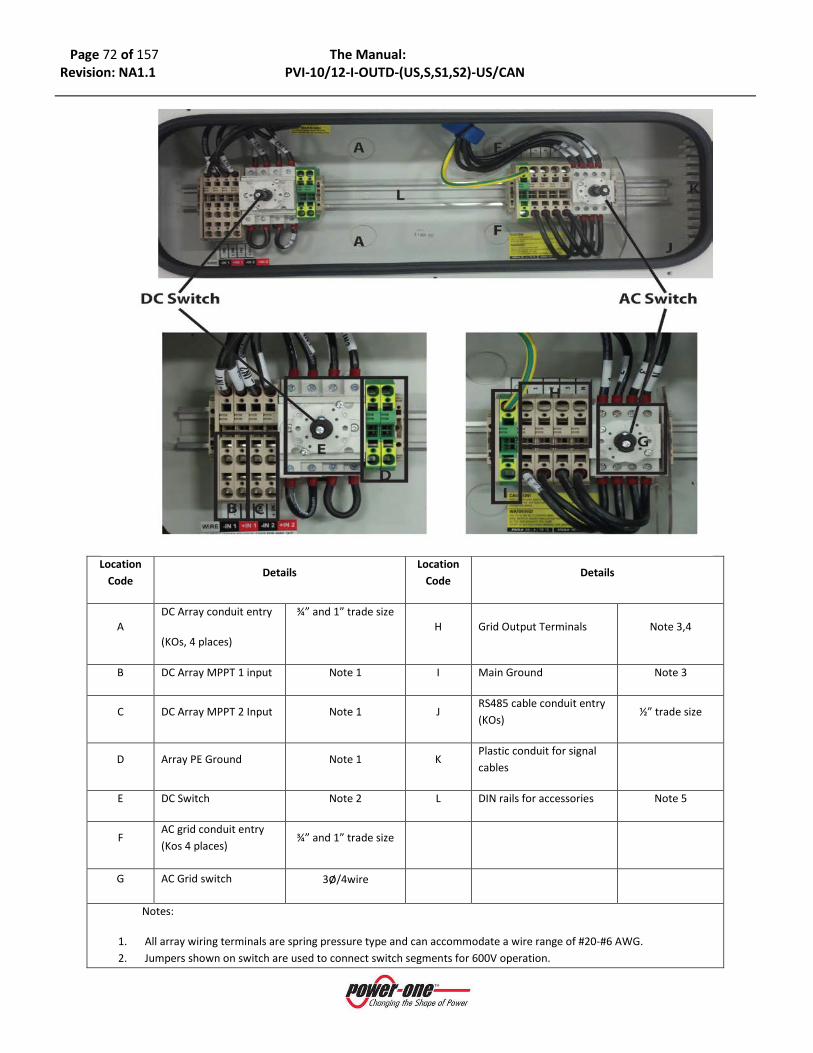
Page 72 of 157 The Manual: Revision: NA1.1 PVI-10/12-I-OUTD-(US,S,S1,S2)-US/CAN
Location
Code Details
Location Code
Details
A DC Array conduit entry
(KOs, 4 places)
¾” and 1” trade size
H Grid Output Terminals Note 3,4
B DC Array MPPT 1 input Note 1 I Main Ground Note 3
C DC Array MPPT 2 Input Note 1 J RS485 cable conduit entry (KOs)
½” trade size
D Array PE Ground Note 1 K Plastic conduit for signal cables
E DC Switch Note 2 L DIN rails for accessories Note 5
F AC grid conduit entry (Kos 4 places)
¾” and 1” trade size
G AC Grid switch 3ø/4wire
Notes:
1. All array wiring terminals are spring pressure type and can accommodate a wire range of #20-#6 AWG. 2. Jumpers shown on switch are used to connect switch segments for 600V operation.
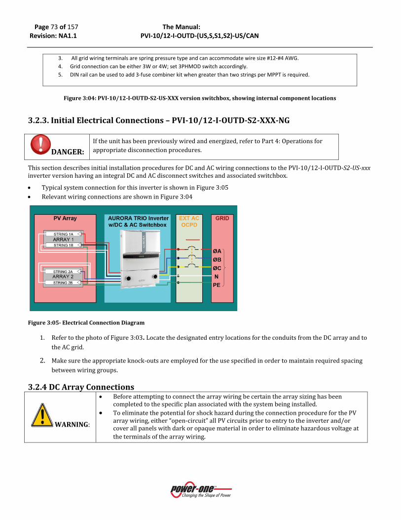
Page 73 of 157 The Manual: Revision: NA1.1 PVI-10/12-I-OUTD-(US,S,S1,S2)-US/CAN
3. All grid wiring terminals are spring pressure type and can accommodate wire size #12-#4 AWG. 4. Grid connection can be either 3W or 4W; set 3PHMOD switch accordingly. 5. DIN rail can be used to add 3-fuse combiner kit when greater than two strings per MPPT is required.
Figure 3:04: PVI-10/12-I-OUTD-S2-US-XXX version switchbox, showing internal component locations
3.2.3. Initial Electrical Connections – PVI-10/12-I-OUTD-S2-XXX-NG
DANGER: If the unit has been previously wired and energized, refer to Part 4: Operations for appropriate disconnection procedures.
This section describes initial installation procedures for DC and AC wiring connections to the PVI-10/12-I-OUTD-S2-US-xxx inverter version having an integral DC and AC disconnect switches and associated switchbox.
• Typical system connection for this inverter is shown in Figure 3:05 • Relevant wiring connections are shown in Figure 3:04
Figure 3:05- Electrical Connection Diagram
1. Refer to the photo of Figure 3:03. Locate the designated entry locations for the conduits from the DC array and to the AC grid.
2. Make sure the appropriate knock-outs are employed for the use specified in order to maintain required spacing between wiring groups.
3.2.4 DC Array Connections
WARNING:
• Before attempting to connect the array wiring be certain the array sizing has been completed to the specific plan associated with the system being installed.
• To eliminate the potential for shock hazard during the connection procedure for the PV array wiring, either “open-circuit” all PV circuits prior to entry to the inverter and/or cover all panels with dark or opaque material in order to eliminate hazardous voltage at the terminals of the array wiring.

Page 74 of 157 The Manual: Revision: NA1.1 PVI-10/12-I-OUTD-(US,S,S1,S2)-US/CAN
Figure 3:06- DC Array Connection
• Refer to Figure 3:06. Locate the incoming DC array wiring at the switchbox chassis and measure the
voltage to ensure the array output is non-hazardous. • Once de-energized, connect the DC wiring to the MPPT1 and MPPT2 array terminals shown in inverter
per the specific array design. • If the array is wired for dual MPPT mode, run separate wires for POS and NEG for each array and ensure
no jumpers are installed between the two inputs See section on Signal Wiring below for more information. • If the array is designed for the parallel MPPT input mode, ensure the jumpers shown in Figure 3:12 are in
place. • Ensure the MPPT mode switch is in the correct position to match the array design.
3.2.5 AC Grid Connections
Figure 3:07 AC Grid Connections
Location Code
Details
B DC Array MPPT 1 input
C DC Array MPPT 2 Input Note 1
D Array PE Ground Note 1
E DC Switch Note 2
Notes:
1. All array wiring terminals are spring pressure type and can accommodate #20-#6 AWG.
2. Jumpers shown used to connect segments of DC switch for 600V operation
WARNING: When operating in PAR mode the input terminals in the switchbox must also be wired in parallel to ensure current through switch is equalized.
Location Code
Details
G AC Grid switch 3ø/4wire
H Grid Output Terminals Note 1, 2
I Main Ground Note 1
Notes:
1. All grid wiring terminals are spring pressure type and can accommodate wire sizes #12 to #4AWG.
2. Grid connection can be either 3W or 4W; set 3PHMOD switch accordingly
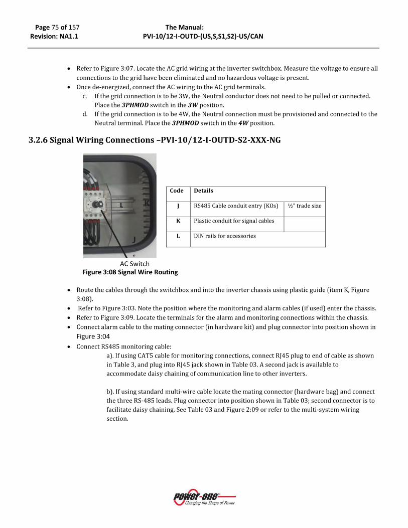
Page 75 of 157 The Manual: Revision: NA1.1 PVI-10/12-I-OUTD-(US,S,S1,S2)-US/CAN
• Refer to Figure 3:07. Locate the AC grid wiring at the inverter switchbox. Measure the voltage to ensure all
connections to the grid have been eliminated and no hazardous voltage is present. • Once de-energized, connect the AC wiring to the AC grid terminals.
c. If the grid connection is to be 3W, the Neutral conductor does not need to be pulled or connected. Place the 3PHMOD switch in the 3W position.
d. If the grid connection is to be 4W, the Neutral connection must be provisioned and connected to the Neutral terminal. Place the 3PHMOD switch in the 4W position.
3.2.6 Signal Wiring Connections –PVI-10/12-I-OUTD-S2-XXX-NG
Figure 3:08 Signal Wire Routing
• Route the cables through the switchbox and into the inverter chassis using plastic guide (item K, Figure 3:08).
• Refer to Figure 3:03. Note the position where the monitoring and alarm cables (if used) enter the chassis. • Refer to Figure 3:09. Locate the terminals for the alarm and monitoring connections within the chassis. • Connect alarm cable to the mating connector (in hardware kit) and plug connector into position shown in
Figure 3:04 • Connect RS485 monitoring cable:
a). If using CAT5 cable for monitoring connections, connect RJ45 plug to end of cable as shown in Table 3, and plug into RJ45 jack shown in Table 03. A second jack is available to accommodate daisy chaining of communication line to other inverters.
b). If using standard multi-wire cable locate the mating connector (hardware bag) and connect the three RS-485 leads. Plug connector into position shown in Table 03; second connector is to facilitate daisy chaining. See Table 03 and Figure 2:09 or refer to the multi-system wiring section.
Code Details
J RS485 Cable conduit entry (KOs) ½” trade size
K Plastic conduit for signal cables
L DIN rails for accessories
AC Switch
L
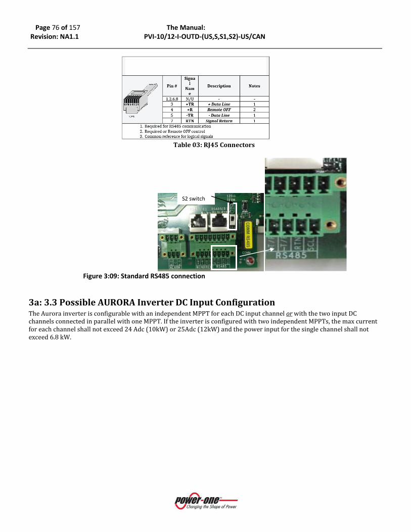
Page 76 of 157 The Manual: Revision: NA1.1 PVI-10/12-I-OUTD-(US,S,S1,S2)-US/CAN
Table 03: RJ45 Connectors
Figure 3:09: Standard RS485 connection
3a: 3.3 Possible AURORA Inverter DC Input Configuration The Aurora inverter is configurable with an independent MPPT for each DC input channel or with the two input DC channels connected in parallel with one MPPT. If the inverter is configured with two independent MPPTs, the max current for each channel shall not exceed 24 Adc (10kW) or 25Adc (12kW) and the power input for the single channel shall not exceed 6.8 kW.
S2 switch

Page 77 of 157 The Manual: Revision: NA1.1 PVI-10/12-I-OUTD-(US,S,S1,S2)-US/CAN
Figure 2:10: Configuration Settings
COUNTRY CODE SELECTOR 3PHMOD SWITCH PAR/IND INMODE SWITCH
3.3.1 Selecting The Country Code
Figure 3:11- Selector Switches for Choice of Country Code
1:
3WΔ
4WY
3:
PAR
IND
2:
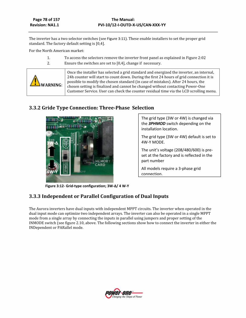
Page 78 of 157 The Manual: Revision: NA1.1 PVI-10/12-I-OUTD-X-US/CAN-XXX-YY
The inverter has a two selector switches (see Figure 3:11). These enable installers to set the proper grid standard. The factory default setting is [0,4].
For the North American market:
1. To access the selectors remove the inverter front panel as explained in Figure 2:02 2. Ensure the switches are set to [0,4], change if necessary.
WARNING:
Once the installer has selected a grid standard and energized the inverter, an internal, 24h counter will start to count down. During the first 24 hours of grid connection it is possible to modify the chosen standard (in case of mistakes). After 24 hours, the chosen setting is finalized and cannot be changed without contacting Power-One Customer Service. User can check the counter residual time via the LCD scrolling menu.
3.3.2 Gride Type Connection: Three-Phase Selection
Figure 3:12- Grid-type configuration; 3W-Δ/ 4 W-Y
3.3.3 Independent or Parallel Configuration of Dual Inputs
The Aurora inverters have dual inputs with independent MPPT circuits. The inverter when operated in the dual input mode can optimize two independent arrays. The inverter can also be operated in a single MPPT mode from a single array by connecting the inputs in parallel using jumpers and proper setting of the INMODE switch (see figure 2.10, above. The following sections show how to connect the inverter in either the INDependent or PARallel mode.
3W-Δ
4W-Y
The grid type (3W or 4W) is changed via the 3PHMOD switch depending on the installation location.
The grid type (3W or 4W) default is set to 4W-Y MODE.
The unit’s voltage (208/480/600) is pre-set at the factory and is reflected in the part number
All models require a 3-phase grid connection.

Page 79 of 157 The Manual: Revision: NA1.1 PVI-10/12-I-OUTD-X-US/CAN-XXX-YY
3.3.3.1 Independent Connection For applications where the two MPPT channels will be used independently:
• Place switch “INMOD” switch (shown in Figure 3:13) in the “IND” (default position) position to configure the inverter controls in the independent mode.
• Ensure the parallel jumper wiring (see Figure 3:14b), is not present.
• After switching the AURORA TRIO Inverter to independent mode configuration, re-install the front panel (apply 13.2 in-lbs of torque to each of the 6 screws).
Figure 3:13- Independent Configuration Switch
3.3.3.2 Parallel Connection To operate the inverter in the single MPPT mode:
• Place switch INMODE switch (shown in Figure 3:14a) in the “PAR” in order to configure the inverter controls in parallel mode.
• Add wire jumper (#8 AWG) between bus bar terminals BT3 and BT4
• Add terminal block jumper between as shown in Figure 14b using two#10 AWG jumper wires (1 black and 1 red cable) to connect the input.
• After switching the AURORA TRIO Inverter to parallel mode configuration, re-install the front panel (apply 13.2 in-lbs of torque to each of the 6 screws).
Figure 3:14a: Parallel Mode
Configuration Switch
IND
PAR

Page 80 of 157 The Manual: Revision: NA1.1 PVI-10/12-I-OUTD-X-US/CAN-XXX-YY
MPPT#1
T1+ T2+ T2-
Switch Box Chassis
T1- MPPT#2
T1+ T2+ T2- T1-
Inverter Chassis
+IN1-IN1 -IN2 +IN2
Switch BoxDC TB
DC Switch
10kW/12kW [-S or -S2] DC Wiring– Neg Ground Version –
As shipped SEP2011Connected in PARallel mode
Capable of landing up to 2 Strings Use two #8AWG wire jumpers to parallel channels
Figure 3:14b: Jumpers for Parallel MPPT Input Connection

Page 81 of 157 The Manual: Revision: NA1.1 PVI-10/12-I-OUTD-X-US/CAN-XXX-YY
SECTION 3b: PVI-10/12-I-OUTD-S2-US/CAN-XXX With fuse holders
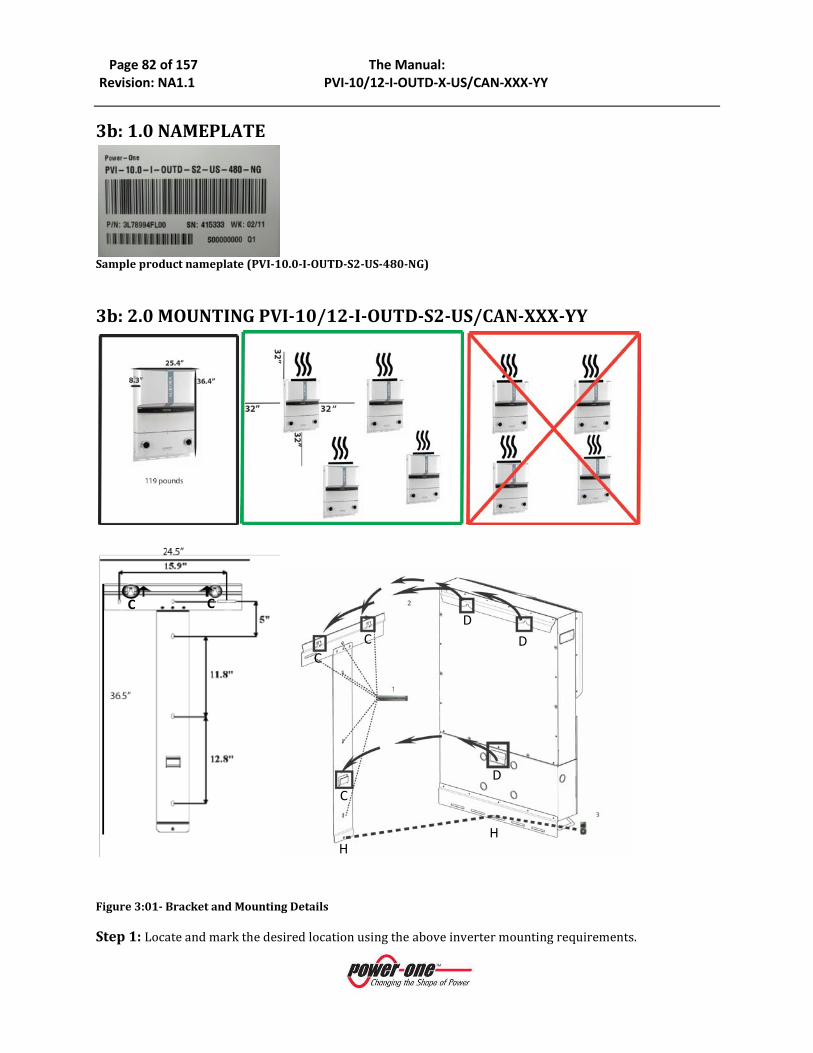
Page 82 of 157 The Manual: Revision: NA1.1 PVI-10/12-I-OUTD-X-US/CAN-XXX-YY
3b: 1.0 NAMEPLATE
Sample product nameplate (PVI-10.0-I-OUTD-S2-US-480-NG)
3b: 2.0 MOUNTING PVI-10/12-I-OUTD-S2-US/CAN-XXX-YY
Figure 3:01- Bracket and Mounting Details Step 1: Locate and mark the desired location using the above inverter mounting requirements.
C C
D D
H H
C D
C C
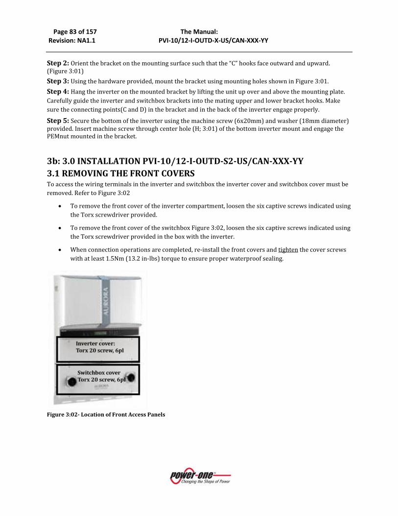
Page 83 of 157 The Manual: Revision: NA1.1 PVI-10/12-I-OUTD-X-US/CAN-XXX-YY
Step 2: Orient the bracket on the mounting surface such that the “C” hooks face outward and upward. (Figure 3:01) Step 3: Using the hardware provided, mount the bracket using mounting holes shown in Figure 3:01. Step 4: Hang the inverter on the mounted bracket by lifting the unit up over and above the mounting plate. Carefully guide the inverter and switchbox brackets into the mating upper and lower bracket hooks. Make sure the connecting points(C and D) in the bracket and in the back of the inverter engage properly. Step 5: Secure the bottom of the inverter using the machine screw (6x20mm) and washer (18mm diameter) provided. Insert machine screw through center hole (H; 3:01) of the bottom inverter mount and engage the PEMnut mounted in the bracket.
3b: 3.0 INSTALLATION PVI-10/12-I-OUTD-S2-US/CAN-XXX-YY 3.1 REMOVING THE FRONT COVERS To access the wiring terminals in the inverter and switchbox the inverter cover and switchbox cover must be removed. Refer to Figure 3:02
• To remove the front cover of the inverter compartment, loosen the six captive screws indicated using the Torx screwdriver provided.
• To remove the front cover of the switchbox Figure 3:02, loosen the six captive screws indicated using the Torx screwdriver provided in the box with the inverter.
• When connection operations are completed, re-install the front covers and tighten the cover screws with at least 1.5Nm (13.2 in-lbs) torque to ensure proper waterproof sealing.
Figure 3:02- Location of Front Access Panels

Page 84 of 157 The Manual: Revision: NA1.0 PVI-10/12-I-OUTD-(US,S,S1,S2)-US/CAN
3b: 3.2. ELECTRICAL WIRING AND CONNECTIONS PVI-10/12-I-OUTD-S2-US/CAN-XXX-YY
DANGER
• This section is dedicated to initial installation wiring of the AURORA TRIO Inverter and assumes the unit has been physically mounted in its final location, but not yet wired.
• If the inverter has been previously wired and connected to the PV array and/or the AC grid, refer to Part 4 for Operations and Start Up Procedures.
3.2.1 CONSIDERATIONS BEFORE PERFORMING ELECTRICAL CONNECTIONS
PVI-10/12-I-OUTD-S2-US/CAN-XXX-YY This section provides a systematic description of correct wiring procedures. Please read the instructions provided and follow all safety warnings. Failure to comply with these instructions can result in safety hazards and may lead to possible injury to personnel and/or equipment damage.
WARNING
• Ensure wire sizing procedures are completed per appropriate local codes and regulations.
• Field wiring terminals for inverters are rated at 90°C/194°F. • Permanently mount the AURORA TRIO in its operational location prior to
beginning electrical connections. • Only qualified and properly trained personnel for the process of connecting the
AURORA Inverter to the electrical distribution grid, and only after receiving approval from the local authority having jurisdiction.
• Secure all signal wiring and cables to prevent contact with either AC grid and/or DC array field wiring; additionally, maintain spacing and between the AC grid wiring and DC array wiring; secure as necessary.
• Do not under any circumstances exceed the nominal ratings of voltage and current when designing the system. These include:
o Do not exceed the maximum array DC voltage input to each MPPT circuit of 520 Vdc under any condition.
o Do not exceed the maximum array DC current input of 24 Adc (10kW) or 25A (12kW) to each MPPT circuit.
o See data sheet information in Part 9: The Appendix
• An automatic over-current device (e.g., circuit breaker) must be used between the AURORA Inverter and the distribution grid.
3.2.2 Field Wiring-Knockout- Details PVI-10/12-I-OUTD-S2-US/CAN-XXX-YY The AURORA TRIO PVI-10/12-I-OUTD-S2-US/CAN-xxx suffix is provisioned with a switchbox containing integral DC and AC disconnect switches as shown in Figure 3:03.
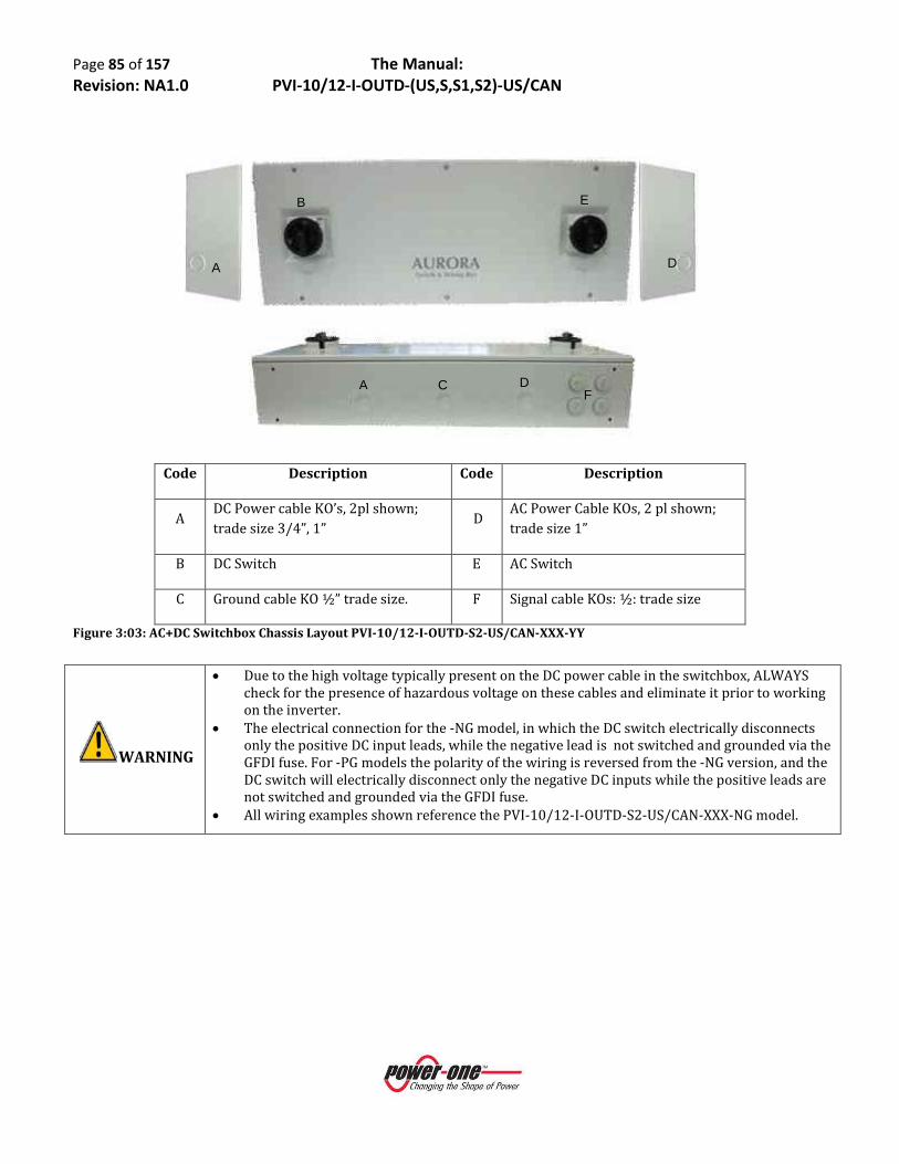
Page 85 of 157 The Manual: Revision: NA1.0 PVI-10/12-I-OUTD-(US,S,S1,S2)-US/CAN
Code Description Code Description
A DC Power cable KO’s, 2pl shown; trade size 3/4”, 1”
D AC Power Cable KOs, 2 pl shown; trade size 1”
B DC Switch E AC Switch
C Ground cable KO ½” trade size. F Signal cable KOs: ½: trade size
Figure 3:03: AC+DC Switchbox Chassis Layout PVI-10/12-I-OUTD-S2-US/CAN-XXX-YY
WARNING
• Due to the high voltage typically present on the DC power cable in the switchbox, ALWAYS check for the presence of hazardous voltage on these cables and eliminate it prior to working on the inverter.
• The electrical connection for the -NG model, in which the DC switch electrically disconnects only the positive DC input leads, while the negative lead is not switched and grounded via the GFDI fuse. For -PG models the polarity of the wiring is reversed from the -NG version, and the DC switch will electrically disconnect only the negative DC inputs while the positive leads are not switched and grounded via the GFDI fuse.
• All wiring examples shown reference the PVI-10/12-I-OUTD-S2-US/CAN-XXX-NG model.
A D
B E
A DF
C

Page 86 of 157 The Manual: Revision: NA1.0 PVI-10/12-I-OUTD-(US,S,S1,S2)-US/CAN
Location
Code Details
Location Code
Details
A DC Array conduit entry
(KOs, 4 places)
¾” and 1” trade size
H Grid Output Terminals Note 4,3
B DC Array MPPT 1 input Note 1 I Main Ground Note 1
C DC Array MPPT 2 Input Note 1 J RS485 cable conduit entry (KOs) ½” trade size
D Array PE Ground Note 1 K Plastic conduit for signal cables
E DC Switch Note 2 L DIN rails for accessories Note 6
F AC grid conduit entry (Kos 4 places)
¾” and 1” trade size H Grid Output Terminals Note 4,5
G AC Grid switch 3ø/4wire
Notes:
1. All array wiring terminals are spring pressure type and can accommodate a wide range of #20-#6 AWG.
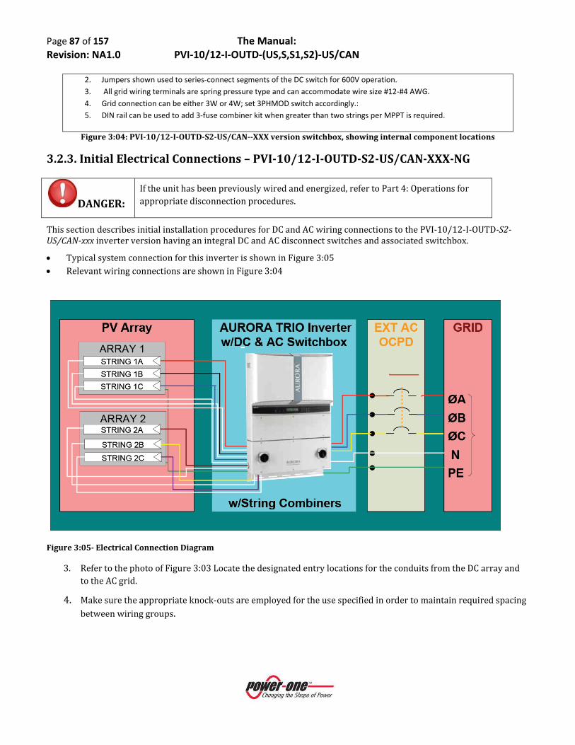
Page 87 of 157 The Manual: Revision: NA1.0 PVI-10/12-I-OUTD-(US,S,S1,S2)-US/CAN
2. Jumpers shown used to series-connect segments of the DC switch for 600V operation. 3. All grid wiring terminals are spring pressure type and can accommodate wire size #12-#4 AWG. 4. Grid connection can be either 3W or 4W; set 3PHMOD switch accordingly.: 5. DIN rail can be used to add 3-fuse combiner kit when greater than two strings per MPPT is required.
Figure 3:04: PVI-10/12-I-OUTD-S2-US/CAN--XXX version switchbox, showing internal component locations
3.2.3. Initial Electrical Connections – PVI-10/12-I-OUTD-S2-US/CAN-XXX-NG
DANGER: If the unit has been previously wired and energized, refer to Part 4: Operations for appropriate disconnection procedures.
This section describes initial installation procedures for DC and AC wiring connections to the PVI-10/12-I-OUTD-S2-US/CAN-xxx inverter version having an integral DC and AC disconnect switches and associated switchbox.
• Typical system connection for this inverter is shown in Figure 3:05 • Relevant wiring connections are shown in Figure 3:04
Figure 3:05- Electrical Connection Diagram
3. Refer to the photo of Figure 3:03 Locate the designated entry locations for the conduits from the DC array and to the AC grid.
4. Make sure the appropriate knock-outs are employed for the use specified in order to maintain required spacing between wiring groups.

Page 88 of 157 The Manual: Revision: NA1.0 PVI-10/12-I-OUTD-(US,S,S1,S2)-US/CAN
3.2.4 DC Array Connections
WARNING:
• Before attempting to connect the array wiring be certain the array sizing has been completed to the specific plan associated with the system being installed.
• To eliminate the potential for shock hazard during the connection procedure for the PV array wiring, either “open-circuit” all PV circuits prior to entry to the inverter and/or cover all panels with dark or opaque material in order to eliminate hazardous voltage at the terminals of the array wiring.
Figure 3:06- DC Array Connection
• Refer to Figure 3:06. Locate the incoming DC array wiring at the switchbox chassis and measure the voltage to ensure the array output is non-hazardous.
• Once de-energized, connect the DC wiring to the MPPT1 and MPPT2 array terminals shown in inverter per the specific array design.
• If the array is wired for dual MPPT mode, run separate wires for POS and NEG for each array and ensure no jumpers are installed between the two inputs See section on Signal Wiring below for more information.
Location Code
Details
A DC Array conduit entry
(KOs, 3 places)
KO for ¾” and 1”
trade size
D Array PE Ground Note 1
E DC Switch
+IN1 DC Array MPPT 1
F1, F2, F3
Note 2
-IN1 DC Array MPPT 1
NEG Returns Note 1
+IN2 DC Array MPPT 2
F4, F5, F6 Note 1
-IN2 DC Array MPPT 1
NEG Returns Note 1
Notes:
1. All array wiring terminal blocks are spring pressure type and accommodate a wire size range of #20-#6 AWG.
2. Fuse holders F1-F6 have screw terminals and tightening torque depends on wire size and type. See legend on fuseholder for details
3. Bus bar Terminals BT1, BT3, BT4, BT6 are used for various input wiring configurations.

Page 89 of 157 The Manual: Revision: NA1.0 PVI-10/12-I-OUTD-(US,S,S1,S2)-US/CAN
• If the array is designed for the parallel MPPT input mode, ensure the jumpers shown in Figure 3:12 are in place.
• Ensure the MPPT mode switch is in the correct position to match the array design.
3.2.5 AC Grid Connections
Figure 3:07 AC Grid Connections
• Refer to Figure 3:07. Locate the AC grid wiring at the inverter switchbox. Measure the voltage to ensure all connections to the grid have been eliminated and no hazardous voltage is present.
• Once de-energized, connect the AC wiring to the AC grid terminals. e. If the grid connection is to be 3W, the Neutral conductor does not need to be pulled or connected.
Place the 3PHMOD switch in the 3W position. f. If the grid connection is to be 4W, the Neutral connection must be provisioned and connected to
the Neutral terminal. Place the 3PHMOD switch in the 4W position.
3.2.6 Signal Wiring Connections –PVI-10/12-I-OUTD-S2-US/CAN-XXX-NG
WARNING: When operating in PAR mode the input terminals in the switchbox must also be wired in parallel to ensure current through switch is equalized.
Location Code
Details
G Main Ground Note 1
AC Grid Output Terminals
1, 2, 3, N Note 1,2
S AC Grid Disconnect switch 3ø/4wire
Notes:
1. All grid wiring terminals are spring pressure type and can accommodate wire size #12-#4 AWG.
2. Grid connection can be either 3W or 4W; 3PHMOD switch must be set accordingly.

Page 90 of 157 The Manual: Revision: NA1.0 PVI-10/12-I-OUTD-(US,S,S1,S2)-US/CAN
Figure 3:08 Signal Wire Routing
• Route the cables through the switchbox and into the inverter chassis using plastic guide (item K, Figure
3:08). • Refer to Figure 3:03. Note the position where the monitoring and alarm cables (if used) enter the
chassis. • Refer to Figure 3:09. Locate the terminals for the alarm and monitoring connections within the chassis. • Connect alarm cable to the mating connector (in hardware kit) and plug connector into position shown
in Figure 3:04 • Connect RS485 monitoring cable:
a). If using CAT5 cable for monitoring connections, connect RJ45 plug to end of cable as shown in Table 3, and plug into RJ45 jack shown in Table 03. A second jack is available to accommodate daisy chaining of communication line to other inverters.
b). If using standard multi-wire cable locate the mating connector (hardware bag) and connect the three RS-485 leads. Plug connector into position shown in Table 03; second connector is to facilitate daisy chaining. See Table 03 and Figure 2:09 or refer to the multi-system wiring section. c). Refer to section 04 for details to set RS485 address
Code Details
J RS485 Cable conduit entry (KOs) ½” trade size
K Plastic conduit for signal cables
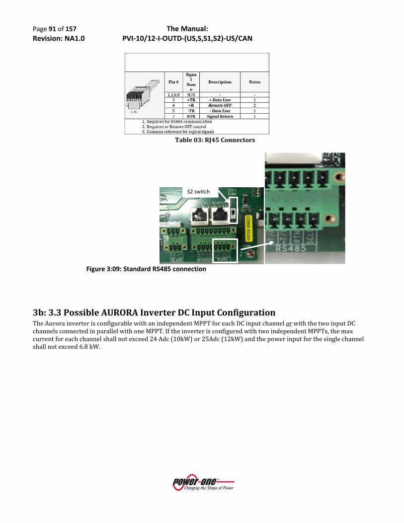
Page 91 of 157 The Manual: Revision: NA1.0 PVI-10/12-I-OUTD-(US,S,S1,S2)-US/CAN
Table 03: RJ45 Connectors
Figure 3:09: Standard RS485 connection
3b: 3.3 Possible AURORA Inverter DC Input Configuration The Aurora inverter is configurable with an independent MPPT for each DC input channel or with the two input DC channels connected in parallel with one MPPT. If the inverter is configured with two independent MPPTs, the max current for each channel shall not exceed 24 Adc (10kW) or 25Adc (12kW) and the power input for the single channel shall not exceed 6.8 kW.
S2 switch

Page 92 of 157 The Manual: Revision: NA1.0 PVI-10/12-I-OUTD-(US,S,S1,S2)-US/CAN
Figure 2:10: Configuration Settings
COUNTRY CODE SELECTOR 3-PHMOD SWITCH PAR/IND INMODE SWITCH
3.3.1 Selecting The Country Code
Figure 3:11- Selector Switches for choice of Country Code
1:
3W-Δ
4W-Y
3:
PAR
IND
2:
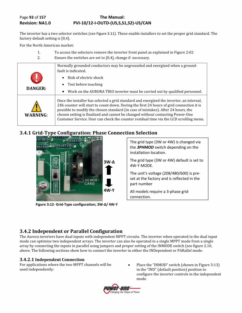
Page 93 of 157 The Manual: Revision: NA1.0 PVI-10/12-I-OUTD-(US,S,S1,S2)-US/CAN
The inverter has a two selector switches (see Figure 3:11). These enable installers to set the proper grid standard. The factory default setting is [0,4].
For the North American market:
1. To access the selectors remove the inverter front panel as explained in Figure 2:02 2. Ensure the switches are set to [0,4], change if necessary.
DANGER:
Normally grounded conductors may be ungrounded and energized when a ground-fault is indicated.
• Risk of electric shock
• Test before touching
• Work on the AURORA TRIO inverter must be carried out by qualified personnel.
WARNING:
Once the installer has selected a grid standard and energized the inverter, an internal, 24h counter will start to count down. During the first 24 hours of grid connection it is possible to modify the chosen standard (in case of mistakes). After 24 hours, the chosen setting is finalized and cannot be changed without contacting Power-One Customer Service. User can check the counter residual time via the LCD scrolling menu.
3.4.1 Grid-Type Configuration: Phase Connection Selection
Figure 3:12- Grid-Type configuration; 3W-Δ/ 4W-Y
3.4.2 Independent or Parallel Configuration The Aurora inverters have dual inputs with independent MPPT circuits. The inverter when operated in the dual input mode can optimize two independent arrays. The inverter can also be operated in a single MPPT mode from a single array by connecting the inputs in parallel using jumpers and proper setting of the INMODE switch (see figure 2.10, above. The following sections show how to connect the inverter in either the INDependent or PARallel mode.
3.4.2.1 Independent Connection For applications where the two MPPT channels will be used independently:
• Place the “INMOD” switch (shown in Figure 3:13) in the “IND” (default position) position to configure the inverter controls in the independent mode.
3W-Δ
4W-Y
The grid type (3W or 4W) is changed via the 3PHMOD switch depending on the installation location.
The grid type (3W or 4W) default is set to 4W-Y MODE.
The unit’s voltage (208/480/600) is pre-set at the factory and is reflected in the part number
All models require a 3-phase grid connection.

Page 94 of 157 The Manual: Revision: NA1.0 PVI-10/12-I-OUTD-(US,S,S1,S2)-US/CAN
• Ensure the parallel jumpers shown in Figure 3:14b, are not present.
• After switching the AURORA TRIO Inverter to independent mode configuration, re-install the front panel (apply 13.2 in-lbs of torque to each of the 6 screws).
Figure 3:13- INDependent mode switch configuration Switch
3.4.2.2 Parallel Connection To operate the inverter in the single MPPT mode:
• Place the INMODE switch (shown in Figure 3:14a) in the “PAR” position to configure the inverter controls in parallel mode.
• Connect bus bar terminals BT3 and BT4 together via a short #8AWG jumper
• Connect terminal blocks -IN1 and -IN2 return terminals together using terminal block jumpers found in hardware bag.
• Upon completion, re-install the front panel (apply 13.2 in-lbs of torque to each of the 6 screws).
Figure 3:14a: Parallel Mode Configuration Switch
IND
PAR

Page 95 of 157 The Manual: Revision: NA1.0 PVI-10/12-I-OUTD-(US,S,S1,S2)-US/CAN
MPPT#1T1+ T2+
Switch Box Chassis
10kW/12kW [-S or -S2] DC Wiring – POS Ground Version –
PARallel mode onlyWith 2x3 String Fuse Combiner
Capable of landing 6 StringsAdd #8AWG wire jumper between busbars
Add terminal block jumper to RTN terminal blocks
MPPT#2 T1-
Inverter Chassis
DC Switch
-IN2-IN1 -IN1 -IN2
Bus bar assy 1 Bus bar assy 2
-------[-IN1]-------F1 F2 F3
-------[-IN2]-------F4 F5 F6
T2- T2- T1+ T1- T2+
+IN2 +IN2+IN1 +IN1
1- 2- 3- | 4- 5- 6-MPPT #1 | MPPT #2
NEG Fused
| 1-3 | 4-6 | | POS String | | Returns |
Figure 3:14b: Jumpers installed for Parallel MPPT Input Connection
Page 96 of 157 The Manual: Revision: NA1.0 PVI-10/12-I-OUTD-(US,S,S1,S2)-US/CAN
SECTION 4: WIRING DETAILS
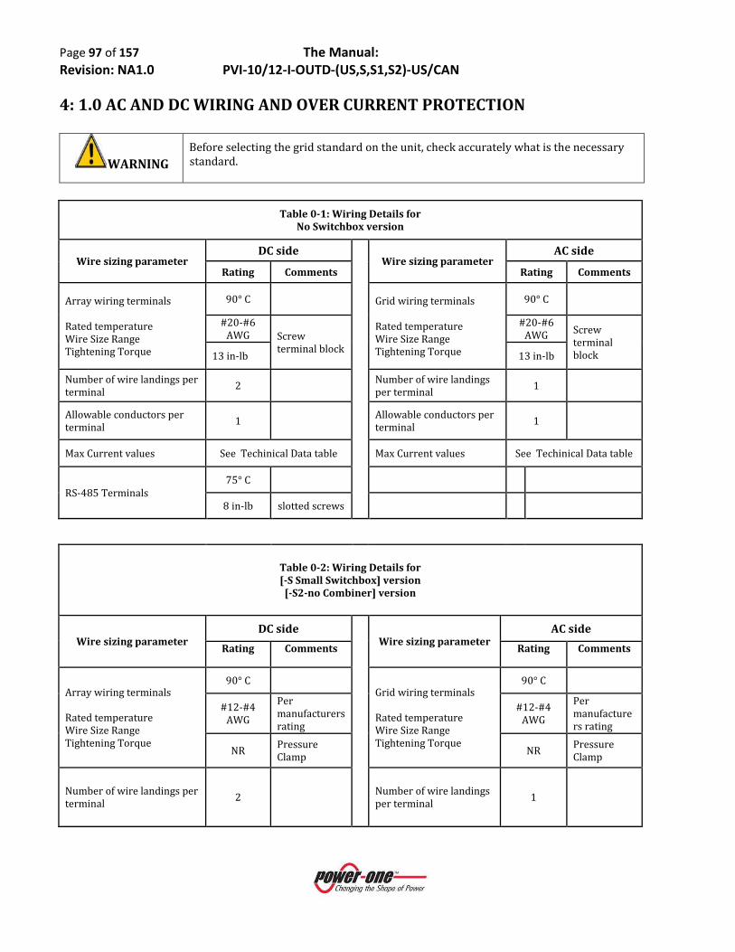
Page 97 of 157 The Manual: Revision: NA1.0 PVI-10/12-I-OUTD-(US,S,S1,S2)-US/CAN
4: 1.0 AC AND DC WIRING AND OVER CURRENT PROTECTION
WARNING Before selecting the grid standard on the unit, check accurately what is the necessary standard.
Table 0-1: Wiring Details for
No Switchbox version
Wire sizing parameter DC side
Wire sizing parameter AC side
Rating Comments Rating Comments
Array wiring terminals Rated temperature Wire Size Range Tightening Torque
90° C Grid wiring terminals Rated temperature Wire Size Range Tightening Torque
90° C
#20-#6 AWG Screw
terminal block
#20-#6 AWG Screw
terminal block 13 in-lb 13 in-lb
Number of wire landings per terminal 2 Number of wire landings
per terminal 1
Allowable conductors per terminal 1 Allowable conductors per
terminal 1
Max Current values See Techinical Data table Max Current values See Techinical Data table
RS-485 Terminals 75° C
8 in-lb slotted screws
Table 0-2: Wiring Details for [-S Small Switchbox] version [-S2-no Combiner] version
Wire sizing parameter DC side
Wire sizing parameter AC side
Rating Comments Rating Comments
Array wiring terminals Rated temperature Wire Size Range Tightening Torque
90° C Grid wiring terminals Rated temperature Wire Size Range Tightening Torque
90° C
#12-#4 AWG
Per manufacturers rating
#12-#4 AWG
Per manufacturers rating
NR Pressure Clamp NR Pressure
Clamp
Number of wire landings per terminal 2 Number of wire landings
per terminal 1

Page 98 of 157 The Manual: Revision: NA1.0 PVI-10/12-I-OUTD-(US,S,S1,S2)-US/CAN
Allowable conductors per terminal 1 Allowable conductors per
terminal 1
Max Current values See Techinical Data table Max Current values See Techinical Data table
RS-485 Terminals 75° C
8 in-lb slotted screws
Table 0-3: Wiring Details for
[-S1 Large Switchbox] version [-S2-with Combiner] version
Wire sizing parameter DC side
Wire sizing parameter AC side
Rating Comments Rating Comments
Array wiring terminals Rated temperature Wire Size Range Tightening Torque
90° C Array wiring terminals Rated temperature Wire Size Range Tightening Torque
90° C
#12-#4 AWG
Per mfr’s rating
#12-#4 AWG
Per manufacturers rating
N/A in-lb
Pressure Clamp N/A in-lb Pressure
Clamp
Number of wire landings per terminal 2 Number of wire landings
per terminal 1
Allowable conductors per terminal 1 Allowable conductors
per terminal 1
Max Current values See Techinical Data table Max Current values See Techinical Data table
RS-485 Terminals 75° C
RS-485 Terminals 75° C
8 in-lb slotted screws 8 in-lb slotted
screws

Page 99 of 157 The Manual: Revision: NA1.0 PVI-10/12-I-OUTD-(US,S,S1,S2)-US/CAN
4.1.2 Fused Combiners and Array Connections
The [-S/S1] and [-S2] models are provisioned with two 3-input fused combiner blocks consisting of three fuse holders bused to each MPPT input channel. The two combiners can be used independently for the IND mode, or they can be paralleled by use of jumpers for the PAR mode. Figures 1 and 2 below show wiring and necessary jumpers for typical [-NG] and [-PG] configurations. Note that the positive ground version can only be operated in the PARallel input mode configurations.
MPPT#1T1+ T2+
Switch Box Chassis
Proposed 10kW/12kW [-S2] DC Wiring (NOV2011)– NEG Ground Version –
With 2x3 String Fuse Combiner Capable of landing 6 Strings IND or PAR mode
Extra bus bar terminals for jumpers and/or terminations
Original 2:1 terminal blocks relocated and rewired to use for string return circuit
MPPT#2T2+ T1-
Inverter Chassis
DC Switch
-IN2-IN1 -IN1 -IN2
Bus bar assy 1 Bus bar assy 2
-------[+IN1]-------F1 F2 F3
-------[+IN2]-------F4 F5 F6
T2- T2- T1+ T1-
-IN2 -IN2-IN1 -IN1
1+ 2+ 3+ | 4+ 5+ 6+MPPT #1 | MPPT #2
POS Fused
| 1-3 | 4-6 | | NEG String | | Returns |
Figure 1: Hardware and connections for [-NG] inverter connection
MPPT#1T1+ T2+
Switch Box Chassis
10kW/12kW [-S or -S2] DC Wiring – POS Ground Version –
PARallel mode onlyWith 2x3 String Fuse Combiner
Capable of landing 6 StringsAdd #8AWG wire jumper between busbars
Add terminal block jumper to RTN terminal blocks
MPPT#2 T1-
Inverter Chassis
DC Switch
-IN2-IN1 -IN1 -IN2
Bus bar assy 1 Bus bar assy 2
-------[-IN1]-------F1 F2 F3
-------[-IN2]-------F4 F5 F6
T2- T2- T1+ T1- T2+
+IN2 +IN2+IN1 +IN1
1- 2- 3- | 4- 5- 6-MPPT #1 | MPPT #2
NEG Fused
| 1-3 | 4-6 | | POS String | | Returns |
Figure 2: Hardware and connections for [-PG] inverter connection
The following figures detail various allowable string configurations based the switch box hardware.

Page 100 of 157 The Manual: Revision: NA1.0 PVI-10/12-I-OUTD-(US,S,S1,S2)-US/CAN
MPPT#1T1+ T2+
Switch Box Chassis
10kW/12kW DC Wiring (NOV2011)– NEG Ground Version –
With 2x3 String Fuse Combiner Capable of landing 3 Strings per MPPT (IND mode)
MPPT#2T2+ T1-
Inverter Chassis
DC Switch
Bus bar assy 1 Bus bar assy 2
-------[+IN1]-------F1 F2 F3
-------[+IN2]-------F4 F5 F6
T2- T2- T1+ T1-
1+ 2+ 3+ | 4+ 5+ 6+MPPT #1 | MPPT #2
-IN2 -IN2-IN1 -IN1
| 1-3 | 4-6 | | NEG String | | Returns |
Scenario #3: In-switchbox combining (dual 3-string configuration) up to six strings using dual (IND) MPPT Configuration

Page 101 of 157 The Manual: Revision: NA1.0 PVI-10/12-I-OUTD-(US,S,S1,S2)-US/CAN
MPPT#1T1+ T2+
Switch Box Chassis
10kW/12kW DC Wiring (NOV2011)– NEG Ground Version –
With 1x6 String Fuse Combiner Land up to 6 Strings to Single MPPT (PAR mode)
Add #8 solid Cu jumpers to bus bar as notedAdd terminal block jumper to return TB as shown
MPPT#2T2+ T1-
Inverter Chassis
DC Switch
-IN2-IN1 -IN1 -IN2
Bus bar assy 1 Bus bar assy 2
-------[+IN1]-------F1 F2 F3
-------[+IN2]-------F4 F5 F6
T2- T2- T1+ T1-
1+ 2+ 3+ | 4+ 5+ 6+Parallel MPPT
-IN2 -IN2-IN1 -IN1
| 1-3 | 4-6 | | NEG String | | Returns |
Scenario #4: In-switchbox combining (6x1) up to six strings using single (PAR) MPPT Configuration (requires bus bar jumper and single terminal block jumper)

Page 102 of 157 The Manual: Revision: NA1.0 PVI-10/12-I-OUTD-(US,S,S1,S2)-US/CAN
MPPT#1T1+ T2+
Switch Box Chassis
10kW/12kW DC Wiring (NOV2011)– NEG Ground Version –
With 2x3 String Fuse Combiner Connections for Dual MPPT mode w/external combining
Use Sub-feed lugs for POS leadsAdd two terminal block jumpers on RTN TBs as shown
MPPT#2T2+
Inverter Chassis
DC Switch
Bus bar assy 1 Bus bar assy 2
-------[+IN1]-------F1 F2 F3
-------[+IN2]-------F4 F5 F6
T2- T2- T1+ T1-
1+ | 2+ Dual MPPT
-IN2 -IN2-IN1 -IN1
T1-
| 1- | 2- | | NEG String | | Returns |
Scenario #5: External combining of up to six strings using dual (IND) MPPT Configuration (requires two terminal block jumpers)

Page 103 of 157 The Manual: Revision: NA1.0 PVI-10/12-I-OUTD-(US,S,S1,S2)-US/CAN
MPPT#1T1+ T2+
Switch Box Chassis
10kW/12kW DC Wiring (OCT2011)– NEG Ground Version –
With 2x3 String Fuse Combiner Connections for PAR MPPT mode w/external combining
Fuses not utilized Use sub-feed terminal on bus bar to connect arrays
Add #8 solid Cu jumper between bus barsAdd a single terminal block jumper on RTN TBs as shown
MPPT#2T2+
Inverter Chassis
DC Switch
Bus bar assy 1 Bus bar assy 2
-------[+IN1]-------F1 F2 F3
-------[+IN2]-------F4 F5 F6
T2- T2- T1+ T1-
Single MPPT External Feed
String Return
-IN2 -IN2-IN1 -IN1
T1-
Scenario #6: External combining of up to six strings using single (PAR) MPPT Configuration (Requires busbar jumper and one terminal block jumper)
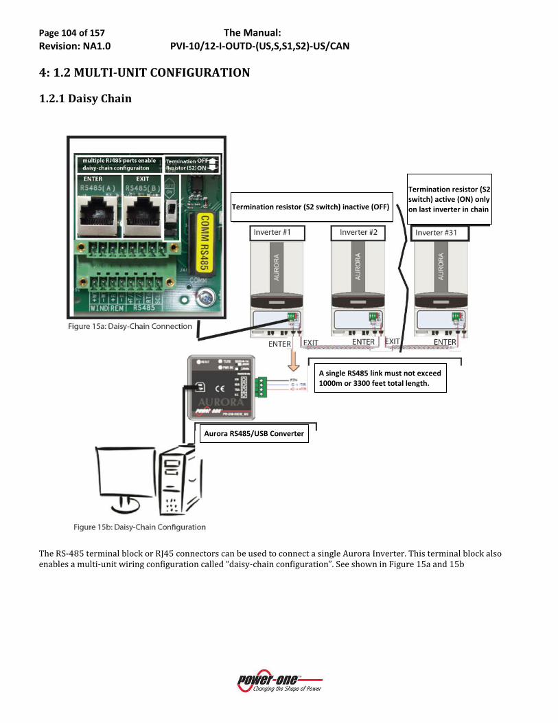
Page 104 of 157 The Manual: Revision: NA1.0 PVI-10/12-I-OUTD-(US,S,S1,S2)-US/CAN
4: 1.2 MULTI-UNIT CONFIGURATION
1.2.1 Daisy Chain
The RS-485 terminal block or RJ45 connectors can be used to connect a single Aurora Inverter. This terminal block also enables a multi-unit wiring configuration called “daisy-chain configuration”. See shown in Figure 15a and 15b
Termination resistor (S2 switch) active (ON) only on last inverter in chain
Aurora RS485/USB Converter
A single RS485 link must not exceed 1000m or 3300 feet total length.
Termination resistor (S2 switch) inactive (OFF)
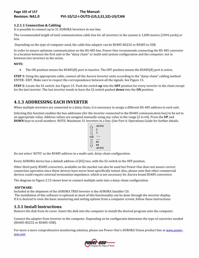
Page 105 of 157 The Manual: Revision: NA1.0 PVI-10/12-I-OUTD-(US,S,S1,S2)-US/CAN
1.2.1.1 Connection & Cabling It is possible to connect up to 31 AURORA Inverters in one line.
The recommended length of total communication cable line for all inverters in the system is 1,000 meters [1094 yards] or less.
Depending on the type of computer used, the cable line adaptor can be RS485-RS232 or RS485 to USB.
In order to ensure optimum communication on the RS-485 line, Power-One recommends connecting the RS-485 converter to a location between the first unit in the “daisy chain” or multi-unit system configuration and the computer; not in between two inverters in the series.
NOTE:
• The ON position means the RS485(B) port in inactive. The OFF position means the RS485(B) port is active.
STEP 1: Using the appropriate cable, connect all the Aurora Inverter units according to the “daisy-chain” cabling method ENTER- EXIT. Make sure to respect the correspondence between all the signals. See Figure 15.
STEP 2: Locate the S2 switch. See Figure 15. Push the switch up into the OFF position for every inverter in the chain except for the last inverter. The last inverter needs to have the S2 switch pushed down into the ON position.
4.1.3 ADDRESSING EACH INVERTER When multiple inverters are connected in a daisy chain, it is necessary to assign a different RS-485 address to each unit.
Selecting this function enables the bus addresses (for the inverter connected to the RS485 communication bus) to be set to an appropriate value. Address values are assigned manually using any value in the range [2 to 64]. Press the UP and DOWN keys to scroll numbers. NOTE: Maximum 31 inverters in a line. (See Part 4: Operations Guide for further details.
AUTO 2 3 ….. ….. 63 64 AUTO
Do not select ‘AUTO’ as the RS485 address in a multi-unit, daisy-chain configuration. Every AURORA device has a default address of [02] two, with the S2 switch in the OFF position.
Other third party RS485 converters, available on the market can also be used but Power-One does not assure correct connection operation since these devices have never been specifically tested. Also, please note that other commercial devices could require external termination impedance, which is not necessary for Aurora brand RS485 converters.
The diagram in Figure 2:15 shows how to connect multiple units into a daisy-chain configuration. SOFTWARE: Included in the shipment of the AURORA TRIO Inverter is the AURORA Installer CD. The installation of this software is optional as most of this functionality can be done through the inverter display. If it is desired to view the basic monitoring and setting options from a computer screen, follow these instructions:
1.3.1 Install Instructions: Remove the disk from its cover. Insert the disk into the computer to install the desired program onto the computer. Connect the adapter from Inverter to the computer. Depending on he configuratin determine the type of converter needed (RS485-RS232 or RS485-USB). For more a more comprehensive monitoring solution, please see Power-One’s AURORA Vision product line at www.power-one.com
Page 106 of 157 The Manual: Revision: NA1.0 PVI-10/12-I-OUTD-(US,S,S1,S2)-US/CAN
PART 4: OPERATIONS GUIDE

Page 107 of 157 The Manual: Revision: NA1.0 PVI-10/12-I-OUTD-(US,S,S1,S2)-US/CAN
4: 0.1 COMMISSIONING The procedure for commissioning AURORA TRIO Inverter is as follows:
1) Set the inverter's DC disconnect switch (external or part of switchbox version) to ON.
2) Set the AC disconnect switch (external or part of switchbox depending on version) to the inverter to ON.
NOTE: There is no specific order for closing the two switches.
3) Once both switches are closed, the inverter starts the grid connection sequence. This routine is indicated by the flashing green LED labelled POWER over the display.
This routine may take from 30 seconds up to several minutes, depending on grid condition. Three screens are shown in sequence on the LCD display during this routine:
• Grid voltage value and status compared to specified values (within/outside range).
• Grid frequency value and status compared to specified values (within/outside range).
4) When the connection sequence is completed the AURORA Inverter starts operating. Proper operation is indicated by a warning sound and the green LED lights steadily green.
5) If the grid check routine does not give a positive result, the unit will repeat the procedure until all grid voltage; frequency parameters and grid configuration are found or changed to be within the specified range. During this process, the green LED will keep flashing.
4.1.0 INVERTER START-UP and OPERATION
WARNING
• Do not place any items on the AURORA TRIO Inverter during operation.
• Do not touch the heat sink when the inverter is operating, as some parts may be hot and cause burns.

Page 108 of 157 The Manual: Revision: NA1.0 PVI-10/12-I-OUTD-(US,S,S1,S2)-US/CAN
1.1 NORMAL START- UP PROCEDURE
The green ‘Power’ LED indicates that the ARUROA Inverter is operating correctly.
The yellow ‘FAULT’ LED indicates that the AURORA Inverter has detected a fault condition. A fault description will appear on the display. See troubleshooting section of this manual or contact Power-One Technical Support.
Red GFI Ground Fault on the DC side of the system. Press ESC to restart See troubleshooting section to help or contact Power-One Technical Support.
Missing Grid
Waiting Sun…
Initializing stops until grid is found or settings are changed to match voltage. Possible error codes: W007: Grid Under Frequency W006: Grid Over Frequency W005: Output Under Voltage W004: Output Over Voltage
If DC = > 200V If DC = < 200V
Inverter is waiting for the sun/wind. Possible error codes: E002: Input Under Voltage W011: Sun Low E013: Wrong Mode (PAR/IND)
Ground Fault Fault Description
Unit cycles through various screens while connecting.
= Inverter OK. Cycles through Inverter statistics
= Error/Alert/Warning May see any of the remaining error codes
Power-One Initializing… Please wait…
Next connections… 2 sec

Page 109 of 157 The Manual: Revision: NA1.0 PVI-10/12-I-OUTD-(US,S,S1,S2)-US/CAN
Depending on the DC input voltage present, the inverter behaves as follows:
a) When the inverter is switched ON, it will start as soon as the input voltage value of 130 Vdc is reached.
b) The inverter will display the message 'Waiting Sun' until the input voltage exceeds the set Vin start value.
c) When the Vin start value is exceeded, the inverter will connect to the grid if it is identified or it will display the message ‘Vac absent’ if the grid is not connected.
d) The inverter will remain connected to the grid if the input voltage is between 70% of the Vin start set and 520 Vdc. If the input voltage value is outside this range, the inverter disconnects itself from the grid.
1.2 START-UP USING SIDE BUTTON When no DC array voltage is available (night) at the input, if the AC is properly connected and present, user can turn on the inverter using an internal standby supply by pressing the side key shown in figure 4:01, for more than 2 seconds. An audible “beep” will indicate the detection of pressed key from the inverter. The key is located on the right side of the inverter.
The inverter will stay on for 10 minutes enabling every type of control on the display (statistics, settings etc.); however, the inverter will not connect to the grid unless a valid DC input is applied.
If turned ON with no DC voltage the inverter will use energy from the grid to stay on (less than 20W).
Figure 4:01- Inverter Stand-by Supply Button

Page 110 of 157 The Manual: Revision: NA1.0 PVI-10/12-I-OUTD-(US,S,S1,S2)-US/CAN
1.3 SHUT-DOWN PROCEDURE There are three options for shutting down the inverter:
1) Disconnect the DC and the AC grid, by disconnecting its associated switches (in any order). The inverter will shut down within a few seconds necessary to discharge the internal capacitors.
2) Disconnect the DC input by turning-off the associated disconnect switch and waiting for the UV port time out
3) Disconnect the grid, by turning-off its associated disconnect switch and reduce DC input to less than 130 Vdc.
1.4 POWER-DOWN PROCEDURES Once the inverter is wired and connected to the grid use the following procedures to disconnect for maintenance
WARNING Before performing any operation on the switcbox power input, ALWAYS perform the appropriate disconnection procedure outlined below.
1.4.1 Disconnection Of Aurora Inverters
Figure 4:02: Location of Front Access Panels
Inverter cover: Torx 20, Screw, 6pl
Captive screws X6

Page 111 of 157 The Manual: Revision: NA1.0 PVI-10/12-I-OUTD-(US,S,S1,S2)-US/CAN
Location
Code Details
Location Code
Details
A DC Array conduit entry
(KOs, 3 places) Note 1 F
AC grid conduit
entry (4 places) Note 1
D Array PE Ground Note 2 G Main Ground Note 4
E DC Switch AC Grid Output Terminals 1, 2, 3, N Note 4,5
+IN1 DC Array MPPT 1:F1, F2, F3 Note 3 S AC Grid Disconnect switch 3ø/4wire
-IN1 DC Array MPPT 1: NEG Returns Note 2 J RS485 cable conduit entry ½” trade size
KO
+IN2 DC Array MPPT 2: F4, F5, F6 Note 3 K Plastic conduit to segregate signal cables
-IN2 DC Array MPPT 1: NEG Returns Note 2 BTx Busbar Terminals 1, 2, 3, 4 Note 4

Page 112 of 157 The Manual: Revision: NA1.0 PVI-10/12-I-OUTD-(US,S,S1,S2)-US/CAN
Notes:
1. KOs for ¾” and 1” trade size 2. All array wiring terminals are spring pressure type and can accommodate a wire size range of #20-#6 AWG. 3. Fuse holders F1-F6 have screw terminals. Wire size and torque level depends on wire type and size - see
fuseholder legend. 4. All grid wiring terminals are spring pressure type and can accommodate wire size #12-#4 AWG. 5. Grid connection can be either 3W or 4W; set 3PHMOD switch accordingly. 6. KOs for 1/2” trade size
Figure 4:03: PVI-10/12-I-OUTD-US /CAN-Wiring Connection Details
Refer to Figure 4:03 Wiring Connection Details for the following procedure:
Step 1: Disconnect from the AC Grid by one of the following methods: a. Turn-off the external AC switch b. Turn-off the Over Current Protection Device (circuit breaker)
Step 2: Disconnect the inverter from the PV array by turning off the external DC disconnect switch connect the DC cable to the terminal block on the PCB. Be sure respecting marking (+In1, -In1, +In2, -In2) and carefully check the correct polarity of the DC cable.
Step 3: Remove the inverter cover seem ( Figure 4:02). Using a voltmeter, check voltage levels at the DC input terminals and the AC output cables to ensure no hazardous voltages are present.
4: 2.0 OPERATIONS: USER INTERFACE, MONITORING AND DATA TRANSMISSION 2.1 USER INTERFACE MODE Normally, the AURORA Trio operates automatically and needs no particular supervision. When solar radiation is not enough to generate power for the grid (for example: at night), AURORA Inverter disconnects automatically and goes into a standby mode.
The operating cycle resumes automatically when sufficient sunlight becomes available.
The AURORA Trio provides operational data to the operator through the following instruments:
● LED Indicator lights
● LCD display
● Digital data transmission is via a dedicated RS-485 serial port using Aurora Protocol and a PC or a data logger equipped with an RS-485 port collects data. If an RS-485 line is used, it may be convenient to use the AURORA USB/RS-485_232 serial interface converter (model number PVI-USB-RS485_232). The optional AURORA PVI-UNIVERSAL data logger is also available, which allows a web-based monitoring platform.

Page 113 of 157 The Manual: Revision: NA1.0 PVI-10/12-I-OUTD-(US,S,S1,S2)-US/CAN
Figure 04:4- Data Transmission Options
2.2 DATA TYPES AVAILABLE AURORA Inverter provides two types of data that can be collected using the display and/or the appropriate interface software.
2.2.1 Real-Time Operational Data Real-time operational data can be transmitted on demand through the communication lines and are not stored inside the inverter. The free AURORA Communicator software (included on the installation CD) may be used to transmit data to a PC. Please check the Power-One website at www.power-one.com for the latest updated version.
The following data is available via the RS-485 link:
● Grid voltage ● Grid current ● Grid frequency ● Power transferred to the grid ● Voltage of photovoltaic array 1 ● Current of photovoltaic array 1 ● Voltage of photovoltaic array 2 ● Current of photovoltaic array 2 ● Serial Number/Code ● Week of production
● Firmware revision code ● Daily energy ● Leakage current of the system ● Total energy ● Partial energy ● Mean grid voltage ● Insulation resistance ● Leakage current to ground ● Date, time
2.2.2 Data Logged Internally Power-One’s AURORA Vision stores the following data internally:
Total and partial counter of grid connection time.
Total and partial counter of energy transferred to the grid.
Daily Energy Production (365 values).

Page 114 of 157 The Manual: Revision: NA1.0 PVI-10/12-I-OUTD-(US,S,S1,S2)-US/CAN
Energy transferred to the grid every 10 seconds for the last 8,640 periods of 10 seconds (which on average cover more than 2 days of logged data).
Last 100 fault conditions with error code and time stamp.
Last 100 changes to grid connection parameters with parameter code and new value.
The first two types of data are displayed on the LCD display and through the RS-485 interface, while all other data can be displayed only through the RS-485 interface.
2.3 LED INDICATORS
Figure 4:05: Location of the buttons and LEDs
There are three LEDs on the left side of the display:
1. The green 'Power' LED indicates that AURORA Inverter is operating correctly.
This LED flashes upon start-up, during the grid check routine. If a correct grid voltage is detected and solar radiation is strong enough to start-up the unit, the LED stays on steady. If not, the LED keeps flashing until solar radiation becomes strong enough to start-up the inverter. In this condition, the display will read 'Waiting Sun….'
2. The yellow 'FAULT' LED indicates that the Aurora inverter has detected a fault condition. A fault description will appear on the display.
3. The red 'GFI' (ground fault) LED indicates that AURORA Inverter is detecting a ground fault in the DC side of the photovoltaic system. When this kind of fault is detected, the AURORA inverter disconnects from the grid and the corresponding fault indication appears on the LCD display. AURORA Inverter remains in this condition until the operator presses the ESC key to re-start the grid connection sequence. If pressing the ESC key doesn’t clear the ground fault check the ground-fault, fuse located in the switchbox. If AURORA Inverter does not reconnect to the grid, contact Power-One Technical Service.
DANGER:
Normally grounded conductors may be ungrounded and energized when a ground-fault is indicated.
• Risk of electric shock
• Test before touching
• Work on the AURORA TRIO inverter must be carried out by qualified personnel.
The following table shows all the possible LED-signalling indications related to the operational status of AURORA Inverter.
Key:
LED on LED flashing

Page 115 of 157 The Manual: Revision: NA1.0 PVI-10/12-I-OUTD-(US,S,S1,S2)-US/CAN
LED off
Any of the above conditions
NOTE: Inverter status is indicated by the corresponding LED turning to a steady ON-condition or flashing, and by a message on the AURORA LCD displaying a description of the existing operation or fault condition (see the
following sections).
2.4 MESSAGES AND ERROR CODES
DANGER:
Normally grounded conductors may be ungrounded and energized when a ground-fault is indicated.
• Risk of electric shock
• Test before touching
• Work on the AURORA TRIO inverter must be carried out by qualified personnel.
The system status is identified through message or error signals displayed on the LCD display. The following tables briefly describe the two types of signals which may be displayed.
• MESSAGES identify the current status AURORA TRIO inverter status. Messages do not relate to a fault. When a (W) with a number after it appears in the display, it indicates a WARNING CODE and is usually cleared through an orderly shutdown/re-set or a self-corrective action performed by the inverter. See the (W) codes in the following table.
LED STATUS OPERATIONAL STATUS NOTES
1 1: green: 2: yellow: 3: red:
AURORA self-disconnects during night-time
Input voltage less than 90 Vdc at both inputs
2 1: green: 2: yellow: 3: red:
AURORA Inverter initialization, settings loading, and waiting for grid check
It is in transition status while operating conditions are being checked.
3 1: green: 2: yellow: 3: red:
AURORA Inverter is powering the grid
Standard machine operation (search for maximum power point or constant voltage)
4 1: green: 2: yellow: 3: red:
System insulation device faulty Leakage to ground found
5 1: green: 2: yellow: 3: red:
Defect – fault!!! The fault can be inside or outside the inverter. See the alarm appearing on the LCD display.
6 1: green: 2: yellow: 3: red:
Installation Phase: AURORA Inverter is disconnected from the grid.
During installation, it indicates set-up phase of the address for RS-485 communication.
7 1: green: 2: yellow: 3: red:
Grid disconnection Indicates a missing grid condition

Page 116 of 157 The Manual: Revision NA1.0 PVI-10/12-I-OUTD-(US,S,S1,S2)-US/CAN
• ALARMS or (E) codes identify a possible equipment failure, fault or incorrect inverter setting/ configuration. However, some of the (E) codes may require contacting Power-One Technical Support to assist in correcting a fault. Any and all attempts to correct or clear a fault must be performed by qualified personnel. Typically, the (E) can be cleared once the cause or fault is removed. Some of the (E) codes, (INT. Error) as indicated in the table below, may indicate a fatal error and require the support of Power-One Technical Support for diagnostics support. The appearance of an alarm signal will be managed as much as possible by AURORA Vision or, in case this is not possible, AURORA Vision will supply all the necessary information to perform the maintenance operations and to fix the fault on the equipment or system. See the (E) lines in the following table.
Message Error Warning
Error Type Description Message Error
Warning Error Type Description
Sun Low W001 // Input Voltage under Vstart threshold
Int.Error // E022 Autotest Timeout
Input OC // E001 Input Overcurrent Int.Error // E023 Dc-Injection Error Input UV W002 // Input Undervoltage Grid OV W004 // Output Overvoltage Input OV // E002 Input Overvoltage Grid UV W005 // Output Undervoltage Int.Error // E003 No parameters Grid OF W006 // Output Overfrequency Bulk OV // E004 Bulk Overvoltage Grid UF W007 // Output Underfrequency
Int.Error // E005 Communication Error
Z Grid HI W008 // Z grid out of range
Out OC // E006 Output Overcurrent Int.Error // E024 Unknown Error – Int.
Error // E007 IGBT Sat --------- // E025 Riso Low (Log Only)
Sun Low W011 // Bulk Undervoltage Int.Error // E026 Vref Error Int.Error // E009 Internal Error Int.Error // E027 Vgrid Measures Fault Grid Fail W003 // Grid Fail Int.Error // E028 Fgrid Measures Fault Int.Error // E010 Bulk Low Int.Error // E029 Zgrid Measures Fault Int.Error // E011 Ramp Fail
Over Temp. // E014 Overtemperature Int.Error // E030 Ileak Measures Fault
Cap. Fault // E015 Bulk Capacitor Fail Int.Error // E031 Wrong V Measure
DC/DC Fail // E012 DcDc Error revealed
by inverter Int.Error // E032 Wrong I Measure
Wrong Mode // E013
Wrong Input setting (Single instead of dual) or wrong grounding mode
Empty Table
W009 // No wind table (only wind -W versions)
Inv. Fail // E016 Inverter fail revealed by DcDc
Fan Fail W010 // Fan Fail (No disconnection)
Int.Error // E017 Start Timeout Int.Error // E033 UnderTemperature Ground
F. // E018 I leak fail // E034 Interlock Fail (Not Used)
Int.Error // E019 Ileak Sensor fail // E035 Remote Off Int.Error // E020 DcDc relay fail // E036 Vout Avg Error Int.Error // E021 Inverter relay fail W012 // Clock Battery Low (No
disconnection) W013 // Clock Failure (No
disconnection)
Table 4:01 Messages and Error Codes
2.5 LCD DISPLAY
2.5.1 Connection of the System to the Grid A two-line LCD display is located on the front panel. It shows the following:

Page 117 of 157 The Manual: Revision NA1.0 PVI-10/12-I-OUTD-(US,S,S1,S2)-US/CAN
Inverter operating status and statistics; Service messages for the operator; Alarm and fault messages. During regular operation, the display will cycle through available data. The display changes to a different screen every 5 seconds, or screens may be scrolled manually by pressing the UP (2nd key from display) and DOWN keys (3rd key from display).
Figure A- Display Key Operation
1) These two screens are displayed at inverter start-up:
2) The following screens may appear while waiting for the connection to be established:
- While the system checks for grid connection to be established ('Missing Grid'), the yellow LED next to the display turns on steady, while the green LED flashes.
- When waiting for solar radiation ('Waiting Sun'), the green LED turns on steady.
- As soon as the 'Missing Grid' and 'Waiting Sun' conditions are met successfully, the inverter is connected.
Waiting Sun Missing Grid
POWER-ONE Initializing… Please wait
A NOTE ON DISPLAY KEY OPERATION: During regular operation, the display will cycle through available data. The display changes to a different screen every 5 seconds, or screens may be scrolled manually by pressing the UP (2nd key from display) and DOWN keys (3rd key from display). To return to the preceding menu, press the ESC key (1st key from display).
Activation of cyclical scrolling is indicated by the 2 arrows in the top left corner of the display (Figure. A).
Scrolling can be blocked by pressing the ENTER key (4th key from display). A padlock symbol will appear (Figure. A).
Figure A

Page 118 of 157 The Manual: Revision NA1.0 PVI-10/12-I-OUTD-(US,S,S1,S2)-US/CAN
3) This display shows the time (seconds) remaining to complete the output voltage and frequency values check.
4) This display shows the instant output voltage value and whether it is within/outside range.
5) This displays the instant output frequency value and whether it is within/outside range.
6) If the measured instant values of voltage (point 4) and frequency (point 5) are outside the allowed range, the following screens are scrolled alternately:
Next connections (screen 3) → Vgrid (screen 4) →-Fgrid (screen 5)
2.5.2 Error Messages After the connection is established, the inverter runs a test cycle. If the wrong data is found, the cycle is interrupted and an error code is displayed. Please refer to Table 4:01 for error codes and their meanings.
To customize the message shown on the display, you must carry out the programming procedure described in Section 2.5.25, 'Alarm Message'. The system will continue to cycle through the following screens until the error has been rectified:
Once the error is cleared, the inverter resets all functions in progress and re-starts the connection (Section 1.2):
- Missing grid - Waiting sun
2.5.3 First Phase- Electric Parameter Check 1A) If the measurements taken previously (see section 2.1) are found to be correct, the system will proceed to the next checks. The 12 screens outlined below are shown alternately as listed in the Note A: 'A FEW POINTERS ON DISPLAY KEY OPERATION'.
2A) This display shows the inverter serial number and firmware revision level.
S/N--------- xxxxxx FW rel. C.0.1.1
Type OUTD PN------------
S/N ………..…….. Firmware…… In range
Custom msg……… Type OUTD Part No……… In range
ERROR Code ……..
Fgrid 60.17 Hz In range
Vgrid 223.8 V In range
Next connections: 2 secs

Page 119 of 157 The Manual: Revision NA1.0 PVI-10/12-I-OUTD-(US,S,S1,S2)-US/CAN
3A)
• E-da: Daily energy output. • $-da: Daily energy savings. The value is expressed in the set currency.
4A)
• E-tot: Total energy output (since first installation). • E-par : Partial energy output during the period selected by us.
5A)
P-out: Measures instant output power. The second line of the display shows the higher of the two temperatures:
• T-boost1: Booster channel 1 switching device temperature. • T-boost2: Booster channel 2 switching device temperature.
6A)
Ppk: Maximum peak power achieved since the 'partial' function was activated. Ppk-Day: Indicates the maximum peak power achieved during the day. The counter will reset when unit is powered OFF
7A)
• Vgrid: Measures instant grid voltage • Vgrid Avg: Average grid voltage calculated over the last 10 minutes of inverter operation
8A)
• Igrid: Measures instant grid current • Fgrid: Measures instant grid frequency
Igrid 0.8 A Fgrid 60.18 Hz
Vgrid 197 V Vgrid Avg 0 V
Ppk W Ppk-Day ………...W
P-out 0 W T-boost1 - °C
E-tot ------------- E-par 0 KWh EUR
E-da 0 Wh $-da 0.0 EUR
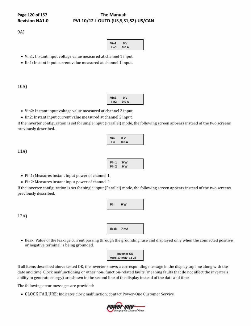
Page 120 of 157 The Manual: Revision NA1.0 PVI-10/12-I-OUTD-(US,S,S1,S2)-US/CAN
9A)
• Vin1: Instant input voltage value measured at channel 1 input. • Iin1: Instant input current value measured at channel 1 input.
10A)
• Vin2: Instant input voltage value measured at channel 2 input. • Iin2: Instant input current value measured at channel 2 input.
If the inverter configuration is set for single input (Parallel) mode, the following screen appears instead of the two screens previously described.
11A)
• Pin1: Measures instant input power of channel 1. • Pin2: Measures instant input power of channel 2.
If the inverter configuration is set for single input (Parallel) mode, the following screen appears instead of the two screens previously described.
12A)
• Ileak: Value of the leakage current passing through the grounding fuse and displayed only when the connected positive
or negative terminal is being grounded.
If all items described above tested OK, the inverter shows a corresponding message in the display top line along with the date and time. Clock malfunctioning or other non- function-related faults (meaning faults that do not affect the inverter's ability to generate energy) are shown in the second line of the display instead of the date and time.
The following error messages are provided:
• CLOCK FAILURE: Indicates clock malfunction; contact Power-One Customer Service
Inverter OK Wed 17 May 11 23
Ileak 7 mA
Pin 0 W
Pin 1 0 W Pin 2 0 W
Vin 0 V I in 0.0 A
Vin2 0 V I in2 0.0 A
Vin1 0 V I in1 0.0 A
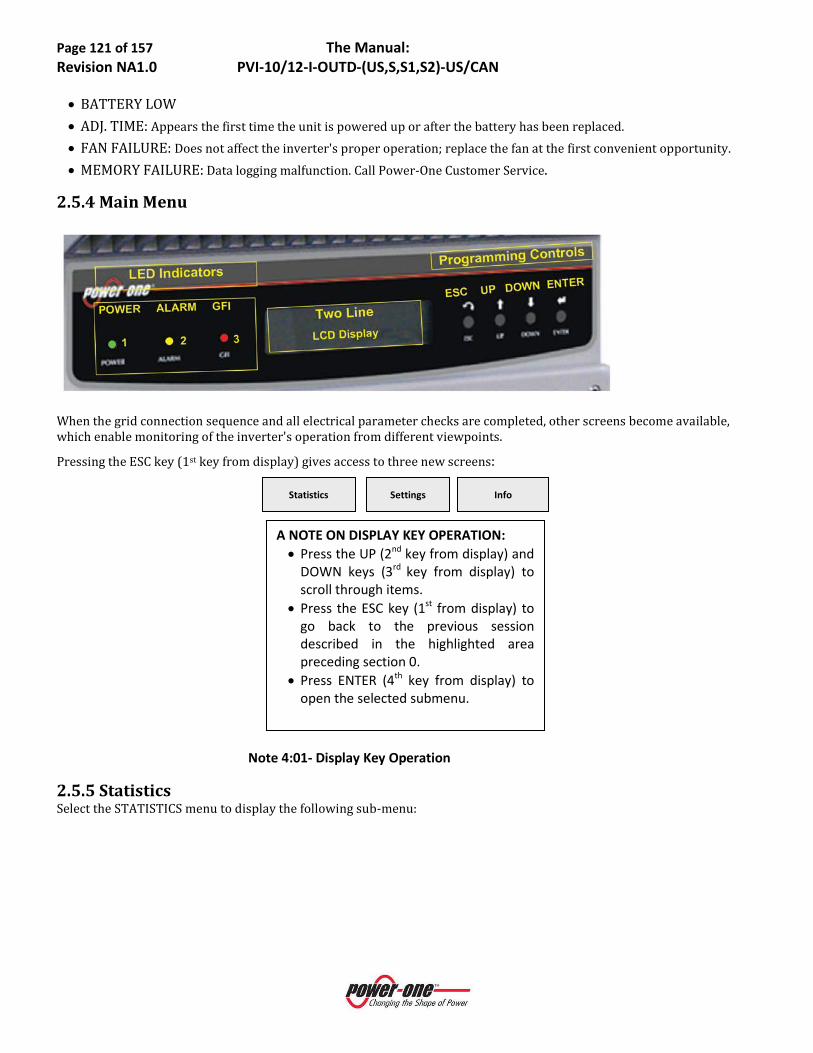
Page 121 of 157 The Manual: Revision NA1.0 PVI-10/12-I-OUTD-(US,S,S1,S2)-US/CAN
• BATTERY LOW • ADJ. TIME: Appears the first time the unit is powered up or after the battery has been replaced. • FAN FAILURE: Does not affect the inverter's proper operation; replace the fan at the first convenient opportunity. • MEMORY FAILURE: Data logging malfunction. Call Power-One Customer Service.
2.5.4 Main Menu
When the grid connection sequence and all electrical parameter checks are completed, other screens become available, which enable monitoring of the inverter's operation from different viewpoints.
Pressing the ESC key (1st key from display) gives access to three new screens:
Note 4:01- Display Key Operation
2.5.5 Statistics Select the STATISTICS menu to display the following sub-menu:
Info Settings Statistics
A NOTE ON DISPLAY KEY OPERATION: • Press the UP (2nd key from display) and
DOWN keys (3rd key from display) to scroll through items.
• Press the ESC key (1st from display) to go back to the previous session described in the highlighted area preceding section 0.
• Press ENTER (4th key from display) to open the selected submenu.

Page 122 of 157 The Manual: Revision NA1.0 PVI-10/12-I-OUTD-(US,S,S1,S2)-US/CAN
Lifetime Partial Today Last 7 days Last Month Last 30 Days Last 365 Days User period
The display shows only 2 lines; use the keys at the side of the display to scroll through items or open the corresponding sub-menus as described in Note 4:01 above. An arrow on the left side of the display highlights the current selection as shown in the following screen shot:
2.5.6 Lifetime Select Lifetime to view the following information:
• Time: Lifetime operation time • E-tot: Total energy produced • Val. : Economic gain • CO2: CO2 saving compared to fossil fuels
2.5.7 Partial Select Partial to view the following information:
• Time: Total operation time since the counter was last reset. * • E-par: Total energy produced since the counter was last reset. * • PPeak: Maximum peak power measured since the 'partial' counter was activated • Val. : Economic gain since the counter was last reset.* • CO2: CO2 saving compared to fossil fuels since counter was last reset. * * Hold the ENTER key (4th key from display) depressed for over 3 seconds to reset all counters in this submenu. After this time, a warning
sound is repeated 3 times.
TODAY Select Today to view the following information:
• E-tod: Total energy produced during the day. • Ppeak: Peak power value achieved during the day.
E-tod KWh Ppeak W Val. EUR CO2 kg
Time h E-par KWh Ppeak W Val. EUR CO2 kg
Time h E-tot KWh Val. EUR CO2 kg

Page 123 of 157 The Manual: Revision NA1.0 PVI-10/12-I-OUTD-(US,S,S1,S2)-US/CAN
• Val. : Economic gain during the day. • CO2: CO2 saving for the day compared to fossil fuels.
2.5.8 Last 7 days Select Last 7 Days to view the following information:
• E-7d: Total energy output over the last 7 days. • Val. : Economic gain over the last 7 days. • CO2: CO2 saving over the last 7 days compared to fossil fuels.
2.5.9 Last Month Select Last Month to view the following information:
• E-mon: Total energy output this month. • Val. : Economic gain this month. • CO2: CO2 saving this month compared to fossil fuels.
LAST 30 DAYS Select Last 30 Days to view the following information:
• E-30d: Total energy output over the last 30 days. • Val. : Economic gain over the last 30 days. • CO2: CO2 saving over the last 30 days compared to fossil fuels.
2.5.10 Last 365 Days Select Last 365 Days to view the following information:
• E-365: Total energy output over the last 365 days. • Val. : Economic gain over the last 365 days. • CO2: CO2 saving over the last 365 days compared to fossil fuels.
2.5.11 User Period Select User Period to view the energy saving during a period specified by the user:
• Press ENTER from the 'User period' screen to access the following sub-menu:
User period
E-365 KWh Val. EUR CO2 kg
E-30d KWh Val. EUR CO2 kg
E-mon KWh Val. EUR CO2 kg
E-7d KWh Val. EUR CO2 kg

Page 124 of 157 The Manual: Revision NA1.0 PVI-10/12-I-OUTD-(US,S,S1,S2)-US/CAN
• Use the display keys to set the start and end date of the period as follows:
Use ENTER to move from one field to the next (from left to right). Use ESC to go back to the previous field (from right to left). Press ESC repeatedly to go back to the previous menus as described in section 2.5.3.
To set the day:
o Press DOWN to scroll numbers backwards (from 31 to 1). o Press UP to scroll numbers forwards (from 1 to 31).
To set the month:
o Press DOWN to scroll months from December to January. o Press UP to scroll months from January to December.
If the dates set are inconsistent, the screen below alerts the user to the problem:
2.5.12 Settings Select SETTING from the Main Menu and [ENTER] to display the Password screen, which enables the user to access the Settings Menu:
• To enter this menu, the correct four digit password must be entered. o At initial set up, enter the default password [0000] unless the default password has been modified by the user (per
Note 4:01) in which case, enter the correct user password. o Follow instructions below to enter password digits into their proper location: Use ENTER to move from one digit location to the next (from left to right). Use ESC to go back to the previous figure (from right to left). Press DOWN to scroll numbers backwards (from 9 to 0). Press UP to scroll numbers forwards (from 0 to 9). Press ESC repeatedly to go back to the previous menus as described in section 2.5.3
• After entering the required password, press ENTER to access to the Settings Menu:
AddressDisplay SetServiceNew PasswordCashTimeLanguageVstartAlarmRemote ControlUV Prot.timeMPPTAlarm Message
The front panel display has only two lines; therefore, the display keys must be used to scroll through the menu items and/or open the corresponding sub-menus (see Note 4:01). An arrow on left side of the display highlights the current selection. Once the chosen item is selected, press [ENTER] to access the desired sub-menu. The following section provides descriptions of each of the available sub-menus.
Password ****
Data err
Start 23 June End 28 August

Page 125 of 157 The Manual: Revision NA1.0 PVI-10/12-I-OUTD-(US,S,S1,S2)-US/CAN
2.5.13 Address Selecting this function enables the bus addresses (for the inverter connected to the RS485 communication bus) to be set to an appropriate value. Address values are assigned manually using any value in the range [2 to 64]. Press the UP and DOWN keys to scroll numbers.
AUTO 2 3 ….. ….. 63 64 AUTO
If desired, the RS485 address can be selected automatically by the system. This function is active when AUTO is selected from the address list.
NOTE: If wiring multiple units using a daisy chain configuration, do not select AUTO configuration.
2.5.14 Display Set Selecting this function displays the following sub-menu enabling the user to set display features parameters:
Light Contrast Buzzer
The following sections describe the available settings:
• Light - select this menu choice and [ENTER] to open the Display light sub-menu:
Mode Intensity
o Select MODE and [ENTER] to allow setting the display backlighting.
ONOFFAuto
o ON: Light always ON. o OFF: Light always OFF. o AUTO: Automatic light setting - light turns on every time a key is pressed and stays on for 30 seconds before
fading OFF. o Select INTENSITY and [ENTER] to allow adjustment of the backlighting intensity from 1 to 9.
• Contrast: Select this menu choice and [ENTER] to adjust display lighting contrast o Available display light tones go from 0 to 9. o Press UP and DOWN keys to scroll the numbers and then press ENTER to confirm the selection.
• Buzzer: Select this menu choice and [ENTER] to set key tone setting, choices are: o ON: The key tone is ON. o OFF: The key tone is OFF.
2.5.15 Service This is a controlled access area of the operating system used by the factory to set certain control functions. Access is via an Advanced Password, which is a dedicated security code based on the unit serial number and access controlled by Power-
New Address Auto
New Address 62

Page 126 of 157 The Manual: Revision NA1.0 PVI-10/12-I-OUTD-(US,S,S1,S2)-US/CAN
One. Installers may need to access this menu for certain adjustments during the installation process, and Power-One will provide Advanced Password access to authorized installers to allow specific actions upon completion of required documentation.
2.5.16 New Password Selecting this function allows changing the default password (0000) to a personal code.
To set a personal code, use the display keys as follows: Use ENTER to move from one digit to the next (from left to right). Use ESC to go back to the previous digit (from right to left). Press ESC repeatedly to go back to the previous menus as described in section 2.5.3. Press DOWN to scroll numbers backwards (from 9 to 0). Press UP to scroll numbers forwards (from 0 to 9).
2.5.17 Cash Selecting this function enables the user to set the measurement units for earnings based on energy output.
• Name: Set desired currency, using the keys in the usual manner. The default currency is the Euro. • Val/KWh: This indicates the cost of 1 kWh expressed in the currency set. The default setting is Euro 0.50.
2.5.18 Time Selecting this function allows adjustment of the system time and date settings.
2.5.19 Language Selecting this function allows setting of the language desired for system prompts. Choices are Italian or English (default).
EnglishItaliano
2.5.20 Start-Up Voltage Selecting this function enables modification of the start-up voltage associated with each of the input channels to match requirements of the connected PV array. The voltage can be set over the range [120V to 350V]. The default setting for AURORA Inverter is 200V. Use the display keys to change the value of this parameter.
2.5.21 Alarm Selecting this function accesses the inverter’s alarm function, which is used for external controls or, for example, to activate a visual and/or audible alarm. The function has two different modes of operation. Select the desired mode using the up/down arrow keys and press [ENTER] to open the relevant sub-menu:
ProductionFault
The function controls a set of dry relay contacts, which can be wired by the user as either normally open (N.O.) or normally closed (N.C.); contacts are rated at 250V/1A. The terminals for this function are accessed via the front panel as shown in Figure 4:05.
VStart1 200V
Time 14:21 Date 17 May 2006
Name EUR Val/KWh 00.50
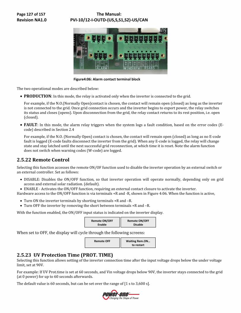
Page 127 of 157 The Manual: Revision NA1.0 PVI-10/12-I-OUTD-(US,S,S1,S2)-US/CAN
Figure4:06: Alarm contact terminal block
The two operational modes are described below:
• PRODUCTION: In this mode, the relay is activated only when the inverter is connected to the grid. For example, if the N.O.(Normally Open)contact is chosen, the contact will remain open (closed) as long as the inverter is not connected to the grid. Once grid connection occurs and the inverter begins to export power, the relay switches its status and closes (opens). Upon disconnection from the grid, the relay contact returns to its rest position, i.e. open (closed).
• FAULT: In this mode, the alarm relay triggers when the system logs a fault condition, based on the error codes (E-code) described in Section 2.4 For example, if the N.O. (Normally Open) contact is chosen, the contact will remain open (closed) as long as no E-code fault is logged (E-code faults disconnect the inverter from the grid). When any E-code is logged, the relay will change state and stay latched until the next successful grid reconnection, at which time it is reset. Note the alarm function does not switch when warning codes (W-code) are logged.
2.5.22 Remote Control Selecting this function accesses the remote ON/OF function used to disable the inverter operation by an external switch or an external controller. Set as follows:
• DISABLE: Disables the ON/OFF function, so that inverter operation will operate normally, depending only on grid access and external solar radiation. (default).
• ENABLE - Activates the ON/OFF function, requiring an external contact closure to activate the inverter. Hardware access to the ON/OFF function is via terminals +R and -R, shown in Figure 4:06. When the function is active,
• Turn ON the inverter terminals by shorting terminals +R and –R. • Turn OFF the inverter by removing the short between terminals +R and –R.
With the function enabled, the ON/OFF input status is indicated on the inverter display.
When set to OFF, the display will cycle through the following screens:
2.5.23 UV Protection Time (PROT. TIME) Selecting this function allows setting of the inverter connection time after the input voltage drops below the under voltage limit, set at 90V.
For example: If UV Prot.time is set at 60 seconds, and Vin voltage drops below 90V, the inverter stays connected to the grid (at 0 power) for up to 60 seconds afterwards.
The default value is 60 seconds, but can be set over the range of [1 s to 3,600 s].
Waiting Rem.ON… to restart
Remote OFF
Remote ON/OFF Disable
Remote ON/OFF Enable
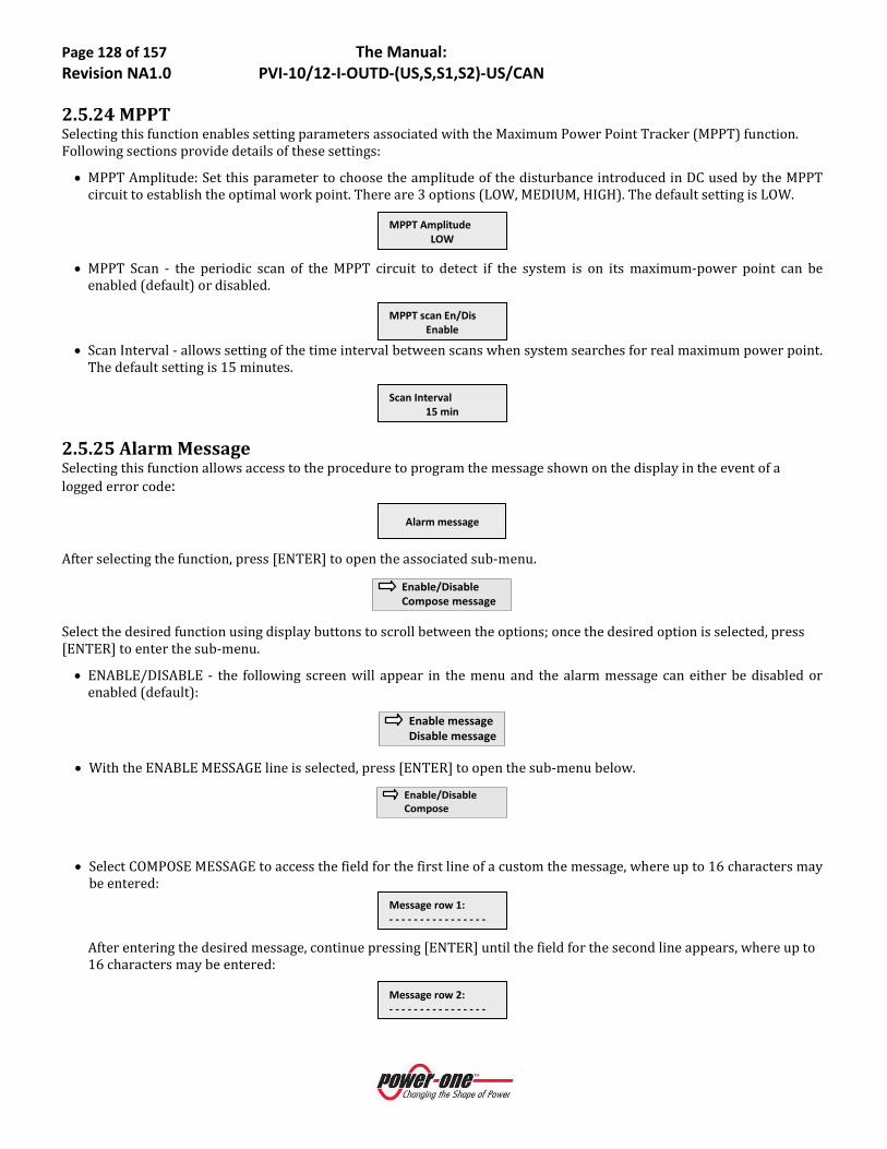
Page 128 of 157 The Manual: Revision NA1.0 PVI-10/12-I-OUTD-(US,S,S1,S2)-US/CAN
2.5.24 MPPT Selecting this function enables setting parameters associated with the Maximum Power Point Tracker (MPPT) function. Following sections provide details of these settings:
• MPPT Amplitude: Set this parameter to choose the amplitude of the disturbance introduced in DC used by the MPPT circuit to establish the optimal work point. There are 3 options (LOW, MEDIUM, HIGH). The default setting is LOW.
• MPPT Scan - the periodic scan of the MPPT circuit to detect if the system is on its maximum-power point can be
enabled (default) or disabled.
• Scan Interval - allows setting of the time interval between scans when system searches for real maximum power point.
The default setting is 15 minutes.
2.5.25 Alarm Message Selecting this function allows access to the procedure to program the message shown on the display in the event of a logged error code:
After selecting the function, press [ENTER] to open the associated sub-menu.
Enable/DisableCompose message
Select the desired function using display buttons to scroll between the options; once the desired option is selected, press [ENTER] to enter the sub-menu.
• ENABLE/DISABLE - the following screen will appear in the menu and the alarm message can either be disabled or enabled (default):
Enable messageDisable message
• With the ENABLE MESSAGE line is selected, press [ENTER] to open the sub-menu below.
Enable/DisableCompose
• Select COMPOSE MESSAGE to access the field for the first line of a custom the message, where up to 16 characters may be entered:
After entering the desired message, continue pressing [ENTER] until the field for the second line appears, where up to 16 characters may be entered:
Message row 2: - - - - - - - - - - - - - - - -
Message row 1: - - - - - - - - - - - - - - - -
Alarm message
Scan Interval 15 min
MPPT scan En/Dis Enable
MPPT Amplitude LOW

Page 129 of 157 The Manual: Revision NA1.0 PVI-10/12-I-OUTD-(US,S,S1,S2)-US/CAN
• To write the message always use the display keys in the following way: o Use ENTER (4th key) to move from one figure to the next (from left to right). o Use ESC (1st key) to go back to the previous position (from right to left). o Press ESC repeatedly to go back to the previous menus as described in section 2.5.3. o Use UP (2nd key) to scroll upwards through the numbers, letters and symbols. o Use DOWN (3rd key) to scroll downwards through the numbers, letters and symbols.
2.5.26 Information Selecting this menu allows display all Aurora Inverter data, the chosen language, and enables reading and/or modification of the grid standard by means of the special selector switches.
o Part No. (part number) o Serial No. – Wk – Yr (serial number, week, year) o Fw rel (firmware revision level) o Country Selector
The Country Selector menu allows display of the user-set grid standard currently programmed into the inverter (Current Value), and the future grid standard to be used when the inverter is next switched-on, if a new value has been selected. Once a grid standard has been operating for 24 hours, the inverter control locks the selector switches shown in Part 3, Section 2.5.1 of respective unit number. Changing the grid standard after the 24 hour timer has elapsed requires user to contact Power-One Technical Service. The time available for making changes to the grid standard can be checked (Residual Time).
3.0 DATA CHECK AND COMMUNICATION The Aurora inverters have remote monitoring and capabilities which are accessed externally using an RS485 communication port. The AURORA Inverter is provisioned with the communication capability as a standard feature, and all that is needed for remote monitoring is monitoring hardware which connects to the RS485 port and collects the available data. Following sections detail the wiring connections necessary to implement the RS485 bus. See Part 3 for specific wiring directions.

Page 130 of 157 The Manual: Revision NA1.0 PVI-10/12-I-OUTD-(US,S,S1,S2)-US/CAN
PART 5: TROUBLESHOOTING

Page 131 of 157 The Manual: Revision NA1.0 PVI-10/12-I-OUTD-(US,S,S1,S2)-US/CAN
5: 1.0 TROUBLESHOOTING AURORA TRIO Inverters comply with the standards set for grid-tied operation, safety, and electromagnetic compatibility.
Before the product is dispatched various tests are carried out successfully to ensure: functioning, protection devices, performance and durability.
Such tests, together with the Power-One quality assurance system, support optimal operation of the AURORA Inverter.
In case of any possible malfunction of the inverter, solve problems as follows:
● Work under safe conditions. Check that the connections between AURORA, photovoltaic field and power distribution network have been made correctly as stated in Part 1 Introduction & Safety and Part 3 Wall Mount & Wire Configuration.
● Carefully observe which LED is flashing and read the signal appearing on the display; then, following the instructions given in the Sections below, try to identify the type of fault found.
1.2 LED INDICATORS
Figure 5:01- Location of the buttons and LEDs
There are three LEDs on the left side of the display:
4. The green 'Power' LED indicates that AURORA Inverter is operating correctly.
This LED flashes upon start-up, during the grid check routine. If a correct grid voltage is detected and solar radiation is strong enough to start-up the unit, the LED stays on steady. If not, the LED keeps flashing until solar radiation becomes strong enough to start-up the inverter. In this condition, the display will read 'Waiting Sun….'
5. The yellow 'FAULT' LED indicates that the AURORA Inverter has detected a fault condition. A fault description will appear on the display.
6. The red 'GFI' (ground fault) LED indicates that AURORA Inverter is detecting a ground fault in the DC side of the photovoltaic system. When this kind of fault is detected, the AURORA Inverter disconnects from the grid and the corresponding fault indication appears on the LCD display. AURORA Inverter remains in this condition until the operator presses the ESC key to re-start the grid connection sequence. If pressing the ESC key doesn’t clear the ground fault check the ground-fault, fuse located in the switchbox. If AURORA Inverter does not reconnect to the grid, see Section 1.6: The Power-One Service Call.
7. The following table shows all the possible LED-signalling indications related to the operational status of AURORA Inverter.

Page 132 of 157 The Manual: Revision NA1.0 PVI-10/12-I-OUTD-(US,S,S1,S2)-US/CAN
Key:
LED on
LED flashing
LED off
Any of the above conditions
LED STATUS OPERATIONAL STATUS NOTES
1
1: green:
2: yellow:
3: red:
AURORA self-disconnects during night-time
Input voltage less than 90 Vdc at both inputs
2
1: green:
2: yellow:
3: red:
AURORA Inverter initialization, settings loading, and waiting for grid check
It is in transition status while operating conditions are being checked.
3
1: green:
2: yellow:
3: red:
AURORA Inverter is powering the grid
Standard machine operation (search for maximum power point or constant voltage)
4
1: green:
2: yellow:
3: red:
System insulation device faulty Leakage to ground found
5
1: green:
2: yellow:
3: red:
Defect – fault!!! The fault can be inside or outside the inverter. See the alarm appearing on the LCD display.
6
1: green:
2: yellow:
3: red:
Installation Phase: AURORA Inverter is disconnected from the grid.
During installation, it indicates set-up phase of the address for RS-485 communication.
7
1: green:
2: yellow:
3: red:
Grid disconnection Indicates a missing grid condition
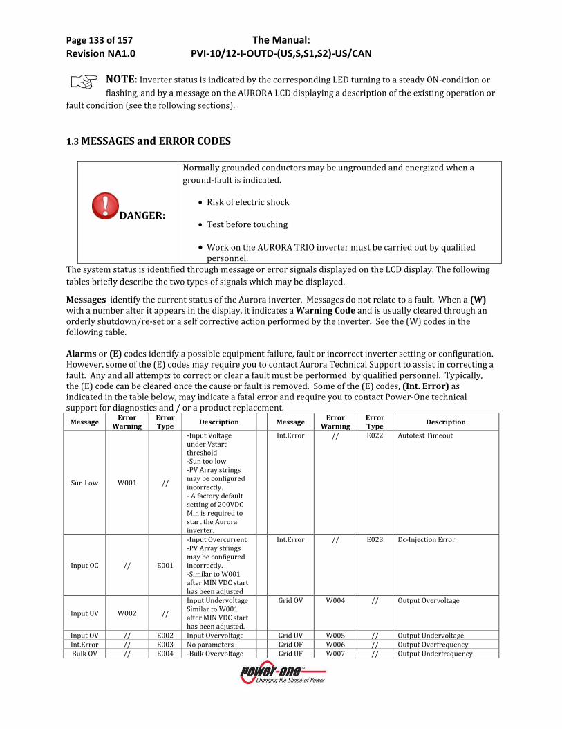
Page 133 of 157 The Manual: Revision NA1.0 PVI-10/12-I-OUTD-(US,S,S1,S2)-US/CAN
NOTE: Inverter status is indicated by the corresponding LED turning to a steady ON-condition or flashing, and by a message on the AURORA LCD displaying a description of the existing operation or
fault condition (see the following sections).
1.3 MESSAGES and ERROR CODES
DANGER:
Normally grounded conductors may be ungrounded and energized when a ground-fault is indicated.
• Risk of electric shock
• Test before touching
• Work on the AURORA TRIO inverter must be carried out by qualified personnel.
The system status is identified through message or error signals displayed on the LCD display. The following tables briefly describe the two types of signals which may be displayed.
Messages identify the current status of the Aurora inverter. Messages do not relate to a fault. When a (W) with a number after it appears in the display, it indicates a Warning Code and is usually cleared through an orderly shutdown/re-set or a self corrective action performed by the inverter. See the (W) codes in the following table. Alarms or (E) codes identify a possible equipment failure, fault or incorrect inverter setting or configuration. However, some of the (E) codes may require you to contact Aurora Technical Support to assist in correcting a fault. Any and all attempts to correct or clear a fault must be performed by qualified personnel. Typically, the (E) code can be cleared once the cause or fault is removed. Some of the (E) codes, (Int. Error) as indicated in the table below, may indicate a fatal error and require you to contact Power-One technical support for diagnostics and / or a product replacement.
Message Error Warning
Error Type Description Message Error
Warning Error Type Description
Sun Low W001 //
-Input Voltage under Vstart threshold -Sun too low -PV Array strings may be configured incorrectly. - A factory default setting of 200VDC Min is required to start the Aurora inverter.
Int.Error // E022 Autotest Timeout
Input OC // E001
-Input Overcurrent -PV Array strings may be configured incorrectly. -Similar to W001 after MIN VDC start has been adjusted
Int.Error // E023 Dc-Injection Error
Input UV W002 //
Input Undervoltage Similar to W001 after MIN VDC start has been adjusted.
Grid OV W004 // Output Overvoltage
Input OV // E002 Input Overvoltage Grid UV W005 // Output Undervoltage Int.Error // E003 No parameters Grid OF W006 // Output Overfrequency Bulk OV // E004 -Bulk Overvoltage Grid UF W007 // Output Underfrequency
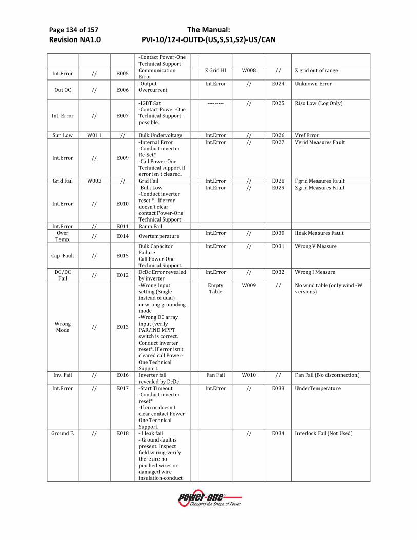
Page 134 of 157 The Manual: Revision NA1.0 PVI-10/12-I-OUTD-(US,S,S1,S2)-US/CAN
-Contact Power-One Technical Support
Int.Error // E005 Communication Error
Z Grid HI W008 // Z grid out of range
Out OC // E006 -Output Overcurrent
Int.Error // E024 Unknown Error –
Int. Error // E007
-IGBT Sat -Contact Power-One Technical Support- possible.
--------- // E025 Riso Low (Log Only)
Sun Low W011 // Bulk Undervoltage Int.Error // E026 Vref Error
Int.Error // E009
-Internal Error -Conduct inverter Re-Set* -Call Power-One Technical support if error isn’t cleared.
Int.Error // E027 Vgrid Measures Fault
Grid Fail W003 // Grid Fail Int.Error // E028 Fgrid Measures Fault
Int.Error // E010
-Bulk Low -Conduct inverter reset * - if error doesn’t clear, contact Power-One Technical Support
Int.Error // E029 Zgrid Measures Fault
Int.Error // E011 Ramp Fail Over
Temp. // E014 Overtemperature Int.Error // E030 Ileak Measures Fault
Cap. Fault // E015
Bulk Capacitor Failure Call Power-One Technical Support.
Int.Error // E031 Wrong V Measure
DC/DC Fail // E012 DcDc Error revealed
by inverter Int.Error // E032 Wrong I Measure
Wrong Mode // E013
-Wrong Input setting (Single instead of dual) or wrong grounding mode -Wrong DC array input (verify PAR/IND MPPT switch is correct. Conduct inverter reset*. If error isn’t cleared call Power-One Technical Support.
Empty Table
W009 // No wind table (only wind -W versions)
Inv. Fail // E016 Inverter fail revealed by DcDc
Fan Fail W010 // Fan Fail (No disconnection)
Int.Error // E017 -Start Timeout -Conduct inverter reset* -If error doesn’t clear contact Power-One Technical Support.
Int.Error // E033 UnderTemperature
Ground F. // E018 - I leak fail - Ground-fault is present. Inspect field wiring-verify there are no pinched wires or damaged wire insulation-conduct
// E034 Interlock Fail (Not Used)

Page 135 of 157 The Manual: Revision NA1.0 PVI-10/12-I-OUTD-(US,S,S1,S2)-US/CAN
inverter reset*-contact Power-One Technical Support.
Int.Error // E019 Ileak Sensor fail // E035 Remote Off Int.Error // E020 DcDc relay fail // E036 Vout Avg Error Int.Error // E021 Inverter relay fail W012 // Clock Battery Low (No
disconnection) W013 // Clock Failure (No
disconnection) *To conduct the inverter reset, turn the AC and the DC OFF. Turn DC ON and wait for sun. Turn AC ON. Table 5:01 Messages and Error Codes
1.4 LCD DISPLAY
1.4.1 Connection of the System to the Grid A two-line LCD display is located on the front panel shows the following:
Inverter operating status and statistics; Service messages for the operator; Alarm and fault messages. During regular operation, the display will cycle through available data. The display changes to a different screen every 5 seconds, or screens may be scrolled manually by pressing the UP (2nd key from display) and DOWN keys (3rd key from display).
1) These two screens are displayed at inverter start-up:
6) The following screens may appear while waiting for the connection to be established:
- While the system checks for grid connection to be established ('Missing Grid'), the yellow LED next to the display turns on steady, while the green LED flashes.
- When waiting for solar radiation ('Waiting Sun'), the green LED turns on steady.
- As soon as the 'Missing Grid' and 'Waiting Sun' conditions are met successfully, the inverter is connected.
7) This display shows the time (seconds) remaining to complete the output voltage and frequency values check.
Waiting Sun Missing Grid
POWER-ONE Initializing… Please wait

Page 136 of 157 The Manual: Revision NA1.0 PVI-10/12-I-OUTD-(US,S,S1,S2)-US/CAN
4) This display shows the instant output voltage value and whether it is within/outside range.
5) This displays the instant output frequency value and whether it is within/outside range.
6) If the measured instant values of voltage (point 4) and frequency (point 5) are outside the allowed range, the following screens are scrolled alternately:
Next connections (screen 3) → Vgrid (screen 4) →-Fgrid (screen 5)
1.5 FIRST PHASE- ELECTRIC PARAMETER CHECK Clock malfunctioning or other non- function-related faults (meaning faults that do not affect the inverter's ability to generate energy) are shown in the second line of the display instead of the date and time.
The following error messages are provided:
• CLOCK FAILURE: Indicates clock malfunction; contact Power-One Customer Service • BATTERY LOW • ADJ. TIME: Appears the first time the unit is powered up or after the battery has been replaced. • FAN FAILURE: Does not affect the inverter's proper operation; replace the fan at the first convenient
opportunity. • MEMORY FAILURE: Data logging malfunction. Call Power-One Customer Service.
If the malfunction cannot be cleared by following these instructions, contact the service center or the installer (see Section 1.6 below). Before contacting Power-One Customer Service, please make the following information available in order to maximize the effectiveness of the intervention:
Fgrid 60.17 Hz In range
Vgrid 223.8 V In range
Next connections: 2 secs

Page 137 of 157 The Manual: Revision NA1.0 PVI-10/12-I-OUTD-(US,S,S1,S2)-US/CAN
1.6 THE POWER-ONE SERVICE CALL INFORMATION ON AURORA TRIO INVERTER
NOTE: above information available directly from the LCD display
Additional helpful information when troubleshooting with the Power-One Technical Service Engineers:
Provide a brief description of the fault. Information on the Photovoltaic Field Brand and model of photovoltaic panels Identify the System structure:
• Maximum array voltage and current values • Number of strings in the array • Number of panels for each string • Can the fault be reproduced? If so, how? • Is the fault cyclical in nature? If so, how often? • Was the fault apparent at the time of installation? • If so, has it got worse? • Describe the atmospheric conditions at the time the fault appears/appeared.
Power-One Customer Service & Technical Support Aurora® Power Service (Americas) Phone: 877-261-1374
AURORA model? Serial number? Week of production? Which LED is flashing? Steady or flashing light? What signals are shown on the
display?

Page 138 of 157 The Manual: Revision NA1.0 PVI-10/12-I-OUTD-(US,S,S1,S2)-US/CAN
PART 6: MAINTENANCE GUIDE
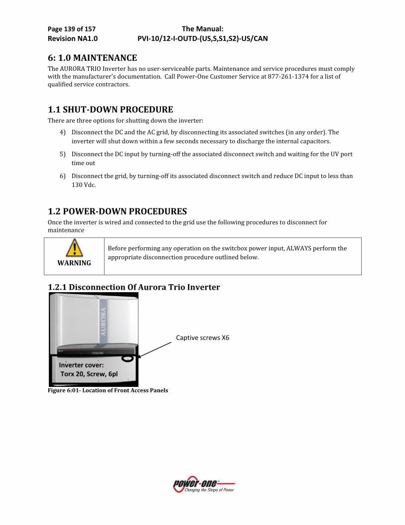
Page 139 of 157 The Manual: Revision NA1.0 PVI-10/12-I-OUTD-(US,S,S1,S2)-US/CAN
6: 1.0 MAINTENANCE The AURORA TRIO Inverter has no user-serviceable parts. Maintenance and service procedures must comply with the manufacturer's documentation. Call Power-One Customer Service at 877-261-1374 for a list of qualified service contractors.
1.1 SHUT-DOWN PROCEDURE There are three options for shutting down the inverter:
4) Disconnect the DC and the AC grid, by disconnecting its associated switches (in any order). The inverter will shut down within a few seconds necessary to discharge the internal capacitors.
5) Disconnect the DC input by turning-off the associated disconnect switch and waiting for the UV port time out
6) Disconnect the grid, by turning-off its associated disconnect switch and reduce DC input to less than 130 Vdc.
1.2 POWER-DOWN PROCEDURES Once the inverter is wired and connected to the grid use the following procedures to disconnect for maintenance
WARNING
Before performing any operation on the switcbox power input, ALWAYS perform the appropriate disconnection procedure outlined below.
1.2.1 Disconnection Of Aurora Trio Inverter
Figure 6:01- Location of Front Access Panels
Inverter cover: Torx 20, Screw, 6pl
Captive screws X6

Page 140 of 157 The Manual: Revision NA1.0 PVI-10/12-I-OUTD-(US,S,S1,S2)-US/CAN
Location
Indicator
Details Location Indicator
Details
A Grid Selector/Country Code – thumbwheel switches
04 H MPPT Input Selector Switch
Choose PAR or IND MPPT Operation
B DC Array: MPPT 1 input Note 1 below J Alarm Out Terminals for External Alarm
Note 3 below
C DC Array: MPPT2 input Note 1 below K RS485 Bus Connection Via RJ485 Connector
Use with CAT5 Cable
D Main PE Ground Terminal
Note 1 below L RS485 Bus Connection Via Screw Terminals
Note 3 below
E 3 ø AC Grid Output Terminals Note 2
below
M RS485 Termination Switch
See Signal Connection Section for more detail
F 3 ø AC Grid Neutral Terminal for 4W Grid Connection
Note 2
below
N Remote ON/OFF Switch
See Signal Connection Section for more detail
G 3PHMOD Switch
3ø Mode Selector
Choose 3W or 4W Grid
O GFD Fuse

Page 141 of 157 The Manual: Revision NA1.0 PVI-10/12-I-OUTD-(US,S,S1,S2)-US/CAN
Connection
Notes: 1. Terminals accept wire range up to #4AWG (Refer to local code for appropriate wire size); torque to 13in-lb.
2. Terminals accept wire range up to #4AWG (Refer to local code for appropriate wire size); torque to 13in-lb.
3. Mating terminal in hardware kit. Terminals accept wire size range up to #4AWG; torque to 13 in-lb.
Figure 6:02 PVI-10/12-I-OUTD-US/CAN Wiring Connection Details
1.3 GROUND FAULT DETECTOR FUSE REPLACEMENT
DANGER: Normally grounded conductors may be ungrounded and energized when a ground-fault is indicated.
• Risk of electric shock
• Test before touching
• Work on the AURORA TRIO inverter must be carried out by qualified personnel.
Figure 6:03 GFD Fuse Location O
WARNING Before performing any operation on the switchbox power input or on the inverter, ALWAYS perform the disconnection procedure as explained in Section 1.0.

Page 142 of 157 The Manual: Revision NA1.0 PVI-10/12-I-OUTD-(US,S,S1,S2)-US/CAN
The AURORA TRIO, PVI-10.0 isolated inverter series has separate versions depending on the array grounding preference. This functionality is identified within the part number as noted in Part 1: Introduction & Safety.
NOTE: Ensure the proper part number is ordered as required to fulfil project requirements.
The GFD Fuse holder is located on the bottom of the inverter (inside the switchbox for AURORA TRIO-S/S2-US models) as shown in Figure 6:03 . Unscrew the fuse holder in order to change the fuse if necessary. Replace only with appropriate fuses:
Littelfuse KLKD-1 (10x38mm cartridge fuse, 600V)
1.4 CR2032 LITHIUM BATTERY REPLACEMENT
WARNING
• Before performing any operation on the switchbox power input or on the inverter, ALWAYS perform the disconnection procedure as explained in Part 4: Operations of this manual.
• The replacement of this battery should be performed only by trained personnel.
Inside the AURORA TRIO Inverter there is a CR2032 lithium battery. When this battery is at end-of-life, a message will be shown in the display informing that the battery needs to be replaced.
The battery is visible after removing the AURORA PV Inverter's front panel. Refer Figure 6.01 above for the procedure to remove the front panel.
To insert the new battery into its holder, slide the battery at a 30° angle pushing it into insertion as shown in Figure 6:04 below. When pushed on into insertion it should seat into the correct position within the holder.
After battery replacement is completed, re-install and secure the front panel of the inverter and perform the START-UP procedure in Part 4: Operations.
Figure 6:04 Lithium Battery Replacement

Page 143 of 157 The Manual: Revision NA1.0 PVI-10/12-I-OUTD-(US,S,S1,S2)-US/CAN
PART 7: THE APPENDIX
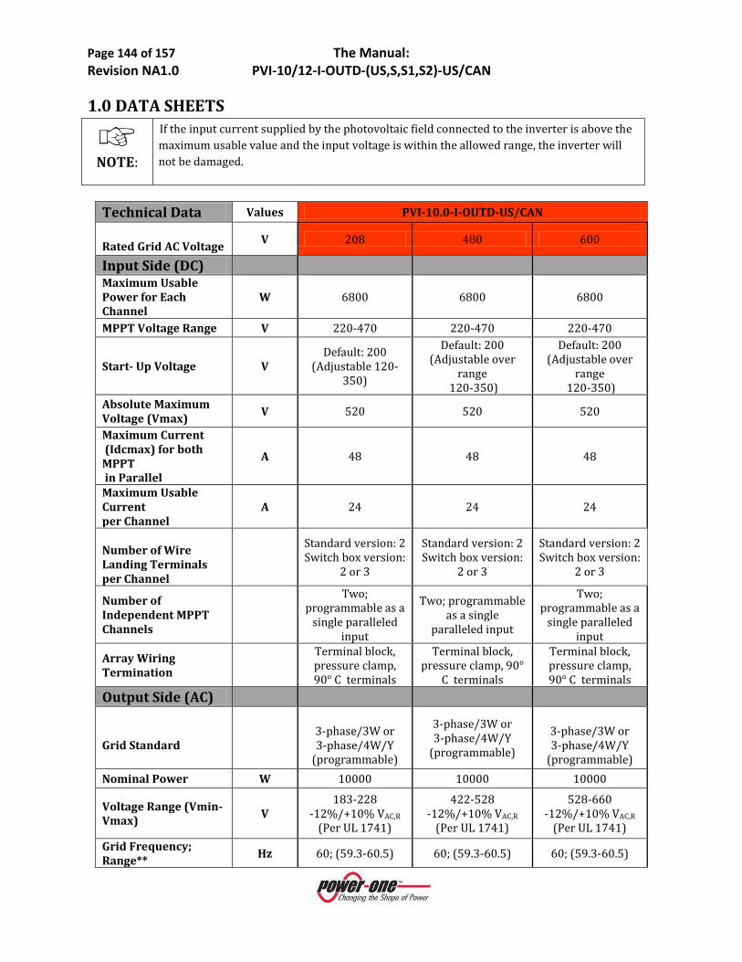
Page 144 of 157 The Manual: Revision NA1.0 PVI-10/12-I-OUTD-(US,S,S1,S2)-US/CAN
1.0 DATA SHEETS
NOTE:
If the input current supplied by the photovoltaic field connected to the inverter is above the maximum usable value and the input voltage is within the allowed range, the inverter will not be damaged.
Technical Data Values PVI-10.0-I-OUTD-US/CAN Rated Grid AC Voltage V 208 480 600
Input Side (DC) Maximum Usable Power for Each Channel
W 6800 6800 6800
MPPT Voltage Range V 220-470 220-470 220-470
Start- Up Voltage V Default: 200
(Adjustable 120-350)
Default: 200 (Adjustable over
range 120-350)
Default: 200 (Adjustable over
range 120-350)
Absolute Maximum Voltage (Vmax) V 520 520 520
Maximum Current (Idcmax) for both MPPT in Parallel
A 48 48 48
Maximum Usable Current per Channel
A 24 24 24
Number of Wire Landing Terminals per Channel
Standard version: 2 Switch box version:
2 or 3
Standard version: 2 Switch box version:
2 or 3
Standard version: 2 Switch box version:
2 or 3
Number of Independent MPPT Channels
Two; programmable as a
single paralleled input
Two; programmable as a single
paralleled input
Two; programmable as a
single paralleled input
Array Wiring Termination
Terminal block, pressure clamp, 90° C terminals
Terminal block, pressure clamp, 90°
C terminals
Terminal block, pressure clamp, 90° C terminals
Output Side (AC)
Grid Standard
3-phase/3W or 3-phase/4W/Y
(programmable)
3-phase/3W or 3-phase/4W/Y
(programmable)
3-phase/3W or 3-phase/4W/Y
(programmable) Nominal Power W 10000 10000 10000
Voltage Range (Vmin-Vmax) V
183-228 -12%/+10% VAC,R
(Per UL 1741)
422-528 -12%/+10% VAC,R
(Per UL 1741)
528-660 -12%/+10% VAC,R
(Per UL 1741) Grid Frequency; Range** Hz 60; (59.3-60.5) 60; (59.3-60.5) 60; (59.3-60.5)
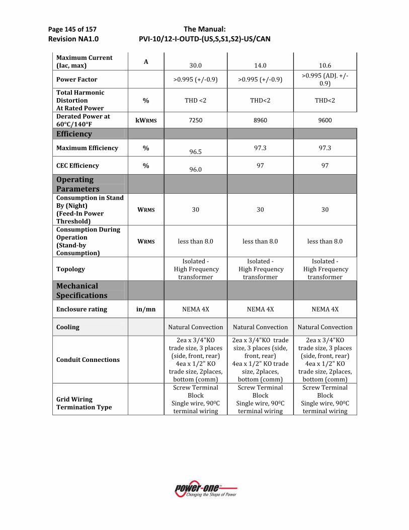
Page 145 of 157 The Manual: Revision NA1.0 PVI-10/12-I-OUTD-(US,S,S1,S2)-US/CAN
Maximum Current (Iac, max) A
30.0
14.0
10.6
Power Factor >0.995 (+/-0.9) >0.995 (+/-0.9) >0.995 (ADJ. +/-0.9)
Total Harmonic Distortion At Rated Power
% THD <2 THD<2 THD<2
Derated Power at 60°C/140°F kWRMS 7250 8960 9600
Efficiency Maximum Efficiency %
96.5 97.3 97.3
CEC Efficiency % 96.0 97 97
Operating Parameters Consumption in Stand By (Night) (Feed-In Power Threshold)
WRMS 30 30 30
Consumption During Operation (Stand-by Consumption)
WRMS less than 8.0 less than 8.0 less than 8.0
Topology
Isolated - High Frequency
transformer
Isolated - High Frequency
transformer
Isolated - High Frequency
transformer Mechanical Specifications
Enclosure rating in/mn NEMA 4X NEMA 4X NEMA 4X
Cooling Natural Convection Natural Convection Natural Convection
Conduit Connections
2ea x 3/4"KO trade size, 3 places (side, front, rear)
4ea x 1/2" KO trade size, 2places,
bottom (comm)
2ea x 3/4"KO trade size, 3 places (side,
front, rear) 4ea x 1/2" KO trade
size, 2places, bottom (comm)
2ea x 3/4"KO trade size, 3 places (side, front, rear)
4ea x 1/2" KO trade size, 2places,
bottom (comm)
Grid Wiring Termination Type
Screw Terminal Block
Single wire, 900C terminal wiring
Screw Terminal Block
Single wire, 900C terminal wiring
Screw Terminal Block
Single wire, 900C terminal wiring
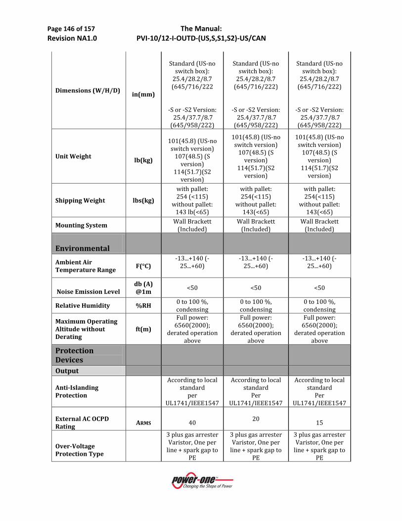
Page 146 of 157 The Manual: Revision NA1.0 PVI-10/12-I-OUTD-(US,S,S1,S2)-US/CAN
Dimensions (W/H/D) in(mm)
Standard (US-no
switch box): 25.4/28.2/8.7 (645/716/222
-S or -S2 Version: 25.4/37.7/8.7
(645/958/222)
Standard (US-no
switch box): 25.4/28.2/8.7
(645/716/222)
-S or -S2 Version: 25.4/37.7/8.7
(645/958/222)
Standard (US-no
switch box): 25.4/28.2/8.7
(645/716/222)
-S or -S2 Version: 25.4/37.7/8.7
(645/958/222)
Unit Weight lb(kg)
101(45.8) (US-no switch version)
107(48.5) (S version)
114(51.7)(S2 version)
101(45.8) (US-no switch version)
107(48.5) (S version)
114(51.7)(S2 version)
101(45.8) (US-no switch version)
107(48.5) (S version)
114(51.7)(S2 version)
Shipping Weight lbs(kg)
with pallet: 254 (<115)
without pallet: 143 lb(<65)
with pallet: 254(<115)
without pallet: 143(<65)
with pallet: 254(<115)
without pallet: 143(<65)
Mounting System Wall Brackett
(Included) Wall Brackett
(Included) Wall Brackett
(Included) Environmental
Ambient Air Temperature Range F(°C)
-13...+140 (-25...+60)
-13...+140 (-25...+60)
-13...+140 (-25...+60)
Noise Emission Level
db (A) @1m <50 <50 <50
Relative Humidity %RH 0 to 100 %, condensing
0 to 100 %, condensing
0 to 100 %, condensing
Maximum Operating Altitude without Derating
ft(m)
Full power: 6560(2000);
derated operation above
Full power: 6560(2000);
derated operation above
Full power: 6560(2000);
derated operation above
Protection Devices
Output
Anti-Islanding Protection
According to local standard
per UL1741/IEEE1547
According to local standard
Per UL1741/IEEE1547
According to local standard
Per UL1741/IEEE1547
External AC OCPD Rating
ARMS
40 20
15
Over-Voltage Protection Type
3 plus gas arrester Varistor, One per
line + spark gap to PE
3 plus gas arrester Varistor, One per
line + spark gap to PE
3 plus gas arrester Varistor, One per
line + spark gap to PE

Page 147 of 157 The Manual: Revision NA1.0 PVI-10/12-I-OUTD-(US,S,S1,S2)-US/CAN
Input Reverse Polarity Protection yes, diode yes, diode yes, diode
Maximum Short Circuit Current Limit per Channel
A 29 29 29
Over-Voltage Protection Type
Varistor, two for per MPPT
Varistor, two per each MPPT
Varistor, two per each MPPT
PV Array Ground Fault Detection
According to local standard
GFDI (GFD fuse) per UL1741/ NEC690.5 (A)
According to local standard
GFDI (GFD fuse) per UL1741/NEC690.5
(A)
According to local standard
GFDI (GFD fuse) per
UL1741/NEC690.5 (A)
DC Switch Current Rating (Per Contact)
A/V 32/600 32/600 32/600
Ground Fault Detector Fuse Size/ Type
A/V mm
1/600 10x38 1/600/10x38 1/600/10x38
Optional String Combiner Fuse Size/Type
A, A/V mm
12, 15/600 10x38 12, 15/600/10x38 12, 15/600/10x38
Isolation Level
POS or NEG ground referenced
array (version specific)
POS or NEG ground referenced
array (version specific)
POS or NEG ground referenced
array (version specific)
Safety and EMC Standard
UL1741, CSA22.2 #107.1-01
UL1741, CSA22.2 #107.1-01
UL1741, CSA22.2 #107.1-01
Safety Approval cCSAus cCSAus cCSAus Features- Communication
User-Interface (Display)
16 Characters X 2 lines
LCD display (Front Panel
Chassis Mount)
16 Characters X 2 lines
LCD display (Front Panel Chassis
Mount)
16 Characters X 2 lines
LCD display (Front Panel
Chassis Mount) Remote Monitoring (1xRS485 incl.) RS485 RS485 RS485
Wired Local Monitoring (1xRS485 incl.)
PVI-DESKTOP
(opt) Use included
RS485 port and (optional) PVI
RS485-USB adaptor with
AURORA Communicator
Software
PVI-DESKTOP (opt) Use included RS485 port and (optional)
PVI RS485-USB adaptor with
AURORA Communicator
Software
PVI-DESKTOP
(opt) Use included
RS485 port and (optional) PVI
RS485-USB adaptor with
AURORA Communicator
Software

Page 148 of 157 The Manual: Revision NA1.0 PVI-10/12-I-OUTD-(US,S,S1,S2)-US/CAN
Wireless Local Monitoring
PVI-DESKTOP (opt),
WITH PVI-RADIO MODULE (opt)
PVI-DESKTOP (opt) WITH PVI-RADIO
MODULE (opt)
PVI-DESKTOP (opt)
WITH PVI-RADIO MODULE (opt)
Standard Warranty Years 10 10 10 Extended Warranty Years 15 & 20 15 & 20 15 & 20
Available Models For available models and ordering information, see listing in section 2.0 of this manual.
*All data is subject to change without notice ** Adjustable low trip point to 57Hz. Contact manufacturer for details ***Inverter can apply that much current- Breaker will pop
Technical Data Values PVI-12.0-I-OUTD-US/CAN Rated Grid AC Voltage V 480 600
Input Side (DC) Maximum Usable Power for Each Channel
W 6800 6800
MPPT Voltage Range V 250-470 250-470
Start- Up Voltage V
Default: 200 (Adjustable over
range 120-350)
Default: 200 (Adjustable over range
120-350)
Absolute Maximum Voltage (Vmax) V 520 520
Maximum Current (Idcmax) for both MPPT in Parallel
A 50 50
Maximum Usable Current per Channel A 25 25
Number of Wire Landing Terminals per Channel
Standard version: 2
Switch box version: 2 or 3
Standard version: 2 Switch box version: 2 or
3
Number of Independent MPPT Channels
Two; programmable as a
single paralleled input
Two; programmable as a single paralleled input
Array Wiring Termination
Terminal block, pressure clamp, 90° C termimals
Terminal block, pressure clamp, 90° C termimals
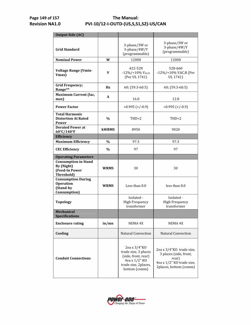
Page 149 of 157 The Manual: Revision NA1.0 PVI-10/12-I-OUTD-(US,S,S1,S2)-US/CAN
Output Side (AC)
Grid Standard
3-phase/3W or 3-phase/4W/Y
(programmable)
3-phase/3W or 3-phase/4W/Y
(programmable)
Nominal Power W 12000 12000
Voltage Range (Vmin-Vmax) V
422-528 -12%/+10% VAC,R
(Per UL 1741)
528-660 -12%/+10% VAC,R (Per
UL 1741)
Grid Frequency; Range** Hz 60; (59.3-60.5) 60; (59.3-60.5)
Maximum Current (Iac, max) A
16.0
12.8
Power Factor >0.995 (+/-0.9) >0.995 (+/-0.9)
Total Harmonic Distortion At Rated Power
% THD<2 THD<2
Derated Power at 60°C/140°F kWRMS 8950 9020
Efficiency Maximum Efficiency % 97.3 97.3
CEC Efficiency % 97 97
Operating Parameters Consumption in Stand By (Night) (Feed-In Power Threshold)
WRMS 30 30
Consumption During Operation (Stand-by Consumption)
WRMS Less than 8.0 less than 8.0
Topology
Isolated - High Frequency
transformer
Isolated - High Frequency
transformer Mechanical Specifications
Enclosure rating in/mn NEMA 4X NEMA 4X
Cooling Natural Convection Natural Convection
Conduit Connections
2ea x 3/4"KO trade size, 3 places (side, front, rear)
4ea x 1/2" KO trade size, 2places,
bottom (comm)
2ea x 3/4"KO trade size, 3 places (side, front,
rear) 4ea x 1/2" KO trade size, 2places, bottom (comm)

Page 150 of 157 The Manual: Revision NA1.0 PVI-10/12-I-OUTD-(US,S,S1,S2)-US/CAN
Grid Wiring Termination Type
Screw Terminal Block
Single wire, 900C terminal wiring
Screw Terminal Block Single wire, 900C terminal wiring
Dimensions (W/H/D) in(mm)
Standard (US-no
switch box): 25.4/28.2/8.7
(645/716/222)
-S or -S2 Version: 25.4/37.7/8.7
(645/958/222)
Standard (US-no switch
box): 25.4/28.2/8.7 (645/716/222)
-S or -S2 Version:
25.4/37.7/8.7 (645/958/222)
Unit Weight lb(kg)
101(45.8) (US-no switch version)
107(48.5) (S version)
114(51.7)(S2 version)
101(45.8) (US-no switch version)
107(48.5) (S version) 114(51.7)(S2 version)
Shipping Weight lbs(kg)
with pallet: 254(<115)
without pallet: 143 (<65)
with pallet: 254(<115)
without pallet: 143(<65)
Mounting System Wall Brackett
(Included) Wall Brackett (Included)
Environmental
Ambient Air Temperature Range F(°C) -13...+140 (-
25...+60) -13...+140 (-25...+60)
Noise Emission Level
db (A) @1m <50 <50
Relative Humidity %RH 0 to 100%, condensing 0 to 100 %, condensing
Maximum Operating Altitude without Derating
ft(m)
Full power: 6560(2000);
derated operation above
Full power: 6560(2000); derated operation above
Protection Devices Output
Anti-Islanding Protection
According to local standard
Per UL1741/IEEE1547
According to local standard
Per UL1741/IEEE1547

Page 151 of 157 The Manual: Revision NA1.0 PVI-10/12-I-OUTD-(US,S,S1,S2)-US/CAN
External AC OCPD Rating
ARMS 20 20
Over-Voltage Protection Type
3 plus gas arrester Varistor, One per
line + spark gap to PE
3 plus gas arrester Varistor, One per line +
spark gap to PE
Input Reverse Polarity Protection yes, diode yes, diode
Maximum Short Circuit Current Limit per Channel
A 29 29
Over-Voltage Protection Type
Varistor, two per
each MPPT
Varistor, two per each MPPT
PV Array Ground Fault Detection
According to local standard
GFDI (GFD fuse) per
UL1741/NEC690.5 (A)
According to local standard
GFDI (GFD fuse) per UL1741/NEC690.5 (A)
DC Switch Current Rating (Per Contact)
A/V 32/600 32/600
Ground Fault Detector Fuse Size/ Type
A/V mm 1/600/10x38 1/600/10x38
String Combiner Fuse Size/Type
A, A V/mm
12 & 15 600/10x38
12 & 15 600/10x38
Isolation Level
POS or NEG ground referenced array (version specific)
POS or NEG ground referenced array (version specific)
Safety and EMC Standard
UL1741, CSA22.2 #107.1-01
UL1741, CSA22.2 #107.1-01
Safety Approval cCSAus cCSAus Features- Communication
User-Interface (Display)
16 Characters X 2 lines LCD display
(Front Panel Chassis Mount)
16 Characters X 2 lines LCD display (Front
Panel Chassis Mount)
Remote Monitoring (1xRS485 incl.) RS485 RS485

Page 152 of 157 The Manual: Revision NA1.0 PVI-10/12-I-OUTD-(US,S,S1,S2)-US/CAN
Wired Local Monitoring (1xRS485 incl.)
PVI-DESKTOP
(opt) Use included
RS485 port and (optional) PVI
RS485-USB adaptor with
AURORA Communicator
Software
PVI-DESKTOP (opt)
Use included RS485 port and (optional) PVI
RS485-USB adaptor with AURORA Communicator
Software
Wireless Local Monitoring
PVI-DESKTOP (opt)
WITH PVI-RADIO MODULE (opt)
PVI-DESKTOP (opt) WITH PVI-RADIO
MODULE (opt)
Standard Warranty Years 10 10 Extended Warranty Years 15 & 20 15 & 20

Page 153 of 157 The Manual: Revision NA1.0 PVI-10/12-I-OUTD-(US,S,S1,S2)-US/CAN
1.2 A DESCRIPTION OF THE SYSTEM AURORA TRIO grid-tied inverters provide the capability to supply the utility grid with energy obtained from PV panels. To use the DC generated by a Photovoltaic field efficiently, it must be transformed into alternating current (AC) via a conversion process known as DC-AC inversion.
This process is the basis of all grid-tied inverters and is achieved very efficiently by the AURORA Inverter without the use of rotating elements. When the inverter output is connected in parallel to the utility power grid, the alternating current output from the inverter flows directly into the distribution circuit, and is connected in turn to the public distribution utility grid.
The photovoltaic energy system can thus feed all the connected user electrical loads:
• If the energy supply from the photovoltaic system is lower than the user's load requirement, the quantity of energy necessary to guarantee normal functioning of the connected appliances is taken from the public distribution network.
• If the energy supply from the photovoltaic system is greater than the user's load requirement (i.e. an excess of energy is produced) it is sent directly into the public network, thus becoming available to other users.
Depending on prevailing codes and regulations of the installation area, the energy produced can be sold to the utility or credited against future consumption, thereby producing energy savings.
1.2.1 Fundamental Elements of a Photovoltaic System: 'STRINGS' and 'ARRAYS'
Figure 7:01- Array Composition
In order to significantly reduce installation costs of the photovoltaic system, especially related to the wiring problem on the inverter DC side and the subsequent distribution on the AC side, the STRING technology was developed. The terminology is as follows:
• A photovoltaic panel is composed of a great number of photovoltaic cells fixed onto a single supporting base.
• A STRING consists of a certain number of panels connected in series. • An ARRAY is one or more strings connected in parallel.
Large photovoltaic systems can be composed of several arrays, connected to one or more AURORA Inverters.

Page 154 of 157 The Manual: Revision NA1.0 PVI-10/12-I-OUTD-(US,S,S1,S2)-US/CAN
By maximizing the number of panels in each string, the cost and complexity of the connection systems of the plant can be reduced.
Figure 7:01 - Simplified Diagram of a Photovoltaic System
1.2.2 Inverter Input - The Photovoltaic Array The input of a photovoltaic (PV) inverter is intended to be connected to a PV array. The input circuitry includes Maximum Power Point Tracking (MPPT) circuitry, which maximizes the output of the PV array under all allowable environmental conditions.
All AURORA TRIO models are provisioned with two independent inputs, each equipped with its own MPPT circuit that enables the AURORA TRIO Inverter to be connected to two independent arrays that are maximized for output power individually.
The MPPT circuitry has a specific operating range and the arrays must be designed to operate within this range. In order to properly operate the AURORA Inverter, proper array sizing must be completed and the results translated to a connectable system.
Array sizing is based on many variables and must be done for every array, as specifications are dependent on the type and quantity of PV panel used, and environmental factors such as expected high and low ambient temperatures to which the array will be subjected, as well as the orientation of the array panels to the sun.
In addition to properly sizing the array to match the inverter to which it is connected, the sizing of the interconnecting wiring is critical to ensure safe operation and high reliability. In North America, the wire sizing for the array and the grid interconnection are regulated and controlled by electric and building codes. Generally in the US, the National Electric Code (NEC) is used, but some areas use variations to this code. In Canada, the national code is the Electrical Safety Code (ESC); however, there are also local variations to this code ( e.g., in Ontario the Ontario Electrical Safety Code (OESC) is the regulating document). The sizing and specification of a PV array requires trained individuals.
Decisions on how to structure a photovoltaic array depend on a number of factors and considerations, such as the type of panels, the available space, the future location of the system, long-term energy production targets, etc. Power-One offers a configuration program (AURORA Stringtool) that can aid the designer in setting correct dimensioning of a photovoltaic array to match characteristics of AURORA Inverters is available on the Power-One website (http://stringtool.power-one.com/).
Array sizing concerns:
Page 155 of 157 The Manual: Revision NA1.0 PVI-10/12-I-OUTD-(US,S,S1,S2)-US/CAN
WARNING
• To avoid equipment damage, the string voltage must not exceed 520 Vdc for any reason. • The effect of the negative thermal coefficient on the PV module’s open circuit voltage causes
Over Current (OC) Voltage to occur in conditions of minimum ambient temperature. It is the responsibility of the installer to check the PV generator's configuration before connecting any PV array.
• The AURORA TRIO Inverter has a maximum allowable input current limit of 24Adc for each MPPT input channel.
NOTE:
The default value of the input voltage required to start the inverter (Vstart) is 200 Vdc; however, this can be set from the control panel over the range between 120 Vdc and 350 Vdc. This voltage level is required for the AURORA Inverter to start its grid connection sequence. Once connected, the inverter will transfer the maximum available power for any Vdc input voltage value in a range between 70% of the value set by Vstart and 520 Vdc to the grid.
1.2.3 Technical Description of AURORA TRIO Inverter The main segments of the design are the independent input DC-DC converters (termed 'boosters', one for each MPPT channel) and the main output inverter. Both of the DC-DC converters and the output inverter operate at a high switching frequency to enable a compact design and low weight.
These versions of Power-One’s AURORA Inverters utilize “high-frequency switching” transformers, to provide a high-level of galvanic isolation between inverter input (array) and output (grid). This circuitry provides galvanic isolation from the secondary (AC side), while maintaining very high performance in terms of energy yield and export.
An AURORA TRIO with two independent input DC-DC converters; each converter is typically dedicated to a separate array and has independent Maximum Power Point Tracking (MPPT) circuitry and control. This means that the two arrays can be installed with different positions, facing different directions and with different string lengths; each array is controlled by an MPPT control circuit.
The AURORA TRIOs’ high efficiency and extra large heat dissipation system enables operation at maximum power over a broad range of ambient temperatures.
Two independent Digital Signal Processors (DSP) and one central microprocessor control the inverter; and therefore, two independent computers control the grid connection in full compliance with safety standards and regulations.
The AURORA TRIO Inverter operating system (program) communicates with all of the sub-systems within the inverter performing necessary data processing, calculations to guarantee optimal performance levels of the system and high-power harvesting in all installation and load conditions, while maintaining full compliance with prevailing safety directives, laws and regulations.
1.3 PROTECTIVE DEVICES WITHIN THE AURORA TRIO INVERTER
1.3.1 Inverter Output - the Grid Connection The inverter converts energy harvested from the PV array into a form that can be transported to the connected AC grid, and by doing so, enables the energy to be used to power grid-loads.
Page 156 of 157 The Manual: Revision NA1.0 PVI-10/12-I-OUTD-(US,S,S1,S2)-US/CAN
Connections of an inverter to the grid is a very controlled process not only in the actual electrical connection, but the regulatory processes required to gain approval from the controlling utility and other regulatory bodies. AURORA TRIO Inverters meet the requirements of all interconnection standards.
1.3.2 Data Transmission and Check The AURORA Inverters have a sophisticated communication capability that enables monitoring of single or multiple inverters over a single communication link. Remote monitoring is implemented over an RS-485-based serial interface using a version of the AURORA Protocol. There is an optional web-based data logging system (AURORA Universal) also available for remote monitoring via the Internet via LAN, or GSM digital modem. The PVI-Desktop is another monitoring option that enables (with the use of the PVI-Radio-module installed in each inverter) the ability to monitor wirelessly operation of up to six inverters within a 1000-foot radius. The PVI desktop is not a web-based monitoring system and is intended for local (‘in-house”) monitoring applications.
1.3.3 Anti-Islanding When the local utility AC grid fails due to a line fault or otherwise interrupted (e.g., equipment maintenance) the AURORA TRIO must be physically disconnected in a fail-safe manner to protect any personnel working on the network. The AURORA system accomplishes this in full compliance with all prevailing standards and regulations. To avoid any possible operation without the presence of an active grid connection, the AURORA design includes an automatic disconnection protection system called 'Anti-Islanding'. All AURORA models are equipped with an anti-islanding protection system certified to both US and Canadian standards (UL Std N.1741 and CSA-C22.2 N.107.1-01)
1.3.4 Grounding/Differential Protection Fault AURORA TRIO Inverter has a sophisticated ground protection circuit that continually monitors the ground connection for significant changes in fault current. when a ground fault current sufficient to cause safety hazards is detected, this circuit shuts down the inverter and illuminates a red LED on the front panel indicating a ground fault condition. The AURORA Inverter is equipped with a terminal for the system ground conductors.
DANGER:
Normally grounded conductors may be ungrounded and energized when a ground-fault is indicated.
• Risk of electric shock
• Test before touching
• Work on the AURORA TRIO inverter must be carried out by qualified personnel.
NOTE: The protective devices for ground fault detection and control comply with CSA-C22.2 N.107.1-01 and UL Std N.1741.
1.3.5 ADDITIONAL PROTECTIVE DEVICES AURORA TRIO Inverter is equipped with additional protections to guarantee the safe operation under any circumstances. Such protections include:
• Constant monitoring of grid voltage to ensure that voltage and frequency remain within the specified operational limits (in accordance with UL 1741 standard);
• Automatic power limitation (derating) controlled by internal temperature monitoring to avoid overheating (heat sink temperature ≥158°F).

Page 157 of 157 The Manual: Revision NA1.0 PVI-10/12-I-OUTD-(US,S,S1,S2)-US/CAN
1.3.5.1 Power Derating In order to ensure inverter operation under safe conditions both from the temperature and electrical point of view, the unit automatically decreases power input to the grid. Power derating can occur in two cases:
• Power reduction due to environmental conditions
Power reduction and temperature, at which it occurs, depends on many operating parameters other than ambient temperature; such as input voltage, grid voltage, and power available from the photovoltaic panels. AURORA Inverter can thus decrease power output during certain periods of the day according to these parameters.
In any case, the AURORA Inverter ensures maximum power up to 50°C provided it is not directly exposed to the sun.
• Power reduction due to input voltage
Necessary conditions for power derating due to environmental conditions and to input voltage can occur at the same time, but in this instance power derating will always consider the lowest value detected.
1.3.5.2 FCC The equipment specified in this manual complies with Part 15 of the FCC rules. Operation is subject to following two conditions:
(1) This equipment may not cause harmful interference. (2) This equipment must accept any interference received, including interference that may cause
undesired operation.
###