auroraplus basic rate isdn tester - digchipapplication-notes.digchip.com/018/18-25204.pdf ·...
TRANSCRIPT
Introduction
Issue 2 - 04/00
auroraPlus Basic Rate ISDNTester
User Guide for theNew auroraPlus
429864
Cover.p65 02/05/00, 15:141

auroraPlus User Guide
429864
Cover.p65 02/05/00, 15:142

Issue 2 - 04/00 i
Copyright Notice
The information contained in this document is the property
of Trend Communications Ltd. and is supplied without
liability for errors and omissions.
No part of this document may be reproduced or used
except as authorized by contract or other written
permission from Trend Communications Ltd. The copyright
and all restrictions on reproduction and use apply to all
media in which this information may be placed.
Trend Communications Ltd. pursues a policy of continual
product improvement and reserves the right to alter without
notice the specification, design, price, or conditions of
supply of any product or service.
The Trend aurora name is a registered trademark of Trend
Communications Ltd.
© Trend Communications Ltd. 2000
All rights reserved
Publication ref: 429864
Issue 2 - 04/00
COPYRITE.P65 02/05/00, 15:141

auroraPlus User Guide
ii 429864
COPYRITE.P65 02/05/00, 15:142

Contents
Issue 2 - 04/00 iii
ContentsAbout This Manual .................................... v
Conventions ........................................................... viIntroduction.............................................. 1-1
Your auroraPlus..................................................................................................... 1-1
The ISDN ................................................................ 1-2Definitions and Explanations .................................... 1-6
Switch Type and Protocol ................................ 1-6Addresses and Identifiers in Basic Rate ISDN ..... 1-7Service Profiles and SPIDs ................................ 1-8TEI ................................................................. 1-9B-Channel ...................................................... 1-9
A Look at Your auroraPlus ................................................. 2-1Overview................................................................ 2-1Connectors ............................................................ 2-2
S/U Interface .................................................. 2-2Data Communications Port .............................. 2-2Battery Charger .............................................. 2-3
Switches and Keys .................................................. 2-3Display Area ........................................................... 2-5Power .................................................................... 2-6
Line Voltage ................................................... 2-7Testing with Your auroraPlus ......................................... 3-1
U-Interface Turn-up and Service Check ..................... 3-1Testing the S-Interface ............................................. 3-12D-Channel Packet (X.25) Test ................................... 3-14Dual B-Channel Data Call Test .................................. 3-21Testing for Bit Errors ................................................ 3-23
Placing and Receiving Calls ....................... 4-1Introduction ........................................................... 4-1Receiving a Call ....................................................... 4-1Setting Up Outgoing Calls ....................................... 4-2
Selecting the Service Type............................... 4-2Selecting the B-Channel .................................. 4-3Dialing the Call ............................................... 4-4
Speed Dialing .......................................................... 4-5Call Waiting ............................................................. 4-7Call Looping ............................................................ 4-7
TOC.p65 02/05/00, 15:143
auroraPlus User Guide
iv 429864
Additional Functions ................................. 5-1Self-Test ................................................................... 5-1Setting Up a Loop ................................................... 5-4Adjusting the Loudspeaker Volume .......................... 5-6Viewing Test Results ................................................ 5-7Reprogramming the auroraPlus
............................................................ 5-8Returning to Factory Defaults .................................. 5-9Checking the Status ................................................ 5-9
Analog Functionality ................................. 6-1 Testing Analog Lines ............................................... 6-1Using Speed Dial and Redial ..................................... 6-5Adjusting the Loudspeaker Volume .......................... 6-740 kHz Test ............................................................. 6-8
Menutree DiagramsTechnical Specifications
U-Interface .............................................................. B-1S-Interface .............................................................. B-1Acoustic Data ......................................................... B-2Analog Interface ..................................................... B-2
Acoustic Data .................................................. B-2Ambient Temperature ............................................. B-2Physical Characteristics ............................................ B-3
Glossary and AcronymsIndex
TOC.p65 02/05/00, 15:144
Issue 2 - 04/00 v
About This ManualThe auroraPlus User Guide has been written for installersand network administrators who are responsible fortesting Integrated Services Digital Network (ISDN) BasicRate Interface (BRI) lines.
You will be able to use the User Guide more effectively ifyou first take the time to read the chapter descriptionsbelow. This will help direct you to the information youneed. The Conventions section on the next page explainshow the information in the manual is presented.
Chapter 1 Introduction
This chapter briefly describes the Integrated ServicesDigital Network, shows where the auroraPlus fits into theISDN, and summarizes the capabilities of yourauroraPlus.
Chapter 2 A Look at Your auroraPlus
This chapter describes all switches, keys, connectors, anddisplays on the auroraPlus. If you are not familiar withthe auroraPlus, you should read this chapter beforerunning any tests.
Chapter 3 Testing with Your auroraPlus
This chapter gives step-by-step instructions forperforming the test procedures you will most often usewith your auroraPlus.
Chapter 4 Placing and Receiving Calls
This chapter tells you how to place and receive calls, usespeed dial, and select the service type.
abouttr.P65 02/05/00, 15:145

�����������������
vi 429864
Chapter 5 Additional Functions
Other tests that the auroraPlus can perform aredescribed in detail in this chapter, such as the self-testand displaying block errors. This chapter alsoexplains how to reprogram the tester.
Chapter 6 Analog Functionality
The analog capabilities (a purchasable option) of thetester are described in this chapter
Appendices
The appendices provide reference information thatyou may need as you use your auroraPlus. This includesthe menu hierarchy and technical specifications. Anindex and glossary are also provided.
ConventionsThe procedures in this manual are written in step-by-step format, and the step’s result is indicated with a ✓ .The display that you see on the auroraPlus afterperforming each step is illustrated as part of the result.If a step offers you choices, each choice is preceded bya • . Keys that you are to press are italicized andbolded (for example, Press ������.
abouttr.P65 02/05/00, 15:146

Introduction
Issue 2 - 04/00 1-1
1IntroductionYour auroraPlus
The auroraPlus is a test device that allows you to test the Sand U-interfaces of an ISDN Basic Rate (BRI) access line.It tests both point-to-point and point-to-multipointoperation and allows you to quickly locate faults andisolate problems.
The auroraPlus provides the following features:
• support for multiple protocols, including NationalISDN, AT&T custom, and Northern Telecomcustom
• availability of multiple tests, such as dual simulta-neous B-channel, D-channel packet, and bit errorrate (BERT) tests
• test setup (protocol, SPIDs, services, etc.) stored innon-volatile memory
• easy to follow menu-driven display for simplifiedoperation and programming
• ability to enter user-specified calling party numberand subaddress
• support for diverse services: voice, facsimile(Groups 3 and 4), and data (56 kbps and 64 kbps)
• far-end and near-end block error displays (FEBE/NEBE)
• call redial, speed dial, call waiting, and display ofdialed number
• display of cause codes, as well as control and statusinformation
• self-test capabilities to aid in troubleshooting theunit
• as an option, the ability to test standard analoglines
chap01.p65 02/05/00, 15:141
auroraPlus User Guide
1-2 429864
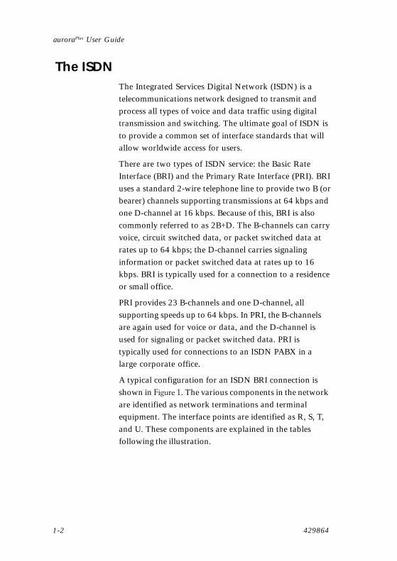
The ISDNThe Integrated Services Digital Network (ISDN) is atelecommunications network designed to transmit andprocess all types of voice and data traffic using digitaltransmission and switching. The ultimate goal of ISDN isto provide a common set of interface standards that willallow worldwide access for users.
There are two types of ISDN service: the Basic RateInterface (BRI) and the Primary Rate Interface (PRI). BRIuses a standard 2-wire telephone line to provide two B (orbearer) channels supporting transmissions at 64 kbps andone D-channel at 16 kbps. Because of this, BRI is alsocommonly referred to as 2B+D. The B-channels can carryvoice, circuit switched data, or packet switched data atrates up to 64 kbps; the D-channel carries signalinginformation or packet switched data at rates up to 16kbps. BRI is typically used for a connection to a residenceor small office.
PRI provides 23 B-channels and one D-channel, allsupporting speeds up to 64 kbps. In PRI, the B-channelsare again used for voice or data, and the D-channel isused for signaling or packet switched data. PRI istypically used for connections to an ISDN PABX in alarge corporate office.
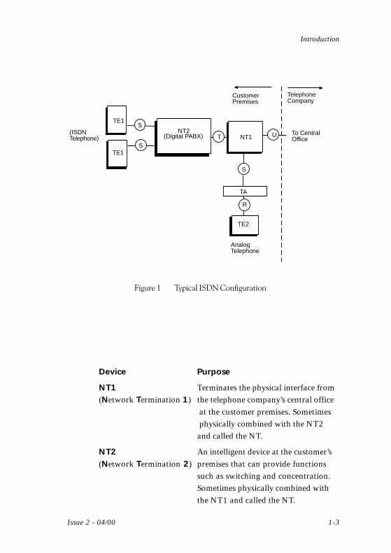
A typical configuration for an ISDN BRI connection isshown in ������. The various components in the networkare identified as network terminations and terminalequipment. The interface points are identified as R, S, T,and U. These components are explained in the tablesfollowing the illustration.
chap01.p65 02/05/00, 15:142
Introduction
Issue 2 - 04/00 1-3
To CentralOfficeNT1
NT2(Digital PABX) UT
TE1
TE1
(ISDNTelephone)
TA
R
TE2
AnalogTelephone
S
S
S
CustomerPremises
TelephoneCompany
�������� ��� ��������������� ����
Device Purpose
NT1 Terminates the physical interface from(Network Termination 1) the telephone company’s central office
at the customer premises. Sometimesphysically combined with the NT2and called the NT.
NT2 An intelligent device at the customer’s(Network Termination 2) premises that can provide functions
such as switching and concentration.Sometimes physically combined withthe NT1 and called the NT.
chap01.p65 02/05/00, 15:413

auroraPlus User Guide
1-4 429864
TE1 Equipment, such as an ISDN(Terminal Equipment 1) telephone, that is directly compatible
with ISDN. Up to eight TE1 devicescan be connected to the S-bus.
TE2 Equipment that is not directly(Terminal Equipment 2) compatible with ISDN and that
requires a Terminal Adapter (TA) tointerface with the ISDN network.
TA A device that provides the interface(Terminal Adapter) between the ISDN termination (NT1)
and non-ISDN equipment (TE2).
Interface Purpose
R Defines the interface between the TE2and the TA.
S Defines the interface between the NT1and the TA or between the NT2 andthe TE1. When the NT1 and NT2 arecombined, referred to as the S/T-interface. The S-bus can support up toeight TE1s.
T Defines the interface between the NT1and the NT2. When the NT1 and NT2are combined, referred to as the S/T-interface.
U Defines the interface at the customerpremises where the central office linefrom the telephone company connectswith the customer’s NT1.
chap01.p65 02/05/00, 15:144

Introduction
Issue 2 - 04/00 1-5
The auroraPlus is designed to test your ISDN network ateither the S-interface (between the user equipment and theNT) or the U-interface (at the demarcation point betweenthe telephone company line and the customer premisesequipment). �������� shows the auroraPlus test points in thesample network.
To CentralOfficeNT1
NT2(Digital PABX) UT
TE1
TE1
(ISDNTelephone)
TA
R
TE2
AnalogTelephone
S
S
S
CustomerPremises
TelephoneCompany
auroraPlus
auroraPlusauroraPlus
�������� ������ ��� ������
chap01.p65 02/05/00, 15:425

auroraPlus User Guide
1-6 429864
Definitions and ExplanationsTo better understand the operation of the auroraPlus, ithelps to understand how different parts of the Basic RateISDN service are identified in operation. The first part ofthis section clarifies the difference between the centraloffice switch that is providing the ISDN service and theD-channel protocol that the switch is using to controlcalls. The next part discusses some important differencesamong frequently confused ISDN terms: TerminalEndpoint Identifier (TEI), Service Profile Identifier (SPID),Directory Number (DN), and B-Channel.
Switch TSwitch TSwitch TSwitch TSwitch Type and Prype and Prype and Prype and Prype and Protocolotocolotocolotocolotocol
ISDN users and technicians often confuse the type ofcentral office switch that is providing an ISDN servicewith the D-channel protocol that the switch is using tocontrol calls. This confusion arises because, when ISDNfirst appeared, each of the major switch vendors offeredits own variation on the standard D-channel protocol.Later, to reduce confusion and to make ISDN servicesmore widely available, the North American telecommuni-cations industry adopted the National ISDN standard toreplace the vendors’ custom protocols. Some of thebehavior of the ISDN circuit and the auroraPlus dependsspecifically on switch type and applies whether the switchis using the National ISDN protocol or a custom protocol.
A circuit’s ����������� is simply the make and model of thecentral office switch providing the ISDN service. InNorth America, the most frequently used brands ofcentral office switches are the AT&T 5ESS and theNortel DMS 100.
chap01.p65 02/05/00, 15:146

Introduction
Issue 2 - 04/00 1-7
The ���������used on an ISDN circuit is the specific set ofmessages and procedures used on the D-channel tocontrol calls. Three major variations of the D-channelprotocol are used in North America: the National ISDNprotocol, the AT&T Custom protocol, and the NortelCustom protocol. The AT&T and Nortel Customprotocols run on AT&T and Nortel switches, respec-tively; the National ISDN protocol can run on any type ofswitch. The AT&T Custom protocol uses two differentconnection modes: point-to-point (PP) and point-to-multipoint (PMP).
Addresses and Identifiers in Basic Rate ISDNAddresses and Identifiers in Basic Rate ISDNAddresses and Identifiers in Basic Rate ISDNAddresses and Identifiers in Basic Rate ISDNAddresses and Identifiers in Basic Rate ISDN
Because it must support the wide range of services andfeatures that ISDN offers, the Basic Rate Interface isfairly complex. First of all, the interface is divided intothree channels. The two B-channels carry only the user’svoice or data calls. The D-channel carriesthe signaling messages that control calls on theB-channels; it can also carry low-speed packet switched(X.25) data communications.
Some additional complexity arises because the ISDNBasic Rate Interface is designed to support more than onedevice at a time. The S-interface, described earlier, is abus that can connect up to eight different devices(telephones, fax machines, computers, data terminals,etc.) to the Basic Rate Interface (although only two ofthem can be active at once). The central office switchneeds to be able to distinguish between the differentdevices so it can direct calls to specific devices. Theswitch also needs to be able to restrict the services it isoffering to the set of services that the user has actuallyordered.
chap01.p65 02/05/00, 15:147

auroraPlus User Guide
1-8 429864
SerSerSerSerService Prvice Prvice Prvice Prvice Profiles and SPIDsofiles and SPIDsofiles and SPIDsofiles and SPIDsofiles and SPIDs
The ��������������� of a BRI service is a record in a database that the central office switch uses to determine howto serve a specific customer and how to handle specificcommands and requests (such as feature keys) from apiece of Customer Premises Equipment. In most cases,when BRI services are provisioned, each terminal deviceon the service receives one or more Service ProfileIdentifiers (SPIDs) that identify the service profilesassigned to the service. (Circuits using the AT&T Customprotocol with point-to-point connection type do not useservice profiles and, therefore, have no SPIDs.) The SPIDusually includes the service’s directory number and someadditional digits of information.
The ISDN user receives a written copy of the SPIDs forhis BRI service from the service provider. The TE devicemust be programmed with SPIDs in order to initializeLayer 3, and subsequently place ISDN calls. Dependingupon the software revision active in the switch and in theTE, the TE either requests SPIDs from the switch orsubmits pre-programmed SPIDs to the switch.
When the auroraPlus initializes, it sends a message to theswitch requesting the SPIDs for the line. If the switchdoes not respond, the auroraPlus then tries to ‘guess’ theSPIDs for the line based on the values resident in non-volatile memory. The contents of SPID1 and SPID2 areassumed to be directory numbers, and are used with theNational ISDN SPID Simplification rules to derive SPIDnumbers and submit them to the switch.
Some ISDN switches (such as the 5ESS) can connectmultiple B-channel calls with only one SPID. Others, suchas some versions of the Nortel DMS 100, require aseparate SPID for each active call. Note that this featuredepends on switch type and not on protocol.
chap01.p65 02/05/00, 15:148

Introduction
Issue 2 - 04/00 1-9
TEITEITEITEITEI
The Terminal Endpoint Identifier (TEI) is a portion of theaddress that identifies a device on the D-channel for callcontrol signaling. From the viewpoint of the signalingprotocol, a �� �������!������can be an actual, physicalterminal, or it can be a logical entity associated with partof a basic rate service. Whenever a BRI service isinitialized (i.e, turned up), the switch assigns one or moreTEIs to the circuit. In North American ISDN, a TEI isuniquely associated with a service profile (i.e., one TEI isassigned per SPID). In some instances, a specific servicerequires that a specific fixed TEI be assigned. D-channelX.25 service on a Nortel switch is an example of this.
When a terminal device such as the auroraPlus begins toturn up the interface, it requests a TEI assignment andthen transmits its SPID over the data link associated withthat TEI for verification. (For a second Service Profile, itrepeats the process and receives another TEI.) Forterminals or services that use a fixed TEI, the terminalsimply tells the switch which TEI will be used formessages for that service.
A BRI service can have one or more !���������� "���#These are the ordinary telephone numbers used to dialthat service from the outside. Customers and techniciansoften confuse the directory number with the SPID. Thedirectory number is usually part of the SPID, but theSPID usually contains additional digits.
B-ChannelB-ChannelB-ChannelB-ChannelB-Channel
A B-channel on a BRI service is one of two 64 kbpsdigital channels available for voice or data calls. In mostcases, specific B-channels are not associated with specificdirectory numbers or SPIDs. This allows the central officeto assign an incoming or outgoing call for an ISDNservice dynamically to the first available B-channel.
chap01.p65 02/05/00, 15:149

auroraPlus User Guide
1-10 429864
chap01.p65 02/05/00, 15:1410
Issue 2 - 04/00 2-1
A Look at Your auroraPlus
A Look at Your auroraPlus
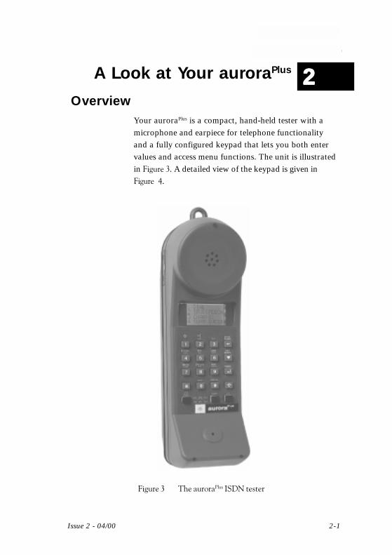
OverviewYour auroraPlus is a compact, hand-held tester with amicrophone and earpiece for telephone functionalityand a fully configured keypad that lets you both entervalues and access menu functions. The unit is illustratedin �����$. A detailed view of the keypad is given in����%&.
�����$ �����������������������
22222
chap02.p65 02/05/00, 15:141
2-2 429864
auroraPlus User Guide
2 3
87 9
4 5 6
▲
0 #
OPER
POTS CHK
STATUS
TERM S/U
ABC DEFHOMEFLASH
B CHANGHI
2BCHKPQRS
SRV CHKTUV
SPIDJKL
EXITREDIAL
LOOPMNO
BERTWXYZ HOOK
1
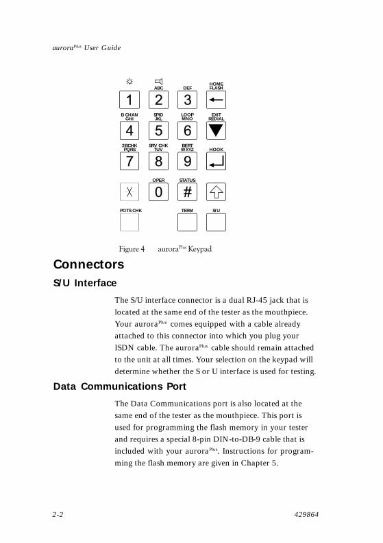
�����& ���������'����!
ConnectorsS/U Interface
The S/U interface connector is a dual RJ-45 jack that islocated at the same end of the tester as the mouthpiece.Your auroraPlus comes equipped with a cable alreadyattached to this connector into which you plug yourISDN cable. The auroraPlus cable should remain attachedto the unit at all times. Your selection on the keypad willdetermine whether the S or U interface is used for testing.
Data Communications Port
The Data Communications port is also located at thesame end of the tester as the mouthpiece. This port isused for programming the flash memory in your testerand requires a special 8-pin DIN-to-DB-9 cable that isincluded with your auroraPlus. Instructions for program-ming the flash memory are given in Chapter 5.
chap02.p65 02/05/00, 15:142

Issue 2 - 04/00 2-3
A Look at Your auroraPlus
Battery Charger
The 9-12 VDC battery charger connector is locatedabove the S/U interface connector.
NOTE
You must charge the battery before using the auroraPlus
under battery power for the first time. The battery takesapproximately two hours to receive a full charge. Pleaserefer to the section ������later in this chapter for completeinstructions on charging the battery.
Switches and KeysThere are two switches on the sides of the auroraPlus andthree switches on the bottom row of the keypad. (Whenthe switches on the bottom row of the keypad are pressed[= on], the white border is not visible. When they are notpressed [= off], the border is visible.) These switches aredescribed below.
Switch Name Function
ISDN Selects either the ISDN or optionalANALOG/POTS analog test interface.
CHARGE/BAT Determines the source of power forthe auroraPlus. See the section �����later in this chapter for more details.
LINE MON Activates the line monitoring functionwhen pressed. This function allowsthe auroraPlus to listen, but nottransmit, when connected to atelephone line via the U-interface.
TERM Correct operation on the S-busrequires that the customer premiseswiring be terminated with 100 Ohmsat both ends in both directions. Ifyour S-bus is not terminated this way,the auroraPlus can provide thistermination when this switch ispressed.
chap02.p65 02/05/00, 15:143

2-4 429864
auroraPlus User Guide
S/U Determines whether testing will occuron the U-interface (switch presseddown; white border not visible) or S-interface (switch up; white bordervisible).
The keys on the auroraPlus keypad are described below.The keypad indicates each key’s function above the key.Blue labels indicate the key’s normal function. Yellowlabels indicate the key’s function when the Shift key ispressed first. White labels indicate functionality that isavailable when the tester is in analog mode.
Dialing Used for entering digits, as from a
(0…9, *, #) standard telephonekeypad.
Enter (Hook) Used to confirm user entry fromcertain screens. Allows for togglingbetween the Menu system and the callstatus screen. Also acts as the Hookkey during call setupsequences.
Scroll Pages to the next screen for menusthat consist of more than one screen.Repeated pressing of the Scroll keycircles through the screens. In analogmode, acts as a Redial key.
Clear (Flash) Clears any entered digits from right toleft, one digit at a time. In analogmode, acts as a Flash key.
Shift Provides extended menu navigationfunctions in ISDN and analog mode.For extended menu navigationfunctions, press the Shift key and thenthe second key; you do not need tohold the Shift key down when youpress the second key. (A backlighted Swill appear in the lower right corner ofthe display to indicate that the Shiftkey is active.) Shift key combinationsare indicated on the auroraPlus keypadin yellow and are explained below:
chap02.p65 02/05/00, 15:144
Issue 2 - 04/00 2-5
A Look at Your auroraPlus
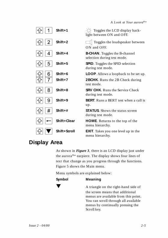
Shift+1 Toggles the LCD display back-light between ON and OFF.
Shift+2 Toggles the loudspeaker between
ON and OFF.
Shift+4 B-CHAN. Toggles the B-channelselection during test mode.
Shift+5 SPID. Toggles the SPID selectionduring test mode.
Shift+6 LOOP. Allows a loopback to be set up.
Shift+7 2BCHK. Runs the 2B Check duringtest mode.
Shift+8 SRV CHK. Runs the Service Checkduring test mode.
Shift+9 BERT. Runs a BERT test when a call isup.
Shift+# STATUS. Shows the status screenduring test mode.
Shift+Clear HOME. Returns to the top of themenu hierarchy.
Shift+Scroll EXIT. Takes you one level up in themenu hierarchy.
Display AreaAs shown in Figure 3, there is an LCD display just underthe auroraPlus earpiece. The display shows four lines oftext that change as you progress through the functions.Figure 5�shows the Main menu.
Menu symbols are explained below:
Symbol Meaning
▼ A triangle on the right-hand side ofthe screen means that additionalmenus are available from this point.You can scroll through all availablemenus by continually pressing theScroll key.
chap02.p65 02/05/00, 15:155

2-6 429864
auroraPlus User Guide
S A reversed S in the lower right-hand
corner means that the shift key hasbeen activated and the unit is waitingfor you to press a second key.
1, 2, 3 ... The numbers indicate choices you canmake to go to another screen.
0 The 0 lets you exit from a screenwithout saving changes.
* In screens that let you choose frommore than one option, an asteriskindicates the currently selected option.
1 CALLS2 TESTS3 RESULTS4 SETUP s
Triangleindicatingadditionalscreens
Reversed S
Numberedchoices
Figure 5 Display Area
A complete hierarchy of menus can be found in Appen-dix A.
PowerYour auroraPlus can be powered from the built-in batteryfor U-interface, S-interface, or POTS testing. To receivepower from the battery during ISDN U- or S-interfacetesting or during analog testing, set the charging switch toBat.
If the battery needs recharging, follow the procedurebelow:
Warning
Use only the battery charger/AC converter that wasshipped with your auroraPlus tester. The use of any otherpower supply may damage the tester and will void thewarranty.
chap02.p65 02/05/00, 15:156
Issue 2 - 04/00 2-7
A Look at Your auroraPlus
1 Insert the termination of the supplied AC adapter/charger into the 9-12 VDC connector on theauroraPlus and plug the adapter end into a walloutlet.
2 Switch the Charge/Bat switch to Charge.
3 The red Charge LED lights. When the battery isfully charged, the LED starts to flash.
NOTE
To avoid accidentally discharging the battery,always set the charging switch to Charge when theauroraPlus is not in use.
Line Voltage
When you initialize your auroraPlus to check the S- or U-interface, the display indicates the voltage on the line youare using. This is indicated as PS2 on the S-interface. Onthe U-interface, the voltage is indicated as LINE. You canalso display the voltage from the Status screens (seeChapter 5).
chap02.p65 02/05/00, 15:157

2-8 429864
auroraPlus User Guide
chap02.p65 02/05/00, 15:158
Issue 2 - 04/00 3-1
Testing with Your auroraPlus
3Testing with Your auroraPlus
U-Interface Turn-up and Service CheckYou can use the U-interface turn-up and service checkdescribed below to check newly installed circuits. This testshows that the circuit can be initialized and then deter-mines which services are available on your ISDN connec-tion for outgoing calls, letting you verify that you receivedthe services you ordered. The test consists of four basicsteps:
• Making the connection to the interface
• Selecting the protocol and connection mode
• Programming the required SPIDs
• Initiating the service check
To set up the test, you will need to know how your ISDNconnection is provisioned, including the type of centraloffice switch, the ISDN protocol (AT&T, National ISDN,or Northern Telecom), and the connection type (point-to-point or point-to-multipoint) used on the circuit undertest.
Use the following steps to initialize and test the line:
1 Make sure that the S/U switch on the keypad is in the“down” (U) position.
2 Set the ISDN/Analog POTS switch to ISDN.
3 Connect the appropriately terminated U-interfacecord from the auroraPlus to the ISDN U-interfaceconnector of the circuit under test.
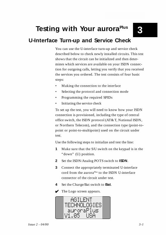
4 Set the Charge/Bat switch to Bat.
✔✔✔✔✔ The Logo screen appears.
AGILENTTECHNOLOGIESauroraPlus
V1.05 USA
chap03.p65 02/05/00, 15:151
auroraPlus User Guide
3-2 429864
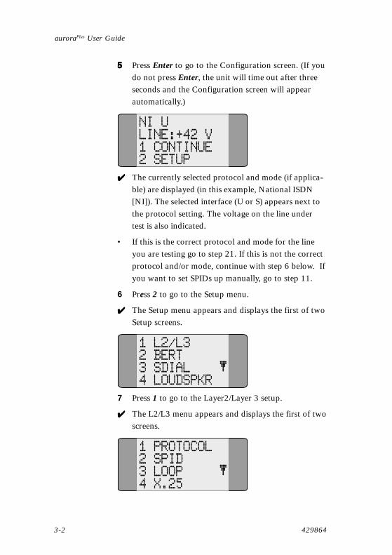
55555 Press Enter to go to the Configuration screen. (If youdo not press Enter, the unit will time out after threeseconds and the Configuration screen will appearautomatically.)
NI ULINE:+42 V1 CONTINUE2 SETUP
✔✔✔✔✔ The currently selected protocol and mode (if applica-ble) are displayed (in this example, National ISDN[NI]). The selected interface (U or S) appears next tothe protocol setting. The voltage on the line undertest is also indicated.
• If this is the correct protocol and mode for the lineyou are testing go to step 21. If this is not the correctprotocol and/or mode, continue with step 6 below. Ifyou want to set SPIDs up manually, go to step 11.
6 Press 2 to go to the Setup menu.
✔✔✔✔✔ The Setup menu appears and displays the first of twoSetup screens.
1 L2/L32 BERT3 SDIAL4 LOUDSPKR
7 Press 1 to go to the Layer2/Layer 3 setup.
✔✔✔✔✔ The L2/L3 menu appears and displays the first of twoscreens.
1 PROTOCOL2 SPID3 LOOP4 X.25
chap03.p65 02/05/00, 15:152

Issue 2 - 04/00 3-3
Testing with Your auroraPlus
8 • If the protocol or mode that you saw in step 5 wasincorrect, press to configure the protocol.• If the protocol and mode were correct and youwant to set SPIDs up manually or have the auroraPlus
guess the SPID(s), go to step 10.
• If:
- the protocol and mode were correct- you have not set SPID(s) up manually- the line you are testing supports AutoSPIDS- you want auroraPlus to set the SPIDs upautomatically go to step 20.
✔✔✔✔✔ The Protocol menu appears and displays the first oftwo screens.
1*NI2 NORT3 AT&T PMP4 AT&T PP
(The second screen contains only the 0 Exitoption.)
9 Press 1 (NI) if your protocol is National ISDN.Press 2 (NORT) if your protocol is NorthernTelecom.Press 3 (AT&T-PMP) if your protocol is AT&T andyour mode is point-to-multipoint.Press 4 (AT&T-PP) if your protocol is AT&T andyour mode is point-to-point.
✔✔✔✔✔ An asterisk marks your selection.
1010101010 Press the Enter key to return to the L2/L3 menu.
1 PROTOCOL2 SPID3 LOOP4 X.25
chap03.p65 02/05/00, 15:153

auroraPlus User Guide
3-4 429864
In North America, the switch uses a SPID to identifywhich software features a piece of terminal equipment hasaccess to. Upon Layer 3 initialization, auroraPlus attemptsto poll the switch for SPID numbers registered to thatinterface. If the switch does not respond (indicating that itis not AutoSPID capable) the auroraPlus then tries to‘guess’ the SPID(s) for the line using the values in theSPID1 and SPID 2 registers as the basis for the calcula-tion.
To configure the SPID(s) manually:
NOTE
SPIDS are used on a BRI service in point-to-multipoint mode. If you are using the AT&Tprotocol in point-to-point mode, a SPID is notrequired and will not be transmitted even if you enterone. In this case, you can skip to step 20.
Steps 11 through 19 explain how to program theSPIDs manually if you know them.
If you do not know the SPIDs, use this procedure tofill in the 10 digit DN(s) for the line in place of theSPIDs. When connected, auroraPlus will attempt to useAutoSPID. If this fails, auroraPlus will use the DNs youhave entered to automatically derive and submit theSPIDs. If this ‘guessing’ algorithm fails, you mustenter the SPIDs manually.
11 Press 2 (SPID) to access the SPID menu.
✔✔✔✔✔ The SPID menu appears.
1 SPID12 SPID20 EXIT
chap03.p65 02/05/00, 15:154

Issue 2 - 04/00 3-5
Testing with Your auroraPlus
12 Press 1 (SPID1) to program the first SPID.
✔✔✔✔✔ The SPID is displayed if one has already beenconfigured. If a SPID has not yet been configured, thedisplay will be blank.
13 If a SPID has already been configured and is dis-played, press the Clear key to delete it one digit at atime.
14 Enter the new SPID using the numeric keypad.
NOTE
You need enter only the 10 digit directory number. Ifthe switch is not AutoSPID capable, auroraPlus willadd known prefixes and suffixes to this number untila correct response is received from the switch. If allSPID possibilities have been tried unsuccessfully, amessage to this effect will appear during initialization,and you will need to enter the SPID(s) manually.
15 Press the Enter key to confirm your entry.
✓✓✓✓✓ You return to the SPID menu.
1 SPID12 SPID20 EXIT
• If you need to enter a second SPID, continue withstep 16.
• If you do not need to enter another SPID, go tostep 20.
chap03.p65 02/05/00, 15:155

auroraPlus User Guide
3-6 429864
To enter a second SPID:
16 Enter 2 (SPID2) to program the second SPID.
✔✔✔✔✔ The second SPID is displayed if one has already beenconfigured. If a second SPID has not yet beenconfigured, the display will be blank.
17 If a SPID has already been configured and is dis-played, press the Clear key to delete it one digit at atime.
18 Enter the new SPID using the numeric keypad.
19 Press the Enter key to confirm your entry.
✔✔✔✔✔ You return to the SPID menu.
1 SPID12 SPID20 EXIT
Continue with the procedure to initialize the circuit:
20 Press Shift+Clear to return to the Configurationscreen.
NI ULINE:+42 V1 CONTINUE2 SETUP
21 Press 1 to begin the circuit initialization.
✔✔✔✔✔ The Initialization message appears. The screen alsoindicates the status of Layers 1, 2, and 3 with up anddown arrows.
InitializingU Interfaceplease waitL1 L2 L3
chap03.p65 02/05/00, 15:156

Issue 2 - 04/00 3-7
Testing with Your auroraPlus
The U-interface can take over one minute to initialize, andduring this time the screen will display the initializingmessage and indicate the status of layers 1, 2, and 3 witharrows. When the physical layer of the interface becomesactive, the tester will briefly display a layer 1 statusmessage and you will see L1↑ at the bottom of the screen.This indicates that the physical circuit is workingcorrectly.
When the data link layer of the interface becomes active(i.e., when the switch has assigned TEIs to the auroraPlus),the tester will display a Layer 2 status message and youwill see L2↑ at the bottom of the screen.
auroraPlus then sends a message to the switch to requestthe SPIDs for the line.
InitiatingAuto SPID
L1 L2 L3
If the switch fails to send the SPIDs auroraPlus starts togenerate SPIDs to ‘guess’ the SPIDs of the line.
1st attemptSPID1 guess
L1 L2 L3
When the signaling protocol becomes active and theswitch has accepted the first SPID, the tester will displaySPID 1 OK (and possibly SPID 2 OK) and you see L3↑ .
This progression of messages layer through three stagesof layer activation can provide important diagnosticinformation if the circuit fails to initialize. When theinitialization is complete, the IDLE message appears. Thissequence of messages is an important diagnostic aid inensuring that the ISDN line initializes properly.
chap03.p65 02/05/00, 15:157

auroraPlus User Guide
3-8 429864
Idle
L1 L2 L3
NOTE
While initializing the U-interface, the switch transmits afew control messages over the Embedded OperationsChannel (EOC). The auroraPlus displays these messages asthey are received. You can access this information underthe Status display.
If there is a problem:
• If you do not see L1↑ (layer 1 up) after about twominutes, one of the following conditions applies:
• The S/U selector button on the auroraPlus is inthe wrong position.
• The cable from the auroraPlus is not connectedto the ISDN circuit.
• There is no ISDN service on the circuit.
• If you have set up the tester correctly, but it still doesnot display L1↑ after approximately three minutes,the physical layer of the circuit has failed and must berepaired before any further initialization or testing ispossible.
• If the tester displays L1↑ but shows L2↓ afterapproximately three minutes, the switch and thetester have failed to establish a data link; thisindicates a probable hardware failure in the switch. Ifthe message L2 TEI err appears, this provides apositive indication of a failure at layer 2.
• If the tester displays L2↑ but fails either to accept orreject the first SPID within a few minutes, it displaysSPID1 timed out, check setup. This indicates atimeout for the SPID acceptance, which usually meansfailure in the switch.
chap03.p65 02/05/00, 15:158

Issue 2 - 04/00 3-9
Testing with Your auroraPlus
• If the switch does not accept any of the SPIDs sent byauroraPlus the message SPID1 Err is displayed.
The Idle screen is then displayed with Layer 3 down:
Idle
L1 L2 L3
You can now start the service check:
22 To select the service profile (i.e., the SPID to use forthe service check), press Shift+5 while the testerdisplays IDLE. The display will toggle between USESPID1 and USE SPID2. The auroraPlus will use thecorresponding SPID for performing the service check.
23 To select the B-channel to be checked, press Shift+4.(You must be in the menu system to do this.)
✔✔✔✔✔ The B-Channel Select menu appears.
1*B12 B23 BX0 EXIT
NOTE
You can run the service check against the entire BRIservice (by selecting BX from the Channel Selectmenu) or against either of the two B-channels (byselecting either B1 or B2). When you select BX (thefactory default), the results may apply to the entireservice, or to only one of the B-channels, dependingon the way in which the circuit has been provisioned.
24 Press 1, 2, or 3 to make your B-Channel selectionand then Enter.
✔✔✔✔✔ An asterisk marks your selection and the displayreturns to the previous screen.
chap03.p65 02/05/00, 15:159
auroraPlus User Guide
3-10 429864
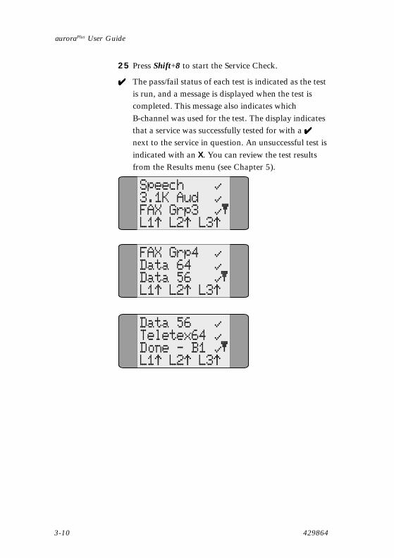
25 Press Shift+8 to start the Service Check.
✔✔✔✔✔ The pass/fail status of each test is indicated as the testis run, and a message is displayed when the test iscompleted. This message also indicates whichB-channel was used for the test. The display indicatesthat a service was successfully tested for with a ✔✔✔✔✔next to the service in question. An unsuccessful test isindicated with an X. You can review the test resultsfrom the Results menu (see Chapter 5).
Speech3.1K AudFAX Grp3L1 L2 L3
FAX Grp4Data 64Data 56L1 L2 L3
Data 56Teletex64Done - B1L1 L2 L3
chap03.p65 02/05/00, 15:1510

Issue 2 - 04/00 3-11
Testing with Your auroraPlus
The auroraPlus tests for the following service types:
• Speech: ISDN voice
• 3.1K Aud: analog (3.1 kHz) voice
• FAX Grp3: Group 3 (analog) facsimile
• FAX Grp4: Group 4 (digital) facsimile
• Data 64: 64 kbps data
• Data 56: 56 kbps data
• Teletex64: 64 kbps Teletex
26 Press Enter to terminate the test and go to the Mainmenu.
chap03.p65 02/05/00, 15:1511
auroraPlus User Guide
3-12 429864
Testing the S-InterfaceThe S-interface test verifies the ISDN line from thecustomer’s side of the NT1 between the NT1 and theTerminal Equipment (see Figure 2). The test is similar tothe U-interface test described in the previous section. Likethe U-interface test, the S-interface test also has differentprocedures for circuits with only one SPID and circuitswith two SPIDs.
1 Make sure that the S/U switch on the keypad is in the“up” (S) position.
2 Set the ISDN/Analog POTS switch to ISDN.
3 Connect the line from the connector on yourauroraPlus to the S-interface on the NT1 using theRJ-45-to-RJ-45 cable provided.
4 Set the Charge/Bat switch to BAT.
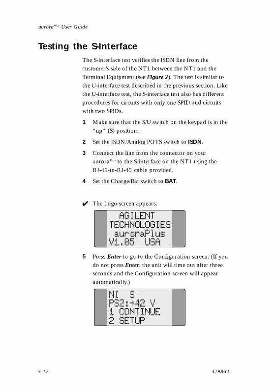
✔✔✔✔✔ The Logo screen appears.
AGILENTTECHNOLOGIESauroraPlus
V1.05 USA
5 Press Enter to go to the Configuration screen. (If youdo not press Enter, the unit will time out after threeseconds and the Configuration screen will appearautomatically.)
NI SPS2:+42 V1 CONTINUE2 SETUP
chap03.p65 02/05/00, 15:1512

Issue 2 - 04/00 3-13
Testing with Your auroraPlus
✔✔✔✔✔ The currently selected protocol and mode (if applica-ble) are displayed (in this example, National ISDN[NI]). The selected interface (in this case, S) appearsnext to the protocol setting. The voltage on the linefor PS2.
6 • If this is the correct protocol and mode for the lineyou are testing and your SPIDs have already beenconfigured, continue with step 7 below.
• If you have not already configured the protocol,connection mode, or SPIDs, go to step 6 of theU-Interface Turn Up and Service Check proce-dure earlier in this chapter.
7 Press 1 to start the circuit initialization.
✔✔✔✔✔ The Initialization message appears. The screendisplays the messages L1 Active, L2 Active, andarrows at the bottom of the screen display the L1, L2,and L3 status.
You see the messages SPID 1 OK, SPID 2 OK (if youare using two SPIDs) and then IDLE. This indicatesthat layer 3 is working, and the S-interface initializa-tion is complete. You can now perform the ServiceCheck described in steps 22 through 26 of theprevious section.
chap03.p65 02/05/00, 15:1513

auroraPlus User Guide
3-14 429864
D-Channel Packet (X.25) TestThe test described in this section verifies the presence of acorrectly operating D-channel packet service on your BRIcircuit. The test consists of four basic steps:
• Making the connection to the interface
• Configuring for protocol, connection mode, andSPIDs
• Configuring parameters for the X.25 line
• Initiating the X.25 call
To set up the test, you must know the following informa-tion about the X.25 line so that you can configure theparameters properly:
• The logical channel (LCN) on which the call is tobe sent
• Whether or not a Closed User Group (CUG) isto be used
• Whether or not a specific Recognized PrivateOperating Agency (RPOA) is to be used
• Whether or not the reverse charging facility is to beused
If you are not familiar with these parameters, or do notknow how to configure them for your X.25 line, contactyour X.25 service provider.
If you have not set up the connection, interface,or SPIDs, start here:
1 • To set up the test to run on the U-interface,follow steps 1 through 5 of the U-InterfaceTurn-up and Service Check earlier in thischapter.
• To set up the test to run on the S-interface,follow steps 1 through 5 of the procedureTesting the S-Interface earlier in this chapter.
chap03.p65 02/05/00, 15:1514

Issue 2 - 04/00 3-15
Testing with Your auroraPlus
2 If the correct protocol and connection mode have notyet been set up, follow steps 6 through 10 of theU-Interface Turn-up and Service Check earlier in thischapter.
3 If the correct SPIDs have not yet been entered andyou want to enter them manually, follow steps 11through 21 of the U-Interface Turn-up and Service
Check earlier in this chapter.
4 If the circuit has not been initialized, follow step 22 ofthe U-Interface turn-up or step 7 of theS-Interface test procedure.
If the preliminary configuration has been done(connection, interface, and SPIDs) and the circuitinitialized, start here:
5 From the Main menu, press 4 to access the Setupmenu.
✔✔✔✔✔ The first screen of the Setup menu appears.
1 L2/L32 BERT3 SDIAL4 LOUDSPKR
6 Press 1 to access the Layer 2/Layer 3 setup.
✔✔✔✔✔ The first screen of the Layer 2/Layer 3 menu appears.
1 PROTOCOL2 SPID3 LOOP4 X.25
0 EXIT
chap03.p65 02/05/00, 15:1515

auroraPlus User Guide
3-16 429864
7 Press 4 to access the X.25 configuration.
✔✔✔✔✔ The X.25 menu appears and displays the currentlyconfigured values for an X.25 call.
1 LCN:0012 CUG:None3 RPOA:None4 REVC:Off
5 TEI:DYN0 EXIT
This screen shows that Logical Channel Number(LCN) 1 will be used for the call, no Closed UserGroup (CUG) or Recognized Private OperatingAgency (RPOA) has been configured, ReverseCharging (REVC) is off, and a dynamic TEI will beused.
By default, your auroraPlus is configured to usedynamic TEIs; however, X.25 testing may require theuse of a fixed TEI. When a fixed TEI is configured,SPID2 is not used and is not available for any othertest function.
8 Enter 1 to change the Logical Channel Number.
✔✔✔✔✔ The LCN screen appears.
LCN:001
Values from1 to 127
9 Use the numeric keypad to enter the LCN that youwant to use (1-127) followed by Enter.
✔✔✔✔✔ You return to the X.25 menu.
1 LCN:0012 CUG:None3 RPOA:None4 REVC:Off
chap03.p65 02/05/00, 15:1516
Issue 2 - 04/00 3-17
Testing with Your auroraPlus
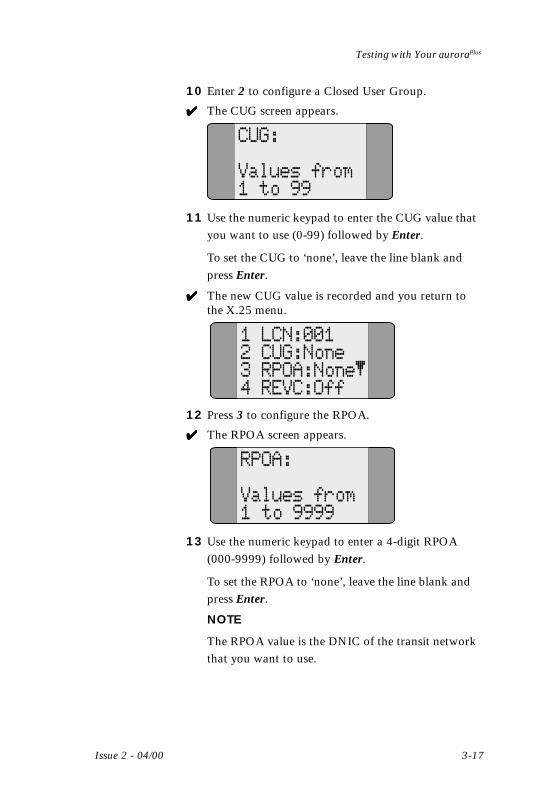
10 Enter 2 to configure a Closed User Group.
✔✔✔✔✔ The CUG screen appears.
CUG:
Values from1 to 99
11 Use the numeric keypad to enter the CUG value thatyou want to use (0-99) followed by Enter.
To set the CUG to ‘none’, leave the line blank andpress Enter.
✔✔✔✔✔ The new CUG value is recorded and you return tothe X.25 menu.
1 LCN:0012 CUG:None3 RPOA:None4 REVC:Off
12 Press 3 to configure the RPOA.
✔✔✔✔✔ The RPOA screen appears.
RPOA:
Values from1 to 9999
13 Use the numeric keypad to enter a 4-digit RPOA(000-9999) followed by Enter.
To set the RPOA to ‘none’, leave the line blank andpress Enter.
NOTE
The RPOA value is the DNIC of the transit networkthat you want to use.
chap03.p65 02/05/00, 15:1517

auroraPlus User Guide
3-18 429864
✔✔✔✔✔ The new RPOA value is recorded and you return tothe X.25 menu.
1 LCN:0012 CUG:None3 RPOA:None4 REVC:Off
14 Press 4 to change the Reverse Charging value.
✔✔✔✔✔ The Reverse Charging screen appears, indicating ifReverse Charging is currently ON or OFF.
1 ON2*OFF0 EXIT
15 Select 1 to turn Reverse Charging ON, or 2 to turn itOFF, followed by Enter.
✔✔✔✔✔ An asterisk marks your selection, and you return tothe X.25 menu.
1 LCN:0012 CUG:None3 RPOA:None4 REVC:Off
16 If you need to configure a fixed TEI, press 5.
✔✔✔✔✔ The TEI screen appears.
1 DYNAMIC2 FIXED0 EXIT
*
17 Press 2 to enter the fixed TEI.
TEI:
Values from0 to 63
chap03.p65 02/05/00, 15:1518
Issue 2 - 04/00 3-19
Testing with Your auroraPlus
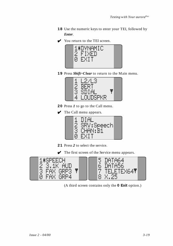
18 Use the numeric keys to enter your TEI, followed byEnter.
✔✔✔✔✔ You return to the TEI screen.
1 DYNAMIC2 FIXED0 EXIT
*
19 Press Shift+Clear to return to the Main menu.
1 L2/L32 BERT3 SDIAL4 LOUDSPKR
20 Press 1 to go to the Call menu.
✔✔✔✔✔ The Call menu appears.
1 DIAL2 SRV:Speech3 CHAN:B10 EXIT
21 Press 2 to select the service.
✔✔✔✔✔ The first screen of the Service menu appears.
1*SPEECH2 3.1K AUD3 FAX GRP30 FAX GRP4
5 DATA646 DATA567 TELETEX648 X.25
(A third screen contains only the 0 Exit option.)
chap03.p65 02/05/00, 15:1519

auroraPlus User Guide
3-20 429864
22 Press 8 and then Enter to select X.25 as your servicetype.
NOTE
You do not have to go to the second screen for 8 tobe a valid selection.
✔✔✔✔✔ The auroraPlus returns to the Call menu.
1 DIAL2 SRV:Speech3 CHAN:B10 EXIT
NOTE
When you select X.25 as your outbound service type, thechannel selection is automatically set to the D-channel.
23 Press 1 to go to the Dial screen.
✔✔✔✔✔ The Dial screen appears. The most recently dialednumber appears.
NUM:7035551212
24 Use the numeric keys to enter the destination numberon the packet network. The number can have up to15 digits.
✔✔✔✔✔ Once the call is connected, the display showsConnect and the number you dialed.
Connect X.257035551212
L1 L2 L3
A second screen shows how many packets have beensent and received. You can cause packets to betransmitted by pressing 1. As you do so, you will see
chap03.p65 02/05/00, 15:1520
Issue 2 - 04/00 3-21
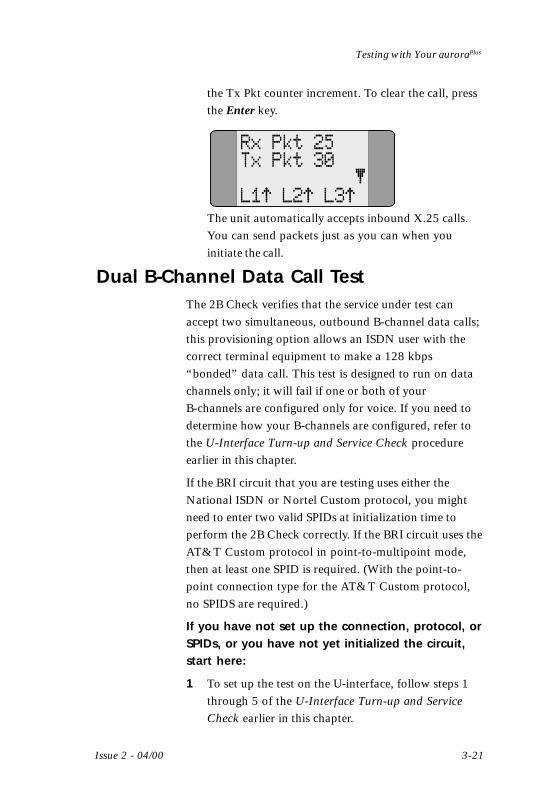
Testing with Your auroraPlus
the Tx Pkt counter increment. To clear the call, pressthe Enter key.
Rx Pkt 25Tx Pkt 30
L1 L2 L3The unit automatically accepts inbound X.25 calls.You can send packets just as you can when youinitiate the call.
Dual B-Channel Data Call TestThe 2B Check verifies that the service under test canaccept two simultaneous, outbound B-channel data calls;this provisioning option allows an ISDN user with thecorrect terminal equipment to make a 128 kbps“bonded” data call. This test is designed to run on datachannels only; it will fail if one or both of yourB-channels are configured only for voice. If you need todetermine how your B-channels are configured, refer tothe U-Interface Turn-up and Service Check procedureearlier in this chapter.
If the BRI circuit that you are testing uses either theNational ISDN or Nortel Custom protocol, you mightneed to enter two valid SPIDs at initialization time toperform the 2B Check correctly. If the BRI circuit uses theAT&T Custom protocol in point-to-multipoint mode,then at least one SPID is required. (With the point-to-point connection type for the AT&T Custom protocol,no SPIDS are required.)
If you have not set up the connection, protocol, orSPIDs, or you have not yet initialized the circuit,start here:
1 To set up the test on the U-interface, follow steps 1through 5 of the U-Interface Turn-up and ServiceCheck earlier in this chapter.
chap03.p65 02/05/00, 15:1521

auroraPlus User Guide
3-22 429864
2 If the correct protocol and connection mode have notyet been set up, follow steps 6 through 10 of theU-Interface Turn-up and Service Check earlier in thischapter.
3 If the correct SPIDs have not yet been entered, andyou want to enter them manually, follow steps 11through 21 of the U-Interface Turn-up and Service
Check earlier in this chapter.
4 If the circuit has not yet been initialized, follow step22 of the U-Interface Turn-up and Service Check
earlier in this chapter.
If the preliminary configuration has been done(connection, protocol, and SPIDs) and the circuithas been initialized, start here:
5 Press Shift+7 to start the 2B Check.
✔✔✔✔✔ The 2B Check screen appears.
B1 Data64B2 Data642B passedL1 L2 L3
This screen displays the test progress. A ✔✔✔✔✔ meansthat the test passed on the designated channel. An Xmeans that the test failed. A — means that the test isin progress on that channel.
A message appears when the test has finished. 2B
Passed means that both B-channels can be usedsimultaneously for outbound data calls, for instancefor a video or IP router application. If the circuit isprovisioned so that it is not possible to complete twosimultaneous B-channel calls (for example, one orboth B-channels are provisioned only for voice) or ifthere is some type of problem on the line, the displayshows 2B Failed.
chap03.p65 02/05/00, 15:1522
Issue 2 - 04/00 3-23
Testing with Your auroraPlus
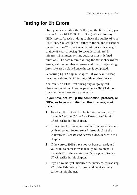
Testing for Bit ErrorsOnce you have verified the SPID(s) on the BRI circuit, youcan perform a BERT (Bit Error Rate) self-call for anyISDN service (speech or data) to check the quality of yourISDN line. You set up a call either to the second B-channelon your auroraPlus or to a remote test device for a lengthof time of your choosing (30 seconds, 1 minute, 5minutes, 15 minutes, continuously, or a user-definedduration). The data received during the test is checked forerrors, and the number of errors and the correspondingerror rate are displayed once the test is completed.
See Setting Up a Loop in Chapter 5 if you want to loopincoming calls for BERT testing with another device.
You can run a BERT test during any outgoing call.However, the test will use the parameters (BERT dura-tion) that have been set up previously.
If you have not set up the connection, protocol, orSPIDs, or have not initialized the interface, starthere:
1 To set up the test on the U-interface, follow steps 1through 5 of the U-Interface Turn-up and ServiceCheck earlier in this chapter.
2 If the correct protocol and connection mode have notyet been set up, follow steps 6 through 10 of theU-Interface Turn-up and Service Check earlier in thischapter.
3 If the correct SPIDs have not yet been entered, andyou want to enter them manually, follow steps 11through 21 of the U-Interface Turn-up and ServiceCheck earlier in this chapter.
4 If you have not yet initialized the interface, follow step22 of the U-Interface Turn-up and Service Checkearlier in this chapter.
chap03.p65 02/05/00, 15:1523
auroraPlus User Guide
3-24 429864
If the preliminary configuration has been done(connection, protocol, and SPIDs) and the interfacehas been initialized, start here:
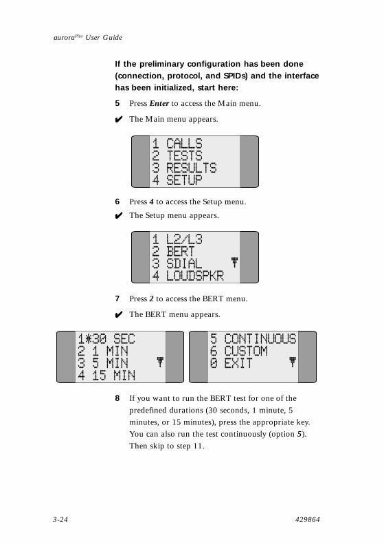
5 Press Enter to access the Main menu.
✔✔✔✔✔ The Main menu appears.
1 CALLS2 TESTS3 RESULTS4 SETUP
6 Press 4 to access the Setup menu.
✔✔✔✔✔ The Setup menu appears.
1 L2/L32 BERT3 SDIAL4 LOUDSPKR
7 Press 2 to access the BERT menu.
✔✔✔✔✔ The BERT menu appears.
1*30 SEC2 1 MIN3 5 MIN4 15 MIN
5 CONTINUOUS6 CUSTOM0 EXIT
8 If you want to run the BERT test for one of thepredefined durations (30 seconds, 1 minute, 5minutes, or 15 minutes), press the appropriate key.You can also run the test continuously (option 5).Then skip to step 11.
chap03.p65 02/05/00, 15:1524

Issue 2 - 04/00 3-25
Testing with Your auroraPlus
3• If you want to customize the length of time theBERT test runs, enter 6.
✔✔✔✔✔ The BERT Custom screen appears.
HR MN0:01
Enter BERTduration
9 From left to right, enter the number of hours andminutes that you want the test to run followed byEnter. (The maximum time you can enter is 3:59.)
✔✔✔✔✔ You return to the Bert menu.
1*30 SEC2 1 MIN3 5 MIN4 15 MIN
10 Press Shift+Clear to return to the Main menu.
✔✔✔✔✔ The Main menu appears.
1 CALLS2 TESTS3 RESULTS4 SETUP
11 Enter 1 to access the Call menu.
✔✔✔✔✔ The Call menu appears.
1 DIAL2 SRV:Speech3 CHAN:B10 EXIT
chap03.p65 02/05/00, 15:1525

auroraPlus User Guide
3-26 429864
12 Press 1.
✔✔✔✔✔ The Dial screen appears.
NUM:7035551212
13 Enter the number that you want to dial. On a circuitwith two SPIDs, enter the directory number associ-ated with SPID2. If you are testing a circuit from anAT&T central office switch (with either AT&TCustom or National ISDN protocol) with only oneSPID, you can select a DATA service (DATA 64 orDATA 56) and complete a BERT self-call to thedirectory number associated with SPID1.
NOTE
The service type can be selected from selection 2 ofthe Call menu. See Chapter 4 for further details.
✓✓✓✓✓ Once the call is connected, a call connected screensimilar to the one below appears. This screen showsthe B channel being used for the call, the type of call,and the number dialed.
Connect B1Data 647035551212L1 L2 L3
If a problem is encountered while the call is beingestablished, the standard messages will be displayed.If this happens, press the hook key to cancel theBERT test. This returns you to the Call menu so thatyou can try again.
chap03.p65 02/05/00, 15:1526
Issue 2 - 04/00 3-27
Testing with Your auroraPlus
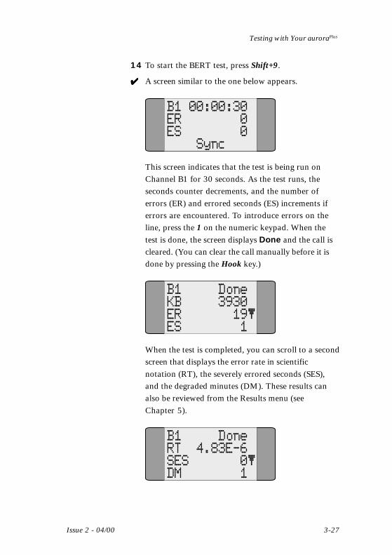
14 To start the BERT test, press Shift+9.
✔✔✔✔✔ A screen similar to the one below appears.
B1 00:00:30ER 0ES 0
Sync
This screen indicates that the test is being run onChannel B1 for 30 seconds. As the test runs, theseconds counter decrements, and the number oferrors (ER) and errored seconds (ES) increments iferrors are encountered. To introduce errors on theline, press the 1 on the numeric keypad. When thetest is done, the screen displays Done and the call iscleared. (You can clear the call manually before it isdone by pressing the Hook key.)
B1 DoneKB 3930ER 19ES 1
When the test is completed, you can scroll to a secondscreen that displays the error rate in scientificnotation (RT), the severely errored seconds (SES),and the degraded minutes (DM). These results canalso be reviewed from the Results menu (seeChapter 5).
B1 DoneRT 4.83E-6SES 0DM 1
chap03.p65 02/05/00, 15:1527

auroraPlus User Guide
3-28 429864
chap03.p65 02/05/00, 15:1528
Issue 2 - 04/00 4-1
Placing and Receiving Calls
4Placing and Receiving Calls
IntroductionThis chapter explains in detail how to place and receivecalls, including how to select the B-channel and the servicetype. It also tells you how to use the speed dial and callwaiting features. All procedures in this section assumethat the tester has been initialized on the interface undertest and is in the IDLE state. If this is not the case, see thesections U-Interface Turn-up and Service Check or Testing the
S-Interface in Chapter 3.
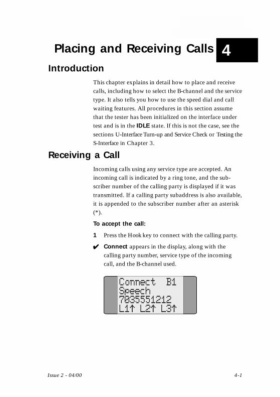
Receiving a CallIncoming calls using any service type are accepted. Anincoming call is indicated by a ring tone, and the sub-scriber number of the calling party is displayed if it wastransmitted. If a calling party subaddress is also available,it is appended to the subscriber number after an asterisk(*).
To accept the call:
1 Press the Hook key to connect with the calling party.
✔✔✔✔✔ Connect appears in the display, along with thecalling party number, service type of the incomingcall, and the B-channel used.
Connect B1Speech7035551212L1 L2 L3
chap04.p65 02/05/00, 15:151

auroraPlus User Guide
4-2 429864
If the auroraPlus does not recognize the service type (andtherefore cannot decode it), it is shown in hexadecimalpreceded by BC (for bearer capability) or LLC (for lowlayer capability). The meaning of these values can befound in the ISDN Q Recommendations.
Setting Up Outgoing CallsThere are several steps involved in setting up an outgoingcall. These are listed below:
• Select the service type for the call• Select the B-channel to use• Dial the number, using speed dial if desired
Selecting the Service Type
Before you can place an outgoing call, you need to selectthe type of service that you want to use for that call. Theservice types available from your auroraPlus are listedbelow:
• Speech ISDN voice (default selection)• 3.1K Aud analog (3.1 kHz) voice• FAX Grp3 Group 3 (analog) facsimile• FAX Grp4 Group 4 (digital) facsimile• Data 64 64 kbps data• Data 56 56 kbps data• Teletex64 64 kbps Teletex
1 From the Main menu, select 1 to access the Callmenu.
✔✔✔✔✔ The Call menu appears, displaying the currentlyconfigured service type and B-channel.
1 DIAL2 SRV:Speech3 CHAN:B10 EXIT
chap04.p65 02/05/00, 15:152

Issue 2 - 04/00 4-3
Placing and Receiving Calls
2 Select 2 to access the Service menu.
✔✔✔✔✔ The first screen of the Service menu appears. (A thirdscreen contains only the 0 Exit option.)
1*SPEECH2 3.1K AUD3 FAX GRP30 FAX GRP4
5 DATA646 DATA567 TELETEX648 X.25
3 Press the number that corresponds to the service thatyou want to use for this call and then press Enter.
NOTE
You do not have to go to the second screen for aselection from that screen to be valid.
✔✔✔✔✔ An asterisk marks your selection in the Service menuand you return to the Call menu. You can now selectyour B-channel.
Selecting the B-Channel
You can select the B-channel on which a voice or data callwill be placed. Your selections are B1 (the firstB-channel), B2 (the second B-channel), or BX (eitherB-channel). By default, the auroraPlus is configured toplace calls on either B-channel (BX).
1 From the Call menu (which displays the currentlyselected B-channel), press 3 to select the B-channel.
✓✓✓✓✓ The Channel Select screen appears. An asterisk marksthe currently selected B-channel.
1*B12 B23 BX0 EXIT
chap04.p65 02/05/00, 15:153

auroraPlus User Guide
4-4 429864
2 Press the key that corresponds to the B-channel thatyou want to use and then press Enter.
✓✓✓✓✓ An asterisk marks your selection in the ChannelSelect menu and you return to the Call menu. Youcan now place your outgoing call.
Dialing the Call
There are several ways to place an outgoing call. You canuse overlap dialing, in which each digit is sent as youenter it; block dialing, in which you enter the entirenumber before you start the call setup; or speed dialing.This section explains overlap dialing and block dialing.The next section explains speed dialing. It is assumed thatyou have already set up and initialized the circuit.
1 From the Call menu, press 1 to access the Dial screen.
✔✔✔✔✔ The Dial screen appears and displays the mostrecently dialed number.
NUM:7035551212
2 • To use overlap dialing, use the Clear key to delete thedisplayed number (if any). Then press the Hook keyfollowed by the digits of your destination number.
✔✔✔✔✔ You see the dial screen and then the numbers as youenter them.
Dial number:7035551212
L1 L2 L3
chap04.p65 02/05/00, 15:154

Issue 2 - 04/00 4-5
Placing and Receiving Calls
• To use block dialing, use the Clear key to delete thedisplayed number (if any). Then enter the digits ofyour destination number followed by the Hook key.
✔✔✔✔✔ The display shows layer status indication while thecall is being established. The screen also shows theservice type being used and the number dialed.
Alerting B1Speech7035551212L1 L2 L3
Connect B1Speech7035551212L1 L2 L3
If the call is unsuccessful, you see a screen like the onebelow. You can scroll to a second screen to see anexplanation of the cause code.
ReleaseCause 16
L1 L2 L3
You can start a BERT test by pressing Shift+9. SeeTesting for Bit Errors in Chapter 3 for more details.
Speed DialingSpeed dialing lets you program up to 10 destinationnumbers, each associated with one of the numbers from0 to 9. When you press Shift plus a number from 0 to 9from the Dial portion of the Call menu, the auroraPlus
retrieves the associated speed dial number for dialing.
To program speed dial numbers:
1 From the Main menu, press 4 to go to the Setupmenu.
chap04.p65 02/05/00, 15:155
auroraPlus User Guide
4-6 429864
✔✔✔✔✔ The first screen of the Setup menu appears.
2 Press 3 to access the Speed Dial screen.
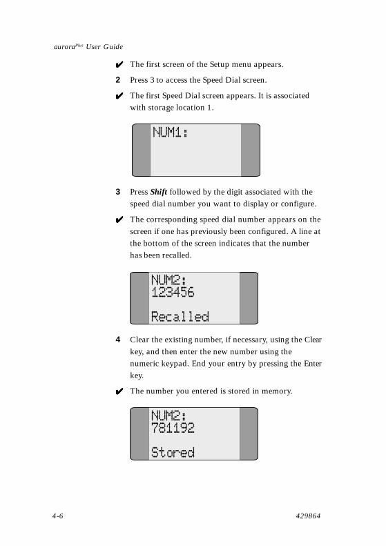
✔✔✔✔✔ The first Speed Dial screen appears. It is associatedwith storage location 1.
NUM1:
3 Press Shift followed by the digit associated with thespeed dial number you want to display or configure.
✔✔✔✔✔ The corresponding speed dial number appears on thescreen if one has previously been configured. A line atthe bottom of the screen indicates that the numberhas been recalled.
NUM2:123456
Recalled
4 Clear the existing number, if necessary, using the Clear
key, and then enter the new number using thenumeric keypad. End your entry by pressing the Enter
key.
✔✔✔✔✔ The number you entered is stored in memory.
NUM2:781192
Stored
chap04.p65 02/05/00, 15:156

Issue 2 - 04/00 4-7
Placing and Receiving Calls
5 Repeat steps 3 and 4 to enter additional numbers.When all numbers have been entered, pressShift+Scroll.
✔✔✔✔✔ You return to the Setup menu.
To use a speed dial number when placing a call
1 At the point in an outgoing call setup where youwould normally enter the destination number (i.e.,when you are at the Dial screen of the Call menu),press Shift+ the digit (0-9) that corresponds to thedirectory number you want to use.
✔✔✔✔✔ The speed dial number is displayed and can be usedto place the call.
Call WaitingThe auroraPlus can indicate that a call is waiting on aB-channel while a first call is already connected on theother B-channel. If a second call comes in while youalready have a call connected on one of the B-Channels, abeep will sound. You can then toggle to the other B-channel and answer the second call.
Use the key combination Shift+4 to toggle between the B-channels, putting the first call in the inactive state whileyou accept the other call or place a second call on theother B-channel. While the two calls are established, youcan use Shift+4 to toggle between the calls.
To disconnect a call, press the Hook key while the call isthe active call. If a second call is established, the unit willdisplay its current status.
Call LoopingYou can loop an active call by pressing Shift+6. PressShift+6 again to unloop the call.
chap04.p65 02/05/00, 15:157

auroraPlus User Guide
4-8 429864
chap04.p65 02/05/00, 15:158

Issue 2 - 04/00 5-1
Additional Functions
Additional Functions
This chapter explains additional tests and capabilities ofthe auroraPlus. These include performing a self-test,displaying block errors, viewing the most recent results,setting up a loop, and reprogramming the tester. It alsoexplains how to adjust the loudspeaker volume.
Self-TestThe auroraPlus self-test tests various functions of thedevice. These tests include a test of the display and anEPROM checksum test. A complete list of tests, with testcodes and possible results, is given on pages 5-3 and 5-4.
It is recommended that you perform the self-test off-lineor on the S-interface with the auroraPlus in the idle state.Calls will not be indicated during the self-test. TheauroraPlus resets itself after the self-test is successfullycompleted.
1 If you are performing the self-test on the S-interfaceand you have not connected to and initialized theS-interface, follow the procedure Testing the
S-Interface in Chapter 3.
2 From the Main menu, press & to access the Setupmenu.
✔✔✔✔✔ The first screen of the Setup menu appears.
1 L2/L32 BERT3 SDIAL4 LOUDSPKR
5 DEFAULTS6 SELFTEST0 EXIT
55555
3 Select ( to run the self-test.
chap05.p65 02/05/00, 15:151

5-2 429864
auroraPlus User Guide
NOTE
You do not have to go to the second screen for 6 tobe a valid selection.
✔ The self-test code entry screen appears.
CODE:Enter a fourdigit securecode
4 To run the self-test, you must enter the authorizationcode, which is $)*+, followed by������#
✔ The Test Selection menu appears.
TEST:
Enter a twodigit code
5 Enter the code of the test that you want to run.Codes can be found in the table on the pages thatfollow.
NOTE
Leading zeros must be entered.
✔ The test is run and the results are printed on thedisplay. For some tests, you may need to pressadditional keys. Refer to the table that follows.
6 To run another test, press Enter to return to the TestSelection menu.
7 To exit the self-test, press Shift+Clear to return to theMain menu.
chap05.p65 02/05/00, 15:152

Issue 2 - 04/00 5-3
Additional Functions
tseTedoC
gninaeM stluseR
10 .yalpsidehtstseT TSETPSID TSETPSID TSETPSID TSETPSID TSETPSID :neht,nosyalpsidllA:1petSlatnozirohllA:2petS
nostnemgeslacitrevllA:3petS
nostnemgeslanogaidllA:4petS
nostnemgesunemllA:5petS
wolfrevodnaswodniwnosyalpsid
20 muskcehcMORPE ,deyalpsidsimuskcehCelpmaxerof FDB6 FDB6 FDB6 FDB6 FDB6
30 tsetdraobyeK:yekrebmunasserP
.deyalpsidsirebmuN
40 tset-fleslanretnI)yllacitamotuasnuR(
sarebmunpetssyalpsiD.nurerastset
syalpsiD KOTSET KOTSET KOTSET KOTSET KOTSET roRRE RRE RRE RRE RRE .tsetfodneta
MARlanretxE:1petSsseccaCCI:2petS
sseccaIFOCRA:3petSsseccaMORPEE:4petS
MORPE:5petSmuskcehc
noitcnufDW:6petS
50 esaelererawtfoSrebmun
sirebmunesaeleRsahcus,deyalpsid 1010101010
T50 T50 T50 T50 T50
60 gnirsuounitnoClangis
GNIRTNOC GNIRTNOC GNIRTNOC GNIRTNOC GNIRTNOC signirdna,deyalpsid
draehsienot
chap05.p65 02/05/00, 15:153

5-4 429864
auroraPlus User Guide
tseTedoC
gninaeM stluseR
70 1BtseTdetcennocarorua1Bgniziestuohtiw
1B>-< 1B>-< 1B>-< 1B>-< 1B>-< deyalpsid
80 2BtseTdetcennocarorua2Bgniziestuohtiw
2B>-< 2B>-< 2B>-< 2B>-< 2B>-< deyalpsid
90 StazHk69 zHk69 zHk69 zHk69 zHk69 zHk69 deyalpsid
71 4poolllatsnI 4POOL 4POOL 4POOL 4POOL 4POOL deyalpsid
81 emulovlamronteS ----GNIR ----GNIR ----GNIR ----GNIR ----GNIR deyalpsid
91 emulovesaercnI +++GNIR +++GNIR +++GNIR +++GNIR +++GNIR deyalpsid
Setting Up a LoopYou can configure the auroraPlus to provide a loop onincoming calls so that it can be used with another testdevice for BERT testing. There are three options tochoose from in the Loop menu:
• AUTO: All incoming calls are answered automati-cally and a loop connected. Use this setting for voiceor data calls when a remote device wishes toperform a looped-back BERT test. An auroraPlus canbe left unattended in this mode.
• MANUAL: Incoming calls are answered manuallyand a loop is connected. Use this setting for voice ordata calls when a remote device wishes to perform alooped-back BERT test.
• OFF: Incoming calls are answered manually andconnected to the microphone and earpiece. Thissetting is usually used for voice calls. Off is thedefault setting.
chap05.p65 02/05/00, 15:154

Issue 2 - 04/00 5-5
Additional Functions
To change the loop selection:
1 From the Main menu, select &�to go to the Setupmenu.
✔✔✔✔✔ The first screen of the Setup menu appears.
1 L2/L32 BERT3 SDIAL4 LOUDSPKR
2 Press � to go to the Layer2/Layer 3 screen.
✔✔✔✔✔ The L2/L3 menu appears and displays the first of twoscreens.
1 PROTOCOL2 SPID3 LOOP4 X.25
0 EXIT
3 Press $ to select Loop.
✔✔✔✔✔ The Loop menu appears.
1 AUTO2 MANUAL3 OFF0 EXIT*
4 Press the key that corresponds to the option youwant to select.
✔ An asterisk indicates your new selection.
1*AUTO2 MANUAL3 OFF0 EXIT
5 If this is the loop mode that you want, press ������to
record your choice and return to the L2/L3menu.
chap05.p65 02/05/00, 15:155

5-6 429864
auroraPlus User Guide
Adjusting the Loudspeaker VolumeYou can adjust the loudspeaker volume to low, medium,or high to suit your preferences.
1 From the Main menu, press & to access the Setupmenu.
✔✔✔✔✔ The first screen of the Setup menu appears.
1 L2/L32 BERT3 SDIAL4 LOUDSPKR
5 DEFAULTS6 SELFTEST0 EXIT
2 Press & to go to the Loudspeaker screen.
✔✔✔✔✔ The Loudspeaker screen appears.
1*LOW2 MEDIUM3 HIGH0 EXIT
3 Select the number that corresponds to the volumeyou prefer.
✔✔✔✔✔ An asterisk marks your selection
1 LOW2*MEDIUM3 HIGH0 EXIT
4 If this is the volume that you want, press ������torecord your choice and return to the L2/L3 menu.
chap05.p65 02/05/00, 15:156
Issue 2 - 04/00 5-7
Additional Functions
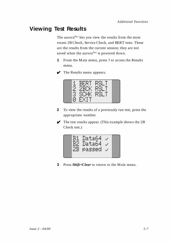
Viewing Test ResultsThe auroraPlus lets you view the results from the mostrecent 2B Check, Service Check, and BERT tests. Theseare the results from the current session; they are notsaved when the auroraPlus is powered down.
1 From the Main menu, press $ to access the Resultsmenu.
✔✔✔✔✔ The Results menu appears.
1 BERT RSLT2 2BCK RSLT3 SCHK RSLT0 EXIT
2 To view the results of a previously run test, press theappropriate number.
✔✔✔✔✔ The test results appear. (This example shows the 2BCheck test.)
B1 Data64B2 Data642B passed
3 Press Shift+Clear to return to the Main menu.
chap05.p65 02/05/00, 15:157
5-8 429864
auroraPlus User Guide
Reprogramming the auroraPlus
The data communications port on the auroraPlus lets youdownload updated code into the flash memory of yourtester. This code is in the form of binary files that can beloaded onto your PC (either from a modem download orfrom diskette) and from there into your auroraPlus.
1 Connect the special cable from your PC to the datacommunications port (DIN port) on the auroraPlus.
2 Power up the auroraPlus.
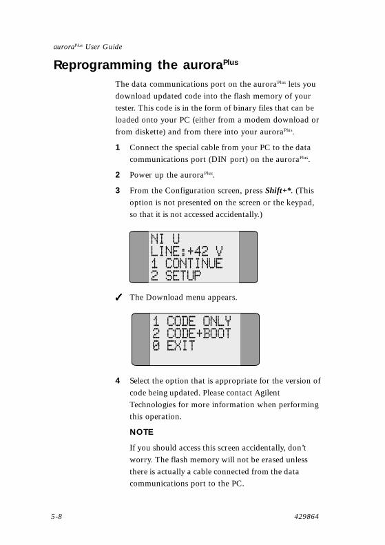
3 From the Configuration screen, press Shift+*. (Thisoption is not presented on the screen or the keypad,so that it is not accessed accidentally.)
NI ULINE:+42 V1 CONTINUE2 SETUP
✓✓✓✓✓ The Download menu appears.
1 CODE ONLY2 CODE+BOOT0 EXIT
4 Select the option that is appropriate for the version ofcode being updated. Please contact AgilentTechnologies for more information when performingthis operation.
NOTE
If you should access this screen accidentally, don’tworry. The flash memory will not be erased unlessthere is actually a cable connected from the datacommunications port to the PC.
chap05.p65 02/05/00, 15:158

Issue 2 - 04/00 5-9
Additional Functions
Returning to Factory DefaultsYou can revert all values to the factory defaults from theSetup menu.
1 From the Main menu, press & to access the Setupmenu.
✔✔✔✔✔ The first screen of the Setup menu appears.
1 L2/L32 BERT3 SDIAL4 LOUDSPKR
5 DEFAULTS6 SELFTEST0 EXIT
2 Press 5 to return all values to factory defaults.
NOTE
You do not have to go to the second screen for 5 tobe a valid choice.
Checking the StatusYou can obtain status information at any time bypressing Shift+#.
If you are using the S interface, a single screen will appear.This screen shows the voltage on the line, the mode of thevoltage (Normal or Restricted), and the status of theauroraPlus battery.
NI SPS2:-6VRestricted
BATT:OK
If you are using the U interface, a total of three statusscreens are available, which you can scroll through as youwould any other screens.
chap05.p65 02/05/00, 15:159

5-10 429864
auroraPlus User Guide
The first screen provides information that is similar to theinformation provided on the S-interface screen, such asthe line voltage and the battery status. It also gives thesealing current (SC).
NI UPS2:-13VSC:NoneBATT:OK
The second screen shows the Near-End Block Errors(NEBE) and the Far-End Block Errors (FEBE). You canclear these counters by pressing the Clear key.
NEBE: 0FEBE: 0
The final screen displays the last received EOC command.
EOC:-Unknown
chap05.p65 02/05/00, 15:1510

Analog Functionality
Issue 2 - 04/00 6-1
66666Analog FunctionalityThe analog line test capability of the auroraPlus is apurchasable option. With this option, you can place andreceive analog calls and monitor activity on the line.
Testing Analog LinesWhen you use the auroraPlus in analog mode, some of thekeys on the keypad have a different meaning than they dowhen you are using the tester in ISDN mode. The analogfunctions are indicated in white on the keypad:
• The Scroll key provides the Redial function.
• The Clear key provides the Flash function.
In addition, the Enter key functions as a Hook key, as itdoes in ISDN mode.
To monitor calls:
1 Set the ISDN/Analog POTS switch on the auroraPlus
to Analog/POTS.
2 Connect your POTS line to the interface connectorusing an RJ-11 connector or alligator clips.
3 Set the Charge/Bat switch to Bat.
✔✔✔✔✔ The Logo screen appears, followed by the Analogscreen.
AGILENTTECHNOLOGIESauroraPlusV1.05 USA
ANALOG MODE1 DIAL2 SETUP3 40KHZ
4 Press the Line Mon switch on the keypad.
✔✔✔✔✔ You can now monitor all transmissions on the line.
chap06.p65 02/05/00, 15:151
6-2 429864
auroraPlus User Guide
To accept an incoming call:
1 When an incoming call is indicated (ring tone isheard), press the ,��-�key.
NOTE
If the auroraPlus was on the Main Analog screen, thefirst press of the Hook key toggles to the Call Statusscreen. You will need to press the Hook key again toanswer the call.
✔✔✔✔✔ Active appears on the display.
2 To terminate the call, press the ,��-�key again.
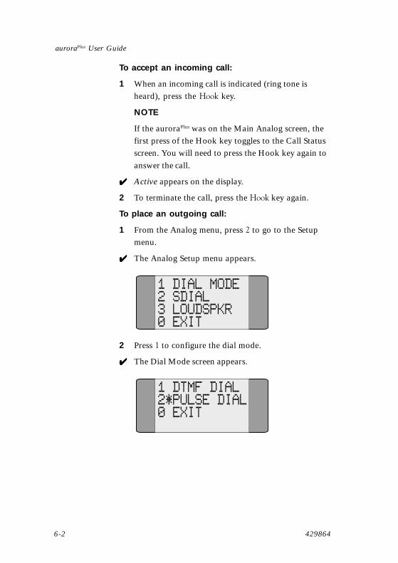
To place an outgoing call:
1 From the Analog menu, press � to go to the Setupmenu.
✔✔✔✔✔ The Analog Setup menu appears.
1 DIAL MODE2 SDIAL3 LOUDSPKR0 EXIT
2 Press � to configure the dial mode.
✔✔✔✔✔ The Dial Mode screen appears.
1 DTMF DIAL2*PULSE DIAL0 EXIT
chap06.p65 02/05/00, 15:152

Analog Functionality
Issue 2 - 04/00 6-3
3 Select the dial mode used on your line:
• DTMF Dial if you are using DTMF dialing
• Pulse Dial if you are using pulse dialing
✔✔✔✔✔ An asterisk indicates your selection.
1*DTMF DIAL2 PULSE DIAL0 EXIT
5 Press �����+������to return to the Main Analogmenu.
✔✔✔✔✔ The Analog menu appears.
ANALOG MODE1 DIAL2 SETUP3 40KHZ
6 Press � to go to the Dial menu.
✔✔✔✔✔ The Dial menu appears.
NUM:
7 Press the ,��-�key to go off hook.
✔✔✔✔✔ You hear the dial tone and Dial num appears on thedisplay.
chap06.p65 02/05/00, 15:153

6-4 429864
auroraPlus User Guide
Dial num
Off Hook
8 Enter the destination number.
NOTE
You can also use speed dial or redial, as explained inthe section that follows, to enter the number.
✔✔✔✔✔ The destination is called, and the number remains onthe display.
NUM:5551212
Off Hook
9 To terminate the call, press the ,��-�key again.
✔✔✔✔✔ The display indicates On Hook.
You can also use block dialing (explained in Chapter 4for ISDN calls) to place an analog call. With block dialing,you enter the destination number before you press theHook key. If you make a mistake while entering thenumber, you can use the Clear key to delete one numberat a time.
To put a call on hold:
If the auroraPlus is connected to an analog PABX with tonedialing and flash signaling, you can put a call on holdwhile you make a second call.
1 With the first call connected, press the ������key.
✔✔✔✔✔ The first call is put on hold, and you hear dial tone.
chap06.p65 02/05/00, 15:154

Analog Functionality
Issue 2 - 04/00 6-5
2 Enter the destination number of the second call.
✔✔✔✔✔ The second call is connected.
3 Press the �������key to disconnect the second call andreturn to the first call.
Using Speed Dial and RedialThe call redial facility automatically redials the mostrecently dialed number. To use the call redial function,simply press the .�!����key once you have accessed theDial screen.
Speed dialing lets you program up to 10 destinationnumbers, each associated with one of the numbers from0 to 9. When you press ������plus a number from 0 to 9from the Dial screen, the auroraPlus dials the associatednumber that you programmed.
To program speed dial numbers:
1 From the Main Analog menu, press � to go to theSetup menu.
✔✔✔✔✔ The Analog Setup menu appears.
1 DIAL MODE2 SDIAL3 LOUDSPKR0 EXIT
2 Press ��to access the Speed Dial screen.
✔✔✔✔✔ The Speed Dial screen appears.
chap06.p65 02/05/00, 15:155
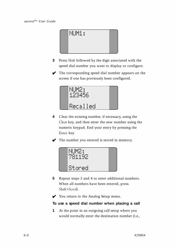
6-6 429864
auroraPlus User Guide
NUM1:
3 Press ������followed by the digit associated with thespeed dial number you want to display or configure.
✔✔✔✔✔ The corresponding speed dial number appears on thescreen if one has previously been configured.
NUM2:123456
Recalled
4 Clear the existing number, if necessary, using the������key, and then enter the new number using thenumeric keypad. End your entry by pressing the������key.
✔✔✔✔✔ The number you entered is stored in memory.
NUM2:781192
Stored
5 Repeat steps 3 and 4 to enter additional numbers.When all numbers have been entered, press�����+������.
✔✔✔✔✔ You return to the Analog Setup menu.
To use a speed dial number when placing a call
1 At the point in an outgoing call setup where youwould normally enter the destination number (i.e.,
chap06.p65 02/05/00, 15:156

Analog Functionality
Issue 2 - 04/00 6-7
when you are at the Dial screen ), press ������+ thedigit (+/0) that corresponds to the directory numberyou want to use.
✔✔✔✔✔ The speed dial number is displayed and the call isconnected normally.
Adjusting the Loudspeaker VolumeYou can adjust the loudspeaker volume to low, medium,or high to suit your preferences.
1 From the Main Analog menu, press � to access theSetup menu.
✔✔✔✔✔ The Analog Setup menu appears.
1 DIAL MODE2 SDIAL3 LOUDSPKR0 EXIT
2 Press $ to go to the Loudspeaker screen.
✔✔✔✔✔ The Loudspeaker screen appears.
1*LOW2 MEDIUM3 HIGH0 EXIT
3 Select the number that corresponds to the volumeyou prefer.
✔✔✔✔✔ An asterisk indicates your selection.
chap06.p65 02/05/00, 15:157

6-8 429864
auroraPlus User Guide
1 LOW2*MEDIUM3 HIGH0 EXIT
4 If this is the volume that you want, press �����+�����to record your choice and return to the Main Analogmenu.
40 kHz TestThe 40 kHz test lets you toggle the 40 kHz tone genera-tor on or off. When the tone generator is turned on, theauroraPlus provides a 40 kHz analog signal. By default thetone generator is turned off.
1 From the Main Analog menu, press 3 to access the40 kHz Test menu.
✔✔✔✔✔ The 40 kHz screen appears.
1 ON2*OFF0 EXIT
2 Press 1 to turn the 40 kHz tone generator on or 2 toturn it off.
✔✔✔✔✔ An asterisk indicates your selection.
1*ON2 OFF0 EXIT
3 Press Shift+Clear to return to the Main Analogmenu.
chap06.p65 02/05/00, 15:158

Appendix A - Menutrees
Issue 2 - 04/00 A-1
AMenutree Diagrams
CALLS
RESULTS
TESTS
SETUP
DIAL
2B CHECK
EXIT
EXIT
SRV
SRV CHECK
CHAN
Main Menu Calls
Tests
EXIT
BERT RSLT
2BCK RSLT
SCHK RSLT
Results
PROTOCOL
X.25
SPID
LOOP
EXIT
L2/L3
L/2 L/3
LOUDSPKR
EXIT
BERT
SELFTEST
SDIAL
DEFAULTS
Setup
�����1/����������2����������������!�3����3��
appendixa.p65 02/05/00, 15:151

auroraPlus User Guide
A-2 429864
�����1/� ��������������
CallsScreen
DialScreen
ServiceMenu
B-ChannelSelect
Select 1 Select 2 Select 3
Speech
Data64
3.1K Aud Fax Grp3
Data56 X25
Fax Grp4
Teletex64
Select 1 Select 2 Select 3 Select 4
Select 5 Select 6 Select 7 Select 8
B1
B2
BX
Select 1
Select 2
Select 3
appendixa.p65 02/05/00, 15:152

Appendix A - Menutrees
Issue 2 - 04/00 A-3
�����1/$�� �����������
�����1/&��.������������
TestsScreen
2BCheck
ServiceCheck
Select 1 Select 2
ResultsScreen
BERTResult
2B CheckResult
ServiceCheckResult
Select 1 Select 2 Select 3
appendixa.p65 02/05/00, 15:153

auroraPlus User Guide
A-4 429864
�����1/)���������������
SetupScreen
L2/L3Screen (seenext page fordetails)
Speed DialScreen
Select 1 Select 2
1 Min
5 Min
30 Secs
Select 3 Select 4
LoudspeakerScreen
BERTScreen
15 Min
Select 1
Select 2
Select 3
Select 4
Low
Medium
High
Select 1
Select 2
Select 3
Self-Test
Secure Code
Test Code
Select 6
Continuous
Custom
Select 5
Select 6
Defaults
Select 5
Set Defaults
Select 1
appendixa.p65 02/05/00, 15:154
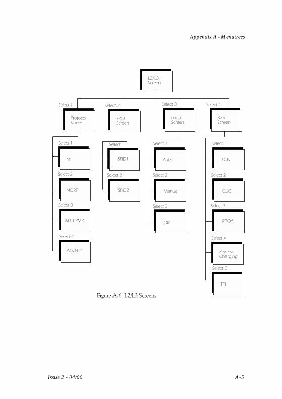
Appendix A - Menutrees
Issue 2 - 04/00 A-5
�����1/(���4�54$��������
L2/L3Screen
ProtocolScreen
Select 1 Select 2
NORT
AT&T-PMP
NI
Select 2
Select 3 Select 4
LoopScreen
X25Screen
SPIDScreen
AT&T-PP
Select 1
Select 2
Select 3
Select 4
Select 1
SPID2
SPID1 Auto
Manual
Off
LCN
CUG
RPOA
Select 1 Select 1
Select 2 Select 2
Select 3 Select 3
ReverseCharging
Select 4
TEI
Select 5
appendixa.p65 02/05/00, 15:155

auroraPlus User Guide
A-6 429864
�����1/*���1������������
Analog
DIAL
SETUP
40KHz
DIAL MODE DTMF
SPEED DIALSPEED DIAL PULSE
LOUDSPKR
Main Menu Setup Dial Mode
appendixa.p65 02/05/00, 15:156

Issue 2 - 04/00 B-1
Appendix B - Technical Specifications
BBBBBTechnical Specifications
U-InterfaceTransmission method 2-wire transmission with echo
compensation
Channel structure 2B+D, synchronization and servicedata
Line code 2B1Q (ANSI T.601)
Transmission rate 80 kBd
Net data rate 144 kbps
Power status bit PS1, PS2 normal (11)
Interface Maintenance Mode Integrated
Supply concept Internal battery
Operating power consumption < 500 mW
S-InterfaceTransmission method Passive 4-wire bus
Channel structure 2B+D, synchronization andmonitoring
Line code AMI (modified)
Total bit rate 192 kbps
Useful bit rate 144 kbps
Range Approx. 150 m (485 ft) for passivebus installation
Supply concept Internal battery
Operating power consumption - 380 mW
appendixb.p65 02/05/00, 15:151

B-2 429864
auroraPlus User Guide
Acoustic DataSending Loudness Rating (SLR) 7 dB ± 3.5 dB
Receiving Loudness Rating (RLR) 3 dB ± 3.5 dB
Sidetone Masking Rating (STMR) 13 to 18 dB
Analog InterfaceDC isolation > 5 Mohms @ 100 VDC
Ring frequency detection 13 to 70 Hz
LD
Make/break period 40/60 ms or 33/66 ms(internal configuration)
Interdigit pause 840 ms
Flash time 300 ms
Access pause 3 seconds
DTMF level -6/-8 dBm
AC impedance 600 ohms or other ACimpedance (internalconfiguration)
DC mask - 400 ohms @ 20 mA
Acoustic DataAcoustic DataAcoustic DataAcoustic DataAcoustic Data
Sending Loudness Rating (SLR) 3 dB ± 3.5 dB
Receiving Loudness Rating (RLR) 9 dB ± 3.5 dB
Ambient TemperatureStorage/Transport -10 ° F to +150° F
(-25° C to +75° C)
Operation +22° F to +126 ° F(-5° C to + 55° C)
appendixb.p65 02/05/00, 15:152

Issue 2 - 04/00 B-3
Appendix B - Technical Specifications
Physical CharacteristicsWeight 1lb 8 oz, including cables
(680 grams)
Length 9.25" (23.7 cm)
Width 2.75" (7.0 cm)
Depth 3.5" (9.0 cm)
appendixb.p65 02/05/00, 15:153

B-4 429864
auroraPlus User Guide
appendixb.p65 02/05/00, 15:164
Glossary
Issue 2 - 04/00 Glossary i
Glossary and Acronyms
Symbols2B+D Two B-channels and one D-channel, an alternate
way of referring to the Basic Rate Interface.
AAddress The digits that identify the origin and/or the
destination of a data communications message.
ARCOFI Audio ring codec filter.
AT&T Custom A custom ISDN protocol used by AT&T.
BB1 The first B-channel on a BRI connection.
B2 The second B-channel on a BRI connection.
Bx A convention to indicate either B-channel (B1 orB2).
B-Channel An ISDN channel that supports data or voicetransmissions at 64 kbps. Also called the bearerchannel.
Basic Rate An ISDN configuration that uses a standard 2-(BRI) wire telephone line to provide two B-channels atInterface 64 kbps and one D-channel at 16 kbps.
Bearer service The types of service (such as voice, data, facsimile,etc.) that the B-channel can carry. Also called bearercapability (BC).
Bit error rate A test that sends a pattern of bits on a data line test(BERT) and then compares the bits received to the bits that
were sent to detect any errors.
glossary.p65 02/05/00, 15:161

Glossary ii 429864
auroraPlus User Guide
Block dialing A dialing method whereby the user enters the entiredestination number and it is sent as a whole in thecall setup.
Bus An electrical path providing a connection for agroup of devices.
CCall screening A facility that identifies the calling party and
displays the calling number to the called party.
Call waiting A telephone service that allows a call to a busytelephone to be held while the busy telephone isnotified that a second call is waiting.
Central office The facility that terminates customers’ telephonelines and provides the switching equipment tointerconnect those lines.
Closed User In an X.25 network, a group of subscribers thatGroup (CUG) are configured such that calls to and from the
group are restricted.
DD-Channel An ISDN channel that supports signaling or packet
data at speeds of 16 kbps (BRI) or 64 kbps (PRI).
DTMF A telephone signaling method in which each key(Dual Tone generates two audio tones.Multifrequency)
EError rate The relationship between the number of incorrectly
received bits or blocks to the total number of bitsor blocks transmitted.
glossary.p65 02/05/00, 15:162

Glossary
Issue 2 - 04/00 Glossary iii
FFar-end block The number of errors detected in transmitted dataerrors (FEBE) blocks at the destination (remote) end.
Flash A momentary interruption in the supervisory signalof a telephone call. A user can obtain this result bypressing the hook key.
HHigher Layer A way of identifying an ISDN service (e.g., speech,Compatibility data, group 4 fax, etc.)(HLC)
Hook A key on the auroraPlus keypad that is used toprovide on-hook (deactivation) and off-hook(activation) functions.
IICC ISDN communications controller.
Integrated A telecommunications network designed toDigital Network transmit and process all types of voice and data(ISDN) traffic using digital transmission and switching.
LLogical Channel A means of identifying the data link that is usedNumber (LCN) across an X.25 network to connect the source and
the destination.
Lower Layer The service provided at the lower layers.Compatibility(LLC)
NNational ISDN A standardized ISDN protocol used in North
America. Also referred to as NI in this manual.
glossary.p65 02/05/00, 15:163

Glossary iv 429864
auroraPlus User Guide
Near-end block The number of errors detected in transmitted dataerrors (NEBE) blocks at the originating end.
Network A piece of equipment that terminates an ISDNTermination connection at the customer premises. The NT1(NT) terminates the physical interface from the central
office at the customer premises. The NT2 is anintelligent device at the customer premises that canprovide functions such as switching andconcentration. The NT1 and NT2 are sometimesphysically combined and called the NT.
Northern A custom ISDN protocol used by NorthernTelecom Telecom. Also called Nortel in this manual.Custom
OOverlap dialing A dialing method in which each digit is sent as the
user enters it.
PPoint-to-point A communications connection mode that provides
a link between one piece of equipment at the sourceand one piece of equipment at the destination.
Point-to- A communications connection mode thatmultipoint provides a link between one piece of equipment at
one end and several pieces or equipment at theother end.
Polarity The positive or negative state of an electricalconnection.
Packet A data transmission method that sends Switchingaddressed packets over physical and logicallinks. The physical link is used only for theamount of time needed to transmit the packet.Also called X.25.
glossary.p65 02/05/00, 15:164

Glossary
Issue 2 - 04/00 Glossary v
POTS (Plain Old Standard analog telephone service.Telephone Service)
Primary Rate An ISDN configuration that provides 23 B-Interface (PRI) channels and one D-channel, all at 64 kbps.
Recognized A transit network over which packet data isPrivate sent. The POA is identified by its assignedOperating DNIC (Data Network IdentificationAgency Code).(RPOA)
Protocol A set of procedures or conventions used tostandardize data transmissions.
Pulse A method of sending dialed digits to thecentral office using an electromagneticmodulation of brief duration.
RR-interface In an ISDN network, the interface between
the TE2 and the TA.
Recommendation The ITU publication that defines the inter-X.25 face between user equipment and a packet
switched network.
Redial A dialing method in which the deviceautomatically redials the last dialed number.
Redirection The sending of a call to an alternatedestination when the intended destination isbusy.
Reverse The placing of a data or voice call such thatcharging the destination is charged for the cost of the
call.
RJ-11 The standard modular jack used with asingle-line telephone.
RJ-45 An 8-pin data modular jack.
glossary.p65 02/05/00, 15:165
Glossary vi 429864
auroraPlus User Guide
SService Profile A record in a data base at the serving central office
that describes the provisioning for an ISDN BRIterminal device. Identified by a Service ProfileIdentifier (SPID).
Service Profile A number, based on your equipment’s directoryIdentifier (SPID) number, that is used to identify the equipment on
the bus.
S-interface The interface between the NT1 and the TA orbetween the NT2 and the TE1.
S/T-interface When the NT1 and the NT2 are physically com-bined, the S and T interfaces are referred to jointlyas the S/T interface.
Sidetone The transmission of undesirable sounds on a localpath from the transmitter to the receiver.
Speed dial The use of a one-digit code to replace a standarddestination address.
Subaddress A two, three, or four-digit field appended to theaddress and used to identify a particular deviceattached to the S-bus in an ISDN BRIconfiguration.
Switch type The make and model of the switch at the centraloffice, usually either AT&T 5ESS or Nortel DMS100.
TT-interface The interface between the NT1 and the NT2.
Teletex One-way data transmission designed for broadcastof graphics and text.
Terminal A device that provides the interface between theadapter (TA) NT1 and the TE2.
glossary.p65 02/05/00, 15:166

Glossary
Issue 2 - 04/00 Glossary vii
Terminal End-user equipment that is part of an ISDNequipment configuration. A TE1 is equipment that is directly(TE) compatible with the ISDN network. A TE2 is
equipment that is not directly compatible with theISDN network.
Turn-up The initialization of an ISDN line.
UU-interface The demarcation point between the customer
premises equipment and the ISDN line from thecentral office.
WWD Watchdog.
XX.25 An internationally recognized standard for
transmitting packet switched data.
glossary.p65 02/05/00, 15:167

Glossary viii 429864
auroraPlus User Guide
glossary.p65 02/05/00, 15:168

Issue 2 - 04/00 Index i
Index
IndexIndexIndexIndexIndex
Symbols
100 Ohm termination 2-32B Check 2-5, 3-212B+D 1-240 kHz test 6-89-12 VDC connector 2-7
A
accepting analog calls 6-2analog line test 6-1Analog POTS switch 2-3asterisk 2-6authorization code 5-2auto loop option 5-4
B
B-channel 1-2, 1-7, 1-9, 4-3B-channel data test 3-21B-channel selection 2-5, 3-9, 4-3B-channel test 3-1B1 4-3B2 4-3Basic Rate Interface
See BRIbattery 2-3, 2-6, 2-7battery charger 2-3battery discharge 2-7bearer capability 4-2BERT 2-5, 3-23, 5-4Bit Error Rate Test
see BERTblock dialing 4-4, 6-4block errors 5-10BRI 1-2Bx 4-3
C
call hold 4-7call waiting 4-7charge LED 2-7
Index.p65 02/05/00, 15:161

auroraPlus User Guide
ii 429864
Charge/Bat switch 2-3Clear key 6-4Closed User Group
see CUGconnectors 2-2CUG 3-17
D
D-channel 1-2, 1-7D-channel packet test 3-14data communications port 2-2data link layer 3-7, 3-8defaults 5-9dialing keys 2-4directory number 1-9display area 2-5downloading code 5-8DTMF dial 6-3
E
earpiece 2-1EOC messages 3-8error rate (RT) 3-27errored seconds (ES) 3-27errors (ER) 3-27
F
factory defaults 5-9flash key 6-1flash memory 5-8flash signaling 6-4
H
hold 6-4Home key 2-5Hook key 6-2
I
ISDN 1-2ISDN/Analog POTS switch 2-3
Index.p65 02/05/00, 15:162

Issue 2 - 04/00 Index iii
Index
K
keyclear 6-4flash 6-1hook 6-2
key combinations 2-4keypad 2-1, 2-2
L
LCN 3-16Line Mon switch 2-3line voltage 2-7Logical Channel Number
see LCNloop 5-4loop function 5-4loopback 2-5, 4-7loudspeaker volume 5-6, 6-7low level capability 4-2
M
manual loop option 5-4microphone 2-1monitor analog calls 6-1
N
Network Terminationsee NT, NT1, NT2
NT 1-3NT1 1-3, 3-12NT2 1-3
O
outgoing call 4-2overlap dialing 4-4
P
PABX 6-4physical layer 3-7, 3-8placing analog calls 6-2point-to-point 3-4PRI 1-2Primary Rate Interface
Index.p65 02/05/00, 15:163

auroraPlus User Guide
iv 429864
See PRIprotocol 1-1, 1-7
AT&T-PMP 3-3AT&T-PP 3-3NI 3-3NORT 3-3
Pulse Dial 6-3
Q
Q Recommendations 4-2
R
R-interface 1-4recharging the battery 2-6Recognized Private Operating Agency
see RPOARedial key 6-1reverse charging 3-18RPOA 3-18
S
S-bus 1-4S-interface 1-4, 1-5, 1-7, 5-1S-interface initialization 3-12S-interface test 3-12S/T-interface 1-4S/U switch 2-4Scroll key 2-4, 2-5sealing current 5-10self-test 5-1service check 2-5, 3-10service profile 1-8, 3-9Service Profile Identifier
see SPIDservice type 3-11, 4-1, 4-2Shift key 2-4speed dialing 4-5, 6-5SPID 1-8, 3-4SPID selection 2-5status 2-5, 5-9switch 2-3
100 Ohm termination 2-3Charge/Bat 2-3ISDN/Analog POTS 2-3S/U 2-4
Index.p65 02/05/00, 15:164

Issue 2 - 04/00 Index v
Index
switch type 1-6
T
T-interface 1-4TA 1-4TE 3-12TE1 1-4TE2 1-4TEI 1-9, 3-16TERM switch 2-3Terminal Adapter
see TAterminal endpoint 1-9Terminal Endpoint Identifier
see TEITerminal Equipment
See TE1, TE2troubleshooting (U-interface) 3-8
U
U-interface 1-4, 1-5U-interface initialization 3-7U-interface turn up 3-1
X
X.25 parameters 3-14
Index.p65 02/05/00, 15:165

auroraPlus User Guide
vi 429864
Index.p65 02/05/00, 15:166