australian environment council - epa.nsw.gov.au · pdf fileaustralian environment council....
TRANSCRIPT

AUSTRALIAN ENVIRONMENT COUNCIL
TECHNICAL BASIS FOR THE REGULATION
OF NOISE LABELLING OF NEW
AIR CONDITIONERS IN AUSTRALIA
JULY 1984

This document ha s been prepared b y t he Env i r o nme n t a l Noise Control Committee (ENCC), wh i ch i s o ne o f a number of specialist committees established t o provide advi c e t o the AEC, through Standing Committee, o n specific areas o f env ironment a l c o ncern .
Thi s document wa s r e l e a s e d b y t he AEC f o l l owi n g its 16t h mee ting i n J u l y 1984.

TECHN I CAL BASI S FOR THE REGULATI ON OF THE NOISE LABELLING
OF NEW AIR CONDI TI ONERS IN AUSTRALIA
1. SCOPE
1 .1 . Thi s document spe c if ie s the t e st pr ocedure s t o be used
in determin ing the noise rating ( ex t e r na l sound powe r
l eve l ) and henc e , label - for each air cond itioner
manufactured o r a ss e.nb led i n , o r impo rted into
Australia.
1 .2. The requirements app l y to al l a i r cond i t i one r s of les s
than l2kW cooling capacity manufactu red on or after
•• . • • • • • • •• and intended or offered fo r s a le i n
Australia.
1 . 3 . The cool ing capac i t y shall be determine d by the me t hod
conta ined in AS1861- 1981. Nomina l t he r ma l cond i t i ons
s ha ll be t hos e i n Tabl e 3 . 1 opera ting condi t i on A o f
t ha t s tanda rd .
2.
2. DEf'lNITIONS
2.1. I n t h is doc ume n t
Abs o rption Coefficient : The ratio wh i ch the s ound
energy a b s o r bed by a su r f ac e o r mater i a l bears t o tha t
incident upon it at a given frequency and under
speci fi ed condit i on s .
Air Conditioner : A split o r packaged mechan ical s ys t em
c apab l e of controll ing a i r t empe r a t ur e a nd
d is t r ibut i on and wh i ch may a l s o contro l the humid i t y
an d c l ean l i ne s s of the a i r to mee t the requirements of
t he c ond i t i on ed s pa ce , bu t excluding eva por a t "ve type
uni ts and hea t i ng onl y units .
Compa r i s on M~ t h o d: That me t hod i n whic h t he sound
power l e ve l is cal cula t ed by c ompa r i ng the measured
s ound pr e ssure l eve l s pr oduc ed by the s our ce i n a
r everbera tion room with the sound pressure l e vel s
produ ced i n the s ame r oom by a ref erence sound s our c e
( RSS ) of known s ound p owe r ou tpu t.
Dire c t Me t hod : That method in whi c h the s ound power
l e vel i s c al c u la t ed f r orn h E' measured s ound pressure
l eve l s prod uc ed by the sour.ce i n a re ve r beration room
an d from l !W vo lu rn e a nd r e ve r be r a t i on t i me o f t he
r oom.
Exte rnal Sound PO\o.'e r Le ve l : The t o ta l s ound e n E' ':" g y
r adi a t ed pe r un i t t I rne ou ts i de t he r oom being hea ted
or cool ed bv t hc a i r c ond i t Lone r ,
F r r> q Uf' ll {"y Il l-1 \~~~ _~·_'" "~! t : T~ p. f ': N .:jl l <;: l C \J o f i n t e r e s t
i llC i ,; :!. c " t lw o c t c v r- 1~ .l;Ir1 S \rJ i t ~1 «(''1 '- :"12 f r o ou o n c t e s
h E' r ,~c r OJ 1 ::' c; ' ! Z .!T1( ! ;:;or)(l ;[ ...

3.
Reverbe r ation Time : The per i od of time re qu ired for
t he mean squa r e sou nd p r e s s ure in the enclosure ,
initially i n a s t e ady state, t o decrea s e , a f t e r t he
s ource i s s t opped , t o one-mill iont h of i t s initia l
va l ue , i .e. by 60 dB. The uni t is the se cond .
Soun d Power Level : Ten t~mes t he loga r i t hm to the base
10 o f t he r a t i o of a given sound power t o t he
reference s o und powe r . The refere nce s ound power is 1
pw. Uni t : decib~l ( dB) .
Sound Pre s s ure Le vel : Ten times the l oga r i thm t o the
base 10 of the ratio of the mean-s quare p r e s s u r e of a
s ound t o t he square of t he referenc e s ound pressur e .
The r efe r ence s ound p r e s s u r e i s 20 p Pa . Uni t :
de cibel (dB).
Tonal Component : Any one - t h i r d octave A - weigh t ed
ba nd wi t h a s ound p t es s u r e leve l t ha t exceeds t he
a r i t hme t i c average o f the t wo ad j acen t one t hird
octave A - we igh t ed band s ound l eve l s by mo re t han
5 dB .
3. NOI SE MEASU REME NT CONDITIONS
3 .1 . Instrumentation
3.1.1. Sound measurin g equ i pme n t s ha l l comp l y with
the arpropriat~ st anda r ds as f o l l ows :
(a) SOL'l1 d l evel meters 0 r si.milar eqllipment
,\ 5 1259 - 19 82 , Sound Le ve l Me t ~ r s Typ e 1 ,
Pr c c is i o r. .

4.
( b) Octave-band pa s s filters or simila r
e qu i pme n t - AS 24 1 , Oc t ave , half Oc t a ve
and One-third Octav~ Band Pass Filters
Intended fo r t he Analys i s of Sound and
Vi bration s .
The ' s l ow' aVErag in g t i me o f the sound l e vel
meter shal l be se lected e xc e p t that l ong e r
averag ing times ma y be used to facilitate time
averag ing o f s ound pres sure level readings .
Wher ~ measurement s ar e made using a
conti nuous ly tra versing microphone , the
averaging time shall no t exceed one t e n t h o f
t he t r a ve rs i ng t i me , e xc ep t t ha t i n t he c a se
of a r oom wh i ch has insignificant spa tial
va r i a nc e a single continuously in tegrating
average may be rak~n over an integral number
of t r a ve r s e pe r i ods.
3.1.2. The a c c ur a c y of the sound measu remen t
e qu i pme n t shall be c he c ke d by me a ns of a
s u i t a b l e a c ou s tic c a l i b r a t or as r e c omme nde d by
the manu f a cture r of the s ound l ev e l mete r or
e qu i va l e nt . Che cks s ha l l be made no t more t h an
30 minu t e s bef0re a nd a f t er a ny meas ur ement is
ma de .
I n t he c ase wher e the s o un d mea s ur i ng
pq u l pme nt r e g is ters a di screpanc y e xcee d i n ~
1 dH be r ve e n tWi co n s e c u t i ve c he c ks , a,,; '
mea s u r erne n t c a r r i e d 0U t i n the 'i n t c r v a l
b e' W ( : (' 11 t ho s e n.J0 .h e c k s sha ll he GPe:pE'd
i n va 1 -: d .

5.
3. 1 . 3. The s ound measuring equipment sha ll have been
calibrated i n a laboratory e quipped fo r the
pu r po s e wi t h i n the two year s prio r to the dat e
of a ny test .
3. 2 . Test Environment
3.2 .1 . Test Area The tests shal l be c onduc t ed in a
r e v e r be r a n t room. ( Exc e p t t e s t s for t ona l
components , ref 5.1.2).
3. 2 . 1 . 1 . Volume o f the Test Room The requ i r ed
minimum volume ba s ed on cons i d e r ation of the
phys i cal size of t h air cond i t i on e r a nd on
t he wave lengths o f the l owe s t fr equen c y ba nd 3be ing measured i s 150 m . I n s ome c a s e s
however, other considerations wi l l determine
the phys i c a l dimensions of the room. In
pa r t i c u l a r , s ee Cl a us e 3 . 2 . 2 . , 3 . 2 .3 .
3.2.1.2. Sha pe of the Test Room The shape shal l be:
( a) Rectangu lar with t he ratio o f any two
dimens ions no t equal t o a n in t ege r, or
( b ) Rec tangular wi th suff icien t d i f f us i n g
e l eme nts i nt roduced , or
( c ) Skew shape with no two s ur f a c e s pa r al l e l
No te : RatI os of 3:2:5 and 1 :2 1/3 : 4 1/3 f or
he i ght , ~li d t h a nd l e ngt h o f a
rectang u l a r ro om have he en f ound () g ive

6.
3.2. 1 . 3 . Abs o r p t i on Coe f fi cien t of t he Test Room
The a vera ge sound absorp tion coeffi c ient of
all surfaces o f t he t e s t room s ha l l no t
exceed 0 .06 over t he fr equency r a nge of
i n t e r e s t , except t hat in the 125 Hz a nd 250
Hz b~nds a maximum 0 .15 is pe r mi s s i b l e .
3.2.2. Air c ond i t i one r Posi ti on Since the air
conditione r under test i s gene rally associa t ed
wi t h t he one r ef l ect ing plane on wh i c h it i s
mounted, i t shall be pl aced i n a co r r e s pon d i ng
posit i on in a s u r f a ce of t he t es t room with
only the x t e r n a l part of the air cond i t ione r
i n the r oom, at least 0.3 m from the centre o f
sai d s u r f a ce , a nd at l e a s t 0 . 8 m away from all
o t he r sur fa ces o f t he t es t r oom. The un i t
shall be mount ed using bra cke ts and othe r
e qu i pme nt r ecomme nded or suppl i ed by t he
manu facturer and shall not be mounted i n such
a way a s to allow s i gn i f i c a n t leakage o f a i r
a r ound t he un i t , or exce s s i ve vib r ati on of t he
uni t du ri ng ope ration . The te st room sha ll be
c l e a r e d of al l ob j ec ts wh i c h may int e r fe r e
wi t h the me a s ur eme nt s .
3. 2 . ] . Mi c r opho ne Po s i ti ons The mic r op hone s v s t ~m
s ha l l cons ist 0 [ :
( a ) an array of ~ r l pa s t six f i xe d mic r ophones
o r si x p r ed e t erm ine d mi cropho ne locat ions
fo r a s i ngl e mova b l e mi~ r ophon c . Pos i t i nns
must be s pacr d no t I ps s t han 1. 5 w fro m
the acoustic c e r r r e pf t he t r-s r u r- i r , no r
l e ss t ha n 1 .L 'Tl fr ..:- n <? a c ;' o t her ;> l' ~ no t:
l e s s Ul a n 0 . 7 rn I r o rn .Jnv r o orn s u r f a c » , 01'.."

7.
(b) a single microphone continuously
trave r s i ng a simi la r space. At least six
measurements s ha l l be made over a path
length of at least 8 m, a nd t he po i n t s
which ma r k t he comme nc eme n t of each
measurement s ha l l be equa l ly spaced a long
the path . The mi c r oph one shall no t pas s
wi t h i n 1 . 5 m of th e acoustic c e n t r e of t he
unit unde r test nor wi t h i n 0 .7 m of any
room sur fac e .
3.2.4 . Ambient Sound The ambient sound pr e s s u r e l e ve l
i n eac h octave band under cons ideration with in
the test r oom s hou ld be at l e a s t 10 dB be low
t he leve l a t t a i n ed
r unn i ng . \{he r e the
t he level with the
s ha ll be co r r e c t e d
ta b le :
Di f f e r e nce be twe e n l eve l s
6
7
8
q
10
whe n t he uni t under t e s t i s
ambient i s within 10 d B of
unit running , the result
ac co r d i ng t o t h e fol .lowinR
Cor r e c t i on to be su b tracted from sound pr e s s u r e level of sourc e
1.3
1.0
0 .8
0.6
0 . 4
; .3 . l)pe r a t i ng Conditions The uni t unde r tes t shall be

8.
3 .3 .1 . The uni t shal l be ope rated cont inuous l y for
l ea s t f i ve minutes be f o r e any sound l e ve l
measurements are made.
a t
3.3. 2 . Whe n the
controls
un it has
shall be
on l y a coo ling cyc le t he
set for maximum cooling.
3.3 .3. When the unit has bot h coo ling and heating
c ycle s , t he co n t r ol s sha l l be set to either
maximum cooling o r maximum heat ing , whiche ver
produces the greater sound power level .
3 .3 . 4 . The compressor and fan es ) s hall be operating
continuousl y during t he test a nd fans s ha l l be
ope r a t ed a t t he h i ghe s t available s pe ed
setting . ( If necessa ry. the thermostat ic c ut
out on t he comp r e s s o r ma y be by-pas sed o r made
ina c t i. ve in o r der 0 en sure cont inuou s
compressor ope r a ti on . )
3. 3.5. Ai r ve n t s on the unit shall
sound level measurements .
be c losed du r i ng
3.3 .6 . No ice shall be vi s i b l e
unit during s ound l e vel
on any part o f
measurements .
t he
3 . 3 . 7 . If the un i t
f i l l e d .
has a water t r ough it s ha l l he
(~ . t"OISE LEV!'.!.. DETERt-lINATJ Ot,
4.1. Tv s t. s sh ;1I 1 be c ondu c t.ed to determine he e x t e r nal
~OUT'd pressure l e ve l s and ho nc e sound p o-...er le vels in
.a c b 0 " ,1 \" 0 b.s u d in r h c f r c q uc n c v r a n g (-' o f i n t e r e s t .
Ei t h t>. r rh c c'l i !- (' C't" ''''Fr h oc :'r ":0 f'; f' :t :- t S 0 n " " , r- h o d o f
r c s r i m: ~ ~ 3 1 1 ~)(' u s e d .

9 .
4 . 2 . Direct Method
4. 2.1. Wh en measu ring the reve r beration time o f the
r oom, a sufficient number of decays sha l l be
mea su r ed to ensure reliability of
reverbe r ation time T.
4. 2.2 . I n t he ca se o f fixed mi c r ophone positions
( i nc lud i ng a traversing microphone whic h
halts ) the time-averaged sound pressure level
at each position shall be measured over a
per iod o f at least 30 s f or the 125 Hz band
and 10 5 fo r the othe r bands. In the case of a
co nt i nuous l y t r av e rs i ng microphone the
measurement s s ha l l commence a s the microphone
pas se s eac h of the severa l prede termined
po s i t i ons on i t s path, excep t as provided for
in 3 . 1. 1.
4 . 2 . 3 . Computation o f Mean Sound Pr es s u r e Leve l (L )p
If t he r ange of t he value s ( L ) of t he sound i
pressure levels is less than 6 dB the test
room ma y be a s sume d t o be su i t a bl e for
measuring the sound powe r of t he unit
concerned. Al s o a simple arithmetic average
may be t ake n , that is:
T 1~. ;-; L r..
l' ,\ ]
H the ril nge of v?llJe~ is 6 d B to 10 dB
inc I u ". I ..' ~ , t hp. mea n s ound pr e s SlI r e l e v e l L p

10.
If t he range exceeds 10 dB, the sound fiel d
devi ates too fa r from uniformit y t o be us e d
f o r accurate measurement of soun d power, an d
t he tes t room is uns ui table for the un it unde r
t e s t.
4.2.4. Computation o f Sound Power Le vel(~)
The sound powe r level can then be calculated
as fol l ows :
t Lp - 10 loglO To
+ 10 loglO ~o + 10 log iO ( 1 + ~~)- 1 4
I n t h is f o rmul a
L is the sound powe r level o f the machineW
under t e s t r e 1 pW
Pm Lp 20 log th ~ mean sound pr e s s ur e
10 Po
level o f th e machine under test wi t h respect
to Po = 20 }JPa
T revrrberntion t j m~ in second s of t he test
rO i'lTJ

11.
3v vo lume o f the room i n m
Va
2S = su r face a rea o f r oom sur f a ce s i n m
~ wa ve l e ng t h o f so und a t centre fre quenc y
o f oc t av e band, i n m.
4 . 3 . Compari son Me t hod
4 .3 .1 . The mean sound pressure l ev el in each ba nd
shal l be determined f or bo t h t h e unit under
t e s t and a r e f ere nc e s ound s ou rce o f known
sound powe r Wr by followi ng the p rocedu re of
4. 2 . 1 and 4 . 2 . 2 .
The Re f e r e nce Sound Sour c e shall be po s i t i oned
as c l os e l y a ~ poss ibl e to ( bu t not wi t h in .8 m
o f) the uni t be i ng tested .
4 . 3 . 2 . The sound power l eve l is t he n c a l c u l a t ed a s
follows :
L L + L L w P w r pr
where
L is the so und powe r l eve l o f the un it under w
t es t r e 1 p W.
') 1 Pm the me an sound pr e s s ur e [,p - ,-0 a g I O Po '
l e v e l \·! i t ~ r e s p e c t t o Po -= 20 /J1'3 .

12.
WrL 10 log lO Wo ' t he sound power l e vel of
wr the r e f e r e nce source wit h re spect to Wo = 1 pW.
PrnrLpr 20 log --- the mean sound pre ssure10 Po •
l e ve l o f t he r e f e r ence source with
re spect t o Po = 20 p Pa .
5. DETERMINATION OF SOUND POWER LEVEL
5.1 .1 The A-wei ghted sound powe r level L in de c i be l s reWA 1 pW of the unit shal l be cal culated as f o l low s :
7 0 . 1 (Wj + Bj) L 10 log L 10
WA 10 j =1
Wj is the sound powe r level in the oc t ave ba nd wi th
c e n t r e f r eque nc y f . Hz , and t he va l ue s o f Bj a r e as J
tabu lated
j f . Bj J
1 125 - 16 . 1
2 250 - 8 . 6
3 500 - 3.2
4 1000 a 'S 2000 + 1.2
(, 4000 -. 1.0
7 8000 - 1.1

13 .
5 . 1. 2 (a)The L sha l l be a d j us t ed by +5 dB(A) whe n t he noiseWA o f t he un i t unde r t e s t ha s one o r more tona l
c omponen t s .
Tona l compon en t s may be ve r i f i ed by f r ee field testing
of the un i t wi t h 1 / 3 octave ba nd ana l ys i s .
5. 1 .2(b) The r e su l t i ng ~A shall be ad justed to a whole
numbe r as f o l lows:
f r ac t i on roundi ng
< 0.5 down to who l e number
~ 0.5 up to who l e number
5.2 Wh e r e .me asurement s have be en made on both c ool i ng and
heating cyc l es , t he h i ghe r of t he t wo A-weighted sound
power levels shal l be used for the purposes o f the
label .
5 . 3 The Outside Soun d Power Lev e l sha ll be t he A-weighted
sound powe r level ~A adjusted in accordance with the
requ irements of part s 5 . 1.2(a ), 5 . 1 . 2 ( b ) an d 5 . 2 of
this Technical Basis .
6 . LABEL FORMAT
6. 1 . The Sound Power Level o f a unit shal l be displayed on
a l abe l wi t h dimensions 6 cm x 10 em. The Sound Powe r
Le ve l numbe r shall ~c displa ye d i n figures at l e ns t
1 em h ~gh .
6.2. The l abe l sh al l ~a v ~ a permanen t c l~arly v i sihl e h l a~ k
14.
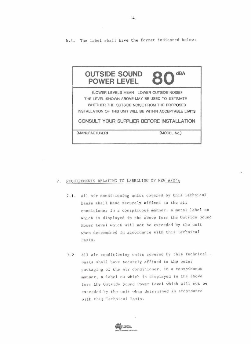
6. 3. The label s ha ll hav e the forma t ind icat ed below:
OUTSIDE SOUND 80 dBA
POWER LEVEL
(LOWER LEVELS MEAN LOWER OUTSIDE NOISE)
THE LEVEL SHOWN ABOVE MAY BE USED TO ESTIMATE
WHETHER THE OUTSIDE NOISE FROM THE PROPOSED
INSTALLA TION OF THIS UNIT WILL BE WITHIN ACCEPTABLE LIMITS
CONSULT YOUR SUPPLIER BEFORE INSTALLAnON
(MANUFACTURER) (MODEL No.)
7. REQUI REMENTS RELATI NG TO LABELLING OF NEW A/CIs
7.1. All air cond i t i on i ng un its covered by t h i s Tec hn i c a l
Ba s is shall have s ec u r e l y a f fixed t o t he a i r
con di t ioner i n a con sp icuou s ma nne r , a me t a l l a bel on
whi ch i s dis playe d in t he ab ove form the Outside Sound
Power Leve l wh i c h wi l l not be exce ede d by the uni t
when determ ine d i n accordance wi th t h is Te chni ca l
Basis.
7. 2 . All air c ond i t i on i ng units covered hy th i s Te chn i c a l
Basi s s ha ll ha ve s ec u r e l y a f f i xed t t he ou t e r
packag ing o f t he a i r c o nd t t i oue r , in a co ns p t cuous
manner , a label on wh i c h i s displayed in the abo ve
f o r m t he Outsidp Sound Power Le e l wh i c h wil l na t b ~
exceeded by t he I)ni r whe n de t e rm i ne i n accordance
wi t h this T e c h~ i c al Bns is _
O "I',~~"'·