australian standard 4032.1 wa termark lic no. 20137 ... · installation, commissioning and...
TRANSCRIPT

15mm & 20mm THERMOSTATIC MIXING VALVE
FOR USE IN AUSTRALIA
INSTALLATION, COMMISSIONINGAND MAINTENANCE INSTRUCTIONS
DR DR
AustralianStandard
4032.1Lic No. 20137
15mm & 20mmTHERMOSTATIC MIXING VALVE
FOR USE IN AUSTRALIA
INSTALLATION, COMMISSIONINGAND MAINTENANCE INSTRUCTIONS
TM
WaterMarkATS S5200.012LIC NO.20042
TM
WaterMark
TM
WaterMark
TM
WaterMarkATS S5200.012LIC NO.20042

CONTENTS
PAGE
1. INTRODUCTION ..............................................................2
2. WARRANTY........................................................................3
3. PRODUCT RANGE & PHYSICAL DESCRIPTION....................4
4. RECOMMENDED PRESSURES AND TEMPERATURES ............6
5. FLOW SIZING GRAPH........................................................7
6. INSTALLATION ..................................................................8
7. COMMISSIONING OF THE VALVE....................................12
8. SHUT DOWN TEST ..........................................................15
9. MAINTENANCE AND SERVICING ....................................16
10. FAULT FINDING ..............................................................18
11. COMMISSIONING REPORT ............................................20

1
FOR SALES & TECHNICAL SERVICE
Ph. 08 9277 5514 Fax. 08 9277 9418
Australian Valve Group (AVG) reserves the right to change anyproduct specification or information contained in this publication, atany time and without notice. Every care has been taken to ensureaccuracy in the preparation of this publication which has been issuedfor guidance only. No liability can be accepted for any consequenceswhich may arise as a result of its application.
AVG is a Trade mark of The Australian Valve Group Pty Ltd ABN: 89 068 227 270
2
1. INTRODUCTION:
The AVG Thermostatic Mixing Valve is a high performanceThermostatic Mixing Valve suitable for a wide range of applications.The valve is designed to comply with Australian Standard AS4032.1for Thermostatic Mixing Valves-Materials, Design and PerformanceRequirements and the NSW Health Department requirements. Themixing valve has the following features:
(a) Meets the requirements of AS4032.1Thermostatic Mixing Valves,
(b) Provides high stability of mixed water temperature even underchanging inlet conditions,
(c) Ensures rapid shut down of mixed outlet flow in the event of hot, or cold water supply isolation,
(d) Easily serviced on site(e) Suitable for installation into AS3500 compliant systems with hot
water temperature as low as 60°C,(f) The adjustment mechanism can be locked to prevent tampering
WARNINGCare needs to be taken when installing this valve, as the valve, pipework and adjacent areas may be hot and could cause a burn injury.
The AVG Thermostat mixing valve is not to be considered as analternative to adequate supervision and duty of care during its useand operation.

3
2. WARRANTY:
AVG warrant their valves against manufacturing defects for two (2)years subject to the following conditions:
1) In accordance with the National Plumbing and Drainage CodeAS3500 and all relevant Statutory and Local Codes in the Stateor Territory in which the valve is installed by a licenced plumber.
2) The valve must be installed in accordance with the AVGinstallation instructions supplied with the valve.
3) The AVG warranty covers replacement of the valve only, at nocharge. Costs to return the valve to AVG and replace the oldvalve are at the purchaser’s expense.
4) The valve must be returned to AVG with a completed “AVGWARRANTY CLAIM FORM”.
5) Where the valve forms part of a hot water system, the valvemust be installed according to the hot water systemmanufacturers’ specifications, in addition to all Statutory andLocal State or Territory requirements.
6) The warranty is void if:• The valve has been damaged in any way.• The valve has been tampered with.• Incorrect installation.• The failure of valve is due to faulty manufacture/installation
of the hot water system of which the valve forms a part.• The valve has failed due to excessive pressure or temperature
outside the valve specification.

4
• The valve has failed due to non-compliance with thePlumbing Code AS3500.
• The valve has failed due to foreign matter or scale build upinside the valve.
7) The AVG warranty does not cover any claims for damage towalls, carpets, furniture, foundations or any other consequentialloss, directly or indirectly as a result of leakage from the valve,subject to any Statutory Provisions to the contrary.
AVG RESERVES THE RIGHT to change its specifications withoutprior notice and will not accept liability for any claim arising fromsuch change.
3. PRODUCT RANGE & PHYSICAL DESCRIPTION:
The AVG Thermostatic Mixing Valve is available complete with inletservice fittings. The inlet to the fittings is 1/2” BSP male, and theoutlet from the valve is 1/2” BSP male adapter with an optional 3/4”BSP male adaptor. The service fittings consist of isolating ballvalves, strainers, pressure test points and non-return valves. Thestrainers can be serviced and cleaned without disturbing theinstallation (refer to Section 9). The inlet service fittings alsoincorporate union type fittings enabling the thermostatic mixingvalve to be removed from its installation without disturbing itspipework.
The schematics and dimensions of the valve are shown opposite(Fig. 1)
The AVG Thermostatic Mixing Valve is available complete with inlet service fittings. The valve is available with 15mm (½”) or 20mm (¾”) inlet connections x 20mm (¾”) compression with optional 15mm (½”) adaptor. The service fittings consist of isolating ballvalves, strainers, pressure test points and non-return valves. Thestrainers can be serviced and cleaned without disturbing theinstallation (refer to Section 9). The inlet service fittings alsoincorporate union type fittings enabling the thermostatic mixingvalve to be removed from its installation without disturbing itspipework. The schematics and dimensions of the valve are shown opposite (Fig. 1)

5
Valve Dimensions (Fig. 1)
DR DR
153
222
6060
54237.5
153.5
56.8 54.5
45.9
Valve Dimensions (Fig. 1)
6
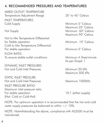
4. RECOMMENDED PRESSURES AND TEMPERATURES
MIXED OUTLET TEMPERATURETemperature Adjustment Range 35° to 45° Celsius
INLET TEMPERATURESCold Supply Minimum 5° Celsius
Maximum 25° CelsiusHot Supply Minimum 60° Celsius
Maximum 90° CelsiusHot to Mix Temperature Differential for Stable operation Minimum 10° CelsiusCold to Mix Temperature DifferentialFor stable operation Minimum 5° Celsius
FLOW RATESTo ensure stable outlet conditions Minimum 4 litres/minute
As per Graph 1
DYNAMIC INLET PRESSURESHot and Cold Inlet Pressures Minimum 20 kPa
Maximum 500 kPa
STATIC INLET PRESSUREHot and Cold Inlet Pressures Maximum 1000kPa
INLET PRESSURE RATIOMaximum inlet pressure ratioFor stable operation 10:1 (either supply)(Hot: Cold or Cold:Hot)
NOTE: For optimum operation it is recommended that the hot and coldwater supply pressures be balanced to within +/- 10%.
NOTE: Notwithstanding the above, compliance with AS3500 must bemaintained.

7
5. FLOW SIZING GRAPH
The AVG Thermostatic Mixing Valve is suitable for many applications. TheHeadloss Characteristic for Mixed Outlet Flowrate verses Balanced InletPressure is shown below in Graph 1. It is important that the valve is sizedcorrectly.
Note: To ensure optimum performance the minimum outlet flow of themixing valve during operation should be at least 4 litres/minute.
It is important that the valve and pipe work is sized such that they complywith those listed in AS3500.1.2. and -Appendix B to ensure the watervelocity in the pipework is within the allowed limit.
If the valve is to be installed and operated under unequal inlet pressuresthe lower inlet pressure determines the outlet flow rate. However, foroptimum performance and stability it is recommended that the valve beinstalled with balanced dynamic inlet pressures (+/- 10%).
Graph 1
8
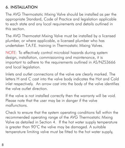
6. INSTALLATION
The AVG Thermostatic Mixing Valve should be installed as per theappropriate Standard, Code of Practice and legislation applicableto each state and any local requirements and details outlined inthis section.
The AVG Thermostat Mixing Valve must be installed by a licensedplumber, or where applicable, a licensed plumber who hasundertaken T.A.F.E. training in Thermostatic Mixing Valves.
NOTE: To effectively control microbial hazards during systemdesign, installation, commissioning and maintenance, it isimportant to adhere to the requirements outlined in AS/NZS3666and local legislation.
Inlets and outlet connections of the valve are clearly marked. Theletters H and C cast into the valve body indicates the Hot and Coldinlet respectively. An arrow cast into the body of the valve identifiesthe valve outlet direction.
If the valve is not installed correctly then the warranty will be void.Please note that the user may be in danger if the valvemalfunctions.
Check to ensure that the system operating conditions fall within therecommended operating range of the AVG Thermostatic MixingValve as detailed in Section 4. If the hot water supply temperatureis greater than 90°C the valve may be damaged. A suitabletemperature limiting valve must be fitted to the hot water supply,

9
prior to the inlet fittings, if the temperature of the hot water will riseabove 90°C. It is also important that both of the inlet dynamicsupply pressures are 500kPa or less. If either supply pressureexceeds 500kPa then a suitable pressure reducing valve must befitted prior to the inlet control valve to reduce the pressure to anacceptable limit.In order to achieve optimum performance from thevalve it is recommended that the inlet pressures are balanced towithin 10% of each other.
The water quality conditions should comply and not exceed thelimits as listed in AS3500.4, Section 3.7.1.
It may be necessary to install a water softener or water treatmentdevice.
NOTE: In some installations, flick mixers and solenoid valves areused. The water pressure may be seen to spike outside thatrecommended for the valve, during rapid shut off conditions. Evenif the spike only lasts for a split second it is still considered to beoutside the operating conditions and may cause the valve tooperate incorrectly.
If this does occur, then measures must be taken to control thespike, such as inline pressure reducing valves directly before thevalve inlets.
Thoroughly flush the pipe work with clean water to removeany swarf or debris before the valve is installed.
Care should be taken to prevent water damage occurringduring this procedure.

10
It is required by AS3500.4.2 that “Each thermostatic mixing valveshall have an isolating stop tap/valve, line strainer and non-returnvalve fitted to the hot and cold water supply lines”. The inlet fittingssupplied with each TMV will ensure this requirement is met. If theAVG Thermostatic Mixing Valve is installed without the supplied inletcontrol valves then it will be necessary to install a separate isolatingvalve for ease of servicing, a non-return valve to prevent cross –connection and a strainer to both inlets to the valve.
Ensure that the test plugs in the top of the inlet fittings are water tight.
Install the valve so that it can be accessed easily for maintenanceor servicing. The valve can be installed in a wall cavity, under abasin or on a wall, however it is essential that the mixing valve andinlet fittings are easily accessible for servicing.
During installation or servicing heat must not be appliednear the mixing valve or inlet fittings, as this will damage thevalve and inlet fitting internals.
Note: The AVG Thermostatic Mixing Valve is intended mainlyfor use in applications with set temperatures of 45°C. orbelow. When installed at higher set temperature, the performancemay be less than specified in AS4032.1.
If the set temperature required is higher, then an AVG TemperingValve approved to AS4032.2 would provide a greater margin forsafety in reducing scalding accidents.

11
CO
LD S
UPP
LYH
OT
SUPP
LY
MIX
ED O
UTL
ET
A B
PIPE
WO
RK
PRES
SURE
LIM
ITIN
G V
ALV
E (IF
REQ
UIR
ED)
ISO
LATI
NG
VA
LVE
C
CO
LD W
ATER
TES
T PO
INT
E
LIN
E ST
RAIN
ERD
RIG
HT
AN
GLE
BA
LL V
ALV
E A
SSEM
BLY
TEM
PERA
TURE
LIM
ITIN
G V
ALE
(IF
REQ
UIR
ED)
JH
THER
MO
STA
IC M
IXIN
G V
ALV
E
NO
N R
ETU
RN V
ALV
E
GF
AB
CD
EF
GF
ED
CB
H
JJ
Schematic Installation Diagram (Fig. 2)

7. COMMISSIONING OF THE VALVE
Upon completion of the installation, the valve should be tested andcommissioned as per the procedure outlined below or as specifiedby the local authority. The entire procedure should be read throughthoroughly prior to the commissioning of the valve. A calibrateddigital thermometer having rapid response time with maximumtemperature hold, a small flat bladed screw driver, an 8” shiftingspanner and the TMV protective cap will be required to check andset the outlet mixed temperature of the valve.
• Ensure all outlets that will be serviced by the valve have adequatewarning signs posted to ensure that no outlet is used duringcommissioning.
• Open the cold supply line to the valve, then open the hot supplyline, ensuring there are no leaks.
• Open the outlet that is closest to the mixing valve.
• Allow the mixed outlet to flow for at least 60 seconds to allow thetemperature to stabilize before taking a temperature reading at theoutlet with a digital thermometer. The flow rate should be at least4L/min. The flow rate can be checked with the aid of a known sizecontainer and a stopwatch. The temperature should be taken atthe closest outlet served by the thermostatic mixing valve.
• If the outlet temperature needs adjustment then the followingssteps are required:
12
13
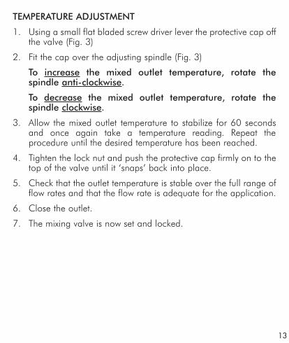
TEMPERATURE ADJUSTMENT
1. Using a small flat bladed screw driver lever the protective cap offthe valve (Fig. 3)
2. Fit the cap over the adjusting spindle (Fig. 3)
To increase the mixed outlet temperature, rotate thespindle anti-clockwise.
To decrease the mixed outlet temperature, rotate thespindle clockwise.
3. Allow the mixed outlet temperature to stabilize for 60 secondsand once again take a temperature reading. Repeat theprocedure until the desired temperature has been reached.
4. Tighten the lock nut and push the protective cap firmly on to thetop of the valve until it ‘snaps’ back into place.
5. Check that the outlet temperature is stable over the full range offlow rates and that the flow rate is adequate for the application.
6. Close the outlet.
7. The mixing valve is now set and locked.
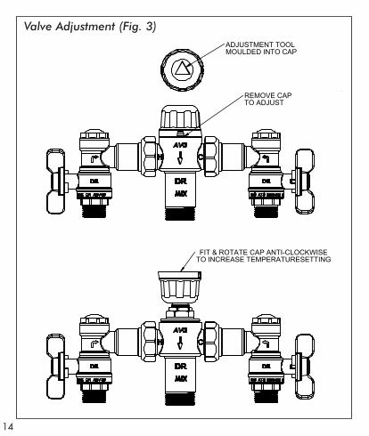
Valve Adjustment (Fig. 3)
14
ADJUSTMENT TOOLMOULDED INTO CAP
REMOVE CAPTO ADJUST
FIT & ROTATE CAP ANTI-CLOCKWISETO INCREASE TEMPERATURESETTING
Valve Adjustment (Fig. 3)

8. SHUT DOWN TEST
Now that the mixing valve has been set and locked it is necessary toperform a shut down check. Allow the mixed water temperature tostabilize and note the outlet temperature. While holding a digitalthermometer in the outlet flow, quickly isolate the cold water supply tothe valve. The outlet flow should quickly cease flowing. As a rule ofthumb the flow should be less than 0.1L/min following the isolation.Monitor the maximum outlet flow temperature, and record this on theCommissioning Report at the back of this instruction booklet. Thetemperature should not exceed that allowed by the applicablestandard or code of practice for each state. Restore the cold watersupply to the valve. After the mixed water temperature has stabilizednote the outlet temperature ensuring the outlet temperature has reestablished.
Now repeat the above test, except this time quickly isolate the hot watersupply to the valve. The outlet flow should quickly slow to a trickle. Asa rule of thumb the trickle should typically be less than0.4L/min@500kPa down to less than 0.1L/min@100kPa followingthe isolation. Restore the hot water supply to the valve and measureand record the outlet temperature after the mixed water temperaturehas stabilized ensuring the outlet temperature has re established.
Ensure that all details of the Commissioning Report are completed andsigned by the relevant signatories. A copy of this report should be keptwith the installer and owner of the premises.
The valve is now commissioned and it can be used within the technicallimits of operation.
15

9. MAINTENANCE AND SERVICING
The AVG Thermostatic Mixing Valve should be serviced andcommissioned on an annual basis, unless the installed conditionsrequire more attention.
ANNUAL MAINTENANCE PROCEDURE
Every 12 months the AVG Thermostat Mixing Valve should be inspectedand tested. The valve should be cleaned and inspected for leaks.
Isolate the hot and cold supplies to the mixing valve by closing the inletball valves. Remove the inlet fitting filter cover with a suitable spannerand then remove the mesh strainer, as shown in Fig. 4 below. Thestrainers should be cleaned with a dilute water solution of suitabledescaling solvent (such as CLR), checked for damage and thenthoroughly rinsed with clean water. The strainers can then be re-fittedinto the valve, and the top cover replaced and tightened to a maximumtorque of 15Nm into the inlet valve bodies.
If the valve fails to shut down or fails to maintain its set temperaturethen refer to the fault findings solutions outlined in section 10. Thevalve piston ‘O’ ring and thermostatic element/shuttle assembly mustbe replaced every 5 years.
Check that the valve and the top of the inlet fittings are tight and thatthere are no leaks. The valve must then be recommissioned as perSection 7, including temperature adjustment and shut down testing.
16
or sooner when required.

17
Servicing Diagram (Fig. 4)Servicing Diagram (Fig. 4)
SHUTTLE &0282 ELEMENT
3
2
1
4
5
MESHSTRAINER
BALL VALVE SHUT BOTH SIDES
FLOW GUIDE
ITEM DESCRIPTION1 TOP O-RING2 ADJUST O-RING3 BODY O-RING4 PLUG O-RING5 CAP O-RING

10. FAULT FINDINGFAULT/SYMPTON CAUSE RECTIFICATION
1.1.The desired mixed Hot & cold supplies Refit the valve with water temperature cannot are fitted to the wrong Hot/Cold supplies fittedbe obtained or valve is connections. to the correctdifficult to set. connections.
Valve contains debris. Clean valve ensuringdebris is removed &components are notdamaged.
Strainers contain Clean strainers debris. ensuring debris is
removed.Non-return devices are Check non-returndamaged. device is not jammed.
Clean if necessary.2. The valve will not The hot to mix Raise hot water
shut down. temperature differential temperature.is not high enough. Replace shuttle ’O’ ringSealing seat is Clean seat usingDamaged or fouled by suitable descalingdebris. solution.
Replace element assembly.3. Mix temperature Debris is fouling valve. Clean the valve
ensuring that all debrisis removed and components are notdamaged.
Flow rate below Rectify any pressure4L/min. deterioration.Strainers are fouled. Clean strainers.Systems may be Check system pressure,Fluctuating outside install pressure controlValve parameters valves to ensure inlet
conditions are withinthose stated in 4.
4.Mix temperature Inlet conditions Install suitable pressurechanging over time (pressures or temperatures) control valves to ensure
are fluctuating. Inlet conditions are withinthose stated in Sect 4.
18

FAULT/SYMPTON CAUSE RECTIFICATIONStrainers contain Debris. Clean strainers ensuring
Debris is removed.5. Either full hot or cold Valve is incorrectly set Adjust mix temperatureflowing from outlet fixture between 35-45°C as required.
Hot/Cold water has Replace faulty non-returnmigrated to other inlet. valves.
6. No flow from the valve Hot or cold water failure. Valve functioningcorrectly. Restore inletsupplies and check mixtemperature.
Strainers are fouled. Clean strainers.7. Flow rate reduced or Valve or inlet fittings Check valve & inletfluctuating fouled by debris. fittings for blockages.
Dynamic inlet Ensure the dynamic inletPressures are not within pressures are nominallyThose recommended limits. Balanced to within +/- 10%.
8. Mixed water Valve has been tampered Readjust valve to required temperature too hot or cold. with. set temperature.
Valve incorrectly set. Readjust valve to requiredset temperature.
Inlet temperatures are not Ensure inlet temperaturesWithin specified limits are within the specified
Limits as listed in Sect 4.9. Warm water Adjuster at maximum mix Mixed water is at temperature adjuster temperature stop. Maximum temperature.difficult to move. No higher mix
temperature adjustmentis available
Valve shuttle into Wind adjuster out untiloverstroke set temperature required
is achieved.10. Hot water flows into Non return valves faulty Replace themthe cold water system orvice versa.11. Valve is noisy Water velocity above Reduce water velocity
velocity requirementsof AS3500.1.2.
19

AUSTRALIAN VALVE GROUP (AVG)COMMISSIONING REPORT FOR THERMOSTATIC MIXING VALVES
(use a separate sheet for each valve)Name of Establishment: ........................................................................Address of Establishment:......................................................................Phone Number:....................................................................................Contact Person: ..............................................Date: ............................Work Order No: ..................................................................................Make & Model of Hot Water Unit: ........................................................Temp of Hot Water: ..........................................................................°CHot Water Pressure kPa: ........................................................................Cold Water Supply via: ........................................................................Pressure Reducing Valve Fitted: Yes / NoTemp of Cold Water: ........................................................................°CCold Water Pressure kPa: ......................................................................Make of Mixing Valve: ....................................Model No: ....................Size: ....................................................................................................Valve Location/Building:........................................................................Valve Identification Number:..................................................................Total No. of Mixing Valves on Site/building: ..........................................Total No. of Outlets served by this valve: Baths ( ) Basins ( )Showers ( ) Other outlets - Details: ......................................................Valve installed to requirements of:(a) The drawing & specification Yes / No(b) The valve manufacture/supplier Yes / No(c) The code of TMV’s Yes / No(d) The local water supply authority Yes / NoIf NO, give details and action taken: ........................................................................................................................................................................................................................................................................
Report page 1 of 320

AUSTRALIAN VALVE GROUP (AVG)COMMISSIONING REPORT FOR THERMOSTATIC MIXING VALVES
Test results (complete table on following page)Valve considered satisfactory for use: Yes / NoIf NO, state reason and action taken: ..................................................................................................................................................It is hereby certified that all the commissioning work has beencarried out by the undersigned in accordance with local plumbingrequirements for Thermostatic Mixing Valves.Date initial service due: ................................(Max. 12 months use)Valve commissioneed by:................................................................Signature of licensed plumber: ..............................................................License/Cert No ..................................................................................Business name of plumbing contractor ..................................................Contractor’s authority No: ..............................Date: ............................NOTE: A duplicate copy of this report is to be retained at the sitefor any inspection by authorized persons.The following information is to be provided by site manager/owner:Valve size and installation recommended by (name): ........................................................................................................................................
Valve supplied by (name): ....................................................................Valve installed by (name):......................................................................Date of installation: ........................................Drawing No: ..................Certificate of Compliance/Inspection No: ........Dated: ..........................Service Manual on site: Yes / NoReport received by (name):....................................................................Position: ..............................................................................................Signature: ......................................................Date: ............................For and on behalf of the client/site manager/owner
Report page 2 of 3 21

AUSTRALIAN VALVE GROUP (AVG)COMMISSIONING REPORT FOR THERMOSTATIC MIXING VALVES
Test results:Valve location/building: ........................................................................Room or area designation:....................................................................Work Order No: ..................................................................................
Give details of brand and model designation.Commensurate with the design flow rate for the mixing valve.NOTE: An accurate digital type thermometer is necessary for thetemperature measurements.Prescribed temperature range for warm water .........°C to .........°CFail safe at both minimum and maximum flow rates(PASSED / FAILED)Signature of licensed plumber: ..............................................................Licence/Cert No: ..................................................................................Business name of plumbing contractor:..................................................Contractor’s authority No: ..............................Date: ............................
Report page 3 of 322

AUSTRALIAN VALVE GROUP (AVG)COMMISSIONING REPORT FOR THERMOSTATIC MIXING VALVESName of Establishment: ....................................................................Address of Establishment: ..................................................................Phone No: ......................................................................................Contact person: ..........................................Date:............................Work Order No: ..............................................................................Make & Model of Hot Water Unit: ....................................................Make of Mixing Valve: ..................Model No: ..............Size:..............Valve Location/building: ....................................................................Valve Identification Number:…………….Total No. of Mixing Valves on Site/Building:........................................Total No. of outlets served by this vale: Baths ( ) Basins ( ) Showers ( ) Other Outlets – details ........................................................................................................................................................
Mixing Valve installed to requirements of:(a) The drawing & specification Yes/No(b) The valve manufacture/supplier Yes/No(c) The code of TMV’s Yes/No(d) The local water supply authority Yes/NoIf NO, give details and action taken:........................................................................................................................................................
Any current complaints concerning installation or operation reportedby establishment personnel or stated in previous report: YES/NOIf YES, give details ............................................................................Particulars of service work carried out during this visit: ..............................................................................................................................
List of items replaced (and part numbers) during this visit: ..............................................................................................................................
Temp. of warm water at outlet: ......................................................°CReport page 1 of 2 23

AUSTRALIAN VALVE GROUP (AVG)COMMISSIONING REPORT FOR THERMOSTATIC MIXING VALVESFail Safe Test: PASSED/FAILEDValve considered satisfactory for further use: YES/NOIf NO, reason and action taken: ..............................................................................................................................................................
Date next service due: ......................................(12 months maximum)It is hereby certified that all service work has been carried out bythe undersigned in accordance with local plumbing requirementsfor Thermostatic Mixing Valves.Name of licensed plumber (print) ..................................................Signature ..............................................Licence/Cert No................Business name of plumbing contractor:..................................................Contractors Authority No: ..........................Date of Service ....................NOTE: A duplicate copy of this report is to be retained at the sitefor any inspection. By authorized persons.The following information is to be proved by site manager/owner:Valve size and installation recommended by (name)..........................................................................................................................................
Valve supplied by (name) ......................................................................Valve installed by (name) ......................................................................Date of installation: ..................................Drawing No: ......................Certificate of Compliance/Inspection No: ..........Date: ..........................Service manual on site: ..............................YES/NODate of previous service: ......................................................................Previous service carried out by:..............................................................Current report received by (name) ........................................................Position: ..............................................................................................Signature: ................................................Date....................................For and on behalf of the client/site manager/owner
Report page 2 of 224

ABN 89 068 227 270Phone: 9277 5514 Fax: 9277 9418
PO Box 430, Belmont WA 6984Unit 3, 25 Frederick St, Belmont, Perth WA