authors: matthias traub daimler ag oliver sander … institute of technology (kit) generating...
TRANSCRIPT

Datum (Tag.Monat.Jahr) 1
© Daimler AG; GR/EEA; Matthias Traub
Institut für Technik der InformationsverarbeitungKarlsruhe Institute of Technology (KIT)
Generating hardware descriptions from automotive function models for an FPGA-based body controller: A case study
Authors: Matthias Traub Daimler AGOliver Sander Karlsruhe Institute of TechnologyArik RathnerProf. Jürgen Becker

© Daimler AG; GR/EEA; Matthias Traub 2
Mathworks Automotive Conference 2008
Motivation
Evolution up to day
Application example
Outline
1. Introduction
2. Case studyComputation platforms for automotive systems
System concept
System generation
Design flow
Conclusion

© Daimler AG; GR/EEA; Matthias Traub 3
Mathworks Automotive Conference 2008
1 Introduction1.1 Motivation
Mastering the increasing complexity of E/E-systemsEvaluation of new technologies To be ready for future requirements
Goals
State of the art
A lot of innovations inside a car are driven by electric and electronic systems
The automotive E/E-architecture is a complex technical systemThe development of E/E-functions is distributed between the OEM and the suppliers More and more E/E-functions are developed model-basedThe need of computing power increases steadily

© Daimler AG; GR/EEA; Matthias Traub 4
Mathworks Automotive Conference 2008
1 Introduction1.2 Evolution up today
1995 2000 200519901985
Increasing
complexity

© Daimler AG; GR/EEA; Matthias Traub 5
Mathworks Automotive Conference 2008
1 Introduction1.3 Increasing complexity*
0
10
20
30
40
50
60
70
1986 1995 2001 2009 2015
Year
Num
ber
of
Busses Subbusses ECUs Sub-ECUs
*By a car of the luxury-class

© Daimler AG; GR/EEA; Matthias Traub 6
Mathworks Automotive Conference 2008
1 Introduction1.4 Central ECUs
The computing power,the packaging inside car, andthe number of output pins
Limits are
Actual trend Integration of applications in central ECUs
© Daimler AG; GR/EEA; Matthias Traub 7
Mathworks Automotive Conference 2008
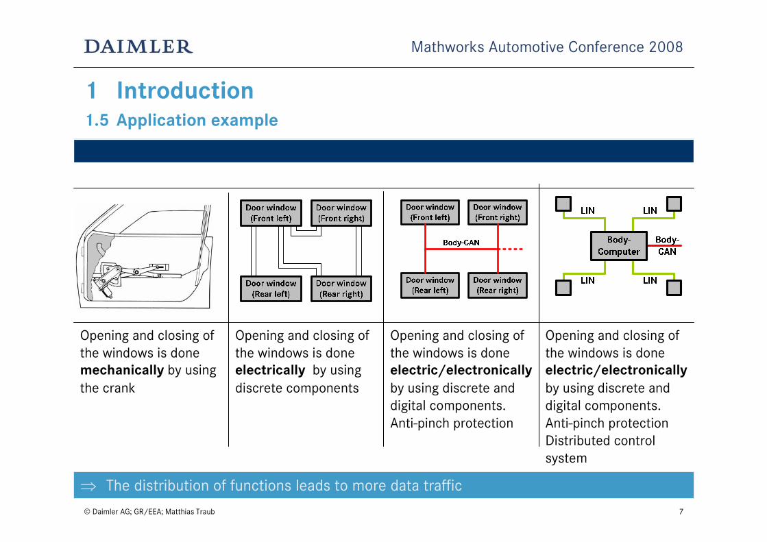
1 Introduction1.5 Application example
Opening and closing of the windows is done mechanically by using the crank
Opening and closing of the windows is done electrically by using discrete components
Opening and closing of the windows is done electric/electronicallyby using discrete and digital components.Anti-pinch protection
Opening and closing of the windows is done electric/electronicallyby using discrete and digital components.Anti-pinch protectionDistributed control system
⇒ The distribution of functions leads to more data traffic

© Daimler AG; GR/EEA; Matthias Traub 8
Mathworks Automotive Conference 2008
Motivation
Evolution up to day
Application example
Outline
1. Introduction
2. Case studyComputation platforms for automotive systems
System concept
System generation
Design flow
Conclusion

© Daimler AG; GR/EEA; Matthias Traub 9
Mathworks Automotive Conference 2008
2 Case study2.1 Computing platforms
Due to the increasing performance requirements of automotive applicationsnew hardware architectures/technologies for embedded systems are necessary,
for example multi-core processor or Field Programmable Gate Array (FPGA)
Idea
Evaluation of the FPGA-Technology for automotive applications
Main advantages of FPGAs
Parallel execution of application functionsHigh performance and flexibilityResource-efficient system partitioning

© Daimler AG; GR/EEA; Matthias Traub 10
Mathworks Automotive Conference 2008
2 Case study2.2 Cooperation project
Main focus of the project
Joint project in cooperation with the Karlsruhe Institute of Technology (KIT) since 2001
Topics of interest
Evaluation of the FPGA technology for embedded systems for automotive applications
Dynamic reconfiguration of applications Body controllersGateway systemsDesign flowAutomatic code generation of function models (C and VHDL) Does the FPGA-technology fulfill the
automotive requirements?

© Daimler AG; GR/EEA; Matthias Traub 11
Mathworks Automotive Conference 2008
2 Case study2.2 System concept
Key topics are:
Integration of interior functions on a central ECU (Body-Controller)
CAN-LIN-Gateway
LIN-Master on the Body-Controller
Seamless design flow
Hardware-software-partitioning of model-based developed functions
Standardized LIN-Slaves for sensors and actuators (from Siemens VDO)

© Daimler AG; GR/EEA; Matthias Traub 12
Mathworks Automotive Conference 2008
2 Case study2.4 Block diagram of the Body-Controller
FPGA
Application modules realized in hardware(see next slide)
Generic interface for all modules, which are connected to the GNoC
Gateway-Network-on-Chip- Packet-based
communication structure- Broadcast, unicast- Bus topology
Softcore Processor- 32-Bit Microblaze®
(Xilinx ®)- 32 kB RAM- RS232 for Debugging- Timers- Interrupt controller- External Flash 1MB
Message RAM- Message routing- Message timing- Timeout handler- Default values
Routing Engine- Signal routing- Message generation
Bus-Interfaces- CAN, LIN- USB for Debugging

© Daimler AG; GR/EEA; Matthias Traub 13
Mathworks Automotive Conference 2008
2 Case study2.5 Application modules
Hardware application module Software application module
Addr
ess
Dat
a
Example:Necessary resources for the convertibletop function (implemented on a Spartan3®
FPGA from Xilinx®): 1162 Slices
© Daimler AG; GR/EEA; Matthias Traub 14
Mathworks Automotive Conference 2008
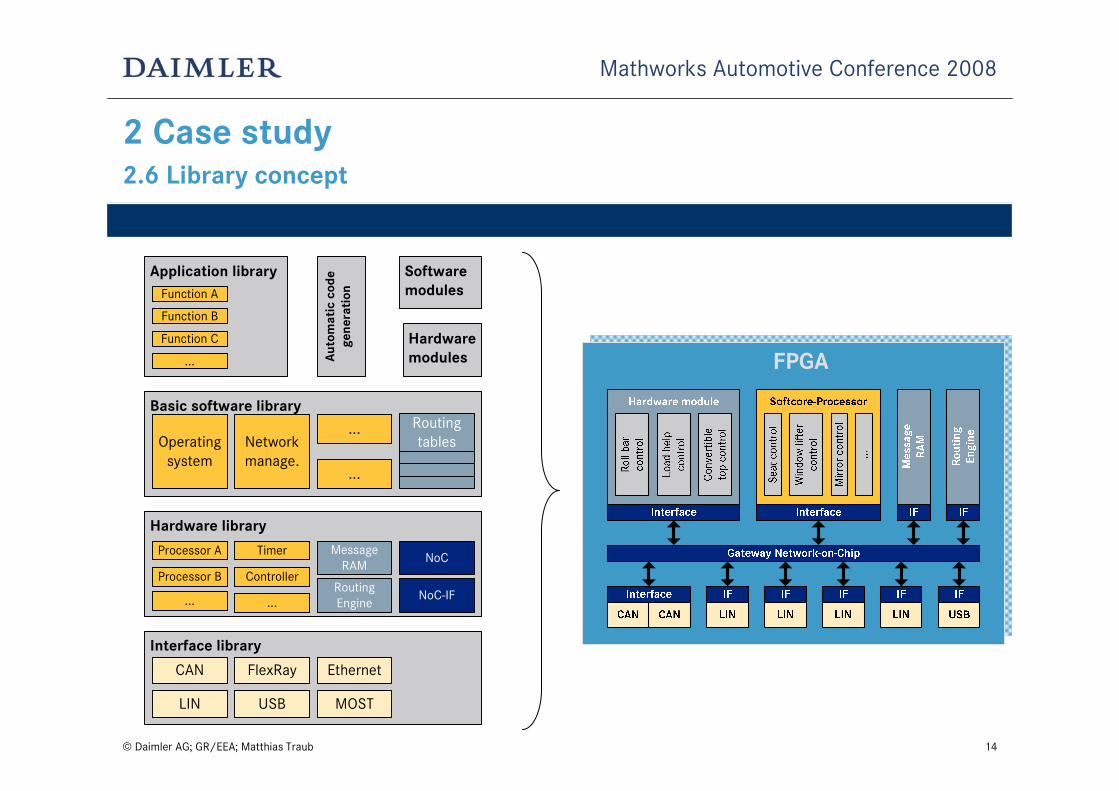
2 Case study2.6 Library concept
Interface library
Hardware library
Application library
CAN
LIN
FlexRay Ethernet
USB MOST
Processor A NoCMessage
RAM
RoutingEngine
Basic software libraryRoutingtablesOperating
system
Function A
Function B
Networkmanage.
...
...
...
Processor B
...
Timer
Controller
... NoC-IF
Auto
mat
ic c
ode
gene
rati
on
Softwaremodules
Hardwaremodules
Function C
FPGA

© Daimler AG; GR/EEA; Matthias Traub 15
Mathworks Automotive Conference 2008
2 Case study2.6 Library concept
Hardware/Software codesign for automotive applications
Interface library
Hardware library
Application library
CAN
LIN
FlexRay Ethernet
USB MOST
Processor A NoCMessage
RAM
RoutingEngine
Basic software libraryRoutingtablesOperating
system
Function A
Function B
Networkmanage.
...
...
...
Processor B
...
Timer
Controller
... NoC-IF
Auto
mat
ic c
ode
gene
rati
on
Softwaremodules
Hardwaremodules
Function C
FPGA
Window control
Roof control

© Daimler AG; GR/EEA; Matthias Traub 16
Mathworks Automotive Conference 2008
2 Case study2.7 Design flow
C-Code VHDL-Code
Automaticcode generation
Realtime WorkshopEmbedded Coder
Applicationmodels
SimulinkHDL-Coder
Testbench (ModelSim)
Breadboard assemblyVerificationand Test
Stateflow®Simulink®
© Daimler AG; GR/EEA; Matthias Traub 17
Mathworks Automotive Conference 2008
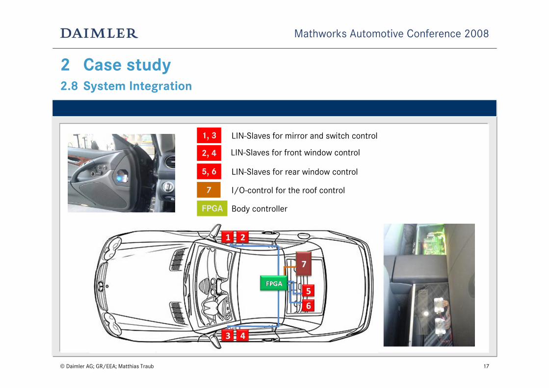
2 Case study2.8 System Integration
1, 3 LIN-Slaves for mirror and switch control
2, 4 LIN-Slaves for front window control
5, 6 LIN-Slaves for rear window control
7 I/O-control for the roof control
FPGA Body controller

© Daimler AG; GR/EEA; Matthias Traub 18
Mathworks Automotive Conference 2008
2 Case study2.9 Conclusion
The missing integration of the FPGA technology in AUTOSARand some open points of support in the standard tool flow for OEMs and suppliers
Open issues
Lessons learnedThe HDL coder
generates good results from our automotive application models, offers the advantage of FPGA-independent code generation and closes a gap in the designflow for FPGA-based automotive applications
The FPGA technology offers the possibility to speed-up of time critical functions, e.g. gateway systems,provides more flexibility during the design phaseand enables a resource-efficient system partitioning

© Daimler AG; GR/EEA; Matthias Traub 19
Mathworks Automotive Conference 2008
Thank you for your attention
Questions?