auto adaptation - m.s · pdf filefuture room temperature estimation compact hydro box unit...
TRANSCRIPT

125

126
Hydro box
EHSC/EHPX
Split type Packaged type
ECODAN“ecodan” can heat rooms and supply domestichot water, realising greater comfort and energy saving.
Both energy-saving and safe for the environment, the Mitsubishi Electric ecodan incorporates a highly efficient heat pump system that captures “the heat in the air”, a renewable energy resource. Equipped with advanced inverter control, meticulous temperature control assures comfortable heating, and its space-saving “All-in-one” indoor unit is easy to install. These energy-saving, high comfort and simple installation characteristics have drawn the ecodan heating system into the spotlight centre stage.
Excellent ecodan’s heating performance, even at low outdoor temperature!
“ecodan” – Economic, eco conscious next generation heating system
INDOOR UNIT
OUTDOOR UNIT
Cylinder unit
EHST20C/EHPT20X
SHW230 SW100/120 SW75 SW40/50 HW112/140 W85 W50
Hydro box(Reversible)
ERSC
127
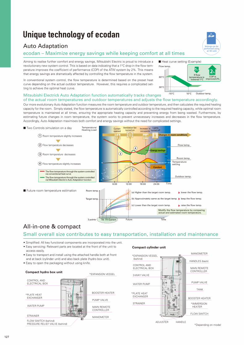
ecodan – Maximize energy savings while keeping comfort at all times
Settings can be performed using
an SD card.
Auto Adaptation
Aiming to realise further comfort and energy savings, Mitsubishi Electric is proud to introduce a revolutionary new system control. This is based on data indicating that a 1°C drop in the flow tem-perature improves the coefficient of performance (COP) of the ATW system by 2%. This means that energy savings are dramatically affected by controlling the flow temperature in the system.
In conventional system control, the flow temperature is determined based on the preset heat curve depending on the actual outdoor temperature. However, this requires a complicated set-ting to achieve the optimal heat curve.
Flow temp.
Outdoor temp.
COP isimproved 2%
If flowtemperature is
lowered 1°C60°C
30°C
-15°C 10°C
(c) Lower than the target room temp.
Room temp.
Target temp.
Time
(b) Approximately same as the target temp.
(a) Higher than the target room temp.
Future 3 points
lower the flow temp.
keep the flow temp.
raise the flow temp.
Modify the flow temperature by comparing actual and estimated room temperature.
T0 T1 Current
Our more evolutionary Auto Adaptation function measures the room temperature and outdoor temperature, and then calculates the required heating capacity for the room. Simply stated, the flow temperature is automatically controlled according to the required heating capacity, while optimal room temperature is maintained at all times, ensuring the appropriate heating capacity and preventing energy from being wasted. Furthermore, by estimating future changes in room temperature, the system works to prevent unnecessary increases and decreases in the flow temperature. Accordingly, Auto Adaptation maximises both comfort and energy savings without the need for complicated settings.
Mitsubishi Electric’s Auto Adaptation function automatically tracks changesof the actual room temperatures and outdoor temperatures and adjusts the flow temperature accordingly.
12:006:00 18:00 24:00 Time
Temperature setting
Lightsturned off
Increase inoccupants
Changes in room conditions
Energy savings
Curtainopened
Ventilation fan turned on
Flow temp.
Temperature/Heating Load
Room temp.
Outdoor temp.
The flow temperature through the system controlledvia conventional heat curve
The flow temperature through the system controlled via Mitsubishi Electric’s Auto Adaptation function
Comfort
Flow temperature decreases
Flow temperature slightly increases
Room temperature slightly increases
Room temperature decreases
1
2
3
4
2
3
4
1
*Depending on model
*PLATE HEATEXCHANGER
WATER PUMP
*EXPANSION VESSEL
CONTROL ANDELECTRICAL BOX
BOOSTER HEATER
MAIN REMOTECONTROLLER
MANOMETERFLOW SWITCH (behind)PRESSURE RELIEF VALVE (behind)
STRAINER
PUMP VALVE
Small overall size contributes to easy transportation, installation and maintenance
All-in-one & compact
*PLATE HEATEXCHANGER
3-WAY VALVE
STRAINER
ADJUSTER HANDLE
MANOMETER*EXPANSION VESSEL (behind)
MAIN REMOTECONTROLLER
CONTROL ANDELECTRICAL BOX
PUMP VALVEWATER PUMP
TANK
BOOSTER HEATER
FLOW SWITCH
HANDLES (back)
*IMMERSIONHEATER
• Simplified: All key functional components are incorporated into the unit.• Easy servicing: Relevant parts are located at the front of the unit to
access easily.• Easy to transport and install using the attached handle both at front
and at back (cylinder unit) and also back plate (hydro box unit).• Easy to open the packaging without using knife.
■ Two Controls simulation on a day
■ Future room temperature estimation
Compact hydro box unit
Compact cylinder unit
■ Heat curve setting (Example)
Unique technology of ecodan

128
ZUBADAN New Generation (Split type)Improved heating performance more efficiently
ZUBADAN is equipped with a unique “Flash Injection Circuit” that enables the system to provide powerful heating in cold regions during the winter months. And more evolved “ZUBADAN New Generation” incorporates a new compressor that is more efficient, further improving heating performance when outdoor temperatures is low. The rated heating capacity can now be maintained at-15°C even including defrost, making it possible to supply comfortable heating in ever more severe environments.
Max
. po
ssib
le f
low
tem
p. (
deg
C)
Outdoor temp.
ZUBADAN New Generation
-20°C -15°C -10°C -5°C -0°C 5°C 10°C
65
55
50
45
40
A-15/W55possible!
Ideal forDHW!
60
The Flash Injection Circuit is an original technology developed by Mitsubishi Electric. A heat exchange process at point A (heat interchanger) transforms liquid refrigerant into a two-phase, gas-liquid state and then compresses the gas-liquid refrigerant at point B (injection compressor). This circuit secures a enough flow rate of refrigerant for heating when outdoor temperatures are very low.In the ZUBADAN New Generation, the Flash Injection Circuit is more powerful by improving the heat interchanger to increase the heat-exchange-efficiency and incorporating new injection compressor to increase the compression-efficiency.These two improvements of ZUBADAN New Generation ensure reliable, efficient heating operation when outdoor temperatures are very low.
ZUBADAN New Generation
LEV B
LEV C
LEVA
Mitsubishi Electric’s Flash Injection TechnologyThe Key to High Heating Performance at Low Outdoor Temperatures
Heat Interchanger (HIC)
Heatinterchanger(HIC)Refrigerant
flow
Injection Compressor
■Flash Injection Circuit
A
A B
B
IndoorHEX
Powerreceiver
OutdoorHEX
Injection compressor(injection port)
Flash Injection Circuit
Flash Injection Circuit
Designed for Optimal Heating
ZUBADAN New Generation
ZUBADANInte
grat
ed
cap
acit
y (k
W)
Outdoor-air temperature at intake duct
W45 (according to EN 14511)
9
-7°C-15°C-20°C-25°C 0°C
101112131415
Approx. 22% higher than our previous model !
Nominal capacity can be kept at -15°C !

129
The ecodan evolution continues! For easier settings and for data loggings
SD* CARD
Stylish, easy-to-read bright LCD with ergonomically designed intuitive interface
Initial setting for ecodan is now simpler than ever before. The special software enables the required initial settings to be saved to an SD card using a personal computer. System set-up is as easy as moving the SD card from the computer to the SD card slot in the indoor unit. Compared to the previous procedure of inputting settings using the main controller at a installation field, a remarkable reduction in set-up time has been achieved. Thus, it is ideal way for busy installers.
Hydro box inside
Printed circuit board
Control and electric box SD card slot SD card SD card
Settings can be performed using
an SD card.
*SD card fanction is only used by installer.
*SD logo is a trademark of SD-3C, LLC
Settings can be performed easily andlogging operation data in SD card
can be confirmed via personal computer.
Items that can be preset
• Initial settings (time display, contact number, etc)• Heating settings - Auto Adaptation - Heat curve - Two different temperatures zones• Interlocked boiler operation settings• Holiday mode settings• Schedule timer settings• Domestic hot water settings • Legionella prevention settings
• Operation time• Defrost time• Actual temperature - Room - Flow temperature - Return temperature - Domestic hot water temperature - Outdoor temperature• Error record • Input signal etc.
Data that can be storedOperation data up to a month long can be stored ona SD card (2GB) .
Simply copying the preset data to SD card, same settings are complete in multiple units easily.
All items that are set by the main controller can be set viaa personal computer.
PAR-WT50R-E (optional)
Main controller
Wireless remote controllerReceiverPAR-WR51R-E (optional)
• Large screen and backlight for excellent visibility, even in dark environment• Multilanguage support (11 languages)• Can be removed from main unit and installed in remote location (up to 500m)• Wide range of convenient functions in response to user demand Functions settings - Weekly timer -Holiday mode -Legionella prevention -Error codes and data for serving - Two zone control -Boiler interlock -Floor drying up• Quick reading of operation data (7.5 times faster than previous model)
• Built-in room temperature sensor; easy to place in the best position to detect room temperature• Wiring work eliminated• Simple design that is easy to operate• Remote control from any room without needing to choose an installation location• Backlight and big buttons that are easy to operate• Domestic hot water boost and cancellation• Simplified holiday mode• Up to 8 controllers allowed (can be set for zone 1 or 2 individually)
Wireless remote controller (optional)
Remote controller
NEW
Main controller

130
Simultaneously making two different temperature zones assures more comfortable, highly convenient heating
ecodan makes it possible to set two temperatures which are used in two different types heat emitters in a system. The system allows adjustment of temperatures when different room temperatures are required, such as a temperature of 40°C for the living room radiator and temperature of 30°C for floor heating. Additionally, the scheduling for each zone can be set separately by main controller.
No need to replace existing boiler!Automatic switchover enables even more efficient operation
The flexibility of ecodan’s intelligent control allows the system to be combined with boiler currently in use. Additionally, this control can judge which heating source (ecodan, or boiler) to be operated according to situations (outdoor temperature, running cost, CO2 emission level etc.). Customers using a boiler can receive the energy-saving performance of ecodan.
Connect up to 6 unitsAutomatic control of multiple units to supply bigger capacity
A maximum of 6 ecodan units* can be configured according to the required heating/cooling load of the building. The most efficient number of operating units is determined automatically based on heating/cooling load. This enables ecodan to provide optimal room temperature control, and thus superior comfort for room occupants. Also incorporated is a rotation function that works to balance the running hours without depending on the operation of any one specific unit.
If one of the units malfunctions when using Multiple Unit Control, another unit can be automatically operated for back-up, thereby preventing system operation from stopping completely.
Radiator
Mixing control
Mixing tank
Hydro box
Pump
Pump
MixingvalveFTC*
40°C
30°C
Room temperaturewireless remote controller (option)
Pump
Radiator
Electricity
Other source(Gas, Oil, etc)
Hydro box
Boiler
Turning boiler on/off according to operational
conditions.
Mixing tank
FTC
Radiator
*Items such as mixing tank, mixing valve, flow switch and pumps are not included and need to be purchased locally. *FTC = Flow temperature controller
*Items such as mixing tank and pump are not included and need to be purchased locally.
*Thermostat (field supply) also can be used.
Underfloor heating
Flow switch
Flow switch
Settings can be performed using
an SD card.
Settings can be performed using
an SD card.
Intelligent system combining a boiler with ecodan
Intelligent boiler interlock
Two zone control
Settings can be performed using
an SD card.
Multiple unit control
*Only same models (same capacity) are available.
■ Multiple unit control
■ Two temperature zones
■ Two temperature zones
Multiple unit control
Main RC
FTCslave
master
14kW + 14kW + 14kW + 14kW + 14kW + 14kW
FTCslave
FTCslave
FTCslave
FTCslave
FTCslave
FTC
COP ratio (%)
Total Capacity
Multiple unit control
100
One large unit control
Always high efficient operation !Inefficient operation at low capacity.ON/OFF control
1 unit 2 units 3 units 4 units 5 units 6 units
131
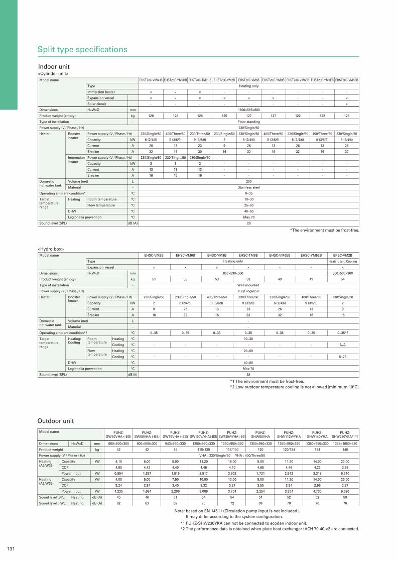
Split type specifications
H×W×D
<Cylinder unit>
<Hydro box>
Model name
Dimensions
Product weight (empty)
Type of installation
Power supply (V / Phase / Hz)
Heater
Domestichot water tank
Operating ambient condition*
Target temperaturerange
Sound level (SPL)
EHST20C-VM6HB
×
×
-
128
230/Single/50
6 (2/4/6)
26
32
230/Single/50
3
13
16
EHST20C-YM9HB
×
×
-
128
400/Three/50
9 (3/6/9)
13
16
230/Single/50
3
13
16
EHST20C-TM9HB
×
×
-
128
230/Three/50
9 (3/6/9)
23
30
230/Single/50
3
13
16
EHST20C-VM2B
-
×
-
125
230/Single/50
2
9
16
-
-
-
-
EHST20C-VM6B
-
×
-
127
230/Single/50
6 (2/4/6)
26
32
-
-
-
-
EHST20C-YM9B
-
×
-
127
400/Three/50
9 (3/6/9)
13
16
-
-
-
-
Heating only
1600×595×680
Floor standing
230/Single/50
200
Stainless steel
0~35
10~30
25~60
40~60
Max 70
28
EHST20C-VM6EB
-
-
-
122
230/Single/50
6 (2/4/6)
26
32
-
-
-
-
EHST20C-YM9EB
-
-
-
122
400/Three/50
9 (3/6/9)
13
16
-
-
-
-
EHST20C-VM6SB
-
×
×
128
230/Single/50
6 (2/4/6)
26
32
-
-
-
-
Type
Immersion heater
Expansion vessel
Solar circuit
H×W×D
Power supply (V / Phase / Hz)
Capacity
Current
Breaker
Power supply (V / Phase / Hz)
Capacity
Current
Breaker
Room temperature
Flow temperature
mm
kg
-
kW
A
A
kW
A
A
L
-
°C
°C
°C
°C
°C
dB (A)
Booster
Immersion
Volume (net)
Material
Heating
DHW
Legionella prevention
Model name
Dimensions
Product weight (empty)
Type of installation
Power supply (V / Phase / Hz)
Heater
Domestichot water tank
Operating ambient condition*1
Target temperaturerange
Sound level (SPL)
EHSC-VM6B
×
53
230/Single/50
6 (2/4/6)
26
32
0~35
-
-
EHSC-VM2B
×
51
230/Single/50
2
9
16
0~35
-
-
EHSC-YM9B
×
53
400/Three/50
9 (3/6/9)
13
16
0~35
-
-
EHSC-TM9B
×
53
230/Three/50
9 (3/6/9)
23
32
0~35
-
-
EHSC-VM6EB
-
49
230/Single/50
6 (2/4/6)
26
32
0~35
-
-
Wall mounted
230/Single/50
-
-
10~30
25~60
40~60
Max 70
28
800×530×360
EHSC-YM9EB
-
49
400/Three/50
9 (3/6/9)
13
16
0~35
-
-
ERSC-VM2B
Heating and Cooling
×
860×530×360
54
230/Single/50
2
9
16
0~35*2
N/A
5~25
Type
Expansion vessel
H×W×D
Power supply (V / Phase / Hz)
Capacity
Current
Breaker
Room
Flow
mm
kg
-
kW
A
A
L
-
°C
°C
°C
°C
°C
°C
°C
dB (A)
Booster
Volume (net)
Material
Heating/
DHW
Legionella prevention
Model name
Dimensions
Product weight
Power supply (V / Phase / Hz)
Heating(A7/W35)
Heating(A2/W35)
Sound level (SPL)
Sound level (PWL)
PUHZ-SW40VHA (-BS)
600×800×300
42
4.10
4.80
0.854
4.00
3.24
1.235
45
62
PUHZ-SW50VHA (-BS)
600×800×300
42
6.00
4.42
1.357
5.00
2.97
1.684
46
63
PUHZ-SW75VHA (-BS)
943×950×330
75
8.00
4.40
1.819
7.50
3.40
2.206
51
69
PUHZ-SW100V/YHA (-BS)
1350×950×330
118 / 130
11.20
4.45
2.517
10.00
3.32
3.009
54
70
PUHZ-SW120V/YHA (-BS)
1350×950×330
118 / 130
16.00
4.10
3.903
12.00
3.24
3.704
54
72
VHA : 230/Single/50 YHA : 400/Three/50
PUHZ-SHW80VHA
1350×950×330
120
8.00
4.65
1.721
8.00
3.55
2.254
51
69
PUHZ-SHW112V/YHA
1350×950×330
120/134
11.20
4.46
2.512
11.20
3.34
3.354
52
70
PUHZ-SHW140YHA
1350×950×330
134
14.00
4.22
3.318
14.00
2.96
4.730
52
70
PUHZ-SHW230YKA*1 *2
1338×1050×330
148
23.00
3.65
6.310
23.00
2.37
9.690
59
76
mm
kg
kW
kW
kW
kW
dB (A)
dB (A)
Capacity
COP
Power input
Capacity
COP
Power input
Heating
Heating
Indoor unit
Outdoor unit
Heating only
Note: based on EN 14511 (Circulation pump input is not included.). It may differ according to the system configuration.
*The environment must be frost-free.
*1 The environment must be frost-free.*2 Low outdoor temperature cooling is not allowed (minimum 10°C).
*1 PUHZ-SHW230YKA can not be connected to ecodan indoor unit.*2 The performance data is obtained when plate heat exchanger (ACH 70-40)×2 are connected.
Heating
Cooling
Heating
Cooling
heater
heater
heater
Cooling temperature
temperature

132
<Indoor unit>Parts name Model name Specification Cylinder unit
EHST20C-VM6HB
EHST20C-YM9HB
EHST20C-TM9HB
EHST20C-VM2B
EHST20C-VM6B
EHST20C-YM9B
EHST20C-VM6EB
EHST20C-YM9EB
EHST20C-VM6SB
EHSC-VM2B
EHSC-VM6B
EHSC-YM9B
EHSC-TM9B
EHSC-VM6EB
EHSC-YM9EB
ERSC-VM2B
×
×
×
×
-
×
-
×
×
×
×
×
×
×
-
×
-
×
×
×
×
×
×
×
-
×
-
×
×
×
×
×
×
×
-
×
×
×
×
×
×
×
×
×
-
×
×
×
×
×
×
×
×
×
-
×
×
×
×
×
×
×
×
×
-
×
×
×
×
×
×
×
×
×
-
×
×
×
×
×
×
×
×
×
-
×
×
×
×
×
×
×
×
×
×
×
-
×
×
×
×
×
×
×
×
×
-
×
×
×
×
×
×
×
×
×
-
×
×
×
×
×
×
×
×
×
-
×
×
×
×
×
×
×
×
×
-
×
×
×
×
×
×
×
×
×
-
×
×
×
×
×
×
×
×
×
-
×
×
×
Hydro box
Wirelss remote controller
Wirelss receiver
Thermistors
Immersion heater
Joint pipe
Wi-Fi INTERFACE
PAR-WT50R-E
PAR-WR51R-E
PAC-SE41TS-E
PAC-TH011-E
PAC-TH011TK-E
PAC-TH011HT-E
PAC-IH03V-E
PAC-SH30RJ-E
PAC-SH50RJ-E
PAC-WF010-E
Parts name Air discharge guide PAC-SG58SG-E 1
22484
Air discharge guideSupport (For the upper and lower sides)Support (For right and left)Attachment screw (5×10)Attachment screw (4×10)Spacer
Model name Contents Q’ty
Capacity step controlinterface
Flow temperaturecontrollers
System controllers
Thermistors
PAC-IF010-EPAC-IF011B-E
PAC-IF020-EPAC-IF021B-E
PAC-IF032B-E
PAC-IF051B-E
PAC-SIF051B-E
PAC-TH011-EPAC-TH011HT-EPAC-TH011TK-E
PC boardPC boardCaseThermistorPC boardPC boardCaseThermistorRemote controllerRemote controller cable (5m)PC boardCaseThermistorRemote controllerRemote controller cable (5m)PC boardCaseThermistorRemote controllerRemote controller cable (10m)SD memory cardPC boardCaseThermistorRemote controller cable (10m)SD memory cardThermistor for buffer and zone (flow and return temp.) Thermistor for tank temp.Thermistor for boiler (flow and return temp.)
10*1
112
10*1
112111131111211111211
20*2
20*2
10*3
Parts name Model name Contents Q’tyCentralised drain pan
Control /Service tool
PAC-SG63DP-EPAC-SG64DP-EPAC-SK52ST
Centralised drain panCentralised drain panControl/Service Tool
111
Optional parts
Contents
Air discharge guide
Air protection guide
Drain socket
PAC-SG59SG-E
PAC-SG96SG-E
PAC-SG56AG-E
PAC-SH63AG-E
PAC-SH95AG-E
PAC-SG61DS-E
PAC-SH71DS-E
Air discharge guideAttachment screw (5×35)SpacerAir discharge guideSupportScrew (5×15)WasherSpring washerFront plateSide plate Side plateConnecting plate Mounting screw (4×10)Mounting screw (4×12)Washer (for screw 4×12)Air guideMounting screw (5×15)WasherSpring washerAir guideMounting screw (5×15)WasherSpring washerDrain socketDrain cap (ø33)Heat insulatorBandDrain socketDrain cap (ø33/ø12)Heat insulatorBand
14411
1212121222
14441444166615281728
For room temp.
For buffer and zone (flow and return temp.)
For tank temp.
For boiler (flow and return temp.)
1Ph 3kW
For PUHZ-SW40/50VHA (-BS) ø9.52 ø6.35
For PUHZ-SW40/50VHA (-BS) ø15.88 ø12.70
<Interface/Flow temperature controller>Parts name
*1 PAC-IF010-E and PAC-IF020-E are only for manufacturer’s preloading.*2 PAC-TH011-E is required.
*1 One carton contains 10 PC boards.*2 Two thermistors per package: 10 packages per carton*3 One thermistor per package: 10 packages per carton
Model name Power inverter ZUBADAN
PUHZ-SW40VHA(-BS)
×
×
×
×
×
×
×
×
Capacity step control interface
Flow temperature controllers
System controllers
Thermistors
PAC-IF010-E*1
PAC-IF011B-E
PAC-IF020-E*1
PAC-IF021B-E
PAC-IF032B-E
PAC-IF051B-E
PAC-SIF051B-E
PAC-TH011-E
Description
10 PC boards w/o case
1 PC board w/ case
10 PC boards w/o case
1 PC board w/ case
1 PC board w/ case
1 PC board w/ case
1 PC board w/ case
*2
PUHZ-SW50VHA(-BS)
×
×
×
×
×
×
×
×
PUHZ-SW75VHA(-BS)
×
×
×
×
×
×
×
×
PUHZ-SW100V/YHA(-BS)
×
×
×
×
×
×
×
×
PUHZ-SW120V/YHA(-BS)
×
×
×
×
×
×
×
×
PUHZ-SHW80VHA
×
×
×
×
×
×
×
×
PUHZ-SHW112V/YHA
×
×
×
×
×
×
×
×
PUHZ-SHW140YHA
×
×
×
×
×
×
×
×
PUHZ-SHW230YKA
×
×
×
×
×
×
×
×
*2
*2
*2
*2
*2
*2
*2
*2
*2
*2
*2
*2
*2
*2
*2
*2
*2
<Outdoor unit>Parts name
*1 PUHZ-SHW230YKA can not be connected to ecodan indoor unit.
Model name Power inverter ZUBADAN
PUHZ-SW40VHA(-BS)
×
×
-
-
×
-
-
-
×
×
-
×
Connector for drain hose heater signal output
Air discharge guide
Air protection guide
Drain socket
Centralised drain pan
Control /Service tool
PAC-SE60RA-E
PAC-SG58SG-E
PAC-SG59SG-E
PAC-SG96SG-E
PAC-SG56AG-E
PAC-SH63AG-E
PAC-SH95AG-E
PAC-SG61DS-E
PAC-SH71DS-E
PAC-SG63DP-E
PAC-SG64DP-E
PAC-SK52ST
*1PUHZ-
SW50VHA(-BS)
×
×
-
-
×
-
-
-
×
×
-
×
PUHZ-SW75VHA(-BS)
×
-
×
-
-
×
-
×
-
-
×
×
PUHZ-SW100V/YHA(-BS)
×
-
×
-
-
×
-
×
-
-
×
×
PUHZ-SW120V/YHA(-BS)
×
-
×
-
-
×
-
×
-
-
×
×
PUHZ-SHW80VHA
×
-
×
-
-
×
-
-
-
-
-
×
PUHZ-SHW112V/YHA
×
-
×
-
-
×
-
-
-
-
-
×
PUHZ-SHW140YHA
×
-
×
-
-
×
-
-
-
-
-
×
PUHZ-SHW230YKA
×
-
-
×
-
-
×
-
-
-
-
×

133
Packaged type specifications
H×W×D
<Cylinder unit>
<Hydro box>
Model name
Dimensions
Product weight (empty)
Type of installation
Power supply (V / Phase / Hz)
Heater
Domestichot water tank
Operating ambient condition*
Target temperaturerange
Sound level (SPL)
EHPT20X-VM2HB
×
×
113
230/Single/50
2
9
16
230/Single/50
3
13
16
EHPT20X-VM6HB
×
×
115
230/Single/50
6 (2/4/6)
26
32
230/Single/50
3
13
16
EHPT20X-YM9HB
×
×
115
400/Three/50
9 (3/6/9)
13
16
230/Single/50
3
13
16
Heating only
1600×595×680
Floor standing
230/Single/50
200
Stainless steel
0~35
10~30
25~60
40~60
Max 70
28
EHPT20X-TM9HB
×
×
115
230/Three/50
9 (3/6/9)
23
30
230/Single/50
3
13
16
EHPT20X-VM6B
-
×
114
230/Single/50
6 (2/4/6)
26
32
-
-
-
-
EHPT20X-YM9B
-
×
114
400/Three/50
9 (3/6/9)
13
16
-
-
-
-
Type
Immersion heater
Expansion vessel
H×W×D
Power supply (V / Phase / Hz)
Capacity
Current
Breaker
Power supply (V / Phase / Hz)
Capacity
Current
Breaker
Room temperature
Flow temperature
mm
kg
-
kW
A
A
kW
A
A
L
-
°C
°C
°C
°C
°C
dB (A)
Booster heater
Immersion heater
Volume (net)
Material
Heating
DHW
Legionella prevention
Model name
Dimensions
Product weight (empty)
Type of installation
Power supply (V / Phase / Hz)
Heater
Domestichot water tank
Operating ambient condition*
Target temperaturerange
Sound level (SPL)
EHPX-VM2B
×
39
230/Single/50
2
9
16
EHPX-VM6B
Heating only
×
800×530×360
41
Wall mounted
230/Single/50
230/Single/50
6 (2/4/6)
26
32
-
-
0~35
10~30
25~60
40~60
Max 70
28
EHPX-YM9B
×
41
400/Three/50
9 (3/6/9)
13
16
Type
Expansion vessel
H×W×D
Power supply (V / Phase / Hz)
Capacity
Current
Breaker
Room temperature
Flow temperature
mm
kg
-
kW
A
A
L
-
°C
°C
°C
°C
°C
dB (A)
Booster heater
Volume (net)
Material
Heating
DHW
Legionella prevention
Model name
Dimensions
Product weight
Power supply (V / Phase / Hz)
Heating(A7/W35)
Heating(A2/W35)
Sound level (SPL)
Sound level (PWL)
PUHZ-W50VHA (-BS)
740×950×330
64
5.00
4.10
1.220
5.00
3.13
1.597
46
61
PUHZ-W85VHA2 (-BS)
943×950×330
79
9.00
4.18
2.153
8.50
3.17
2.681
48
66
PUHZ-HW112YHA2 (-BS)
1350×1020×330
148
VHA : 230/Single/50 YHA : 400/Three/50
11.20
4.42
2.533
11.20
3.11
3.601
53
67
PUHZ-HW140VHA2 (-BS)
1350×1020×330
134
14.00
4.25
3.294
14.00
3.11
4.501
53
67
PUHZ-HW140YHA2 (-BS)
1350×1020×330
148
14.00
4.25
3.294
14.00
3.11
4.501
53
67
mm
kg
kW
kW
kW
kW
dB (A)
dB (A)
Capacity
COP
Power input
Capacity
COP
Power input
Heating
Heating
Indoor unit
Outdoor unit
Note: based on EN 14511 (Circulation pump input is included.). It may differ according to the system configuration.
*The environment must be frost-free.
*The environment must be frost-free.

134
<Indoor unit>Parts name Model name Specification Cylinder unit
EHPT20X-VM2HB
×
×
×
×
-
×
-
×
×
EHPT20X-VM6HB
×
×
×
×
-
×
-
-
×
EHPT20X-YM9HB
×
×
×
×
-
×
-
-
×
EHPT20X-TM9HB
×
×
×
×
-
×
-
-
×
EHPT20X-VM6B
×
×
×
×
-
×
×
-
×
EHPT20X-YM9B
×
×
×
×
-
×
×
-
×
EHPX-VM2B
×
×
×
×
×
×
-
-
×
EHPX-VM6B
×
×
×
×
×
×
-
-
×
EHPX-YM9B
×
×
×
×
×
×
-
-
×
Hydro box
Wirelss remote controller
Wirelss receiver
Thermistors
Immersion heater
EHPT accessories for UK
Wi-Fi INTERFACE
PAR-WT50R-E
PAR-WR51R-E
PAC-SE41TS-E
PAC-TH011-E
PAC-TH011TK-E
PAC-TH011HT-E
PAC-IH03V-E
PAC-WK01UK-E
PAC-WF010-E
Capacity step controlinterface
Flow temperaturecontrollers
PAC-IF010-E
PAC-IF011B-E
PAC-IF020-E
PAC-IF021B-E
PAC-IF032B-E
PC board
PC board
Case
Thermistor
PC board
PC board
Case
Thermistor
Remote controller
Remote controller cable (5m)
PC board
Case
Thermistor
Remote controller
Remote controller cable (5m)
10*1
1
1
2
10*1
1
1
2
1
1
1
1
3
1
1
Parts name
Air discharge guide
Air protection guide
Drain socket
Centralised drain pan
PAC-SG59SG-E
PAC-SH63AG-E
PAC-SG61DS-E
PAC-SG64DP-E
Air discharge guide
Attachment screw (5×35)
Spacer
Air guide
Mounting screw (5×15)
Washer
Spring washer
Drain socket
Drain cap (ø33)
Heat insulator
Band
Centralised drain pan
1
4
4
1
4
4
4
1
5
2
8
1 Thermistors PAC-TH011-E
PAC-TH011HT-E
PAC-TH011TK-E
Thermistor for buffer and zone (flow and return temp.)
Thermistor for tank temp.
Thermistor for boiler (flow and return temp.)
20*2
20*2
10*3
Optional parts
Contents
For room temp.
For buffer and zone (flow and return temp.)
For tank temp.
For boiler (flow and return temp.)
1Ph 3kW
<Interface/Flow temperature control>Parts name
*1 PAC-IF010-E and PAC-IF020-E are only for manufacturer’s preloading.*2 PAC-TH011-E is required.
*1 One carton contains 10 PC boards.*2 Two thermistors per package: 10 packages per carton*3 One thermistor per package: 10 packages per carton
Model name Power inverter ZUBADAN
PUHZ-W50VHA(-BS)
×
×
×
×
×
×
×
×
Capacity step control interface
Flow temperature controllers
Thermistors
System controllers
PAC-IF010-E*1
PAC-IF011B-E
PAC-IF020-E*1
PAC-IF021B-E
PAC-IF032B-E
PAC-IF051B-E
PAC-SIF051B-E
PAC-TH011-E
Description
10 PC boards w/o case
1 PC board w/ case
10 PC boards w/o case
1 PC board w/ case
1 PC board w/ case
1 PC board w/ case
1 PC board w/ case
*2
*2
PUHZ-W85VHA2(-BS)
×
×
×
×
×
×
×
×
*2
*2
PUHZ-HW112YHA2(-BS)
×
×
×
×
×
×
×
×
*2
*2
PUHZ-HW140VHA2(-BS)
×
×
×
×
×
×
×
×
*2
*2
PUHZ-HW140YHA2(-BS)
×
×
×
×
×
×
×
×
*2
*2
<Outdoor unit>Parts name Model name Power inverter ZUBADAN
PUHZ-W50VHA(-BS)
×
×
×
×
×
Connector for drain hose heater signal output
Air discharge guide
Air protection guide
Drain socket
Centralised drain pan
PAC-SE60RA-E
PAC-SG59SG-E
PAC-SH63AG-E
PAC-SG61DS-E
PAC-SG64DP-E
PUHZ-W85VHA2(-BS)
×
×
×
×
×
PUHZ-HW112YHA2(-BS)
×
×
×
-
-
PUHZ-HW140VHA2(-BS)
×
×
×
-
-
PUHZ-HW140YHA2(-BS)
×
×
×
-
-
Model name Contents Q’ty Parts name
System controllers PAC-IF051B-E
PAC-SIF051B-E
PC board
Case
Thermistor
Remote controller
Remote controller cable (10m)
SD memory card
PC board
Case
Thermistor
Remote controller cable (10m)
SD memory card
1
1
2
1
1
1
1
1
2
1
1
Model name Contents Q’ty

135
Using waste heat from air conditioners to heat water
Mr. SLIM+ – The smart air conditioning and hot-water supply system conceived from eco-conscious ideas
INDOOR UNIT
ECODAN AIR-TO-WATER INDOOR UNIT OUTDOOR UNIT
PLA-ZRP71BA
PCA-RP71KA
PEAD-RP71JAQ
PKA-RP71KAL
PSA-RP71KA
PUHZ-FRP71VHA
PCA-RP71HA
PEAD-RP71JALQ
EHSC-VM2BEHSC-VM6BEHSC-YM9BEHSC-TM9BEHSC-VM6EBEHSC-YM9EB
Cylinder unitHydro box
EHST20C-VM2BEHST20C-VM6BEHST20C-YM9BEHST20C-VM6EBEHST20C-YM9EBEHST20C-VM6SBEHST20C-VM6HBEHST20C-YM9HBEHST20C-TM9HB
*2012 B generation split type models*Reversible model cannot be connected
Mr.SLIM+

136
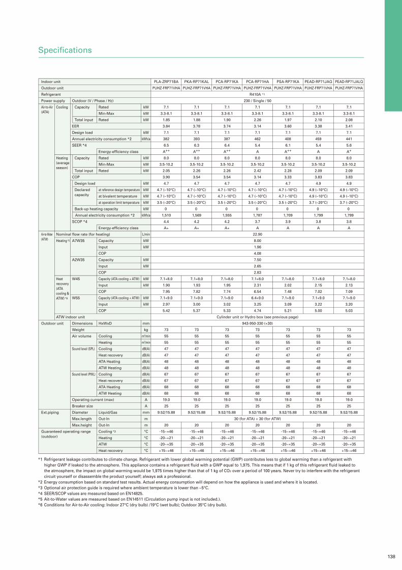
In conventional systems, the air-heat exchanger in the outdoor unit works as a condenser during air conditioning operation. The heat of the indoor-air is transferred to the outside-air and exhausted as waste heat. The new circuit in Mr.SLIM+ uses a water-heat exchanger for supplying hot water as the condenser. When the air conditioning and hot-water sys-tems are running at the same time, heat is recycled and used rather than being exhausted as waste heat. “COP7.0* attained at water temperature of 45°C and standard air conditioning operation conditions” Traditionally, when using a hot-water supply system where the air-heat exchanger is in the outdoor unit, operation may not be possible when the out-side temperature is very high. However, since Mr.SLIM+ uses the Air-to-Air indoor unit for air conditioning operation and there’s no heat exchange with outside-air, it’s possible to use the hot-water supply system even if the ambient temperature is very high. “Hot-water supply is possible (in heat recovery mode) even when the temperature outside is high (outside temperature = 46°C)”*Conditions for Air-to-Air coolong: Indoor 27°C (dry bulb) / 19°C (wet bulb) ; Outdoor 35°C (dry bulb) *Water temperrature: 45°C
Conventional system
Hybrid heat recovery system
More ecologicalHeat recovery function recycles waste heat from air conditioners
Air conditioners normally exhaust hot air from the outdoor unit as waste heat in cooling operation. With Mr. SLIM+, however, the heat that is ex-hausted by conventional air conditioning systems is recycled and simultaneously transferred to the hot-water supply system, where it’s used to heat water.
Air conditioning and hot-water supply in one system – Installation space reducedSpace savings
Mr.SLIM+ utilizes an evolutionary “2-in-1” design that combines two original Mitsubishi Electric system technologies (i.e., Air-to- Air and Air-to-Water) using a single outdoor unit.
Mitsubishi Electric’s legendary Air-to-Air and Air-to-Water systems have been integrated into a new configuration in which two sys-tems share just one outdoor unit. The installation area required outside is cut in half, realizing a space savings of 50%.
Save on installation
Previously, two systems including two separate outdoor units were required. But the all-new Mr.SLIM+ simplifies everything into a single system configuration, improving reliability and quality by reducing installation time. That results in savings in both time and money, which are passed on to our customers.
Save on construction

137
1 Unit, 2 Roles – Total Comfort Year-roundAir conditioning and hot-water supply matching the needs of each room
Mr.SLIM / Air to Air (Air Cooling) Mr.SLIM / Air to Air (Air Heating)
ecodan / Air to Water (Hot-water heating + DHW) Mr.SLIM + ecodan / Air to Air (Air Cooling) + DHW
Air-to-Air cooling using Air-to-Air indoor unit Air-to-Air heating using Air-to-Air indoor unit
Air-to-Water operation using Air-to-Water indoor unit Heat recovery using both Air-to-Air and Air-to-Water indoor units
All-in-one outdoor unit (air conditioning, hot-water supply and hot-water heating)
Mr.SLIM for Air-to-Air
Mr.SLIM+ utilizes a duct system that enables the air conditioning or heating of multiple rooms, and other indoor unit type systems that is possible to fit vari-ous applications.
ecodan for Air-to-Water
✓Hot-water supply (Domestic Hot-water supply)✓Hot-water heating for multiple rooms Mr.SLIM+ utilizes ecodan system that is possible to make Domestic Hot-water and to operate Hot-water heating.
Various operations
138
Specifications
PLA-ZRP71BA
PUHZ-FRP71VHA
7.1
3.3-8.1
1.85
3.84
7.1
382
6.5
A++
8.0
3.5-10.2
2.05
3.90
4.7
4.7 (–10°C)
4.7 (–10°C)
3.5 (–20°C)
0
1,510
4.4
A+
7.1+8.0
1.90
7.95
7.1+9.0
2.97
5.42
73
55
55
47
47
48
48
67
67
68
68
19.0
25
9.52/15.88
20
-15~+46
-20~+21
-20~+35
+15~+46
Indoor unit
Outdoor unit
Refrigerant
Power supply
Air-to-Air(ATA)
Air-to-Water(ATW)
Outdoor unit
Ext.piping
Guaranteed operating range(outdoor)
Cooling
Heating(average season)
Nominal flow rate (for heating)
Heating *5
Heat recovery(ATA cooling &ATW)
*6
ATW indoor unit
Outdoor (V / Phase / Hz)
Capacity
Total input
EER
Design load
Annual electricity consumption *2
SEER *4
Capacity
Total input
COP
Design load
Declared
capacity
Back-up heating capacity
Annual electricity consumption *2
SCOP *4
A7W35
A2W35
W45
W55
Dimensions
Weight
Air volume
Sound level (SPL)
Sound level (PWL)
Operating current (max)
Breaker size
Diameter
Max.length
Max.height
kW
kW
kW
kW
kWh/a
kW
kW
kW
kW
kW
kW
kW
kW
kWh/a
L/min
kW
kW
kW
kW
kW
kW
kW
kW
mm
kg
m3/min
m3/min
dB(A)
dB(A)
dB(A)
dB(A)
dB(A)
dB(A)
dB(A)
dB(A)
A
A
mm
m
m
°C
°C
°C
°C
Rated
Min-Max
Rated
Energy-efficiency class
Rated
Min-Max
Rated
at reference design temperature
at bivalent temperature
at operation limit temperature
Energy-efficiency class
Capacity
Input
COP
Capacity
Input
COP
Capacity (ATA cooling + ATW)
Input
COP
Capacity (ATA cooling + ATW)
Input
COP
HxWxD
Cooling
Heating
Cooling
Heat recovery
ATA Heating
ATW Heating
Cooling
Heat recovery
ATA Heating
ATW Heating
Liquid/Gas
Out-In
Out-In
Cooling *3
Heating
ATW
Heat recovery
PKA-RP71KAL
PUHZ-FRP71VHA
7.1
3.3-8.1
1.88
3.78
7.1
393
6.3
A++
8.0
3.5-10.2
2.26
3.54
4.7
4.7 (–10°C)
4.7 (–10°C)
3.5 (–20°C)
0
1,569
4.2
A+
7.1+8.0
1.93
7.82
7.1+9.0
3.00
5.37
73
55
55
47
47
48
48
67
67
68
68
19.0
25
9.52/15.88
20
-15~+46
-20~+21
-20~+35
+15~+46
PCA-RP71KA
PUHZ-FRP71VHA
7.1
3.3-8.1
1.90
3.74
7.1
387
6.4
A++
8.0
3.5-10.2
2.26
3.54
4.7
4.7 (–10°C)
4.7 (–10°C)
3.5 (–20°C)
0
1,555
4.2
A+
7.1+8.0
1.95
7.74
7.1+9.0
3.02
5.33
73
55
55
47
47
48
48
67
67
68
68
19.0
25
9.52/15.88
20
-15~+46
-20~+21
-20~+35
+15~+46
PCA-RP71HA
PUHZ-FRP71VHA
R410A *1
230 / Single / 50
7.1
3.3-8.1
2.26
3.14
7.1
462
5.4
A
8.0
3.5-10.2
2.42
3.14
4.7
4.7 (–10°C)
4.7 (–10°C)
3.5 (–20°C)
0
1,787
3.7
A
22.90
8.00
1.96
4.08
7.50
2.65
2.83
7.1+8.0
2.31
6.54
6.4+9.0
3.25
4.74
Cylinder unit or Hydro box (see previous page)
943-950-330 (+30)
73
55
55
47
47
48
48
67
67
68
68
19.0
25
9.52/15.88
30 (for ATA) + 30 (for ATW)
20
-15~+46
-20~+21
-20~+35
+15~+46
PSA-RP71KA
PUHZ-FRP71VHA
7.1
3.3-8.1
1.97
3.60
7.1
408
6.1
A++
8.0
3.5-10.2
2.28
3.33
4.7
4.7 (–10°C)
4.7 (–10°C)
3.5 (–20°C)
0
1,709
3.9
A
7.1+8.0
2.02
7.48
7.1+9.0
3.09
5.21
73
55
55
47
47
48
48
67
67
68
68
19.0
25
9.52/15.88
20
-15~+46
-20~+21
-20~+35
+15~+46
PEAD-RP71JAQ
PUHZ-FRP71VHA
7.1
3.3-8.1
2.10
3.38
7.1
459
5.4
A
8.0
3.5-10.2
2.09
3.83
4.9
4.9 (–10°C)
4.9 (–10°C)
3.7 (–20°C)
0
1,799
3.8
A
7.1+8.0
2.15
7.02
7.1+9.0
3.22
5.00
73
55
55
47
47
48
48
67
67
68
68
19.0
25
9.52/15.88
20
-15~+46
-20~+21
-20~+35
+15~+46
PEAD-RP71JALQ
PUHZ-FRP71VHA
7.1
3.3-8.1
2.08
3.41
7.1
441
5.6
A+
8.0
3.5-10.2
2.09
3.83
4.9
4.9 (–10°C)
4.9 (–10°C)
3.7 (–20°C)
0
1,799
3.8
A
7.1+8.0
2.13
7.09
7.1+9.0
3.20
5.03
73
55
55
47
47
48
48
67
67
68
68
19.0
25
9.52/15.88
20
-15~+46
-20~+21
-20~+35
+15~+46
*1
*2*3*4*5*6
Refrigerant leakage contributes to climate change. Refrigerant with lower global warming potential (GWP) contributes less to global warming than a refrigerant with higher GWP if leaked to the atmosphere. This appliance contains a refrigerant fluid with a GWP equal to 1,975. This means that if 1 kg of this refrigerant fluid leaked to the atmosphere, the impact on global warming would be 1,975 times higher than that of 1 kg of CO2 over a period of 100 years. Never try to interfere with the refrigerant circuit yourself or disassemble the product yourself; always ask a professional.Energy consumption based on standard test results. Actual energy consumption will depend on how the appliance is used and where it is located.Optional air protection guide is required where ambient temperature is lower than –5°C.SEER/SCOP values are measured based on EN14825.Ait-to-Water values are measured based on EN14511 (Circulation pump input is not included.).Conditions for Air-to-Air cooling: Indoor 27°C (dry bulb) /19°C (wet bulb); Outdoor 35°C (dry bulb).