auto diagnosis test #4 review
TRANSCRIPT

Auto Diagnosis Test #4 Review Your own handwritten notes may be used for the 1 st 10 minutes of the test
Based on Chapters 17 & 18 & 19 & Lab Demonstrations
For the Most Effective Personal Review, Look Over the OnLine Study Guide Multimedia
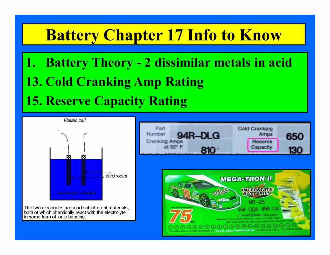
Battery Chapter 17 Info to Know 1. Battery Theory 2 dissimilar metals in acid 13. Cold Cranking Amp Rating 15. Reserve Capacity Rating

Battery Chapter 17 Info to Know 10. Open Circuit Battery Voltage 32. Baking Soda to Neutralize Battery Acid 15. Discharged Battery has Lower Specific Gravity

Battery Chapter 17 Info to Know 21. Electrolyte 36% H 2 SO 4 & 64% H 2 O 23. Lead Sulfate forming on plates = hard to charge 35. Specific Gravity
Water has a S.G. of 1.000 Electrolyte has a S.G. of 1.2601.28
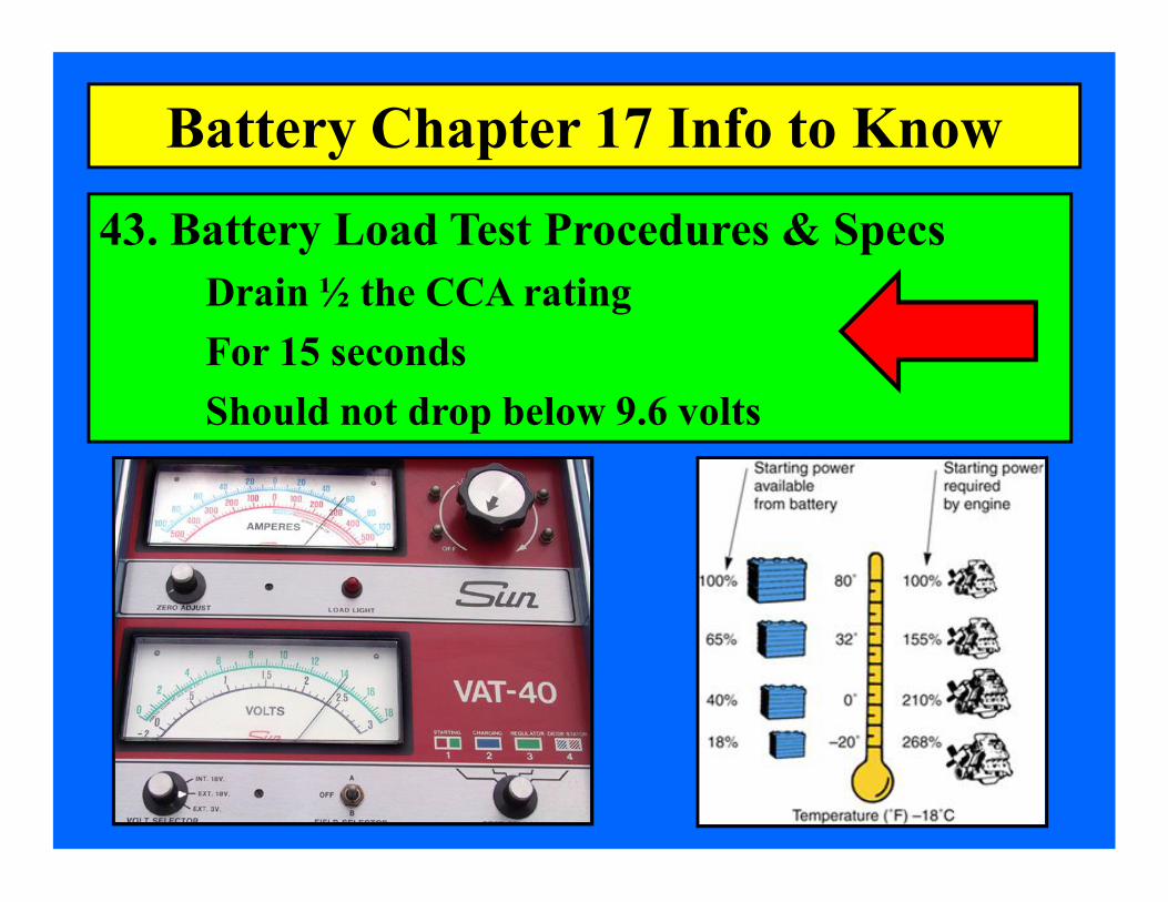
43. Battery Load Test Procedures & Specs Drain ½ the CCA rating For 15 seconds Should not drop below 9.6 volts
Battery Chapter 17 Info to Know

Battery Chapter 17 Info to Know 46. Parasitic Load (what it is & how to test for this keyoff drain)

3. Electricity & Magnetism are Closely Related 4. Current flow Through a Coil Makes a Field 5. Flux Field
Starting System Ch 18 Info to Know

6. Soft Iron for Armatures 6. Hard Iron for Permanent Magnets 7. Reluctance is Resistance to Magnetic Fields 8. Air has High Reluctance (hard for fields) 8. Soft Iron has Low Reluctance (easy for fields)
Starting System Ch 18 Info to Know

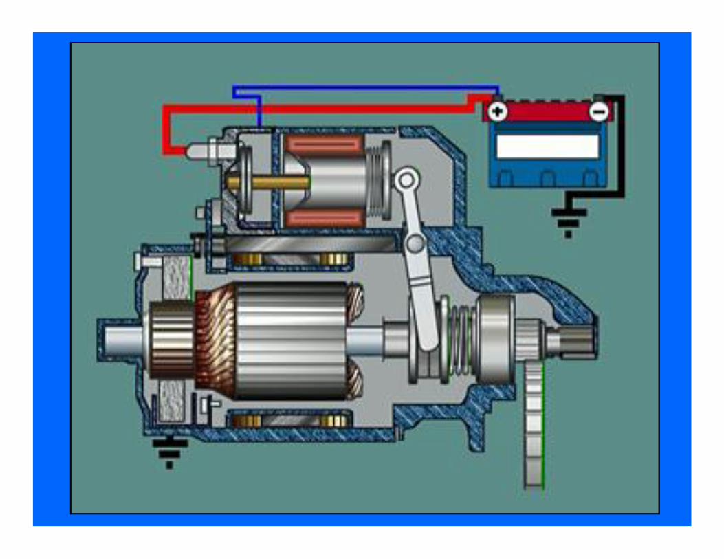
10. Starter Parts – Field Windings & Armature 11. Permanent Magnet Starters 14. Armature in any motor spins 15. Brushes in a Starter are Copper – Low Ω
Starting System Ch 18 Info to Know

Starting System Ch 18 Info to Know
Explain This!
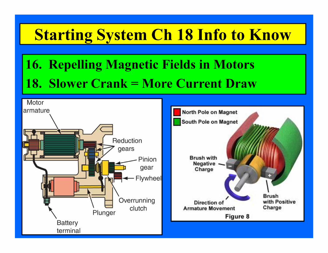
16. Repelling Magnetic Fields in Motors 18. Slower Crank = More Current Draw
Starting System Ch 18 Info to Know
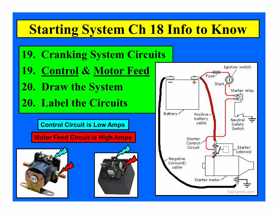
19. Cranking System Circuits 19. Control & Motor Feed 20. Draw the System 20. Label the Circuits
Starting System Ch 18 Info to Know
Control Circuit is Low Amps
Motor Feed Circuit is High Amps

20. Draw the System 20. Label the Circuits
Starting System Ch 18 Info to Know
M
Battery +
High Amps Motor Feed Circuit
Low Amps Control Circuit
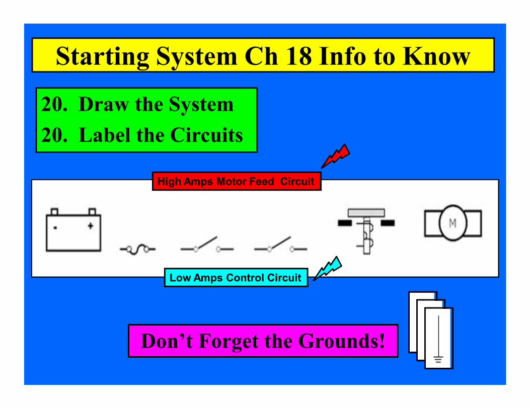
20. Draw the System 20. Label the Circuits
Starting System Ch 18 Info to Know
High Amps Motor Feed Circuit
Low Amps Control Circuit
Don’t Forget the Grounds!

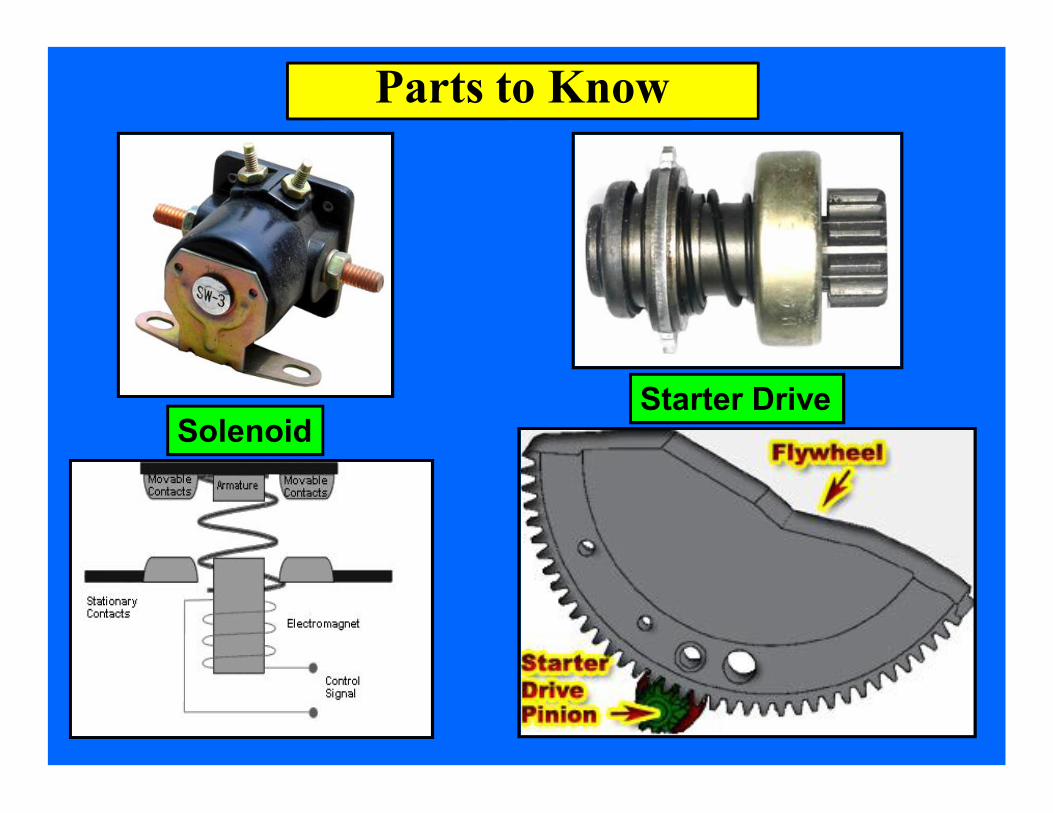
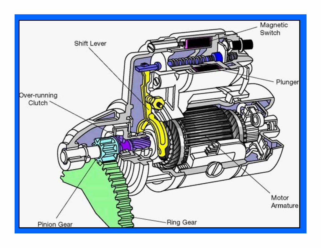
22. Solenoid Plunger vs. Relay Contacts (explain) 26. Starter Drive & Gear Ratio with Flywheel 27. Neutral Safety Switch in the Control Circuit
Starting System Ch 18 Info to Know

26. Starter Drive & Gear Ratio with Flywheel 27. Neutral Safety Switch
Starting System Ch 18 Info to Know
Starter Drive Overrunning Clutch
Clutch Switch
P/N
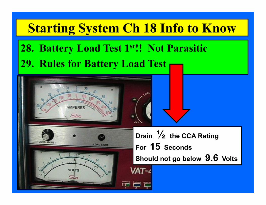
28. Battery Load Test 1 st !! Not Parasitic 29. Rules for Battery Load Test
Starting System Ch 18 Info to Know
Drain ½ the CCA Rating For 15 Seconds Should not go below 9.6 Volts
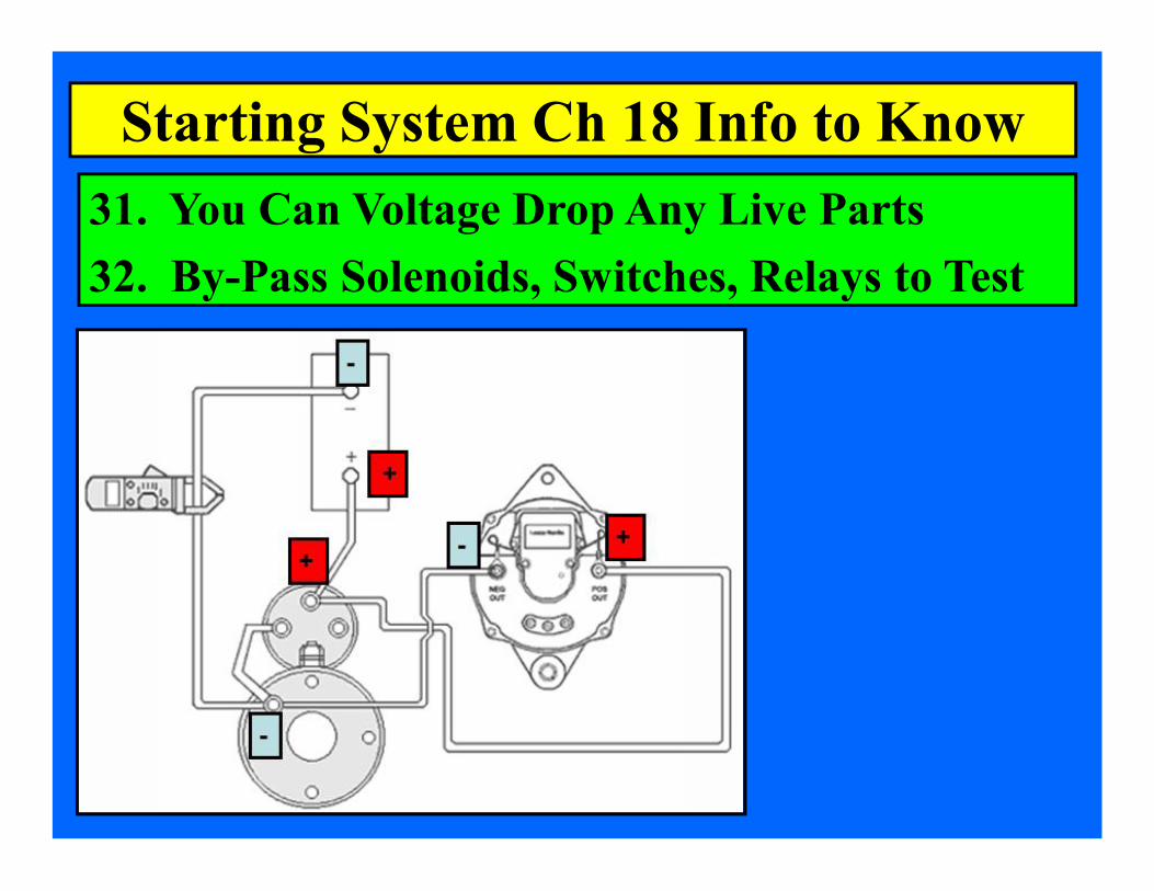
31. You Can Voltage Drop Any Live Parts 32. ByPass Solenoids, Switches, Relays to Test
Starting System Ch 18 Info to Know
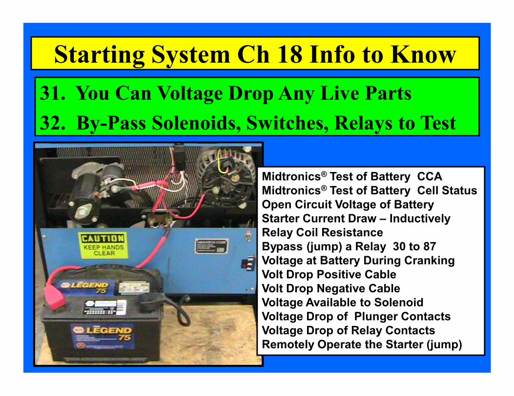
31. You Can Voltage Drop Any Live Parts 32. ByPass Solenoids, Switches, Relays to Test
Starting System Ch 18 Info to Know
Midtronics ® Test of Battery CCA Midtronics ® Test of Battery Cell Status Open Circuit Voltage of Battery Starter Current Draw – Inductively Relay Coil Resistance Bypass (jump) a Relay 30 to 87 Voltage at Battery During Cranking Volt Drop Positive Cable Volt Drop Negative Cable Voltage Available to Solenoid Voltage Drop of Plunger Contacts Voltage Drop of Relay Contacts Remotely Operate the Starter (jump)

34. Growler Test Results of an Armature 35. Starter Brushes Are Copper!!
Starting System Ch 18 Info to Know
Vibrating Strap indicates a shorted armature

Growler Test Indications
Starting System Ch 18 Info to Know Shorttohot armature metal strip vibrates
Open Armature no continuity to commutator bars
Shorttoground continuity to shaft

Sketch a Cranking System using schematic symbols
Cranking System Ch 18 Info to Know

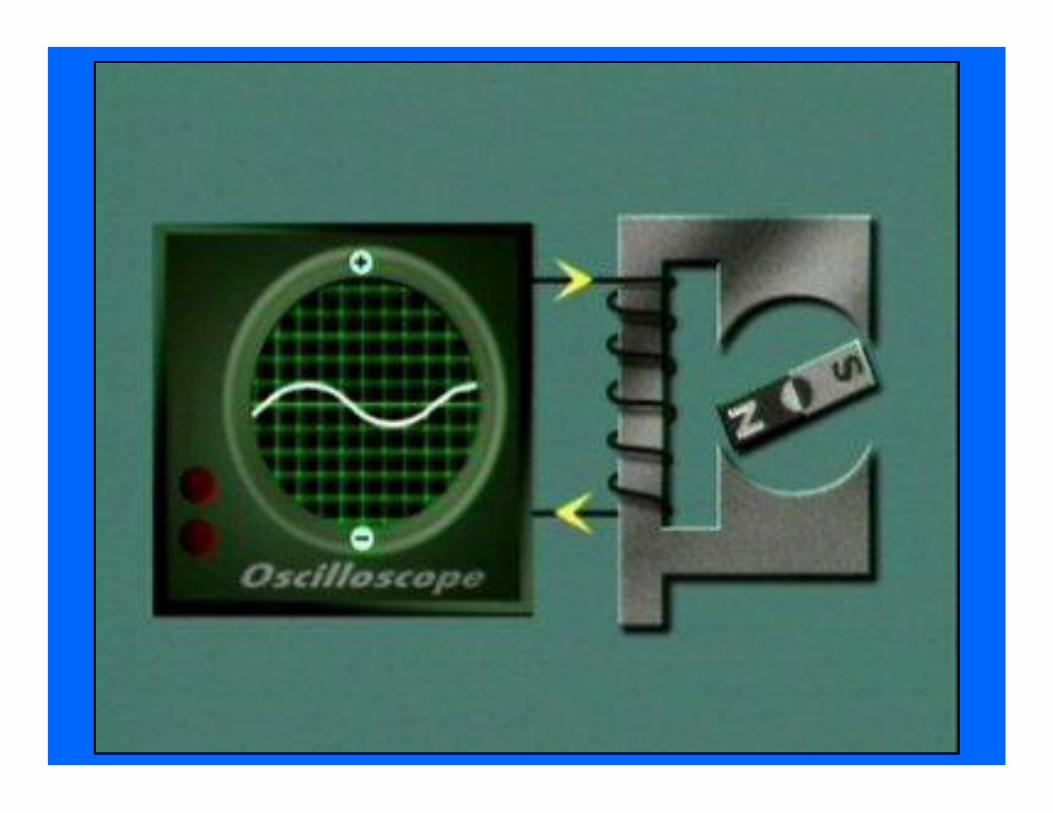
1. Purpose of the Charging System 2. Use of electromagnetism & induction 4. Moving Magnetism through Coils
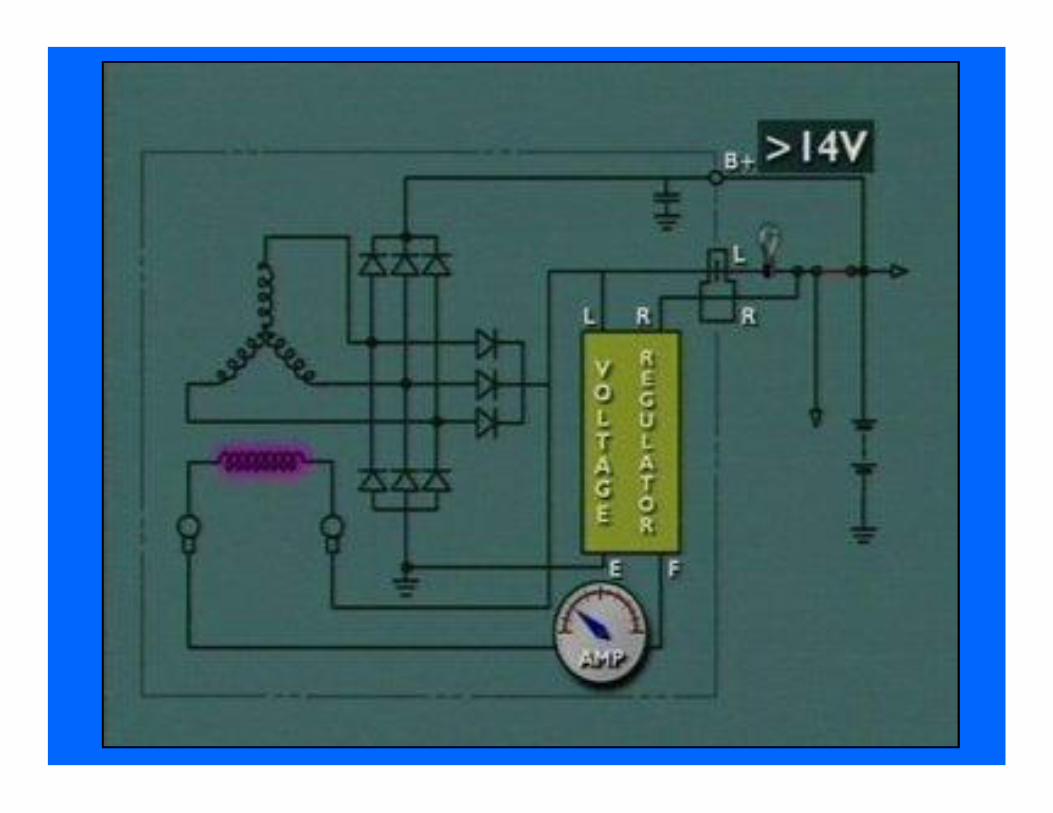
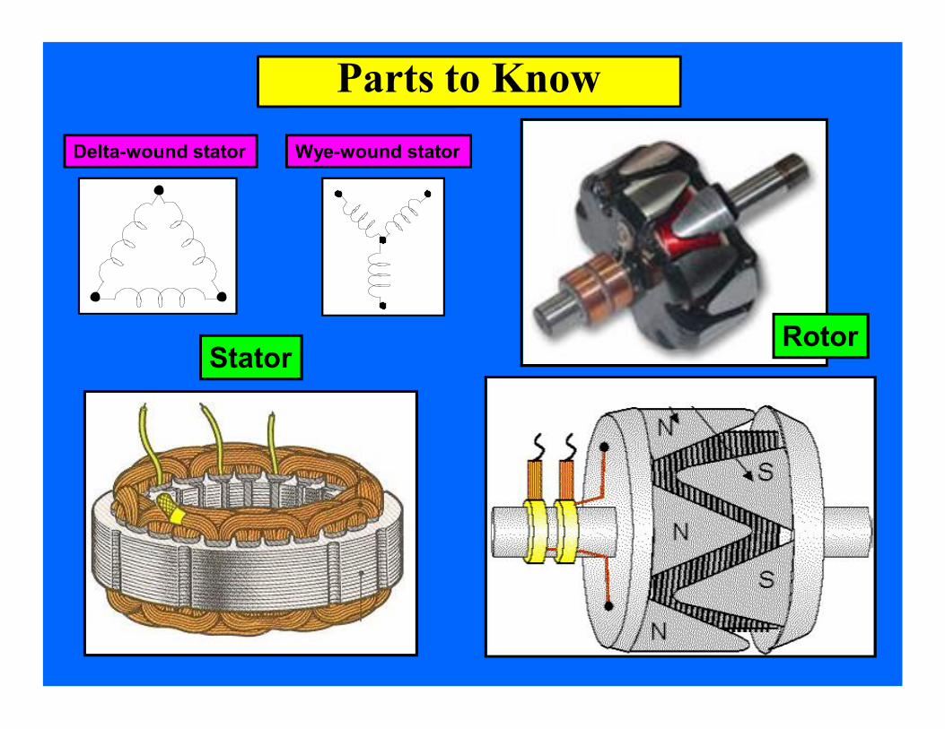
Rotor Field Coil & Stator Windings AC needs to be rectified to DC by diodes Copper Slip Rings & Carbon Brushes
Charging System Ch 19 Info to Know


8. Wyewound & Deltawound stators 12. Halfwave rectification 13. Fullwave rectification
Charging System Ch 19 Info to Know
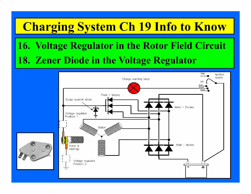
16. Voltage Regulator in the Rotor Field Circuit 18. Zener Diode in the Voltage Regulator
Charging System Ch 19 Info to Know
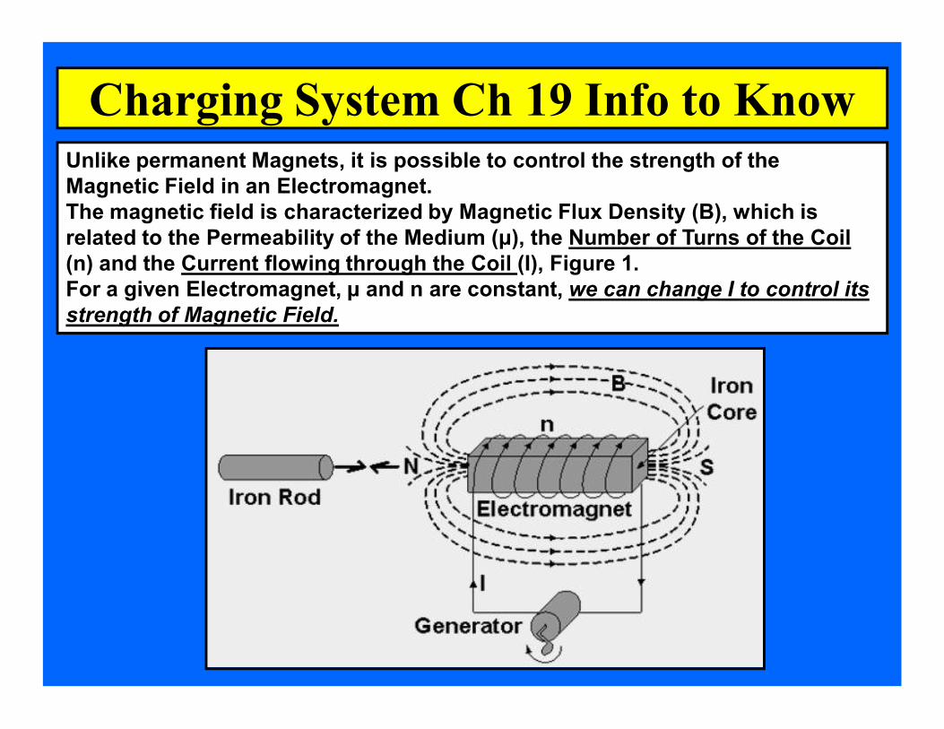
Charging System Ch 19 Info to Know Unlike permanent Magnets, it is possible to control the strength of the Magnetic Field in an Electromagnet. The magnetic field is characterized by Magnetic Flux Density (B), which is related to the Permeability of the Medium (μ), the Number of Turns of the Coil (n) and the Current flowing through the Coil (I), Figure 1. For a given Electromagnet, μ and n are constant, we can change I to control its strength of Magnetic Field.

21. Typical Charging Rate is Battery + 2 volts 26. Carbon Pile Rheostat in the VAT40 27. Full Field Test
Puts Full Battery Voltage into the Rotor Field Coil to Check Maximum Output
Charging System Ch 19 Info to Know

27. Full Field Test Puts Full Battery Voltage into the Rotor Field Coil to Check Maximum Output
Charging System Ch 19 Info to Know
PCM can replace the Voltage Regulator
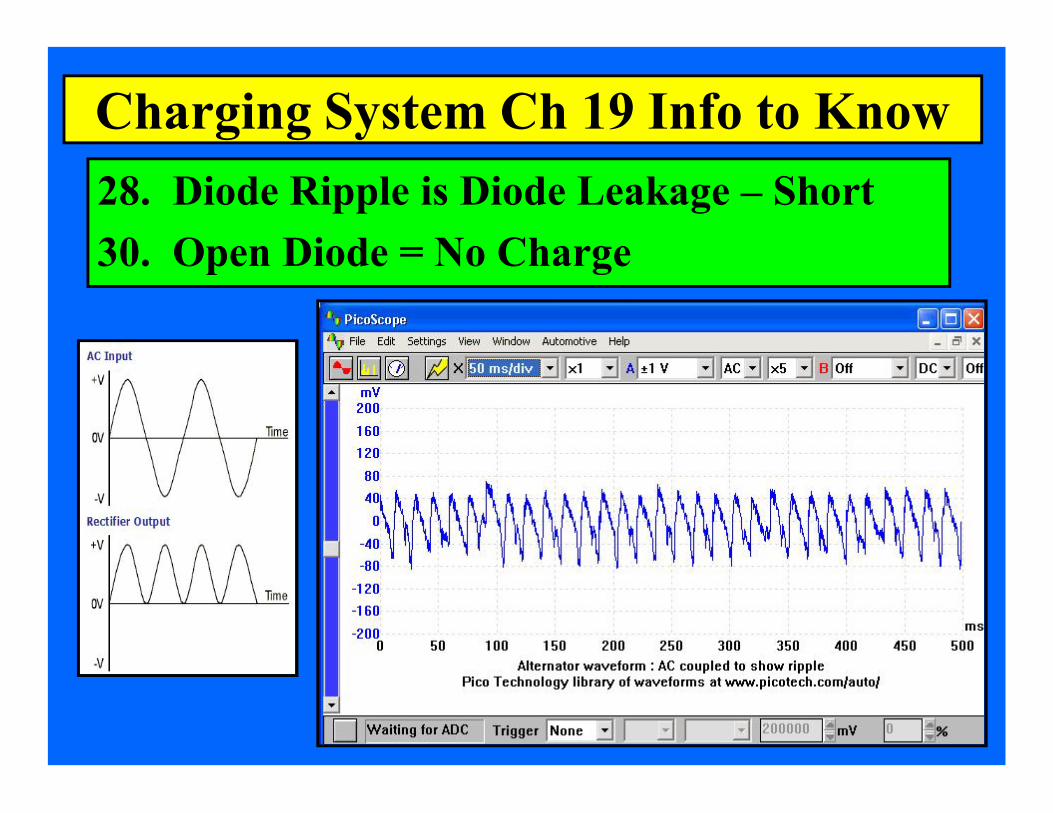
28. Diode Ripple is Diode Leakage – Short 30. Open Diode = No Charge
Charging System Ch 19 Info to Know
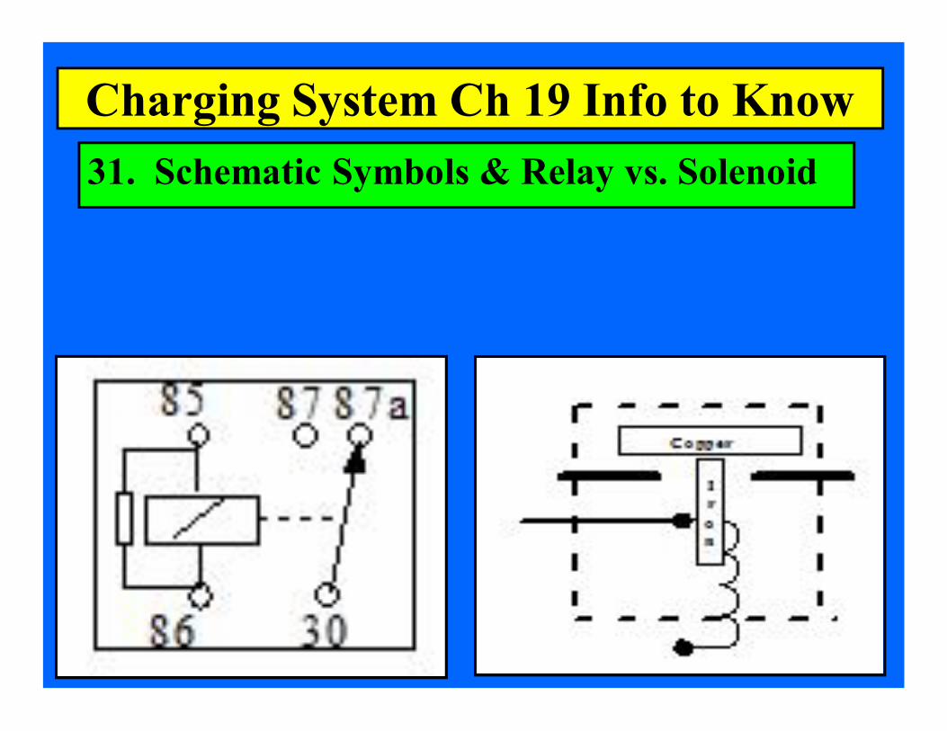
31. Schematic Symbols & Relay vs. Solenoid
Charging System Ch 19 Info to Know

Diode Testing with a DMM
Charging System Ch 19 Info to Know
Forward Biased Conducting with a .4 to .7 Voltage Drop
Reverse Biased Not Conducting
Reading OL on the DMM

Ohm’s Law Equations
Charging System Ch 19 Info to Know
V = A x O
A = V ÷ O
O = V ÷ A
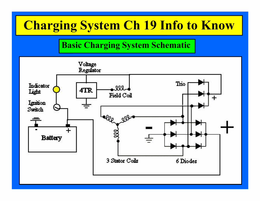
Charging System Ch 19 Info to Know Basic Charging System Schematic

Schematic Symbols
Thermistor Diode Zener Diode
WyeWound Stator DeltaWound Stator
Capacitor
TemperatureSensitive Variable Resistor

Schematic Symbols
Switch
Relay Solenoid
Solenoid Pullin Winding
Release Spring

Schematic Symbols
NPN Transistor PNP Transistor
Diode Trio Rectifier Bridge

Parts to Know
Diode Trio Rectifier Bridge
Parts to Know
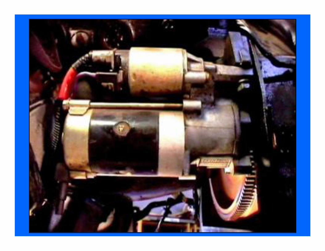
Solenoid Starter Drive
Parts to Know
Stator Rotor
Deltawound stator Wyewound stator


Starter Armature
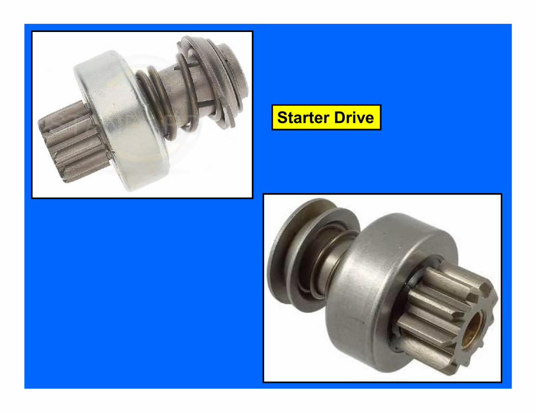
Starter Drive

Starter Bushings
Alternator Bearings
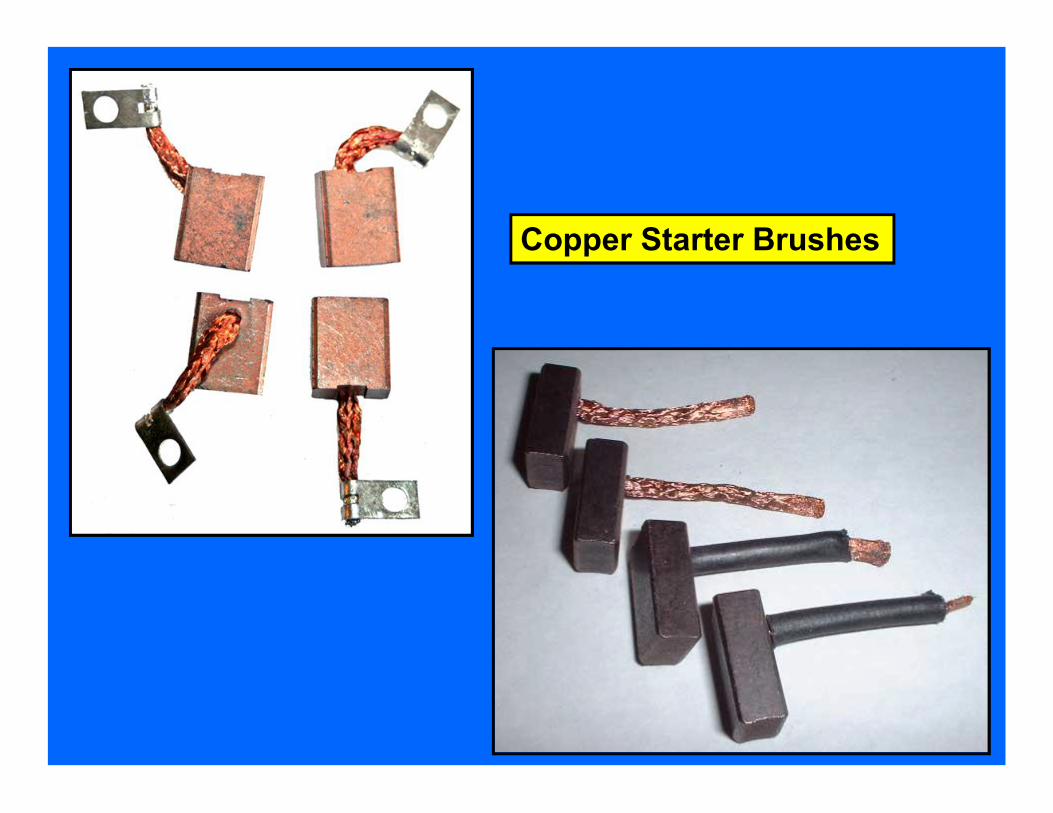
Copper Starter Brushes

Starter Field Coils
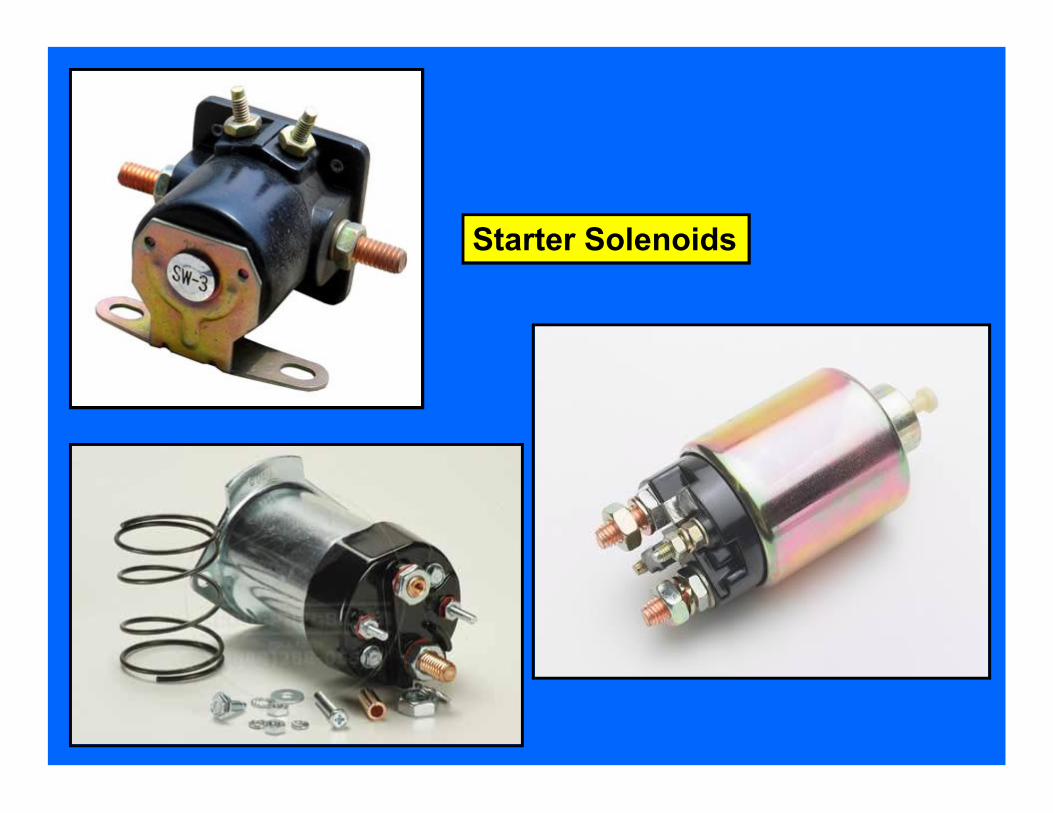
Starter Solenoids

Alternator Rotors

Alternator Stators

Carbon Alternator Brushes
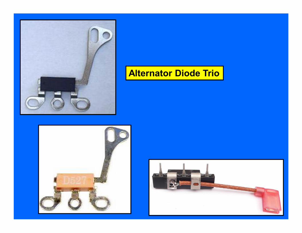
Alternator Diode Trio

Alternator Rectifier Bridge

Alternator Voltage Regulator

M
G
Motor
Generator
Relay Solenoid
Control Circuit that is Low Amps
Relays & Solenoids Both Have:
Load Circuit that is High Amps
Load can be motor, lights, etc.