auto tranny
TRANSCRIPT
21-I
TRANSMISSION MANUAL AND AUTOMATIC
CONTENTS r&?,AA-
AUTOMATIC TRANSMISSION ............ 57 GENERAL INFORMATION ........................... 57
SERVICE ADJUSTMENT PROCEDURES ..... 88 Propeller Shaft Oil Seals Replacement ...... 89 Speedometer Cable Replacement ............ 89 Throttle Cabel Check and Adjustment ....... 89 Transmission Fluid and Transfer Oil Changing and Inspection ........................... 88
SPECIAL TOOLS ........................................... 76 SPECIFICATIONS ......................................... 69
General Specifications ............................... 69 Lubricants .................................................. 75 Sealants and Adhesives ............ _______._ ____ -_. 75 Service Specifications ............................... 70 Torque Specifications ...... ..- ............. .._ ...... 74
TRANSMISSION AND TRANSFER ASSEMBLY ................................................... 95
TRANSMISSION CONTROL ........................ 90 TRANSMISSION OIL COOLER .................... 163
TROUBLESHOOTING ................................... 77 Converter Stall Test ................................. _. 84 Fluid Level and ATF Condition ................... 77 General ...................................................... 77 Governor Pressure Test .......................... ___ 84 Hydraulic Pressure Test ............................. 84 Inhibitor Switch .......................................... 78 Manual Linkage ......................................... 78 Overdrive Control System Circuit .............. 86 Road Test .................................................. 79 Selector Lever ..................................... ..-. ___ 78 Throttle Control Cable .............................. __ 78
MANUAL TRANSMISSION .................. 2 GEARSHIFT LEVER ASSEMBLY .................. 52
GENERAL INFORMATION ........................... 2
SERVICE ADJUSTMENT PROCEDURES ..... IO Propeller Shaft Oil Seals Replacement ...... II Speedometer Cable Replacement ............ 11 Transmission and Transfer Oil Changing and Inspection ........................................... IO
SPECIAL TOOLS ........................................... 8
SPECIFICATIONS ......................................... 3 General Specifications ............................... 3 Lubricants .................................................. 7 Sealants and Adhesives ............................. 7 Service Specifications ............................... 3 Torque Specifications ................................ 5
TRANSMISSION AND TRANSFER ASSEMBLY <2.6L ENGINE> ....................... 12
TRANSMISSION AND TRANSFER ASSEMBLY <3.OL ENGINE> ....................... 29
TROUBLESHOOTING ................................... 10 Gears slip out Noise, Vibration Oil is leaking Shifting gears is hard or troublesome
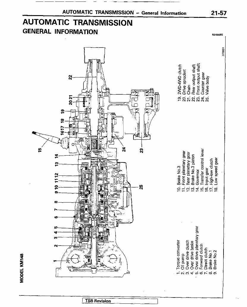
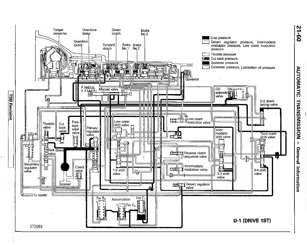
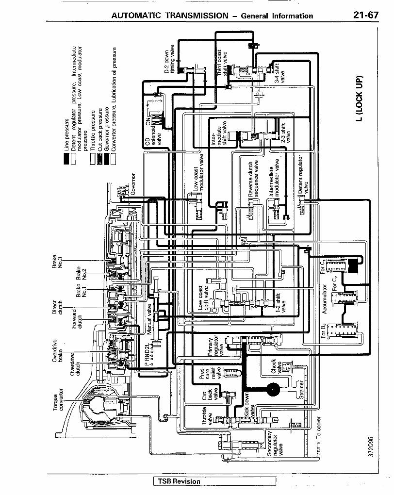
AUTOMATIC TRANSMISSION - General information
AUTOMATIC TRANSMISSION 21-57
GENERAL INFORMATION
1 TSB Revision

1 &/e%al~ clutch, 1
Direct i2.F
Brake Brake No.1 No.2
Throttle
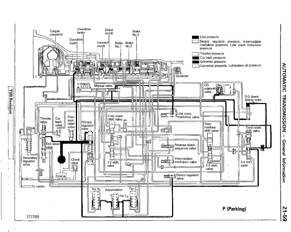
Line pressure F 0 Detent regulator pressure, Intermediate
mcduiator pressure, Low coast modulator 5 pressure ii
0 Thmttle pressure 1 Cut beck pressure 8 @ii
Governor pressure c=J Converter pressure, Lubrication oil pressure 5
P
OD solen vatve
D-2 down
&To cooler II’--------
372087
N (Neutral)
_ _ _ _ brake
!dIITbl clutch Brake
No.3 Overdrive clutch Forward Brake Brake
clutch No.1 Ny.2 I
m Line pressure 0 Detent regulator pressure. Intermediate
modulatolr pressure, Low coast modulator pressure
0 Throttle pressure m cut back pressure m Governor pressure a Converter pressure, Lubrication oil pressure
D2 down timing valve
Ill Low coast modulator II cut II Pres- I I I
Ilshift valve II II II shift v&n
11 Secondawlla 1111 1
To cooler
-=7 372088
P (Parking)
m Line pressure 0 Detent regulator pressure, Intermediate
modulator pressure, Low coast modutator pressure
0 Throttle pressure m Cut beck pressure
Governor pressure n Converter pressure, Lubrication oil DWWIIP
3gulaiol alve
modulator valve
D-l (DRIVE 1ST) 372089
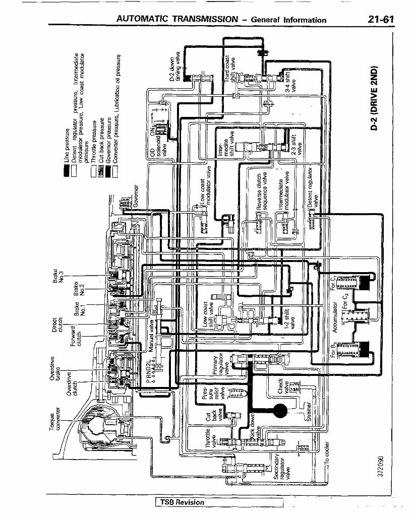
AUTOMATIC TRANSMISSION - General information 27-61
I’ ” -
I
) TSl3 Revision . .

21-62 AUTOMATIC TRANSMISSION - General Information
1 TSB Revision
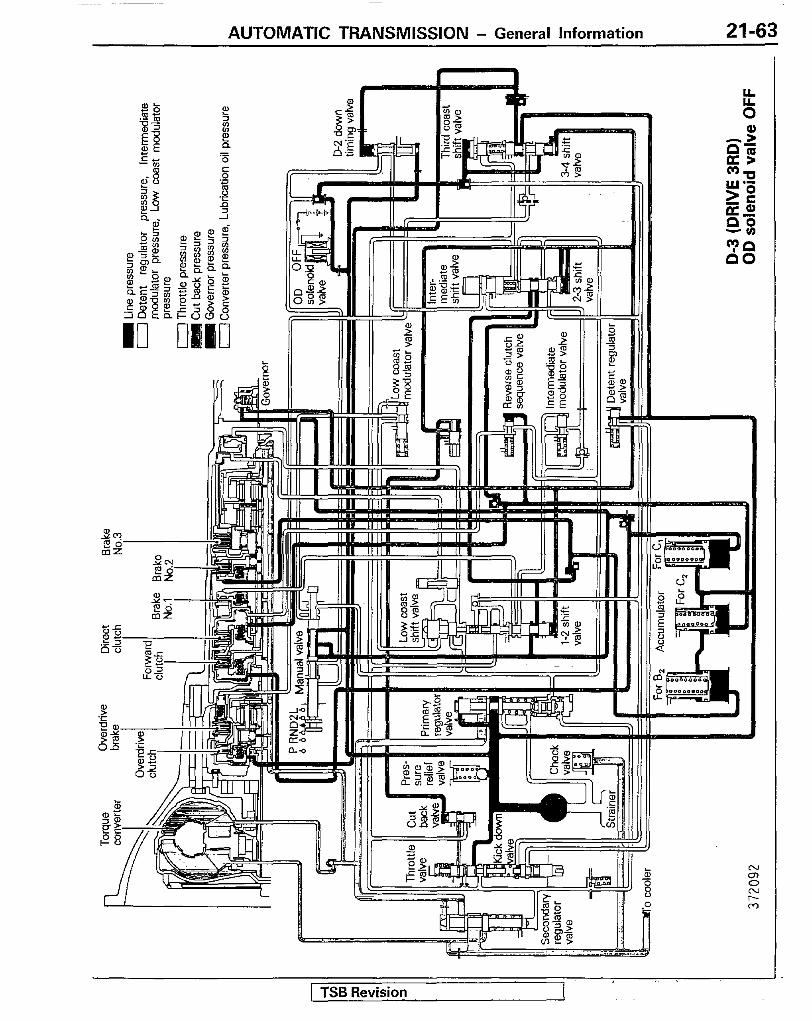
AUTOMATIC TRANSMISSION - General Information 21-63
( TSR Revision -

r Overdrive Direct cl*ftch
Brake Nq.3
To cooler 1+
rimary aulato he
m Line pressure 0 Detent regulator pressure, Intermediate
modulator pressure, Low coast mo4iulator pressure
0 Throttle pressure E&i Cut back pressure m Governor pressure 0 Converter pressure, Lubrication oil pressure
- Ii
#!J
Ii I
;e clutch we valve
D-2 down timing vatve
J D-4 (DRIVE 4TH) I

AUTOMATIC TRANSMISSION - General information 21-65
1 TSB Revision
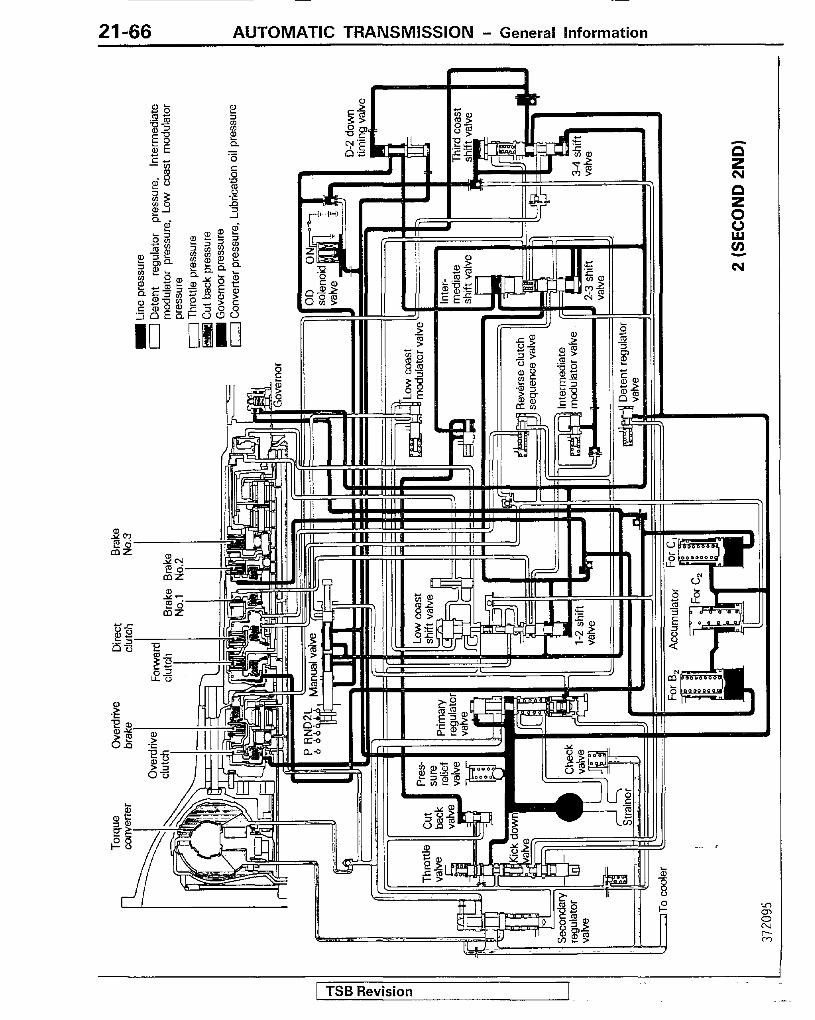
21-66 AUTOMATIC TRANSMISSION - General Information
TSB Revision
AUTOMATK TRANSMISSION - General information 21-67
ii -I-----
- - E
1 TSB Revision

--
21-68 AUTOMATIC TRANSMISSION - General information
TSB Revision
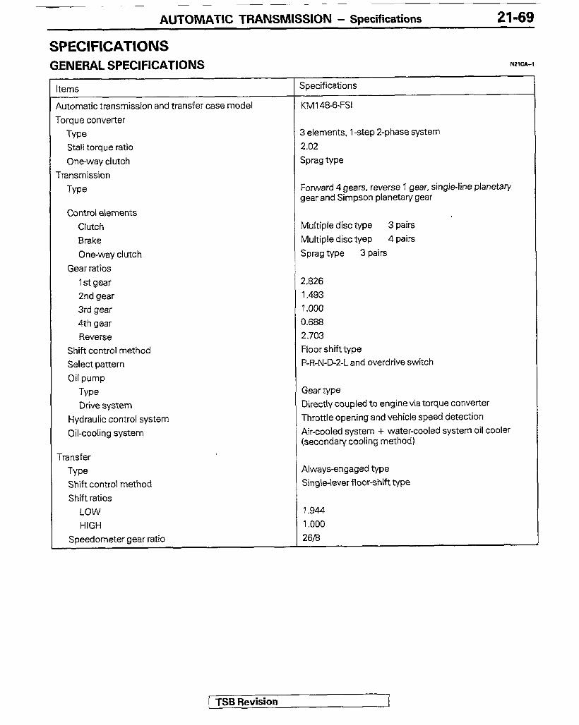
AUTOMATIC TRANSMISSION - Specifications 21-69
SPEClFlCATlONS GENERAL SPECIFICATIONS
terns
btomatic transmission and transfer case model -0rque converter
Type Stall torque ratio
One-way clutch
iransmission
Type
Control elements
Clutch
Brake One-way clutch
Gear ratios
1st gear
2nd gear 3rd gear 4th gear Reverse
Shift control method Select pattern
Oil pump
Type Drive system
Hydraulic control system
Oil-cooling system
Transfer
Type Shift control method Shift ratios
LOW HIGH
Speedometer gear ratio
Specifications
KM1 48-6-FSI
3 elements, 1 -step 2-phase system 2.02
$mg We
-orward 4 gears, reverse 1 gear, single-line planetary gear and Simpson planetary gear
blultiple disc type 3 pairs
Llultiple disc tyep 4 pairs
Swag tVpe 3 pairs
2.826 1.493 7.000 0.688 2.703 Floor shift type P-R-N-D-2-L and overdrive switch
Gear type Directly coupled to engine via torque converter Throttle opening and vehicle speed detection Air-cooled system + water-cooled system oil cooler (secondary cooling method)
Always-engaged type
Single-lever floor-shift type
1.944
1.000
2618
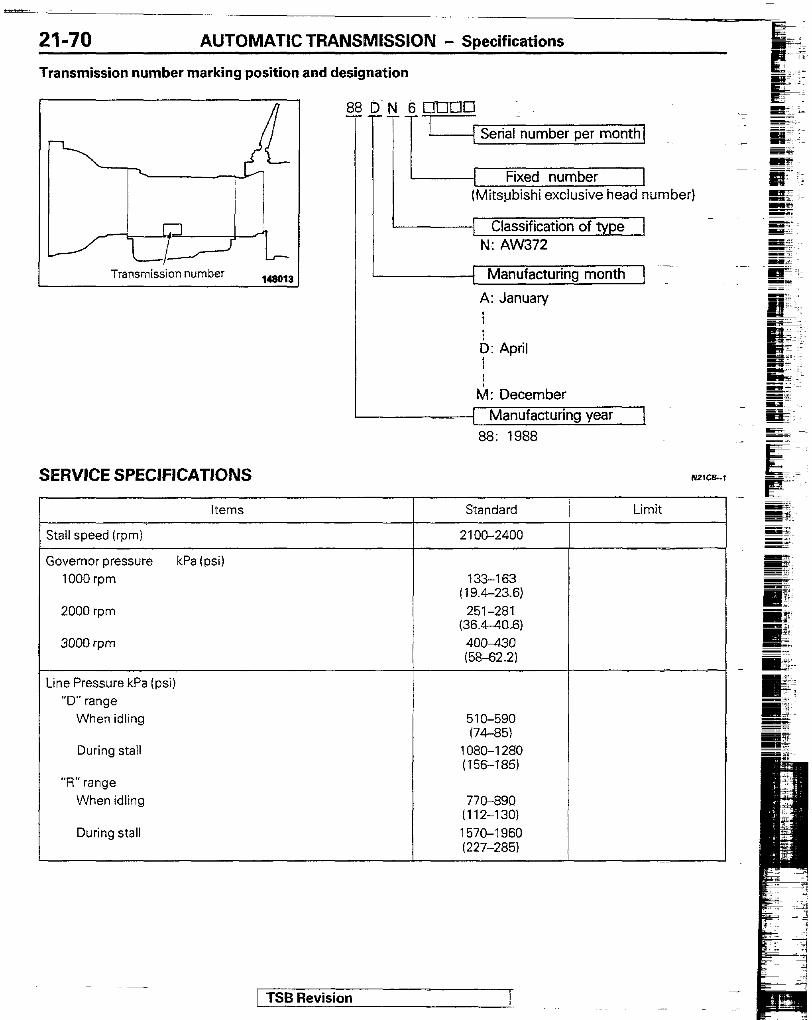
AUTOMATIC TRANSMISSION - Specifications
Transmission number marking position and designation
Transmission number
D N 6 q -IXI~
T-TT’ [ Serial number per month1
Fixed number (Mitsubishi exclusive head number)
1 Classification of type 1 N.: AW372
1 Manufacturing month ] -
A: January
P: April
M : December 1 Manufacturing year [ 88: 1988
SERVICE SPECIFICATIONS
Stall speed (rpm)
Sovernor pressure 1000 rpm
2000 rpm
3000 rpm
Items
kPa (psi)
- Standard
2100-2400
133-l 63 (19.4-23.6)
251-281 (36.4-40,6)
400-430 (58-62.2)
Limit
-ine Pressure kPa (psi) “D” range
When idling
During stall
“R” range When idling
During stall
510-590 (74-35)
1080-I 280 ( 156-I 85)
770-890 (112-130) 1570-I 960 (227-285)
/ TSB Revision

AUTOMATIC TRANSMISSION - Specifications 21-71
Items Standard Limit
1 Input shaft end play mm (in.) 0.3-0.9
(.012-.035)
Oil pump Side clearance mm (in.) 0.02-O-65
(.0008-.0020) (.004) Body clearance mm (in.) 0.07-0.15 0.3
(.0028-.0059) (012) Tip clearance (driven gear) mm (in.) 0.1 l-0.14 0.3
(.0043-.0055) (012)
Clutch and brake piston stroke mm (in.) Overdrive clutch(CO) I .56-2.53
(.0614-.0996) Forward clutch (C) 1.43-2.93
(.0563-.1154) Direct clutch (C2) 0.91-I .99
(.0358-.0783) No. 1 brake (B’) 0.80-I .73
(.0315-.0681) No. 2 brake (EP) 1 .Ol-2.25
(.0398-.0886)
Brake clearance mm (in.) Overdrive brake (B”)
No. 3 brake (B3)
0.65-2.21 (.0256-.0870)
0.61-2.64 (.0240-.I 039)
Transfer H-L clutch hub end play mm (in.)
input gear bearing end play mm (in.)
Input gear end play mm (in.)
O-O.08 (o-.003) O-0.06
(O-.002) O-0.06
(O-.002)
Transmission control Sleeve and selector lever clearance mm (in.) 15.2-l 5.9
(.60-.62)
1 TSB Revision
I . .
21-72 AUTOMATIC TRANSMlSSlON - Specifications
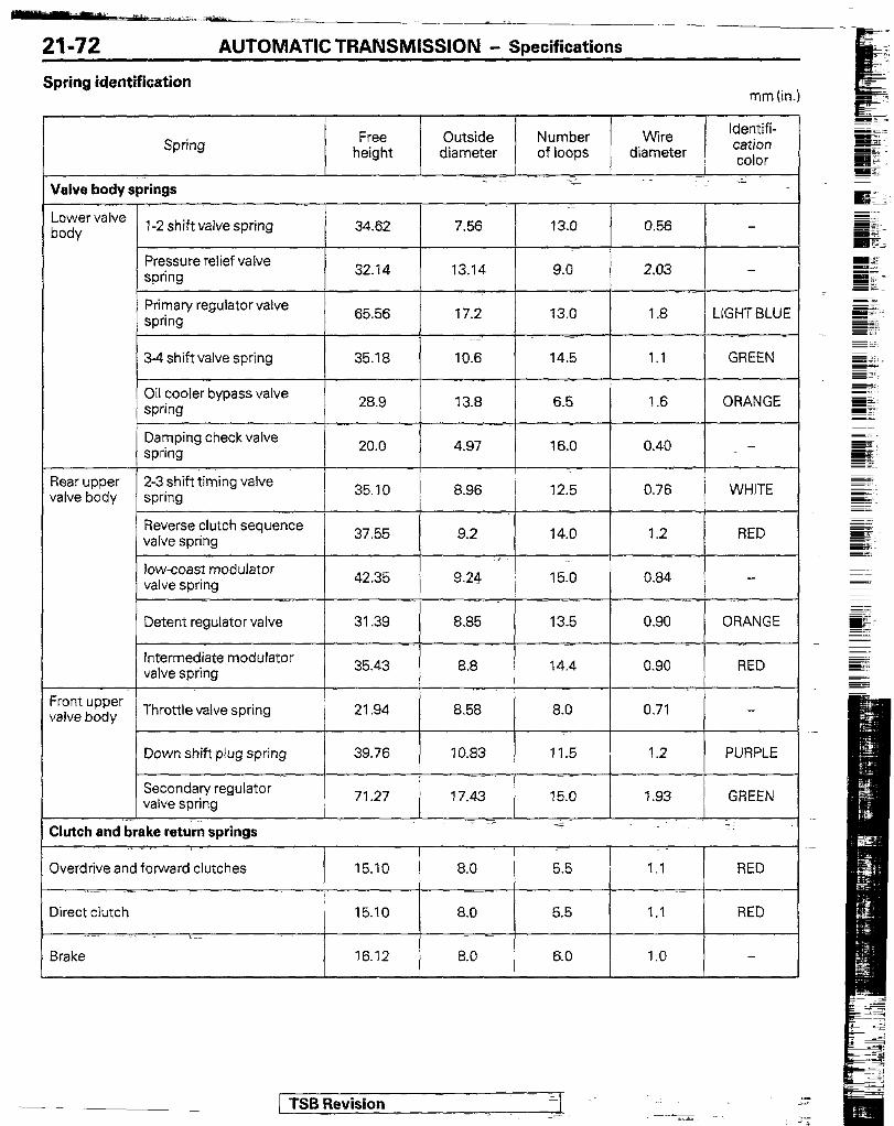
Spring identification mm (in.)
Spring
Valve body springs
-ower valve oody 1-2 shift valve spring
Pressure-relief valve spring
Primary regulator valve spring
3-4 shift valve spring
Oil cooler bypass valve spring
Damping check valve spring
3ear upper 2-3 shift timing valve /alve body spring
Reverse clutch sequence valve spring
low-coast modulator valve spring
Detent regulator valve
Intermediate modulator valve spring
?ont upper /alve body Throttle valve spring
Down shift plug spring
Secondary regulator valve spring
Xtch and brake return springs
Overdrive and forward clutches
Iirect clutch
3rake
Free Outside Number Wire Identifi-
height diameter of loops diameter cation color
34.52 7.56 13.0 0.56
32.14 13.14 9.0- 2.03
65.56 17.2 '13.0 1 .a LIGHT BLUE
35.18 10.6 145 1.1 GREEN
28.9 13.8 6.5 1.6 ORANGE
20.0 4.97 16.0 0.40 .-
35.10 8.96 12.5 0.76 WHITE
37.55 9.2 14.0 1.2 RED
42.35 9.24 15.0 0.84
31.39 8.85 13.5 0.90 ORANGE
35.43 8.8 14.4 0.90 RED - ._-
21.94 8.58 8.0 0.71 7
39.76 10.83 11.5 1.2 PURPLE
71.27 17.43 15.0 1.93 GREEN .~~ -.
- -- 15.10 8.0 5.5 1.1 RED
-
15.10 8.0 5.5 1.1 RED
16.12 8.0 6.0 1.0
1 TSB Revision --
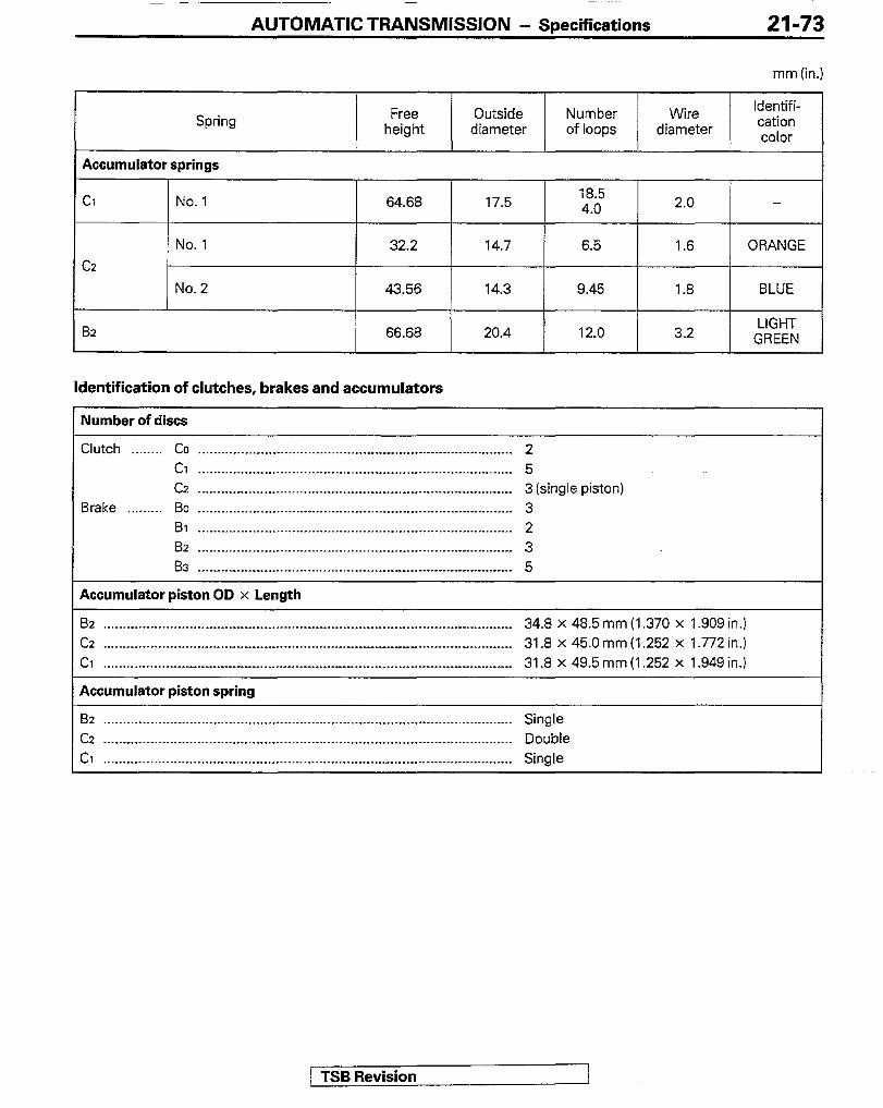
AUTOMATIC TRANSMISSION - Specifications 21-73
mm (in.)
Spring Free height
Outside diameter
Number of loops
Wire diameter
Identifi- cation color
Accumulator springs -1 Cl
C2
a2
r f
No. 1 64.68 17.5 18.5 4.0
2.0 -
No. 1 32.2 14.7 6.5 1.6 ORANGE
No. 2 43.56 14.3 9.45 1.8 BLUE
/ 66.68 20.4 12.0 3.2
LIGHT GREEN
Identification of clutches, brakes and accumulators
Number of discs
Clutch __...... Co . . . . . ..__.._ _.___ .____ _ _..__..______._ ________ ________ ___._____ .___ _ ____._._____ 2 Cl . . . . . . . . . . . . . . . . . . . . . . . . . . . . . . . . . . . . _...__..._..._.._.__..~ -.... _ .--._ _._ ..-. __. 5 Cz . .._.....__...................... ________ ___.__. _..__-__.._ .__. _______.__ __._ _ 3 (single piston)
Brake .._...... Bo __..__...__.__.. _ _.___._...__.__..__....... _______ _.__..__.__._..___._.......... 3 Bl . . . . . .._. _ . . .._.._._. _ .___.__________..._........ _ .___.. _ _.__.__._ _ ___._...__.._ 2 Bz . . . .._.......__._ __ _______._ ____.___ _.__ _ .__..._. _ .____..__ _ .._...__.._._.._.__. 3 8s ._..I.__._.._ ______.__ .__.___..__..__...._~...~.~ ___ __.____ _ ____._ _ ..__...I_._ _ 5
Accumulator piston OD x Length
Bz . . . . .._.. _ . . . . . . . . . . . . ..___ __________ ._.__.,........._._.............. _ ._.............._._........ __.__ 34.8 x 48.5 mm (1.370 x 1 SOS in.) cz . . . . . . . . . . _ . . . . . . . . . . . . . . . . . . . . . . _ . . . . _.._..._..__ . . . . . . . . . . . . _ . ..-. __.___ _-.-.-_..-.- _ . .._..... _ 31.8 x 45.0 mm (1.252 x 1.772 in.) Cl . . . . . . . . . . . . . . . . _.__.-___ _____ ______ _......._... ____________._ .._____....._......... ___________._____ 31.8 x 49.5 mm (1.252 x 1.949 in.)
Accumulator piston spring
82 . . . . . .._.. _ _..__._ _ _.__..._... ______ . . . . _ __.__.._...._.._..._.. _ . . . . . . . ..-.. _ . .._._..._..._.._._...... Single Cz __.___-_._ _.____._ _____..______.__._._........................ __.____________.___ _~_______ _ . ..__..._._ Double Ci . . . . . . . . . . . . . . . . . . . . . . . _ .._._.____ _ __..__....................~.. ______..__ .__._...... _ . . . . . . . . . . . . . . . .._ Single
1 TSB Revision
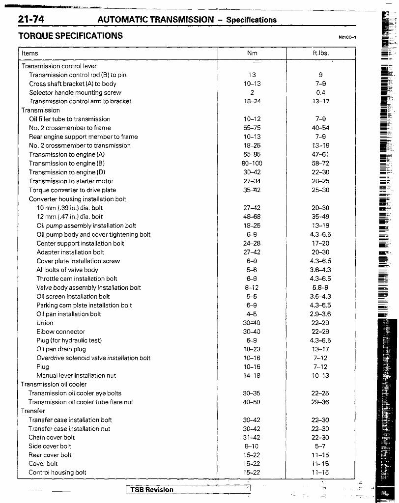
21-74 AUTOMATIC TRANSMISSION - Specifications
TORQUE SPECIFICATIONS
Items
Transmission control lever Transmission control rod (6) to pin Cross shaft bracket (A) to body Selector handle mounting screw Transmission control arm to bracket
Transmission Oil filler tube to transmission No. 2 crossmember to frame Rear engine support member to frame No. 2 crossmemberto transmission Transmission to engine (A) Transmission to engine(B) Transmission to engine ID) Transmission to starter motor Torque converter to drive plate Converter housing installation bolt
IO mm (.39 in.) dia. bolt 12 mm j.47 in.) dia. bolt Oil pump assembly installation bolt Oil pump body and cover-tightening bolt Center support installation bolt Adapter installation bolt Cover plate installation screw All bolts of valve body Throttle cam installation bolt Valve body assembly installation bolt Oil screen installation bolt Parking cam plate installation bolt Oil pan installation bolt Union Elbow connector Plug (for hydraulic test) Oil pan drain plug Overdrive solenoid valve installation bolt Plug Manual lever installation nut
Transmission oil cooler Transmission oil cooler eye bolts Transmission oil cooler tube flare nut
Transfer Transfer case installation bolt Transfer case installation nut Chain cover bolt Side cover bolt Rear cover bolt Cover bolt Control housing bolt
Nm ft.lbs.
13 9 IO-13 7-9
2 0.4 18-24 13-17
IO-12 7-Q 55-75 40-54 IO-13 7-Q 18-25 13-18 65;85 47-61 80-l 00 58-72 30-42 22-30 27-34 20-25 36-712 25-30
2742 20-30 48-68 3549 18-25 13-18 6-9 4.3-6.5
24-28 17-20 27-42 20-30
6-9 4.3-6.5 5-6 3X-4.3 6-9 4.3-6.5
8-12 5.8-9 5% 3.6-4.3 6-9 4.3-6.5 4-5 2.9-3.6
30=40 22-29 30-40 22-29
6-9 4.3-6.5 18-23 13-17 JO-16 7-12 IO-16 7-12 14-18 IO-13
30-35 22-25 40-50 29-36
30-42 30-42 31-42 6-10 15-22 15-22 15-22 ~:
22-30 2230 2230
5-J 11-15 II-15 1 I-15
.._ +
-. [ TSB Revision
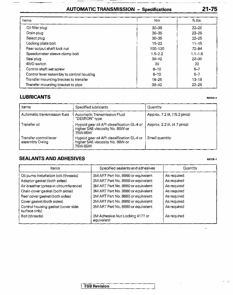
AUTOMATIC TRANSMISSION - Snecifications 21-75
terns Nm ftlbs.
Oil filler plug 3035 22-25 Drain plug 3035 22-25 Select plug 30-35 22-25 Locking plate bolt 15-22 11-15 Rear output shaft lock nut 100-l 30 72-84 Speedometer sleeve clamp bolt 1.5-2.2 1.1-1.6 Seal plug 30-42 22-30 4WD switch 30 22 Control shaft set screw 8-10 5-7 Control lever assembly to control housing 8-10 5-7 Transfer mounting bracket to transfer 18-25 13-18 Transfer mounting bracket to pipe 30-42 22-29
LUBRICANTS NZlMI
Items Specified lubricants Quantity
Automatic transmission fluid
Transfer oil
Transfer control lever assembly O-ring
AutomaticTransmission Fluid “DEXRON” type
Hypoid gear oil API classification GL-4 or higher SAE viscosity No. 80W or 75w-85w Hypoid gear oil API classification GL-4 or higher SAE viscosity No. 80W or 75w-85w
Approx. 7.2 lit. (15.2 pints)
Approx. 2.2 lit. (4.7 pints)
Small quantity
SEALANTS AND ADHESIVES ?421cE-l
items
Oil pump installation bolt(threads) Adaptor gasket (both sides) Air breather (press-in circumference) Chain cover gasket (both sides) Rear cover gasket (both sides) Cover gasket (both sides) Control housing gasket (cover side surface only) Bolt (threads)
Specified sealants and adhesives
3M ART Part No. 8660 or equivalent 3M ART Part No. 8660 or equivalent 3M ART Part No. 8660 or equivalent 3M ART Part No. 8660 or equivalent 3M ART Part No. 8660 or equivalent 3M ART Part No. 8660 or equivalent 3M ART Part No. 8660 or equivalent
3M Adhesive Nut Locking 4171 or equivalent
Quantih/
As required As required As required As required As required As required As required
As required
TSB Revision

21-76 AUTOMATIC TRANSMISSION - Soecial Tools
SPECIAL TOOLS
MD998412 ~. Guide : Installation of oil pump -.
MD99821 7 Gauge T x Check of quality of assembly condiG&
/
MB998903 -~ Spring compres& Disassembly and assembly of clutch and brake
/ TSB Revision e -:
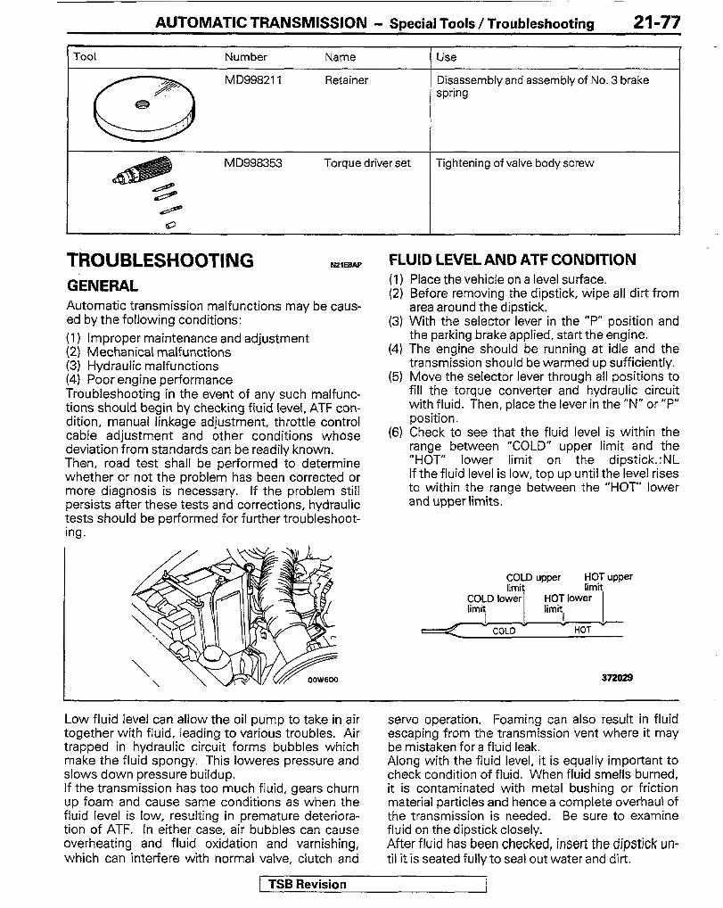
AUTOMATIC TRANSMISSION - Special Tools / Troubleshooting 21-77
Tool Number Name Use
*/,
a
MD99821 1 Retainer Disassembly and assembly of No. 3 brake spring
e
MD998353 Torque driver set Tightening of valve body screw
/ 8
TROUBLESHOOTING GENERAL Automatic transmission malfunctions may be caus- ed by the following conditions: (I) Improper maintenance and adjustment (2) Mechanical malfunctions (3) Hydraulic malfunctions (4) Poor engine performance Troubleshooting in the event of any such malfunc- tions should begin by checking fluid level, ATF con- dition, manual linkage adjustment, throttle control cable adjustment and other conditions whose deviation from standards can be readily known. Then, road test shall be performed to determine whether or not the problem has been corrected or more diagnosis is necessary. If the problem still persists after these tests and corrections, hydraulic tests should be performed for further troubleshoot- ing.
AZEBAP FLUID LEVEL AND ATF CONDITION (1) Place the vehicle on a level surface. (2) Before removing the dipstick, wipe all dirt from
area around the dipstick. (3) With the selector lever in the “P” position and
the parking brake applied, start the engine. (4) The engine should be running at idle and the
transmission should be warmed up sufficiently. (5) Move the selector lever through all positions to
fill the torque converter and hydraulic circuit with fluid. Then, place the lever in the”N” or “P” position.
(6) Check to see that the fluid level is within the range between “COLD” upper limit and the “HOT” lower limit on the dipstick.:NL If the fluid level is low, top up until the level rises to within the range between the “HOT” lower and upper limits.
1 J ! !. COLD HOT
37202s
Low fluid level can allow the oil pump to take in air together with fluid, leading to various troubles. Air trapped in hydraulic circuit forms bubbles which make the fluid spongy. This loweres pressure and slows down pressure buildup. If the transmission has too much fluid, gears churn up foam and cause same conditions as when the fluid level is low, resulting in premature deteriora- tion of ATF. In either case, air bubbles can cause overheating and fluid oxidation and varnishing, which can interfere with normal valve, clutch and
servo operation. Foaming can also result in fluid escaping from the transmission vent where it may be mistaken for a fluid leak. Along with the fluid level, it is equally important to check condition of fluid. When fluid smells burned, it is contaminated with metal bushing or friction material particles and hence a complete overhaul of the transmission is needed. Be sure to examine fluid on the dipstick closely. After fluid has been checked, insert the dipstick un- til it is seated fully to seal out water and dirt.
TSB Revision I
21-78
“F
AUTOMATIC TRANSMISSION - Troubleshooting
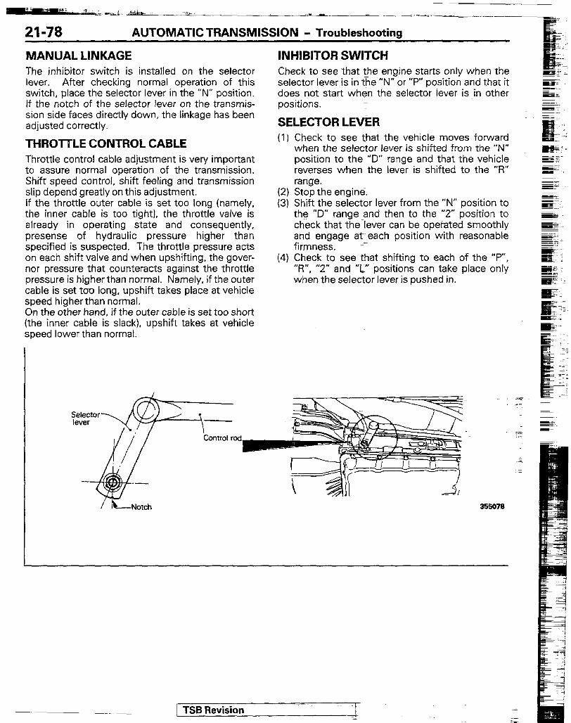
MANUAL LINKAGE The inhibitor switch is installed on the selector lever. After checking normal operation of this switch, place the selector lever in the “N” position. If the notch of the selector lever on the transmis- sion side faces directly down, the linkage has been adjusted correctly.
THROTTLE CONTROL CABLE Throttle control cable adjustment is very important to assure normal operation of the transmission. Shift speed control, shift feeling and transmission slip depend greatly on this adjustment. If the throttle outer cable is set too long (namely. the inner cable is too tight], the throttle valve is already in operating state and consequently, presense of hydraulic pressure higher than specified is suspected. The throttle pressure acts on each shift valve and when upshifting, the gover- nor pressure that counteracts against the throttle pressure is higher than normal. Namely, if the outer cable is set too long, upshift takes place at vehicle speed higherthan normal. On the other hand, if the outer cable is set too short (the inner cable is slack), upshift takes at vehicle speed lower than normal.
INHIBITOR SWITCH Check to see that the engine starts only when the selector lever is in the “N” or “P” position and that it does not start when the selector lever is in other positions.
SELECTOR LEVER (1) Check to see that the vehicle moves forward
when the selector lever is shifted from the “N” position to the “D” range and that the vehicle reverses when the lever is shifted to the ‘5” range.
(2) Stop the engine. (3) Shift the selector lever from the “N” position to
the “D” range and then to the “2” position to check that the Tever can be operated smoothly and engage at each position with reasonable firmness. L
(4) Check to see that shifting to each of the “P”, “R”, “2” and “L” positions can take place only when the selector lever is pushed in.
[ TSB Revision

AUTOMATIC TRANSMISSION - Troubleshooting 21-79
ROAD TEST Prior to performing road test, be sure to make basic checks including check and adjustment of fluid level and condition and adjustment of the throttle cable. For road test, the transfer must be placed in the 2H (2WD-high) position. In road test, various changes such as slips in transmission and shifting conditions are checked and hence the transmission operation at each shift position must have been checked.
D RANGE TEST
Start with throttle valve opened (50% and full), and check upshift from l-speed + Z-speed, Z-speed -. 3-speed and 3-speed + 4-speed. Check that speed change points match shift pattern. (Refer to P.21-83.)
1
Will not upshift, 1 -speed -P-speed
1
Will not upshift, 2-speed +3-speed
1 1 Will not upshift, 3-speed-4speed (with throttle Speed change
valve opening under 85%) points incorrect
l Governor malfunction
l l-2 shift valve malfunction
at 2-speed, 3-speed and 4-speed. Check that possible kickdown vehicle speed limit at 2- speed - l-speed, 3-speed -) l-speed, 3-speed -+ 2speed,
- l-speed, Cspeed - 2-speed. 4-speed -) 3- speed conforms with the shift pattern, (Refer to P.2183.)
l Incorrect throttle cable adiustment
1 TSB Revision

AUTOMATIC TRANSMlSSlON - Troubleshooting
When traveling in 3-speed or 4-speed, release accelerator and shift to L. Check that 3-speed - Z-speed or 4-speed - 3-speed takes place immediately and Z-speed - l-speed dowsnshift conforms with shift pattern. (Refer to P.21;83.)
When traveling in 3-speed or 4-speed, shift to 2 and L and check engine brake function in each range.
\ / .- -- EE
Check for abnormal noise(s) during acceleration and deceleration. Check for shocks when slipping and chang- ing speed.
I
o Accumulator malfunction
1 TSB Revision :

AUTOMATIC TRANSMISSION - Troubleshootina 21-81
Check for abnormal noise(s) or vibration when traveling in B-speed or 4-speed.
Strong abnormal noise and vibration
Incorrect torque converter installation
a Speed change gear wheel not meshing correctly l Incorrect drive plate installation
NOTE Abnormal noises and vibrations are often caused by an unbalanced propeller shaft, differential, tire, torque converter, engine etc. Extremely thorough inspection is therefore required.
Check that lock up ON, OFF and speed change point con- forms with shift pattern.
NOTE (1) Determine the moment when lock up turns ON by decreased engine rpm or by a slight shock back and forth. (2) Determine the moment when lock up turns OFF by increased engine rpm. (3) Check lock up condition by pumping the accelerator slightly. If en
opening size, determine that the lock up is OFF, if not, determine It 43 ine rpm rises in accordance with throttle valve N.
I
When lock up is OFF, drive power is transferred throu h the fluid in the torque converter and therefore, when the accelerator pedal is depressed, slipping occurs inside t e torque converter with a resulting large increase in engine 7l rpm. I
[ TSB Revision

21-82 AUTOMATIC TRANSMISSION - Troubleshooting
2 RANGE TEST
Start with throttle valve openrng at 50% and full. Check that
-- -
I I 1
Kickdown and check that possible kickdown vehicle speed - l-speed conforms with shift pattern.
Will not downshift or icorrect speed change point.
I
o Detent regulator pressure malfunction l Governor malfunction l Misadjusted throttle cable l 1-Z shift valve malfunction l Line pressure malfunction
L RANGE TEST
Check that it dose not upshift to Z-speed
I -
Upshifts
I
Low coast modulator valve malfunction
-7
-
.-:
[ TSB Revision
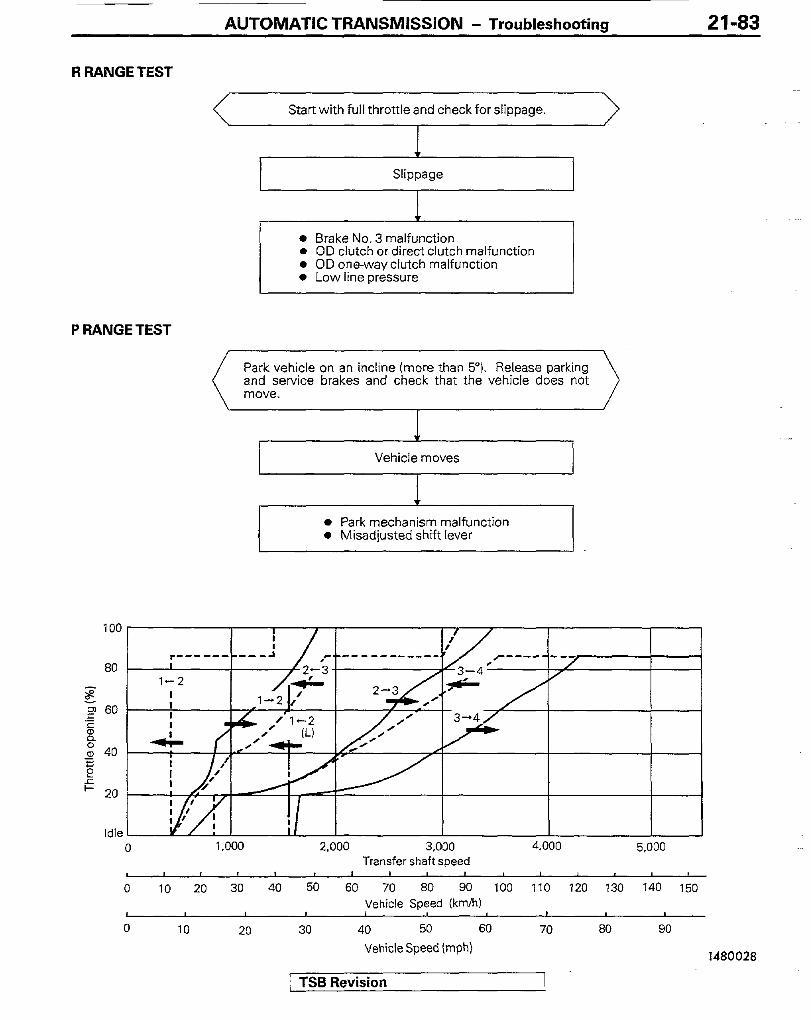
AUTOMATIC TRANSMISSION - Troubleshooting 21-83
R RANGE TEST
Start with full throttle and check for slippage.
l Brake No. 3 malfunction l OD clutch or direct clutch malfunction l OD one-way clutch malfunction 0 Low line pressure
P RANGE TEST
Park vehicle on an incline (more than 5”). Release parking and service brakes and check that the vehicle does not
Vehicle moves
I I
l Park mechanism malfunction l Misadjusted shift lever
80 -I,’ 1-2
P g .z 60
s z a, 40
E e
c 20
100
Idle 0 1,000 2.000 3,000 4.000 5.000
Transfer shaft speed
0 10 20 30 40 50 60 70 60 90 100 110 120 130 140 150 Vehicle Speed (km/h)
I / 0 IO 20 30 40 50 60 70 80 90
Vehicle Speed (mph) 1480028
/ TSB Revision 1
21-84 AUTOMATK TRANSMISSION - Troubleshooting
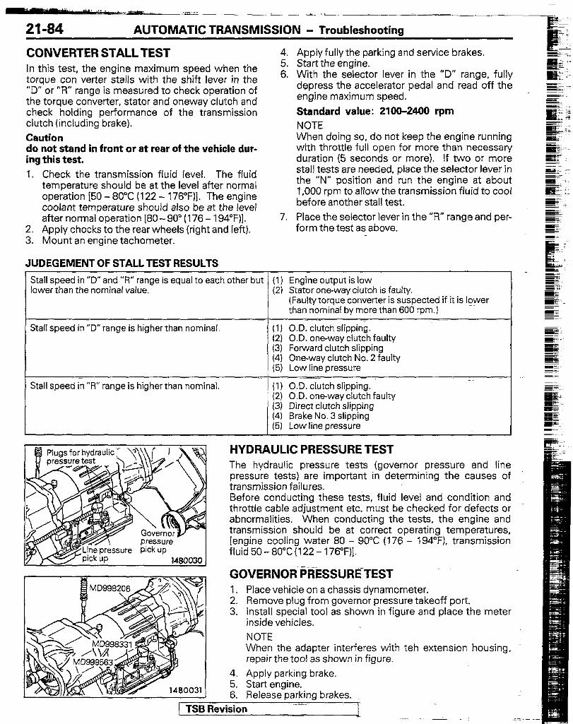
CONVERTER STALL TEST In this test, the engine maximum speed when the torque con verter stalls with the shift lever in the ‘ID” or “R” range is measured to check operation of the torque converter, stator and oneway clutch and check holding performance of the transmission clutch (including brake). Caution do not stand in front or at rear of the vehicle dur- ing this test. 1. Check the transmission fluid level. The fluid
temperature should be at the level after normal operation [5O - 80°C (122 - 176”F)l. The engine coolant temperature should also be at the level after normal operation [80- 90” (176 - 194”F)].
2. Apply chocks to the rear wheels (right and left). 3. Mount an engine tachometer.
JUDEGEMENT OF STALL TEST RESULTS
4.
::
7.
Apply fully the parking and service brakes. Start the engine. With the selector lever in the “D” range, fully depress the accelerator pedal and read off the engine maximum speed. Standard value: 21062400 rpm NOTE When doing so, do not keep the engine running with throttle full open for more than necessary duration (5 seconds or more). If two or more stall tests are needed, place the selector lever in the “N” position and run the engine at about 1,000 rpm to allow the transmission fluid to cool before another stall test. Place the selector lever in the “R” range and per- form the test as above.
Stall speed in “D” and “f?” range is equal to each other but (I) Engine output is 10-w lower than the nominal value. (2) Stator one-way clutch is faulty.
(Faulty torque converter is suspected if it is lower than nominal by more than 600 rpm.)
Stall speed in “D” range is higher than nominal. (I) O.D. clutch slipping. (2) O.D. one-way clutch faulty (3) Forward clutch slipping (4) One-way clutch No. 2 faulty (5) Low line pressure
Stall speed in “R” range is higher than nominal. (I) .O.D. clutch slipping. (2) O.D. one-way clutch faulty (3) Direct clutch slipping (4) Brake No. 3 slipping (5) Low line oressure
HYDRAULIC PRESSURE TEST The hydraulic pressure tesrs (governor pressure and line pressure tests) are important in determining the causes of transmission failures. Before conducting these tee. fluid level and condition and throttle cable adjustment etc, must be checked for defects or abnormalities. When conducting the tests, the engine and transmission should be at correct operating temperatures, [engine cooling water 80 - 90°C (176 - 194°F). transmission fluid 50- 8O”C(122- 176OF)].
GOVERNOR PRESSURETEST 1. 2. 3.
4. 5. 6.
Place vehicle on a chassis dynamometer. Remove plug from governor pressure takeoff port. Install special tool as shown in figure and place the meter inside vehicles. NOTE When the adapter interferes with teh extension housing, repair the tool as shown in figure.
Apply parking brake. Start engine. Release parking brakes.
1 TSB Revision

AUTOMATIC TRANSMISSION - Troubleshooting 21-85
7. Shift to D and measure governor pressure at each output shaft rpm.
Standard value:
JUDGEMENT BY GOVERNOR PRESSURE
Output shaft Vehicle speed Governor pressure speed (rpm) km/h (mph) kPa (psi)
1,000 28(17) 133-163(19.4-23.6)
2,000 56 (35) 251-281 (36.4-40.6)
3,200 90 (56) 400-430 (58-62.2)
Governor pressure,is not within the standard value
l Line pressure malfunction l Oil leak in governor circuit l Governor malfunction
LINE PRESSURE TEST 1. Place the vehicle on a chassis dynamometer. 7. Depress the brake pedal firmly by the left foot 2. Remove the plug from the line pressure takeoff and operates the accelerator pedal by the right
port. foot to measure the line pressure at each engine 3. Install special tool as shown in the figure and rpm. If the measured pressure is not nominal,
place the meter inside vehicle. check adjustment of the throttle cable and read- 4. Apply the parking brake. just if necessary before conducting the test 5. Start the engine. again. 6. Place the selector lever in the “D” range. 8. Place the selector lever in the “R” range and test
as above. Standard value:
Line pressure kPa (psi)
“D” range “R” range
51 O-590 (74-85) 770-890 (112-130)
1080-1280(156-185) 1570-l 960 (227-285)
JODGEMENT BY LINE PRESSURE
Hydraulic pressure higher than nominal in all ranges (1)Regulatorvalve faulty (2)Throttle valve faulty (3)Throttle control cable incorrectly adjusted
Hydraulic pressure lower than nominal in all ranges (1)Oil pump faulty (2)Regulator valve faulty (3)Throttle valve faulty (4)Throttle control cable incorrectly adjusted (5)0.D. clutch faulty
Hydraulic pressure lower than nominal in “D” range (1)Largefluid leaks in “D” range hydraulic circuit (2)Forvvard clutch faulty (3)0.D. clutch faulty
Hydraulic pressure lower than nominal in “R” range (1)Largefluid leaks in “R” range hydraulic circuit (2)Brake No. 3 faulty (3)Direct clutch faulty (4)0.D. clutch faulty
[ TSB Revision

21-86 AUTOMATIC TRANSMISSJON - Troubleshooting
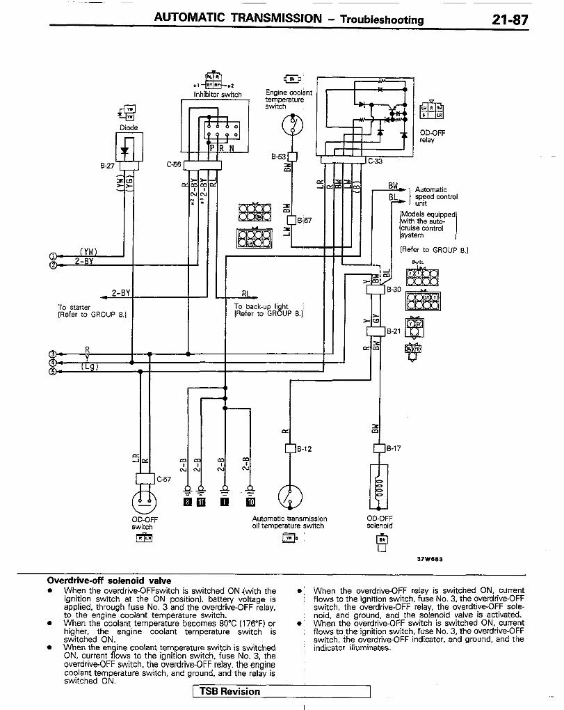
WERDRIVE CONTROL SYSTEM CIRCUIT
I
To alternator [Refer to GROUP 8.1
q
To combination meter * o*85-w (Refr. ._ rnn, In n 1
To turn signal flasher “not IRefer to GROW 8.1
R&i;mer control * BY
[Refer to GROUP 8.1
GO 6 r
Remarks (1) For information concerning the ground points (example:
0). refer to Group 8. I21 The symbols 0, 0. etc. indicate that the wiring is
connected (using the same numerical svmboi) to the facing page. (In other words, 0 on the right page is connected to 0 on the left page.)
Wiring color code 8: Black 6r: Brown G: Green LI: Lrght blue 0: Orange P: Pink I Gr: Gray L: BIue Lg: Light green R: Red Y: Yellow W: White
0 PERATION Automatic transmission oil temperature warning light . When the ignition switch is placed in the “ON” position
without starting the engine, current will flow to fuse No. 3. the automatic transmission oil temperature warning light, diode alternator, and the ground, and the warning lights will light. This is a circuit for the purpose of checking for bulb circuit breakage, and the lights will go out when the engine is started.
l When the engine is started, current flows to the ignition switch. fuse No. 3, and the automatic transmrssion oil temperature warning light, the batten/ voltage will go to the oil temperature switch.
l When ATF temperature rises above 50°C (122”F), the oil temperature switch will go on.
l When the oil temperature switch goes on, current will flow to the ignitioi, switch, fuse No. 3, the automatic oil temperature warnfig light, oil temperature switch and the ground and the warning lights will go on.
TSB Revision
- ~
AUTOMATIC TRANSMISSION - Troubleshooting 21-87
@- (VW) o1 2-BY
* 2-BY
To starter [Refer to GROUP 8.1
[Refer to GROUP 8.1
Automatic transmission oil temperature switch
E3
Overdrive-off solenoid valve l When the overdrive-OFFswitch is switched ON (with the
ignition switch at the ON position). battery voltage is applied, through fuse No. 3 and the overdrive-OFF relay, to the engine coolant temperature switch.
0 When the coolant temperature becomes 80°C (176°F) or higher, the switched ON.
engine coolant temperature switch is
8 When the engine coolant temperature switch is switched ON, current flows to the ignition switch, fuse No. 3. the overdrive-OFF switch, the overdrive-OFF relay, the engine coolant temoerature switch, and around. and the relav is switched Oi\l.
1 TSB Revision
When the overdrive-OFF relay is switched ON, current flows to the ignition switch, fuse No. 3, the overdrive-OFF switch, the overdrive-OFF relay, the overdtive-OFF sole- noid, and ground, and the solenoid valve is activated. When the overdrive-OFF switch is switched ON, current flows to the ignition switch, fuse No. 3, the overdrive-OFF switch, ihe overdrive-OFF indicator, and ground, and the indicator illuminates.
~~lmlma gj- 2. : I,.&, __ _ -- __-.
21-88 AUTOMATIC TRANSMISSION - Service Adjustment Procedures
Filler plug
COLD lower limit
COLD
HOT upper limit
HOT lower limit
HOT
SERVICE ADJUSTMENT PROCEDURE& ;~$iSMISSION FLUID CHANGING AND INSPEC-
(1) Check the fluid level (automatic transmission and transfer case).
(2) For the checking procedures of automatic transmission fluid (ATF), see P.21-77.
(3) Check the transfer case oil level with the filler plug removed.
(4) The fluid level is okay if it is at the same level as the lowest point of the filler plug hole.
(5) Install the filler plug and gasket, and tighten to 30-35 Nm (22-25 ft.lbs.).
ATF CHANGING PROCEDURES
Caution If ATF change is required due to damage to the transmis- sion, be sure to clean the cooler system.
(I) Raise the vehicle on hoist. Place a drain container with large openig under the drain plug (located in bottom of the oil pan).
(2) Remove the drain plug to let ATF drain 13) install the drain plug and-new gasket and tighten to 16-23
Nm (13-17 ft.lds.).- Nm (13-17 ft.lds.).- (4) Refill ATF through the oil level gauge hole until its level (4) Refill ATF through the oil level gauge hole until its level
reaches the COLD lower limit of the level gauge. reaches the COLD lower limit of the level gauge. (5) Start the engine and allow to idle for at least two minutes. (5) Start the engine and allow to idle for at least two minutes.
Then. with the parkino brake and service brake applied, Then. with the parkino brake and service brake applied, move the selector lever through all positions and finally place in the “N” or “P” position.
(6) After the transmission is warmed up to the normal operating temperature, recheck the fluid level, which must be between the HOT upper limit and HOT lower limit marks.
(7) Insert the dipstick fully to prevent dirt from entering the . 37zozs( transmrssron. \ TSB Revision
AUTOMATIC TRANSMISSION - Service Adjustment Procedures 21-89
TRANSFER CASE OIL CHANGING PROCEDURES (I) Remove the filler plug. (2) Place a drain container with large opening under the drain
plug. (3) Remove the drain plug to let oil drain. (4) Install the drain plug and new gasket and tighten to 30-35
Nm (22-25 ftlbs.).
(5) Refill specified transfer case oil up to specified level. (6) Install the filler plug and gasket and tighten to 30-35 Nm
(22-25 ftlbs.).
THROlTLE CABLE CHECK AND ADJUSTME!?- (1) Check for defective or bent throttle lever or throttle cable
bracket. (2) Check that the distance between the inner cable stopper
and dust cover surface is within the standard value.
Standard value : O-l mm (O-.04 in.)
(3) If outside the standard value, adjust with adjusting nut.
PROPELLER SHAFT OIL SEALS REPLACEME!L=
Refer to P.21-11.
SPEEDOMETER CABLE REPLACEMENT Refer to P.21-11.
NzlFLUd
[ TSB Revision i

21-90 AUTOMATIC TRANSMISSION - Transmission Control
TRANSMISSION CONTROL REMOVAL AND INSTALLATION 4
1
/ 26 19’ 012
25
Removal steps
**
I, Plate B 2. Floor console
15. Snap ring
3. Overdrive switch connection I)+ 16. Spring e)+ 17. Cross- shaft bushing
4. Selector handle 5. Overdrive switch harness and front wir-
*+ 18. Cross_ shaft boot (B) +I) ++ 19. Select cross shaft .*
Ing narness connecuon 6. Cover 7. Inhibitor switch and front wiring harness
connection 8. Position indicator light and front wiring
harness connection 9. indicator panel
IO. Bracket assembly
++ I)+ 20. Transmission control rod (A) 21. Cap
1)4 22. Bushing e)+ 23. Cross shaft bracket (A)
H 24. Cross shaft boot e+ 25. Bushing *+ 26. Pin
11. Heat protector 12. Cotter pin
+w ++ 13. Transmission control rod /BI 14. Dust cover
[ TSB Revision
NOTE (1) Reverse the removal procedures to reinstall. (2) ++ : Refer to “Service Points of Removal”. (3) r)* : Refer to “Service Points of Installation”. (4) q : Non-reusable parts
I - .J

AUTOMATIC TRANSMISSION - Transmission Control 21-91
control rod (6)
SERVICE POINTS OF REMOVAL FJamAF 4. REMOVAL OF SELECTOR HANDLE
(I) Press the cover downward. (2) Disconnect the overdrive switch connector from the
selector handle.
(3) Remove the selector handle from the shift lever.
13. DISCONNECTION OF TRANSMISSION CONTROL ROD (B) (I) Disconnect the transmission control rod (B) from the
transmission control arm by lossening the nut from under the floor.
(2) Disconnect the select cross shaft from the heat protector.
(3) Disconnect the select cross shaft from transmission control rod B.
Transmission 19. REMOVAL OF SELECT CROSS SHAFT/ZO. TRANSMIS-
SION CONTROL ROD (A) (1) Disconnect the select cross shaft from transmission
control rod A.
r TSB Revision

AUTOMATIC TRANSMISSION - Transmission Control
-I
(2) Remove the dust cover, and then remove the snap ring that holds the spring.
(3) Remove the cross shaft bracket mounting bolts from the transfer assembly.
(4) Detach the cross shaft bracket from the bracket on the No. 1 crossmember side.
(5) Remove transmission control rod A from the transmis- sion.
SERVICE POlNTS OF INSTALLATION N2IIoAn‘ 26.APPLlCATlON OF GREASE TO PIN/25 BUSHING/24.
CROSS SHAFT BOOT/23. CROSS SHAFT BRACKET (A)/22. BUSHING/20. TRANSMISSION CONTROL ROD (A)/19. SELECT CROSS SHAFT/lS. CROSS SHAFT BOOT (B)/17. CROSS SHAFT BUSHING/lG. SPRING Apply a coating of the multipurpose grease to the bushing inner surface and the sliding parts shown in the figure.
13. INSTALLATION OF TRANSMISSION CONTROL ROD (B) (1) Move the transmission and shift lever to the “N”
position, and then install the transmission control arm and transmission control rod (B) as shown in the figure.
(2) Check, while driving, to be sure that the transmission is set to each range when the selector lever is shifted to each position.
(3) Check, while driving, to be sure that the overdrive is activated and cancelled correctly when the overdrive switch is used.
1 TSB Revision
AUTOMATIC TRANSMISSION - Transmission Control
dSASSEMBLY AND REASSEMBLY NZWE- 3
Removal steps
1. Position indicator light 18 r)+ 2. Inhibitor switch
3. Overdrive switch l 4 4. Pushbutton
5. Spring 8 6. Selector handle
I)* 7. Bushings I)* 8. Transmission control arm
9. Shift lever ** 10. Sleeve l * 11. Spring I)* 12. Rod assembly
13. Bracket
NOTE (I) Reverse the disassembly procedures to reassemble. (2) I)+ : Refer to “Service Points of Reassembly”.
Overdrive switch \
\ Selector handle
m k!zl 00 0
INSPECTION N2lmAC l Check for unusual wear of the bracket’s detent plate part,
rod end pin, each bushing, pushbutton and sleeve contact surface.
l Check for weakness of the spring. l Check the operation of the overdrive switch. (Check the
continuity.) When the overdrive switch is OFF: continuity When the overdrive switch is ON: non-continuity
Inhibitor switch
I Check the continuity with the select lever at each position.
NOTE m indicates that there is continuity between the terminals.
rTSB Revision 1
21-94 AUTOMATIC TRANSMISSION - Transmission Control
SERVICE POlriliS OF REASSEMBLY N2mu& 12. APPLICATION OF GREASE TO ROD ASSEMBLY/II.
SPRING/lO. SLENE/8. TRANSMlSSlON CONTROL ARM/7. BUSHINGS/A PUSHBUTTON Apply the multipurpose grease to each sliding part of the lever.
Pushbutton side
Sleeve
Selector lever
25
“N” position
Pin at the end of the rod
mm (in.) cm565
nm fin.1
10. INSTALLATION OF SLEEVE Move the selector lever to the “N” position, and turn the sleeve so that the angled surface of the sleeve is at the pushbutton side, At this time, adjust the clearance bet- ween the sleeve and the selector lever so that it is the stan- dard value.
Standard value : 15.2-15.9 mm (.60-.62 in.]
NOTE Move the 6 part of the sleeve to the pushbutton side (driver’s seat side).
2. INSTALLATION OF INHIBITOR SWITCH (1) Temporarily install the inhibitor switch. (2) Set the shift lever so that the pin at the end of the rod is
at the position shown in the figure.
(3) Using a circuit tester between 2-BY and 2-BY of the inhibitor switch connector, check the continuity when the inhibitor switch is moved back and forth, and mark the bracket.
(4) Tighten the inhibitor switch mounting screws at the position where the clearance between the inhibitor switch and the selector lever is the specified distance.
. ; I Gevision I
-.
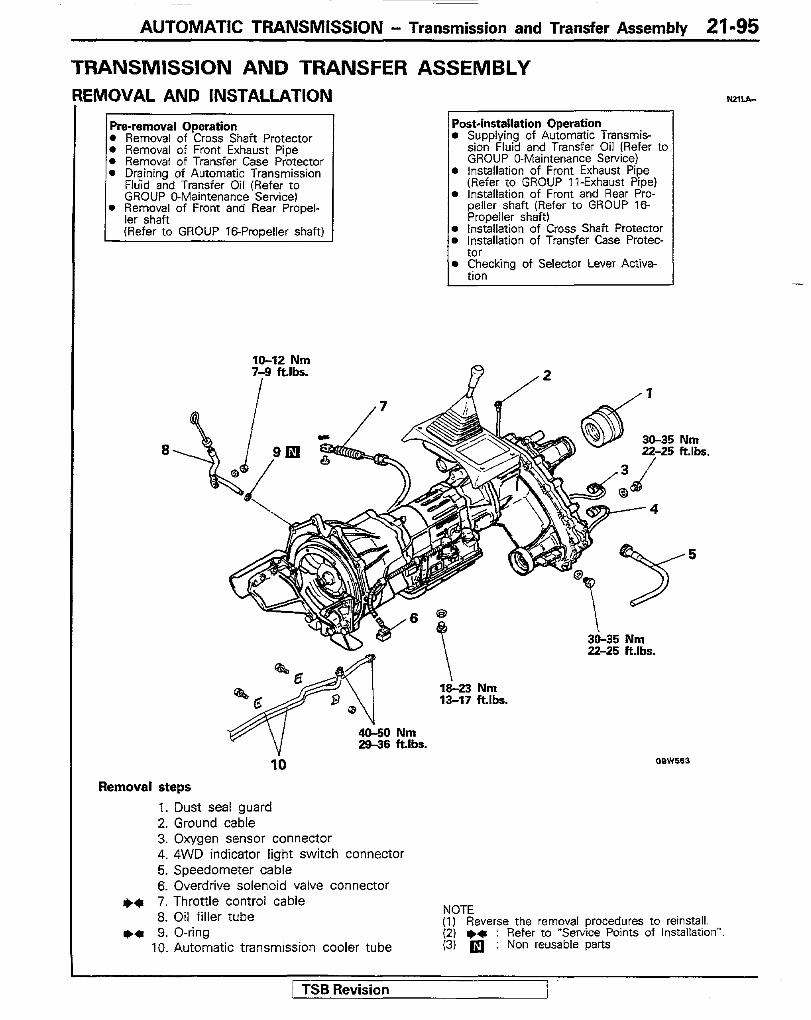
AUTOMATIC TRANSMISSION - Transmission and Transfer Assembly 21-95
TRANSMISSION AND TRANSFER ASSEMBLY EMOVAL AND INSTALLATION
Pre-removal Operation Post-installation Operation l Removal of Cross Shaft Protector l Supplying of Automatic Transmit 0 Removal of Front Exhaust Pipe sion Fluid and Transfer Oil (Refer tc 0 Removal of Transfer Case Protector GROUP O-Maintenance Service) l Draining of Automatic Transmission l Installation of Front Exhaust Pipe
Fluid and Transfer Oil (Refer to (Refer to GROUP II-Exhaust Pipe) GROUP O-Maintenance Service) l Installation of Front and Rear Pro-
l Removal of Front and Rear Propel- peller shaft (Refer to GROUP 16- ler shaft Propeller shaft) (Refer to GROUP 16-Propeller shaft) l Installation of Cross Shaft Protector
l Installation of Transfer Case Protec- tor
IO-12 Nm 7-9 ft.lbs.
I
Removal steps
l Checking of Selector Lever Aotiva- tinn
1. Dust seal guard 2. Ground cable 3. Oxygen sensor connector 4. 4WD indicator light switch connector 5. Speedometer cable 6. Overdrive solenoid valve connector
+q 7. Throttle control cable 8. Oil filler tube
l * 9. O-ring 10. Automatic tmnsmlssion cooler tube
NOTE (1) Reverse the removal procedures to reinstall. (2) l + : Refer to “Service Points of Installation”. (3) a : Non reusable parts
1 TSB Revision I
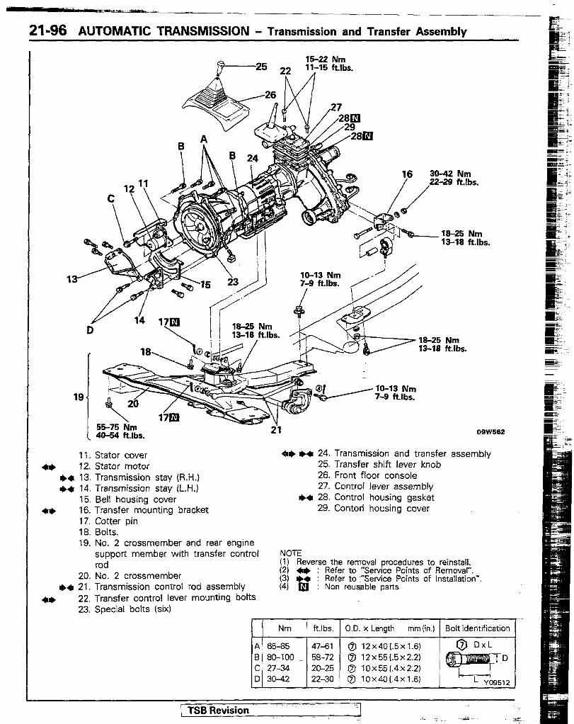
21-96 AUTOMATIC TRANSMISSION - Transmission and Transfer Assembly
OSW562
11. Stator cover +I* ++ 24. Transmission and transfer assembly
+* 12. Stator motor 25. Transfer shift lever knob +* 13. Transmission stay (R.H.) 26. Front floor console e* 14. Transmission stay (L.H.) 27. Control lever assembly
15. Bell housing cover I)* 28. ControT housing gasket 4* 16. Transfer mounting bracket 29. Contorl housing cover
17. Cotter pin 18. Bolts. 19. No. 2 crossmember and rear engine
support member with transfer control NOTE rod (1) Reverse the removal procedures to reinstall.
20. No. 2 crossmember 12) +I) : Refer to “Service Points of AemovaI”.
+a 21. Transmission control rod assembly (3) * : Refer to “Service Points of Installation*. (41 •j : Non reusable parts
4+ 22. Transfer control lever mounting bolts 23. Special bolts (six)
/ TSB Revision ‘= I
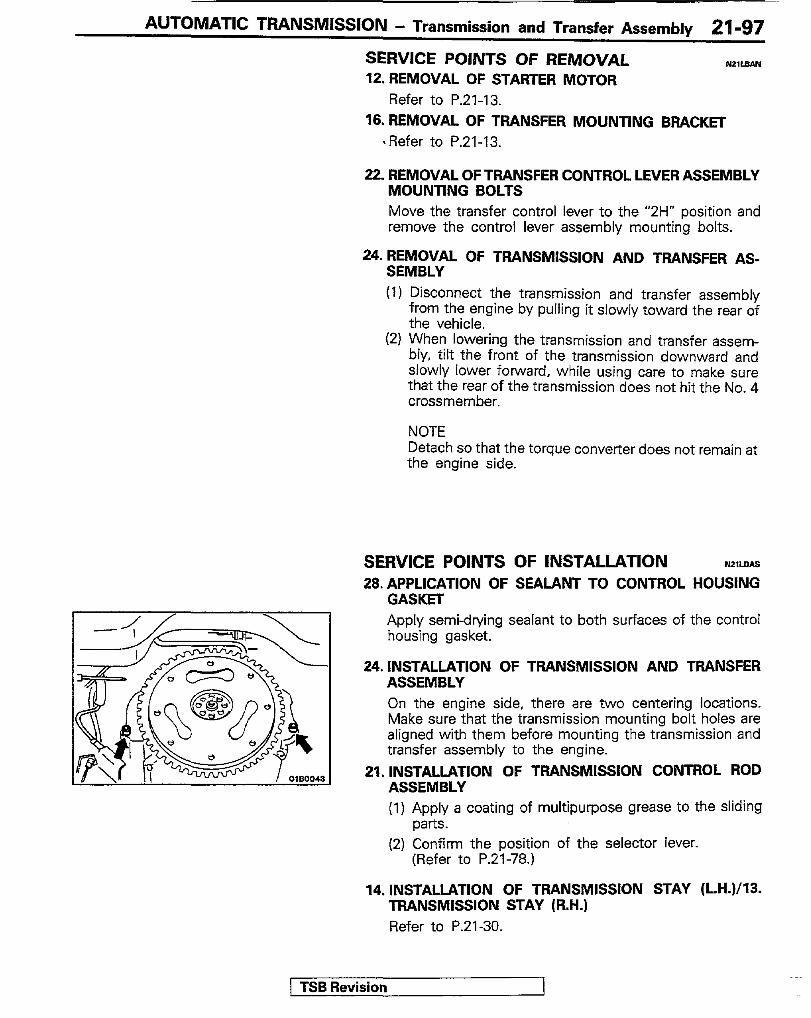
AUTOMATIC TRANSMISSION - Transmission and Transfer Assembly 21-97
SERVICE POINTS OF REMOVAL 12. REMOVAL OF STARTER MOTOR
Refer to P.Zl-13.
N21LBAN
16. REMOVAL OF TRANSFER MOUNTING BRACKET ‘Refer to P.21-13.
22. REMOVAL OF TRANSFER CONTROL LEVER ASSEMBLY MOUNTING BOLTS Move the transfer control lever to the “2H” position and remove the control lever assembly mounting bolts.
24. REMOVAL OF TRANSMISSION AND TRANSFER AS- SEMBLY (I) Disconnect the transmission and transfer assembly
from the engine by pulling it slowly toward the rear of the vehicle.
(2) When lowering the transmission and transfer assem- bly, tilt the front of the transmission downward and slowly lower forward, while using care to make sure that the rear of the transmission does not hit the No. 4 crossmember.
NOTE Detach so that the torque converter does not remain at the engine side.
SERVICE POINTS OF INSTALLATION %?,LDAs 28. APPLICATION OF SEALANT TO CONTROL HOUSING
GASKET Apply semi-drying sealant to both surfaces of the control housing gasket.
24. INSTALLATION OF TRANSMISSION AND TRANSFER ASSEMBLY On the engine side, there are two centering locations. Make sure that the transmission mounting bolt holes are aligned with them before mounting the transmission and transfer assembly to the engine.
21. INSTALLATION OF TRANSMlSSlON CONTROL ROD ASSEMBLY (1) Apply a coating of multipurpose grease to the sliding
parts. (2) Confinn the position of the selector lever.
(Refer to P.21-78.)
14. INSTALlATlON OF TRANSMlSSlON STAY (L.H.)/13. TRANSMISSION STAY (R.N.) Refer to P.21-30.
1 TSB Revision
21-98 AUTOMATIC TRANSMISSION - Transmission and Transfer Assembly
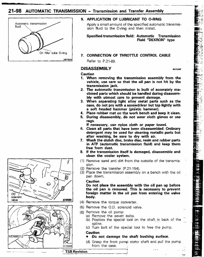
Automatic transmission 9. APPLICATION OF LUBRICANT TO O-RING
Apply a small amount of the specified automatic transmis- sion fluid to the O-ring and then install.
Specified transmission fluid: Automatic Transmission Fluid “DEXRON” type
7. CONNECTION OF THROTTLE CONTROL CABLE
Refer to P.21-99.
DlSASSEMBLY Caution 1. When removing the transmission assembly from the
vehicle, use care so that the oil pan is not hit by the transmission jack.
2. The automatic transmission is built of accurately ma- chined parts which should be handled during disassem- bly with utmost care to prevent damage.
3. When separating light alloy metal parts such as the case, do not pry with a screwdriver but tap lightly with a soft headed hammer (p&tic hammer).
4. Place rubber mat on the work bench and keep it clean. 5. During disassembly, do not wear cloth gloves or use
rags. If necessary, use nylon cloth or paper towel.
6. Clean all parts that have been disassembled. Ordinary detergent may be used for cleaning metallic parts but after washing, be sure to dry with air.
7. Wash the clutch disc, brake disc, resin and rubber parts in ATF (automatic transmission fluid) and keep them free from dust.
5. If the transmission itself is damaged, disassemble and clean the cooler system.
(I) Remove sand and dirt from the outside of the transmis- sion.
(2) Remove the transfer (P.21-154). (3) Place the transmission assembly on a bench with the oil
pan down. Caution Do not place the assembly with the oil pan up before the oil pan is removed. This is necessary to prevent foreign matter in the oil pan from entering the valve body.
(4) Remove the torque converter. (5) Remove the O.D. solenoid valve. (6) Remove tt,e oil pump:
(a) Remove the seven bolts. (b) Position the special tool on the shaft in back of the
spline. (c) Turn bolt of the special tool to free the pump. Caution l Do not damage the shaft bushing surface. (d) Grasp the front pump stator shaft and pull the pump
from the case. ; I\“-.\ 1 3720004
jRevision r ~.

AUTOMATIC TRANSMISSION - Transmission and Transfer Assembly 21-99
(7) Watch for the bearing and race behind the oil pump.
(8) Remove the torque converter housing: (a) Remove the two 12-mm bolts and four IO-mm bolts. (b) While holding the input shaft, remove the converter
housing.
(9) Remove the adapter and gasket. (lO)Remove the governor mounting bolt. (1 l)Lift up the governor retaining ring lightly by a screwdriver
and remove the governor assembly from the output shaft.
(12) Remove the governor strainer: (a) Remove the four screws and plate. (b) Remove the strainer from the case.
(13) Remove the oil pan and gasket: (a) Remove the fourteen bolts. (b) Remove the oil pan with the transmission case lifted. Caution l Do not turn the transmission over as this will
contaminate the valve body by foreign materials collected in the bottom of oil pan.
TSB Revision
21-100 AUTOMATIC TRANSMISSION - Transmission and Transfer Assembly
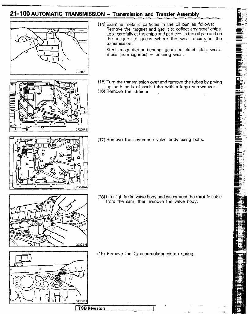
(14) Examine metellic particles in the oil pan as follows: Remove the magnet and use it to collect any steel chips. Look carefully at the chips and particles in the oil pan and on the magnet to guess *here the wear occurs in the transmission: Steel (magnetic) = bearing, gear and clutch plate wear. Brass (nonmagnetic) = bushing wear.
(15) Turn the transmission over and remove the tubes by prying up both ends of each tube with a large screwdriver.
(16) Remove the strainer. _
(17) Remove the seventeen valve body fixing bolts.
(18) Lift slightly the valve body and disconnect the throttle cable from the cam, then remove the valve body.
(19) Remove the CZ accumulator piston spring.
( TSB Revision -
..-

AUTOMATIC TRANSMISSION - Transmission and Transfer Assembly 21-101
(20) Using a 10 mm (.39 in.) socket, push the plastic throttle cable retainer out of the transmission case to remove the cable with retainer.
(21) Position a rag to catch each piston. Blow low-pressure compressed air (100 kPa, 14.5 psi) into each of the holes shown to let the piston into the rag. Remove the pistons and springs. Caution l Keep face away to avoid injury. l Do not use high-pressure air.
(22) Remove the parking lock linkage: (a) Remove the cam plate. (b) Remove the parking lock rod. (c) Remove the spring, pivot pin and parking lock pawl.
(23) Remove the manual lever and shaft: (a) Using a hammer and punch, drive out the pin. (b) C$dz. the shaft out the case and remove the detent
(24) Place the transmission on a cylindrical stand for mure efficient work.
Caution l Place shop rags between the case and stand to
avoid damaging the case.
1 TSB Revision
21-q 02 AUTOMATIC TFIANSMISSION - Transmission and Transter Assembly
j TSB fbvision / -1 .-
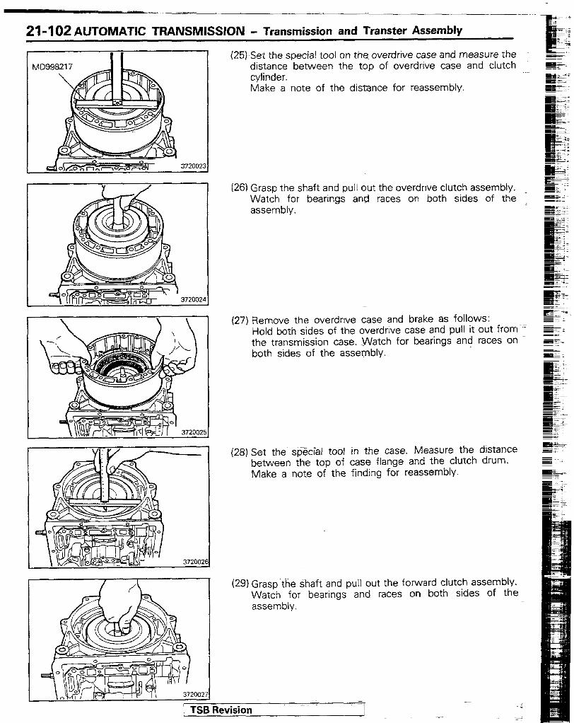
(25) Set the special tool on the overdrive case and measure the distance between the top of overdrive case and clutch cylinder. Make a note of the distance for reassembly.
(26) Grasp the shaft and pull out the overdnve clutch assembly. Watch for bearings and races on both sides of the assembly.
(27) Remove the overdnve case and brake as follows: Hold both sides of the overdrive case and pull it out from the transmission case. -Watch for bearings and races on both sides of the assembly.
(28) Set the sfjecial tool in the case. Measure the distance between the top of case flange and the clutch drum. Make a note of the finding for reassembly.
(29) Grasp the-*aft and pull out the forward clutch assembly. Watch for bearings and races on both sides of the assembly.
AUTOMATIC TRANSMISSION - Transmission and Transfer Assembly 21-103
372002:
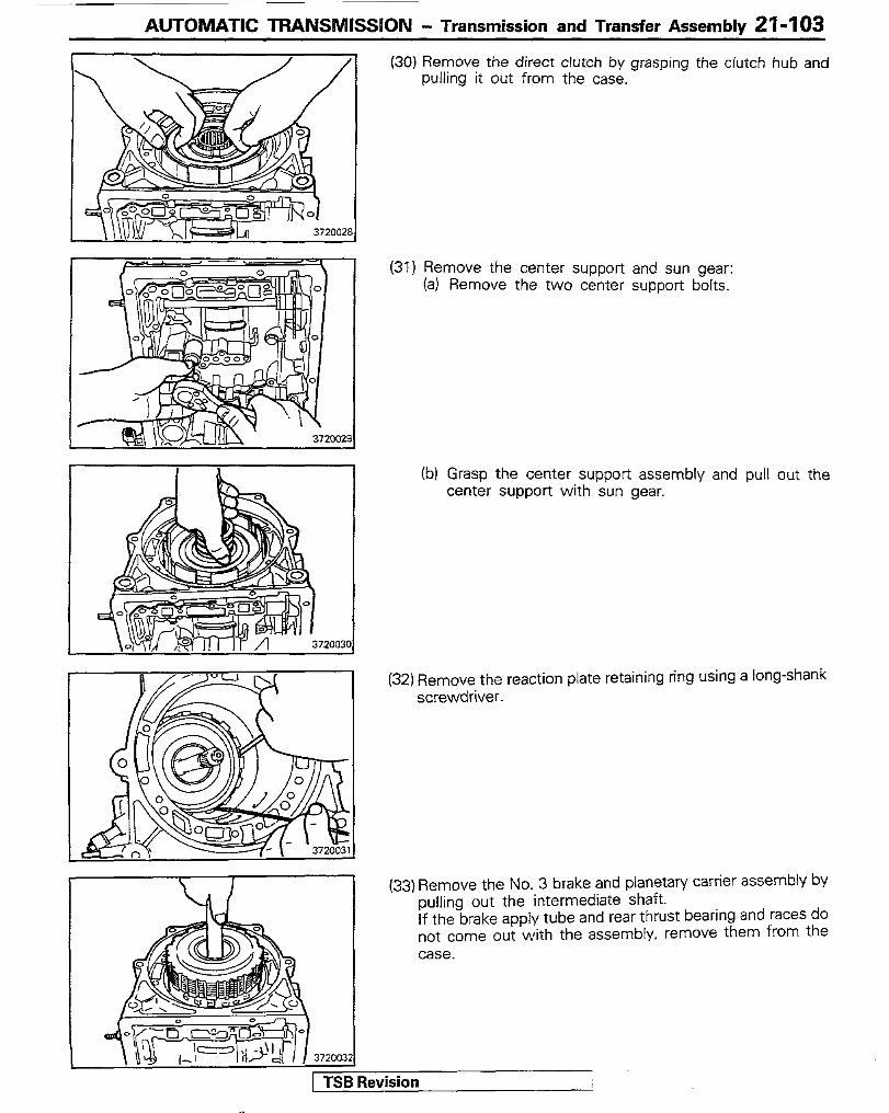
(30) Remove the direct clutch by grasping the clutch hub and pulling it out from the case.
(31) Remove the center support and sun gear: (a) Remove the two center support bolts.
Ib) Grasp the center support assembly and pull out the center support with sun gear.
(32) Remove the reaction plate retaining ring using a long-shank screwdriver.
(33) Remove the No. 3 brake and planetary carrier assembly by pulling out the intermediate shaft. If the brake apply tube and rear thrust bearing and races do not come out with the assembly, remove them from the case.
ievision I
21-104 AUTOMATIC TRANSMISSION - Transmission and Transfer Assembly
35515
REASSEMBLY Caution
NZWAF
l Before assembly, make sure that all component assemblies are assembled correctly.
l If something wrong is found in a certain component assembly while assembly, inspect and repair this assembly immediately.
GENERAL ASSEMBLY NOTES @) The automatic transmission is composed of highly
precision-finished parts, necessitating careful inspec- tion before assembly because even a small nick could cause fluid leakage or affect performance.
@ Before assembling new clutch discs, soak them in ATF for at least two hours.
@I Apply ATF on sliding or rotating surfaces of the parts before assembly.
@ Use petroleum jelly to keep the small parts in their
@ g?%i use sealant or adhesive cements on gaskets and similar parts.
@ When assembling the transmission, be sure to use new gaskets and O-rings.
@ Dry all parts by blowing with compressed air. Never use shop rags.
@ Be sure to install the thrust bearings and races in the correct direction and position.
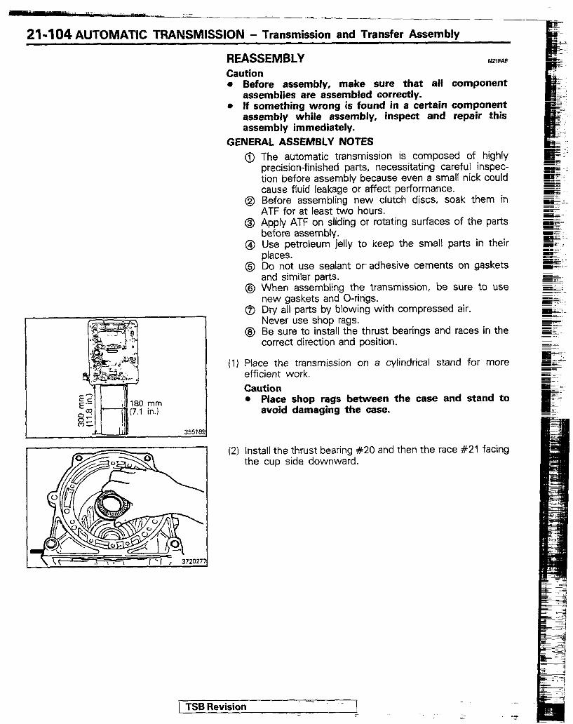
(1) Place the transmission on a cylindrical stand for more efficient work. Caution l Place shop rags between the case and stand to
avoid damaging the case.
(2) Install the thrust bearing #20 and then the race #21 facing the cup side downward.
j TSB Revision I -- ._
: Lo __
AUTOMATIC TRANSMISSION - Transmission and Transfer Assembly 21-105
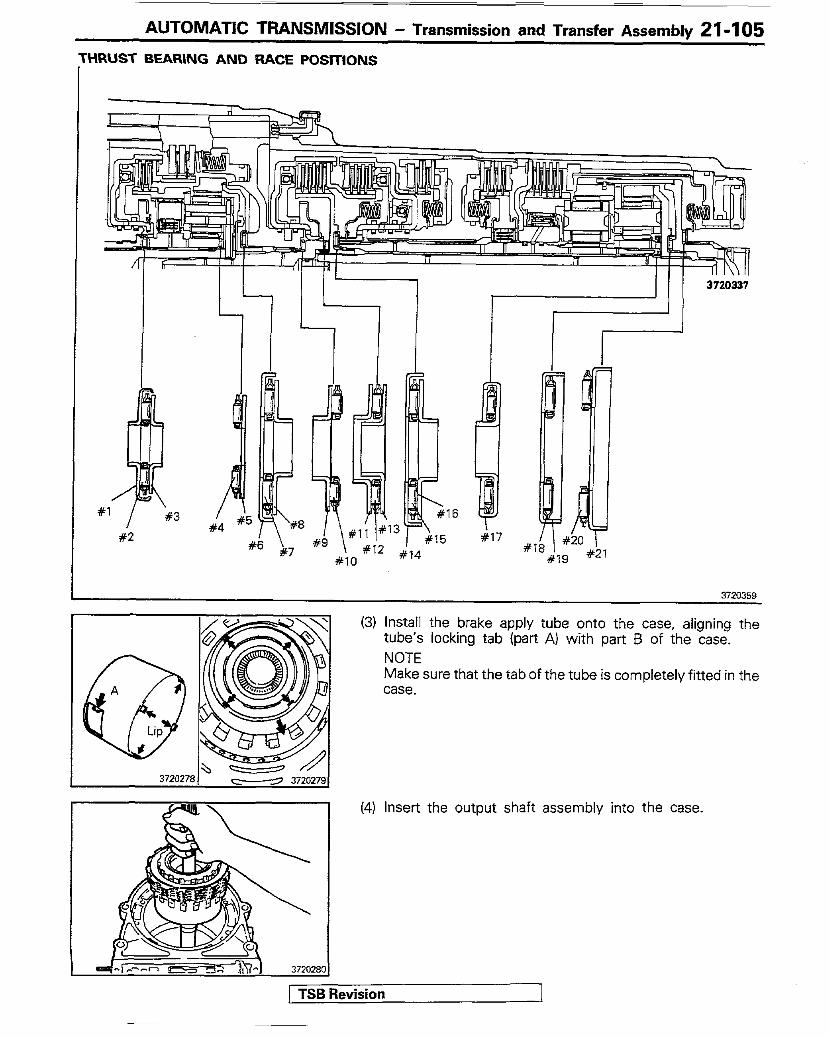
‘HRUST BEARING AND RACE POSITIONS
16
I I 3720337
3720359
(3) Install the brake apply tube onto the case, aligning the tube’s locking tab (part A) with part B of the case. NOTE Make sure that the tab of the tube is completely fitted in the case.
(4) Insert the output shaft assembly into the case.
1 0 1 TSB Revision 1
21-106 AUTOMATIC TRANSMISSION - Transmission and Transfer Assembly
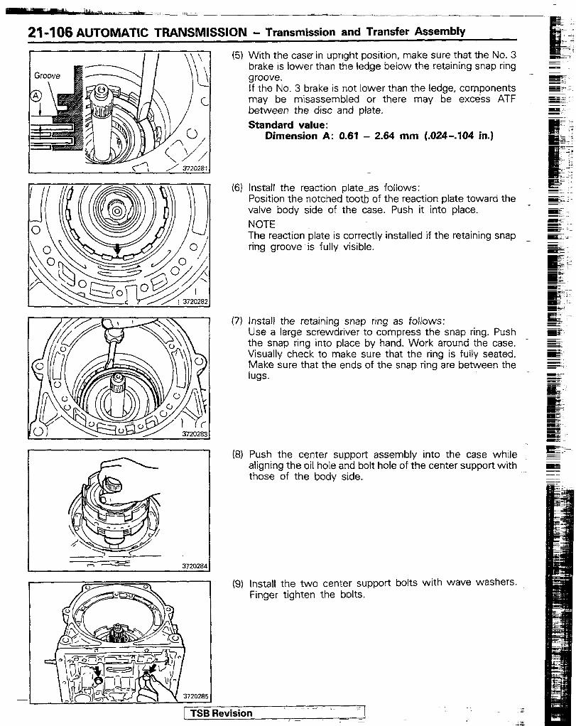
(5)
(6)
(7)
KY
(9)
With the case in upright position, make sure that the No. 3 brake is lower than the ledge below the retaining snap ring groove. If the No. 3 brake is not lower than the ledge, components may be misassembled or there may be excess ATF between the disc and plate. Standard value:
Dimension A: 0.61 - 2.64 mm (.024-.I04 in.)
Install the reaction plate-as follows: Position the notched tooth of the reaction plate toward the valve body side of the case. Push it into place. NOTE The reaction plate is correctly installed if the retaining snap ring groove is fully visible.
Install the retaining snap ring as follows: Use a large screwdriver to compress the snap ring. Push the snap ring into place by hand. Work around the case. - Visually check to make sure that the ring is fully seated. Make sure that the ends of the snap ring are between the lugs.
Push the center support assembly into the case whrle aligning the oil hole and bolt hole of the center support with those of the body side.
Install the two center support bolts with wave washers. Finger tighten the bolts.
1 TSB Revision
AUTOMATIC TRANSMISSION - Transmission and Transfer Assemblv 21-I 07
ulD998217 \/F
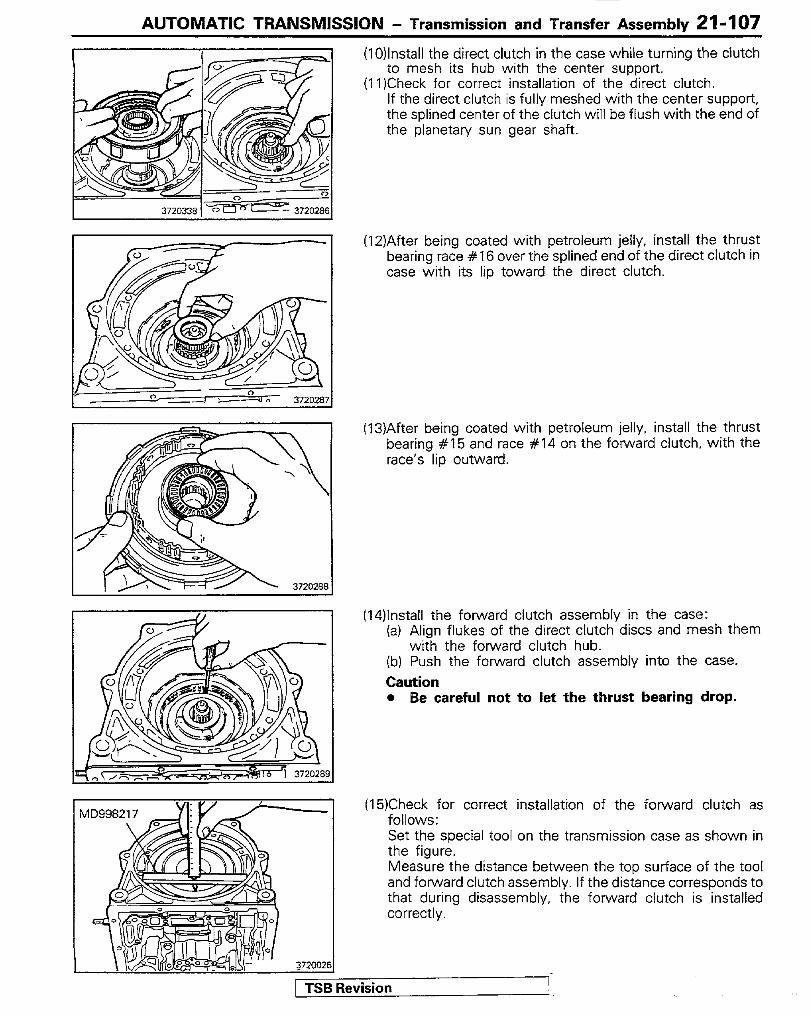
(10)lnstall the direct clutch in the case while turning the clutch to mesh its hub with the center support.
(11)Check for correct installation of the direct clutch. If the direct clutch is fully meshed with the center support, the splined center of the clutch will be flush with the end of the planetary sun gear shaft.
(12)After being coated with petroleum jelly, install the thrust bearing race #I 6 over the splined end of the direct clutch in case with its lip toward the direct clutch.
(13)After being coated with petroleum jelly, install the thrust bearing #I5 and race #I4 on the forward clutch, with the race’s lip outward.
(14)lnstall the forward clutch assembly in the case: (a) Align flukes of the direct clutch discs and mesh them
with the forward clutch hub. (b) Push the forward clutch assembly into the case. Caution 0 Be careful not to let the thrust bearing drop.
TSB Revision
(15)Check for correct installation of the forward clutch as follows: Set the special tool on the transmission case as shown in the figure. Measure the distance between the top surface of the tool and forward clutch assembly. If the distance corresponds to that during disassembly, the forward clutch is installed correctly.
21-108 AUTOMATIC TRANSMISSION - Transmission and Transfer Assembly
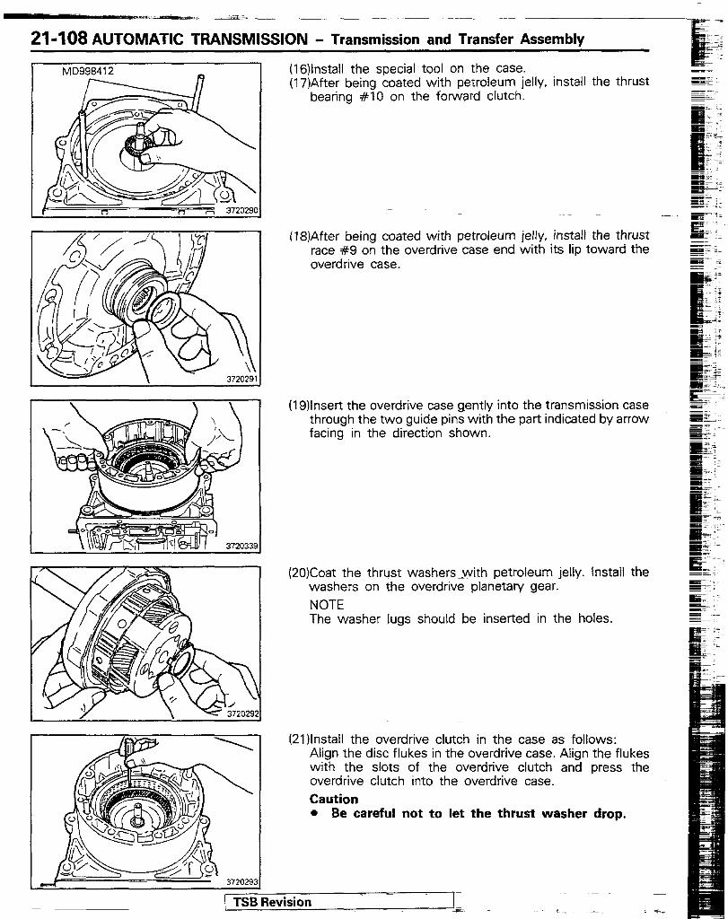
MD998412 (16)lnstall the special tool on the case. (17)After being coated with petroleum jelly, install the thrust
bearing #lO on the forward clutch.
(18)After being coated with petroleum jelly, install the thrust race #9 on the overdrive case end with its lip toward the overdrive case.
(19)lnsert the overdrive case gently into the transmission case through the two guide pins with the part indicated by arrow facing in the direction shown.
(20)Coat the thrust washers&with petroleum jelly. Install the washers on the overdrive planetary gear. NOTE The washer lugs should be inserted in the holes.
( TSB Revision
(2l)lnstali the overdrive clutch in the case as follows: Align the disc flukes in the overdrive case. Align the flukes with the slots of the overdrive clutch and press the overdrive clutch into the overdrive case. Caution l Be careful not to let the thrust washer drop.
I MD998217
372002
AUTOMATIC TRANSMISSION - Transmission and Transfer Assembly 21-109
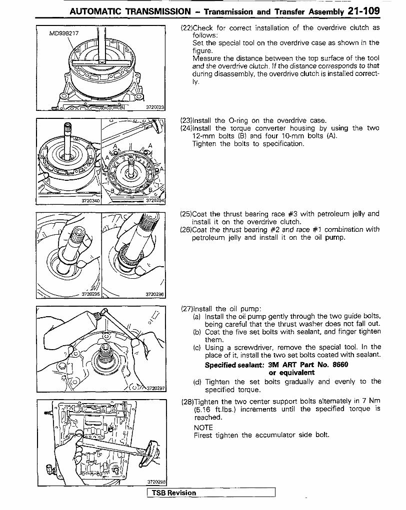
(22)Check for correct installation of the overdrive clutch as follows: Set the special tool on the overdrive case as shown in the figure. Measure the distance between the top surface of the tool and the overdrive clutch. If the distance corresponds to that during disassembly, the overdrive clutch is installed correct- Iv.
(23)lnstall the O-ring on the overdrive case. (24)lnstall the torque converter housing by using the two
12-mm bolts (B) and four IO-mm bolts (A). Tighten the bolts to specification.
(25)Coat the thrust bearing race #3 with petroleum jelly and install it on the overdrive clutch.
(26)Coat the thrust bearing #2 and race #I combination with petroleum jelly and install it on the oil pump.
(27)lnstall the oil pump: (a)
(b)
(cl
(d)
Install the oil pump gently through the two guide bolts, being careful’ that the thrust washer does not fall out. Coat the five set bolts with sealant, and finger tighten them. Using a screwdriver, remove the special tool. In the place of it, install the two set bolts coated with sealant. Specifiedsealant: 3M ART Part No. 8666
or equivalent Tighten the set bolts gradually and evenly to the specified torque.
(28)Tighten the two center support bolts alternately in 7 Nm (5.16 ftlbs.) increments until the specified torque is reached. NOTE Firest tighten the accumulator side bolt.
1 TSB Revision
21-1 IO AUTOMATIC TRANSMlSSlON - Transmission and Transfer Assembly
372030'
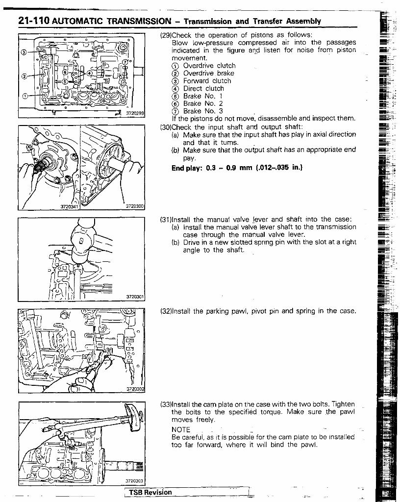
(29)Check the operation of pistons as follows: Blow low-pressure compressed air into the passages indicated in the figure and listen for noise from piston movement. @ Overdrive clutch @ Overdrive brake @ Forward clutch @ Direct clutch @ Brake No. 7 @ Brake No. 2 @ Brake No. 3 If the pistons do not move. disassemble and inspect them.
(30)Check the input shaft and output shaft: (a) Make sure that the input shaft has play in axial direction
and that it turns. (b) Make sure that the output shaft has an appropriate end
pay. End play: 0.3 - 0.9 mm (.0X2-.035 in.1
(31Jinstall the manual valve lever and shaft into the case: (a) Install the manual valve lever shaft to the transmission
case through the manual valve lever. (b) Drive in a new slotted spring pin with the slot at a right
angle to the shaft.
(32)lnstall the parking paw), pivot prn and spring in the case.
(33)lnstall the cam plate on the case with the two bolts. Tighten the bolts to the specified torque. Make sure the paw1 moves freely. NOTE Be careful, as it is possible for the cam plate to be installed too far forward, where it will bind the pawl.
; TSR Revision
AUTOMATIC TRANSMISSION - Transmission and Transfer Assemblv z!-‘lll
I 372000.3
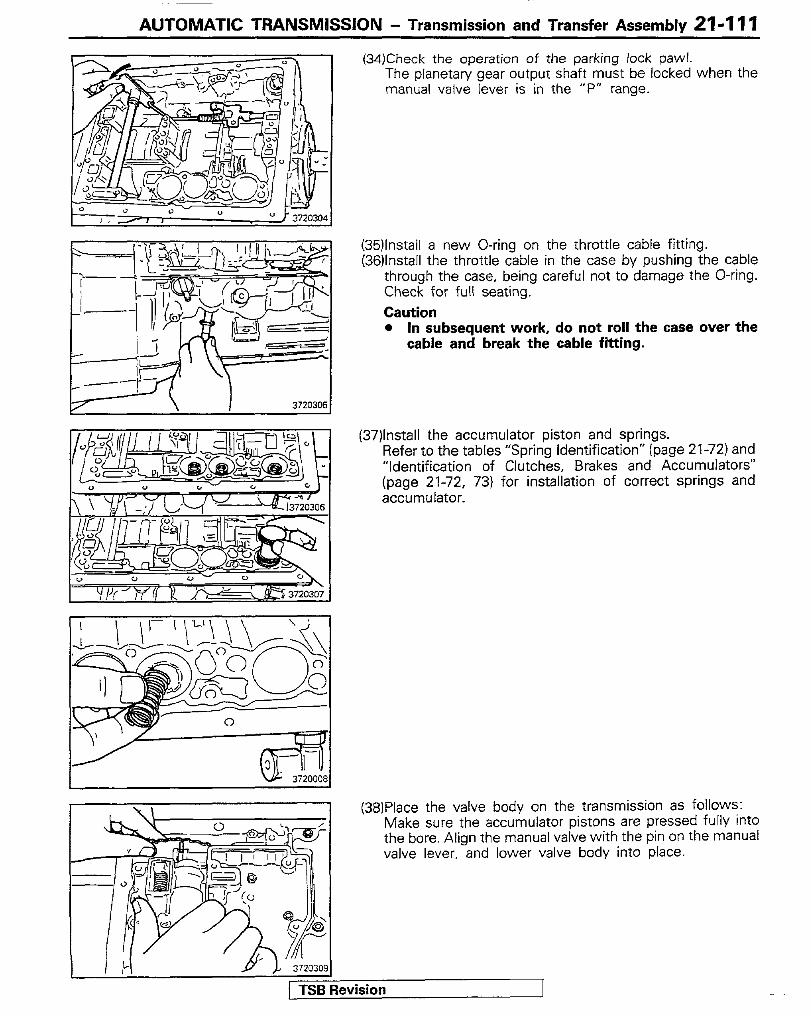
(34)Check the operation of the parking lock paw/. The planetary gear output shaft must be locked when the manual valve lever is in the “P” range.
(35)lnstall a new O-ring on the throttle cable fitting. (36)lnstall the throttle cable in the case by pushing the cable
through the case, being careful not to damage the O-ring. Check for full seating. Caution l In subsequent work, do not roll the case over the
cable and break the cable fi%ting.
(37)lnstall the accumulator piston and springs. Refer to the tables “Spring identification” (page 21-72) and “Identification of Clutches, Brakes and Accumulators” (page 21-72, 73) for installation of correct springs and accumulator.
(38)Place the valve body on the transmission as follows: Make sure the accumulator pistons are pressed fully into the bore. Align the manual valve with the pin on the manual valve lever, and lower valve body into place.
1 TSR Revision I
21-l 12 AUTOMATIC TRANSMISSION - Transmission and Transfer Assembly
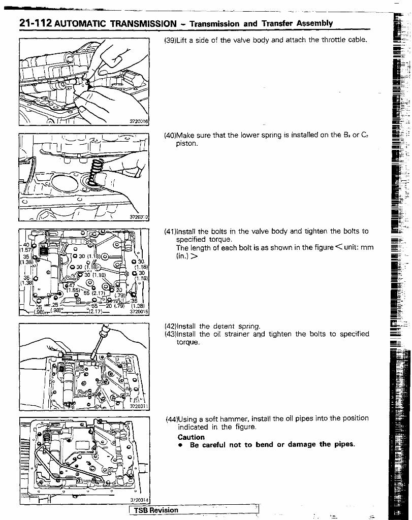
(39)Lift a side of the valve body and attach the throttle cable.
(40)Make sure that the lower spring IS installed on the BI or C? piston.
(4l)lnstall the bolts in the valve body and tighten the bolts to specified torque. The length of each bolt is as shown in the figure < unit: mm (in.) >
(42)lnstall the detent spring. (43)lnstall the oil strainer and tighten the bolts to specified
torque.
(44)Using a soft hammer, install the oil pipes into the position indicated in the figure. Caution l Be careful not to bend or damage the pipes.
- I
3720314
1 TSB Revision _ ‘1

AUTOMATIC TRANSMISSION - Transmission and Transfer Assembly 21-I 13
(45)lnstalI the magnet in the oil pan and install the oil pan with a new gasket. Caution l Make sure that the magnet does not interfere with
the oil pipes.
(46)lnstall the drain plug with a new gasket.
(47)lnstall the governor line strainer on the transmission case and then install the plate.
(48)lnsert a slot screwdriver between the governor retaining ring and governor body and install the governor to the output shaft.
(49)Install the adapter and gasket.
(50)lnstail the O.D. solenoid.
Caution Be sure to use two O-rings.
(5l)lnstall torque converter to transmission. (52)lnstall the transfer assembly (P.21-162).
1 TSB Revision

21-q 14 AUTOMATIC TRANSMISSION - Transmission and Transfer Assembly
GENERAL NOTES ON DISASSEMBLY AND ASSEMBLY Of COMPO- NENT ASSEMBLIES GENERAL CLEANING NOTES: (1) All disassembled parts should be washed clean
and the fluid passages and hole blown through with compressed air to make sure that they are not clogged.
(2) The cleaning solvent used should be the rec- ommended ATF or kerosene.
(3) When using compressed air to dry parts, avoid spraying ATF or kerosene in your face.
PARTS HANDLING NOTES: (1) After cleaning. the parts should be arranged in
proper order to allow performing the inspec- tion, repairs, and reassembly with efficiency.
(2) When disassembling the valve body, be sure to keep each valve together with its own spring.
(3) New brake and clutch discs that are to be used for replacement must be soaked in ATF for at least two hours before assembly.
OIL PUMP
Oil pump body Drwe gear
W1NEAA
GENERAL ASSEMBLY NOTES: (1) All -oil seal rings, clutch discs, clutch plates,
rotating parts, and sliding surfaces should be coated with ATF prior to reassembly.
(2) All gaskets and O-rings should be replaced. (3) Make sure that the ends of a snap ring are not
aligned with one of the cutouts and are in- stalled in the groove correctly.
(4) If a worn bushing is to be replaced, the replacement must be made with the compo- nent assembly containing that bushing.
(5) Check thrust bearings and races for wear or damage. Replace if necessary.
(6) Use petroleum jelly to keep parts in their places.
Oil pump cover
I
I 011 Seat
Drwen gear Seal’rmg
3720342
[ TSB Revision
AUTOMATIC TRANSMISSION - Transmission and Transfer Assembly 21-115
r I
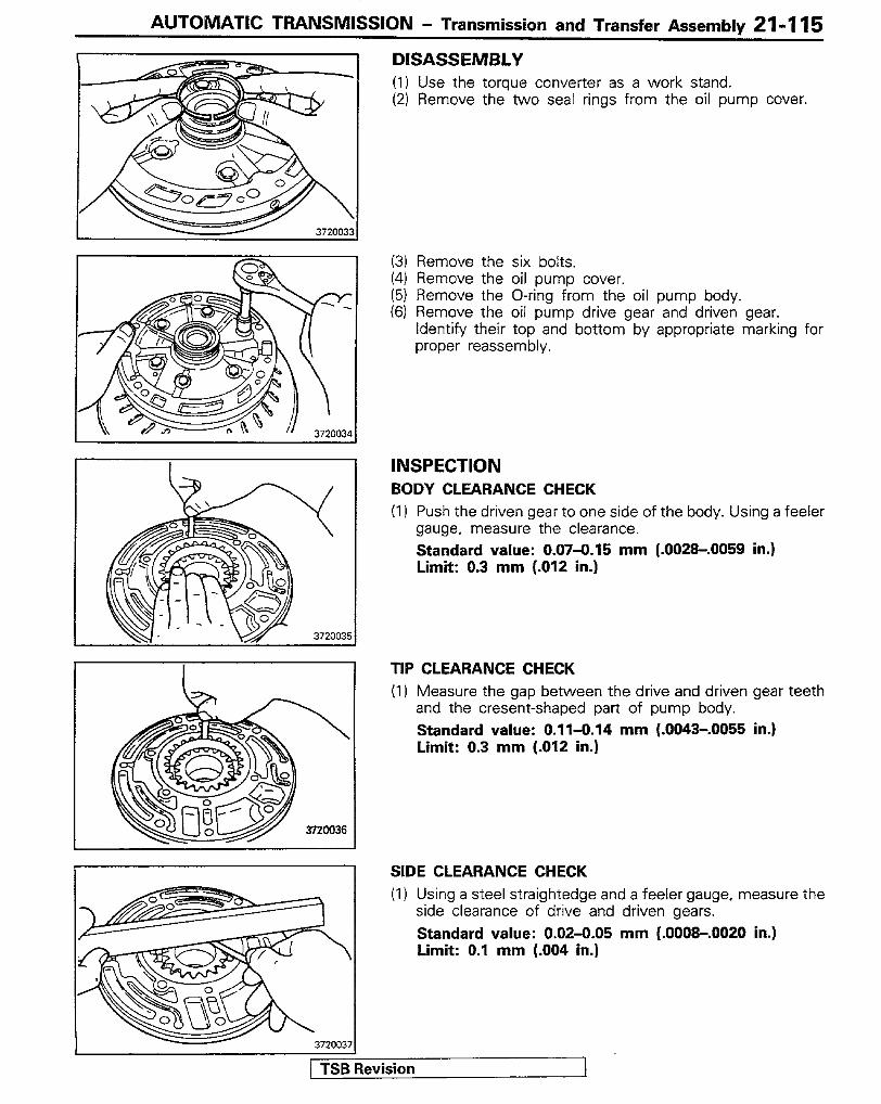
DISASSEMBLY (I) Use the torque converter as a work stand. (2) Remove the two seal rings from the oil pump cover.
(3) Remove the six bolts. (4) Remove the oil pump cover. (5) Remove the O-ring from the oil pump body. (6) Remove the oil pump drive gear and driven gear.
Identify their top and bottom by appropriate marking for proper reassembly.
INSPECTION BODY CLEARANCE CHECK (I) Push the driven gear to one side of the body. Using a feeler
gauge, measure the clearance. Standard value: 0.07-O-15 mm (.0029-.0059 in.) Limit: 0.3 mm (.012 in.)
TIP CLEARANCE CHECK (1) Measure the gap between the drive and driven gear teeth
and the cresent-shaped part of pump body. Standard value: 0.11-0.14 mm (.0043-.0055 in.) Limit: 0.3 mm (-012 in.)
SIDE CLEARANCE CHECK (1) Using a steel straightedge and a feeler gauge, measure the
side clearance of drive and driven gears. Standard value: 0.02-0.05 mm (.000&.0020 in.) Limit: 0.1 mm (.004 in.)
1 TSB Revision I
21-l 16 AUTOMATIC TRANSMISSION - Transmission and Transfer Assembly
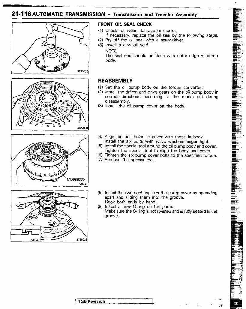
FRONT OIL SEAL CHECK
(1)
(2) (3)
Check for wear, damage or cracks. If necessary, replace the oil seal by the following steps. Pry off the oil seal with a screwdriver. install a new oil seal. NOTE The seal end should be flush with outer edge of pump body.
REASSEMBLY (1) (2)
(31
(41
(5)
I;;
(8)
(9)
Set the oil pump body on the torque converter. Install the driven and drive gears on the oil pump body in correct directions according to the marks put during disassembly. Install the oil pump cover on the body.
Align the bolt holes in cover with those in body. Install the six bolts with wave washers finger tight. install the special tool around the oil pump body and cover. Tighten the special tool to align the body and cover. Tighten the six pump cover bolts to the specified torque. Remove the special tool.
install the two seal rings on the pump cover by spreading apart and sliding them into the groove. Hook both ends by hand. Install a new O-ring on the pump. Make sure the O-ring is not twisted and is fully seated in the groove.
/ TSB Revision - = . .._ 25
AUTOMATIC TRANSMISSION - Transmission and Transfer Assembly 21-l 17
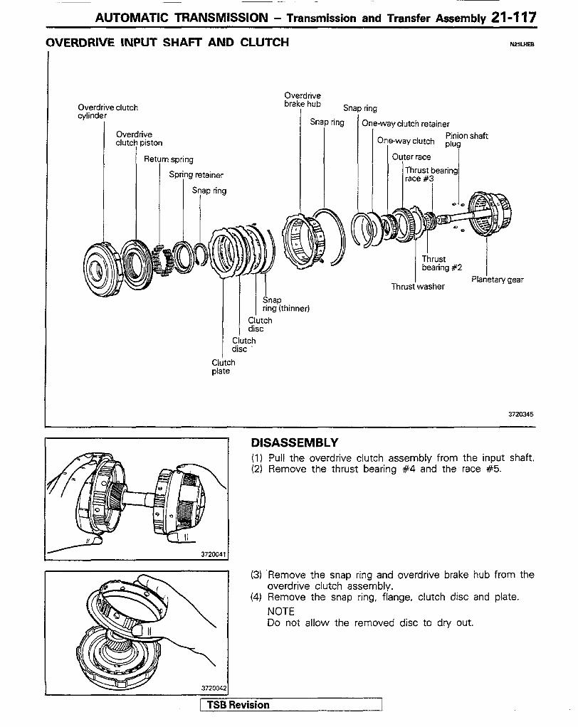
OVERDRIVE INPUT SHACT AND CLUTCH
Overdrive clutch piston
Retym spring
Spring retainer
Snap ring
Overdrive brake hub
I Sni 3P I Snap ring
I
?WLHEB
ring
mne ‘-way clutch retainer
Thrust bearing #2
I
Thrust washer Planetary gear
C(u$g’(thinner)
disc Clutch disc -
3720345
3720042
DISASSEMBLY (I) Pull the overdrive clutch assembly from the input shaft. (2) Remove the thrust bearing #4 and the race #5.
(3) ‘Remove the snap ring and overdrive brake hub from the overdrive clutch assembly.
(4) Remove the snap ring, flange. clutch disc and plate. NOTE Do not allow the removed disc to dry out.
/ TSB Revision

21-I ‘I8 AUTOMATIC TRANSMIWON - Transmission and Transfer Assembly
(5) Place the special tool on the spring retainer and compress the return springs with a shop press. Using a screwdriver, remove the snap ring.
(6) Remove the spring retainer and eighteen return springs.
(7) Assemble the overdrive clutch cylinder and piston set on the oil pump and blow otit the piston: (a) Slide the overdrive clutch cylinder and piston set onto
the oil pump. (b) Apply compressed air to the oil pump to remove the
piston. k) Remove the overdrive clutch cylinder from the oil
w-w
(8) Remove the O-rings from the overdrrve clutch piston. (9) Remove the snap ring from the overdrive plan&n/ gear
assembly. (10)Remove the one-way clutch retainer, one-way clutch and
outer race from the overdrive planetary gear assembly.
(11 IRemove the four pinion shaft plugs by a magnet. Caution l Keep the four plugs together to prevent losing
them.
(12)Remove the one-way clutch from the outer race.
3720047
1 TSB Revision T
AUTOMATIC TRANSMISSION - Transmission and Transfer Assembly 21-I 19
3720050
Front C I
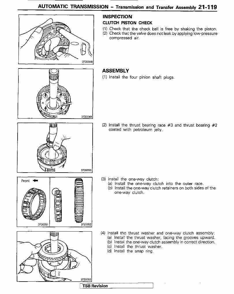
INSPECTION CLUTCH PISTON CHECK (I) Check that the check ball is free by shaking the piston. (2) Check that the valve does not leak by applying low-pressure
compressed air.
ASSEMBLY (I) Install the four pinion shaft plugs.
12) Install the thrust bearing race #3 and thrust bearing #2 coated with petroleum jelly.
(3) Install the one-way clutch: (a) install the one-way clutch into the outer race. (b) Install the one-way clutch retainers on both sides of the
one-way clutch.
(4) Install the thrust washer and one-way clutch assembly: (a) Install the thrust washer, facing the grooves upward. (b) Install the one-way clutch assembly in correct direction. (cl Install the thrust washer. (d) Install the snap ring.
3
j TSB Revision
21-120 AUTOMATIC TRANSMISSION - Transmission and Transfer Assembly
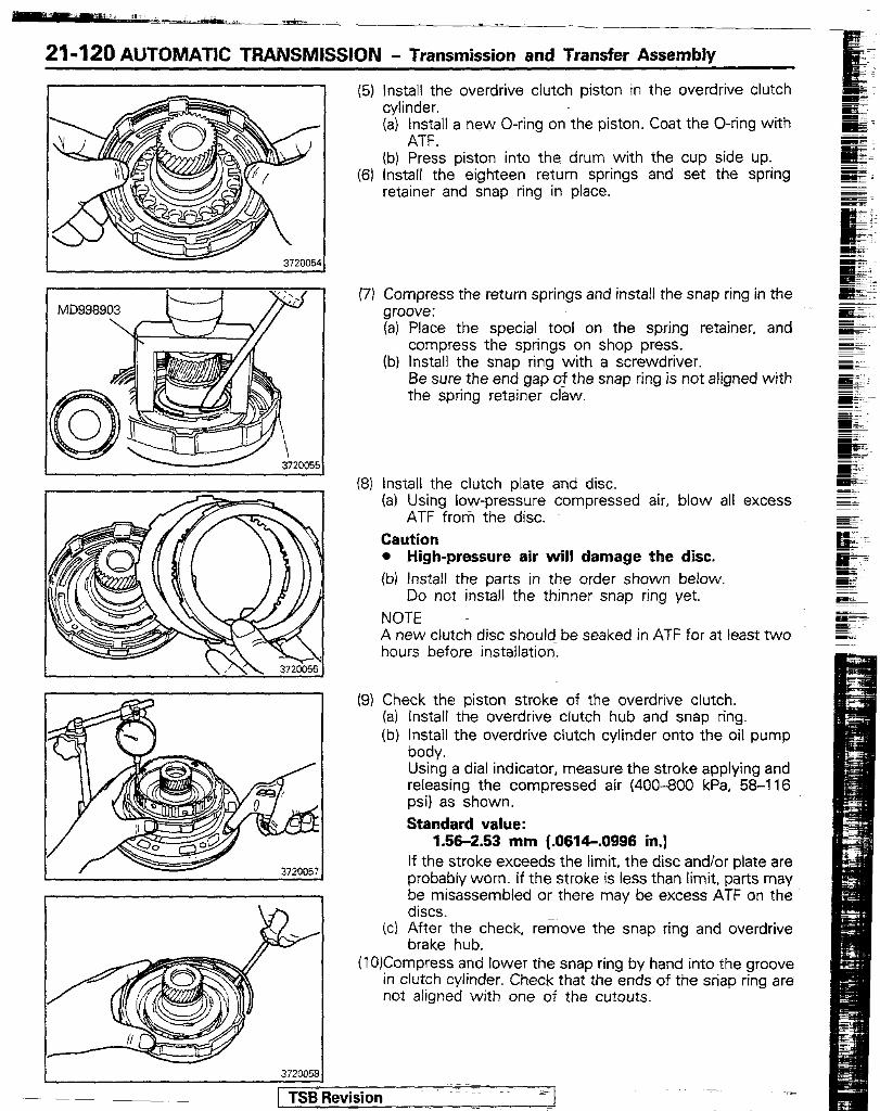
(5) Install the overdrive clutch piston in the overdrive clutch cylinder. (a) Install a new O-ring on the piston. Coat the O-ring with
ATF. (b) Press piston into the drum with the cup side up.
(6) Install the eighteen return springs and set the spring retainer and snap ring in place.
(7) Compress the return springs and install the snap ring in the groove: (a) Place the special tool on the spring retainer, and
compress the springs on shop press. (b) Install the snap ring with a screwdriver.
Be sure the end gap 5i the snap ring is not aligned with the spring retainer claw.
(8) Install the clutch plate and disc. (a) Using low-pressure compressed air, blow all excess
ATF from the disc. Caution l High-pressure air will damage the disc. (b) Install the parts in the order shown below.
Do not install the thinner snap ring yet. NOTE A new clutch disc should- be seaked in ATF for at least two
hours before installation.
(9) Check the piston stroke of the overdrive clutch. (a) Install the overdrive clutch hub and snap ring. (b) ~n;t-~ the overdrive clutch cylinder onto the oil pump
Using a dial indicator, measure the stroke applying and releasing the compressed air (400-800 kPa, 58-l 16 psi) as shown. Standard value:
1.56-2.53 mm (.0614-.0996 in.) If the stroke exceeds the limit, the disc and/or plate are probably worn. If the stroke is less than limit, parts may be misassembled or there may be excess ATF on the discs.
(c) After the check, remove the snap ring and overdrive brake hub.
(I 0)Compress and lower the snap ring by hand into the groove in clutch cylinder. Check that the ends of the snap ring are not aligned with one of the cutouts.

AUTOMATIC TRANSMISSION - Transmission and Transfer Assembly 21-121
3720041
WERDRIVE CASE AND BRAKE MlUAB
(1l)lnstall the overdrive brake hub and snap ring. Check that the ends of the snap ring are not aligned with any of the cutouts.
(12)Assemble the overdrive clutch assembly and overdrive planetary gear assembly while meshing the overdrive brake hub with the disc by twisting or jiggling the hub as required.
(13)Hold the overdrive clutch cylinder and turn the overdrive planetary gear shaft to check the operation of one-way clutch. The shaft should turn freely clockwise and should lock counterclockwise.
Spring retainer Tt~~;earing Snap ring
\ I 1
Seal ring
] TSB Revision
I Brake piston Return spring Overdrive case
3720346
21-122 AUTOMATIC TRANSMISSION - Transmission and Transfer Assembly
DISASSEMBLY (I) Remove the snap ring from the overdrive case. (2) Remove the flange, brake discs, brake plates and cushion
plate. NOTE Do not allow the removed brake discs to dry out.
(3) Remove the planetary ring gear and thrust race #6. (4) Remove the thrust bearing #7 and race #8 from the
overdrive case. Note position of the race-
(5) Remove the snap ring, spring retainer and return springs. (6) Remove the brake piston.
Brow compressed air through the overdrive case hole indicated in the figure to force out the brake piston. if the piston does not come out, lift it out with needle nose plrers.
(7) Remove the two oil seal rings from the overdrive case. (8) Remove the O-rings from the piston.
ASSEMBLY (I) Install the two seal rings on the overdrive case by spreading
apart and sliding them into the groove. Hook both ends by hand.
(2) Install new O-rings on piston. Coat the O-rings with ATF. (3) Install the brake piston in the overdrive case with the cup
side up, being careful not to damage the O-rings. (4) Install the return springs and set the spring retainer and
snap ring in place. -
Check that the ends of the snap ring are not aligned with - any of the cutouts.

AUTOMATIC TRANSMISSION - Transmission and Transfer Assemblv 21-123
Cushion plate -IJM ! I \ 1 372006
(5) Install the thrust bearing #7 and races #6 and #8 to the planetary ring gear and set the ring gear in the overdrive case. NOTE Make sure that the thrust bearing races are installed in the correct direction.
(6) Install the cushion plate. brake discs, brake plates and flange: (a) Using low-pressure compressed air, blow all excess
ATF from the discs (b) Install the parts in the order shown below. NOTE New clutch discs should be soaked in ATF for at least two hours before installation.
Cushion plate (rounded end down) + Brake plate + Brake disc + Brake plate -+ Brake disc + Brake plate -+ Brake disc + Flange (flat end down)
(7) Install the snap ring. Check that the ends of the snap ring are not aligned with one of the cutouts.
(8) Measure the distance between snap ring and flange with feeler gauge to check the brake clearance.
Standard value: 0.65-2.21 mm (.0256-.0870 in.1
(9) Install the thrust washer onto the planetary ring gear.
/ TSB Revision

I. .&L”
21-124 AUTOMATIC TRANSMISSION - Transmission and Transfer Assembly
:ORWARD CLUTCH Nzlumc
Snap ring
Clutch return Snap spring ring
Forward clutch Forward ] Spring ] cylinder I ret?ner I
Clutch disc
~~ I
Thrust be%rmg #12
\ ihrust bearing race #13
Thrust bearing race #l 1
Snap ring (thinner)
Clutch disc
Clutch plate
3720347
DISASSEMBLY (1) Use the extension housing as a work stand. (2) Remove the snap ring from the forward clutch cylinder. (3) Remove the direct clutch hub and forward clutch hub.
(4) Remove the thrust bearing #I2 and the races #I 1 and #13.
(5) Remove the clutch disc. NOTE Do not allow the removed disc to dry out.
(6) Remove the snap ring. (7) Remove the remaining clutch plates and discs.
NOTE Do not allow the removed discs to dry out.
AUTOMATIC TRANSMISSION - Transmission and Transfer Assembly 21-125
720073
u 372,,,1
[ TSB Revision
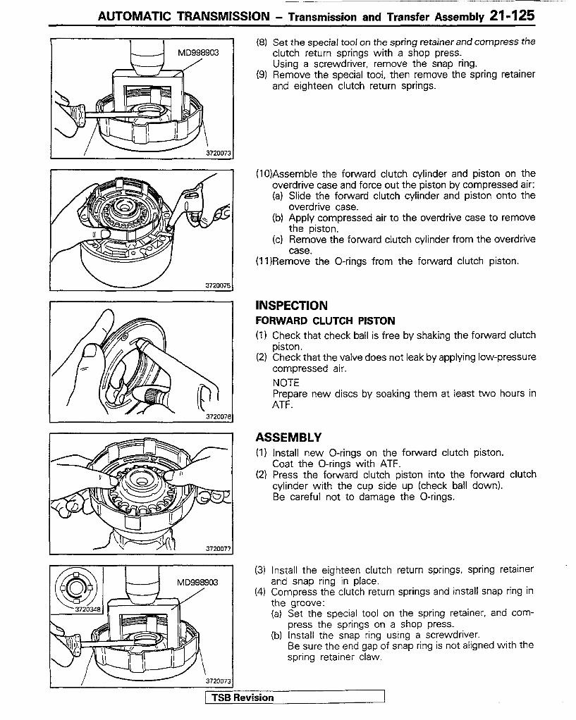
(8) Set the special tool on the spring retainer and compress the clutch return springs with a shop press. Using a screwdriver, remove the snap ring.
(9) Remove the special tool, then remove the spring retainer and eighteen clutch return springs.
(10)Assemble the forward clutch cylinder and piston on the overdrive case and force out the piston by compressed air: (a) Slide the foward clutch cylinder and piston onto the
overdrive case. (b) Apply compressed air to the overdrive case to remove
the piston. (c) Remove the forward clutch cylinder from the overdrive
case. (11 )Remove the O-rings from the forward clutch piston.
INSPECTION FORWARD CLUTCH PISTON (I 1 Check that check ball is free by shaking the forward clutch
piston. (2) Check that the valve does not leak by applying low-pressure
compressed air. NOTE Prepare new discs by soaking them at least two hours in ATF.
ASSEMBLY (I) Install new O-rings on the forward clutch piston.
Coat the O-rings with ATF. (2) Press the forward clutch piston into the forward clutch
cylinder with the cup side up (check ball down). Be careful not to damage the O-rings.
(3) Install the eighteen clutch return springs, spring retainer and snap ring in place.
(4) Compress the clutch return springs and install snap ring in the groove: (a) Set the special tool on the spring retainer, and com-
press the springs on a shop press. (b) Install the snap ring using a screwdriver.
Be sure the end gap of snap ring is not aligned with the spring retainer claw.

21-l 26 AUTOMATIC TRANSMISSION - Transmission and Transfer Assembly
(5) Install the clutch discs and plates without assembling the
I
snap ring. NOTE A new clutch disc should be soaked in ATF for at least two hours before installation. (a) Using low-pressure compressed air, blow all excess -
ATF from discs. mm Caution l High-pressure air will damage discs. lb) Install the clutch plates and discs alternately. Do not
install the snap ring (thinner) yet.
(6) Check the piston stroke of forward clutch: (a) install the direct clutch hub and snap ring. (b) Install the forward clutch cylinder assembly onto the
overdrive case. Using a dial indicator, measure the stroke applying and releasing the compressed air (400-800 kPa. 58-116 psi). Standard stroke: 1.43-2.93 mm (.0563-.I164 in.) If the stroke exceeds the limit, the clutch discs and/or plates are-probably worn. If the stroke is less than the limit, parts may be misassembled or there may be excess ATF on the discs.
(c) After the check, remove the snap ring and direct clutch hub.
(7) Compress and lower the snap ring into the groove by hand. Check that the ends of the snap ring are not aligned with any of the cutouts.
03) Install the clutch disc. -
(9) Install the thrust bearing #I2 and the races #I 1 and #13, all coated with petroleum jelly.
1 TSB Revision
(10)lnstall the forward clutch hub while aligning the disc lugs with the hub teeth. Make sure the hub meshes with all the discs and IS fully inserted.

AUTOMATIC TRANSMlSSlON - Transmission and Transfer Assembly 21-127
(11 )Install the direct clutch hub and snap ring. Check that the snap ring ends are not aligned with any of the cutouts.
DIRECT CLUTCH
Direct Direct clutch cylinder
S ri
Spring’retainer 3720400
DISASSEMBLY (I) Remove the snap ring from the direct clutch cylinder. (2) Remove the flange, clutch discs and plates.
NOTE Do not allow the clutch discs to dry out.
(3) Set the special tool on the spring retainer and compress the piston return springs with shop press. Using snap ring pliers, remove the snap ring.
(4) Remove the spring retainer and eighteen piston return springs.
I I \ 3720085 / TSB Ret&ion

21-128 AUTOMATIC TRANSMlSSlON - Transmission and Transfer Assembly
372008f
372001
~\1?+-+-P MD998903
?
(5) Assemble the direct clutch-cylinder and piston set on the center support and force out the piston by compressed air: (a) Slide the direct clutch cylinder and’piston set onto the
center support. (b) Apply compressed air to the center support to remove
the piston. (c) Remove the direct clutch from the center support.
(6) Remove the O-rings from-the direct clutch piston.
INSPECTION DIRECT CLUTCH PISTON (1) Check that the check ball is free by shaking each piston. (2) Check that the valve does not leak by applying low-pressure
compressed air.
ASSEMBLY (1) Install new O-rings on the direct clutch piston.
Coat the O-rings with ATF. (2) Install the direct clutch piston in the direct clutch cylinder.
To install, press the direct clutch piston into the cylinder with the cup side up, being careful not to damage the O- rings.
(3) install the eighteen piston return springs and set the retainer with snap ring in place.
(4) Compress the piston return springs and install thesnap ring: (a) Set the special tool on the spring retainer, and com-
press the springs on a shop press. (b) With snap ring pliers, install the snap ring.
Be sure the’end gap of the snap ring is not aligned with the spring retainer claw.
(5) Install the clutch discs, plates and flange: NOTE New clutch discs should be soaked in ATF for at least two hours before installation. (a) Using low-pressure compressed air, blow all excess
ATF from the clutch discs. Caution * High-pressure air will damage the discs. (b) Install the parts in the following order:
Clutch plate + Clutch disc -+ Clutch plate -+ Clutch disc 3 Clutch plate + Clutch disc + Flange (flat end down)
1 TSB Revision
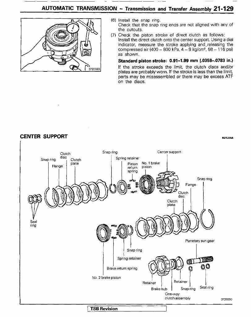
AUTOMATIC TRANSMISSION - Transmission and Transfer Assembly 21-129
Clutch
Clutch plate
I
SnaF
(6) Install the snap ring. Check that the snap ring ends are not aligned with any of the cutouts,
(7) Check the piston stroke of direct clutch as follows: Install the direct clutch onto the center support. Using a dial indicator, measure the stroke applying and. releasing the compressed air (400 - 800 kPa, 4 - 8 kg/cm2, 58 - 116 psi) as shown. Standard piston stroke: 0.91-1.99 mm (.0358-.0783 in.) If the stroke exceeds the limit, the clutch discs and/or plates are probably worn. If the stroke is less than the limit, parts may be misassembled or there may be excess ATF on the discs.
CENTER SUPPORT
1 ring Center suppori
Piston No. 1 brake return Piston
SIl
Flange
lutch ‘SC
Clutch plate
I I
Planetary sun gear I
) ring
Snap ring
Spring retainer
Brake return spring
No. 2 brake piston
1 TSB Revision
One-way clutch assembly
J
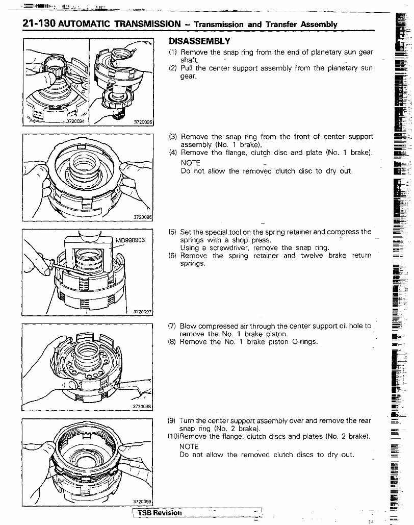
21-130 AUTOMATIC TRANSMISSION - Transmission and Transfer Assemblv
DISASSEMBLY (I)
(21
(3)
(41
(51
(61
(7)
(8)
(9)
Remove the snap ring from the end of planetary sun gear shaft. Pull the center support assembly from the planetary sun gear.
Remove the snap ring from the front of center support assembly (No. 1 brake). Remove the flange, clutch disc and plate (No. 1 brake). NOTE Do not allow the removed clutch disc to dry out.
-
Set the special tool on the spring retainer and compress the springs with a shop press. Using a screwdriver, remove the snap ring. Remove the spring retainer and twelve brake return springs.
Blow compressed air through the center support oil hole to remove the No. 1 brake piston. Remove the No. 1 brake piston O-rings.
Turn the center supportassembly over and remove the rear snap ring (No. 2 brake).
(lOIRemove the flange, clutch discs and plates, (No. 2 brake). NOTE Do not allow the removed clutch discs to dry out.
/ TSB Revision ;I .-
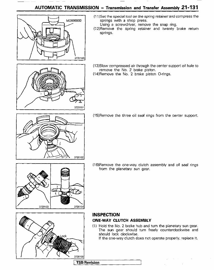
AUTOMATIC TRANSMISSION - Transmission and Transfer Assembly 21-13 1
(11)Set the special tool on the spring retainer and compress the springs with a shop press. Using a screwdriver, remove the snap ring.
(12)Remove the spring retainer and twenty brake return springs.
3720103 372010'
(13)Blow compressed air through the center support oil hole to remove the No. 2 brake piston.
(14)Remove the No. 2 brake piston O-rings.
(15)Remove the three oil seal rings from the center support.
(16)Remove the one-way clutch assembly and oil seal rings from the planetary sun gear.
INSPECTION ONE-WAY CLUTCH ASSEMBLY (1) Hold the No. 2 brake hub and turn the planetary sun gear.
The sun gear should turn freely counterclockwise and should lock clockwise. If the one-way clutch does not operate properly, replace it.
) TSB Revision 1

21-l 32 AUTOMATIC TRANSMISSION - Transmission and Transfer Assembly
3720107 3720108
3720110 1 / 372011
(2) If necessary, replace the one-way clutch: (a) Bend the tabs back with a tapered punch. (b) Pry off the retainer with a screwdriver. Leave the other
retainer on the hub. (c) Remove the one-way clutch.
(d) Install the one-way clutch into the brake hub facing the spring cage toward the front.
(e) Hold the brake hub in vise with soft jaws, and bend the tabs with a chisel.
(f) Check to make sure that the retainer is centered.
ASSEMBLY (I) Install the two seal rings and one-way clutch assembly on
the planetary sun gear.
(2) Install the three seal rings in the groove of center support Hook both ends of ring by hand as shown.
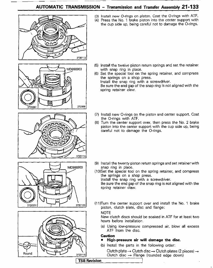
AUTOMATIC TRANSMISSION - Transmission and Transfer Assembly 21- 133
(3) (4)
(5)
(6)
(7)
63)
(9)
Install new O-rings on piston. Coat the O-rings with ATF. Press the No. 1 brake piston into the center support with the cup side up, being careful not to damage the O-rings.
Install the twelve piston return springs and set the retainer with snap ring in place. Set the special tool on the spring retainer, and compress the springs on a shop press. Install the snap ring with a screwdriver. Be sure the end gap of the snap ring is not aligned with the spring retainer claw.
Install new O-rings on the piston and center support. Coat the O-rings with ATF. Turn the center support over, then press the No. 2 brake piston into the center support with the cup side up, being careful not to damage the O-rings.
Install the twenty piston return springs and set retainer with snap ring in place.
(10)Set the special tool on the spring retainer, and compress the springs on a shop press. Install the snap ring with a screwdriver. Be sure the end gap of the snap ring is not aligned with the spring retainer claw.
(11)Turn the center support over and install the No. 1 brake piston, clutch plate, disc and flange: NOTE New clutch discs should be soaked in ATF for at least two hours before installation. (a) Using low-pressure compressed air, blow all excess
ATF from the disc. Caution l High-pressure air will damage the disc. (b) Install the parts in the following order:
Clutch plate + Clutch disc ---) Clutch plates (2 pieces) 3 Clutch disc + Flange (rounded edge down)
) TSB Revision
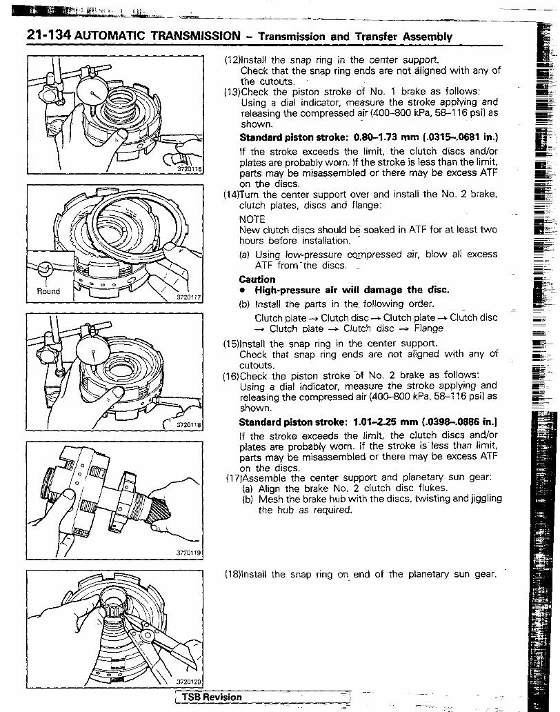
21-134 AUTOMATIC TRANSMISSION - Transmission and Transfer Assembly
(12)lnstall the snap ring in the center support. Check that the snap ring ends are not Sgned with any of the cutouts.
(13)Check the piston stroke of No. 1 brake as follows: Using a dial indicator, measure the stroke applying and releasing the compressed air (400-800 kPa, 56-I 16 psi) as shown. Standard piston stroke: 0.80-1.73 mm (.0315-.0681 in.) If the stroke exceeds the limit, the clutch discs and/or plates are probably worn. If the stroke is less than the limit, parts may be misassembled or there may be excess ATF on the discs.
(14)Turn the center support over and install the No. 2 brake, clutch plates, discs and flange: NOTE New clutch discs should be soaked in ATF for at least two hours before installation. (a) Using low-pressure compressed air, blow all excess
ATF from-the discs. _ Caution l High-pressure air will damage the disc. (b) Install the parts in the following order.
Clutch plate --+ Clutch disc + Clutch plate -+ Clutch disc -+ Clutch plate + Clutch disc -f Flange
(15)lnstall the snap ring in the center support. Check that snap ring ends are not aligned with any of cutouts.
(16)Check the piston stroke %f No. 2 brake as follows: Using a dial indicator, measure the stroke applying and releasing the compressed air (400-800 kPa, 58-l 16 psi) as shown. Standard piston stroke: 1.01-2.25 mm (.0398-.0886 in.) If the stroke exceeds the limit, the clutch discs and/or plates are probably worn. If the stroke is less than limit, parts may be misassembled or there may be excess ATF on the discs.
(17)Assemble the center support and planetary sun gear: (a) Align the brake No. 2 clutch disc flukes. (b) Mesh the brake hub with the discs, twisting and jiggling
the hub as required.
I I/ 3720719
(18)lnstall the snap ring on end of the planetary sun gear.
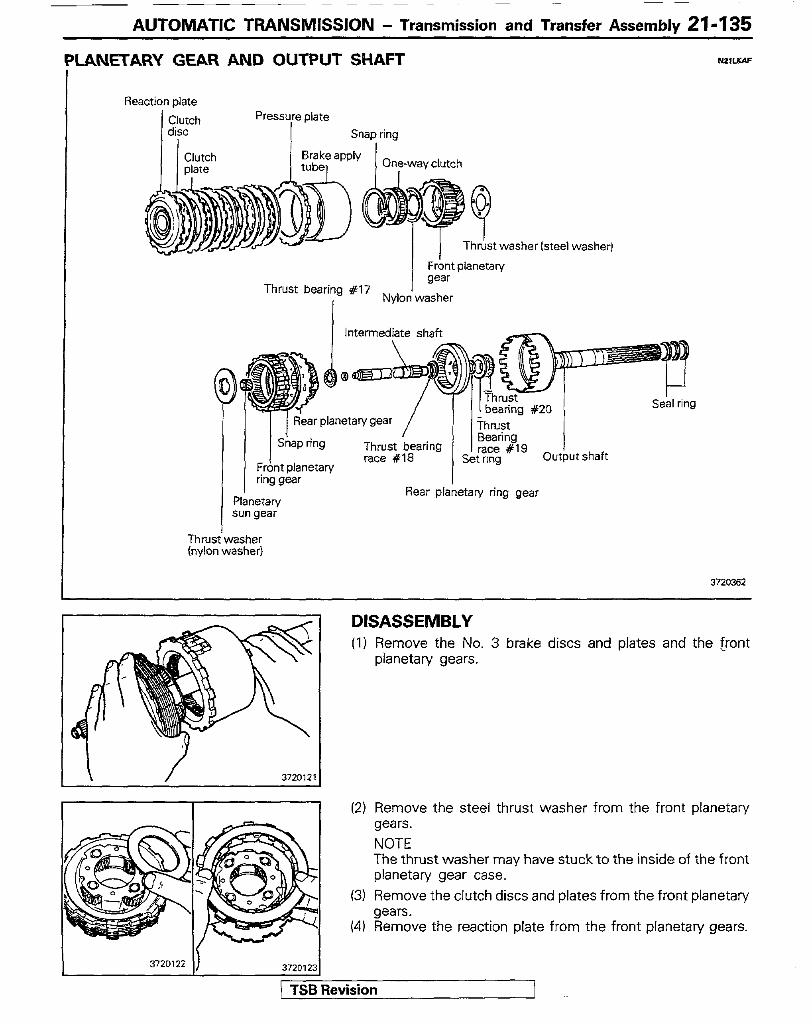
AUTOMATIC TRANSMISSION - Transmission and Transfer Assemblv 21-I 35
LANETARY GEAR AND OUTPUT SHAFT &WXA.=
Reaction plate
Clutch I disc
Pressure plate Snap ring
Thrust washer lsteel washer)
Frbnt planetary
Thrust bearing 117 gear
I Nylon washer
Intermediate shaft
Planetary sun gear
Rear planetary ring gear
Seal ring
Thrusiwasher (nylon washer)
3720362
DISASSEMBLY (1) Remove the No. 3 brake discs and plates and the [rant
planetary gears.
\ / 372012 1
(2) Remove the steel thrust washer from the front planetary gears. NOTE The thrust washer may have stuck to the inside of the front planetary gear case.
(3) Remove the clutch discs and plates from the front planetary gears.
(4) Remove the reaction plate from the front planetary gears.
3720122 3720123
/ TSB Revision

21-136 AUTOMATIC TRANSMISSION - Transmission and Transfer Assembly
.
5
(5) Remove the snap ring and one-way clutch from the front planetary gears.
(6) Remove the nylon washer from the front planetary gears.
I / 372011
(7) Remove the brake apply tube and pressure plate. (8) Compress the snap ring and remove the front planetary ring
gear: (a) While pulling up the ring gear, compress the snap ring
with needle-nose pliers and remove it from the groove. (b) Pull out the front planetary ring gear by hand.
(9) Remove the intermediate shaft assembly from the output shaft.
(lO)Remove the thrust bearing #20 and race #19 from the output shaft.
(ll)Remove the three seal rings from the ouput shaft.
(12)Remove the nylon thrust washer from the rear planetary gear.
(13)Remove the planetary sun gear. (14)Remove the rear planetary gear from the intermediate shaft
assembly. (15)Remove the thrust bearing #I7 from the intermediate
shaft. Note the position of the races.
(16)lnvert the intermediate shaft and remove the set ring. (17)Remove the rear plan&ary ring gear and thrust bearing
race #I8 from the intermediate shaft. Note the position of the race.

AUTOMATIC TRANSMISSION - Transmission and Transfer Assembly 21-137
ASSEMBLY (I) Install the thrust bearing race #I8 and rear planetary ring
gear on the intermediate shaft as follows: Slip the thrust bearing race and ring gear onto the intermediate shaft with the exterior splines up, as shown,
(2) Install the set ring on the intermediate shaft. Make sure the rear planetary ring gear is secure on the intermediate shaft.
(3) ply over the intermediate shaft and install thrust bearing
(4) Install the pinion gear assembly and nylon thrust washer on the rear planetary carrier. Install the washer with the lugs down, fitting them into the rear planetary gear carrier. Caution l Make sure the different lug shapes match the
openings on the plate.
(5) Install the three oil seal rings on the output shaft by spreading apart and sliding them into the groove. Hook both ends by hand.
(6) Use the extension housing as an assembly stand. (7) Install the thrust bearing #20 and race #I9 on the output
shaft.
(8) Install the intermediate shaft assembly in the output shaft. (9) Install the rear planetary gear in the output shaft. (10)lnstall the planetary sun gear in the rear planetary gear.
( TSB Revision 1
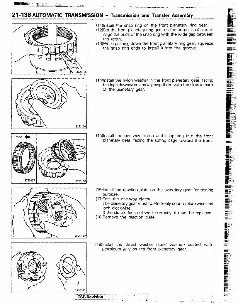
:i ffz i .. , / il.
21-138 AUTOMATIC TFlANSMlSSlON - Transmission and Transfer Assembly
37201x
I I
(1l)lnstall the snap ring on the front planetary ring gear. (12)Set the front planetary ringgear on the output shaft drum.
Align the ends-of the snap ring with the wide gap between the teeth.
(13)While pushing down the front planetary ring gear, squeeze the snap ring ends to install it into the groove.
(14)lnstall the nylon washer in the front planetary gear. facing the lugs downward and aligning them with the slots in back of the planetary gear.
(15)lnstall the one-way clutch and snap ring into the front planetary gear, facing the spring cage toward the front.
(16)lnstali the reaction plate on the planetary gear for testing purpose.
(17)Test the one-way clutch. The planetary gear must rotate freely counterclockwise and lock clockwise. If the clutch does not work correctly, it must be replaced.
(18)Remove the reaction plate.
(19llnstall the thrust washer (steel washer) coated with petroleum jelly on the front planetary gear.
1 TSB Revision ~-~- 1 - -
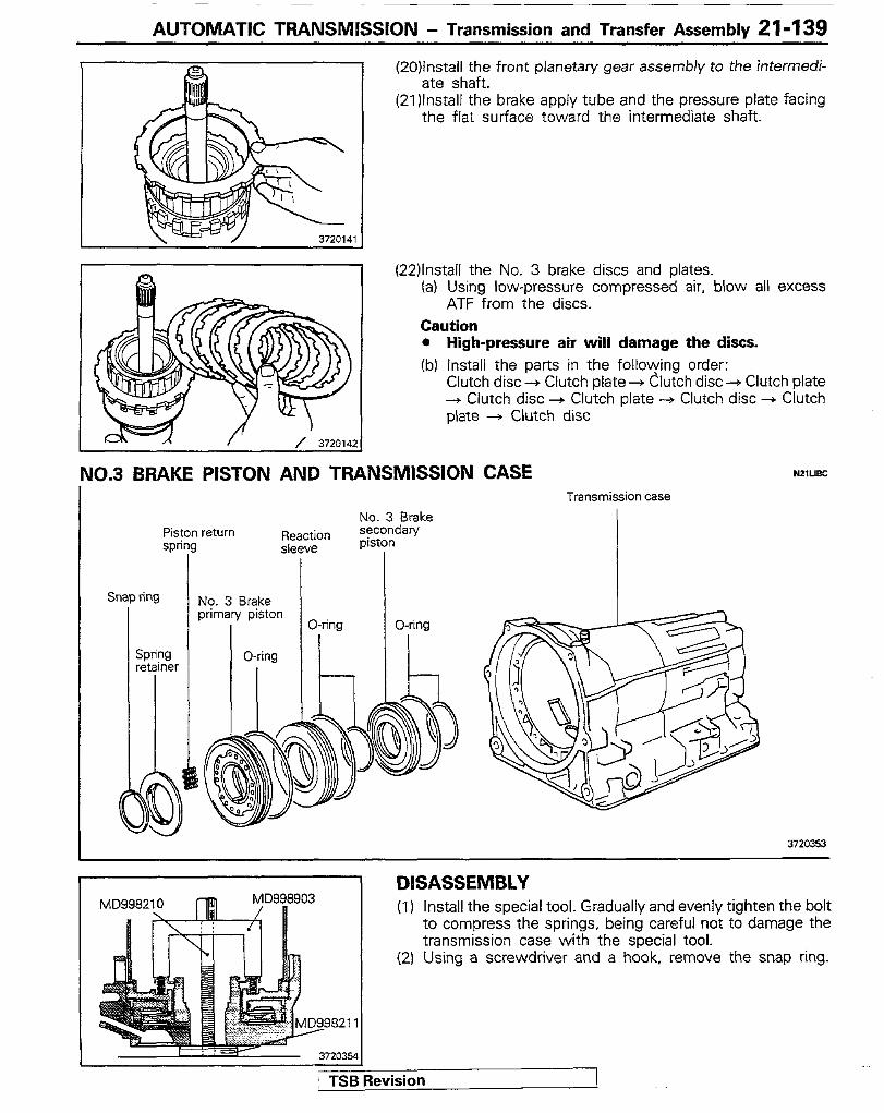
AUTOMATIC TRANSMISSION - Transmission and Transfer Assembly 21-139
(20)lnstall the front planetary gear assembly to the intermedi- ate shaft.
(2l)lnstall the brake apply tube and the pressure plate facing the flat surface toward the intermediate shaft.
(22)lnstaii the No. 3 brake discs and plates. (a) Using low-pressure compressed air, blow all excess
ATF from the discs. Caution l High-pressure air will damage the discs. (b) install the parts in the following order:
Clutch disc -+ Clutch plate + Clutch disc -+ Clutch plate + Clutch disc + Clutch plate -+ Clutch disc + Clutch plate -+ Clutch disc
NO.3 BRAKE PISTON AND TRANSMISSION CASE NmJac
Pis w
Snap ring
ton ing
spring stainer
return
Transmission case No. 3 Brake
f,Fe;F secondary piston I
No. 3 Brake priman/ piston
O-ring
O-ring O-ring
3720353
DISASSEMBLY (1) Install the special tool. Gradually and evenly tighten the bolt
to compress the springs, being careful not to damage the transmission case with the special tool.
(2) Using a screwdriver and a hook, remove the snap ring.
;evision

21-140 AUTOMATIC TRANSMISSION - Transmission and Transfer Assembly
\ \ / 372014
(3) Remove the spring retainer and sixteen piston return springs.
(4) With the frontend down, place the transmission case on a workbench. Place several clean shop rags under the case to catch the piston and sleeve. Apply compressed air to the primaty and secondary piston oil holes to force the piston and sleeve out.
(5) If the piston and sleeve do not come out with the compressed air: (a) Using needle-nose pliers, lift the primary piston from
the case.
(b) insert two long hooks behind the reaction sleeve and gradually lift it out of the case.
(c) Using hooks, lift the secondaty piston out of case in the same manner.
(6) Remove the O-rings from the primary and secondary pistons and the reaction sleeve.
PSI3 Revision I
REPLACEMENT OF MANUAL SHAFT OIL SEALS (1) Remove the manual shaft oi! seals with a screwdriver. (2) Drive in new left and right oil seals with a socket wrench.
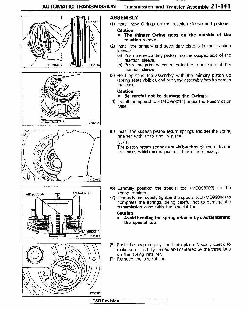
AUTOMATIC TRANSMISSION - Transmission and Transfer Assemblv 21-141
ASSEMBLY (1‘) Install new O-rings on the reaction sleeve and pistons.
Caution l The thinner O-ring goes on the outside of the
reaction sleeve. (2) Install the primary and secondary pistons in the reaction
sleeve: (a) Push the secondary piston into the cupped side of the
reaction sleeve. (b) Push the primary piston onto the other side of the
reaction sleeve. (3) Hold by hand the assembly with the primary piston up
(spring seats visible). and push the assembly into its bore in the case. Caution l Be careful not to damage the O-rings.
(4) Install the special tool (MD99821 1) under the transmission case.
(5) install the sixteen piston return springs and set the spring retainer with snap ring in place. NOTE The piston return springs are visible through the cutout in the case, which helps position them more easily.
(6) Carefully position the special tool (MD998903) on the spring retainer.
(7) Gradually and evenly tighten the special tool (MD99804) to compress the springs, being careful not to damage the transmission case with the special tool. Caution l Avoid bending the spring retainer by ovettightening
the special tool.
(8) Push the snap ring by hand into place. Visually check to make sure it is fully seated and centered by the three lugs on the spring retainer.
(9) Remove the special tool.
w Revision 1
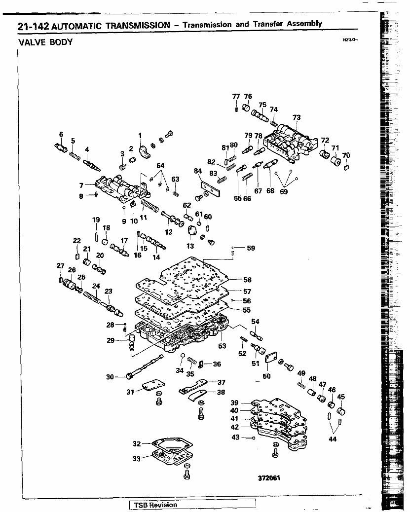
21-142 AUTOMATIC TRANSMISSION - Transmission and Transfer Assembly
VALVE BODY NmLo-
1 TSB Revision 1
77 76
73
72
Q
6

AUTOMATIC TRANSMISSION - Transmission and Transfer Assembly 21-143
1. Throttle cam 43. Check valve 2. Cam spacer 44. Locating pin 3. Return spring 45. Manual plug 4. Throttle valve 46. Third coast shift valve plug 5. Throttle valve primary spring 47. Third coast shift valve 6. Kickdown valve 48. 34 shift control valve 7. Upper front vahre body 49. 3-4 shift control valve spring 8. Check valve 50. Low coast shift valve cover 9. Check ball 51. Low coast shift valve
10. Throttle valve keep plate 52. I-2 shift valve spring 11. Secondan/ regulator valve spring 53. Lower valve body 12. Secondary regulator valve 54. Plug 13. Front valve end cover 55. Lower valve body gasket 14. l-2 shii valve 56. Check valve 15. l-2 shift valve plug 57. Separate plate 16. Valve retainer 58. Valve body gasket 17. 34 shift valve 59. Check valve 18. 3-4 shift valve plug 60. Valve retainer 19. Locating pin 61. Cut back plug 20. D-2 down timing valve 62. Cut back valve 21. D-2 down timing valve plug 63. Throttle valve secondary spring 22. Valve retainer 64. E-ring 23. Primary regulator valve 65. Reverse brake sequence valve 24. Primary regulator valve spring 66. Low coast modulator valve spring 25. Primary regulator valve plungef 67. Plug 26. Primary regulator valve sleeve 68. Low coast modulator valve 27. Valve retainer 69. Check valve 28. Check valve 70. Valve retainer 29.’ Check valve 71. Intermediate coast shift valve plug 30. Manual valve 72. Intermediate coast shift valve 31. Plate 73. Upper rear valve body 32. Oil screen gasket 74. 2-3 shift valve spring 33. Oil screen 75. 23 shift valve 34. Pressure relief valve 76. 2-3 shift valve plug 35. Pressure relief valve spring 77. Valve retainer 36. Retainer 78. Intermediate coast modulator valve 37. Detent spring 79. Detent regulator valve 38. Detent spring plate 80. Detent regulator valve spring 39. Lower valve body cover gasket (upper) 81. Valve retainer 40. Lower valve body cover plate 82. intermediate coast modulator valve spring 41. Lower valve body cover gasket flower) 83. Reverse clutch sequence valve spring 42. Lower valve body cover 84. Rear valve cover
1 TSB Revision

21-144 AUTOMATIC TRANSMISSION - Transmission and Transfer Assembly
DISASSEMBLY For disassembly, observe the precautions given below. (1) Keep the disassembled parts orderly for efficient reassembly
operation. Attach tags to springs for identification. (2) When disassembling the valve, do not attempt to remove the
valve with undue force. The valve and valve hole could be damaged or burred, leading to faulty valve operation.
(3) When removing the front upper and rear valve bodies from the lower valve body, use care not to lose check balls and springs.
INSPECTlON Wash the removed parts and dry with air. Then, make the follow ing checks.
Caution When making checks, usa care not to damage valve land out- side and valve body holes.
(1) Check the valves for damage and wear. (2) Insert the valves in the valve body and check smooth rotation
and sliding. (3) Check the valve body for damage and wear of valve hole bores
and for clogging of oil holes and oil ways. (4) Check for damage of the valve body plate wear and damage of
check balls. (5) Check for clogging of the oil strainer.
Kick-d&n valve Secondary regulator valve
388181
) TSB f&vision .-
- _-
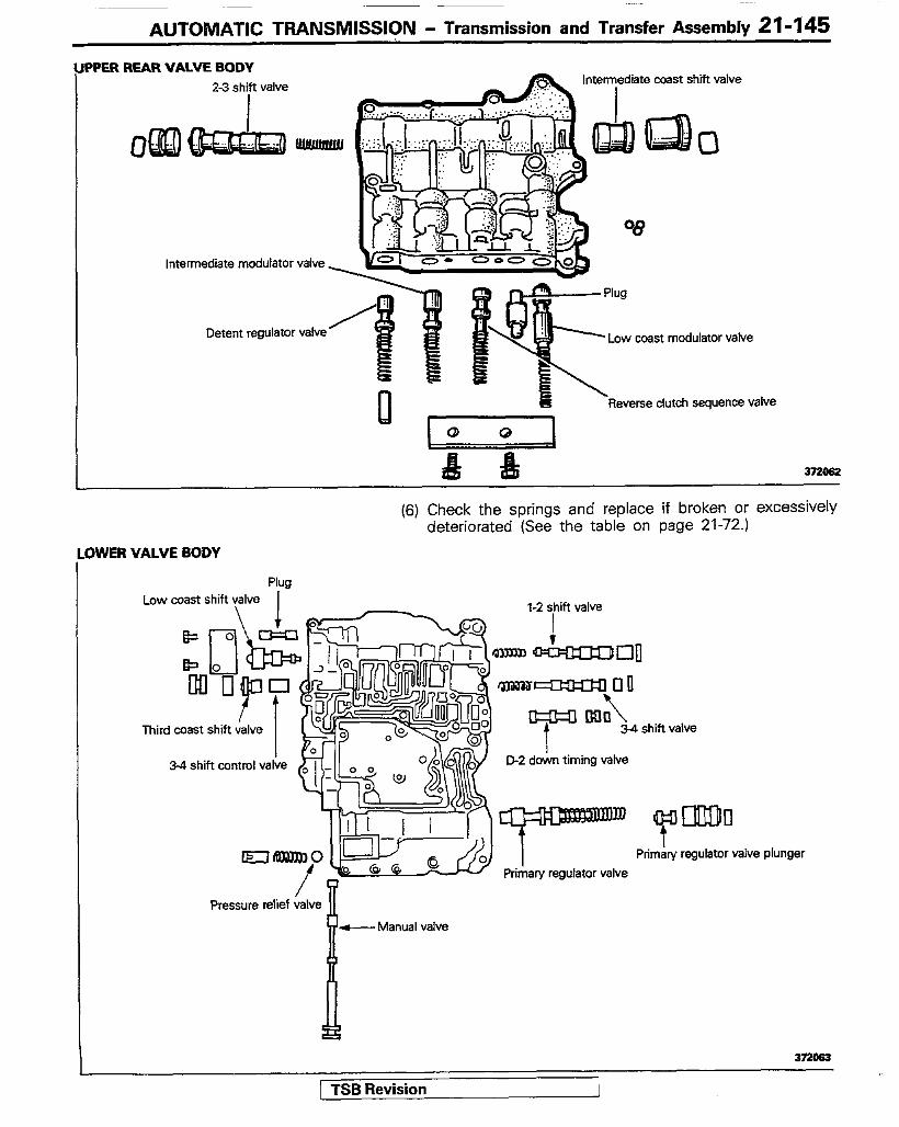
AUTOMATIC TRANSMISSION - Transmission and Transfer Assembly 21-145
REAR VALVE BODY
2-3 shift valve intermediate coast shift valve
I I
&QgQ&J (g&g*
Intermediate modulator valve
Detent regulator valve Low coast modulator valve
Reverse clutch sequence valve
373oa3
34 shift control valve
c II ,I - -I (..I 4 t EltlBllD0 Primary regulator valve
/ Pressure relief valve
I
e
+--Manual valve
(6) Check the springs and replace if broken or excessively deteriorated (See the table on page 21-72.)
3WER VALVE BODY
Plug Low coast shift valve
l-2 yhift valve
I+
“WI
Third coast shift valve
D-2 down timing valve
373063
1 TSB Revision
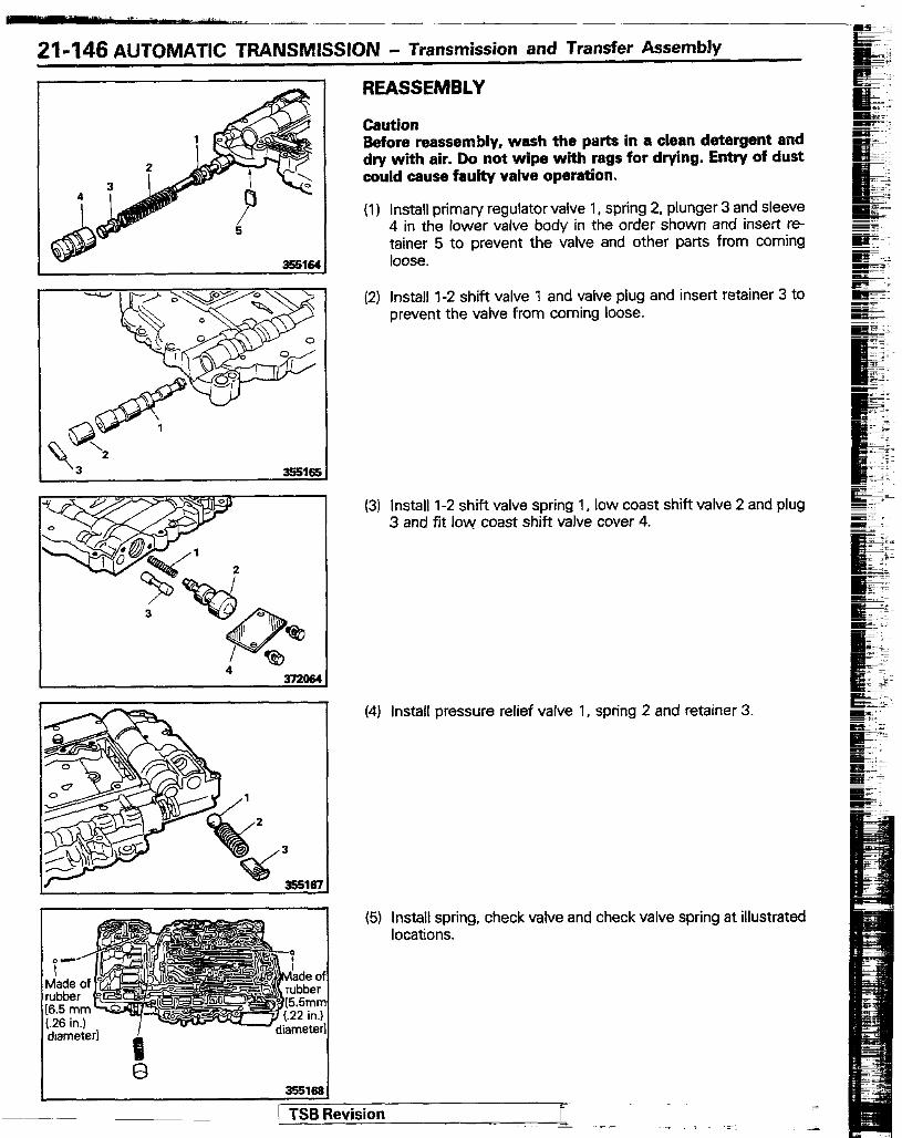
21-146 AUTOMATIC TRANSMISSION - Transmission and Transfer Assembly
3551Sl
I 4 372&a
REASSEMBLY
Caution Before reassembly, wash the parts in a clean detergent and dry with air. Do not wipe with rags for drying. Entry of dust could cause faulty vahfe operation.
(1) Install primary regulator valve 1, spring 2, plunger 3 and sleeve 4 in the lower valve body in the order shown and insert re- tainer 5 to prevent the valve and other parts from coming loose.
(2) Install 1-2 shift valve 1 and valve plug and insert retainer 3 to prevent the valve from coming loose.
(3) install l-2 shift valve spring 1, low coast shift valve 2 and plug 3 and fit low coast shift valve cover 4.
(4) Install pressure relief valve 1, spring 2 and retainer 3.
(5) install spring, check valve and check valve spring at illustrated locations.
3!%1681
( TSB Revision
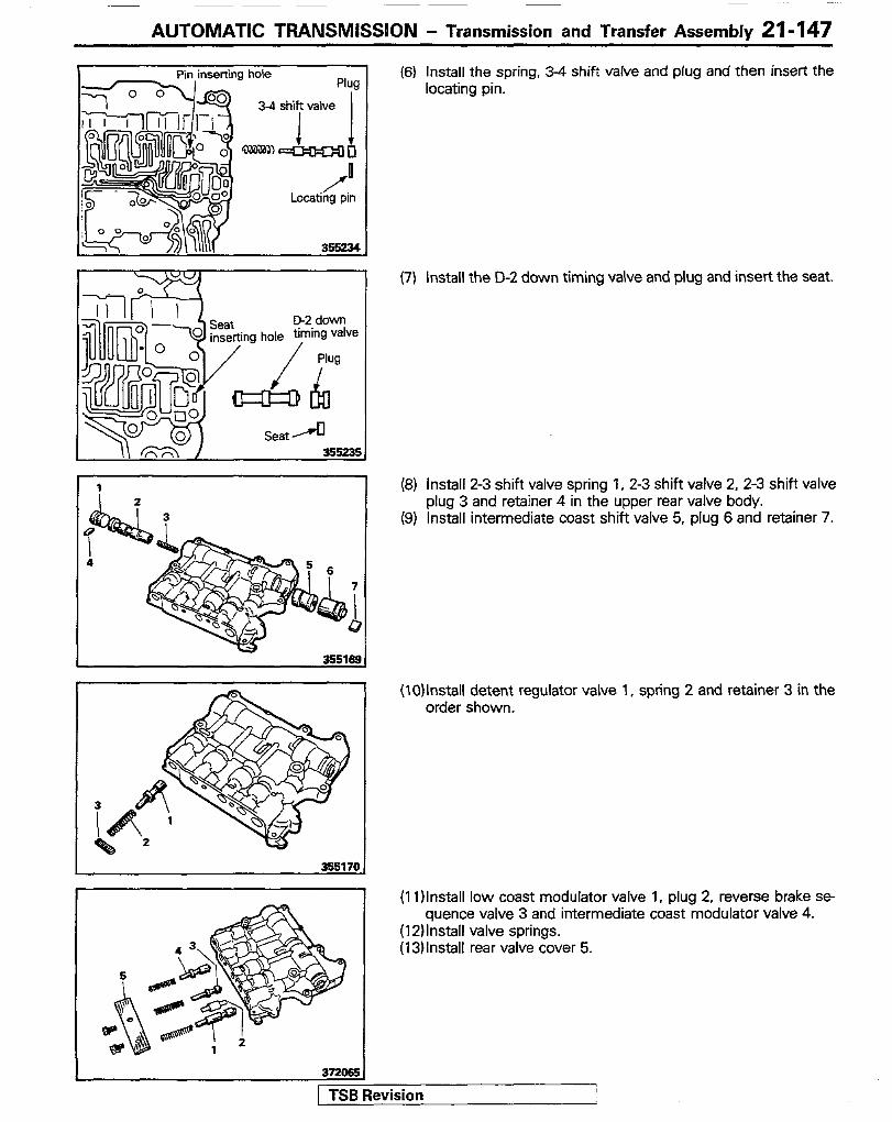
AUTOMATIC TRANSMISSION - Transmission and Transfer Assembly 21-147
35517c
(6) install the spring, 3-4 shift valve and plug and then insert the locating pin.
(7) install the D-2 down timing valve and plug and insert the seat.
(8) install 2-3 shift valve spring 1, 2-3 shift valve 2, 2-3 shift valve plug 3 and retainer 4 in the upper rear valve body.
(9) Install intermediate coast shift valve 5. plug 6 and retainer 7.
(10)lnstall detent regulator valve 1, spring 2 and retainer 3 in the order shown.
(11 )Install low coast modulator valve 1, plug 2, reverse brake se- quence valve 3 and intermediate coast modulator valve 4.
(12)lnstall valve springs. (13)lnstall rear valve cover 5.
avision I
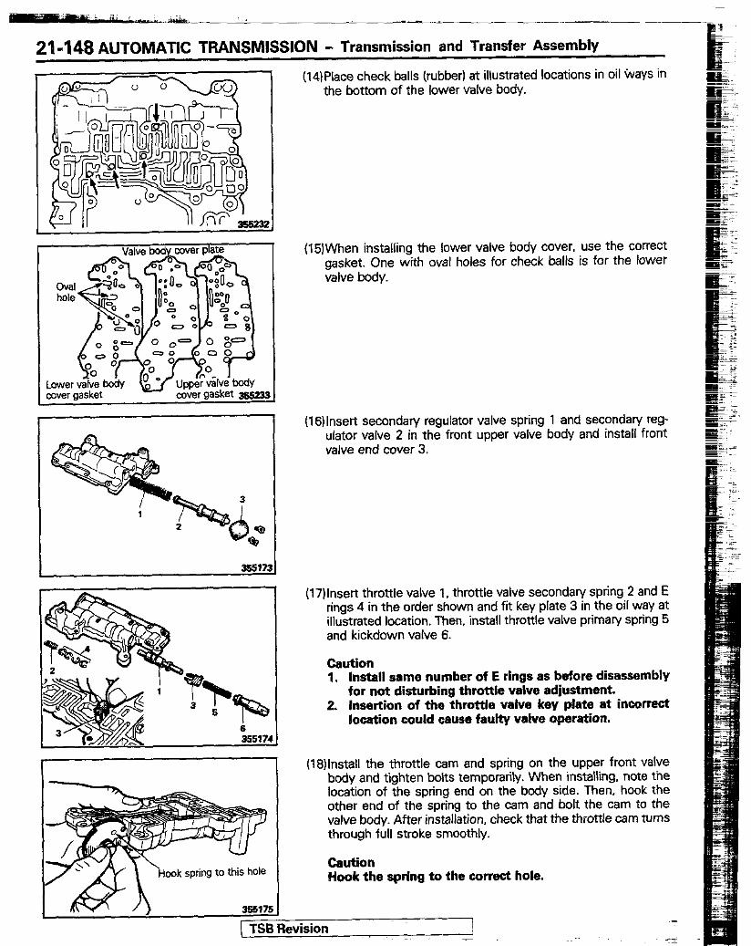
21-148 AUTOMATIC TRANSMISSION - Transmission and Transfer Assembly
(14)Place check balls (rubber) at illustrated locations in oil ways in the bottom of the lower valve body.
(15)When installing the lower valve body cover, use the correct gasket. One with oval holes for check balls is for the lower valve body.
ook spring to this hole
(16)lnser-t secondary regulator valve spring 1 and secondan/ reg- ulator valve 2 in the front upper valve body and install front valve end cover 3.
(17)lnser-t throttle valve 1. throttle valve secondary spring 2 and E rings 4 in the order shown and fit key plate 3 in the oil way at illustrated location. Then, install throttle valve primary spring 5 and kickdown valve 6.
Caution 1. Install sama number of E rings as before disassembly
for not disturbing throttle valve adjustment. 2. Insertion of the throttle valve key plate at incorrect
location could cause faulty valve operation.
(18)lnstall the throttle cam and spring on the upper front valve body and tighten bolts temporarily. When installing, note the location of the spring end on the body side. Then, hook the other end of the spring to the cam and bolt the cam to the valve body. After installation, check that the throttle cam turns through full stroke smoothly.
Caution Hook the spring to the correct hole.
1 TSB Revision
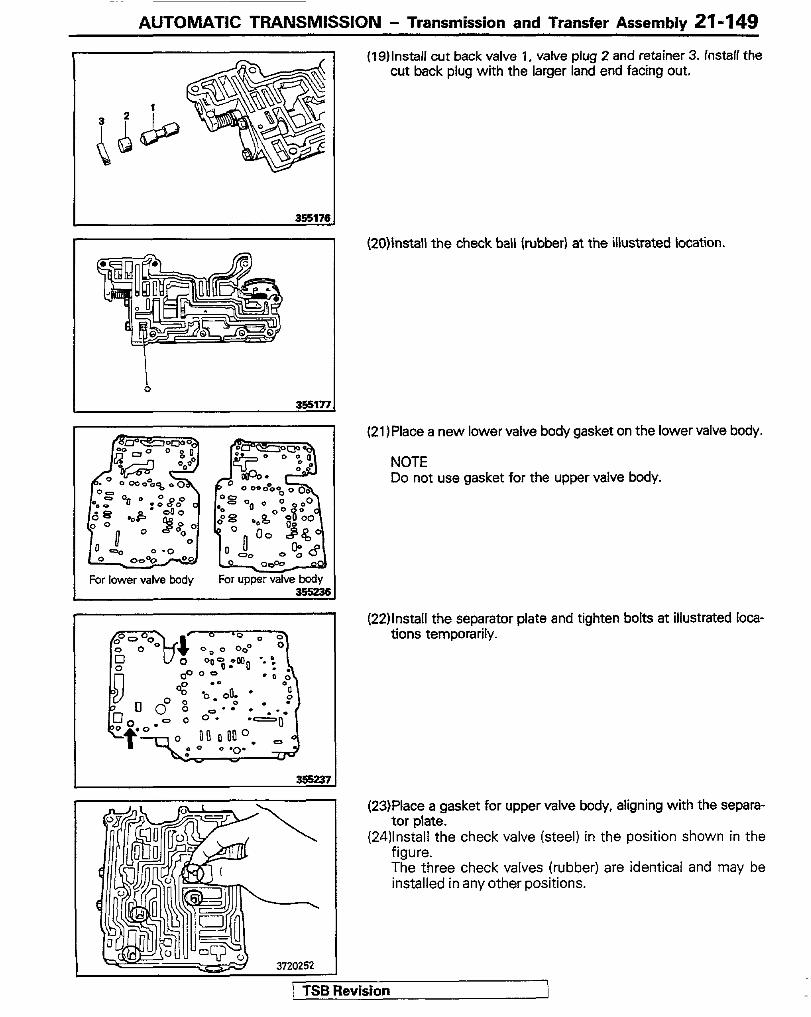
AUTOMATIC TRANSMISSION - Transmission and Transfer Assembly 21-149
I 355171
For lower valve body
I
(19)lnstall cut back valve 1, valve plug 2 and retainer 3. fnstalf the cut back plug with the larger land end facing out.
(20)install the check ball (rubber) at the illustrated location.
(21 IPlace a new lower valve body gasket on the lower valve body.
NOTE Do not use gasket for the upper valve body.
(22)lnstall the separator plate and tighten bolts at illustrated loca- tions temporarily.
(23)Place a gasket for upper valve body, aligning with the separa- tor plate.
(24)lnstall the check valve (steel) in the position shown in the figure. The three check valves (rubber) are identical and may be installed in any other positions.
1 TSB Revision
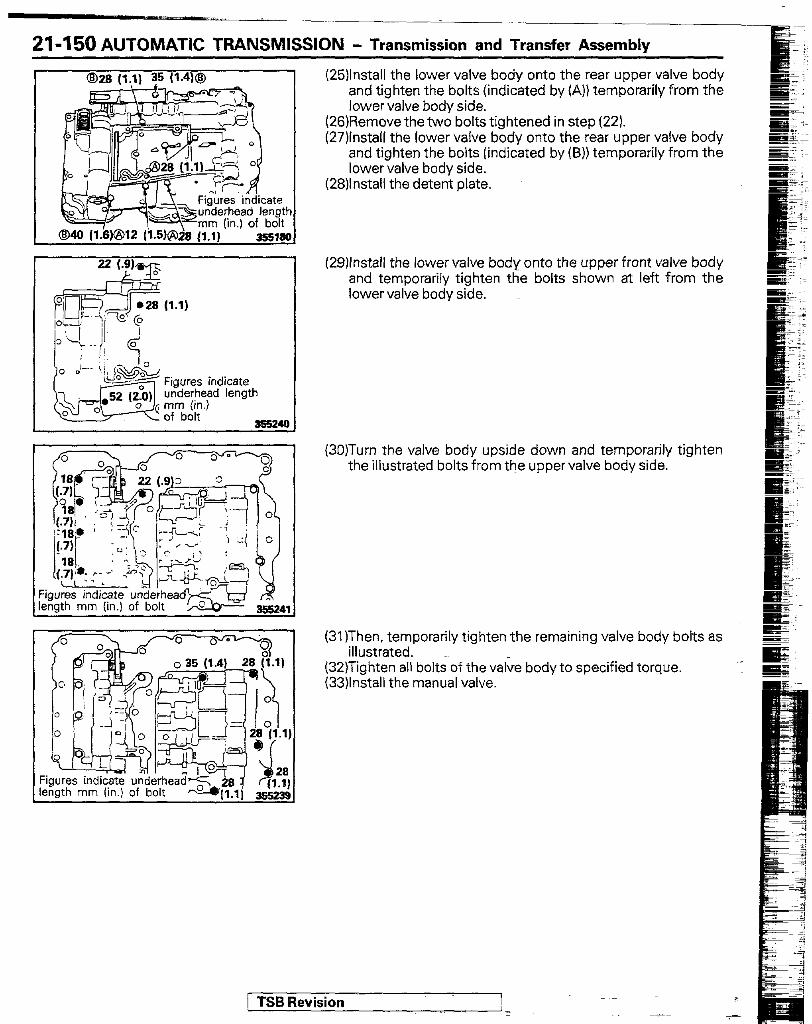
21-q 50 AUTOMATIC TRANSMISSION - Transmission and Transfer Assemblv
Fi le
(25)lnstall the lower valve body onto the rear upper valve body and tighten the bolts (indicated by (A)) temporarily from the lower valve body side.
(26)Remove the two bolts tightened in step (22). (27)lnstall the lower valve body onto the rear upper valve body
and tighten the bolts (indicated by(B)) temporarily from the lower valve body side.
(28)lnstall the detent plate.
(29)lnstall the lower valve body onto the upper front valve body and temporarily tighten the bolts shown at left from the lower valve body side.
(3O)Turn the valve body upside down and temporarily tighten the illustrated bolts from the upper valve body side.
(31)Then. temporarily tighten the remaining valve body bolts as illustrated.
(32)Tighten all bolts of the valve body to specified torque. (33)lnstall the manual valve.
1 TSB Revision

AUTOMATIC TRANSMISSION - Transmission and Transfer Assembly 21-151
GOVERNOR
Outer governor spring
Inner governor spring
JJ- Secondary we&t
Governor valve shaft
Governor retaining ring
Lock plate
3720265
DISASSEMBLY (I) Compress the spring by pushing up on the governor valve
shaft and down on the governor weight. Remove the E-ring with a screwdriver. Lift off the governor weight.
(2) Remove the governor valve by letting it down through the bore.
(3) Remove the governor retaining ring. To remove, disengage the end indicated by an arrow, being careful not to scratch the governor body.
1 TSB Revision
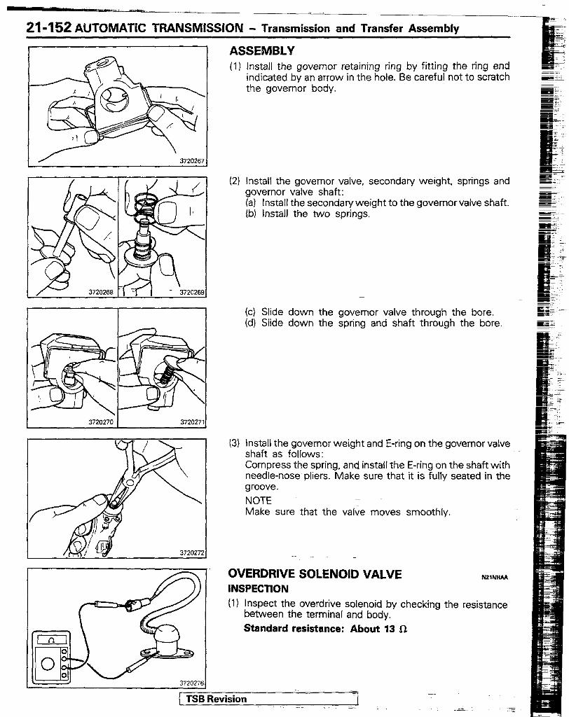
21-152 AUTOMATIC TRANSMISSION - Transmission and Transfer Assembly
I 3720270 1 3720271
ASSEMBLY (1) Install the governor retaining ring by fitting the ring end
indicated by an arrow in the hole. Be careful not to scratch the governor body.
(2) install the governor valve, secondary weight. springs and governor valve shaft: (a) install the secondaryweight to the governor valve shaft. (b) Install the two springs.
(c) Slide down the governor valve through the bore. (d) Slide down the spring and shaft through the bore.
(3) Install the governor weight and E-ring on the governor valve shaft as follows: Compress the spring, and install the E-ring on the shaft with needle-nose pliers. Make sure that it is fully seated in the groove. NOTE Make sure that the valve moves smoothly.
OVERDRIVE SOLENOID VALVE NZINWA INSPECTiON (I) Inspect the overdrive solenoid by checking the resistance
between the terminal and body. Standard resistance: About 13 SI
Sevision I
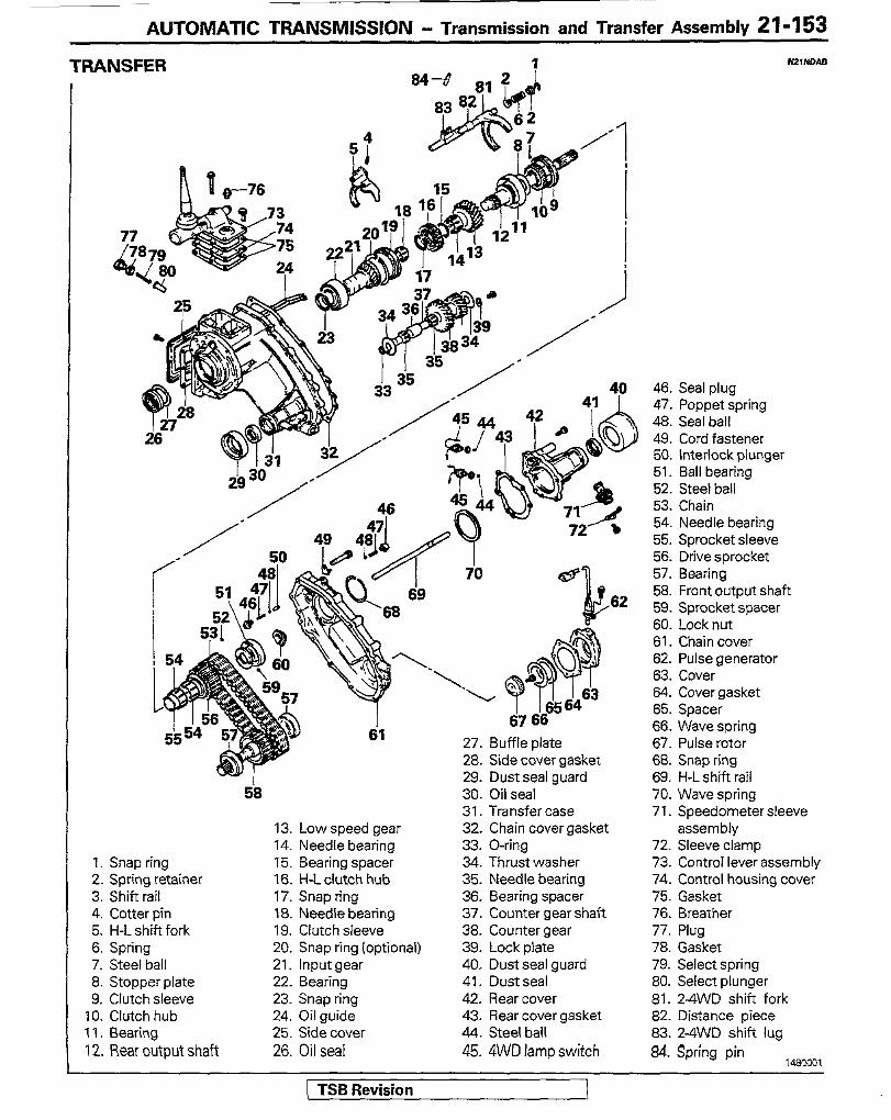
AUTOMATIC TRANSMISSION - Transmission and Transfer Assembly 21-153
IXANSFER
h t w-76
I 61 27. Buff le plate
28. Side cover gasket 29. Dust seal guard
58
1. Snap ring 2. Spring retainer 3. Shift rail 4. Cotter pin 5. H-L shift fork 6. Spring 7. Steel ball 8. Stopper plate 9. Clutch sleeve
10. Clutch hub 11. Bearing 12. Rear output shaft
13. Low speed gear 14. Needle bearing 15. Bearing spacer 16. H-L clutch hub 17. Snap ring 18. Needle bearing 19. Clutch sleeve 20. Snap ring (optional) 21. Input gear 22. Bearing 23. Snap ring 24. Oil guide 25. Side cover 26. Oil seal
- 30. Oil seal 31. Transfer case 32. Chain cover gasket 33. O-ring 34. Thrust washer 35. Needle bearing 36. Bearing spacer 37. Counter gear shaft 38. Counter gear 39. Lock plate 40. Dust seal guard 41. Dust seal 42. Rear cover 43. Rear cover gasket 44. Steel ball 45. 4WD lamp switch
46. Seal plug 47. Poppet spring 4% Seal ball 49. Cord fastener 50. Interlock plunger 51. Ball bearing 52. Steel ball 53. Chain 54. Needle bearing 55. Sprocket sleeve 56. Drive sprocket 57. Bearing 58. Front output shaft 59. Sprocket spacer 60. Lock nut 61. Chain cover 62. Pulse generator 63. Cover 64. Cover gasket 65. Spacer 66. Wave spring 67. Pulse rotor 68. Snap ring 69. H-L shift rail 70. Wave spring 71. Speedometer sleeve
assembly 72. Sleeve clamp 73. ControT lever assembly 74. Control housing cover 75. Gasket 76. Breather 77. Plug 78. Gasket 79. Select spring 80. Select plunger 81. 2-4WD shift fork 82. Distance piece 83. 2-4WD shift lug &I. Spring pin
1480001
( TSB Revision
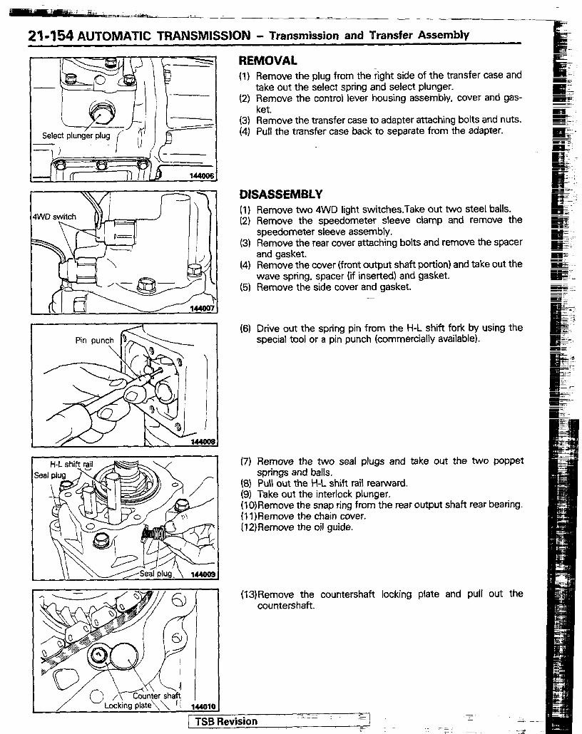
21-154 AUTONIATIC TRANSNIISSION - Transmission and Transfer Assembly
4WD switch
-
I
REMOVAL (I) Remove the plug from the right side of the transfer case and
take out the select spring and select plunger. (2) Fitmove the control lever housing assembly, cover and gas-
(3) Remove the transfer case to adapter attaching bolts and nuts. (4) Pull the transfer case back to separate from the adapter.
DISASSEMBLY (1) Remove two 4WD light switches.Take out two steel balls. (2) Remove the speedometer sleeve clamp and remove the
speedometer sleeve assembly. (3) Remove the rear cover attaching bolts and remove the spacer
and gasket. (4) Remove the cover (front output shaft portion) and take out the
wave spring, spacer (if inserted) and gasket. (5) Remove the side cover and gasket.
(6) Drive out the spring pin from the H-L shift fork by using the special tool or a pin punch (commercially available).
(7) Remove the two seal plugs and take out the two poppet
3) Pull out the H-L shift rail rearward.
I’ 3) Take out the interlock plunger. IO)Remove the snap ring from the rear output shaft rear bearing. I l)Remove the chain cover. I2)Remove the oil guide.
springs and balls.
(13)Remove the countershaft locking plate and pull out the countershaft.
1 TSB Revision- - IIIIz$l
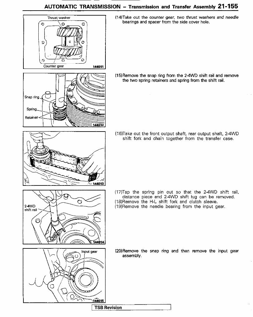
AUTOMATIC TRANSMISSION - Transmission and Transfer Assemblv 21-I 55
Thrust washer
I / Counter aear
(14)Take out the counter gear, two thrust washers and needle bearings and spacer from the side cover hole.
(15)Remove the snap ring from the 2-4WD shift rail and remove the two spring retainers and spring from the shift rail.
(16)Take out the front output shaft, rear output shaft, 24WD shift fork and chain together from the transfer case.
(17)Tap the spring pin out so that the 2-4WD shift rail, distance piece and 24WD shift lug can be removed.
(18)Remove the H-L shift fork and clutch sleeve. (19)Remove the needle bearing from the input gear.
(20)Remove the snap ring and then remove the input gear assembly.
1 TSB Revision
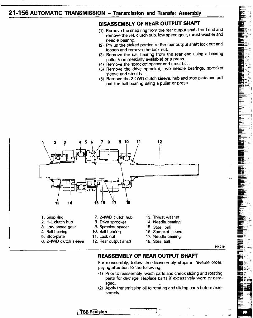
21-156 AUTOMATIC TRANSMISSION - Transmission and Transfer Assembly
DISASSEMBLY OF REAR OUTPUT SHAFT (1) Remove the snap ring from the rear output shaft front end and
remove the H-L clutch hub, low speed gear, thrust washer and needle bearing.
(2) Pry up the staked portion o? the rear output shaft lock nut and loosen and remove the lock nut.
(3) Remove the ball bearing from the rear end using a bearing puller (commercially available) or a press.
(4) Remove the sprocket spacer and steel ball. (5) Remove the drive sprocket, two needle bearings, sprocket
sleeve and steel ball. (6) Remove the 2-4WD clutch sleeve, hub and stop plate and pull
out the ball bearing using a puller or press.
123 456 76 9 10 11
1. Snap ring 7. 2-4WD clutch hub 2. H-L clutch hub 8. Drive sprocket 3. Low speed gear 9. Sprocket spacer 4. Ball bearing 10. Ball bearing 5. Stop-plate 11. Lock nut 6. 2-4WD clutch sleeve 12. Rear output shaft
13. Thrust washer 14. Needle bearing 15. Steel ball 16. Sprocket sleeve 17. Needle bearing 18. Steel ball
144616
REASSEMBLY OF REAR OUTPUT SHAFT For reassembly, follow the disassembly steps in reverse order, paying attention to the following. (1) Prior to reassembly, wash parts and check sliding and rotating
parts for damage. Replace parts if excessively worn or dam- aged.
(2) Apply transmission oil to rotating and sliding parts before reas- sembly.
( TSB Revision
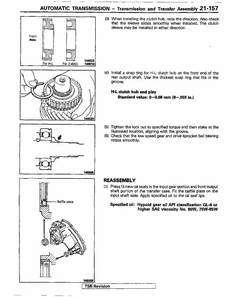
AUTOMATIC TRANSMISSION - Transmission and Transfer Assembly 21-157
Front A \ I
(3) When installing the clutch hub, note the direction. Also check that the sleeve slides smoothly when installed. The clutch sleeve may be installed in either direction.
(4) Install a snap ring for H-L clutch hub on the front end of the rear output shaft. Use the thickest snap ring that fits in the groove.
H-L clutch hub end play Standard value: O-0.08 mm (O-.003 in.)
(5) Tighten the lock nut to specified torque and then stake at the illustrated location, aligning with the groove.
(6) Check that the low speed gear and drive sprocket ball bearing rotate smoothly.
REASSEMBLY (1) Press fii new oil seals in the input gear portion and front output
shaft portion of the transfer case. Fit the baffle plate on the input shaft side. Apply specified oil to the oil seal lips.
Specified oil: Hypoid gear oil API classification GL-4 or higher SAE viscosity No. 8OW, 75W-85W

21-158 AUTOMATIC TRANSMISSION - Transmission and Transfer Assembly
(2) Press fit the ball bearing to the input gear, pushing the inner race. Check that the bearing rotates smoothly.
(3) Fit a snap ring on the front end of the input gear. Use the thickest one that fits in the groove.
Standard value : 0 - 0.06 mm (O-.002 in.)
(4) Insert the input gear assembly in the transfer case and fit a snap ring. Use the thickest one that fits in the groove.
Standard value : 0 - 0.00 mm (O-.002 in.1 (5) lnsert the needle bearing in the input gear.
(6) Install the H-L clutch sleeve and shift fork.
(7) Install the 24WD shift lug, distance piece and 24WD shift E rail in this order, and then tap the spring pin in place. s -~
I_
(8) Engage chain securely with the rear output shaft and front output shaft sprockets. Then, install the rear and front output shahs and chain together, while sliding the 2-4WD shift fork with the clutch sleeve attached over the 24WD shift rail.
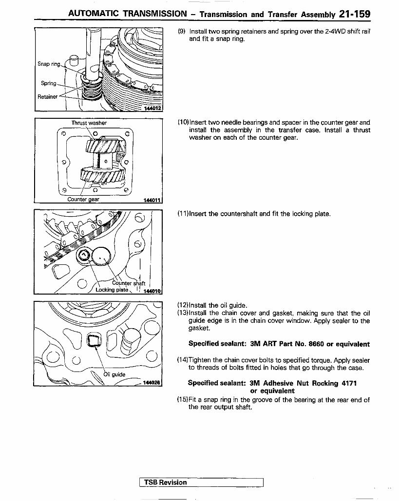
AUTOMATIC TRANSMISSION - Transmission and Transfer Assembly 21-I 59
Thrust washer
Counter gear
(9) Install two spring retainers and spring over the 2-4WO shift rail and fit a snap ring.
(IO) Insert two needle bearings and spacer in the counter gear and install the assembly in the transfer case. Install a thrust washer on each of the counter gear.
(1l)lnser-t the countershaft and fit the locking plate.
(12) Install the oil guide. (13)lnstall the chain cover and gasket, making sure that the oil
guide edge is in the chain cover window. Apply sealer to the gasket.
Specified sealant: 3M ART Part No. 8660 or equivalent
(14ITighten the chain cover bolts to specified torque. Apply sealer to threads of bolts fitted in holes that go through the case.
Specified sealant: 3M Adhesive Nut Rocking 4171 or equivalent
(15)Fit a snap ring in the groove of the bearing at the rear end of the rear output shaft.
1 TSB Revision
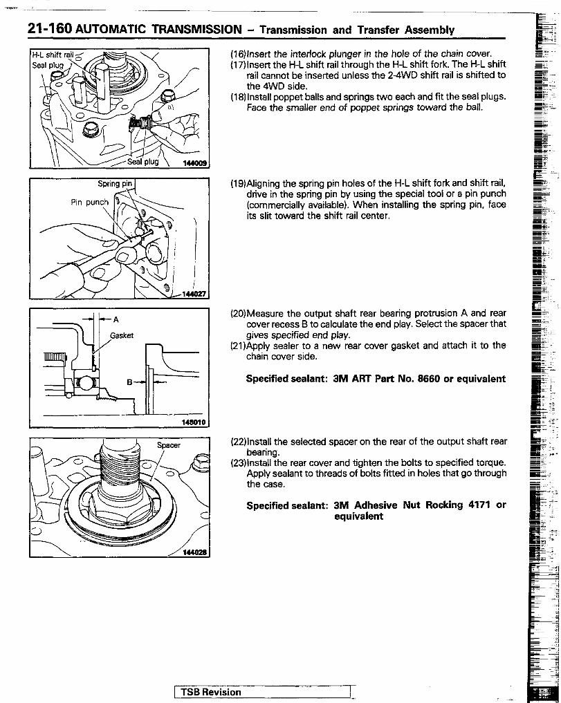
21-I 60 AUTOMATIC TRANSMISSION - Transmission and Transfer Assemblv
(16)lnsert the interlock plunger in the hole of the chain cover. (17)lnsert the H-L shift rail through the H-L shift fork. The H-L shift
rail cannot be inserted unless the 2-4WD shift rail is shifted to the 4WD side.
(18) Install poppet balls and springs two each and fit the seal plugs. Face the smaller end of poppet springs toward the ball.
(19)Aligning the spring pin holes of the H-L shift fork and shift rail, drive in the spring pin by using the special tool or a pin punch (commercially available). When installing the spring pin, face its slit toward the shift rail center.
(20)Measure the output shaft rear bearing protrusion A and rear cover recess B to calculate the end play. Select the spacer that gives specified end play.
(21)Apply sealer to a new rear cover gasket and attach it to the chain cover side.
Specified sealant: 3M ART Part No. 8660 or equivalent
(22):At/;he selected spacer on the rear of the output shaft rear
(23)lnstall the rear cover and tighten the bolts to specified torque. Apply sealant to threads of bolts fitted in holes that go through the case.
Specified sealant: 3M Adhesive Nut Rocking 4171 or equivalent
[ TSB Revision
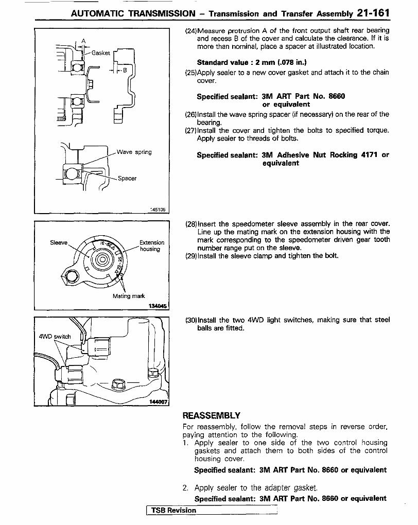
AUTOMATIC TRANSMISSION - Transmission and Transfer Assemblv 21-161
, A -II-B 3
=
Wave spring
-’ Spacer
i/
Extension housing
Mating mark 134MC -
4WD switch F I====
79 \
,
(24)Measure protrusion A of the front output shaft rear bearing and recess B of the cover and calculate the clearance. If it is more than nominal, place a spacer at illustrated location.
Standard value : 2 mm (.078 in.) (25)Apply sealer to a new cover gasket and attach it to the chain
cover.
Specified sealant: 3M ART Part No. 8660 or equivalent
(26)lnstall the wave spring spacer (if necessary) on the rear of the bearing.
(27)lnstall the cover and tighten the bolts to specified torque. Apply sealer to threads of bolts.
Specified sealant: 3M Adhesive Nut Rocking 4171 or equivalent
(2B)inser-t the speedometer sleeve assembly in the rear cover. Line up the mating mark on the extension housing with the mark corresponding to the speedometer driven gear tooth number range put on the sleeve.
(29)lnstall the sleeve clamp and tighten the bolt.
(30)lnstall the two 4WD light switches, making sure that steel balls are fitted.
REASSEMBLY For reassembly, follow the removal steps in reverse order, paying attention to the following. 1. Apply sealer to one side of the two control housing
gaskets and attach them to both sides of the control housing cover.
Specified sealant: 3M ART Part No. 8660 or equivalent
2. Apply sealer to the adapter gasket. Specified sealant: 3M ART Part No. 8660 or equivalent
1 TSB Revision 1
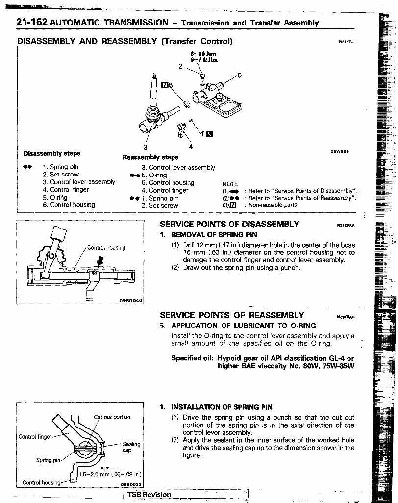
21-162 AUTOMATIC TRANSMISSION - Transmission and Transfer Assembly
,DlSASSEMBLY AND REASSEMBLY (Transfer Control)
Disassembly steps 3 4
Reassembly steps ** 1. Spring pin 3. Control lever assembly
2. Set screw ++ 5. O-ring 3. Control lever assembly 6. Control housing NOTE 4. Control finger 4. Control finger (l)++ : Refer to ‘Service Points of Disassembly” 5. o-ritig *+ 1. Spring pin (2)** : Refer to “Service Points of Reassembly”. 6. Control housing 2. Set screw (3)m : Non-reusable parts
SERVICE POINTS OF DISASSEMBLY N21KFu 1. REMOVAL OF SPRING PIN
(1) Drill 12 mm (.47 in.) diameter hole in the center of the boss 16 mm (63 in.) diameter on the control housing not to damage the control finger and control lever assembly.
(2) Draw out the spring pin using a punch.
SERVICE POINTS OF REASSEMBLY .-
N21WAB 5. APPLICATION OF LUBRICANT TO O-RING
Install the O-ring to the control lever assembly and apply a small amount of the specified oil on the O-ring.
Specified oil: Hypoid gear oil API classification GL-4 or higher SAE viscosity No. 8OW, 75W-85W
1. IbiSTALLATlON OF SPRING PIN Cut out portion (1) Drive the spring pin using a punch so that the cut out
portion of the spring pin is in the axial direction of the control lever assembly.
(2) Apply the sealant in the inner surface of the worked hole and drive the sealing cap up to the dimension shown in the figure.
TSBRevision -T =I

AUTOMATlC TRANSMISSION - Transmission and Transfer Assembly 21-I 63
TRANSMCSSION OIL COOLER REMOVAL AND INSTALLATION
I SO-35 Nm ?c--7-----. /3 Pre-removal Operation 0 Removal of Under
Post-installation Operation
I Removal steps
a+ 1. Eye bolts 2. Gaskets 3. Oil cooler assembly 4. Hose 5. Return tube 6. Feed tube
+a 7. Feed tube ++ 8. Return tube
NOTE 04w.5**
(1) Reverse the removal procedures to reinstall. 1;; ** : Refer to “Service Points of Removal”.
(4) tit j Refer to “Service Points of Installation”. Non-reusable parts
SERVICE POINTS OF REMOVAL N21ssAE 1. REMOVAL OF EYE BOLTS
Caution Loosen the eye bolts while tightening the weld nut of the oil cooler.
INSPECTION N2IScAo l Check the oil cooler fins for bend, damage and foreign
matters caught between fins. l Check the oil cooler tubes for crack, damage, clogging and
deterioration. l Check the gaskets for damage and deformation. l Check the eye bolts for clogging and deformation.
SERVICE POINTS OF INSTALLATION N2,SDbA 8. INSTALLATION OF RETURN TUBE/‘/. FEED TUBE
For installation of the feed tube and return tube to the transmission, first loosely tighten each coupling and clamp, and then make the final tightening in sequence from the feed tube and return tube coupling.
( TSB Revision
-