autocad lt 2010 - preview guide
TRANSCRIPT

8/3/2019 AutoCAD LT 2010 - Preview Guide
http://slidepdf.com/reader/full/autocad-lt-2010-preview-guide 1/33
AutoCAD LT ® 2010
Preview Guide
www.autodesk.com/autocadlt

8/3/2019 AutoCAD LT 2010 - Preview Guide
http://slidepdf.com/reader/full/autocad-lt-2010-preview-guide 2/33
AUTOCAD LT 2010 PREVIEW GUIDE
Table of ContentsIntroduction ......................................................................................................................... 3 User Interface ...................................................................................................................... 3
Initial Setup ...................................................................................................................... 3 Workspaces ..................................................................................................................... 4 Application Menu .............................................................................................................. 4 Ribbon .............................................................................................................................. 6 Quick Access Toolbar ...................................................................................................... 9 New Features Workshop ................................................................................................ 10
Document .......................................................................................................................... 10 Parametric Drawing ........................................................................................................ 10 Dynamic Blocks .............................................................................................................. 11 Annotation Tools ............................................................................................................ 15 Color Selection ............................................................................................................... 18 Measure Tools ............................................................................................................... 19 Reverse Tools ................................................................................................................ 20 Spline Editing Tools ....................................................................................................... 21 Align Objects .................................................................................................................. 22 Purge Tools .................................................................................................................... 23 Viewport Rotation Tools ................................................................................................. 23 External References ....................................................................................................... 24 Quick Views ................................................................................................................... 27
Collaborate ........................................................................................................................ 27 PDF Support .................................................................................................................. 27 Drawing File Format ....................................................................................................... 30 eTransmit ....................................................................................................................... 31 Autodesk Seek ............................................................................................................... 31
Optimize ............................................................................................................................. 32 CUIx File ........................................................................................................................ 32 Online License Transfer ................................................................................................. 33
Summary............................................................................................................................ 33
www.autodesk.com/autocadlt 2 Confidential—Subject to Non-Disclosure Agreement

8/3/2019 AutoCAD LT 2010 - Preview Guide
http://slidepdf.com/reader/full/autocad-lt-2010-preview-guide 3/33
AUTOCAD LT 2010 PREVIEW GUIDE
IntroductionAutoCAD LT ® software is known for its efficiency, power, and reliability. And now it‘s betterthan ever. With AutoCAD LT 2010, we’ve added more 2D features you’ve been asking forlike ALIGN, xref tools, and block attribute commands. High-quality PDF output means youcan easily share drawings with almost anyone. And you can save time by attaching PDFsas an underlay in drawing files. The professional standard in drafting and detailing softwarenow has even more ways to increase your productivity. Take full command with AutoCADLT 2010.
User Interface
Initial SetupEasily tailor the AutoCAD LT environment to meet your needs using Initial Setup, which isdisplayed the first time you launch AutoCAD LT. With Initial Setup you can choose your
industry as well as workspace and drawing template preferences. The choices you make inthe Initial Setup affect the default settings of various AutoCAD LT functionality, includingdrawing templates, Autodesk ® Seek filters, the Unified Online Experience portal, andworkspaces.
Figure 1. Initial Setup
You can also access the Initial Setup dialog from the User Preferences tab of the Optionsdialog box.
www.autodesk.com/autocadlt 3 Confidential—Subject to Non-Disclosure Agreement

8/3/2019 AutoCAD LT 2010 - Preview Guide
http://slidepdf.com/reader/full/autocad-lt-2010-preview-guide 4/33
AUTOCAD LT 2010 PREVIEW GUIDE
Figure 2. Initial Setup on User Preferences tab of the Options dialog box
Workspaces
When you specify Initial Setup options, AutoCAD LT automatically creates a newworkspace based on your choices and sets it current. The name of the current workspaceis displayed in the status bar next to the Workspace Switching icon, and you can select it toaccess the Workspace menu.
Figure 3. Workspace menu
Application MenuThe Application menu, in the upper left corner of the AutoCAD LT display, has beenstreamlined to provide you with easy access to common tools. You can create, open, save,print, and publish AutoCAD LT files, send the current drawing as an email attachment, and
www.autodesk.com/autocadlt 4 Confidential—Subject to Non-Disclosure Agreement

8/3/2019 AutoCAD LT 2010 - Preview Guide
http://slidepdf.com/reader/full/autocad-lt-2010-preview-guide 5/33
AUTOCAD LT 2010 PREVIEW GUIDE
produce electronic transmittal sets. In addition, you can perform drawing maintenance,such as audit and purge, and close drawings.
A search tool at the top of the Application menu enables you to query the Quick Accesstoolbar, the Application menu, and the currently loaded ribbon to locate commands, ribbonpanel names, and other ribbon controls.
Buttons at the top of the Application menu provide easy access to Recent or Opendocuments, and a new option in the Recent Documents list enables you to sort by accessdate in addition to size, type, or as an ordered list.
Figure 4. Application menu
www.autodesk.com/autocadlt 5 Confidential—Subject to Non-Disclosure Agreement

8/3/2019 AutoCAD LT 2010 - Preview Guide
http://slidepdf.com/reader/full/autocad-lt-2010-preview-guide 6/33
AUTOCAD LT 2010 PREVIEW GUIDE
RibbonThe ribbon has been updated to provide greater flexibility, easier access to tools, andconsistency across Autodesk applications.
You can drag a panel off the ribbon to display it as a sticky panel. Sticky panels remaindisplayed, even when selecting a different tab, until you select the option to Return Panelsto Ribbon.
Figure 5. Ribbon and sticky panels The vertical ribbon, which can be displayed by undocking the ribbon from the top of thedisplay, has been updated to show the tab names along the side. The panel titles areturned off by default, but can be restored through a right-click menu. Certain panels haveadditional tools located on a slide-out section. When resizing the vertical ribbon, buttonsautomatically flow to the next or previous row and other elements, such as slider bars,dynamically shorten or lengthen.
www.autodesk.com/autocadlt 6 Confidential—Subject to Non-Disclosure Agreement

8/3/2019 AutoCAD LT 2010 - Preview Guide
http://slidepdf.com/reader/full/autocad-lt-2010-preview-guide 7/33
AUTOCAD LT 2010 PREVIEW GUIDE
Figure 6. Vertical ribbon with slide-out panel
If you customized the Dashboard in AutoCAD LT 2008, you can easily convert your custom
dashboard panels to new ribbon panels using the Transfer tab in the Customize UserInterface (CUI) Editor. The newly converted panels are then displayed under the RibbonPanels node in the same CUIx file as the dashboard panels. Once converted, you can addthe new panels to a tab or transfer them to another CUIx file.
www.autodesk.com/autocadlt 7 Confidential—Subject to Non-Disclosure Agreement

8/3/2019 AutoCAD LT 2010 - Preview Guide
http://slidepdf.com/reader/full/autocad-lt-2010-preview-guide 8/33
AUTOCAD LT 2010 PREVIEW GUIDE
Figure 7. Dashboard conversion
Enhanced ribbon functionality in AutoCAD LT 2010 enables you to customize contextualribbon tab states, which control the display of ribbon tabs and panels based on either thetype of object selected in the drawing window or the active command. You can display aribbon tab that is assigned to a ribbon contextual tab state either on its own tab or with itspanels merged onto each of the ribbon tabs in the current workspace.
To add a ribbon tab to a ribbon contextual state, drag a ribbon tab from the Tabs node inthe “Customizations In…” pane to an object under the Contextual Tab States node. Forexample, if you want the Home tab to become active whenever you select a Polylineobject, drag the Home-2D ribbon tab to the Polyline object under the Ribbon Contextual
Tab States. You can then select it and modify its display type to indicate if it should bedisplayed as its own tab or merged onto each ribbon tab.
Figure 8. Ribbon Contextual Tab States
www.autodesk.com/autocadlt 8 Confidential—Subject to Non-Disclosure Agreement

8/3/2019 AutoCAD LT 2010 - Preview Guide
http://slidepdf.com/reader/full/autocad-lt-2010-preview-guide 9/33
AUTOCAD LT 2010 PREVIEW GUIDE
Quick Access ToolbarThe Quick Access toolbar has been enhanced with more functionality and to ensureconsistency with other Windows ® applications. The Undo and Redo tools include historysupport and the right-click menu includes new options that enable you to easily removetools from the toolbar, add separators between tools, and display the Quick Access toolbarabove or below the ribbon.
Figure 9. Quick Access toolbar right-click menu
In addition to the right-click menu, the Quick Access toolbar includes a new flyout menu,which displays a list of common tools that you can select to include in the Quick Accesstoolbar. The “More Commands…” option in the flyout menu provides easy access toadditional tools using the Command List pane in the CUI Editor. Other options enable youto show the menu bar or display the Quick Access toolbar below the ribbon.
Figure 10. Quick Access toolbar flyout menu
You can further customize the Quick Access toolbar using the new Quick Access toolbarnode in the CUI Editor. Use this node to create multiple versions of the Quick Accesstoolbar and add them to the appropriate workspaces.
www.autodesk.com/autocadlt 9 Confidential—Subject to Non-Disclosure Agreement

8/3/2019 AutoCAD LT 2010 - Preview Guide
http://slidepdf.com/reader/full/autocad-lt-2010-preview-guide 10/33
AUTOCAD LT 2010 PREVIEW GUIDE
Figure 11. Quick Access toolbar customization
New Features WorkshopThe New Features Workshop has been updated to include AutoCAD LT 2010 functionality.This interactive learning tool helps you discover the newest functionality with minimal effort.You can access the New Features Workshop from the drop-down on the InfoCentertoolbar, to the right of the Help button.
Figure 12. Access to the New Features Workshop
DocumentIn AutoCAD LT 2010, your wishes are our new commands. Many features in this release
were inspired directly by user suggestions and feedback. With these new and improvedtools, AutoCAD LT helps make drafting easier and more productive.
Parametric DrawingAutoCAD ® 2010 software now includes the ability to create and modify geometric anddimensional constraints, which help ensure that specific relationships and measurementsremain persistent even as objects are modified. AutoCAD LT 2010 cannot createparametric constraints, but it can view, use, or delete them if they have already beencreated in AutoCAD 2010. The tools for displaying and managing the geometric and
www.autodesk.com/autocadlt 10 Confidential—Subject to Non-Disclosure Agreement
8/3/2019 AutoCAD LT 2010 - Preview Guide
http://slidepdf.com/reader/full/autocad-lt-2010-preview-guide 11/33
AUTOCAD LT 2010 PREVIEW GUIDE
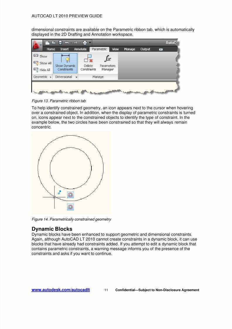
dimensional constraints are available on the Parametric ribbon tab, which is automaticallydisplayed in the 2D Drafting and Annotation workspace.
Figure 13. Parametric ribbon tab
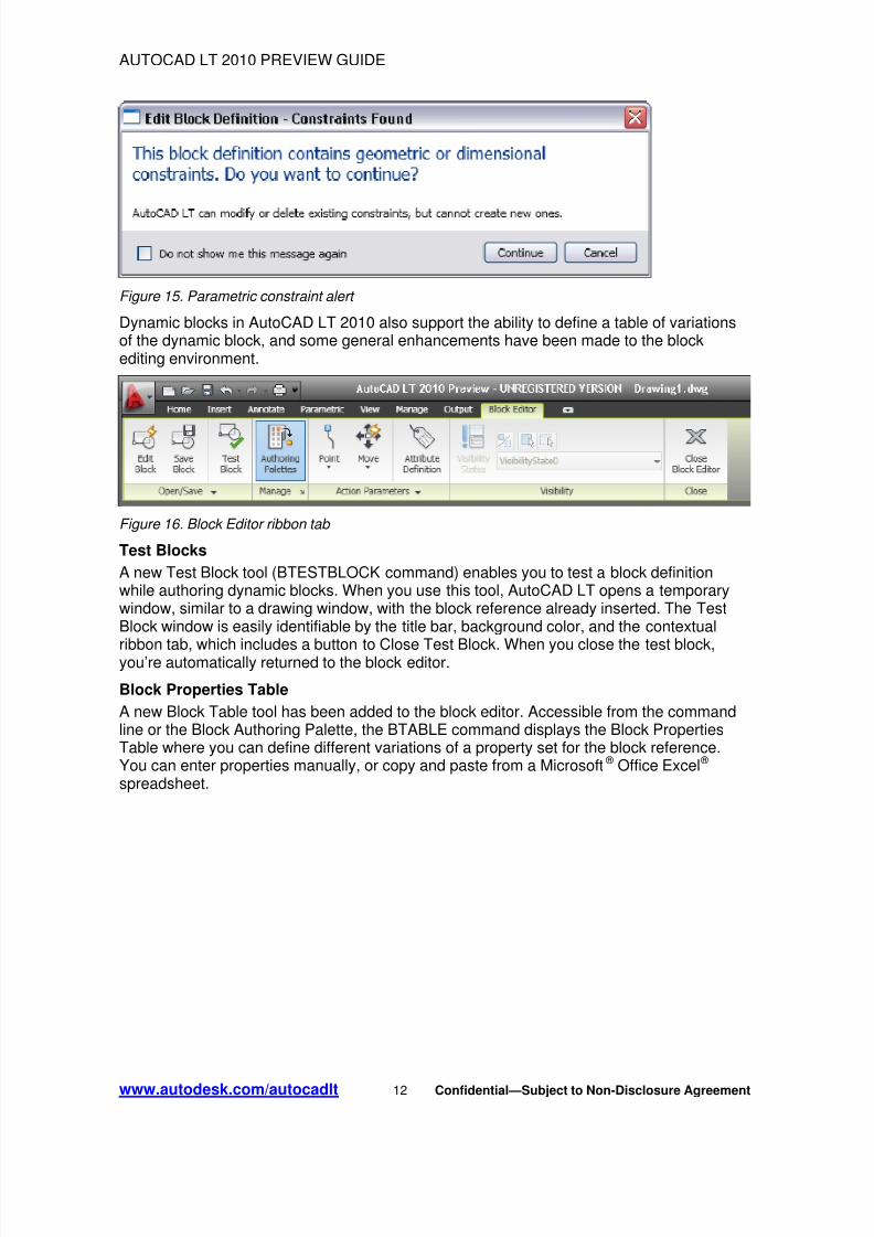
To help identify constrained geometry, an icon appears next to the cursor when hoveringover a constrained object. In addition, when the display of parametric constraints is turnedon, icons appear next to the constrained objects to identify the type of constraint. In theexample below, the two circles have been constrained so that they will always remainconcentric.
Figure 14. Parametrically constrained geometry
Dynamic BlocksDynamic blocks have been enhanced to support geometric and dimensional constraints.Again, although AutoCAD LT 2010 cannot create constraints in a dynamic block, it can useblocks that have already had constraints added. If you attempt to edit a dynamic block thatcontains parametric constraints, a warning message informs you of the presence of theconstraints and asks if you want to continue.
www.autodesk.com/autocadlt 11 Confidential—Subject to Non-Disclosure Agreement
8/3/2019 AutoCAD LT 2010 - Preview Guide
http://slidepdf.com/reader/full/autocad-lt-2010-preview-guide 12/33
AUTOCAD LT 2010 PREVIEW GUIDE
Figure 15. Parametric constraint alert
Dynamic blocks in AutoCAD LT 2010 also support the ability to define a table of variationsof the dynamic block, and some general enhancements have been made to the blockediting environment.
Figure 16. Block Editor ribbon tab
Test Blocks
A new Test Block tool (BTESTBLOCK command) enables you to test a block definitionwhile authoring dynamic blocks. When you use this tool, AutoCAD LT opens a temporarywindow, similar to a drawing window, with the block reference already inserted. The TestBlock window is easily identifiable by the title bar, background color, and the contextual
ribbon tab, which includes a button to Close Test Block. When you close the test block,you’re automatically returned to the block editor.
Block Properties Table
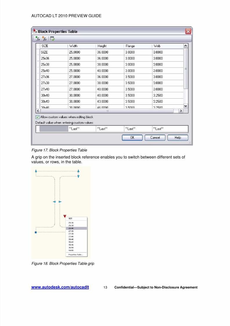
A new Block Table tool has been added to the block editor. Accessible from the commandline or the Block Authoring Palette, the BTABLE command displays the Block PropertiesTable where you can define different variations of a property set for the block reference.You can enter properties manually, or copy and paste from a Microsoft ® Office Excel ® spreadsheet.
www.autodesk.com/autocadlt 12 Confidential—Subject to Non-Disclosure Agreement
8/3/2019 AutoCAD LT 2010 - Preview Guide
http://slidepdf.com/reader/full/autocad-lt-2010-preview-guide 13/33
AUTOCAD LT 2010 PREVIEW GUIDE
Figure 17. Block Properties Table
A grip on the inserted block reference enables you to switch between different sets ofvalues, or rows, in the table.
Figure 18. Block Properties Table grip
www.autodesk.com/autocadlt 13 Confidential—Subject to Non-Disclosure Agreement

8/3/2019 AutoCAD LT 2010 - Preview Guide
http://slidepdf.com/reader/full/autocad-lt-2010-preview-guide 14/33
AUTOCAD LT 2010 PREVIEW GUIDE
Action Bars
The display and positioning of Action objects in the block editor is enhanced to beconsistent with Constraint bars. Action objects are no longer placed individually in the blockeditor; rather they are automatically grouped into Action bars based on the parameters withwhich they are associated. You can toggle between the new and old display styles bysetting the BACTIONBARMODE system variable prior to entering the Block Editor.
Figure 19. Action Bars
When viewing the block definition with Action bars turned on, you can quickly tell whichactions are associated with which parameters and how many actions each of theparameters affects. You can also see which parameter has its “Chain actions” propertyenabled. If you roll over an action in an Action bar, both the associated parameter and
affected geometry are highlighted.
Block Editor Settings
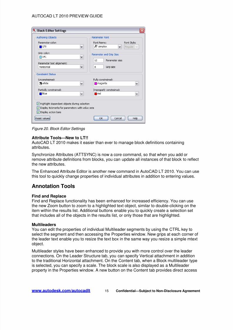
A new dialog box, launched with the command BESETTINGS, enables you to control allthe settings for the Block Editor environment in one place. You can apply colors to objectsbased on their constraint status, making it easy to identify objects that are partially, fully, orover-constrained, or that have no constraints at all. The system variableBCONSTATUSMODE controls whether this shading is used.
www.autodesk.com/autocadlt 14 Confidential—Subject to Non-Disclosure Agreement
8/3/2019 AutoCAD LT 2010 - Preview Guide
http://slidepdf.com/reader/full/autocad-lt-2010-preview-guide 15/33
AUTOCAD LT 2010 PREVIEW GUIDE
Figure 20. Block Editor Settings
Attribute Tools—New to LT!!AutoCAD LT 2010 makes it easier than ever to manage block definitions containingattributes.
Synchronize Attributes (ATTSYNC) is now a core command, so that when you add orremove attribute definitions from blocks, you can update all instances of that block to reflectthe new attributes.
The Enhanced Attribute Editor is another new command in AutoCAD LT 2010. You can usethis tool to quickly change properties of individual attributes in addition to entering values.
Annotation Tools
Find and ReplaceFind and Replace functionality has been enhanced for increased efficiency. You can usethe new Zoom button to zoom to a highlighted text object, similar to double-clicking on theitem within the results list. Additional buttons enable you to quickly create a selection setthat includes all of the objects in the results list, or only those that are highlighted.
Multileaders
You can edit the properties of individual Multileader segments by using the CTRL key toselect the segment and then accessing the Properties window. New grips at each corner ofthe leader text enable you to resize the text box in the same way you resize a simple mtextobject.
Multileader styles have been enhanced to provide you with more control over the leaderconnections. On the Leader Structure tab, you can specify Vertical attachment in additionto the traditional Horizontal attachment. On the Content tab, when a Block multileader typeis selected, you can specify a scale. The block scale is also displayed as a Multileaderproperty in the Properties window. A new button on the Content tab provides direct access
www.autodesk.com/autocadlt 15 Confidential—Subject to Non-Disclosure Agreement

8/3/2019 AutoCAD LT 2010 - Preview Guide
http://slidepdf.com/reader/full/autocad-lt-2010-preview-guide 16/33
AUTOCAD LT 2010 PREVIEW GUIDE
to the Text Style dialog box, enabling you to create and modify text styles without exitingthe Multileader Style dialog box.
The MLEADEREDIT command has been streamlined by eliminating the need for you toselect an option to add or remove leader lines. Instead, it adds leaders by default until youselect the option to remove leaders.
Multiline TextMtext improvements include a default column mode of Dynamic with manual height. Inaddition, the corner grips on mtext objects are now consistent with the corner grips on tableobjects.
Spell CheckThe Check Spelling dialog box has been updated to include an Undo button, which enablesyou to undo actions you made for the previous spelling mistake. In addition, the SelectObjects button has been enhanced so that you can begin selecting objects to check withoutfirst having to choose the Select Objects option from the drop-down list.
DimensionsEnhancements to dimension styles and properties provide more control over the displayand placement of dimension text.
The Text tab of the Dimension Style dialog box has been updated with a new textplacement option that enables you to position dimension text below the dimension line. Youcan also control the direction of the text using the new View Direction option, in which youcan specify that the text be displayed from Left-to-Right or Right-to-Left. The Propertiespalette has been updated to include these new properties as well.
The Primary and Alternate Units tabs of the Dimension Style dialog box include new sub-unit controls in the suppression of leading zeros. Instead of displaying a dimension valueless than 1 as a decimal, you can specify a sub-units factor and suffix. For example, if theunit is 1 meter, you could specify a sub-unit factor of 100 and sub-unit suffix of cm. In thiscase, when the dimension value is less than 1, such as .96, it would display as 96cminstead of .96m. The new sub-units properties are also included in the Properties palette.
www.autodesk.com/autocadlt 16 Confidential—Subject to Non-Disclosure Agreement

8/3/2019 AutoCAD LT 2010 - Preview Guide
http://slidepdf.com/reader/full/autocad-lt-2010-preview-guide 17/33
AUTOCAD LT 2010 PREVIEW GUIDE
Figure 21. Sub-unit controls
HatchWhen a hatch boundary area is not found, AutoCAD LT attempts to show you where theproblem may have occurred. Red circles appear around endpoints near where any gap ingeometry is estimated to be.
Figure 22. Hatch boundary gap
www.autodesk.com/autocadlt 17 Confidential—Subject to Non-Disclosure Agreement

8/3/2019 AutoCAD LT 2010 - Preview Guide
http://slidepdf.com/reader/full/autocad-lt-2010-preview-guide 18/33
AUTOCAD LT 2010 PREVIEW GUIDE
Additional enhancements provide more robust boundary detection and the ability to editnon-associative hatch objects. You can select on a non-associative hatch and then useintuitive grips to dynamically change its shape.
Figure 23. Non-associative hatch editing
Color SelectionIn AutoCAD LT 2010, you can set layer colors and pick from the AutoCAD LT Color Indexwith ease. Access the Select Color dialog box directly from the Layer drop-down list byclicking on the layer color swatch. If the layer has a viewport color override, the colorswatch has a white border. The new color you select applies to the appropriate viewportcolor override or global color. Behavior within the Select Color dialog box has also beenimproved. As you hover the cursor over a color swatch, the arrow cursor and a blackborder are displayed, in addition to the traditional white border, making it easier to see
which swatch you are about to select.
Figure 24. Color selection
www.autodesk.com/autocadlt 18 Confidential—Subject to Non-Disclosure Agreement
8/3/2019 AutoCAD LT 2010 - Preview Guide
http://slidepdf.com/reader/full/autocad-lt-2010-preview-guide 19/33
AUTOCAD LT 2010 PREVIEW GUIDE
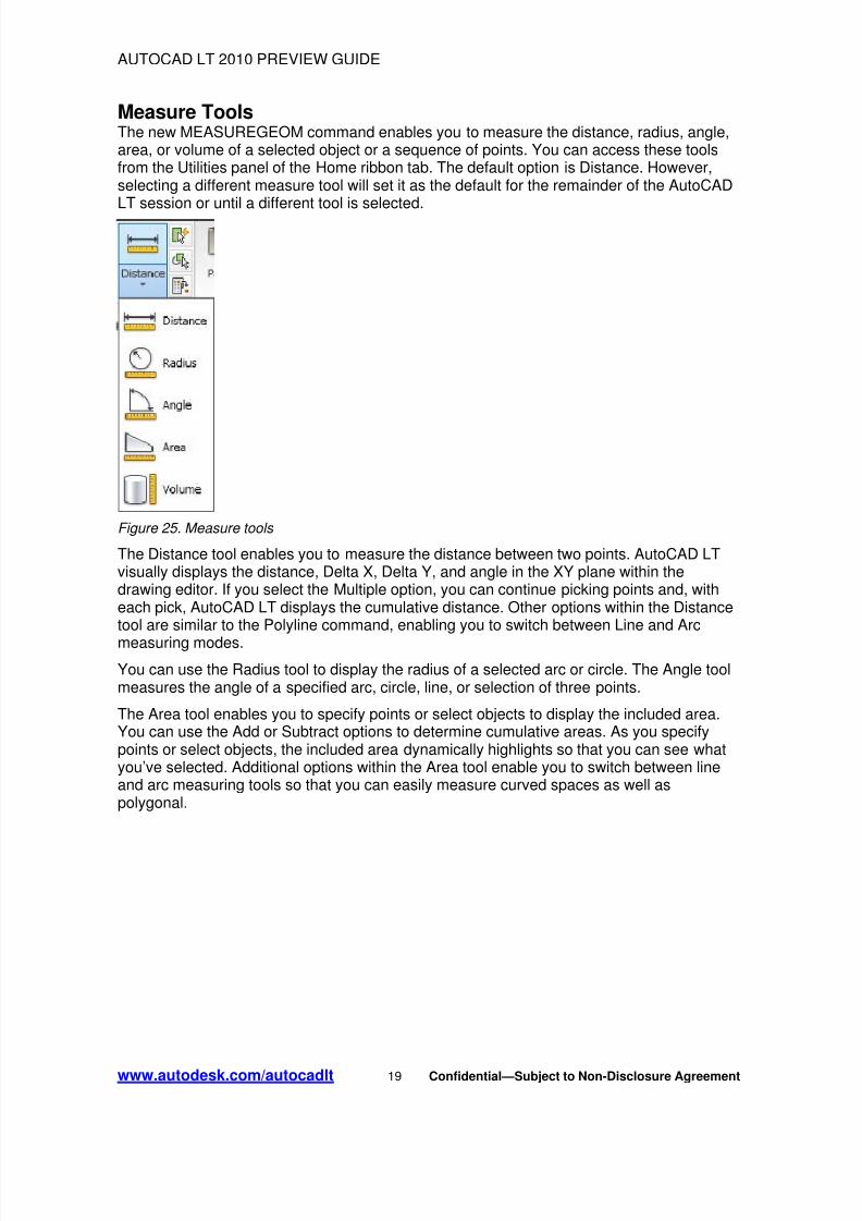
Measure ToolsThe new MEASUREGEOM command enables you to measure the distance, radius, angle,area, or volume of a selected object or a sequence of points. You can access these toolsfrom the Utilities panel of the Home ribbon tab. The default option is Distance. However,selecting a different measure tool will set it as the default for the remainder of the AutoCADLT session or until a different tool is selected.
Figure 25. Measure tools The Distance tool enables you to measure the distance between two points. AutoCAD LTvisually displays the distance, Delta X, Delta Y, and angle in the XY plane within thedrawing editor. If you select the Multiple option, you can continue picking points and, witheach pick, AutoCAD LT displays the cumulative distance. Other options within the Distancetool are similar to the Polyline command, enabling you to switch between Line and Arc
measuring modes.
You can use the Radius tool to display the radius of a selected arc or circle. The Angle toolmeasures the angle of a specified arc, circle, line, or selection of three points.
The Area tool enables you to specify points or select objects to display the included area.You can use the Add or Subtract options to determine cumulative areas. As you specifypoints or select objects, the included area dynamically highlights so that you can see whatyou’ve selected. Additional options within the Area tool enable you to switch between lineand arc measuring tools so that you can easily measure curved spaces as well aspolygonal.
www.autodesk.com/autocadlt 19 Confidential—Subject to Non-Disclosure Agreement

8/3/2019 AutoCAD LT 2010 - Preview Guide
http://slidepdf.com/reader/full/autocad-lt-2010-preview-guide 20/33
AUTOCAD LT 2010 PREVIEW GUIDE
Figure 26. Area highlighting You can use the Volume tool to specify boundary points with visual feedback similar to theArea option, and then specify a height to determine the volume. Additionally, you candisplay the volume of selected solids or regions.
Figure 27. Volume highlighting Reverse ToolsThe new REVERSE command enables you to reverse the direction of lines, polylines,splines, and helixes. Simply select the object(s) to reverse. The ability to change thedirection of these objects provides you with more control, such as the display of speciallinetypes.
www.autodesk.com/autocadlt 20 Confidential—Subject to Non-Disclosure Agreement
8/3/2019 AutoCAD LT 2010 - Preview Guide
http://slidepdf.com/reader/full/autocad-lt-2010-preview-guide 21/33
AUTOCAD LT 2010 PREVIEW GUIDE
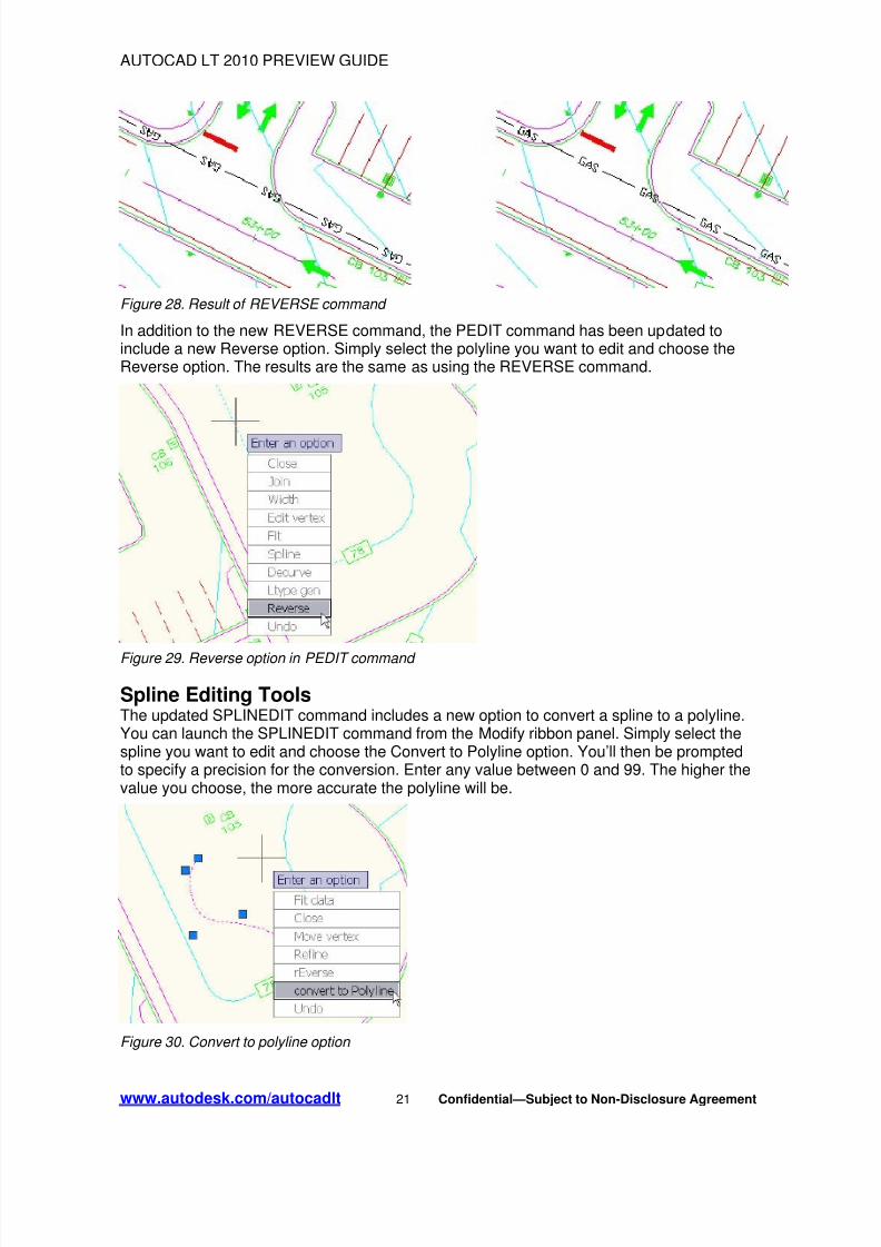
Figure 28. Result of REVERSE command
In addition to the new REVERSE command, the PEDIT command has been updated toinclude a new Reverse option. Simply select the polyline you want to edit and choose theReverse option. The results are the same as using the REVERSE command.
Figure 29. Reverse option in PEDIT command
Spline Editing ToolsThe updated SPLINEDIT command includes a new option to convert a spline to a polyline.You can launch the SPLINEDIT command from the Modify ribbon panel. Simply select thespline you want to edit and choose the Convert to Polyline option. You’ll then be promptedto specify a precision for the conversion. Enter any value between 0 and 99. The higher thevalue you choose, the more accurate the polyline will be.
Figure 30. Convert to polyline option
www.autodesk.com/autocadlt 21 Confidential—Subject to Non-Disclosure Agreement
8/3/2019 AutoCAD LT 2010 - Preview Guide
http://slidepdf.com/reader/full/autocad-lt-2010-preview-guide 22/33
AUTOCAD LT 2010 PREVIEW GUIDE
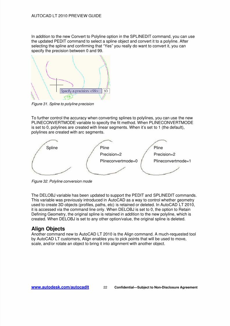
In addition to the new Convert to Polyline option in the SPLINEDIT command, you can usethe updated PEDIT command to select a spline object and convert it to a polyline. Afterselecting the spline and confirming that “Yes” you really do want to convert it, you canspecify the precision between 0 and 99.
Figure 31. Spline to polyline precision
To further control the accuracy when converting splines to polylines, you can use the newPLINECONVERTMODE variable to specify the fit method. When PLINECONVERTMODEis set to 0, polylines are created with linear segments. When it’s set to 1 (the default),polylines are created with arc segments.
Spline Pline Pline
Precision=2 Precision=2
Plineconvertmode=0 Plineconvertmode=1
Figure 32. Polyline conversion mode The DELOBJ variable has been updated to support the PEDIT and SPLINEDIT commands.This variable was previously introduced in AutoCAD as a way to control whether geometryused to create 3D objects (profiles, paths, etc) is retained or deleted. In AutoCAD LT 2010,it is accessed via the command line only. When DELOBJ is set to 0, the option to RetainDefining Geometry, the original spline is retained in addition to the new polyline, which iscreated. When DELOBJ is set to any other option/value, the original spline is deleted.
Align ObjectsAnother command new to AutoCAD LT 2010 is the Align command. A much-requested toolby AutoCAD LT customers, Align enables you to pick points that will be used to move,scale, and/or rotate an object to bring it into alignment with another object.
www.autodesk.com/autocadlt 22 Confidential—Subject to Non-Disclosure Agreement
8/3/2019 AutoCAD LT 2010 - Preview Guide
http://slidepdf.com/reader/full/autocad-lt-2010-preview-guide 23/33
AUTOCAD LT 2010 PREVIEW GUIDE
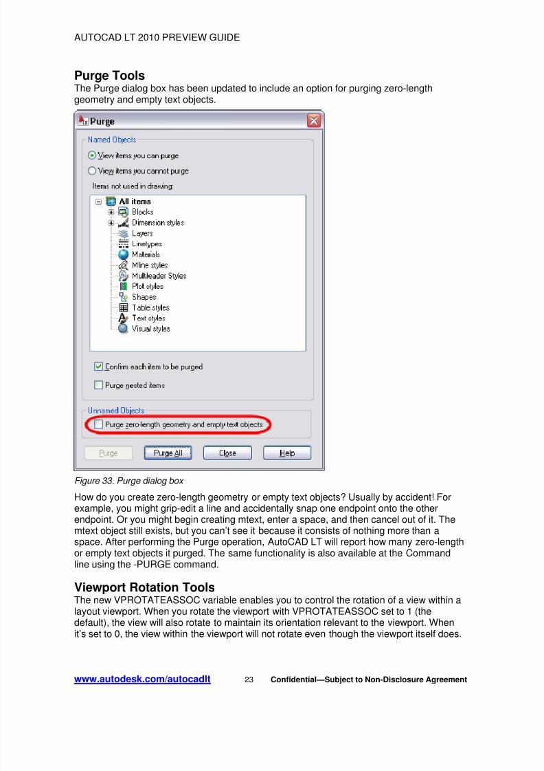
Purge ToolsThe Purge dialog box has been updated to include an option for purging zero-lengthgeometry and empty text objects.
Figure 33. Purge dialog box How do you create zero-length geometry or empty text objects? Usually by accident! Forexample, you might grip-edit a line and accidentally snap one endpoint onto the otherendpoint. Or you might begin creating mtext, enter a space, and then cancel out of it. Themtext object still exists, but you can’t see it because it consists of nothing more than a
space. After performing the Purge operation, AutoCAD LT will report how many zero-lengthor empty text objects it purged. The same functionality is also available at the Commandline using the -PURGE command.
Viewport Rotation ToolsThe new VPROTATEASSOC variable enables you to control the rotation of a view within alayout viewport. When you rotate the viewport with VPROTATEASSOC set to 1 (thedefault), the view will also rotate to maintain its orientation relevant to the viewport. Whenit’s set to 0, the view within the viewport will not rotate even though the viewport itself does.
www.autodesk.com/autocadlt 23 Confidential—Subject to Non-Disclosure Agreement

8/3/2019 AutoCAD LT 2010 - Preview Guide
http://slidepdf.com/reader/full/autocad-lt-2010-preview-guide 24/33
AUTOCAD LT 2010 PREVIEW GUIDE
Original Viewport VPROTATEASSOC=0 VPROTATEASSOC=1
Figure 34. Viewport rotation
External ReferencesAutoCAD LT 2010 provides a consolidated interface and increased flexibility for working
with externally referenced files in a variety of formats, including DWGTM
, DWFTM
, DGN,PDF, and image files.
Geographic DataYou can attach externally referenced drawing files using geographic data. If both the hostdrawing and the external reference drawing have a geographic location, a new option onthe External References dialog box enables you to locate the attached xref relative to thehost drawing using Geographic Data. A similar option is available in the Insert dialog box.
Reference ToolsThe Reference panel on the Insert tab of the ribbon provides tools for you to attach andmodify externally referenced files. Use the Attach tool to select a DWG, DWF, DGN, PDF,
or image file and specify attachment options. Additional tools enable you to clip a selectedreference, adjust its Fade, Contrast, and Brightness settings, control its layer visibility,display reference frames, snap to underlay geometry, and adjust xref fading.
Figure 35. Reference ribbon panel
When you select a reference file in the drawing, a relevant contextual tab is automaticallydisplayed in the Ribbon. For example, if you select a PDF underlay, the PDF Underlay tabis displayed providing you easy access to PDF underlay tools.
www.autodesk.com/autocadlt 24 Confidential—Subject to Non-Disclosure Agreement

8/3/2019 AutoCAD LT 2010 - Preview Guide
http://slidepdf.com/reader/full/autocad-lt-2010-preview-guide 25/33
AUTOCAD LT 2010 PREVIEW GUIDE
Figure 36. PDF Underlay contextual tab
Easily edit the clip boundary of any reference using grips. You can even invert the clip witha simple click on the invert grip.
Figure 37. Inverted clip boundary
You can display the reference frame for each type of reference using specific frame systemvariables such as DWFFRAME, DGNFRAME, and PDFFRAME. To quickly override theseindividual system variables, use the Frame tool (FRAME system variable) in the
References panel of the Insert ribbon tab. You can hide frames, display and plot them, ordisplay but not plot them.
Figure 38. Frame controls
You can enable object snapping for geometry in underlay files. To control this behavior forspecific reference types, use their individual system variables such as DWFOSNAP,
www.autodesk.com/autocadlt 25 Confidential—Subject to Non-Disclosure Agreement

8/3/2019 AutoCAD LT 2010 - Preview Guide
http://slidepdf.com/reader/full/autocad-lt-2010-preview-guide 26/33
AUTOCAD LT 2010 PREVIEW GUIDE
DGNOSNAP, and PDFOSNAP. You can override these individual system variables usingthe Snap to Underlays tool (UOSNAP system variable) in the References panel of theInsert ribbon tab.
Figure 39. Underlay controls
When you open a drawing that has unresolved references, a new tool helps identify themissing files.
Figure 40. Unresolved reference files
If you choose Update, AutoCAD LT opens the External References palette so you can re-path the missing files. If you choose Ignore, the warning closes and takes no action. If youalways want to ignore unresolved references, use the checkbox at the bottom to stop thewarning from displaying again.
This is a great improvement over previous versions, when you had to manually search for
missing references by checking the command line when opening a file, scouring thedrawing for the text strings identifying unresolved references, or looking in the ExternalReferences palette.
More External Reference Commands—New to LT!!Several external reference commands previously only available in AutoCAD ® softwarehave now been included in AutoCAD LT 2010.
The first is In-Place Reference Editing (REFEDIT). This feature enables you to makechanges directly to a referenced file without opening it. REFEDIT can also be used on
www.autodesk.com/autocadlt 26 Confidential—Subject to Non-Disclosure Agreement
8/3/2019 AutoCAD LT 2010 - Preview Guide
http://slidepdf.com/reader/full/autocad-lt-2010-preview-guide 27/33
AUTOCAD LT 2010 PREVIEW GUIDE
block references, if you have a situation where you want to be able to modify a block andstill see its surrounding geometry.
Related to REFEDIT is XOPEN, which enables you to right-click on an xref and open itdirectly from the drawing editor or the External References palette. Now you can quicklyopen a referenced file without having to list it, remember its name, and browse your
computer or server to find it.Finally, the ability to clip an external reference is now fully functional in AutoCAD LT 2010.Now you can use XCLIP to create your own clipping boundaries, turn them on or off, andeven invert them, as mentioned above.
Quick ViewsThe preview images for Quick View Layouts and Quick View Drawings have beenenhanced to include a preview image of Model space in addition to the layout previews.
CollaborateWith AutoCAD LT, collaboration is a seamless operation. Share critical design datasecurely, efficiently, and accurately with AutoCAD LT. Experience the benefits of nativeDWG support, one of the world’s most widely used design data formats, allowing you tokeep everyone in the loop at all times. When you need a non-editable file instead, quicklyand easily create DWF or PDF files for world-wide readability. It’s collaboration at its best.
PDF Support
PDF OutputPDF output now provides more flexibility and higher quality than was previously available.The default vector resolution has been increased from 400 to 600 dpi to produce preciselineweights at a reasonable file size. To further improve the visual quality of PDF output,
TrueType fonts are exported as text rather than as graphics. This improves the visualquality of text and also enables highlighting, searching, and copying text within the PDFviewer. Additional improvements include the ability to specify merge control, include layerinformation, and automatically preview the plotted PDF.
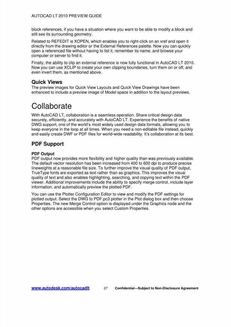
You can use the Plotter Configuration Editor to view and modify the PDF settings forplotted output. Select the DWG to PDF.pc3 plotter in the Plot dialog box and then chooseProperties. The new Merge Control option is displayed under the Graphics node and theother options are accessible when you select Custom Properties.
www.autodesk.com/autocadlt 27 Confidential—Subject to Non-Disclosure Agreement
8/3/2019 AutoCAD LT 2010 - Preview Guide
http://slidepdf.com/reader/full/autocad-lt-2010-preview-guide 28/33
AUTOCAD LT 2010 PREVIEW GUIDE
Figure 41. DWG to PDF Plotter Configuration properties
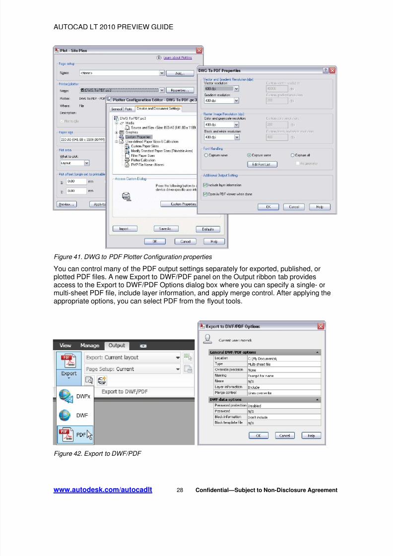
You can control many of the PDF output settings separately for exported, published, orplotted PDF files. A new Export to DWF/PDF panel on the Output ribbon tab providesaccess to the Export to DWF/PDF Options dialog box where you can specify a single- or
multi-sheet PDF file, include layer information, and apply merge control. After applying theappropriate options, you can select PDF from the flyout tools.
Figure 42. Export to DWF/PDF
www.autodesk.com/autocadlt 28 Confidential—Subject to Non-Disclosure Agreement
8/3/2019 AutoCAD LT 2010 - Preview Guide
http://slidepdf.com/reader/full/autocad-lt-2010-preview-guide 29/33
AUTOCAD LT 2010 PREVIEW GUIDE
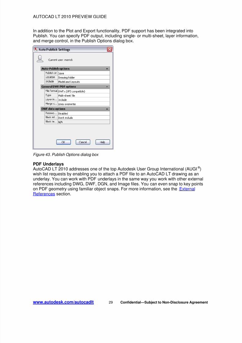
In addition to the Plot and Export functionality, PDF support has been integrated intoPublish. You can specify PDF output, including single- or multi-sheet, layer information,and merge control, in the Publish Options dialog box.
Figure 43. Publish Options dialog box
PDF UnderlaysAutoCAD LT 2010 addresses one of the top Autodesk User Group International (AUGI ® )wish list requests by enabling you to attach a PDF file to an AutoCAD LT drawing as an
underlay. You can work with PDF underlays in the same way you work with other externalreferences including DWG, DWF, DGN, and Image files. You can even snap to key pointson PDF geometry using familiar object snaps. For more information, see the ExternalReferences section.
www.autodesk.com/autocadlt 29 Confidential—Subject to Non-Disclosure Agreement
8/3/2019 AutoCAD LT 2010 - Preview Guide
http://slidepdf.com/reader/full/autocad-lt-2010-preview-guide 30/33
AUTOCAD LT 2010 PREVIEW GUIDE
Drawing File FormatAutoCAD LT 2010 introduces a new file format that offers improved save times, especiallywhen saving files with lots of annotative objects, along with several new features.
Improved File Navigation
File Navigation dialogs, such as Open and Save, now support auto-complete when typingfile names.
Figure 44. Auto-complete file names
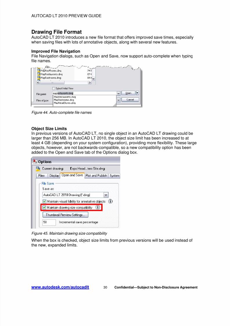
Object Size LimitsIn previous versions of AutoCAD LT, no single object in an AutoCAD LT drawing could belarger than 256 MB. In AutoCAD LT 2010, the object size limit has been increased to atleast 4 GB (depending on your system configuration), providing more flexibility. These largeobjects, however, are not backwards-compatible, so a new compatibility option has beenadded to the Open and Save tab of the Options dialog box.
Figure 45. Maintain drawing size compatibility
When the box is checked, object size limits from previous versions will be used instead ofthe new, expanded limits.
www.autodesk.com/autocadlt 30 Confidential—Subject to Non-Disclosure Agreement
8/3/2019 AutoCAD LT 2010 - Preview Guide
http://slidepdf.com/reader/full/autocad-lt-2010-preview-guide 31/33
AUTOCAD LT 2010 PREVIEW GUIDE
eTransmitThe eTransmit functionality has been enhanced to include a new option to “includeunloaded file references.” When this option is enabled, all unloaded reference files areincluded in the transmittal set but will remain unloaded in the eTransmit package. TheArchive functionality includes the same option to include unloaded file references and is
enabled by default.
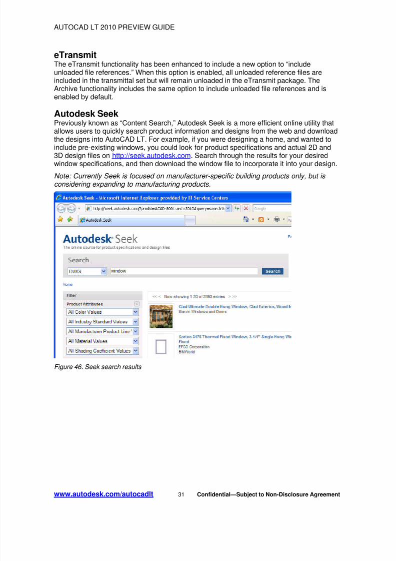
Autodesk SeekPreviously known as “Content Search,” Autodesk Seek is a more efficient online utility thatallows users to quickly search product information and designs from the web and downloadthe designs into AutoCAD LT. For example, if you were designing a home, and wanted toinclude pre-existing windows, you could look for product specifications and actual 2D and3D design files on http://seek.autodesk.com. Search through the results for your desiredwindow specifications, and then download the window file to incorporate it into your design.
Note: Currently Seek is focused on manufacturer-specific building products only, but is considering expanding to manufacturing products.
Figure 46. Seek search results
www.autodesk.com/autocadlt 31 Confidential—Subject to Non-Disclosure Agreement
8/3/2019 AutoCAD LT 2010 - Preview Guide
http://slidepdf.com/reader/full/autocad-lt-2010-preview-guide 32/33
AUTOCAD LT 2010 PREVIEW GUIDE
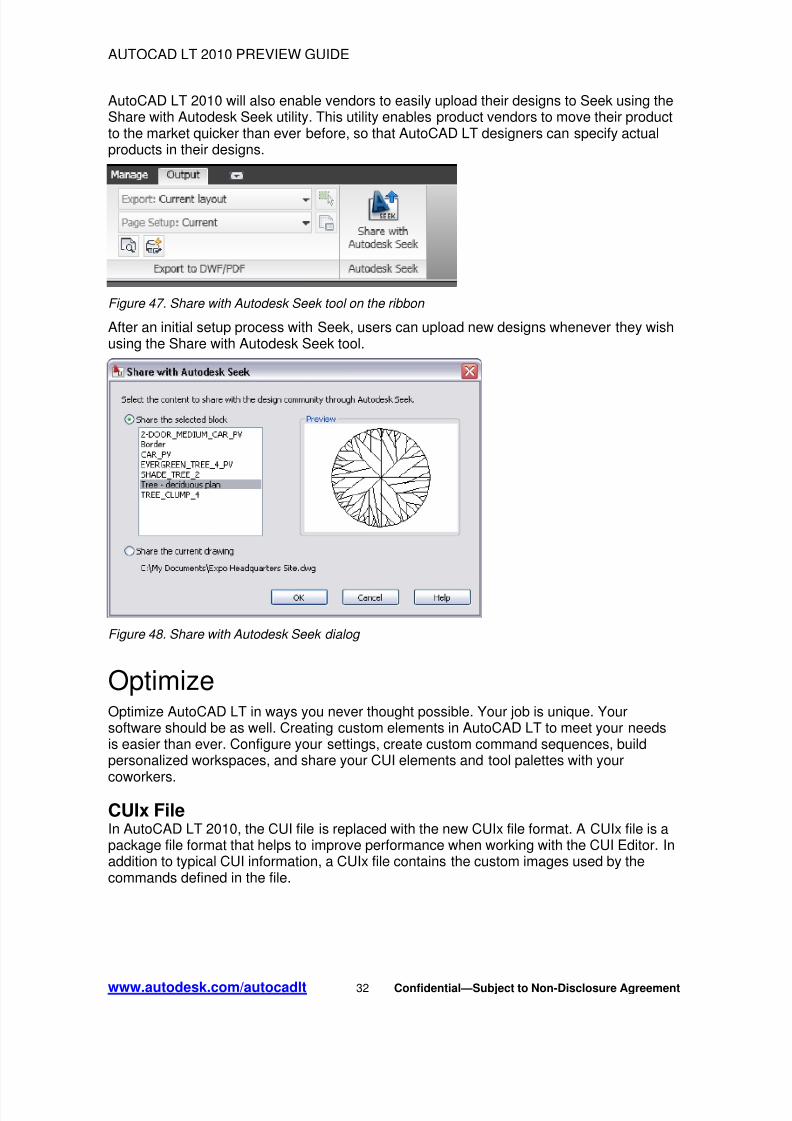
AutoCAD LT 2010 will also enable vendors to easily upload their designs to Seek using theShare with Autodesk Seek utility. This utility enables product vendors to move their productto the market quicker than ever before, so that AutoCAD LT designers can specify actualproducts in their designs.
Figure 47. Share with Autodesk Seek tool on the ribbon
After an initial setup process with Seek, users can upload new designs whenever they wishusing the Share with Autodesk Seek tool.
Figure 48. Share with Autodesk Seek dialog
OptimizeOptimize AutoCAD LT in ways you never thought possible. Your job is unique. Yoursoftware should be as well. Creating custom elements in AutoCAD LT to meet your needsis easier than ever. Configure your settings, create custom command sequences, buildpersonalized workspaces, and share your CUI elements and tool palettes with yourcoworkers.
CUIx FileIn AutoCAD LT 2010, the CUI file is replaced with the new CUIx file format. A CUIx file is apackage file format that helps to improve performance when working with the CUI Editor. Inaddition to typical CUI information, a CUIx file contains the custom images used by thecommands defined in the file.
www.autodesk.com/autocadlt 32 Confidential—Subject to Non-Disclosure Agreement

8/3/2019 AutoCAD LT 2010 - Preview Guide
http://slidepdf.com/reader/full/autocad-lt-2010-preview-guide 33/33
AUTOCAD LT 2010 PREVIEW GUIDE
Online License TransferAutoCAD LT 2010 includes a new Online License Transfer (OLT) utility that enables you tomove standalone licenses between computers. It replaces the Portable License Utility(PLU) used in previous Autodesk product releases. You can access OLT functionality fromthe License Transfer Utility option in the Start menu.
Figure 49. License Transfer Utility
From the License Transfer Utility, you can choose to export or import a license. Bothoptions require you to log in to Autodesk. You can export a license as either private orpublic. A private license can only be imported by the person that exported it. A publiclicense can be imported by any user running the same product and serial number.
SummaryWith AutoCAD LT 2010, you can create precise technical drawings with ease. Accuratelyand efficiently create, modify, and document your drawings. Enjoy compatibility andseamless communication with genuine DWG files. With powerful features and intuitivecommands, it’s no wonder AutoCAD LT is the professional choice.
Autodesk, AutoCAD, AutoCAD LT, AUGI, DWF, and DWG are registered trademarks or trademarks of Autodesk, Inc., and/orits subsidiaries and/or affiliates in the USA and/or other countries. All other brand names, product names, or trademarksbelong to their respective holders. Autodesk reserves the right to alter product offerings and specifications at any time without