automated can crusher project - tlee753.comtlee753.com/assets/docs/can-crusher-report.pdf · lee,...
TRANSCRIPT

Lee, Falcon, Fahey, Fleming, Freeman, Valdes 1
Automated Can Crusher Project Metal Recycling Solutions
Tyler Lee
Cole Falcon
Brendan Fahey
Brad Freeman
Max Fleming
Kyle Valdes

Lee, Falcon, Fahey, Fleming, Freeman, Valdes 2
Table of Contents
Cover Page ……………………………………………………………………………………. 1
Table of Contents ……………………………………………………………………………………. 2
Company Titles ……………………………………………………………………………………. 3
About M.R.S. ……………………………………………………………………………………. 4
Problem Statement ……………………………………………………………………………………. 5
Challenge ……………………………………………………………………………………. 6
Design Constraints ……………………………………………………………………………………. 7
Resource Materials ……………………………………………………………………………………. 8
Technology Sector Research ……………………………………………………………………………………. 9 - 11
Bill of Materials ……………………………………………………………………………………. 12
Inventory List ……………………………………………………………………………………. 13 - 14
Invention and Design Report ……………………………………………………………………………………. 15 - 16
Self-Evaluation (Tyler) ……………………………………………………………………………………. 17
Self-Evaluation (Max) ……………………………………………………………………………………. 18
Self-Evaluation (Cole) ……………………………………………………………………………………. 19
Self-Evaluation (Kyle) ……………………………………………………………………………………. 20
Self-Evaluation (Brendan) ……………………………………………………………………………………. 21
Self-Evaluation (Brad) ……………………………………………………………………………………. 22
Appendices Table of Contents……………………………………………………………………………………. 23
Appendices ……………………………………………………………………………………. 24 - 31

Lee, Falcon, Fahey, Fleming, Freeman, Valdes 3
Company Titles
President: Tyler Lee
Vice President: Cole Falcon
Chief Marketing Officer: Brendan Fahey
Research Manager: Kyle Valdez
Chief Operations Officer: Brad Freeman
Treasurer: Max Fleming
Lee, Falcon, Fahey, Fleming, Freeman, Valdes 4
About Metal Recycling Solutions
Our company is on the frontier for solutions involving aluminum can recycling, with
major breakthroughs in space saving technologies. We encourage innovations that involve
collaboration between premier robotic systems, advanced pneumatic actuating cylinders, and
superior control system programs to instill on the greatest quality and efficiency currently on
the market. Our mission is to provide environmentally friendly recycling in a more efficient
manner and to employ the use of jubilant minds in creative problem solving. We hope our
projects will impact you in a positive way at some point in the not too distant future!

Lee, Falcon, Fahey, Fleming, Freeman, Valdes 5
Problem Statement
How could aluminum cans be most efficiently reduced in volume so as to increase productivity
in recycling?

Lee, Falcon, Fahey, Fleming, Freeman, Valdes 6
Challenge
Design a pneumatic powered device that works in conjunction with a program logic interface
involving a robot to accurately transport cans from a cartridge based reloading system to the
crushing device which in turn will crush the cans and eject the result.
Lee, Falcon, Fahey, Fleming, Freeman, Valdes 7
Design Constraints
• Can Crusher device must be able to fit over the conveyer belt
• Can Crusher device must be able to allow robot claw to release can into crushing
chamber
• The Can Crusher must be able to crusher the entire can without fail
• Pneumatic actuator must be wired into the program controlled logic interface
• Robot must be programmed so as to repeat a cycle until all cans have been crushed
• Program must allow a delay long enough for solenoid to fully fire

Lee, Falcon, Fahey, Fleming, Freeman, Valdes 8
Resource/Materials
• Wood
• PVC Piping
• Plastic Tubing
• Aluminum Solenoid
• Electronic Solenoid Actuator
• Aluminum Wire
• Screws/nuts/bolts
• Tools and Machines in Engineering Lab

Lee, Falcon, Fahey, Fleming, Freeman, Valdes 9
Technology Sector Research
By Cole Falcon
Since industrialization took place, waste reduction and recycling have been two critical
parts of protecting our environment. Waste reduction is the process of minimizing your waste
output, usually by creating a better design or design procedure. Recycling is the process of
creating something new from something that has been used. Both waste reduction and
recycling are used to maximize efficiency and minimize wasted resources. In the manufacturing
industry, many different kinds of materials are recycled. Essentially anything that can still
function is reused. This applies to things such as electronic parts, packaging, fiber, cardboard,
wood, metal, glass, and textiles. Machines used for waste reduction in industry include
grinders, crushers, and shredders. Grinders are used to turn almost anything into dust, while
crushers and shredders are used for the size reduction of almost any material. Compactors are
used to dramatically reduce the size of large loads of waste, typically used on various types of
trash.
Waste management is a more recent problem due to an increase in human population
as well as industry. It was common for most waste to be turned to ashes and then released into
the ground, but some civilizations had larger waste output than others. The Mayans, for
example, has a monthly ritual where they would burn all of their waste in large dumps. After
industrialization, the Nuisance Removal and Disease Prevention Act of 1846 was passed,
starting the process of regulated waste management in London. Soon after the first incineration
Lee, Falcon, Fahey, Fleming, Freeman, Valdes 10
plant was opened in Nottingham to dispose of waste products. The earliest garbage trucks were
basic dump trucks pulled by horses. This was the beginning of modern waste disposal.
A more recent example of waste management is shown in Hong Kong, where their 3
primary landfills will be full within the next 5 years. They plan to build a waste to energy facility
in order to use the waste in a more effective manner. They also plan to implement odor and
pollution control equipment to prevent further harm to the environment as well as Hong
Kong’s inhabitants.
Recycling has many very positive effects, especially on the economy. Recycling creates
jobs, makes for more competitive manufacturing, and significantly improves the U.S. economy.
The total annual payroll of jobs connected to recycling adds up to billions of dollars. Recycling
also saves money by reducing the costs of waste disposal, such as landfills and incinerators. Not
only has recycling had an impact on the economy, but it has also had an impact on the
environment. Recycling significantly reduces pollution levels and carbon emissions. The overall
goal of recycling and waste reduction is to preserve natural resources, prevent the expansion of
landfills, and prevent further pollution.
One organization that has had a significant impact on the recycling field is Ceres.
Founded on March 24, 1989, Ceres was one of the main organizations trying to publicize the
risk of poor waste management, revealing just how significantly recycling can affect all aspects
of our life. They are located in Boston, Massachusetts. Ceres’s goal is to show the world that
recycling is critically important to us and our environment. One of the primary defeats faced by
Ceres is the United States’ rejection of the international Climate Change Treaty in 2001.
Although it was a large setback, the organization eventually recovered and began gaining
Lee, Falcon, Fahey, Fleming, Freeman, Valdes 11
ground. Ceres is a non-profit organization. Over the 25 years that Ceres has been established,
they have made important contributions to the recycling industry, especially making
sustainability reporting common practice. Currently, 93% of the world’s top 250 companies
now report their common practices.
Over time, recycling and waste reduction has had a significant positive impact on
society, industry, and the environment. With increasing global population and industry,
recycling has become a critical part of a clean planet. Thanks to clever operations and
applications, a rich history of the development of recycling technology, various impacts on the
human race, and organizations such as Ceres, recycling will likely keep our planet clean for
years to come.
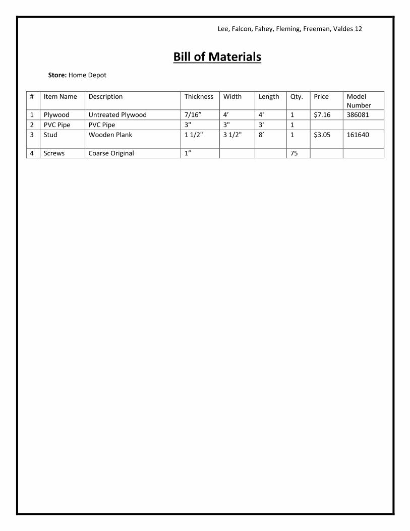
Lee, Falcon, Fahey, Fleming, Freeman, Valdes 12
Bill of Materials Store: Home Depot
# Item Name Description Thickness Width Length Qty. Price Model Number
1 Plywood Untreated Plywood 7/16” 4’ 4' 1 $7.16 386081
2 PVC Pipe PVC Pipe 3" 3" 3' 1
3 Stud Wooden Plank
1 1/2" 3 1/2" 8’ 1 $3.05 161640
4 Screws Coarse Original 1” 75

Lee, Falcon, Fahey, Fleming, Freeman, Valdes 13
Inventory List Number Name Description Length Width Height Quantity
1 Deltrol Controls
Resistor 1 1/4” 1 1/2” 2” 2
2 Tyco Circuit Boards
Electrical Control Center 3” 1 1/2” 1” 2
3 Large Solenoid
Can Smashing Solenoid 11 1/2”
1 3/4” 1
4 Air Tubing Pipe for Air Flow 20’ 1/4” 1
5 Black Wire Electrical Wire 20’ 1/16” 1
6 Blue Wire Electrical Wire 20’ 1/16” 1
7 PTFE Thread Seal Tape
Metal Pipe Joint Sealing Tape 43 1/3”
1/2” 1
8 Small Solenoid
Can Removing Solenoid 5” 7/16” 1
9 Mounting Bracket
90° Metal Fitting to Hold Small Solenoid to Wood
1 5/8” 1” 1 3/8” 1
10 Mounting Bracket
90° Metal Fittings to Hold Large Solenoid to Wood
2 1/2” 1 1/2” 1 7/8” 2
11 Air Control Fitting
Metal Block with Air Flowing through and Out at 90° Angle
5/16” 5/16” 3/4” 1
12 Rubber O-Rings
Rubber Rings to Seal Air Valves 1/4” 10
13 Air Output Fitting
Metal Fitting which Changes Air Output to Metal Pipe Fitting
1 5/8” 1/2” 1
14 Metal Washers
Metal Circles for Spacing 13/16” 2
15 Metal Pipe Fitting
Female to Female Metal Pipe Fitting for Air Flow
13/16” 1/2” 1
16 Air Nozzles Air Flow Nozzles to Connect Pipes 1” 1/8” 12
17 Air Input Fitting
Metal Fitting which Changes Air Input to Metal Pipe Fitting
1 1/4” 3/8” 3
18 Air Input Fitting
Metal Fitting which Changes Air Input to Metal Pipe Fitting
1” 9
19 On Switch Green Push On Switch 1 1/8” 1 1/8” 1 1/4” 1
20 Control Switch
Circuit Control Switch (1 and 2) 1 1/8” 3/8” 15/16” 1

Lee, Falcon, Fahey, Fleming, Freeman, Valdes 14
21 Off Switch Red Push Emergency Off Switch 1 1/2” 1 1/2” 2” 1
22 Control Switch
Circuit Control Switch (3 and 4) 1 1/8” 3/8” 15/16” 1
23 Directional Valve
Solenoid Directional Control Valve 7/8” 5/8” 2 1/4” 2
24 Mounting Bracket
Metal Piece to Join Solenoid Directional Control Valve to Wood
1 5/8” 1/2” 1/8” 2
25 Limit Switch On/Off Switch Changed When Hit 1/2” 1” 1/2” 5
26 Safety Cover Plastic Electrical Shielding for Electrical Components
2” 3/4” 5/8” 5
27 Time Delay Delay Switch 2” 2” 2 1/4” 1
Lee, Falcon, Fahey, Fleming, Freeman, Valdes 15
Invention and Design Report
Step 1 (Problem Statement): How could aluminum cans be most efficiently reduced in volume
so as to increase productivity in recycling?
Step 2 (Description of Research Collected): The majority of the research we found was based
on creating the prototype itself as such pneumatic devices only seem to exist on an industrial
scale and thus we were left to imaginations for creating our personal can crushing device. Thus,
our research came largely from Google images as a small source for inspirational ideas to
include, as well as from Ceres, a company that has shown promise in the field of recycling
innovations and seems to be able to have an impact in the environmental industry.
Step 3 (Possible Solutions): (See Appendices) Our first attempt at creating a prototype involved
a streamlined design which inevitably was inefficient. (Sketch A) The robot’s inability to reach
portions of the crusher was what made us scrap the project along with no involvement of the
robot claw. The second sketch (Sketch B) developed set the precedent for the final product as it
was the first to involve placing the can crusher over the conveyer belt so as to eject the final
crushed can onto the conveyer belt. Unfortunately the reason this design was not chosen is
because of the over complexity involving pressurizing the solenoids as well as inexact exit of the
can onto the conveyer belt was not precise enough to ensure this would work every time. The
final sketch created (Sketch C) is essentially the final product minus a few modifications made
during the construction process. The overarching idea was to take the ideas from Sketch B and
simplify them to create errorless device.
Step 4 (Final Design): The final design was decided upon largely due to its small structure and
involvement of the conveyer belt as the ejector system as shown in the photos. It also held the
advantage of being perpendicular to the robot so as to allow simple programming regarding the
vertices and lowering of the can into the crushing chamber. The final design works by lifting the
cans from a cartridge based loader and moving them to a PVC pipe chamber blocked on one
side with wood and the other by the head of the solenoid. In turn the program sends a signal to
the pneumatic actuator to fire the solenoid which crushes the can against the wood. After the
solenoid retracts, the can is then free to fall through a hole in the bottom of the structure onto
the conveyer belt, ready for further extraction. (See Appendices)
Step 5 (Development Work): (See Appendices) The schematic shown on page 28 is the simple
circuit involving the power source located on the program control unit, the electronic actuator
controlling the flow of air to the solenoid, and lastly the program control unit which is linked to
the computer. This circuit works by providing power to the actuator to reverse the flow of air
while being controlled by the computer. The inventor drawing (shown on page 29) is the final
Lee, Falcon, Fahey, Fleming, Freeman, Valdes 16
product constructed using Inventor 2010 and is correctly dimensioned. This 3-D object was then
used to provide the insight in manufacturing the final device. The program we used is also
copied in the appendix on page 27 and simply shows the steps the robot takes in grasping the
can, relocating it, dropping it into the can crusher, and then the can crusher crushing it.
Step 6 (Construction Description): The materials for this project were obtained via a kit derived
by Amatrol as the essential ingredients for such a project, as well as from materials originating
in the lab obtained from previous projects and orders from Home Depot. With these materials
the wooden framework was created with power tools such as a portable drill and band saw
which the solenoid and PVC pipe were then fitted to. When the time came to create the head
to be mounted on the solenoid for physically crushing the cans the initial impression was such a
part was to be designed on Autodesk Inventor and then printed on the Makerbot 3-D printer.
Instead, the finished head was cut out of wood and installed with additional hot glue to the
solenoid which was the only major change to the project.
Step 7 (Testing and Evaluation): Testing the robot included a vast amount of time programming
the robot to respond to commands and to consistently follow the same steps in relocating the
cans to the pneumatic powered crushing device. From here, the program was run hundreds of
times to ensure a quality sequence was performed despite any issues surrounding the cans
being slightly deformed in the process of gripping them with the robotic claw mechanism. One
slight flaw was found to exist in the wooden framework as a stud was not perfectly placed and
thus required addition use of a sawzall to remove the excess material preventing the cans from
dropping onto the conveyer belt. The results of testing allowed us to remove the remaining
errors and create a program which is both functional and efficient for an overall near perfect
machine. The only remaining area for improvement with such a device would be downscaling it
to fit large-scale manufacturing requirements, but as a prototype it fulfills its role to the initial
desire.
Lee, Falcon, Fahey, Fleming, Freeman, Valdes 17
Self-Evaluation
By Tyler Lee
As president of Metal Recycling Solutions, I found I had to deplore my experience in
many fields of engineering yet the most important aspect to completing the project was my
leadership role. By analyzing the skill sets of each individual, I delegated the tasks required to
accomplish our goal before the deadline so as to create a model of efficiency and dependability
for each member of my group. Tasks specific to me included construction of the physical can
crusher, wiring of the electrical components, creation of the design brief, overseeing company
attributes, programming the robot, and designing the PowerPoint presentation. In these
regards I believe that I was successful and enabled my group to accomplish the task at hand to
the best of my abilities.
Lee, Falcon, Fahey, Fleming, Freeman, Valdes 18
Self-Evaluation
By Max Fleming
As treasurer of our company, Metal Recycling Solutions, it was crucial that I monitored
the company budget, making sure that we could obtain all the necessary materials and do it for
less than 300$. Throughout the process of building the can crusher, I often assisted in the
construction of several parts needed for the completed product, such as the pneumatic can
crusher. This process required me to shape, and sand down a piece of wood that fit our original
design. When the construction process was finished, I worked with the company president,
Tyler, to wire the pneumatic cylinder, allowing it to move and crush the cans. As well as helping
in the construction process, I thought of ideas for a company logo, and helped graphically
design the logo. My group members also decided that I exemplified textbook drilling
procedures.
Lee, Falcon, Fahey, Fleming, Freeman, Valdes 19
Self-Evaluation
By Cole Falcon
As vice president of Metal Recycling Solutions, I would say that I played a crucial part in
the progress of our project. I played a hand in the designing of the company’s logo, and worked
together with Tyler to create our company name. In addition to this, I created the rough draft
for the Technology Sector Report. I also created a rough draft for our Design Brief. Although I
mainly created the written portions of the project, I also assisted in the construction of the Can
Crusher. This was mainly done by sanding pieces of the crusher that were nearing completion.
I also did my best to keep the members of the group on task and motivated. Overall, I feel that
my contributions to the group significantly helped in completing the project on time.

Lee, Falcon, Fahey, Fleming, Freeman, Valdes 20
Self-Evaluation
By Kyle Valdez
As Research Manager I was responsible for the assistance (along with the rest of my
group) to come up with a build materials list for our can crusher. Also I aided our president
Tyler in the building of the main structure of the crusher along with the programing of the
pneumatics system. Along with the programing I also contributed to the aid of the can crusher
as a whole in the construction process and post construction testing. I helped find several flaws
and correct these issues in the prototype.
Lee, Falcon, Fahey, Fleming, Freeman, Valdes 21
Self-Evaluation
By Brendan Fahey
As General Marketing Director of (I honestly forgot our company name) I had the role of
getting our company name out there. I designed the logo along with my fellow co-workers.
The robot programming process was carried out by Bradford Freeman and myself. I helped the
construction by sanding, cutting, and applying necessary parts for the success of the “can
crusher.” I also contributed cans for the testing process of our product.

Lee, Falcon, Fahey, Fleming, Freeman, Valdes 22
Self-Evaluation
By Brad Freeman
My contribution to the project was largely in assistance with minor research details for
cost analysis and secondary initial programmer of the robot. This project enabled me to
envision the powerful results of a career in engineering and the possibilities that are invoked by
such a broad spectrum of subject areas associated with the field in general. Developing the
initial program entailed my knowledge of robotic programming gained from completing the
Amatrol lab and while this program was scrapped it did provide the foundation for the final
project. Overall, while engineering may not be my pathway, I did gain valuable insight from
working on this task and look forward to similar future engagements.
Lee, Falcon, Fahey, Fleming, Freeman, Valdes 23
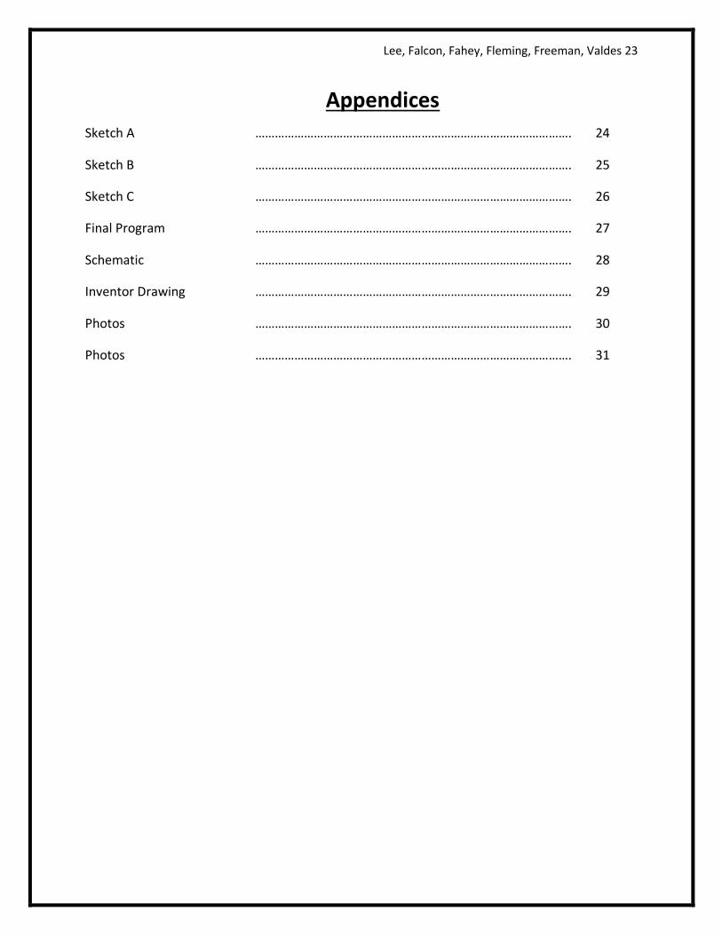
Appendices
Sketch A ……………………………………………………………………………………. 24
Sketch B ……………………………………………………………………………………. 25
Sketch C ……………………………………………………………………………………. 26
Final Program ……………………………………………………………………………………. 27
Schematic ……………………………………………………………………………………. 28
Inventor Drawing ……………………………………………………………………………………. 29
Photos ……………………………………………………………………………………. 30
Photos ……………………………………………………………………………………. 31