automatic battery replacement system for uavs: …xs3d.kaist.ac.kr/paperdata/2011/automatic.pdf ·...
TRANSCRIPT

ICUAS manuscript No.(will be inserted by the editor)
Automatic Battery Replacement System for UAVs:Analysis and Design
Koji A. O. Suzuki · Paulo Kemper F. ·James R. Morrison
Received: February 15, 2011 / Accepted: April 3, 2011
Abstract Future Unmanned Aircraft Systems (UAS) are expected to benearly autonomous and composed of heterogeneous Unmanned Aerial Vehicles(UAV). While most of the current research focuses on UAV avionics and controlalgorithms, ground task automation has come to the attention of researchersduring the past few years. Ground task automation not only relieves humanoperators, but may also expand the UAS operation area, improve system cov-erage and enable operation in risky environments without posing a threat tohumans. We propose a model to evaluate the coverage of a given UAS. Wealso compare different solutions for various modules of an automated batteryreplacement system for UAVs. In addition, we propose a ground station ca-pable of swapping a UAV’s batteries, followed by a discussion of prototypecomponents and tests of some of the prototype modules. The proposed plat-form is well-suited for high-coverage requirements and is capable of handlinga heterogeneous UAV fleet.
Keywords Unmaned Aerial Vehicles · UAVs · Autonomous ConsumableReplacement · Service Station · Enabling Technologies · Autonomy
K. A. O. SuzukiKAIST Mechanical Engineering DepartmentTel.: +82-42-350-3167E-mail: [email protected]
P. Kemper F.KAIST Electrical Engineering DepartmentTel.: +82-42-350-3167E-mail: [email protected]
J. R. Morrison (�)KAIST Industrial and Systems Engineering DepartmentTel.: +82-42-350-3167E-mail: [email protected]

2 Koji A. O. Suzuki et al.
1 Introduction
The United States Federal Aviation Administration (US FAA) defines an Un-manned Aircraft System (UAS) as a collection of Unmanned Aerial Vehicles(UAV), control station(s), command and control algorithms and equipment forlaunch, recovery, communication and navigation [1]. While many efforts havebeen directed to the study of these components, there has been significantlyless attention paid to the automation of ground maintenance tasks. While suchactivities may be relegated to humans, to achieve a UAS with greater range,applicability and autonomy, such efforts must be automated.
Initial ground breaking work in this area has recently been conducted. In[2], the first prototype of a battery recharge platform for UAVs was developedto support the RAVEN UAS test bed. To our knowledge, the authors in [3] arethe first to study and provide an analytic answer to the question of whethera battery charging or replacement platform is preferable. They also developedand compared various recharge station designs and proposed a conceptualreplacement platform. Simultaneously and independently of [3], [4] developedthe first prototype of a UAV battery replacement system as part of their ACEtest bed. They also developed management software to support the process ofoperating UAVs with such a platform and an off-UAV method to deduce whena battery requires service. The prototype efforts for UAVs follow related workfor ground based robots in [5–11] for battery charging and [12,13] for batteryreplacement.
There has also been some work to automate ground tasks for gas poweredUAVs [14], where UAV precision landing capability, automated capturing andcentering mechanisms that move UAVs to a proper refueling position weretested.
Despite these advances, numerous opportunities remain. First, the analysisof [3] is based on bounds so that there is an opportunity to tighten the results.Second, while most of the proposed solutions for ground based service stationsrely on homogeneous fleets of UAVs, it is anticipated that the UASs of thefuture will be heterogeneous [15]. Third, service stations should be robustto environmental factors that compromise the integrity of UAV positioningsystems; existing designs are intended primarily for laboratory based test beds.Fourth, there is a need to consider additional design choices for the componentsof service stations to improve system reliability and performance.
In this paper, we strive to address these needs for battery operated UAVsystems. The contributions and organization are as follows:
– The paper develops Petri net models of battery charging and replacementsystems that enable a tight comparison between them. (Section 2)
– The paper develops and compares design options for the functional com-ponents of battery replacement service stations. These attempt to addressthe issues of fleet heterogeneity and UAV landing control robustness. (Sec-tion 3)
– The paper reviews and conducts operational testing of key components ofa system prototype. (Section 4)

Automatic Battery Replacement System for UAVs: Analysis and Design 3
PlatformReady for
UAV
P4
TR
TF
UAV
TI
TC
Battery
Waiting
to fly
P2
Ready
to fly
P3
Battery
depleted
P1
PlatformReady for
UAVP4
TR
TF
UAV
TI
Waiting
to fly
P2
Ready
to fly
P3
Battery
depleted
P1
Battery
Ready to
Charge
P5
Battery
charged
P6
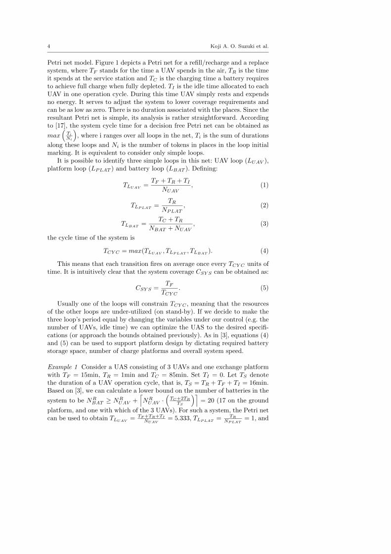
Fig. 1 Petri Net model. The left-hand side models a refill/recharge system, and the right-hand side models a replace system
Concluding remarks are presented in Section 5 and future work is presentedin Section 6.
2 Planning UAS
A Petri net can be considered a graphical tool that may be used to describe dis-tributed, concurrent, parallel, asynchronous, deterministic and/or stochasticstepwise processes [16]. It is a bipartite graph, in which the nodes are dividedinto transitions (T, represented by bars) and places (P, represented by circles).The connection between nodes is made by directed arcs, which connect only aT to a P, or a P to a T, never P to P or T to T. Tokens (usually representedby dots) travel through the net. Whenever there is a token at the input ofall arcs leading to a transition, the transition “fires”, the tokens at the inputare consumed and a token is created at the output of each of the outgoingarcs. The event of a firing can happen concurrently and can overlap in timewith other firings so long there are enough tokens to fire a transition. Thelocation and number of tokens at the start of the Petri net evolution is calledthe initial marking. Times may be associated with the transitions and places.Tokens entering a node must wait for this duration before they are released.
If there is only one output arc and one input arc at any of the places of agiven Petri net, the network is called “decision-free” [17]. The cycle time of adecision-free Petri net is straightforward to analyze without much computa-tional effort.
For simplicity, we assume that there are a sufficient number of chargersto support the system. Thus we do not consider chargers as a resource in our
4 Koji A. O. Suzuki et al.
Petri net model. Figure 1 depicts a Petri net for a refill/recharge and a replacesystem, where TF stands for the time a UAV spends in the air, TR is the timeit spends at the service station and TC is the charging time a battery requiresto achieve full charge when fully depleted. TI is the idle time allocated to eachUAV in one operation cycle. During this time UAV simply rests and expendsno energy. It serves to adjust the system to lower coverage requirements andcan be as low as zero. There is no duration associated with the places. Since theresultant Petri net is simple, its analysis is rather straightforward. Accordingto [17], the system cycle time for a decision free Petri net can be obtained as
max(
Ti
Ni
), where i ranges over all loops in the net, Ti is the sum of durations
along these loops and Ni is the number of tokens in places in the loop initialmarking. It is equivalent to consider only simple loops.
It is possible to identify three simple loops in this net: UAV loop (LUAV ),platform loop (LPLAT ) and battery loop (LBAT ). Defining:
TLUAV=
TF + TR + TI
NUAV, (1)
TLPLAT=
TR
NPLAT, (2)
TLBAT=
TC + TR
NBAT + NUAV, (3)
the cycle time of the system is
TCY C = max(TLUAV, TLPLAT
, TLBAT). (4)
This means that each transition fires on average once every TCY C units oftime. It is intuitively clear that the system coverage CSY S can be obtained as:
CSY S =TF
TCY C. (5)
Usually one of the loops will constrain TCY C , meaning that the resourcesof the other loops are under-utilized (on stand-by). If we decide to make thethree loop’s period equal by changing the variables under our control (e.g. thenumber of UAVs, idle time) we can optimize the UAS to the desired specifi-cations (or approach the bounds obtained previously). As in [3], equations (4)and (5) can be used to support platform design by dictating required batterystorage space, number of charge platforms and overall system speed.
Example 1 Consider a UAS consisting of 3 UAVs and one exchange platformwith TF = 15min, TR = 1min and TC = 85min. Set TI = 0. Let TS denotethe duration of a UAV operation cycle, that is, TS = TR + TF + TI = 16min.Based on [3], we can calculate a lower bound on the number of batteries in the
system to be NRBAT ≥ NR
UAV +⌈NR
UAV ·(
TC+2TR
TS
)⌉= 20 (17 on the ground
platform, and one with which of the 3 UAVs). For such a system, the Petri netcan be used to obtain TLUAV
= TF+TR+TI
NUAV= 5.333, TLPLAT
= TR
NPLAT= 1, and

Automatic Battery Replacement System for UAVs: Analysis and Design 5
TLBAT= TC+TR
NBAT−NUAV= 5.059. Thus TCY C = TLUAV
and CSY S = TF
TCY C=
2.8125 UAVs/unit time. If we want a lower coverage with the same system,
say 2.5, we can increase TI . Setting TI = (TF + TR) ·(
NRUAV ·CUAV
CTGTSY S
− 1)
= 2
min, the minimum number of batteries in the system remains the same andTCY C = 6 min. We then have CSY S = 2.5 UAVs/unit time.
3 Design Options
In this section we discuss design options for an autonomous UAV battery re-placement system ground station. This station is to automatically swap thedepleted batteries of a UAV for a recharged battery without human interven-tion. Here, instead of tackling navigation control algorithm problems, we workwith design parameters to solve issues such as:
– Guiding the UAV to the battery replacement site,– Orienting the UAV in a desired direction,– Locking the UAV position on the station,– UAV-battery connections: extracting and placing a battery in the UAV,– Battery transportation, and– Battery array recharging.
The functions required are capture and release of the UAV, removal ofbattery, battery transportation, battery charging and battery replacement.
3.1 UAVs, batteries and charging
UASs composed of different types of UAVs are of interest to both civil andmilitary applications [15]. It is desirable that service stations provide serviceto as many different kinds of UAVs in the UAS as possible. This may serve toreduce the number of ground stations and promote an even spread of the cov-erage of a given UAS. Since Lithium-polymer (Li-Po) battery-powered UAVsare popular due to the high energy density of Li-Po batteries[18], we electedto design a system that can serve UAVs with two-cell and three-cell Li-Pobatteries. Li-Po batteries require a balanced charger [18] and many of thecommercially available hobby chargers are already designed to charge two-celland three-cell batteries. This decision primarily affects the geometry of theelectric terminals and minimizes charging logic complexity.
A popular UAV employing this Li-Po battery is the Lama V3/4 [19]. Itwas used in the Autonomous Control Environment (ACE) test bed at [4]. TheLama V3/4 is a coaxial, small remote control helicopter helicopter designedand manufactured by E-Sky. It is primarily for hobbyists and is easy to fly.The main rotor diameter is 340mm, body weight of 230g (with OEM battery)and the OEM power supply is a 2-cell Lithium Polymer battery pack (7.4V800mAh). Such UAVs are usually relatively inexpensive, simple, light andsusceptible to weather conditions.

6 Koji A. O. Suzuki et al.
UARTModule
RX TX
Main Control
unitUART
ModuleRX TX
Charger001
UARTModule
RX TX
Chargern
UARTModule
TX RX
UARTModule
TX RX
Charger002
Chargern-1
Fig. 2 Communication network topology between chargers and main control unit
The HoneyBee King 2/3/4 [20] is an example of a UAV using a three-cellLi-Po battery. Following a more traditional helicopter design, the HoneyBeeKing has a main rotor and a tail rotor to control the UAV. The main rotordiameter is 600mm, body weight of 470g (with OEM battery) and the OEMpower supply is a 3-cell Lithium Polymer battery pack (11.1V 1000mAh). SuchUAVs are typically more robust with greater capability than their smallercounterparts but require more skill to control.
As seen in [3], systems with expensive UAVs (including attached equip-ment) are better served by battery replacement systems. Therefore, systemswhich are capable of swapping the batteries of the UAVs are needed for larger,heterogeneous UASs and we will focus on the design of service stations for thispurpose.
Despite very high energy density, Li-Po batteries require special care forrecharging [18]. Cycle aging also reduces the maximum charge capacity ofa battery [18] [21]. These facts together demand smart battery chargers toensure battery safety and maximal usability throughout the battery lifetime.Therefore, we elected to use smart off-the-shelf battery chargers and rely onthe “fully charged” signal from such a charger. The downside is that a smallcommunication network between chargers and the main control is needed. Thisapproach is different than the time-estimation approach used by [4], where thecharger is turned on for a given amount of time, then turned off regardless ofthe real status of the battery. However, the possibility of using batteries attheir maximum justifies the hardware complexity of a smarter system. Not tomention that time-estimation does not address the failure of batteries, whereasa smart charger can identify such situation.
Figure 2 depicts the basic topology of the communication network be-tween the main control and chargers. Designing the microcontrollers behindeach charger and the main microcontroller to have a universal asynchronousreceiver/transmitter (UART) or other equivalent serial communication periph-eral, one can design a ring network very easily. When a battery is ready orfaulty, the charger responsible for that battery sends such information ad-dressed to the main control. The main control can also request status fromany charger by just sending a packet address to that charger. When a chargerreceives a message which is not addressed to it, it forwards it to the next

Automatic Battery Replacement System for UAVs: Analysis and Design 7
charger. The main control never forwards any message. In this fashion, theburden of keeping track of the batteries is relieved from the main control unit,where it can focus in the battery changing tasks and communication to theUAS main control.
3.2 UAV positioning methods
Batteries are held in a specific position on the UAV. To be able work withthem, one should position the UAV in a specific place after it has landed oridentify its location. Precision landing systems were required in [2] and [4].[3] focused on how to address small errors in landing by increasing the UAVcapture area during landing.
The design options presented in this paper assume that the ground stationsare outdoor, where weather conditions cannot be predicted. The focus hereis not on landing algorithms, but on how to address UAV positioning afterlanding with small error. While UAV navigation systems are assumed to exist,we will allow landing position error. The goal is to allow the UAV to reach thelocation where battery swapping will be conducted, even if its landing positionis non ideal due to navigation errors, weather conditions, UAV damage, etc.
The design options related to UAV positioning which we judge to be pos-sible are depicted in Figure 3. Figure 3 A shows a donut shaped platform thatincreases the possible capture area of the UAV during landing. If the UAVlands within the boundaries of the donut, it slides and will be guided towardsthe center of the platform, where the battery change occurs. If it lands outside,it will slide outward without damaging the UAV.
To increase the area where the UAV can land, we also considered flatsurface designs. The UAV simply lands and is guided toward a specific locationon the platform where the battery swapping occurs [3]. Figure 3 B shows aUAV centering mechanism in which four arms are pinned to four differentpoints in a flat surface. These arms lie in different heights to avoid collisionbetween each other and can be actuated individually by one motor each orby one single motor using a pulley and cable actuation to close the arms. Toreturn the arms to their original position, torsional springs can assist. The toppart of Figure 3 B shows four arms in an open/resting state. After the arrivalof the UAV, the main controller closes the arms so that the UAV is pushedtowards the center of the platform as shown in the bottom part of Figure 3 B.
The design depicted in Figure 3 C is also based on a flat platform withincreased landing area to accommodate landing errors. The target again is tomove the UAV to the center of the platform, where battery swapping will takeplace. Now, instead of solid arms, pulleys and cables are used. The platformwill have cleft guides radiating from the center to the edge of the surface plate,where slides will be placed (the six pairs of lines leading from the central circlein Fig. 3C). These slides can be moved radially, by radial actuation. On theinterior of each slide, two pulleys are placed and on the outward part of theplatform, two more pulleys are placed (in this case, a hexagon is used, thus 12

8 Koji A. O. Suzuki et al.
Fig. 3 Design options for UAV positioning system
pulleys are fixed on the outward part). The cables pass through the pulleys ina way that one motor can tension the pulleys, forcing them to move radiallytowards the center of the platform, while other motor causes cable tension tomove the pulleys outward. The outward resting position can be seen on the toppart of Figure 3 C. When the UAV lands on the flat surface, the main controllerturns on the motor tensioning the cable of the radially movable pulleys. Thepulleys will then slide towards the center of the platform, dragging the UAVto the center position.
3.3 Skid changes or add ons
In order to swap a UAV battery, there is a need for a more dynamic battery-UAV coupling system, a fast battery capturing device as well as a simpleUAV positioning system. To achieve these requirements, changes to the UAVare necessary, as original equipment manufacturer (OEM) skids and chassis donot comply with the system needs. For example, lets say that the UAV is beingguided by four arms symmetrically pushing the UAV towards a center platformas shown in 3 B. It will be more convenient for our design if the geometriccenter of the UAV skids and battery are aligned. There are two options if theOEM UAV skids or chassis are not suitable. Either new skids can be designedto fit our necessities or add on parts to the skids/UAV chassis can be used.New skids can come with optimized weight, probably costing more than justadding extra parts. By placing add ons, the weight of the UAV will increase,affecting its payload capacity from one side, but can be extremely versatile
Automatic Battery Replacement System for UAVs: Analysis and Design 9
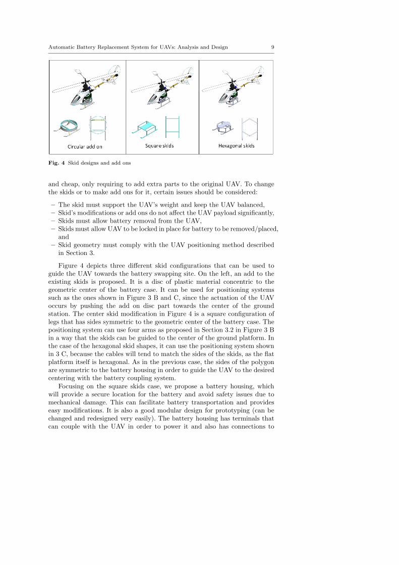
Fig. 4 Skid designs and add ons
and cheap, only requiring to add extra parts to the original UAV. To changethe skids or to make add ons for it, certain issues should be considered:
– The skid must support the UAV’s weight and keep the UAV balanced,– Skid’s modifications or add ons do not affect the UAV payload significantly,– Skids must allow battery removal from the UAV,– Skids must allow UAV to be locked in place for battery to be removed/placed,
and– Skid geometry must comply with the UAV positioning method described
in Section 3.
Figure 4 depicts three different skid configurations that can be used toguide the UAV towards the battery swapping site. On the left, an add to theexisting skids is proposed. It is a disc of plastic material concentric to thegeometric center of the battery case. It can be used for positioning systemssuch as the ones shown in Figure 3 B and C, since the actuation of the UAVoccurs by pushing the add on disc part towards the center of the groundstation. The center skid modification in Figure 4 is a square configuration oflegs that has sides symmetric to the geometric center of the battery case. Thepositioning system can use four arms as proposed in Section 3.2 in Figure 3 Bin a way that the skids can be guided to the center of the ground platform. Inthe case of the hexagonal skid shapes, it can use the positioning system shownin 3 C, because the cables will tend to match the sides of the skids, as the flatplatform itself is hexagonal. As in the previous case, the sides of the polygonare symmetric to the battery housing in order to guide the UAV to the desiredcentering with the battery coupling system.
Focusing on the square skids case, we propose a battery housing, whichwill provide a secure location for the battery and avoid safety issues due tomechanical damage. This can facilitate battery transportation and provideseasy modifications. It is also a good modular design for prototyping (can bechanged and redesigned very easily). The battery housing has terminals thatcan couple with the UAV in order to power it and also has connections to

10 Koji A. O. Suzuki et al.
Fig. 5 Battery case design for magnetic couplers
match with the charger in the ground station. A possible design of a batterycase is depicted in Figure 5. Projection views of a battery case are shown onthe left and the isometric view of a possible skid assembly can be seen at theright. At the bottom and at the right views of the battery case, ferromagneticplates are placed with the intent of using an electromagnet to actuate it inother systems (see Sections 3.6 and 3.7).
3.4 Battery and UAV connecting system
Normally, batteries are connected to UAVs via wire plugs and placed inside theUAV, thereby, ensuring terminal connection and battery stability. However, ina platform that has to rapidly swap a UAV’s depleted battery for a rechargedone, such a connection/holding system is not suitable. The method by whichthe battery is secured and physically connected to the UAV is of great impor-tance because it will effect the repeatability, complexity, and the time that theground station will take to swap batteries. Also, the added weight will effectthe UAV’s payload and flight time.
In order to create the interface between UAV and platform, mechanicaland magnetic couplers are considered and devices that can easily hold andrelease batteries while ensuring terminal connections in a UAV are proposed.
3.5 Mechanical and magnetic couplers
A battery holding system in a UAV must be low in weight, securely hold thebattery during flight, resist small impacts (such as small drops), maintain thebattery and UAV terminal connections, and allow easy insertion and extractionof the battery when necessary. To do so with mechanical components, a simplemodel can be employed.

Automatic Battery Replacement System for UAVs: Analysis and Design 11
Fig. 6 Model of battery insertion in mechanical and magnetic coupler
Fig. 7 Example of mechanical coupler with matching battery case
Figure 6 A depicts a mechanical coupler model in which a battery is forcedupward against the lower angled surface of spring assisted latch devices (thesymmetric arrow-shaped pins). This actuation generates a force in the latchdevice, whose horizontal component will contract the spring allowing the bat-tery to pass through the mechanism. When the battery finally reaches the end,it does not compress the springs anymore and the spring of the latch devicewill force the battery upward, guaranteeing the electric contact of UAV andbattery terminals during flight.
Figure 7 shows an example of mechanical coupler for a battery case tomatch the UAV. It consists of leaf spring latches that have angles on the ends.When actuated upward, the latches bend, allowing the battery to pass throughthe spring. Since the battery case has matching indentations on its sides, itallows the spring to lock the battery case in place.

12 Koji A. O. Suzuki et al.
Instead of using moving parts as in a mechanical lock, neodymium mag-nets can be used (Figure 6 B). These magnets can provide similar holdingcharacteristics as a mechanical coupler. If the magnets are used as interfaceterminals between the UAV and battery, then it becomes a more versatileplug-and-play terminal auto-guiding system. This approach was used in [4],where neodymium magnets were set in a fiberglass battery casing and in anESky LAMA V4 helicopter’s belly to establish terminal match and coupling.In that system, a servo motor rotates the battery case in order to cause shearin the magnets and allow battery disengagement from the UAV.
Figure 6 B shows a straightforward procedure of coupling and terminalmatching. By simply moving the battery toward the UAV, which both possessmagnet terminals, the fixed UAV will attract the battery to it, forcing terminalmatch. Magnet polarity on the terminals can be inverted to ensure only onelocking position.
Magnets are very versatile, but they have disengagement problems againstshearing forces and impact. Also, if they are used as terminals, they may at-tract metallic bodies that may cause short-circuits. Adding magnets to allbatteries in a system is a good idea to ensure terminal connection and locking.However, it may cause problems in battery transportation because the batter-ies may attract each other and cause unwanted terminal contact (which canbe very undesirable for Li-Po batteries). Another issue is the total number ofmagnets in the system; too many may increase overall system cost. In addi-tion, neodymium magnets are very brittle, and if they are released to matchfrom a distance, they may break upon collision.
Although magnets on both the UAV and battery can enable easy matching,there are disadvantages as discussed previously. An option to reduce the useof magnets is to use them only in the UAVs and replace the ones in batteriesfor sheet metal ferromagnetic terminals.
To steer clear of the possible short-circuit issues, a male-female plug con-nection is proposed. This type of connection allows a physical “wall” to staybetween the terminals, and even if metallic parts are attracted to them, theprobability of short-circuits is reduced. This design option is depicted in Figure8. The top left figure shows male connectors in the front view of the batterycase, while the top center figure provides a cut view of the UAV module toshow the female plugs and terminals. The terminals plus (+) and minus (-) inthe battery case are the terminals that will power the UAV when connectedto it, while all four of them (given this 3 cells battery) will be used to rechargethe battery when it reaches the recharging platform. The terminals plus (+)and minus (-) in the UAV module are the UAV terminals, while 1 and 2 areonly magnets that help to secure the battery case in the correct position.
3.6 Battery capturing system
Another important system in the design of an automatic battery swappingmachine is the method to secure a battery for transportation and how to

Automatic Battery Replacement System for UAVs: Analysis and Design 13
Fig. 8 Battery case and UAV module assembly in UAV skids
safely insert and extract batteries from the UAVs . The required systems area battery capturing device and a battery transportation method from UAV toswapping site. We consider only mechanical and electrical options.
The battery capturing system has only one function: prevent the batteryfrom movement in any direction relative to the capture device or “grabber”.We considered a mechanical claw, servo-assisted magnets and electromagnets.Mechanical devices require guidance and positioning in order to clamp thebattery and pull it out of the UAV. This sort of system demands use of physicalspace to open and close arms, has many moving parts (is thus more proneto failure) and may require tight tolerances to ensure assembly and guidemovements. Electromagnets could also be used as a capturing system. Theyare easy to control and have high repeatability, although a ferromagnetic platemust be attached to the battery case, increasing on board weight. A servo-assisted permanent magnet was used in [4] to extract the battery from theUAV. It is also an option to use magnets on both sides of the UAV/batteryinterface. Such a system does not use a servo-motor at all times, and so, small

14 Koji A. O. Suzuki et al.
Fig. 9 In A, an electromagnet being actuated on a table vertically. In B, the electromagnetreaches the battery case and is turned on, capturing the battery from the UAV. In C, thetable is actuated downward and the battery case is extracted from the UAV.
amounts of current are required. However, it has moving parts and magnetsmay attract foreign bodies, causing short-circuits in the system.
We propose a capturing system with one electromagnet to remove thebattery case from the UAV.
In Figure 9 A, the UAV is assumed to have reached a specific position.At the bottom of the UAV, there is a battery case, which is being held byeither mechanical coupling or by magnets, as described in the previous chapter.At the bottom of the battery case, there is a ferromagnetic metallic plate.The capturing system moves vertically via an elevator and the electromagnetis activated when necessary. The system moves upward until it reaches thebottom of the battery case metallic plate. As shown in 9 B, the electromagnetis then turned on and thereby securely attaches to the battery case. As seenin 9 C, the elevator pulls the electromagnet down, resulting in battery caseextraction from the UAV. This approach is different from the one in [4], thatinstead uses shearing forces to separate the magnets. Due to our approach,either mechanical or magnetic couplers can be used to secure the battery caseto the UAV.
3.7 Battery transportation method from UAV to swapping site and batterystorage system
As seen in Section 3.6, there is a need to transport the depleted battery andcase to the swapping site, where a recharged battery can be obtained. In orderto charge the depleted batteries, a charger array is required. In our proposeddesign, each charger has a housing that matches the battery case geometry.It must have terminal interfaces that can connect the battery case terminalswith the charger ones. The chosen design for the elevator was a vertical scissorelevator that can extract the battery and the case from the UAV, deliver thebattery to the battery supply site, and return the case and recharged batteryback to the UAV.

Automatic Battery Replacement System for UAVs: Analysis and Design 15
The charger array design chosen was a circular array of chargers that feedthe elevator: a battery magazine. To connect these two systems, a rack andpinion system is proposed for the battery and case transportation that removesthe battery from the charger array and delivers it to the elevator and viceversa. The rack has another electromagnet on the actuating end. It will holdthe battery case while being transported.
The systems described in this section are depicted in Figure 10. Figure10 A provides information about the system parts. Initially, the UAV is tobe guided to a fixed place, where the elevator can access the battery case. InFigure 10 B, the depleted battery is assumed to have reached the swappingsite, at the center of the circular platform. The battery is being held on thetop of the elevator by an electromagnet (as seen in Section 3.6). The chargerarray positions a magazine cell containing a charged battery in alignment withthe rack and pinion system. The electromagnet at the tip of the rack will turnon and the rack will be actuated. The charged battery is pushed toward thedepleted battery by the rack, and together they move until the used batteryreaches the buffer zone, marked with the sign “-”. The rack then retracts(leaving the old battery in the ”-” position until the fully charged batteryand case are positioned on the elevator. The rack electromagnet is turned off,thereby releasing the new battery and case. The rack retracts further to clearthe elevator operation area. In 10 C, while the elevator raises the new batteryto the UAV, the rack system captures the depleted battery from the buffer andplaces it in the charger magazine, initiating charging of the depleted battery.
3.8 Battery storage system options and consequences of design choices
The place where the battery will be stored for charging is of great importancefor the system. It is directly related to the way that the battery will be trans-ported back to the UAV as well as how the chargers will be connected to thepower line. The options proposed are:
– One or more circular arrays of batteries to be used as a magazine,– X-Y axis array of batteries, and– X-Z axis array of batteries.
The circular array, depicted in Figure 11 is not space efficient; the centerpart is not used. There are complications in connecting the chargers, since thedisc will spin, and simple wire connections may be caught in the assembly. Asthe batteries are arranged in a circular array, access to batteries is simple andmay be more energy efficient. There is a need only for one actuator to spin thedisc, and another to swap batteries from the assembly. As the disc only spins,it is easier to control when compared to a two axis system.
The linear arrays are very space efficient, because a grid of battery chargerscan be organized easily and side-by-side. Since it is a static system, wiring ispossible, making it easy to make charger connections with the station. Thereis a need for precise actuation and linear guides in at least two axes, in order

16 Koji A. O. Suzuki et al.
Fig. 10 In A, swapping system components are shown. In B, the rack and pinion actuationsystem places the depleted battery in the buffer zone, while releasing the charged batteryin the swapping zone. In C, the charged battery is actuated to the UAV, while the rackretrieves the depleted battery from the buffer and places it inside the charger magazine.
Fig. 11 Magazine of batteries in a circular array of chargers actuated by rack and pinionsystem.
to find the correct battery position in the charger array. This will increasecontrol algorithm complexity, when compared to the circular array design.Figure 12 depicts one possible implementation of such a linear array in anX-Y orientation. A rectangular X-Z array can also be similarly conceived.

Automatic Battery Replacement System for UAVs: Analysis and Design 17
Fig. 12 Batteries in a matrix array of chargers accessed by a small gantry crane.
3.9 Elevator design option for UAV vertical transportation
There are other options to deliver the battery case to the swapping site, otherthan moving the battery after extracting it from the UAV. One is to lower theentire UAV, and at the swapping site, exchange batteries with the UAV, asdepicted in Figure 13. Such a system may reduce complexity of the batteryholding device, allow battery extraction from the front part of the UAV andminimize UAV modifications. As a con, the number of floors of the circularbattery array discs cannot be increased easily, since the UAV must be ableto drop low enough to reach each array once a more complicated system isrequired. Also, the amount of force required from the elevator will be increased,since the entire UAV is elevated.
4 Prototype
We next discuss module prototypes developed to learn the failure modes andmeasure robustness to continuous operation. Considering that a deployed sta-tion is expected to operate without human assistance for a long time, wedesigned many of the parts to operate under loose tolerance specificationsto account for eventual wearing. Most of the parts were manufactured withlaser-cut acrylic to simulate loose tolerance and unpredicted wearing. Success-ful operation of the system under loose tolerance conditions suggests that the

18 Koji A. O. Suzuki et al.
Fig. 13 In A, UAV is lowered to the swapping site. In B, the depleted battery is extractedstraight out of the UAV. In C, a new battery is actuated in the UAV after magazine actua-tion.
Fig. 14 Full ground station CAD prototype
system also works well with tight tolerances. A full CAD prototype is shownin Figure 14.
Figure 15 depicts the block diagram of our ground station. The dark blocksare the modules which we prototyped and tested. Some of the blocks arecomplementary to each other. For example, to lock and unlock the UAV in theplatform, opposite actuation is used, although other methods and mechanismscould be applied. The following sections will briefly introduce the moduleprototypes.
4.1 Orientation-fixing module
Outdoor conditions may cause difficulties for the navigation system. Therefore,to require the UAV to land in a very specific position with a very specificorientation may not only be unattainable but also risky; the UAV already haslow battery power when seeking the platform. Therefore, accepting as many

Automatic Battery Replacement System for UAVs: Analysis and Design 19
Fig. 15 Block diagram of the complete system for swapping batteries
different landing positions as possible enhances the chances of keeping the UASfully operational for a longer time. Assuming that the position was alreadycorrected by the position-fixing module and the UAV is centered but withunknown orientation, this device works by lifting the UAV at its center of massand spinning it until it finds the correct orientation. The correct orientationis detected by an IR sensor. When the UAV reaches the correct position, lightfrom an IR LED reflects from the skid exactly into the IR sensor. To preventoutside sources (e.g. the sun) from interfering with the reading, the IR is sentin pulses at the frequency of 250 Hz, and a straight sequence of 15 matchingpulses (checking on high and low) determines a positive orientation match.Since we are using a step motor to spin the UAV, and the step motor is alsodriven by the same code which drives the IR pulses, 15 matching pulses isabout what is needed to certify a correct orientation without clocking the stepmotor one more time, which would then add some error. The block diagramcan be seen in Figure 16.
The prototype of this module is shown in Figure 17. The round white platein Figure 17 A lifts to rotate the UAV, while the black dots in the foregroundof the black colored base plate are the IR sensor. Lift is done manually byrotating a lever at the side of the prototype. After finding the correct position,the step motor stops spinning and the round plate can be lowered. Successrate of this assembly, indoors, was 100% in 100 trials.
4.2 UAV locking / unlocking module
Assuming that the UAV is already in the correct position with the correctorientation, the UAV locking system ensures that the process of extracting

20 Koji A. O. Suzuki et al.
Fig. 16 Block diagram of the orientation connection method
Fig. 17 Prototype for the Lock Module, Orientation-fixing Module and Battery extractionmodule. In A it is possible to see the elements of each module. B shows a UAV with theorientation already fixed and locked into the platform.

Automatic Battery Replacement System for UAVs: Analysis and Design 21
the old battery and inserting a new one will not affect the position and orien-tation of the landed UAV. This is required since the battery swapping systemassumes the UAV to be in a known position to perform its tasks. The modulewas implemented as a pair of servomotors each with a plastic arm designedto match the UAV landing skid at the given position. This implementationallows for some position correction based on the angular motion of the servo,which can displace the UAV sideways in case the orientation-fixing module hadaffected the position alignment. Although this system works just fine, it stillallows some fore/aft translation of the UAV skids. Adding two plastic armsper skid (instead of just one) allows the system to lock on the skid supportstructure as well, preventing not only sideways translations but also fore/afttranslations. The white plastic locks can be seen in Figure 17 A, and a lockedUAV can be seen in Figure 17 B.
4.3 Battery extraction module
Assuming that the UAV is already in the right position, with desired orienta-tion, and secure, this system extracts the old battery from the landed UAV.There is an electromagnet at the center of the plate used for the orientationfixing module. At the bottom of the battery case there is a steel plate. Theelectromagnet secures the battery case by this plate. Once the electromagnethas attached to the steel plate at the bottom of the battery case, the structureholding the electromagnet descends. The force generated by the electromagnetexceeds that of the battery case magnets holding the case to the UAV. Thus,the battery case is separated from the UAV. In the prototype, this downwardmotion is done by hand, since the weight of the orientation fixing module isnot enough to detach the battery. The complete implementation, however, re-lies on the elevator to provide enough force to remove the battery and case.The electromagnet can be seen on Figure 17 A, at the center.
4.4 Battery swap module
Assuming that the battery was successfully removed from the UAV, broughtto the exchange zone, and that there is a charged battery already in positionto be exchanged, the battery swap system exchanges the old battery for a newone. The battery swap module is also responsible for placing the old batteryinside a charger. Figure 18 A shows the basic components of the module.The actuation of the batteries is done by a rack and pinion system. There isa step motor driving the pinion. At one of the ends of the rack there is anelectromagnet. The set of step motor, rack, pinion and electromagnet we call”battery actuator”. The battery case has a steel plate on its side, which isused by the battery actuator to secure it during movement. The zone markedwith an “X” is the exchange zone, it indicates the location where the batteryextraction module rests the battery after it has completed removal of thebattery and case from the UAV.

22 Koji A. O. Suzuki et al.
Table 1 Estimated swap time, detailed by each module execution time. Estimated timesare marked with an asterisk (*).
Module Time (s) Notes
Position fixing 15.0*Orientation fixing 13.0 worst case (full turn)UAV Lock 1.0 to be counted twiceElevator 6.5* to be counted twiceBattery Swap 4.5Total 47.5
The zone marked with a minus is a buffer. Figure 18 B shows the situationwhere the used battery and case have been lowered to the swap module; afresh battery and case is to the immediate left of the old battery. In Figure18 C, the rack has pushed the new battery to the “X” position, displacingthe old battery to the buffer (marked “-” (minus)). The rack electromagnetreleases the new battery and it is delivered to the UAV. After, in Figure 18 D,the rack extends, attaches to the old battery case and pulls it out of the “-”(minus) location. That battery would then be delivered to charging module.This setup went through a reliability test session, successfully completing 2500trials without any errors.
The final location of the used battery is shown in Figure 11 in the contextof the larger system. It will rotate away from the rack and a new battery willreplace it.
4.5 Estimated swap time of one ground station
To evaluate the performance of a full-scale prototype, we used data from theprototyped modules and estimations from our CAD models. The prototypedmodules were extensively tested and improved until 100% success rate was ob-tained at loose tolerances. The worst-case execution time was then measured.The non-prototyped modules were assumed to work also at 100% success rate,and the worst-case execution time was estimated using motor data sheets,eventual reductions applied to the motor and the moment of inertia from theCAD models. Table 1 summarizes the data.
With this data in hand, we could then define a maximum size and maximumcoverage of a given ground station (see Section 2). Of course, by trying to makeall the terms of equation (4) equal, some design adjustments may affect thetime estimations in table 1, so some iteration may be required. Assuming thatour designed platform swapping time is within 1 min (the 47.5s estimatedplus some extra time), and charge time and flight time are 85 min and 15min, respectively, the maximum number of UAVs that this service station cansupport is 16 UAVs (forcing TLUAV
= TLPLAT), and the minimum number of
batteries to support the UAVs continuously is 103 batteries (16 on the UAVs,87 on the service station). The maximum coverage which one of these stations

Automatic Battery Replacement System for UAVs: Analysis and Design 23
Fig. 18 A shows the components of the system, while B-E demonstrate the swap process.On B we see the old battery at the exchange zone and C shows the old battery at the bufferand the new one at the exchange zone. At D, the new battery was carried to the UAV andthe battery actuator reaches the old battery while in E the old battery is brought to thecharger.
can produce is then CACH = 15, so if higher coverage is required, either themodules and/or processes on the ground station must work faster, or an extraground station should be employed.

24 Koji A. O. Suzuki et al.
5 Concluding remarks
In order to plan a new UAS or to analyze an existing UAS, we developed aPetri net model which allows us to calculate the system coverage based onthe component parameters. UAS expansion or resource management can beguided and/or optimized also with the aid of this model.
We also developed several module prototypes, both conceptually and phys-ically, which together compose one service station to swap batteries with highsuccess rates. The complete station is able to compensate for orientationand positioning errors. It addresses navigation imprecision, weather condi-tions and/or UAV damage, which are common issues in outdoor missions andcombat environments. The ground station is also capable of handling hetero-geneous UAV fleets with not only different shapes and sizes, but also differentnumber of battery cells per battery pack. Further development of such replace-ment stations and replenishment stations is essential to reduce the limitationscaused by having humans in the loop.
6 Future work
As future work, we will conduct further testing with prototype modules ofUAV positioning systems (see section 3.2), new skid designs (see section 4) andbattery transportation systems (see section 3.7). After the prototype modulesare fully operational and reliable, the next intended step is to make an entireintegrated system that can replace UAV depleted batteries for new rechargedones autonomously upon UAV landing.
Other future work is related to gasoline refueling ground stations, wherestudies will be performed with the goal of having fully autonomous groundservice stations for heterogeneous fleets.
References
1. U.S. Department of Transportation - Federal Aviation Administration (2008) Order8130.34 airworthiness certification of unmanned aircraft systems
2. D Dale and J P How (2007) Automated ground maintenance and health managementfor autonomous unmanned aerial vehicles. Thesis (M. Eng.), Department of ElectricalEngineering and Computer Science, Massachusetts Institute of Technolog (MIT)
3. P Kemper F, K A O Suzuki, J R Morrison (2011) UAV consumable replenishment:Design concepts for automated service stations. Journal of Intelligent Robotic Systems61:369–397
4. K A Swieringa et al. (2010) Autonomous battery swapping system for small-scale heli-copters. In: 2010 IEEE International Conference on Robotics and Automation (ICRA),pp 3335–3340
5. R Cassinis P Bartolini, F Tampalini, R Fedrigotti (2005) Docking and charging systemfor autonomous mobile robots. Tech. rep., Universit degli Studi di Brescia
6. K H Kim et al. (2005) Development of docking system for mobile robots using cheapinfrared sensors. In: Proceedings of the 1st International Conference on Sensing Tech-nology, pp 287–291

Automatic Battery Replacement System for UAVs: Analysis and Design 25
7. G Parker, R Georgescu, and K Northcutt (2004) Continuous power supply for a robotcolony. In: Automation Congress, 2004. Proceedings. World, pp 279–286
8. Gary Parker and Richard Zbeda (2005) Controlled use of a robot colony power supply.In: IEEE International Conference on Systems, Man and Cybernetics, IEEE, vol 4, pp3491–3496
9. Milo C Silverman, Boyoon Jung, Dan Nies and Gaurav Sukhatme (2002) Staying alive:A docking station for autonomous robot recharging. In: Proceedings of the 2002 IEEEInternational Conference on Robotics B Automation, IEEE, vol 1, pp 1050–1055
10. Milo C Silverman, Boyoon Jung, Dan Nies and Gaurav Sukhatme (2003) Staying alivelonger: Autonomous robot recharging put to the test. Tech. rep., Center for Roboticsand Embedded Systems
11. Yi-Cheng Wu Ming-Chang Teng and Yi-Jeng Tsai (2009) Robot docking station forautomatic battery exchanging and charging. In: Proceedings IEEE International Con-ference on Robotics and Biomimetics 2008, IEEE, pp 1043–1046
12. David C Guimarin and Wayne M Janik (1997) Battery exchange system for electricvehicles
13. Kisung Bae, Yunghoon Joo(1991) Automatic battery exchanging system for automaticguided vehicles
14. Katherine Mullens et al.(2004) Automated launch, recovery, and refueling for smallunmanned aerial vehicles. In: Mobile Robots XVII, Society of Photo-Optical Instru-mentation Engineers, SPIE Proceedings Series, vol 5609, pp 233–243
15. U.S. Department of Defense (US-DoD) (2008) Fy2009-2034 unmanned systems integra-tion roadmap 2nd edition
16. T Murata (1989) Petri nets: Properties, analysis and applications. In: Proceedings ofIEEE, vol 77, pp 541–580
17. C V Ramamoorthy and Gary S Ho (1980) Performance evaluation of asynchronousconcurrent systems using petri nets. IEEE Transactions on Software Engineering SE-6:440–449
18. Isidor Buchmann (2001) Batteries in a portable world. Online, URLhttp://www.buchmann.ca/toc.asp, last Access on Feb 13th, 2011
19. Esky Hobby (2010) Lama V3 Manual20. Esky Hobby (2009) Honey Bee King V2 Manual21. Peng Rong and Massoud Pedram (2006) An analytical model for predicting the remain-
ing battery capacity of lithium-ion batteries. IEEE Transactions on Very Large ScaleIntegration (VLSI) Systems 14(5):441