automatic chain sharpener - dinasaautomatic chain sharpener ... before operating the sharpener ....
TRANSCRIPT

Page 1
Automatic Chain Sharpener
INSTRUCTION MANUAL
Version 6.0
Dinasaw®13 Industrial AvenueCaloundra Qld 4551
Australia
Page 2
This manual should remain with the machine when resold or trans-ferred to a new operator. The manual contains important safety proce-dures and instructions, which should be carefully and thoroughly readbefore operating the sharpener.
This machine is intended for use by professional operators who arefamiliar with the general requirements of chainsaw sharpening and thetypes of machinery used within this industry.
Caution
This machine uses a rotating grinding wheel to remove metal. As aconsequence grinding dust and metal particles will be emitted andmay be projected at high speed from the grinding contact area. Re-move flammable substances from the vicinity of the machine.
q Read manual before useq Do not stand behind machineq Ensure guards and shield are in placeq Wear face and dust masksq Use correct grinding wheel rated at 6500 rpm or moreq Check grinding wheel for cracks before use
The machine is designed for sharpening chainsaw teeth and grindingdrag (depth gauge/rakers) links and is not to be used for offhandgrinding, or with the grinding head in the raised position.
Imported by:

Page 3
LIMITED WARRANTY:Dinasaw warrants that its products will be free of defects in workmanship or material. Should anyfailure to conform to this warranty appear within the period of 6 months or 100 hours of opera-tion, whichever comes first, from date of purchase, Dinasaw shall upon notification of andsubstantiation that the product has been stored, installed, operated and maintained in accordancewith Dinasaw’s specifications and instructions, repair or replace, at Dinasaw’s sole option, anycomponents or parts of the product determined by Dinasaw to be defective.
This warranty is exclusive and is in lieu of any warranty of merchantability, fitness for a particularpurpose or other warranty of quality, whether express or implied.
LIMIT ATION OF LIABILITY :
Dinasaw shall not under any circumstances be liable for special or consequential damages, suchas, but not limited to, damage or loss or other property or equipment, loss of profits of revenue,cost of capital, cost of purchased or replaced goods, or claims of Purchaser for serviceinterruption.
The remedies of the purchaser set forth herein are exclusive and the liability of Dinasaw withrespect to any contract, or anything done in connection therewith such as the performance orbreach thereof, or from the manufacture, sale delivery, resale, or use of any goods covered by orfurnished by Dinasaw whether arising out of contract, negligence, strict tort, or under anywarranty, or otherwise, shall not, except as expressly provided herein, exceed the price of thegoods upon which such liability is based.
The warranty period for Dinasaw products is 100 hours or 6 months, whichever is sooner, fromdate of purchase. Grinding wheels are excluded from the warranty. Parts damaged through abuseor fair wear and tear are excluded from the warranty.
No transportation costs of any kind are covered under this warranty. Transportation charges toreturn products for repair shall be the responsibility of the customer. Returned goods shall be atthe customers risk and expense.
Serial NumberThe serial number is located on the back of the machine.
Purchase DateSerial Number
Record these numbers and keep in a safe place as they will be required in the event ofwarranty service.

Page 4
Table of Contents
IMPORTANTGrinding is dangerous. You should become thoroughly familiar with the informationsupplied in this manual before operating this machine.
5 Check List6 Installation7 Wall Mounting9 Assembling the Tri-Pod stand (Optional)11 Bench mounting12 Operational Overview13 The Control Panel15 Assembling the Machine18 Adjustments19 Fitting The Grinding Wheel20 Dressing the Grinding Wheel22 Fitting the Chain24 Feed Stroke & Pawl Height Adjustments26 Operating Modes27 Auto Cutter Sensor Setup31 Magnet Positioning for Sensing32 Adjusting the length of the Cutters33 Adjusting how much to grind35 Changing the Side Plate Angle36 Changing the Top Plate Angle37 ‘0’ Degree Top Plate Angle38 How to Grind the Depth Gauges39 Chains with Double Tie Links40 Safety Chain41 3/4” Harvester Chain43 How to check the Cam Timing
55 - 57 Trouble shooting58 - 63 Parts diagram64 - 66 Parts list67 Electrical circuit68 - 69 Maintenance70 - 71 Options72 Service and Dealers74 Warranty form
Page 5
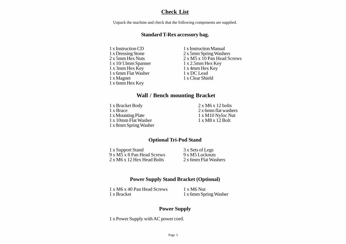
Check List
Unpack the machine and check that the following components are supplied.
Standard T-Rex accessory bag.
1 x Instruction CD 1 x Instruction Manual1 x Dressing Stone 2 x 5mm Spring Washers2 x 5mm Hex Nuts 2 x M5 x 10 Pan Head Screws1 x 10/13mm Spanner 1 x 2.5mm Hex Key1 x 3mm Hex Key 1 x 4mm Hex Key1 x 6mm Flat Washer 1 x DC Lead1 x Magnet 1 x Clear Shield1 x 6mm Hex Key
Wall / Bench mounting Bracket
1 x Bracket Body 2 x M6 x 12 bolts1 x Brace 2 x 6mm flat washers1 x Mounting Plate 1 x M10 Nyloc Nut1 x 10mm Flat Washer 1 x M8 x 12 Bolt1 x 8mm Spring Washer
Optional Tri-Pod Stand
1 x Support Stand 3 x Sets of Legs9 x M5 x 8 Pan Head Screws 9 x M5 Locknuts2 x M6 x 12 Hex Head Bolts 2 x 6mm Flat Washers
Power Supply Stand Bracket (Optional)
1 x M6 x 40 Pan Head Screws 1 x M6 Nut1 x Bracket 1 x 6mm Spring Washer
Power Supply
1 x Power Supply with AC power cord.
Page 6
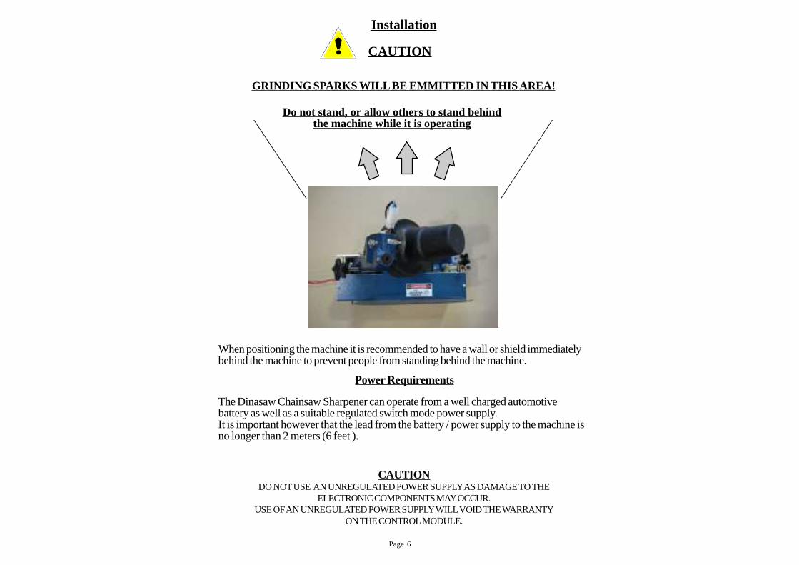
Installation
Do not stand, or allow others to stand behindthe machine while it is operating
When positioning the machine it is recommended to have a wall or shield immediatelybehind the machine to prevent people from standing behind the machine.
The Dinasaw Chainsaw Sharpener can operate from a well charged automotivebattery as well as a suitable regulated switch mode power supply.It is important however that the lead from the battery / power supply to the machine isno longer than 2 meters (6 feet ).
CAUTIONDO NOT USE AN UNREGULATED POWER SUPPLY AS DAMAGE TO THE
ELECTRONIC COMPONENTS MAY OCCUR.USE OF AN UNREGULATED POWER SUPPLY WILL VOID THE WARRANTY
ON THE CONTROL MODULE.
GRINDING SPARKS WILL BE EMMITTED IN THIS AREA!
Power Requirements
CAUTION
Page 7
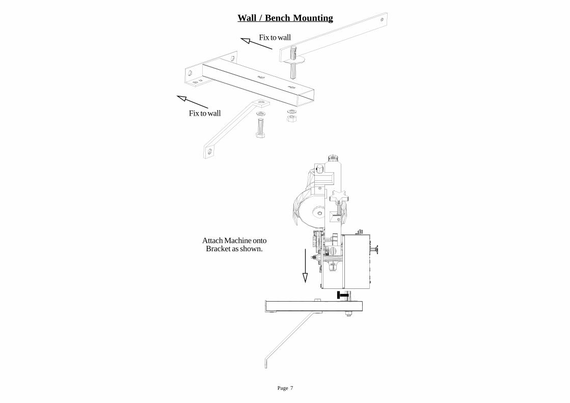
Wall / Bench Mounting
Fix to wall
Fix to wall
Attach Machine ontoBracket as shown.
Page 8
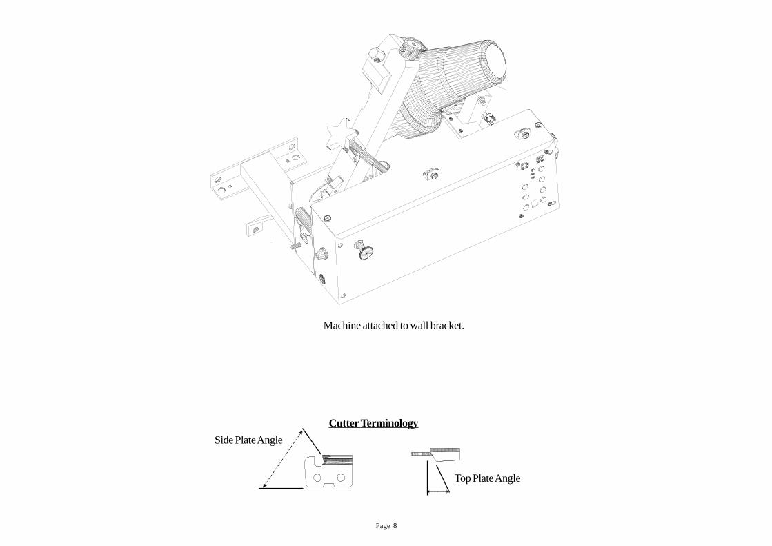
Machine attached to wall bracket.
Side Plate Angle
Cutter Terminology
Top Plate Angle
Page 9
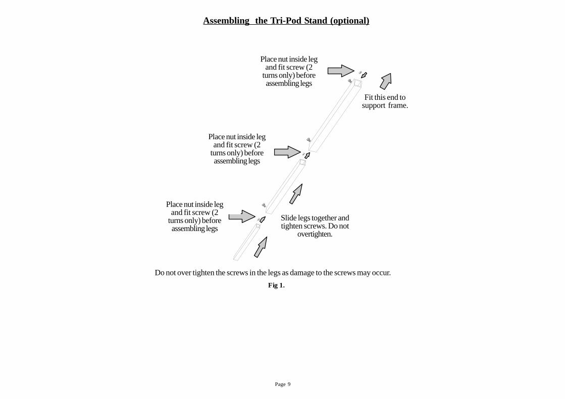
Assembling the Tri-Pod Stand (optional)
Place nut inside leg and fit screw ( 2 turns only ) before assembling legs
Slide legs together and tighten screws. Do not over tighten.
Fit this end onto support frame
Place nut inside leg and fit screw ( 2 turns only ) before assembling legs
Place nut inside leg and fit screw ( 2 turns only ) before assembling legs
Fig 1.
Do not over tighten the screws in the legs as damage to the screws may occur.
Place nut inside legand fit screw (2
turns only) beforeassembling legs
Place nut inside legand fit screw (2
turns only) beforeassembling legs
Place nut inside legand fit screw (2
turns only) beforeassembling legs
Slide legs together andtighten screws. Do not
overtighten.
Fit this end tosupport frame.
Page 10
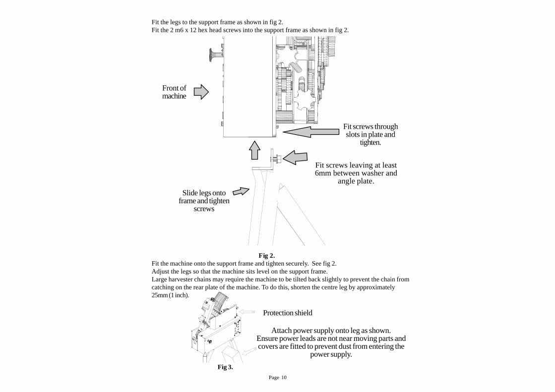
Fig 3.
Protection shield
Attach power supply onto leg as shown.Ensure power leads are not near moving parts andcovers are fitted to prevent dust from entering the
power supply.
Fit the legs to the support frame as shown in fig 2.Fit the 2 m6 x 12 hex head screws into the support frame as shown in fig 2.
Fit screws through slots in plate and tighten.
Fit screws leaving at least 6mm between washer and angle plate
Slide legs onto frame and tighten screws.
Fig 2.
Front of machine
Fit the machine onto the support frame and tighten securely. See fig 2.Adjust the legs so that the machine sits level on the support frame.Large harvester chains may require the machine to be tilted back slightly to prevent the chain fromcatching on the rear plate of the machine. To do this, shorten the centre leg by approximately25mm (1 inch).
Front ofmachine
Fit screws leaving at least6mm between washer and
angle plate.
Slide legs ontoframe and tighten
screws
Fit screws throughslots in plate and
tighten.
Page 11
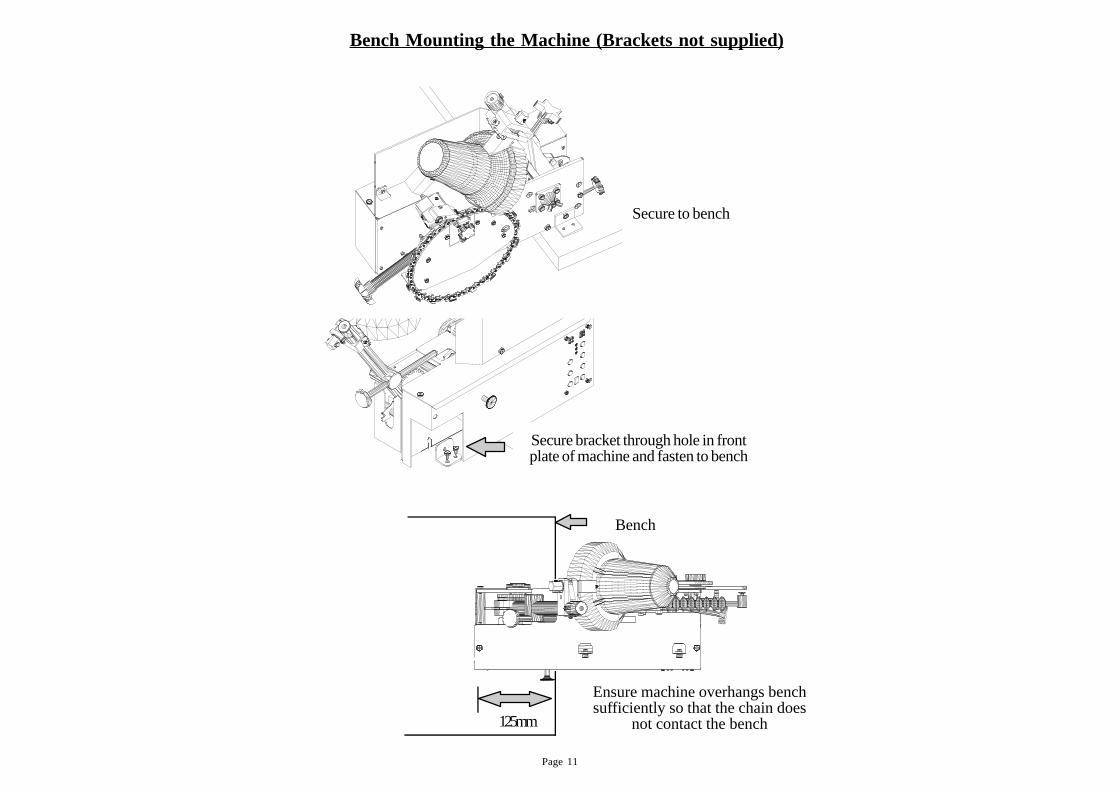
Bench Mounting the Machine (Brackets not supplied)
125mm
BENCH
Ensure machine overhangs bench suffi-ciently so that the chain does not contact the bench.
Secure bracket through slot in front plate of machine and fasten to bench.
Secure bracket through hole in frontplate of machine and fasten to bench
Bench
Ensure machine overhangs benchsufficiently so that the chain does
not contact the bench125mm
Secure to bench
Page 12
Overview of Operation
The T-Rex uses cams to operate the feed, clamp and grinding head. The “Grind Cam”raises and lowers the grinding head while the “Feed Cam” both indexes and clamps thecutters.
CAUTION:
Excessive clamping pressure will damage the machine
The T-REX model has four modes of operation.“OFF” - Sharpens left and right hand cutters without detection“AUTO” - Uses cutter sensor to detect and grind two cutters in a row.“MAGNET” - Uses a magnet to detect and grind two cutters in a row.“SCRATCHER” - Allows thesharpening of scratcher chain.(Requires options).
The machine uses four sensors to operate automatically.1. The cutter sensor “looks” at each cutter and determines what hand it is.2. The proximity switch senses a magnet placed on a cutter to correct the grind-
ing sequence for out of sequence cutters. It also serves as a counter to auto-matically shut off the machine.
3. Two other sensors are located inside the machine. One in the feed motor tocount motor revolutions and another behind the idler gear which checks thebevel angle of the grinding head.
Adjustments
There are four main adjustments which need to be made when changing betweendifferent size chains. (see previous page)1. Limiting the feed stroke.2. Setting the feed pawl height.3. Centering the grinding head. 4. Chain Clamp
Limitations
1. The T-Rex model cannot automatically sharpen chains with three or morecutters in a row on the same side of the chain. Two is the maximium.
3. Chains with three or more tie links in one section of the chain must be stoppedat this point with the magnet, as the feed stroke will not cope with more thantwo tie links.
4. Chains with double tie links cannot be sharpened using “AUTO” mode as thesensor will not ‘see’ the cutter after the double link. Only use “MAGNET” or“OFF” mode on these chains.
Page 13
Plug the machine in and turn the emergency stop switch on to power up the machine.
Power indicator light:• Indicates that power is on.
Function indicator light:• When in “Run Mode” light is on.• When magnet is detected light will go out momentarily.
Detection mode indicator:• Indicates which mode machine is in.• “OFF” - No detection. Machine grinds sequentially.• “AUT O” - Automatically detects double cutters (left or right).• “MAGNET” - Corrects only after chain magnet passes proximity switch.
Stop / Reset:• Stops the machine
Star t:• Starts the feed mechanism.
Grinder:• Turns the grinder motor on - press again stops motor.
Inch Fwd:• “Inches” machine forward when not in run mode.
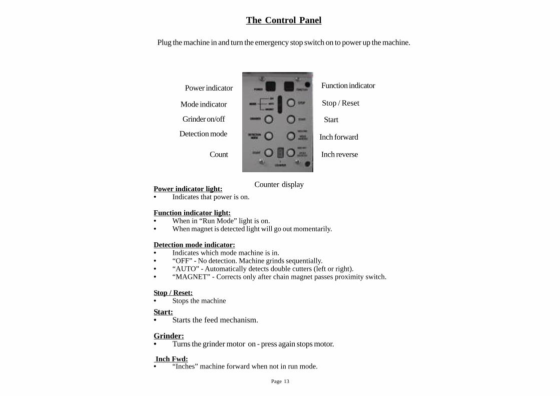
Power indicator
Detection mode
Grinder on/off
Mode indicator
Count
Function indicator
Stop / Reset
Start
Inch forward
Inch reverse
Counter display
The Control Panel
Page 14
Inch Rev:• “Inches” machine in reverse when not in run mode.
Detection Mode:• Changes between the three detection modes and is shown by the Mode Indicator
lights.
Counter:• Sets number of times chain circuits (maximum of 9)• Counter is triggered by placing the magnet on chain (Low down on sideplate,on or
between the rivets of a cutter).
Counter Display:• Indicates number of circuits chain will do, referenced by the chain magnet.
Holding Count and pressing Inch Fwd.• Positions the machine for adjusting the top plate angle of LEFT hand cutters.• Display will show a symbol.
Holding Count and pressing Inch Rev.:• Positions the machine for adjusting the top plate angle of RIGHT hand cutters.• Display will show a symbol.
Page 15
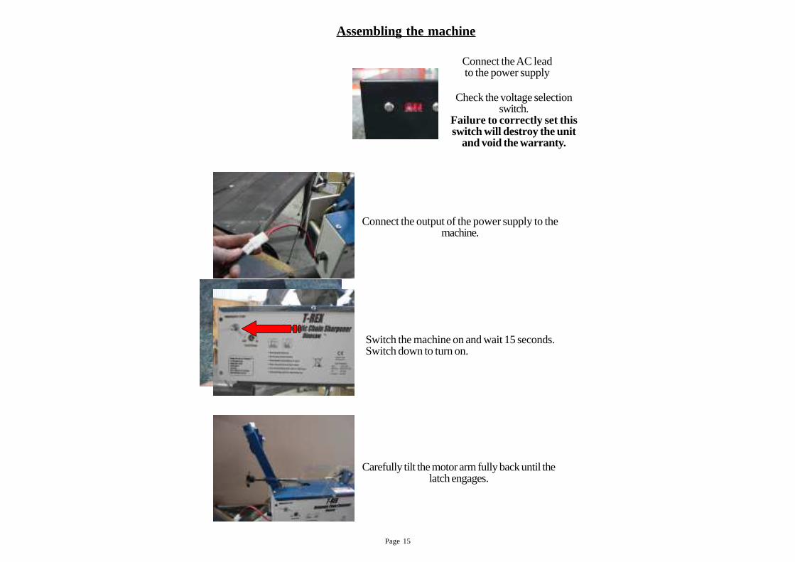
Assembling the machine
Switch the machine on and wait 15 seconds.Switch down to turn on.
Connect the AC leadto the power supply
Carefully tilt the motor arm fully back until thelatch engages.
Connect the output of the power supply to themachine.
Check the voltage selectionswitch.
Failure to correctly set thisswitch will destroy the unit
and void the warranty.
Page 16
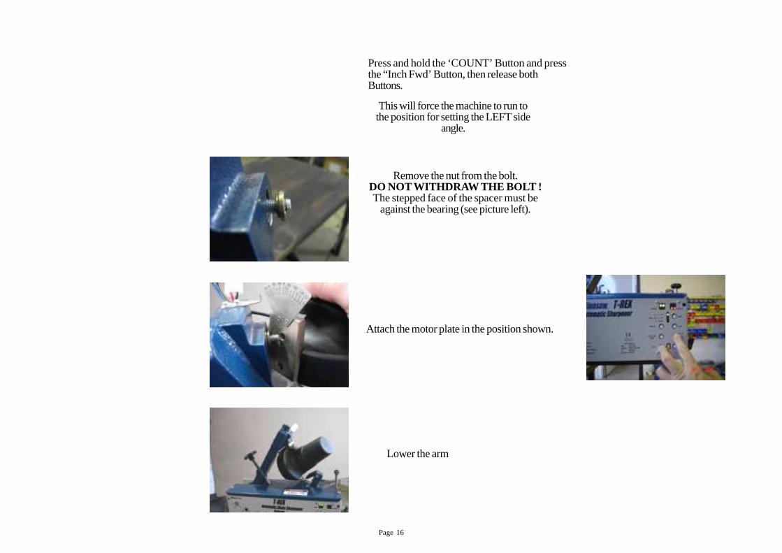
Press and hold the ‘COUNT’ Button and pressthe “Inch Fwd’ Button, then release bothButtons.
Remove the nut from the bolt.DO NOT WITHDRA W THE BOLT !The stepped face of the spacer must be
against the bearing (see picture left).
Attach the motor plate in the position shown.
Lower the arm
This will force the machine to run tothe position for setting the LEFT side
angle.
Page 17
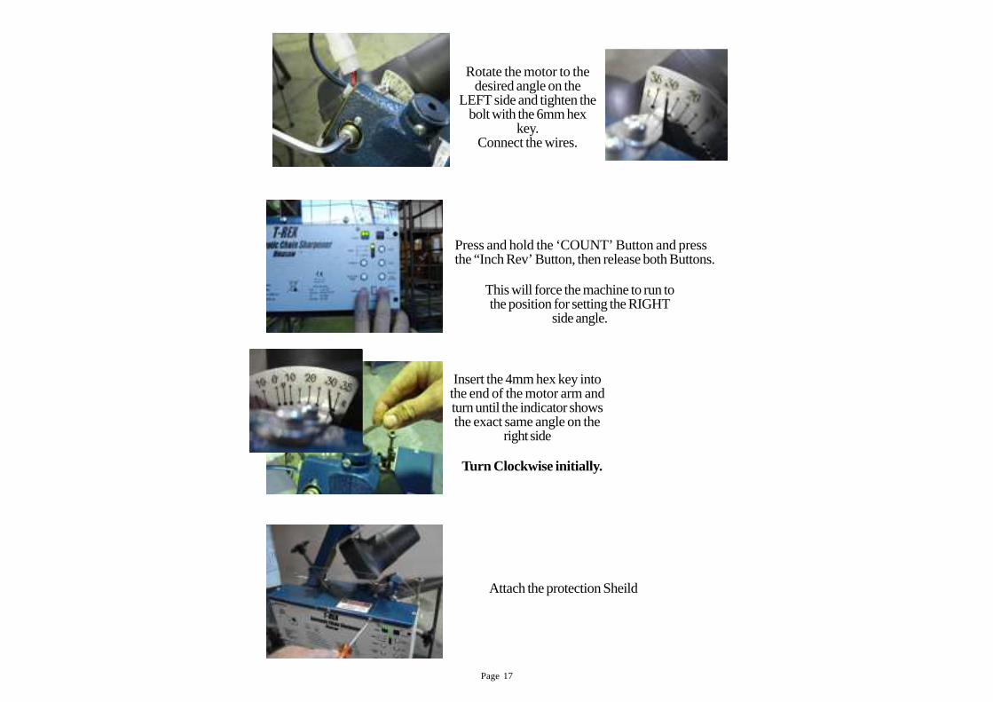
Press and hold the ‘COUNT’ Button and pressthe “Inch Rev’ Button, then release both Buttons.
Insert the 4mm hex key intothe end of the motor arm andturn until the indicator showsthe exact same angle on the
right side
Attach the protection Sheild
Rotate the motor to thedesired angle on the
LEFT side and tighten thebolt with the 6mm hex
key.Connect the wires.
This will force the machine to run tothe position for setting the RIGHT
side angle.
Turn Clockwise initially.
Page 18
Adjustments
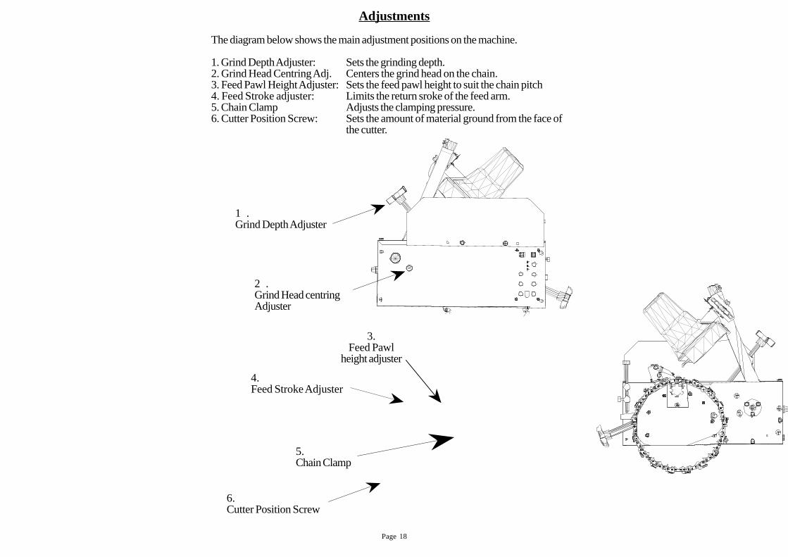
The diagram below shows the main adjustment positions on the machine.
1. Grind Depth Adjuster: Sets the grinding depth.2. Grind Head Centring Adj. Centers the grind head on the chain.3. Feed Pawl Height Adjuster: Sets the feed pawl height to suit the chain pitch4. Feed Stroke adjuster: Limits the return sroke of the feed arm.5. Chain Clamp Adjusts the clamping pressure.6. Cutter Position Screw: Sets the amount of material ground from the face of
the cutter.
6.Cutter Position Screw
3.Feed Pawl
height adjuster
4.Feed Stroke Adjuster
5.Chain Clamp
1 .Grind Depth Adjuster
2 .Grind Head centringAdjuster
Page 19
Fit self tapping screws and attach Wheel cover here.
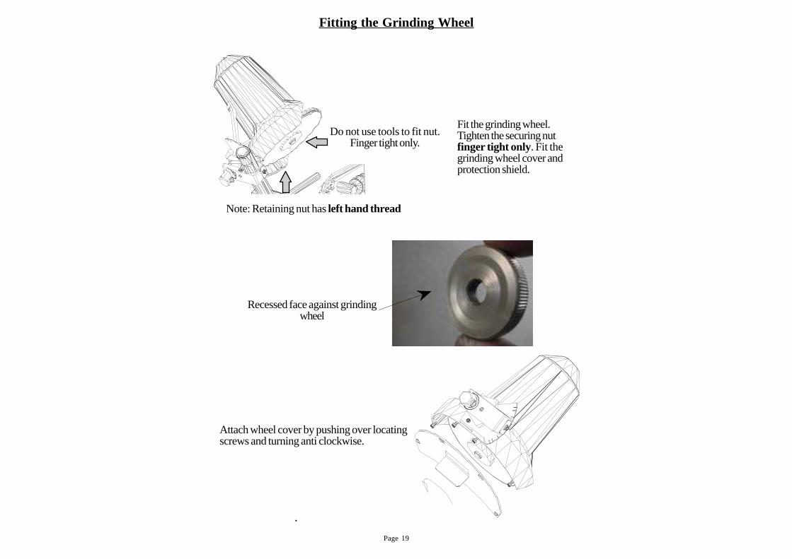
Do not use tools to fit retaining nut. Finger tight only.
.
Attach wheel cover by pushing over locatingscrews and turning anti clockwise.
Fitting the Grinding Wheel
Do not use tools to fit nut.Finger tight only.
Fit the grinding wheel.Tighten the securing nutfinger tight only. Fit thegrinding wheel cover andprotection shield.
Note: Retaining nut has left hand thread
Recessed face against grindingwheel

Page 20
Dressing and Truing the Grinding wheel
CAUTION: Grinding wheels may shatter causing injury.
Grinding dust has been associated with respiratory disease.Preferably use ABN / CBN wheels and wear a suitable dust mask
Resin bond Grinding WheelsFit and secure the appropriate grinding wheel (note left hand thread)Before starting the grinding wheel check that it is rated at 6500 RPM or more and isnot cracked or damaged.Raise the grinding head fully so that the catch holds the head back.Do not lift the grinding head by the motor. Always lift the head by the handle on thedepth adjusting screw.When satisfied the wheel is okay, make sure there are no bystanders near the machineand, standing behind the grinding wheel shroud press the grinder button.
Raise and lowermotor arm by the
Motor armlatch
It is prudent not to trust the integrety of a newly fitted, bonded grindingwheel - run for at least one minute before dressing the wheel to the requiredshape.
CAUTION
Page 21
CAUTION
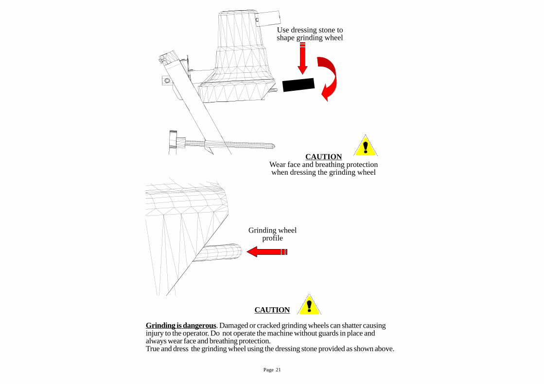
Grinding is dangerous. Damaged or cracked grinding wheels can shatter causinginjury to the operator. Do not operate the machine without guards in place andalways wear face and breathing protection.True and dress the grinding wheel using the dressing stone provided as shown above.
Use dressing stone toshape grinding wheel
CAUTIONWear face and breathing protectionwhen dressing the grinding wheel
Grinding wheelprofile
Page 22
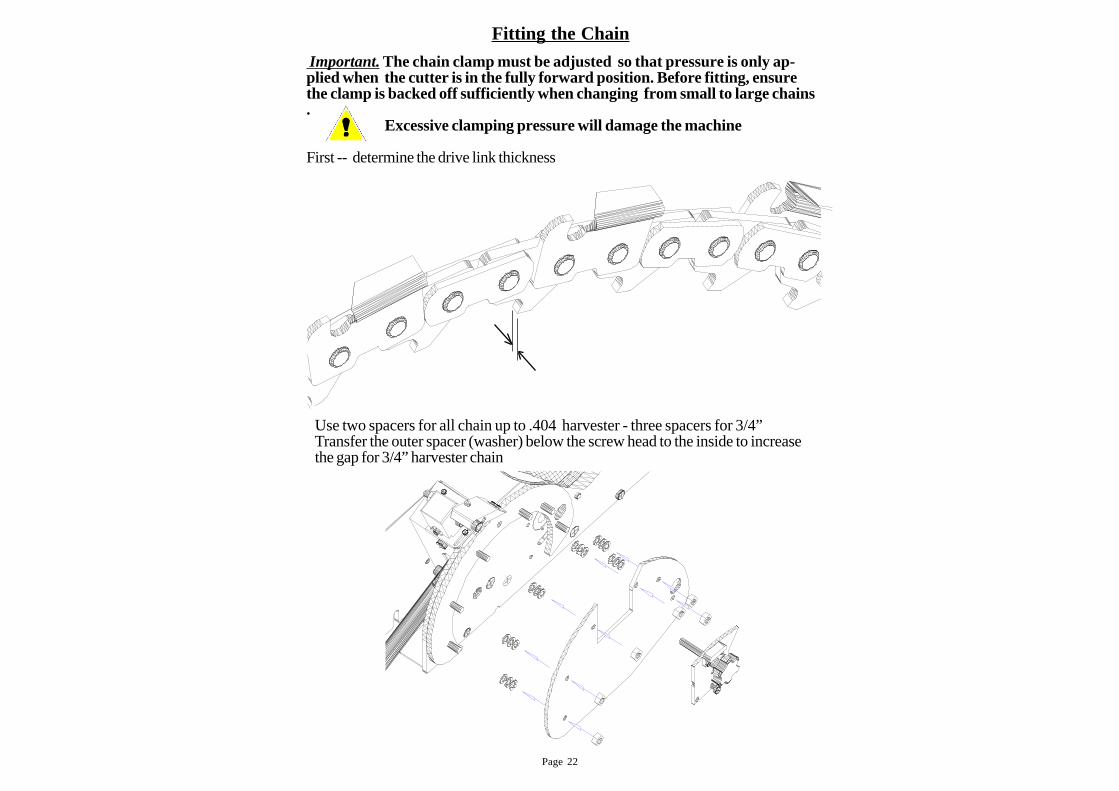
3 x Spacers for 3/4” Harvester2 x Spacers for smaller chains
Fitting the Chain
Important. The chain clamp must be adjusted so that pressure is only ap-plied when the cutter is in the fully forward position. Before fitting, ensurethe clamp is backed off sufficiently when changing from small to large chains.
Excessive clamping pressure will damage the machine
First -- determine the drive link thickness
Use two spacers for all chain up to .404 harvester - three spacers for 3/4”Transfer the outer spacer (washer) below the screw head to the inside to increasethe gap for 3/4” harvester chain
Page 23
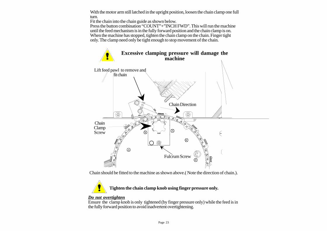
Tighten the chain clamp knob using finger pressure only.
Do not overtightenEnsure the clamp knob is only tightened (by finger pressure only) while the feed is inthe fully forward position to avoid inadvertent overtightening.
With the motor arm still latched in the upright position, loosen the chain clamp one fullturn.Fit the chain into the chain guide as shown below.Press the button combination “COUNT”+”INCH FWD”. This will run the machineuntil the feed mechanism is in the fully forward position and the chain clamp is on.When the machine has stopped, tighten the chain clamp on the chain. Finger tightonly. The clamp need only be tight enough to stop movement of the chain.
Excessive clamping pressure will damage themachine
Chain should be fitted to the machine as shown above.( Note the direction of chain.).
Lift feed pawl to remove andfit chain
Chain Direction
Fulcrum Screw
ChainClampScrew
Page 24
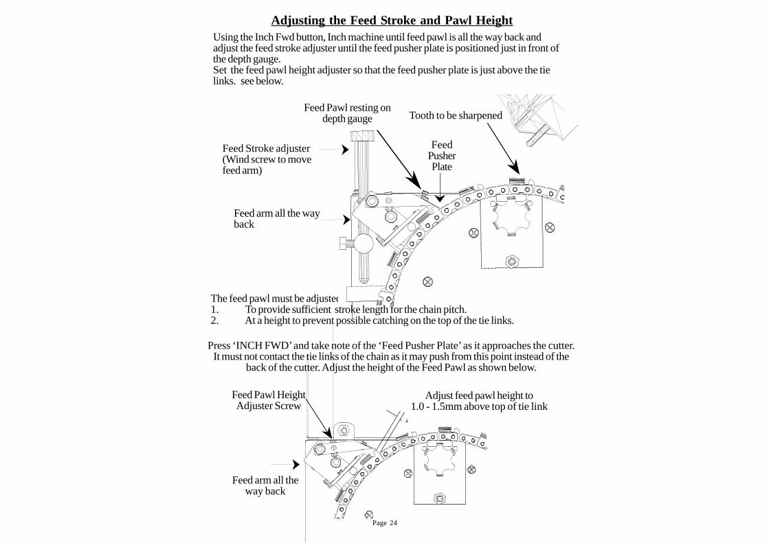
Adjust feed pawl height to1.0 - 1.5mm above top of tie link
Feed Pawl HeightAdjuster Screw
Feed arm all theway back
The feed pawl must be adjusted:1. To provide sufficient stroke length for the chain pitch.2. At a height to prevent possible catching on the top of the tie links.
Adjusting the Feed Str oke and Pawl HeightUsing the Inch Fwd button, Inch machine until feed pawl is all the way back andadjust the feed stroke adjuster until the feed pusher plate is positioned just in front ofthe depth gauge.Set the feed pawl height adjuster so that the feed pusher plate is just above the tielinks. see below.
Tooth to be sharpened
Feed Stroke adjuster(Wind screw to movefeed arm)
Feed arm all the wayback
FeedPusherPlate
Feed Pawl resting ondepth gauge
Press ‘INCH FWD’ and take note of the ‘Feed Pusher Plate’ as it approaches the cutter.It must not contact the tie links of the chain as it may push from this point instead of the
back of the cutter. Adjust the height of the Feed Pawl as shown below.
Page 25
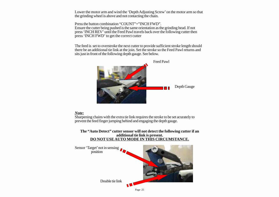
The “Auto Detect” cutter sensor will not detect the following cutter if anadditional tie link is present.
DO NOT USE AUTO MODE IN THIS CIRCUMST ANCE.
Lower the motor arm and wind the ‘Depth Adjusting Screw’ on the motor arm so thatthe grinding wheel is above and not contacting the chain.
Press the button combination “COUNT”+”INCH FWD”.Ensure the cutter being pushed is the same orientation as the grinding head. If notpress ‘INCH REV’ until the Feed Pawl travels back over the following cutter thenpress ‘INCH FWD’ to get the correct cutter
The feed is set to overstroke the next cutter to provide sufficient stroke length shouldthere be an additional tie link at the join. Set the stroke so the Feed Pawl returns andsits just in front of the following depth gauge. See below.
Note:Sharpening chains with the extra tie link requires the stroke to be set acurately toprevent the feed finger jumping behind and engaging the depth gauge.
Feed Pawl
Depth Gauge
Sensor ‘Target’ not in sensingposition
Double tie link

Page 26
‘AUTO’ Mode Setup
This mode uses sensors to determine if there are two cutters ina ro on the same side of the chain.
This mode uses a sensor to “look”at the cutter and determine what hand it is. If thereare two cutters on the same side of the chain, the grinding head will automaticallyorientate itself and grind both cutters.** This mode requires careful and accurate adjustment of the “Cutter Sensor”. Seefollowing page.
Caution: Check chain for bent or broken cutters before using AUTO mode.
DO NOT USE ‘AUTO’ MODE ON CHAINS WITH DOUBLE TIE LINKS.
Fit the chain into the chain guide making sure that the hand of the cutter is the same asthe grinding head orientation. If it is not, press ‘INCH REV’ then ‘INCH FWD’ tosynchronise the grinding head and the cutter.
Press and hold the “COUNT” then press “INCH REV” then release both buttons.The display will show a symbol and the machine will position itself with the headangled away from the operator (right).
The following series of pictures shows the correct setting of the tooth sensor.
‘OFF’ Mode Setup
This mode assumes the chain has no double cutters and no extra tie links.
1. Press ‘INCH FWD’ and ensure the cutter and the grinding head are angled thesame way. If not, press ‘INCH REV’ until the Feed Pawl travels back overthe following cutter then press ‘INCH FWD’ to get the correct cutter
2. Select ‘OFF’ mode3. Attach magnet to first rivet on any cutter4. Select number of chain rotations by pressing ‘COUNT’5. Press ‘START’ then ‘GRINDER’
Page 27
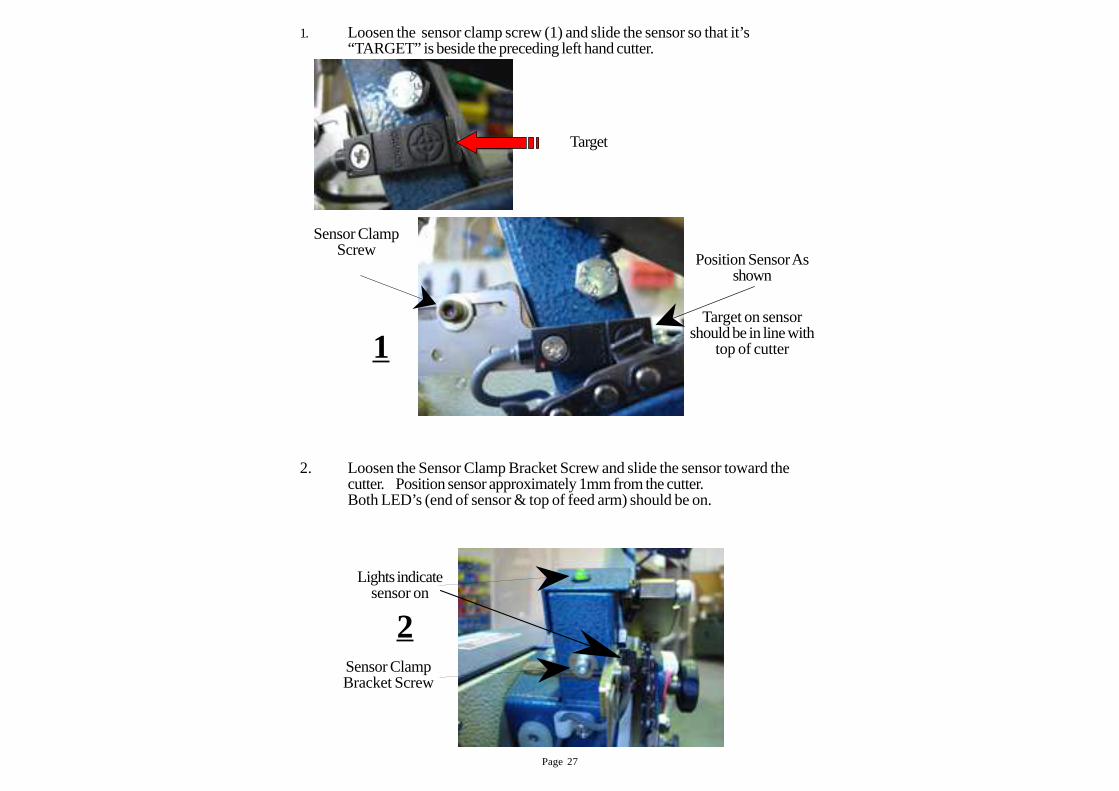
2. Loosen the Sensor Clamp Bracket Screw and slide the sensor toward thecutter. Position sensor approximately 1mm from the cutter.Both LED’s (end of sensor & top of feed arm) should be on.
1. Loosen the sensor clamp screw (1) and slide the sensor so that it’s“TARGET” is beside the preceding left hand cutter.
Lights indicate
sensor on
Sensor ClampBracket Screw
2
Position Sensor Asshown
Sensor ClampScrew
Target on sensorshould be in line with
top of cutter1
Target
Page 28
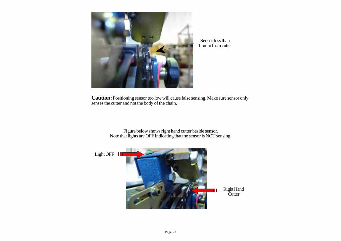
Caution: Positioning sensor too low will cause false sensing. Make sure sensor onlysenses the cutter and not the body of the chain.
Figure below shows right hand cutter beside sensor.Note that lights are OFF indicating that the sensor is NOT sensing.
Right HandCutter
Light OFF
Sensor less than1.5mm from cutter
Page 29
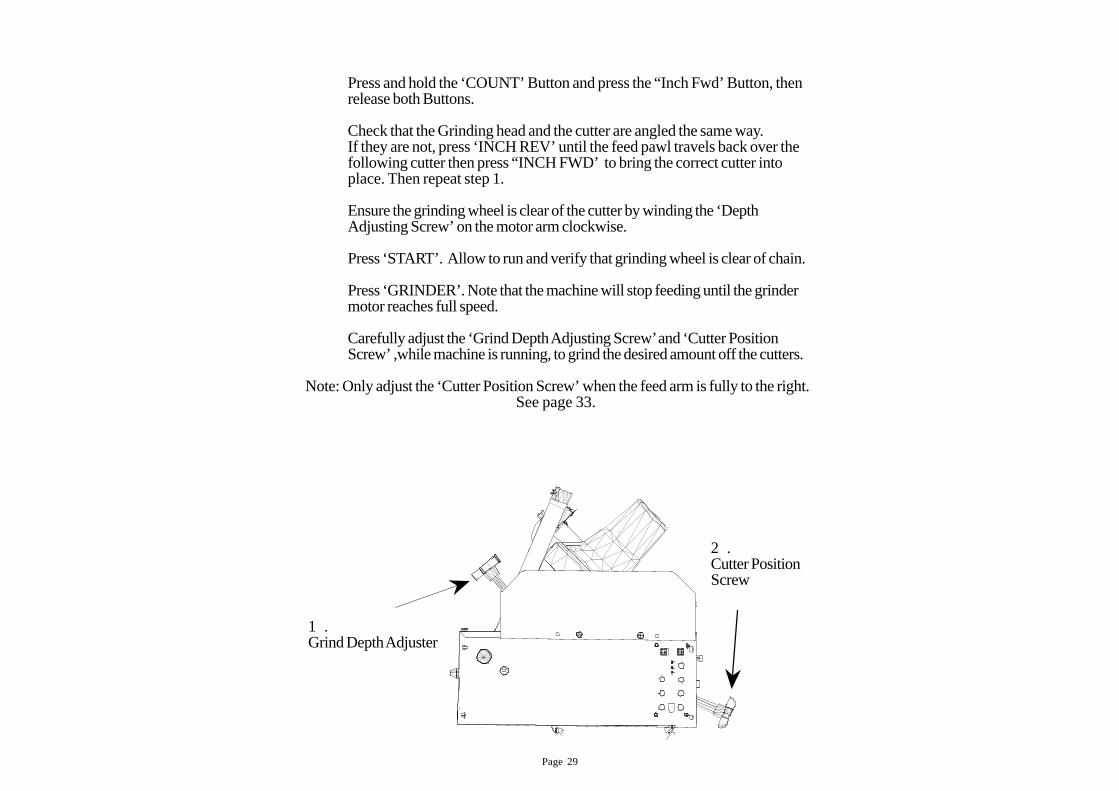
Press and hold the ‘COUNT’ Button and press the “Inch Fwd’ Button, thenrelease both Buttons.
Check that the Grinding head and the cutter are angled the same way.If they are not, press ‘INCH REV’ until the feed pawl travels back over thefollowing cutter then press “INCH FWD’ to bring the correct cutter intoplace. Then repeat step 1.
Ensure the grinding wheel is clear of the cutter by winding the ‘DepthAdjusting Screw’ on the motor arm clockwise.
Press ‘START’. Allow to run and verify that grinding wheel is clear of chain.
Press ‘GRINDER’. Note that the machine will stop feeding until the grindermotor reaches full speed.
Carefully adjust the ‘Grind Depth Adjusting Screw’ and ‘Cutter PositionScrew’ ,while machine is running, to grind the desired amount off the cutters.
Note: Only adjust the ‘Cutter Position Screw’ when the feed arm is fully to the right.See page 33.
1 .Grind Depth Adjuster
2 .Cutter PositionScrew
Page 30
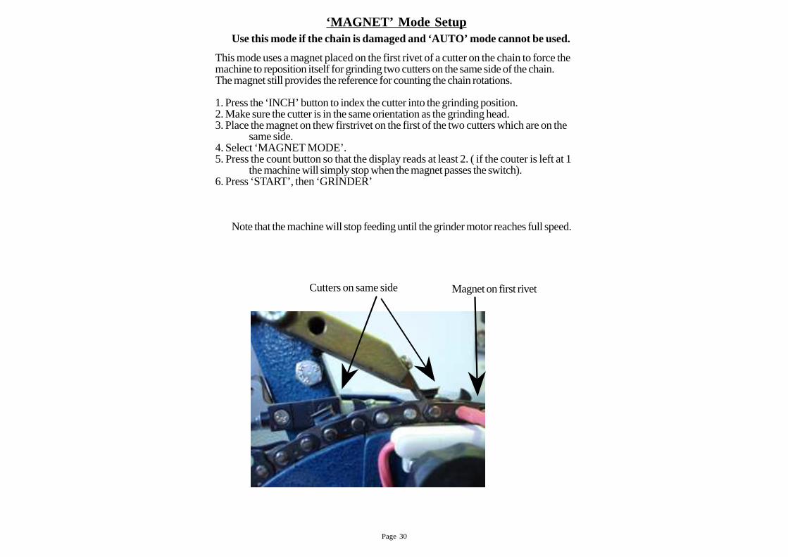
This mode uses a magnet placed on the first rivet of a cutter on the chain to force themachine to reposition itself for grinding two cutters on the same side of the chain.The magnet still provides the reference for counting the chain rotations.
1. Press the ‘INCH’ button to index the cutter into the grinding position.2. Make sure the cutter is in the same orientation as the grinding head.3. Place the magnet on thew firstrivet on the first of the two cutters which are on the
same side.4. Select ‘MAGNET MODE’.5. Press the count button so that the display reads at least 2. ( if the couter is left at 1
the machine will simply stop when the magnet passes the switch).6. Press ‘START’, then ‘GRINDER’
‘MAGNET’ Mode Setup
Note that the machine will stop feeding until the grinder motor reaches full speed.
Cutters on same side Magnet on first rivet
Use this mode if the chain is damaged and ‘AUTO’ mode cannot be used.
Page 31
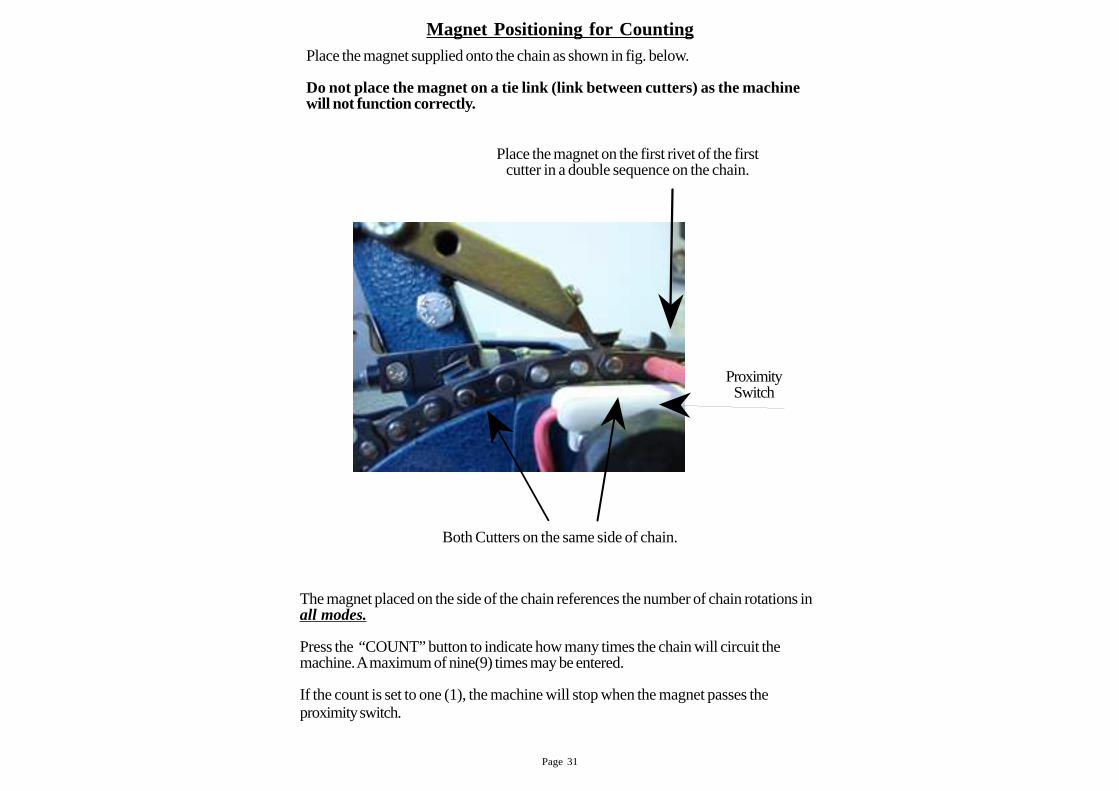
Place the magnet supplied onto the chain as shown in fig. below.
Do not place the magnet on a tie link (link between cutters) as the machinewill not function corr ectly.
Magnet Positioning for Counting
The magnet placed on the side of the chain references the number of chain rotations inall modes.
Press the “COUNT” button to indicate how many times the chain will circuit themachine. A maximum of nine(9) times may be entered.
If the count is set to one (1), the machine will stop when the magnet passes theproximity switch.
Place the magnet on the first rivet of the firstcutter in a double sequence on the chain.
Both Cutters on the same side of chain.
ProximitySwitch
Page 32
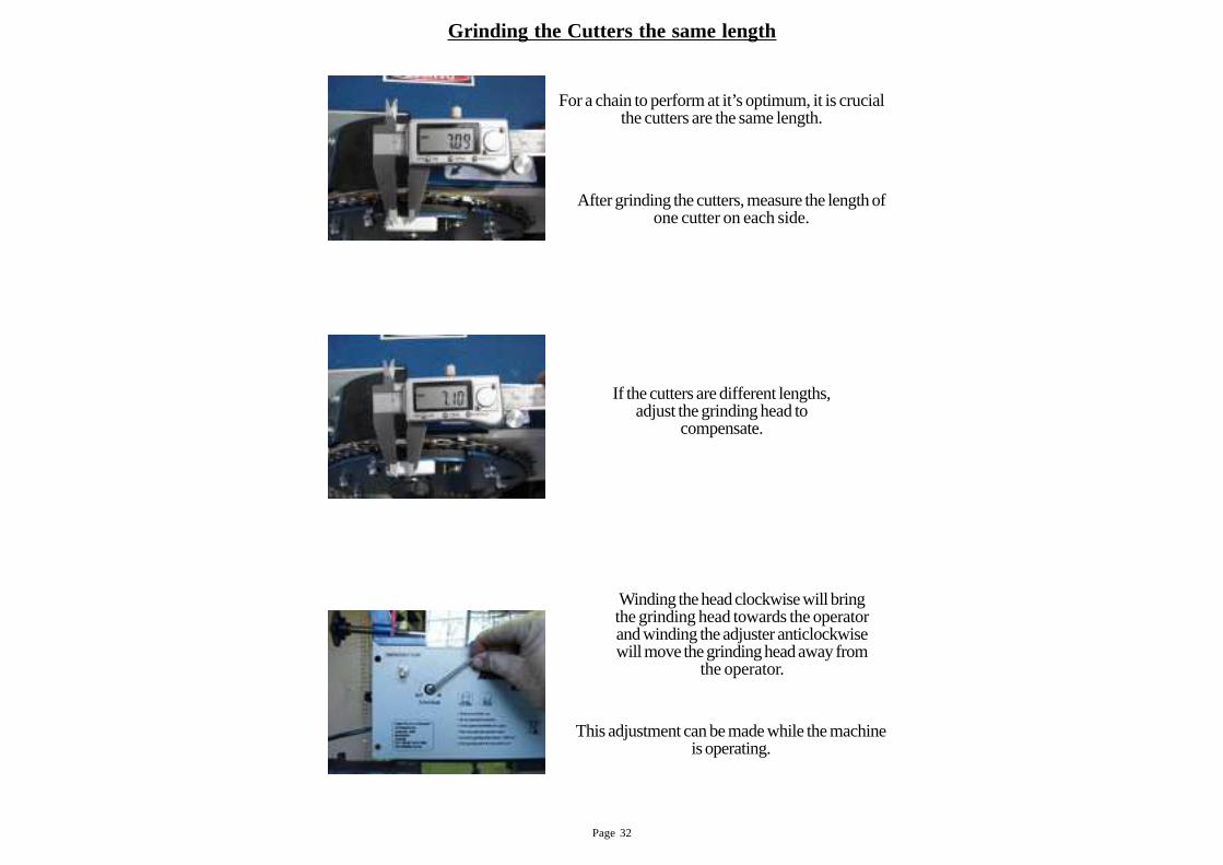
Grinding the Cutters the same length
After grinding the cutters, measure the length ofone cutter on each side.
If the cutters are different lengths,adjust the grinding head to
compensate.
Winding the head clockwise will bringthe grinding head towards the operatorand winding the adjuster anticlockwisewill move the grinding head away from
the operator.
This adjustment can be made while the machineis operating.
For a chain to perform at it’s optimum, it is crucialthe cutters are the same length.
Page 33
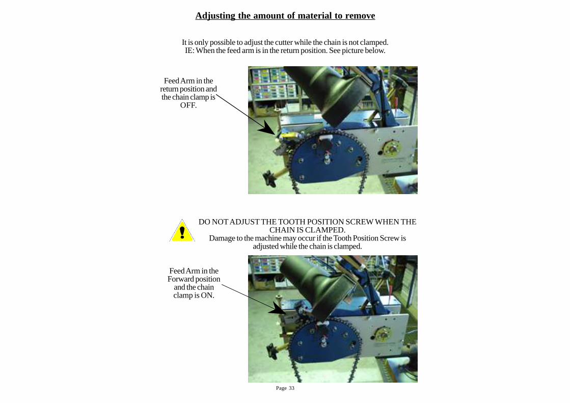
Adjusting the amount of material to remove
It is only possible to adjust the cutter while the chain is not clamped.IE: When the feed arm is in the return position. See picture below.
DO NOT ADJUST THE TOOTH POSITION SCREW WHEN THECHAIN IS CLAMPED.
Damage to the machine may occur if the Tooth Position Screw isadjusted while the chain is clamped.
Feed Arm in the
return position andthe chain clamp is
OFF.
Feed Arm in theForward position
and the chainclamp is ON.

Page 34
The following section deals with altering the settingsfrom standard
Page 35
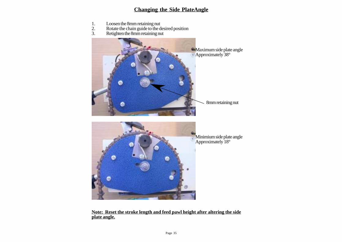
Changing the Side PlateAngle
1. Loosen the 8mm retaining nut2. Rotate the chain guide to the desired position3. Retighten the 8mm retaining nut
8mm retaining nut
Maximum side plate angleApproximately 38°
Minimium side plate angleApproximately 18°
Note: Reset the stroke length and feed pawl height after altering the sideplate angle.
Page 36
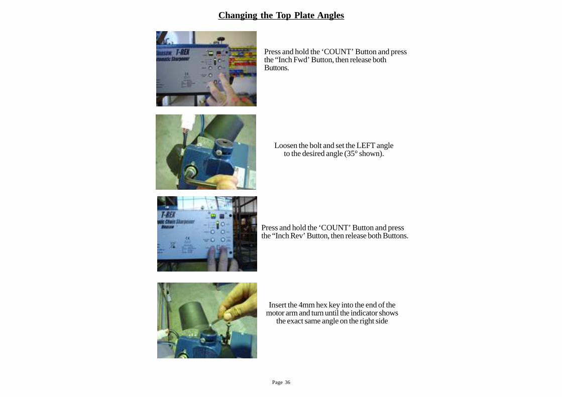
Changing the Top Plate Angles
Loosen the bolt and set the LEFT angleto the desired angle (35° shown).
Insert the 4mm hex key into the end of themotor arm and turn until the indicator shows
the exact same angle on the right side
Press and hold the ‘COUNT’ Button and pressthe “Inch Fwd’ Button, then release bothButtons.
Press and hold the ‘COUNT’ Button and pressthe “Inch Rev’ Button, then release both Buttons.
Page 37
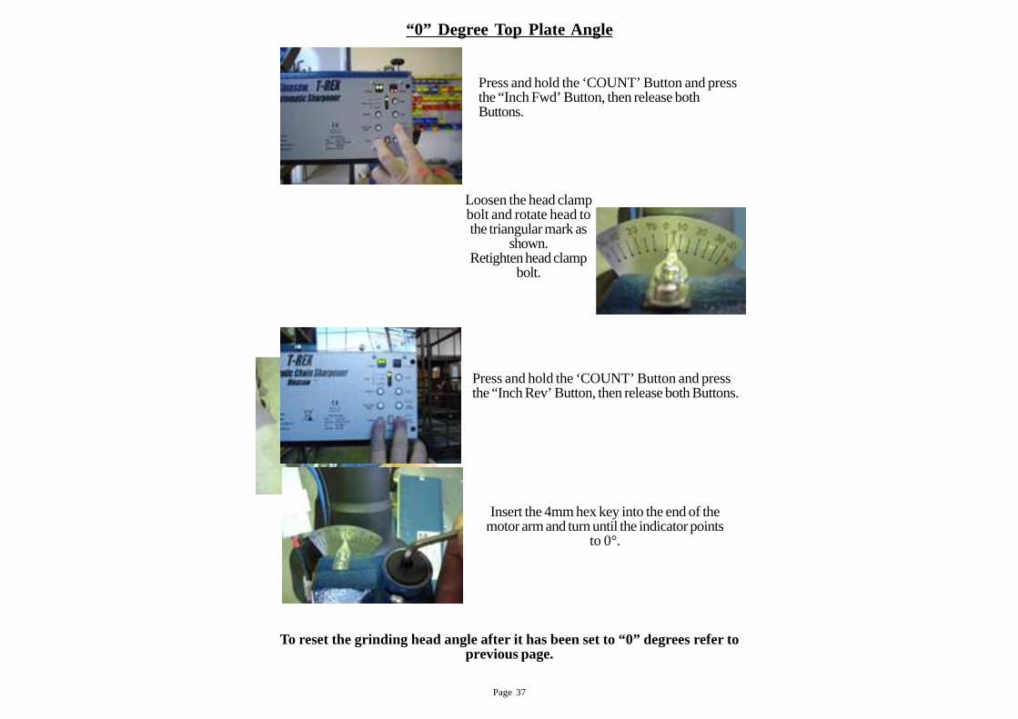
To reset the grinding head angle after it has been set to “0” degrees refer toprevious page.
“0” Degr ee Top Plate Angle
Press and hold the ‘COUNT’ Button and pressthe “Inch Fwd’ Button, then release bothButtons.
Loosen the head clampbolt and rotate head tothe triangular mark as
shown.Retighten head clamp
bolt.
Press and hold the ‘COUNT’ Button and pressthe “Inch Rev’ Button, then release both Buttons.
Insert the 4mm hex key into the end of themotor arm and turn until the indicator points
to 0°.
Page 38
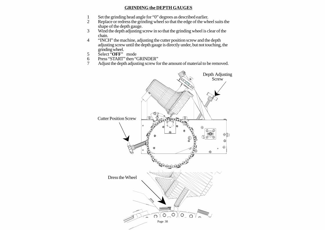
GRINDING the DEPTH GAUGES
1 Set the grinding head angle for “0” degrees as described earlier.2 Replace or redress the grinding wheel so that the edge of the wheel suits the
shape of the depth gauge.3 Wind the depth adjusting screw in so that the grinding wheel is clear of the
chain.4 “INCH” the machine, adjusting the cutter position screw and the depth
adjusting screw until the depth gauge is directly under, but not touching, thegrinding wheel.
5 Select “OFF” mode6 Press “START” then “GRINDER”7 Adjust the depth adjusting screw for the amount of material to be removed.
Cutter Position Screw
Depth AdjustingScrew
Dress the Wheel
Page 39
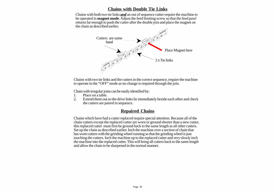
Chains with Double Tie LinksChains with both two tie links and an out of sequence cutter require the machine tobe operated in magnet mode. Adjust the feed limiting screw so that the feed pawlreturns far enough to push the cutter after the double join and place the magnet onthe chain as described earlier.
2 x Tie links
Cutters are same
hand
Repaired Chains
Chains which have had a cutter replaced require special attention. Because all of thechain cutters except the replaced cutter are worn or ground shorter than a new cutter,this replaced cutter must first be ground back to the same length as all other cutters.Set up the chain as described earlier. Inch the machine over a section of chain thathas worn cutters with the grinding wheel running so that the grinding wheel is justtouching the cutters. Inch the machine up to the replaced cutter and very slowly inchthe machine into the replaced cutter. This will bring all cutters back to the same lengthand allow the chain to be sharpened in the normal manner.
Place Magnet here
Chains with two tie links and the cutters in the correct sequence, require the machineto operate in the “OFF” mode as no change is required through the join.
Chain with irregular joins can be easily identified by:1. Place on a table.2. Extend them out so the drive links lie immediately beside each other and check
the cutters are paired in sequence.
Page 40
Double joiner link
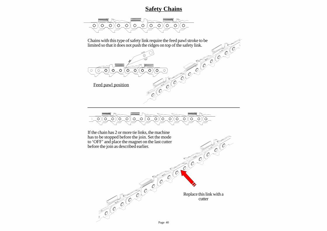
Safety Chains
If the chain has 2 or more tie links, the machinehas to be stopped before the join. Set the modeto ‘OFF’ and place the magnet on the last cutterbefore the join as described earlier.
Chains with this type of safety link require the feed pawl stroke to belimited so that it does not push the ridges on top of the safety link.
Feed pawl position
Replace this link with a
cutter
Page 41
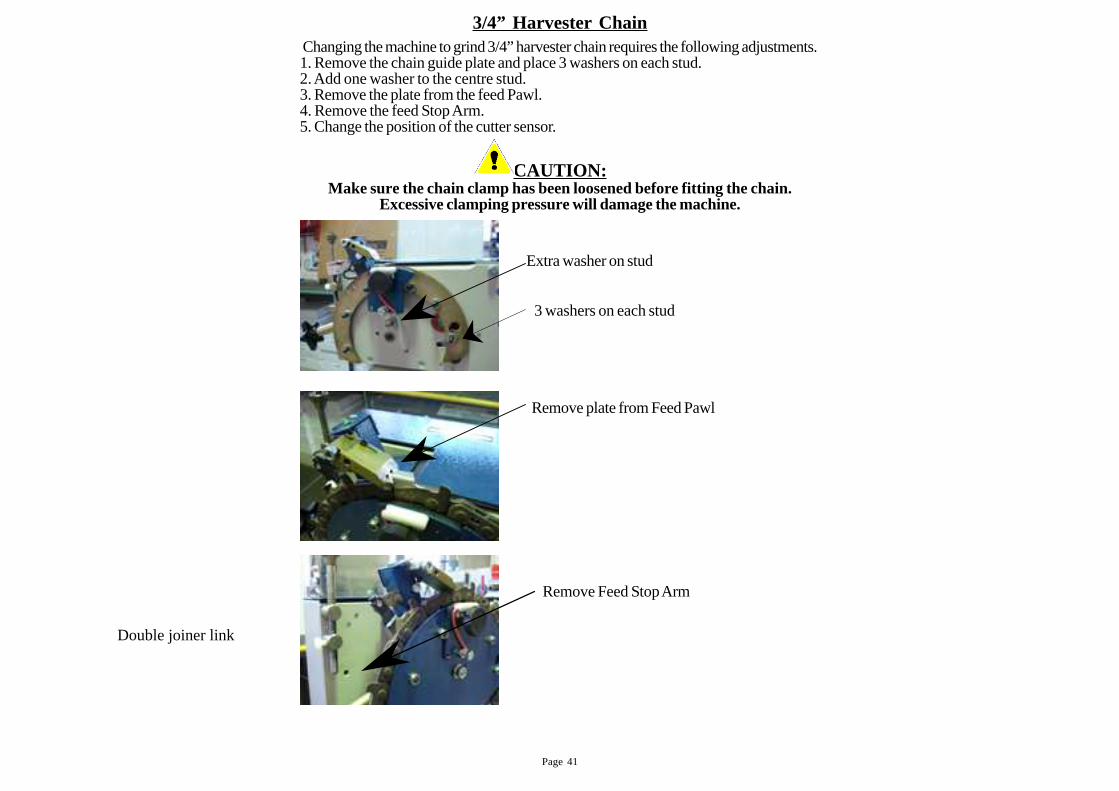
3/4” Harvester Chain
3 washers on each stud
Extra washer on stud
Remove plate from Feed Pawl
Remove Feed Stop Arm
Changing the machine to grind 3/4” harvester chain requires the following adjustments.1. Remove the chain guide plate and place 3 washers on each stud.2. Add one washer to the centre stud.3. Remove the plate from the feed Pawl.4. Remove the feed Stop Arm.5. Change the position of the cutter sensor.
CAUTION:Make sure the chain clamp has been loosened before fitting the chain.
Excessive clamping pressure will damage the machine.
Double joiner link
Page 42
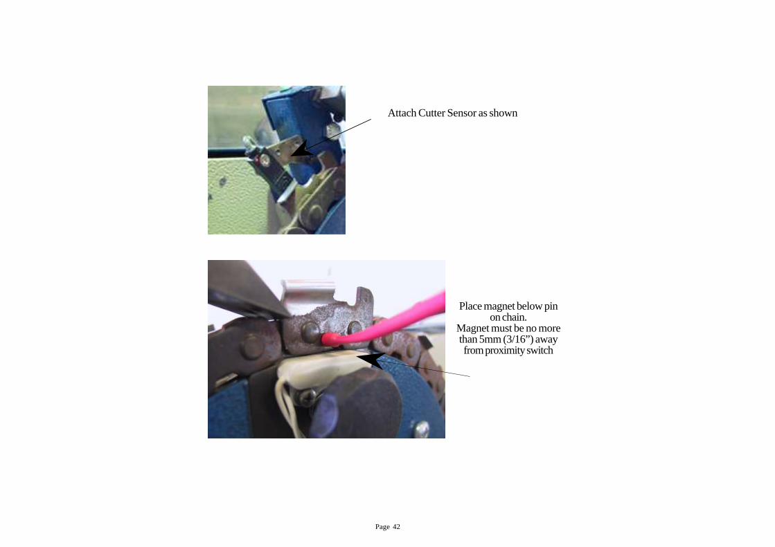
Place magnet below pinon chain.
Magnet must be no morethan 5mm (3/16”) awayfrom proximity switch
Attach Cutter Sensor as shown
Page 43
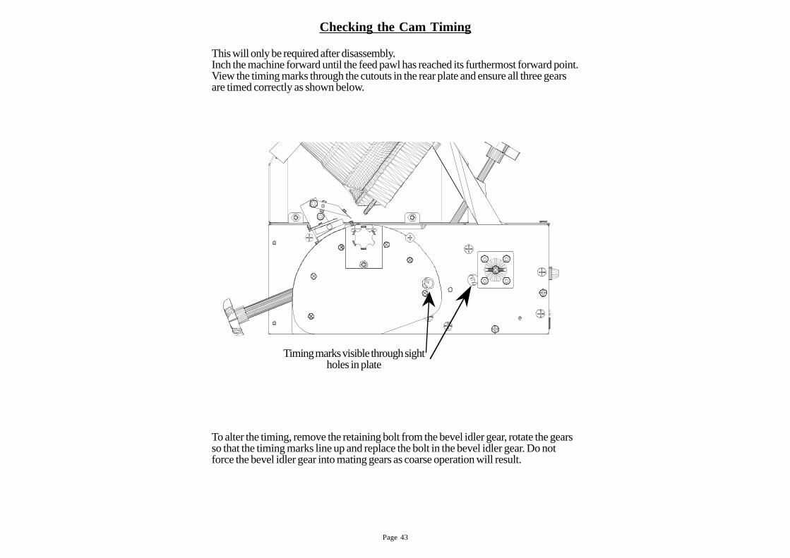
This will only be required after disassembly.Inch the machine forward until the feed pawl has reached its furthermost forward point.View the timing marks through the cutouts in the rear plate and ensure all three gearsare timed correctly as shown below.
To alter the timing, remove the retaining bolt from the bevel idler gear, rotate the gearsso that the timing marks line up and replace the bolt in the bevel idler gear. Do notforce the bevel idler gear into mating gears as coarse operation will result.
Timing marks visible through sight
holes in plate
Checking the Cam Timing