automatic gas firing device bic 960(15-10… · modifications to the automatic gas firing device...
TRANSCRIPT
Subject to modifi cations | EN
Instructions for customerservice engineers
4 205 503 / 10 - 07/12
Modifications to the automatic gas firing device should only be performed by authorised persons. This manual is therefore intended for use by qualified engineers.
Automatic gas firing device BIC 960UltraGas® (15-1000)CompactGas® (200-280)
These instructions apply to the following types:
UltraGas®
10/20/21/30-UltraGas® (15)10/20/21/30-UltraGas® (20)10/20/21/30-UltraGas® (27)10/20/21/30-UltraGas® (35)10/20/21/30-UltraGas® (50)10/20/30-UltraGas® (70)10/20/30-UltraGas® (90)10/11/20/21/30-UltraGas® (125)10/11/20/21/30-UltraGas® (150)10/11/20/21/30-UltraGas® (200)10/11/20/21/30-UltraGas® (250)10/11/20/21/30-UltraGas® (300)10/11/20/21/30-UltraGas® (350)10/11/20/21/30-UltraGas® (400)10/11/20/21/30-UltraGas® (450)10/11/20/21/30-UltraGas® (500)11/20/21/30-UltraGas® (575)10/11/20/21/30-UltraGas® (650)11/20/21/30-UltraGas® (720)21/30-UltraGas® (850)21/30-UltraGas® (1000)
CompactGas®
1-CompactGas® (200-280)
2 4 205 503 / 10
TABle of ConTenTs
1. overview .................................................................................................................................................. 3
2. Description of functions ......................................................................................................................... 42.1 General .................................................................................................................................................................................42.2 Water heater-Charging ........................................................................................................................................................42.3 emission measuring and/or test function for gas valve setting ........................................................................................42.4 Main switch ..........................................................................................................................................................................42.5 Main gas valve (possibly lPG-valve) / heating room fan ...................................................................................................42.6 external burner switch ........................................................................................................................................................42.7 short description of the functions of the BIC 960 automatic firing device .......................................................................52.8 Access to the automatic firing device ................................................................................................................................62.9 Reference values in the case of bus interruption ..............................................................................................................6
3. Description of the parameters ................................................................................................................ 6
4. sensor characteristic curves ................................................................................................................ 12
5. Display of information via the automatic firing device ....................................................................... 13
6. Monitoring of warnings and/or faults ................................................................................................... 14
7. operation using a laptop ...................................................................................................................... 16
8. Interfaces to BIC 960 ............................................................................................................................. 16
9. Connections to the BIC960 ................................................................................................................... 17
10. nTC Protection ...................................................................................................................................... 18
11. frost protection .................................................................................................................................... 19
12. Water pressure ...................................................................................................................................... 19
13. Automatic firing unit BIC 960 - Parameter lists ................................................................................... 2013.1 Generation overview (boiler) .............................................................................................................................................2013.2 Generation overview (automatic gas firing device) .........................................................................................................2113.3 10/20 - UG (15-90) ..............................................................................................................................................................2213.4 21 - UG (15-50) ...................................................................................................................................................................2413.5 30 - UG (15-90) ...................................................................................................................................................................2613.6 10 - UG (125-300) ...............................................................................................................................................................2813.7 10 - UG (350-650) ...............................................................................................................................................................3013.8 11/20/21/30 - UG (125-400) .................................................................................................................................................3213.9 11/20/21/30 - UG (450-1000) ...............................................................................................................................................3413.10 1 - CompactGas® (200-280) ................................................................................................................................................36
34 205 503 / 10
oveRvIeW
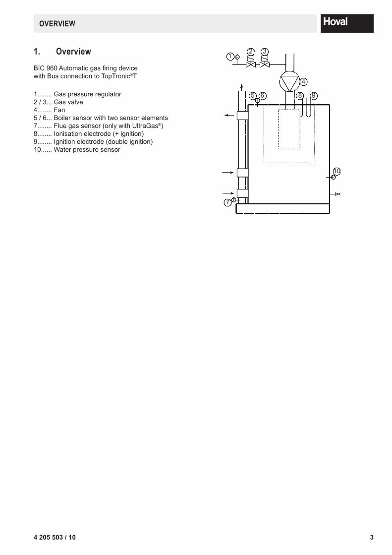
1. overviewBIC 960 Automatic gas firing device with Bus connection to TopTronic®T
1........ Gas pressure regulator2 / 3... Gas valve4........ Fan5 / 6... Boiler sensor with two sensor elements7........ Flue gas sensor (only with UltraGas®)8........ Ionisation electrode (+ ignition)9........ Ignition electrode (double ignition)10...... Water pressure sensor
12 3
P
4
5 6 8 9T
7 T
10P
4 4 205 503 / 10
DesCRIPTIon of fUnCTIons
2. Description of functions
2.1 GeneralThe BIC 960 automatic firing device is designed for use in a modulating gas boiler. There for a PWM fan is triggered by the automatic firing device. This fan has a supply voltage of 230V which is shut-off by an internal relay during downtimes in order to reduce stand-by losses. Fan revolution speed modulation is controlled via an internal PID con-troller in order to maintain the desired flow temperature. The flow reference value is not determined in the automatic firing device, but is calculated and passed on via the heating controller. The BIC 960 automatic firing device can only be used in connection with the TopTronicT/UG heating controller, why the BIC 960 is installed in the background, i.e. the circuit board is not visible from the outside, and complete opera-tion is controlled via the heating controller. The result is a unique principle of operation at boiler level via one inter-face.
2.2 Water heater-ChargingSwitch-over between hot water charging and heating demand is controlled by the TopTronic®T/UG.
2.3 emission measuring and/or test function for gas valve settingThere is a specific key on the heating control unit allocated for emission measurements and/or gas valve adjustment. By using the emission key, a mode of operation is initiated in which the automatic firing device operates in heating mode, with an assigned reference value of 80°C, and in which power output can be adjusted manually using the rotary button. After 20 minutes emission testing operation is ended automatically, and the boiler reverts to the prior operation mode. It is important to ensure that the heat produced during emission testing can also be discharged. When setting boiler performance in terms of percentage values, ensure that 1% is the set minimum performance and 100% is the set maximum performance. In between, there is a linear relationship, on which is it possible to set the desired boiler performance.
2.4 Main switchThe main switch is located on the front of the heating control unit. It takes care for the power supply of the heating control unit and of the automatic firing device, located in the background. When the switch is turned off, frost protec-tion is not active.
2.5 Main gas valve (possibly lPG-valve) / heating room fanAn external main gas valve (possibly a fluid gas valve) and/or a heating room fan can be controlled by the auto-matic firing device. The output is activated a set time (depending on the parameter settings) before activation of the burner start. This application requires a suitable parameterisation of the automatic firing device. Ensure that the TopTronic®T/UG display shows the blocking B:04 (main gas valve) possibly LPG-valve)/ heating room fan) during the burner start delay. Blocking is no longer shown beginning with BIC 960 V.3, but the waiting time has been retained.
2.6 external burner switchLocking or activation of the automatic firing device takes place via the TopTronic®T/UG. The parameters must be set to allow a suitable variable input, as described in the Customer-service technicians introduction to the TopTronic®T/UG.A further possibility is provided by blocking input X9-1/X9-4 via which the automatic firing unit can be set to blocked status. In this case no error message is displayed at the TopTronic®T/UG.
54 205 503 / 10
DesCRIPTIon of fUnCTIons
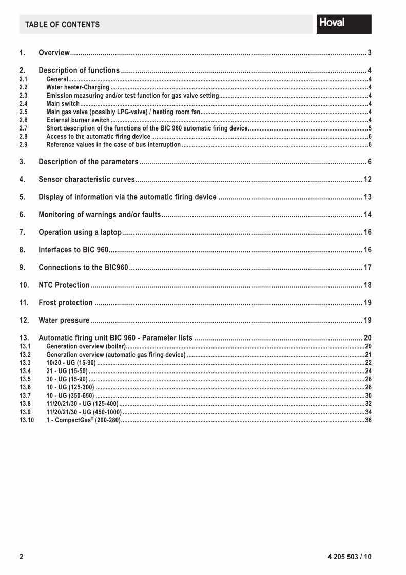
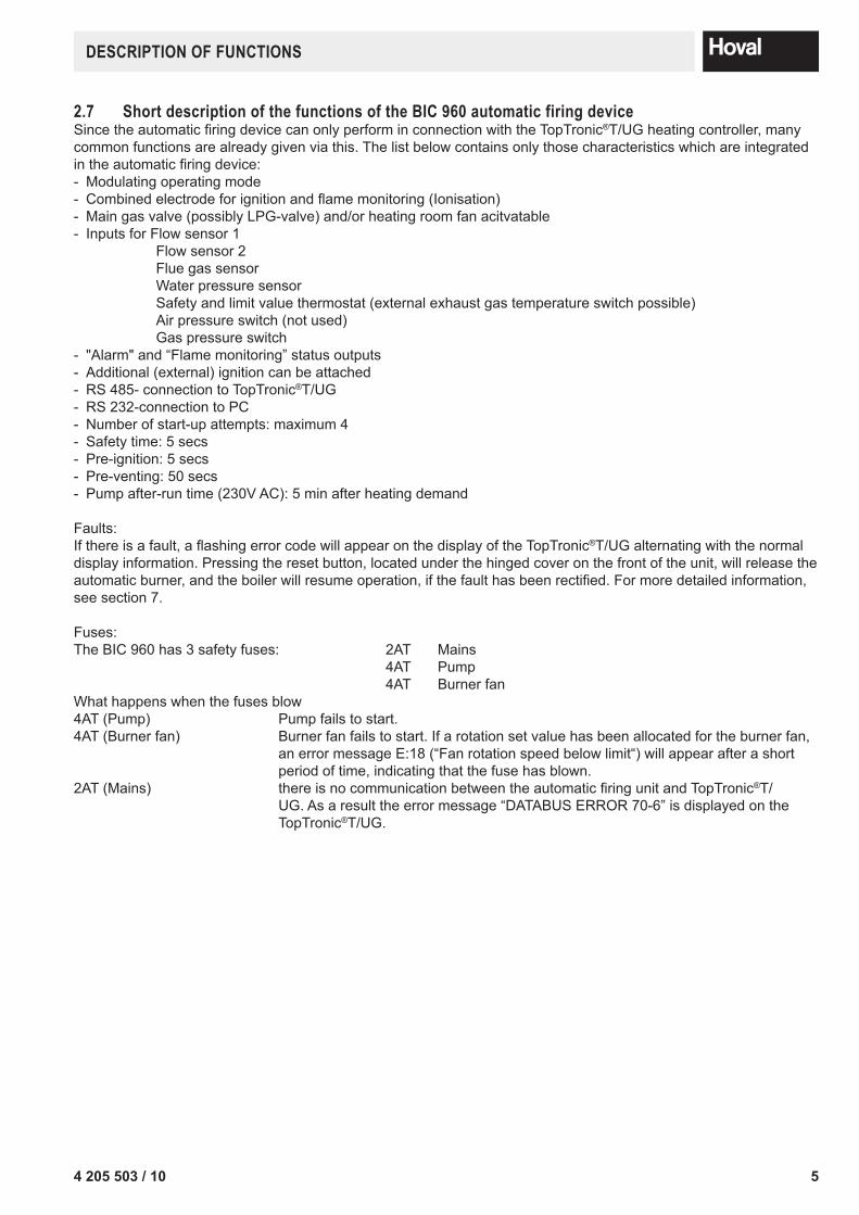
2.7 short description of the functions of the BIC 960 automatic firing deviceSince the automatic firing device can only perform in connection with the TopTronic®T/UG heating controller, many common functions are already given via this. The list below contains only those characteristics which are integrated in the automatic firing device:- Modulating operating mode- Combined electrode for ignition and flame monitoring (Ionisation) - Main gas valve (possibly LPG-valve) and/or heating room fan acitvatable- Inputs for Flow sensor 1 Flow sensor 2 Flue gas sensor Water pressure sensor Safety and limit value thermostat (external exhaust gas temperature switch possible) Air pressure switch (not used) Gas pressure switch- "Alarm" and “Flame monitoring” status outputs- Additional (external) ignition can be attached- RS 485- connection to TopTronic®T/UG- RS 232-connection to PC- Number of start-up attempts: maximum 4- Safety time: 5 secs- Pre-ignition: 5 secs- Pre-venting: 50 secs- Pump after-run time (230V AC): 5 min after heating demand
Faults:If there is a fault, a flashing error code will appear on the display of the TopTronic®T/UG alternating with the normal display information. Pressing the reset button, located under the hinged cover on the front of the unit, will release the automatic burner, and the boiler will resume operation, if the fault has been rectified. For more detailed information, see section 7.
Fuses:The BIC 960 has 3 safety fuses: 2AT Mains 4AT Pump 4AT Burner fanWhat happens when the fuses blow 4AT (Pump) Pump fails to start.4AT (Burner fan) Burner fan fails to start. If a rotation set value has been allocated for the burner fan,
an error message E:18 (“Fan rotation speed below limit“) will appear after a short period of time, indicating that the fuse has blown.
2AT (Mains) there is no communication between the automatic firing unit and TopTronic®T/UG. As a result the error message “DATABUS ERROR 70-6” is displayed on the TopTronic®T/UG.

6 4 205 503 / 10
DesCRIPTIon of The PARAMeTeRs
2.8 Access to the automatic firing deviceThe boiler is operated in the same way as described in the operating instructions of the TopTronic®T/UG. The auto-matic firing device operating in the background can be accessed using a special menu tree on the TopTronic®T/UG. This menu allows access to the “BOILER CONTR” submenu, where it is possible to view an information level and a parameter level. „INFORMATION“: As well as actual system values, which can be displayed via the Info-key, this option also al-
lows specific state variables to be viewed. (for further information see “Display of Information from the Automatic Firing Device”)„PARAMETER“: Depending on the user level, which can be reached using various code levels, it is possible to
amend certain parameters. If using a Notebook (SITBIC960lab - Software), parameter settings are also dependant on the code level. (for more information about controlling the automatic firing device using a laptop, see "operating using a laptop").
Attention: After a Reset at the TopTronicT® the parameters ad the automatic gas firing devise will not be resetted to basic setting.
2.9 Reference values in the case of bus interruptionIf there is an interruption in the bus connection between the TopTronicT®/UG and the automatic firing device, the automatic firing device begins to operate in emergency mode, which means that a set value of 75°C (parameter 8) is adopted. In addition, the error message “DATABUS ERROR 70-6” is displayed on the TopTronic®T/UG.
3. Description of the parametersThe parameters can be set using the parameter tree of the TopTronicT®/UG, and also using the SITBIC960lab - Soft-ware on a Notebook. On SITBIC960lab-software, the parameters are not indicated with a number, but with a number and letter combination, which can be seen below in brackets.
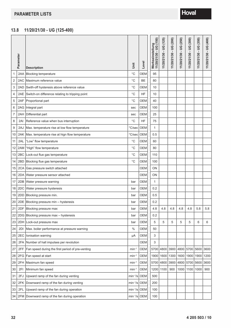
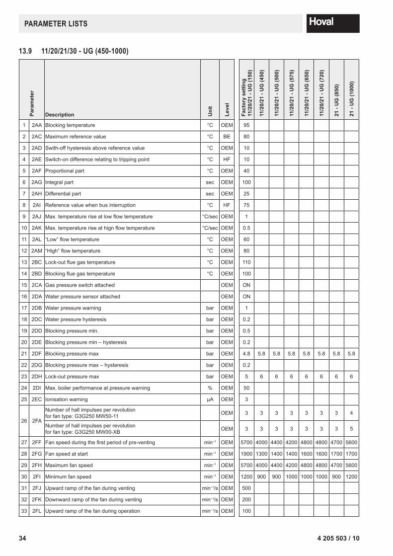
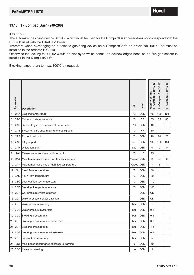
Parameter 1 (2AA): Blocking temperature The value of the parameter determines at what boiler sensor temperature the burner is switched off. (“B:08“)
Parameter 2 (2AC): Maximum reference value The reference value, which is set in manual operation, and/or which is calculated by the TopTronicT®/UG in auto-matic operation, is here limited to a set value.
Parameter 3 (2AD): Switch-off hysteresis above reference value If during a heat demand, the temperature rises above the reference value plus the value entered here, the burner switches off. See functional drawing 1.
Parameter 4 (2AE): Switch-on difference relating to tripping point When the temperature falls below the reference value + switch-off hysteresis (Parameter 3) – switch-on difference (Parameter 4), the burner demand is activated. See functional drawing 1.
Temperature °C
Par. 3
Par. 4
Functional drawing 1
74 205 503 / 10
DesCRIPTIon of The PARAMeTeRs
Parameter 5 (2AF): Proportional partThe Proportional part in heating operation is a boiler specific value (not plant specific) and must not be changed.
Parameter 6 (2AG): Integral partThe Integral part in heating operation is a boiler specific value (not plant specific) and must not be changed.
Parameter 7 (2AH): Differential partThe Differential part in heating operation is a boiler specific value (not plant specific) and must not be changed.
Parameter 8 (2AI): Reference value when bus-interruptionIf there is no bus connection between the automatic firing device and the TopTronic®T/UG, the automatic firing de-vice adopts the reference value entered here.
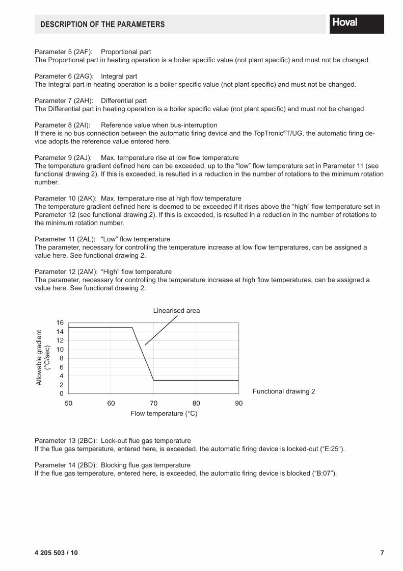
Parameter 9 (2AJ): Max. temperature rise at low flow temperatureThe temperature gradient defined here can be exceeded, up to the “low” flow temperature set in Parameter 11 (see functional drawing 2). If this is exceeded, is resulted in a reduction in the number of rotations to the minimum rotation number.
Parameter 10 (2AK): Max. temperature rise at high flow temperatureThe temperature gradient defined here is deemed to be exceeded if it rises above the “high” flow temperature set in Parameter 12 (see functional drawing 2). If this is exceeded, is resulted in a reduction in the number of rotations to the minimum rotation number.
Parameter 11 (2AL): “Low” flow temperatureThe parameter, necessary for controlling the temperature increase at low flow temperatures, can be assigned a value here. See functional drawing 2.
Parameter 12 (2AM): “High” flow temperatureThe parameter, necessary for controlling the temperature increase at high flow temperatures, can be assigned a value here. See functional drawing 2.
Linearised area
02468
10121416
50 60 70 80 90
Allo
wab
le g
radi
ent
(°C
/sec
)
Flow temperature (°C)
Functional drawing 2
Parameter 13 (2BC): Lock-out flue gas temperatureIf the flue gas temperature, entered here, is exceeded, the automatic firing device is locked-out (“E:25“).
Parameter 14 (2BD): Blocking flue gas temperatureIf the flue gas temperature, entered here, is exceeded, the automatic firing device is blocked (“B:07”).
8 4 205 503 / 10
DesCRIPTIon of The PARAMeTeRs
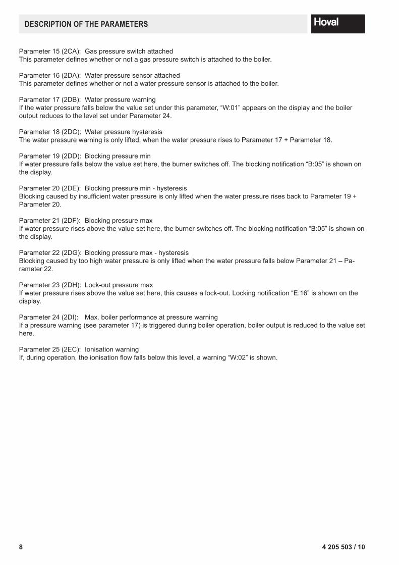
Parameter 15 (2CA): Gas pressure switch attachedThis parameter defines whether or not a gas pressure switch is attached to the boiler.
Parameter 16 (2DA): Water pressure sensor attachedThis parameter defines whether or not a water pressure sensor is attached to the boiler.
Parameter 17 (2DB): Water pressure warningIf the water pressure falls below the value set under this parameter, “W:01” appears on the display and the boiler output reduces to the level set under Parameter 24.
Parameter 18 (2DC): Water pressure hysteresisThe water pressure warning is only lifted, when the water pressure rises to Parameter 17 + Parameter 18.
Parameter 19 (2DD): Blocking pressure minIf water pressure falls below the value set here, the burner switches off. The blocking notification “B:05” is shown on the display.
Parameter 20 (2DE): Blocking pressure min - hysteresisBlocking caused by insufficient water pressure is only lifted when the water pressure rises back to Parameter 19 + Parameter 20.
Parameter 21 (2DF): Blocking pressure maxIf water pressure rises above the value set here, the burner switches off. The blocking notification “B:05” is shown on the display.
Parameter 22 (2DG): Blocking pressure max - hysteresisBlocking caused by too high water pressure is only lifted when the water pressure falls below Parameter 21 – Pa-rameter 22.
Parameter 23 (2DH): Lock-out pressure maxIf water pressure rises above the value set here, this causes a lock-out. Locking notification “E:16” is shown on the display.
Parameter 24 (2DI): Max. boiler performance at pressure warningIf a pressure warning (see parameter 17) is triggered during boiler operation, boiler output is reduced to the value set here.
Parameter 25 (2EC): Ionisation warningIf, during operation, the ionisation flow falls below this level, a warning “W:02” is shown.
94 205 503 / 10
DesCRIPTIon of The PARAMeTeRs
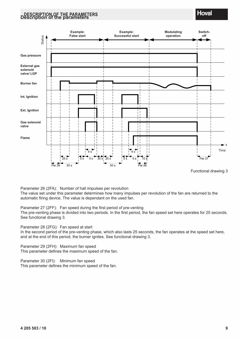
Parameter 26 (2FA): Number of hall impulses per revolutionThe value set under this parameter determines how many impulses per revolution of the fan are returned to the automatic firing device. The value is dependant on the used fan.
Parameter 27 (2FF): Fan speed during the first period of pre-ventingThe pre-venting phase is divided into two periods. In the first period, the fan speed set here operates for 25 seconds. See functional drawing 3.
Parameter 28 (2FG): Fan speed at startIn the second period of the pre-venting phase, which also lasts 25 seconds, the fan operates at the speed set here, and at the end of this period, the burner ignites. See functional drawing 3.
Parameter 29 (2FH): Maximum fan speedThis parameter defines the maximum speed of the fan.
Parameter 30 (2FI): Minimum fan speedThis parameter defines the minimum speed of the fan.
Description of the parameters
Gas pressure
External gas solenoid valve/ LGP
Burner fan
Int. Ignition
Gas sole noid valve
Flame
t
Par.39
25 s
50 s
5 s
4 s
5 s 30 s 25 s
50 s
5 s
4 s
5 s 10 s
Par.48
Par.37
Example:False start
Example:Successful start
Modulatingoperation
Switch-off
Time
Ext. Ignition
Functional drawing 3
Sta
tus
10 4 205 503 / 10
DesCRIPTIon of The PARAMeTeRs
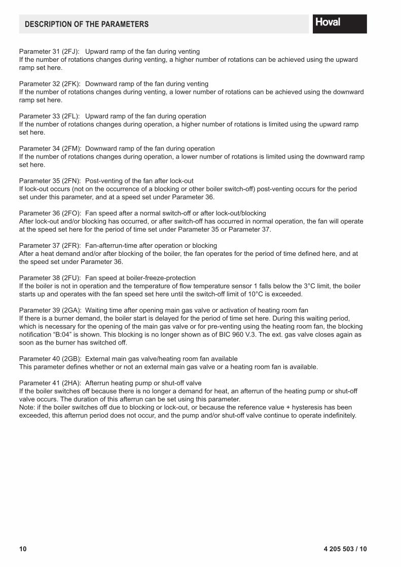
Parameter 31 (2FJ): Upward ramp of the fan during ventingIf the number of rotations changes during venting, a higher number of rotations can be achieved using the upward ramp set here.
Parameter 32 (2FK): Downward ramp of the fan during ventingIf the number of rotations changes during venting, a lower number of rotations can be achieved using the downward ramp set here.
Parameter 33 (2FL): Upward ramp of the fan during operationIf the number of rotations changes during operation, a higher number of rotations is limited using the upward ramp set here.
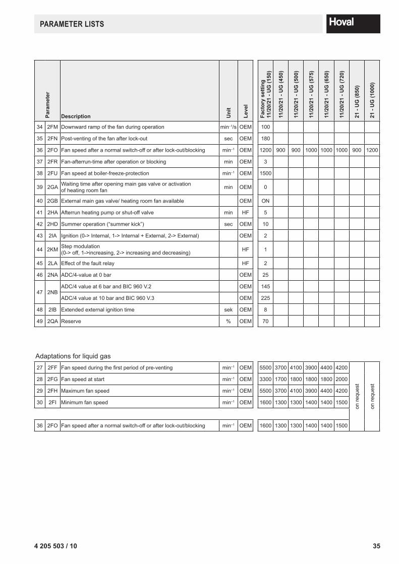
Parameter 34 (2FM): Downward ramp of the fan during operationIf the number of rotations changes during operation, a lower number of rotations is limited using the downward ramp set here.
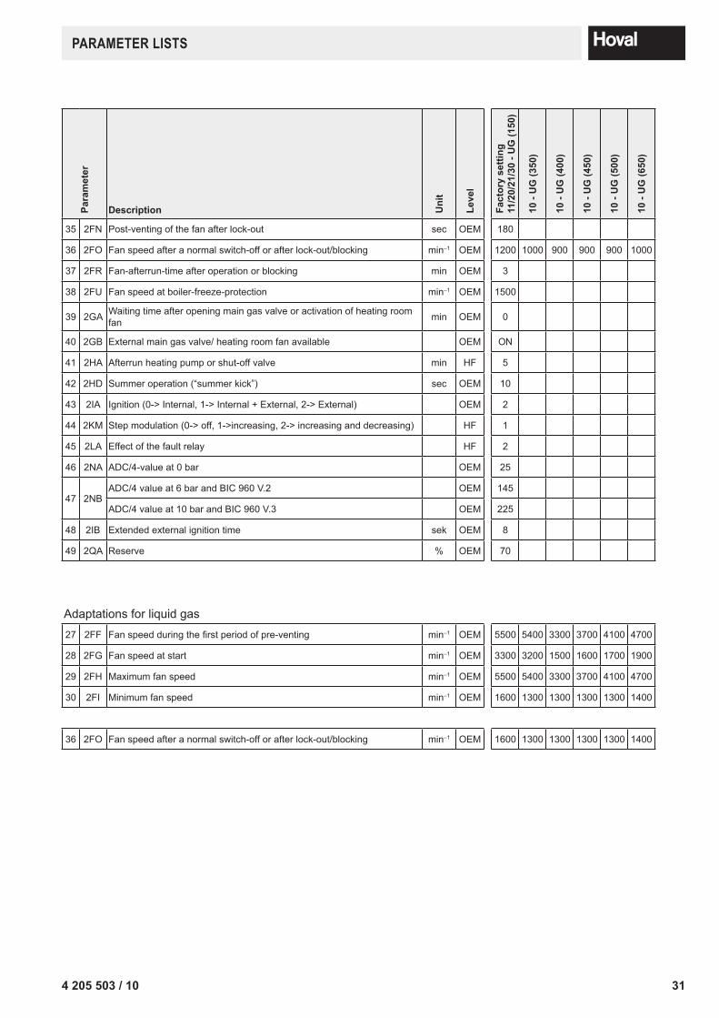
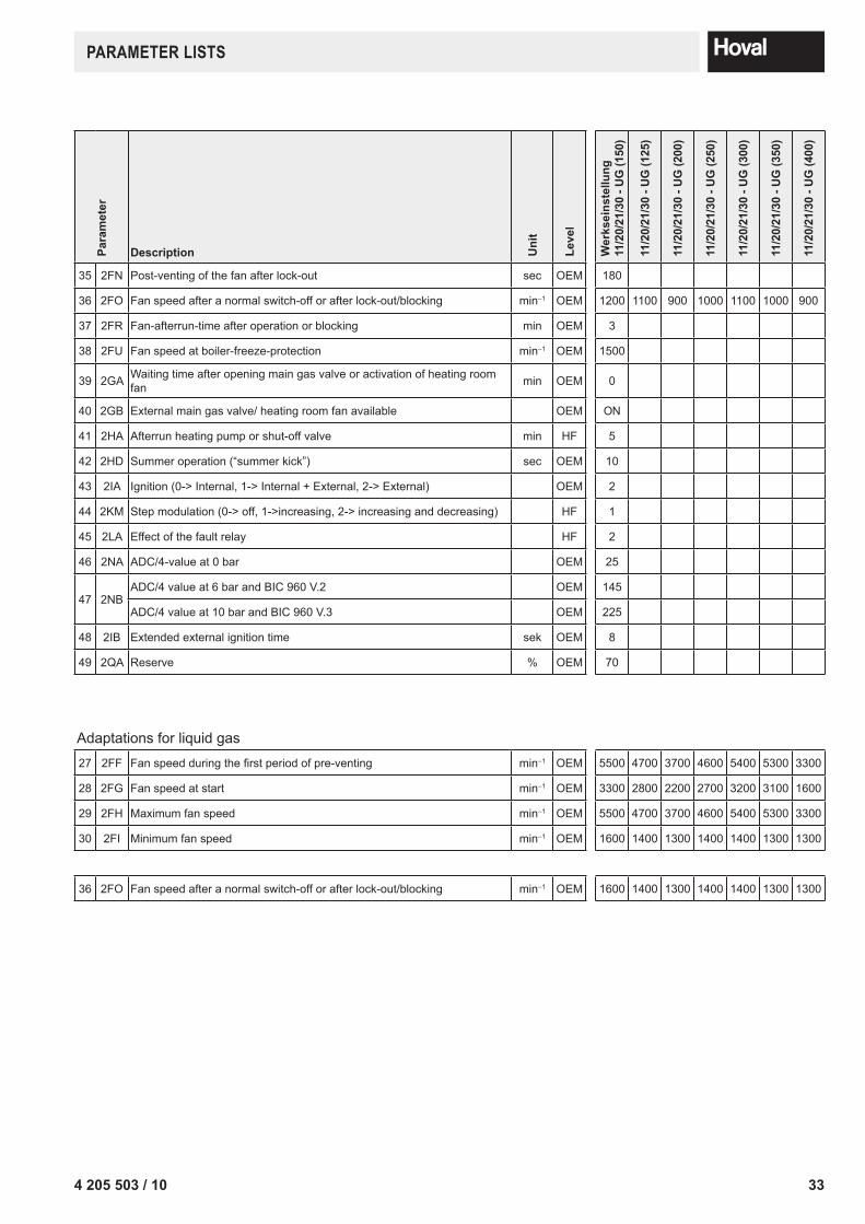
Parameter 35 (2FN): Post-venting of the fan after lock-outIf lock-out occurs (not on the occurrence of a blocking or other boiler switch-off) post-venting occurs for the period set under this parameter, and at a speed set under Parameter 36.
Parameter 36 (2FO): Fan speed after a normal switch-off or after lock-out/blockingAfter lock-out and/or blocking has occurred, or after switch-off has occurred in normal operation, the fan will operate at the speed set here for the period of time set under Parameter 35 or Parameter 37.
Parameter 37 (2FR): Fan-afterrun-time after operation or blockingAfter a heat demand and/or after blocking of the boiler, the fan operates for the period of time defined here, and at the speed set under Parameter 36.
Parameter 38 (2FU): Fan speed at boiler-freeze-protectionIf the boiler is not in operation and the temperature of flow temperature sensor 1 falls below the 3°C limit, the boiler starts up and operates with the fan speed set here until the switch-off limit of 10°C is exceeded.
Parameter 39 (2GA): Waiting time after opening main gas valve or activation of heating room fanIf there is a burner demand, the boiler start is delayed for the period of time set here. During this waiting period, which is necessary for the opening of the main gas valve or for pre-venting using the heating room fan, the blocking notification “B:04” is shown. This blocking is no longer shown as of BIC 960 V.3. The ext. gas valve closes again as soon as the burner has switched off.
Parameter 40 (2GB): External main gas valve/heating room fan availableThis parameter defines whether or not an external main gas valve or a heating room fan is available.
Parameter 41 (2HA): Afterrun heating pump or shut-off valveIf the boiler switches off because there is no longer a demand for heat, an afterrun of the heating pump or shut-off valve occurs. The duration of this afterrun can be set using this parameter.Note: if the boiler switches off due to blocking or lock-out, or because the reference value + hysteresis has been exceeded, this afterrun period does not occur, and the pump and/or shut-off valve continue to operate indefinitely.
114 205 503 / 10
DesCRIPTIon of The PARAMeTeRs
Parameter 42 (2HD): Summer operation (“summerkick”)Every 24 hours, the pump and/or shut-off valve turns on for the period of time entered under this parameter.
Parameter 43 (2IA): IgnitionThis parameter allows the following ignition options to be set: 0 Ignition with internal ignition transformer1 Ignition with internal and external ignition transformer2 Ignition with external ignition transformerParameter 44 (2KM): Step modulationThis parameter allows the step modulation to be turned off or specially defined. 0 Step modulation off1 Step modulation increasing2 Step modulation increasing and decreasing (not used)Step modulation limits the boiler performance after the start of heating operation
Parameter 45 (2LA): Effect of the fault relay This parameter defines the effect of the fault relay.0 Closes if there is a warning/blocking/fault1 Closes if there is a blocking/fault2 Closes if there is a fault
Parameter 46 (2NA): Setting water pressure sensor - ADC/4-value at 0 barThe set values of the water pressure sensor are used to indicate the actual water pressure via the voltage delivered from the sensor. The value set here is responsible for the correct display of water pressure at 0 bar water pressure. Between the two available set values (set value at 0 bar and 6 bar) there is a linear relationship.
Parameter 47 (2NB): Setting water pressure sensor - ADC/4-value at 10 barThe set values of the water pressure sensor are used to indicate the actual water pressure via the voltage delivered from the sensor. The value set here is responsible for the correct display of water pressure at 10 bar water pressure Between the two available set values (set value at 0 bar and 10 bar) there is a linear relationship.
Parameter 48 (2IB): Extended external ignition timeIf the parameters have been set for an external ignition (parameter 43 = 1 or 2), this parameter is used to set how long it should stay active after the internal ignition time expires. This function is used to keep the stabilising flap closed longer (if present).
Parameter 49 (2QA): Reserve(no effects)
12 4 205 503 / 10
sensoR ChARACTeRIsTIC CURves
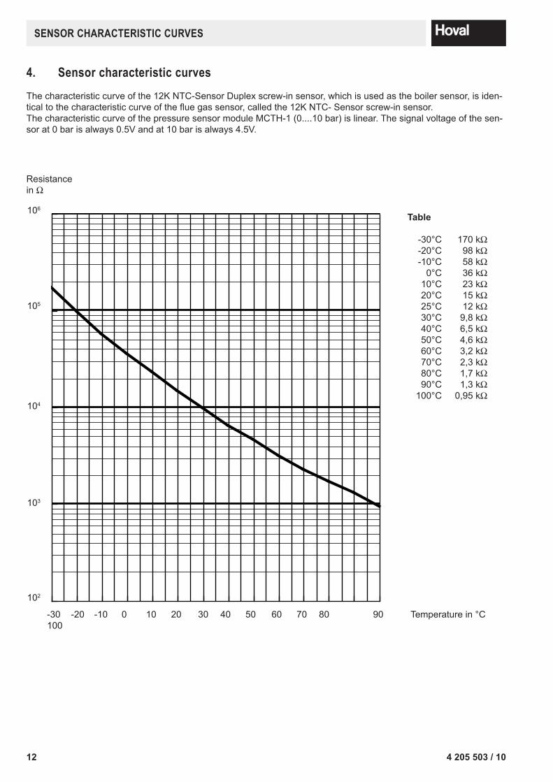
4. sensor characteristic curvesThe characteristic curve of the 12K NTC-Sensor Duplex screw-in sensor, which is used as the boiler sen sor, is iden-tical to the characteristic curve of the flue gas sensor, called the 12K NTC- Sensor screw-in sen sor.The characteristic curve of the pressure sensor module MCTH-1 (0....10 bar) is linear. The signal voltage of the sen-sor at 0 bar is always 0.5V and at 10 bar is always 4.5V.
-30 -20 -10 0 10 20 30 40 50 60 70 80 90 100
102
103
104
105
106
Resistance in Ω
Temperature in °C
Table
-30°C 170 kΩ -20°C 98 kΩ -10°C 58 kΩ 0°C 36 kΩ 10°C 23 kΩ 20°C 15 kΩ 25°C 12 kΩ 30°C 9,8 kΩ 40°C 6,5 kΩ 50°C 4,6 kΩ 60°C 3,2 kΩ 70°C 2,3 kΩ 80°C 1,7 kΩ 90°C 1,3 kΩ 100°C 0,95 kΩ
134 205 503 / 10
DIsPlAy of InfoRMATIon vIA The AUToMATIC fIRInG DevICe
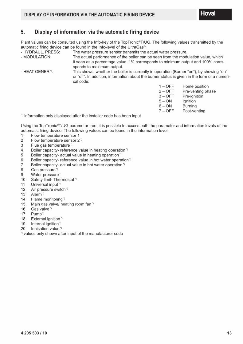
5. Display of information via the automatic firing devicePlant values can be consulted using the Info-key of the TopTronic®T/UG. The following values transmitted by the automatic firing device can be found in the Info-level of the UltraGas®:- HYDRAUL. PRESS: The water pressure sensor transmits the actual water pressure.- MODULATION: The actual performance of the boiler can be seen from the modulation value, which
it seen as a percentage value. 1% corresponds to minimum output and 100% corre-sponds to maximum output.
- HEAT GENER *): This shows, whether the boiler is currently in operation (Burner “on”), by showing “on” or “off”. In addition, information about the burner status is given in the form of a numeri-cal code:
1 – OFF Home position 2 – OFF Pre-venting phase 3 – OFF Pre-ignition 5 – ON Ignition 6 – ON Burning 7 – OFF Post-venting *) information only displayed after the installer code has been input
Using the TopTronic®T/UG parameter tree, it is possible to access both the parameter and information levels of the automatic firing device. The following values can be found in the information level: 1 Flow temperature sensor 12 Flow temperature sensor 2 *)
3 Flue gas temperature *)
4 Boiler capacity- reference value in heating operation *)
5 Boiler capacity- actual value in heating operation *)
6 Boiler capacity- reference value in hot water operation *)
7 Boiler capacity- actual value in hot water operation *)
8 Gas pressure *)
9 Water pressure *)
10 Safety limit- Thermostat *)
11 Universal input *)
12 Air pressure switch *)
13 Alarm *)
14 Flame monitoring *)
15 Main gas valve/ heating room fan *)
16 Gas valve *)
17 Pump *)
18 External ignition *)
19 Internal ignition *)
20 Ionisation value *)
*) values only shown after input of the manufacturer code
14 4 205 503 / 10
MonIToRInG of WARnInGs AnD/oR fAUlTs
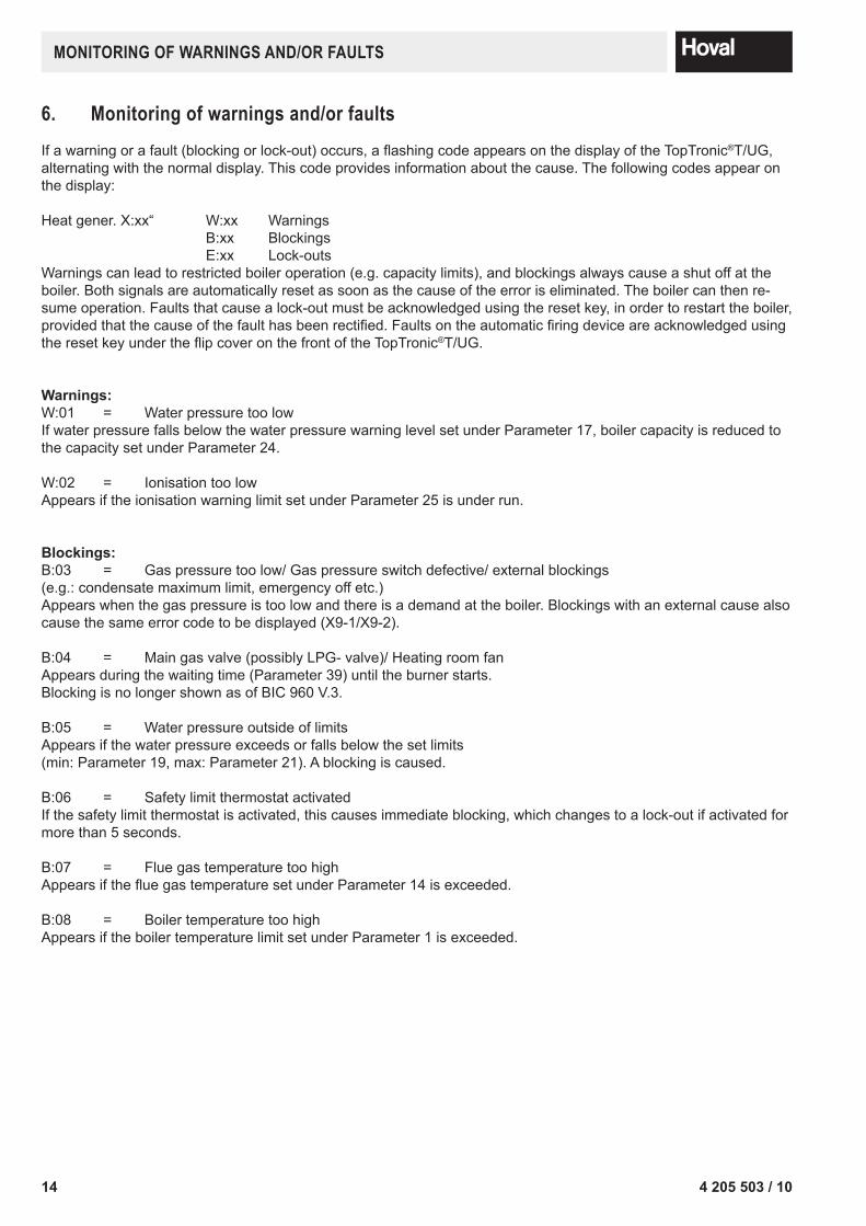
6. Monitoring of warnings and/or faultsIf a warning or a fault (blocking or lock-out) occurs, a flashing code appears on the display of the TopTronic®T/UG, alternating with the normal display. This code provides information about the cause. The following codes appear on the display:
Heat gener. X:xx“ W:xx Warnings B:xx Blockings E:xx Lock-outsWarnings can lead to restricted boiler operation (e.g. capacity limits), and blockings always cause a shut off at the boi ler. Both signals are automatically reset as soon as the cause of the error is eliminated. The boi ler can then re-sume operation. Faults that cause a lock-out must be acknowledged using the reset key, in order to restart the boiler, provided that the cause of the fault has been rectified. Faults on the automatic firing device are acknowledged using the reset key under the flip cover on the front of the TopTronic®T/UG.
Warnings:W:01 = Water pressure too lowIf water pressure falls below the water pressure warning level set under Parameter 17, boiler capacity is reduced to the capacity set under Parameter 24.
W:02 = Ionisation too lowAppears if the ionisation warning limit set under Parameter 25 is under run.
Blockings:B:03 = Gas pressure too low/ Gas pressure switch defective/ external blockings (e.g.: condensate maximum limit, emergency off etc.)Appears when the gas pressure is too low and there is a demand at the boiler. Blockings with an external cause also cause the same error code to be displayed (X9-1/X9-2).
B:04 = Main gas valve (possibly LPG- valve)/ Heating room fan Appears during the waiting time (Parameter 39) until the burner starts.Blocking is no longer shown as of BIC 960 V.3.
B:05 = Water pressure outside of limitsAppears if the water pressure exceeds or falls below the set limits (min: Parameter 19, max: Parameter 21). A blocking is caused.
B:06 = Safety limit thermostat activatedIf the safety limit thermostat is activated, this causes immediate blocking, which changes to a lock-out if activated for more than 5 seconds.
B:07 = Flue gas temperature too highAppears if the flue gas temperature set under Parameter 14 is exceeded.
B:08 = Boiler temperature too highAppears if the boiler temperature limit set under Parameter 1 is exceeded.
154 205 503 / 10
MonIToRInG of WARnInGs AnD/oR fAUlTs
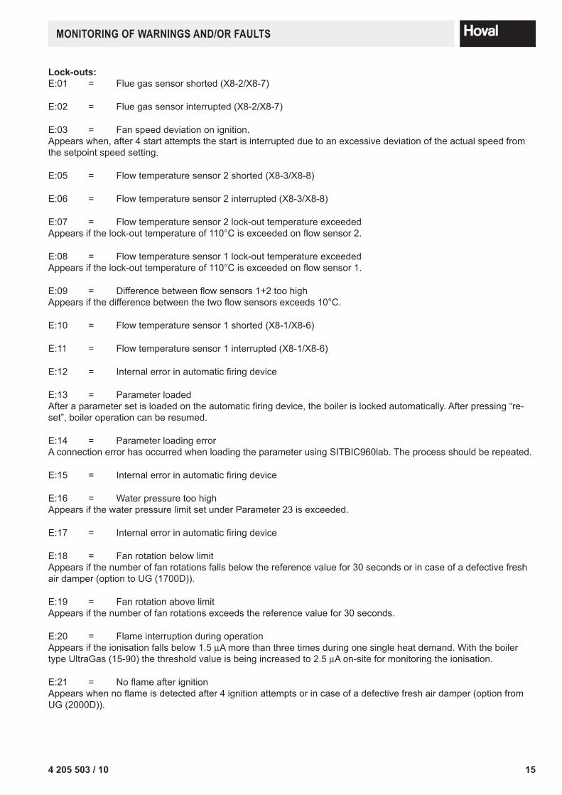
Lock-outs:E:01 = Flue gas sensor shorted (X8-2/X8-7)
E:02 = Flue gas sensor interrupted (X8-2/X8-7)
E:03 = Fan speed deviation on ignition.Appears when, after 4 start attempts the start is interrupted due to an excessive deviation of the actual speed from the setpoint speed setting.
E:05 = Flow temperature sensor 2 shorted (X8-3/X8-8)
E:06 = Flow temperature sensor 2 interrupted (X8-3/X8-8)
E:07 = Flow temperature sensor 2 lock-out temperature exceeded Appears if the lock-out temperature of 110°C is exceeded on flow sensor 2.
E:08 = Flow temperature sensor 1 lock-out temperature exceededAppears if the lock-out temperature of 110°C is exceeded on flow sensor 1.
E:09 = Difference between flow sensors 1+2 too highAppears if the difference between the two flow sensors exceeds 10°C.
E:10 = Flow temperature sensor 1 shorted (X8-1/X8-6)
E:11 = Flow temperature sensor 1 interrupted (X8-1/X8-6)
E:12 = Internal error in automatic firing device
E:13 = Parameter loadedAfter a parameter set is loaded on the automatic firing device, the boiler is locked automatically. After pressing “re-set”, boiler operation can be resumed.
E:14 = Parameter loading errorA connection error has occurred when loading the parameter using SITBIC960lab. The process should be repeated.
E:15 = Internal error in automatic firing device
E:16 = Water pressure too highAppears if the water pressure limit set under Parameter 23 is exceeded.
E:17 = Internal error in automatic firing device
E:18 = Fan rotation below limitAppears if the number of fan rotations falls below the reference value for 30 seconds or in case of a defective fresh air damper (option to UG (1700D)).
E:19 = Fan rotation above limitAppears if the number of fan rotations exceeds the reference value for 30 seconds.
E:20 = Flame interruption during operationAppears if the ionisation falls below 1.5 µA more than three times during one single heat demand. With the boiler type UltraGas (15-90) the threshold value is being increased to 2.5 µA on-site for monitoring the ionisation.
E:21 = No flame after ignitionAppears when no flame is detected after 4 ignition attempts or in case of a defective fresh air damper (option from UG (2000D)).
16 4 205 503 / 10
oPeRATIon UsInG A lAPToP
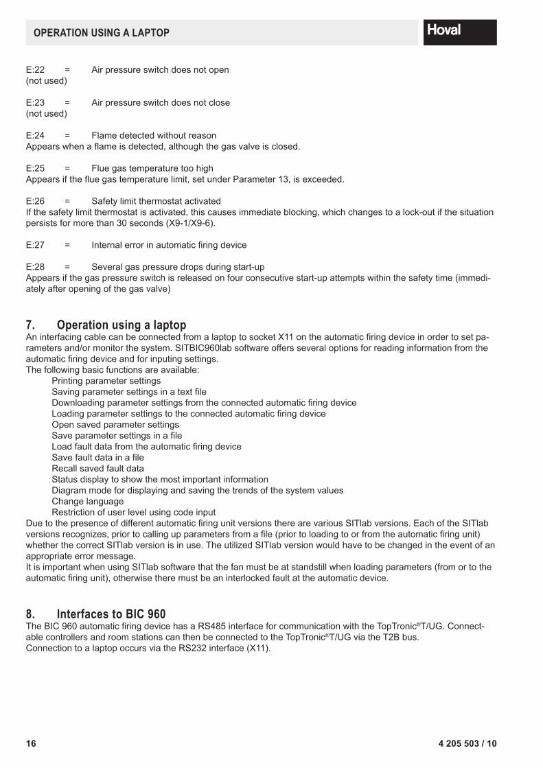
E:22 = Air pressure switch does not open(not used)
E:23 = Air pressure switch does not close(not used)
E:24 = Flame detected without reasonAppears when a flame is detected, although the gas valve is closed.
E:25 = Flue gas temperature too highAppears if the flue gas temperature limit, set under Parameter 13, is exceeded.
E:26 = Safety limit thermostat activatedIf the safety limit thermostat is activated, this causes immediate blocking, which changes to a lock-out if the situation persists for more than 30 seconds (X9-1/X9-6).
E:27 = Internal error in automatic firing device
E:28 = Several gas pressure drops during start-upAppears if the gas pressure switch is released on four consecutive start-up attempts within the safety time (immedi-ately after opening of the gas valve)
7. operation using a laptopAn interfacing cable can be connected from a laptop to socket X11 on the automatic firing device in order to set pa-rameters and/or monitor the system. SITBIC960lab software offers several options for reading in formation from the automatic firing device and for inputing settings. The following basic functions are available: Printing parameter settings Saving parameter settings in a text file Downloading parameter settings from the connected automatic firing device Loading parameter settings to the connected automatic firing device Open saved parameter settings Save parameter settings in a file Load fault data from the automatic firing device Save fault data in a file Recall saved fault data Status display to show the most important information Diagram mode for displaying and saving the trends of the system values Change language Restriction of user level using code inputDue to the presence of different automatic firing unit versions there are various SITlab versions. Each of the SITlab versions recognizes, prior to calling up parameters from a file (prior to loading to or from the automatic firing unit) whether the correct SITlab version is in use. The utilized SITlab version would have to be changed in the event of an appropriate error message.It is important when using SITlab software that the fan must be at standstill when loading parameters (from or to the automatic firing unit), otherwise there must be an interlocked fault at the automatic device.
8. Interfaces to BIC 960The BIC 960 automatic firing device has a RS485 interface for communication with the TopTronic®T/UG. Connect-able controllers and room stations can then be connected to the TopTronic®T/UG via the T2B bus. Connection to a laptop occurs via the RS232 interface (X11).
174 205 503 / 10
ConneCTIons To The BIC960
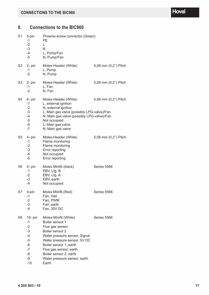
9. Connections to the BIC960X1 5-pin Phoenix-screw connector (Green) -1 PE -2 L -3 N -4 L, Pump/Fan -5 N, Pump/Fan
X2 2- pin Molex-Header (White) 5,08 mm (0.2’’) Pitch -1 L, Pump -2 N, Pump
X3 2- pin Molex-Header (White) 5,08 mm (0.2’’) Pitch -1 L, Fan -2 N, Fan
X4 6- pin Molex-Header (White) 5,08 mm (0,2’’) Pitch -1 L, external ignition -2 N, external ignition -3 L, Main gas valve (possibly LPG-valve)/Fan -4 N, Main gas valve (possibly LPG-valve)/Fan -5 Not occupied -6 L, Main gas valve -7 N, Main gas valve
X5 4- pin Molex-Header (White) 5,08 mm (0.2’’) Pitch -1 Flame monitoring -2 Flame monitoring -3 Error reporting -4 Not occupied -5 Error reporting
X6 4- pin Molex Minifit (black) Series 5566 -1 EBV, Ltg. B -2 EBV, Ltg. A -3 EBV, earth -4 Not occupied
X7 4-pin Molex Minifit (Red) Series 5566 -1 Fan, Hall -2 Fan, PWM -3 Fan, earth -4 Fan, 30V DC
X8 10- pin Molex-Minifit (White) Series 5566 -1 Boiler sensor 1 -2 Flue gas sensor -3 Boiler sensor 2 -4 Water pressure sensor, Signal -5 Water pressure sensor, 5V DC -6 Boiler sensor 1, earth -7 Flue gas sensor, earth -8 Boiler sensor 2, earth -9 Water pressure sensor, earth -10 Earth
18 4 205 503 / 10
nTC PRoTeCTIon
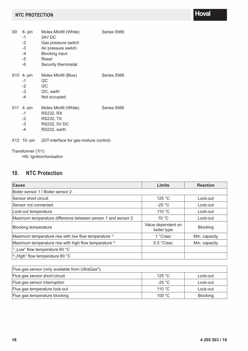
X9 6- pin Molex-Minifit (White) Series 5566 -1 24V DC -2 Gas pressure switch -3 Air pressure switch -4 Blocking input -5 Reset -6 Security thermostat
X10 4- pin Molex Minifit (Blue) Series 5566 -1 I2C -2 I2C -3 I2C, earth -4 Not occupied
X11 4- pin Molex Minifit (White) Series 5566 -1 RS232, RX -2 RS232, TX -3 RS232, 5V DC -4 RS232, earth
X12 10- pin (SIT-interface for gas-mixture control) Transformer (Tr1) HS- Ignition/Ionisation
10. nTC Protection
Cause Limits ReactionBoiler sensor 1 / Boiler sensor 2:Sensor short circuit 125 °C Lock-outSensor not connected -25 °C Lock-outLock-out temperature 110 °C Lock-outMaximum temperature difference between sensor 1 and sensor 2 10 °C Lock-out
Blocking temperature Value dependent on boiler type Blocking
Maximum temperature rise with low flow temperature 1) 1 °C/sec Min. capacityMaximum temperature rise with high flow temperature 2) 0.5 °C/sec Min. capacity1) „Low” flow temperature 60 °C2) „High” flow temperature 80 °C
Flue gas sensor (only available from UltraGas®):Flue gas sensor short-circuit 125 °C Lock-outFlue gas sensor interruption -25 °C Lock-outFlue gas temperature lock-out 110 °C Lock-outFlue gas temperature blocking 100 °C Blocking
194 205 503 / 10
fRosT PRoTeCTIon
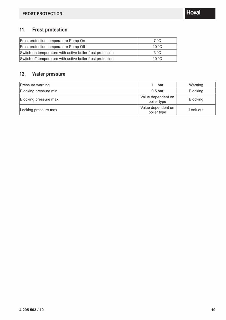
11. frost protection
Frost protection temperature Pump On 7 °CFrost protection temperature Pump Off 10 °CSwitch-on temperature with active boiler frost protection 3 °CSwitch-off temperature with active boiler frost protection 10 °C
12. Water pressure
Pressure warning 1 bar WarningBlocking pressure min 0.5 bar Blocking
Blocking pressure max Value dependent on boiler type Blocking
Locking pressure max Value dependent on boiler type Lock-out
20 4 205 503 / 10
PARAMeTeR lIsTs
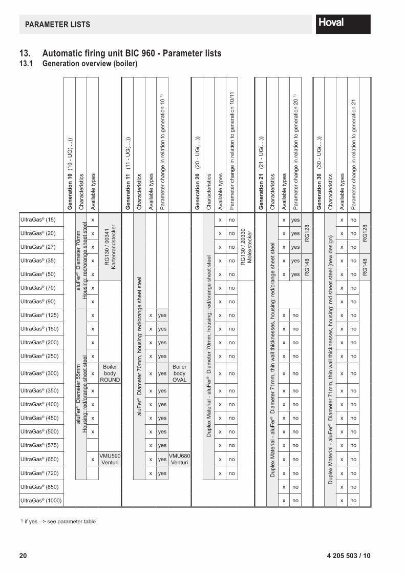
13. Automatic firing unit BIC 960 - Parameter lists13.1 Generation overview (boiler)
Gen
erat
ion
10 (
10 -
UG
(....)
)
Cha
ract
eris
tics
Avai
labl
e ty
pes
Gen
erat
ion
11
(11
- UG
(....)
)
Cha
ract
eris
tics
Avai
labl
e ty
pes
Par
amet
er c
hang
e in
rela
tion
to g
ener
atio
n 10
1)
Gen
erat
ion
20
(20
- UG
(....)
)
Cha
ract
eris
tics
Avai
labl
e ty
pes
Par
amet
er c
hang
e in
rela
tion
to g
ener
atio
n 10
/11
Gen
erat
ion
21
(21
- UG
(....)
)
Cha
ract
eris
tics
Avai
labl
e ty
pes
Par
amet
er c
hang
e in
rela
tion
to g
ener
atio
n 20
1)
Gen
erat
ion
30
(30
- UG
(....)
)
Cha
ract
eris
tics
Avai
labl
e ty
pes
Par
amet
er c
hang
e in
rela
tion
to g
ener
atio
n 21
UltraGas® (15)
aluF
er® D
iam
eter
70m
mH
ousi
ng: r
ed/o
rang
e sh
eet s
teel
x
RG
130
/ 003
41K
arte
nran
dste
cker
aluF
er® D
iam
eter
70m
m, h
ousi
ng: r
ed/o
rang
e sh
eet s
teel
Dup
lex
Mat
eria
l - a
luFe
r® D
iam
eter
70m
m, h
ousi
ng: r
ed/o
rang
e sh
eet s
teel
x no
RG
130
/ 203
30M
olex
stec
ker
Dup
lex
Mat
eria
l - a
luFe
r® D
iam
eter
71m
m, t
hin
wal
l thi
ckne
sses
, hou
sing
: red
/ora
nge
shee
t ste
el
x yes
RG
128
Dup
lex
Mat
eria
l - a
luFe
r® D
iam
eter
71m
m, t
hin
wal
l thi
ckne
sses
, hou
sing
: red
she
et s
teel
(new
des
ign)
x no
RG
128
UltraGas® (20) x x no x yes x no
UltraGas® (27) x x no x yes x no
UltraGas® (35) x x no x yes
RG
148 x no
RG
148
UltraGas® (50) x x no x yes x no
UltraGas® (70) x x no x no
UltraGas® (90) x x no x no
UltraGas® (125)
aluF
er® D
iam
eter
55m
mH
ousi
ng: r
ed/o
rang
e sh
eet s
teel
x x yes x no x no x no
UltraGas® (150) x x yes x no x no x no
UltraGas® (200) x x yes x no x no x no
UltraGas® (250) x x yes x no x no x no
UltraGas® (300) xBoilerbody
ROUNDx yes
BoilerbodyOVAL
x no x no x no
UltraGas® (350) x x yes x no x no x no
UltraGas® (400) x x yes x no x no x no
UltraGas® (450) x x yes x no x no x no
UltraGas® (500) x x yes x no x no x no
UltraGas® (575) x yes x no x no x no
UltraGas® (650) x VMU590Venturi x yes VMU680
Venturi x no x no x no
UltraGas® (720) x yes x no x no x no
UltraGas® (850) x no x no
UltraGas® (1000) x no x no
1) if yes --> see parameter table
214 205 503 / 10
PARAMeTeR lIsTs
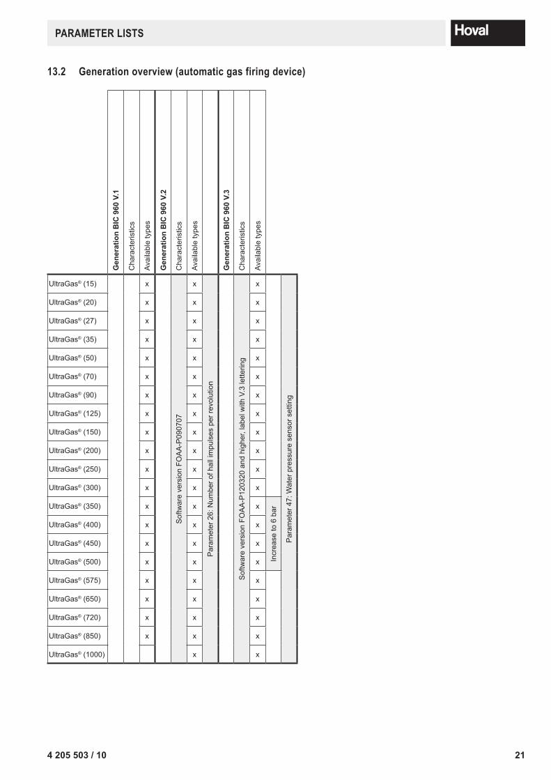
13.2 Generation overview (automatic gas firing device)
Gen
erat
ion
BIC
960
V.1
Cha
ract
eris
tics
Avai
labl
e ty
pes
Gen
erat
ion
BIC
960
V.2
Cha
ract
eris
tics
Avai
labl
e ty
pes
Gen
erat
ion
BIC
960
V.3
Cha
ract
eris
tics
Avai
labl
e ty
pes
UltraGas® (15) x
Sof
twar
e ve
rsio
n FO
AA
-P09
0707
x
Par
amet
er 2
6: N
umbe
r of h
all i
mpu
lses
per
revo
lutio
n
Sof
twar
e ve
rsio
n FO
AA
-P12
0320
and
hig
her,
labe
l with
V.3
lette
ring
xP
aram
eter
47:
Wat
er p
ress
ure
sens
or s
ettin
g
UltraGas® (20) x x x
UltraGas® (27) x x x
UltraGas® (35) x x x
UltraGas® (50) x x x
UltraGas® (70) x x x
UltraGas® (90) x x x
UltraGas® (125) x x x
UltraGas® (150) x x x
UltraGas® (200) x x x
UltraGas® (250) x x x
UltraGas® (300) x x x
UltraGas® (350) x x x
Incr
ease
to 6
bar
UltraGas® (400) x x x
UltraGas® (450) x x x
UltraGas® (500) x x x
UltraGas® (575) x x x
UltraGas® (650) x x x
UltraGas® (720) x x x
UltraGas® (850) x x x
UltraGas® (1000) x x
22 4 205 503 / 10
PARAMeTeR lIsTsPa
ram
eter
Description Uni
t
Leve
l
Fact
ory
setti
ng11
/20/
21 -
UG
(150
)
10/2
0 - U
G (1
5)
10/2
0 - U
G (2
0)
10/2
0 - U
G (2
7)
10/2
0 - U
G (3
5)
10/2
0 - U
G (5
0)
10/2
0 - U
G (7
0)
10/2
0 - U
G (9
0)
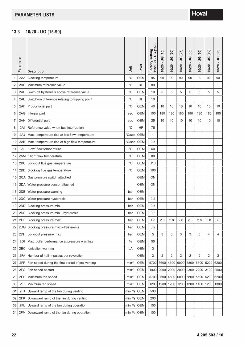
1 2AA Blocking temperature °C OEM 95 90 90 90 90 90 90 90
2 2AC Maximum reference value °C BE 80
3 2AD Swith-off hysteresis above reference value °C OEM 10 5 5 5 5 5 5 5
4 2AE Switch-on difference relating to tripping point °C HF 10
5 2AF Proportional part °C OEM 40 10 10 10 10 10 10 10
6 2AG Integral part sec OEM 100 180 180 180 180 180 180 180
7 2AH Differential part sec OEM 25 10 10 10 10 10 10 10
8 2AI Reference value when bus interruption °C HF 75
9 2AJ Max. temperature rise at low flow temperature °C/sec OEM 1
10 2AK Max. temperature rise at hign flow temperature °C/sec OEM 0.5
11 2AL “Low” flow temperature °C OEM 60
12 2AM “High” flow temperature °C OEM 80
13 2BC Lock-out flue gas temperature °C OEM 110
14 2BD Blocking flue gas temperature °C OEM 100
15 2CA Gas pressure switch attached OEM ON
16 2DA Water pressure sensor attached OEM ON
17 2DB Water pressure warning bar OEM 1
18 2DC Water pressure hysteresis bar OEM 0.2
19 2DD Blocking pressure min. bar OEM 0.5
20 2DE Blocking pressure min – hysteresis bar OEM 0.2
21 2DF Blocking pressure max bar OEM 4.8 2.8 2.8 2.8 2.8 2.8 3.8 3.8
22 2DG Blocking pressure max – hysteresis bar OEM 0.2
23 2DH Lock-out pressure max bar OEM 5 3 3 3 3 3 4 4
24 2DI Max. boiler performance at pressure warning % OEM 50
25 2EC Ionisation warning µA OEM 3
26 2FA Number of hall impulses per revolution OEM 3 2 2 2 2 2 2 2
27 2FF Fan speed during the first period of pre-venting min–1 OEM 5700 3600 4600 6000 5800 5500 5200 6200
28 2FG Fan speed at start min–1 OEM 1900 2000 2000 2000 2300 2200 2100 2500
29 2FH Maximum fan speed min–1 OEM 5700 3600 4600 6000 5800 5500 5200 6200
30 2FI Minimum fan speed min–1 OEM 1200 1200 1200 1200 1300 1400 1200 1300
31 2FJ Upward ramp of the fan during venting min–1/s OEM 500
32 2FK Downward ramp of the fan during venting min–1/s OEM 200
33 2FL Upward ramp of the fan during operation min–1/s OEM 100
34 2FM Downward ramp of the fan during operation min–1/s OEM 100
13.3 10/20 - UG (15-90)
234 205 503 / 10
PARAMeTeR lIsTs
Para
met
er
Description Uni
t
Leve
l
Fact
ory
setti
ng11
/20/
21 -
UG
(150
)
10/2
0 - U
G (1
5)
10/2
0 - U
G (2
0)
10/2
0 - U
G (2
7)
10/2
0 - U
G (3
5)
10/2
0 - U
G (5
0)
10/2
0 - U
G (7
0)
10/2
0 - U
G (9
0)
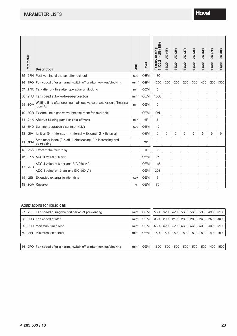
35 2FN Post-venting of the fan after lock-out sec OEM 180
36 2FO Fan speed after a normal switch-off or after lock-out/blocking min–1 OEM 1200 1200 1200 1200 1300 1400 1200 1300
37 2FR Fan-afterrun-time after operation or blocking min OEM 3
38 2FU Fan speed at boiler-freeze-protection min–1 OEM 1500
39 2GA Waiting time after opening main gas valve or activation of heating room fan min OEM 0
40 2GB External main gas valve/ heating room fan available OEM ON
41 2HA Afterrun heating pump or shut-off valve min HF 5
42 2HD Summer operation (“summer kick”) sec OEM 10
43 2IA Ignition (0-> Internal, 1-> Internal + External, 2-> External) OEM 2 0 0 0 0 0 0 0
44 2KM Step modulation (0-> off, 1->increasing, 2-> increasing and decreasing) HF 1
45 2LA Effect of the fault relay HF 2
46 2NA ADC/4-value at 0 bar OEM 25
47 2NBADC/4 value at 6 bar and BIC 960 V.2 OEM 145
ADC/4 value at 10 bar and BIC 960 V.3 OEM 225
48 2IB Extended external ignition time sek OEM 8
49 2QA Reserve % OEM 70
Adaptations for liquid gas27 2FF Fan speed during the first period of pre-venting min–1 OEM 5500 3200 4200 5600 5600 5300 4900 6100
28 2FG Fan speed at start min–1 OEM 3300 2000 2100 2800 2800 2600 2500 3000
29 2FH Maximum fan speed min–1 OEM 5500 3200 4200 5600 5600 5300 4900 6100
30 2FI Minimum fan speed min–1 OEM 1600 1500 1500 1500 1500 1500 1400 1500
36 2FO Fan speed after a normal switch-off or after lock-out/blocking min–1 OEM 1600 1500 1500 1500 1500 1500 1400 1500
24 4 205 503 / 10
PARAMeTeR lIsTs
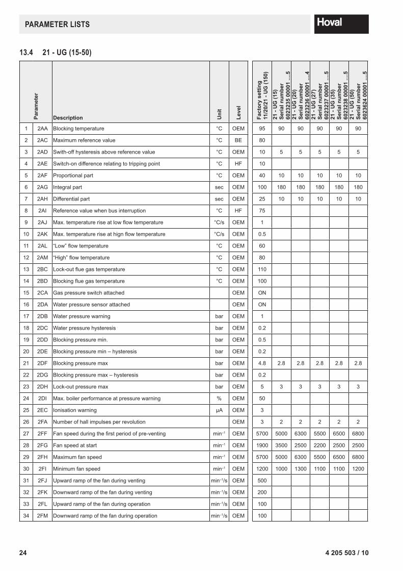
13.4 21 - UG (15-50)
Para
met
er
Description Uni
t
Leve
l
Fact
ory
setti
ng11
/20/
21 -
UG
(150
)
21 -
UG
(15)
Seria
l num
ber
6023
235
0000
1 ...
.521
- U
G (2
0)Se
rial n
umbe
r60
2323
6 00
001
....4
21 -
UG
(27)
Seria
l num
ber
6023
237
0000
1 ...
.521
- U
G (3
5)Se
rial n
umbe
r60
2323
8 00
001
....5
21 -
UG
(50)
Seria
l num
ber
6023
624
0000
1 ...
.5
1 2AA Blocking temperature °C OEM 95 90 90 90 90 90
2 2AC Maximum reference value °C BE 80
3 2AD Swith-off hysteresis above reference value °C OEM 10 5 5 5 5 5
4 2AE Switch-on difference relating to tripping point °C HF 10
5 2AF Proportional part °C OEM 40 10 10 10 10 10
6 2AG Integral part sec OEM 100 180 180 180 180 180
7 2AH Differential part sec OEM 25 10 10 10 10 10
8 2AI Reference value when bus interruption °C HF 75
9 2AJ Max. temperature rise at low flow temperature °C/s OEM 1
10 2AK Max. temperature rise at hign flow temperature °C/s OEM 0.5
11 2AL “Low” flow temperature °C OEM 60
12 2AM “High” flow temperature °C OEM 80
13 2BC Lock-out flue gas temperature °C OEM 110
14 2BD Blocking flue gas temperature °C OEM 100
15 2CA Gas pressure switch attached OEM ON
16 2DA Water pressure sensor attached OEM ON
17 2DB Water pressure warning bar OEM 1
18 2DC Water pressure hysteresis bar OEM 0.2
19 2DD Blocking pressure min. bar OEM 0.5
20 2DE Blocking pressure min – hysteresis bar OEM 0.2
21 2DF Blocking pressure max bar OEM 4.8 2.8 2.8 2.8 2.8 2.8
22 2DG Blocking pressure max – hysteresis bar OEM 0.2
23 2DH Lock-out pressure max bar OEM 5 3 3 3 3 3
24 2DI Max. boiler performance at pressure warning % OEM 50
25 2EC Ionisation warning µA OEM 3
26 2FA Number of hall impulses per revolution OEM 3 2 2 2 2 2
27 2FF Fan speed during the first period of pre-venting min–1 OEM 5700 5000 6300 5500 6500 6800
28 2FG Fan speed at start min–1 OEM 1900 3500 2500 2200 2500 2500
29 2FH Maximum fan speed min–1 OEM 5700 5000 6300 5500 6500 6800
30 2FI Minimum fan speed min–1 OEM 1200 1000 1300 1100 1100 1200
31 2FJ Upward ramp of the fan during venting min–1/s OEM 500
32 2FK Downward ramp of the fan during venting min–1/s OEM 200
33 2FL Upward ramp of the fan during operation min–1/s OEM 100
34 2FM Downward ramp of the fan during operation min–1/s OEM 100
254 205 503 / 10
PARAMeTeR lIsTs
Para
met
er
Description Uni
t
Leve
l
Fact
ory
setti
ng11
/20/
21 -
UG
(150
)
21 -
UG
(15)
Seria
l num
ber
6023
235
0000
1 ...
.521
- U
G (2
0)Se
rial n
umbe
r60
2323
6 00
001
....4
21 -
UG
(27)
Seria
l num
ber
6023
237
0000
1 ...
.521
- U
G (3
5)Se
rial n
umbe
r60
2323
8 00
001
....5
21 -
UG
(50)
Seria
l num
ber
6023
624
0000
1 ...
.5
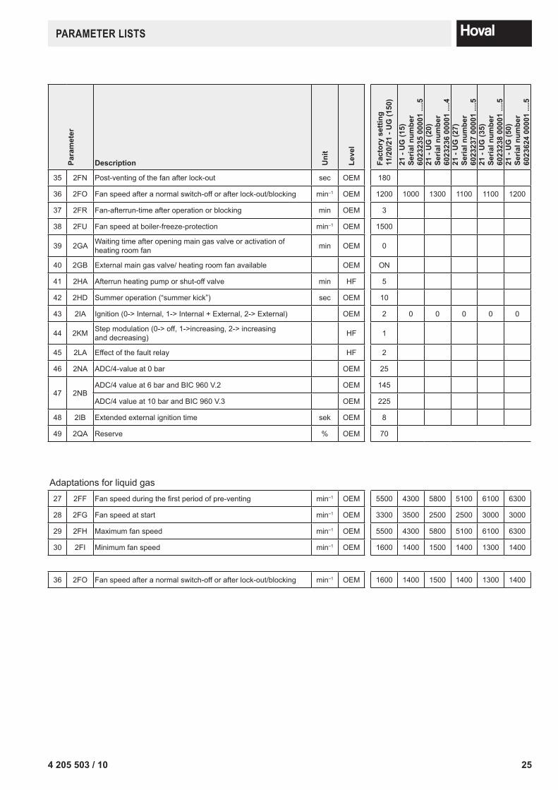
35 2FN Post-venting of the fan after lock-out sec OEM 180
36 2FO Fan speed after a normal switch-off or after lock-out/blocking min–1 OEM 1200 1000 1300 1100 1100 1200
37 2FR Fan-afterrun-time after operation or blocking min OEM 3
38 2FU Fan speed at boiler-freeze-protection min–1 OEM 1500
39 2GA Waiting time after opening main gas valve or activation of heating room fan min OEM 0
40 2GB External main gas valve/ heating room fan available OEM ON
41 2HA Afterrun heating pump or shut-off valve min HF 5
42 2HD Summer operation (“summer kick”) sec OEM 10
43 2IA Ignition (0-> Internal, 1-> Internal + External, 2-> External) OEM 2 0 0 0 0 0
44 2KM Step modulation (0-> off, 1->increasing, 2-> increasingand decreasing) HF 1
45 2LA Effect of the fault relay HF 2
46 2NA ADC/4-value at 0 bar OEM 25
47 2NBADC/4 value at 6 bar and BIC 960 V.2 OEM 145
ADC/4 value at 10 bar and BIC 960 V.3 OEM 225
48 2IB Extended external ignition time sek OEM 8
49 2QA Reserve % OEM 70
Adaptations for liquid gas27 2FF Fan speed during the first period of pre-venting min–1 OEM 5500 4300 5800 5100 6100 6300
28 2FG Fan speed at start min–1 OEM 3300 3500 2500 2500 3000 3000
29 2FH Maximum fan speed min–1 OEM 5500 4300 5800 5100 6100 6300
30 2FI Minimum fan speed min–1 OEM 1600 1400 1500 1400 1300 1400
36 2FO Fan speed after a normal switch-off or after lock-out/blocking min–1 OEM 1600 1400 1500 1400 1300 1400
26 4 205 503 / 10
PARAMeTeR lIsTs
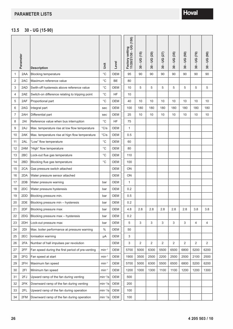
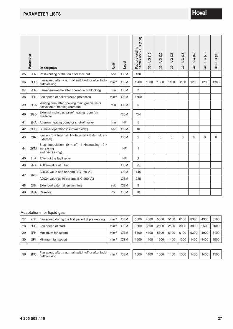
13.5 30 - UG (15-90)
Para
met
er
Description Uni
t
Leve
l
Fact
ory
setti
ng11
/20/
21/3
0 - U
G (1
50)
30 -
UG
(15)
30 -
UG
(20)
30 -
UG
(27)
30 -
UG
(35)
30 -
UG
(50)
30 -
UG
(70)
30 -
UG
(90)
1 2AA Blocking temperature °C OEM 95 90 90 90 90 90 90 90
2 2AC Maximum reference value °C BE 80
3 2AD Swith-off hysteresis above reference value °C OEM 10 5 5 5 5 5 5 5
4 2AE Switch-on difference relating to tripping point °C HF 10
5 2AF Proportional part °C OEM 40 10 10 10 10 10 10 10
6 2AG Integral part sec OEM 100 180 180 180 180 180 180 180
7 2AH Differential part sec OEM 25 10 10 10 10 10 10 10
8 2AI Reference value when bus interruption °C HF 75
9 2AJ Max. temperature rise at low flow temperature °C/s OEM 1
10 2AK Max. temperature rise at hign flow temperature °C/s OEM 0.5
11 2AL “Low” flow temperature °C OEM 60
12 2AM “High” flow temperature °C OEM 80
13 2BC Lock-out flue gas temperature °C OEM 110
14 2BD Blocking flue gas temperature °C OEM 100
15 2CA Gas pressure switch attached OEM ON
16 2DA Water pressure sensor attached OEM ON
17 2DB Water pressure warning bar OEM 1
18 2DC Water pressure hysteresis bar OEM 0.2
19 2DD Blocking pressure min. bar OEM 0.5
20 2DE Blocking pressure min – hysteresis bar OEM 0.2
21 2DF Blocking pressure max bar OEM 4.8 2.8 2.8 2.8 2.8 2.8 3.8 3.8
22 2DG Blocking pressure max – hysteresis bar OEM 0.2
23 2DH Lock-out pressure max bar OEM 5 3 3 3 3 3 4 4
24 2DI Max. boiler performance at pressure warning % OEM 50
25 2EC Ionisation warning µA OEM 3
26 2FA Number of hall impulses per revolution OEM 3 2 2 2 2 2 2 2
27 2FF Fan speed during the first period of pre-venting min–1 OEM 5700 5000 6300 5500 6500 6800 5200 6200
28 2FG Fan speed at start min–1 OEM 1900 3500 2500 2200 2500 2500 2100 2500
29 2FH Maximum fan speed min–1 OEM 5700 5000 6300 5500 6500 6800 5200 6200
30 2FI Minimum fan speed min–1 OEM 1200 1000 1300 1100 1100 1200 1200 1300
31 2FJ Upward ramp of the fan during venting min–1/s OEM 500
32 2FK Downward ramp of the fan during venting min–1/s OEM 200
33 2FL Upward ramp of the fan during operation min–1/s OEM 100
34 2FM Downward ramp of the fan during operation min–1/s OEM 100
274 205 503 / 10
PARAMeTeR lIsTs
Para
met
er
Description Uni
t
Leve
l
Fact
ory
setti
ng11
/20/
21/3
0 - U
G (1
50)
30 -
UG
(15)
30 -
UG
(20)
30 -
UG
(27)
30 -
UG
(35)
30 -
UG
(50)
30 -
UG
(70)
30 -
UG
(90)
35 2FN Post-venting of the fan after lock-out sec OEM 180
36 2FO Fan speed after a normal switch-off or after lock-out/blocking min–1 OEM 1200 1000 1300 1100 1100 1200 1200 1300
37 2FR Fan-afterrun-time after operation or blocking min OEM 3
38 2FU Fan speed at boiler-freeze-protection min–1 OEM 1500
39 2GA Waiting time after opening main gas valve or activation of heating room fan min OEM 0
40 2GB External main gas valve/ heating room fan available OEM ON
41 2HA Afterrun heating pump or shut-off valve min HF 5
42 2HD Summer operation (“summer kick”) sec OEM 10
43 2IA Ignition (0-> Internal, 1-> Internal + External, 2-> External) OEM 2 0 0 0 0 0 0 0
44 2KMStep modulation (0-> off, 1->increasing, 2-> increasingand decreasing)
HF 1
45 2LA Effect of the fault relay HF 2
46 2NA ADC/4-value at 0 bar OEM 25
47 2NBADC/4 value at 6 bar and BIC 960 V.2 OEM 145
ADC/4 value at 10 bar and BIC 960 V.3 OEM 225
48 2IB Extended external ignition time sek OEM 8
49 2QA Reserve % OEM 70
Adaptations for liquid gas27 2FF Fan speed during the first period of pre-venting min–1 OEM 5500 4300 5800 5100 6100 6300 4900 6100
28 2FG Fan speed at start min–1 OEM 3300 3500 2500 2500 3000 3000 2500 3000
29 2FH Maximum fan speed min–1 OEM 5500 4300 5800 5100 6100 6300 4900 6100
30 2FI Minimum fan speed min–1 OEM 1600 1400 1500 1400 1300 1400 1400 1500
36 2FO Fan speed after a normal switch-off or after lock-out/blocking min–1 OEM 1600 1400 1500 1400 1300 1400 1400 1500
28 4 205 503 / 10
PARAMeTeR lIsTsPa
ram
eter
Description Uni
t
Leve
l
Fact
ory
setti
ng11
/20/
21/3
0 - U
G (1
50)
10 -
UG
(125
)
10 -
UG
(150
)
10 -
UG
(200
)
10 -
UG
(250
)
10 -
UG
(300
)
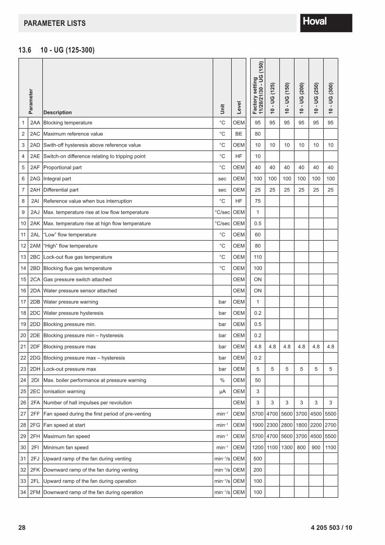
1 2AA Blocking temperature °C OEM 95 95 95 95 95 95
2 2AC Maximum reference value °C BE 80
3 2AD Swith-off hysteresis above reference value °C OEM 10 10 10 10 10 10
4 2AE Switch-on difference relating to tripping point °C HF 10
5 2AF Proportional part °C OEM 40 40 40 40 40 40
6 2AG Integral part sec OEM 100 100 100 100 100 100
7 2AH Differential part sec OEM 25 25 25 25 25 25
8 2AI Reference value when bus interruption °C HF 75
9 2AJ Max. temperature rise at low flow temperature °C/sec OEM 1
10 2AK Max. temperature rise at hign flow temperature °C/sec OEM 0.5
11 2AL “Low” flow temperature °C OEM 60
12 2AM “High” flow temperature °C OEM 80
13 2BC Lock-out flue gas temperature °C OEM 110
14 2BD Blocking flue gas temperature °C OEM 100
15 2CA Gas pressure switch attached OEM ON
16 2DA Water pressure sensor attached OEM ON
17 2DB Water pressure warning bar OEM 1
18 2DC Water pressure hysteresis bar OEM 0.2
19 2DD Blocking pressure min. bar OEM 0.5
20 2DE Blocking pressure min – hysteresis bar OEM 0.2
21 2DF Blocking pressure max bar OEM 4.8 4.8 4.8 4.8 4.8 4.8
22 2DG Blocking pressure max – hysteresis bar OEM 0.2
23 2DH Lock-out pressure max bar OEM 5 5 5 5 5 5
24 2DI Max. boiler performance at pressure warning % OEM 50
25 2EC Ionisation warning µA OEM 3
26 2FA Number of hall impulses per revolution OEM 3 3 3 3 3 3
27 2FF Fan speed during the first period of pre-venting min–1 OEM 5700 4700 5600 3700 4500 5500
28 2FG Fan speed at start min–1 OEM 1900 2300 2800 1800 2200 2700
29 2FH Maximum fan speed min–1 OEM 5700 4700 5600 3700 4500 5500
30 2FI Minimum fan speed min–1 OEM 1200 1100 1300 800 900 1100
31 2FJ Upward ramp of the fan during venting min–1/s OEM 500
32 2FK Downward ramp of the fan during venting min–1/s OEM 200
33 2FL Upward ramp of the fan during operation min–1/s OEM 100
34 2FM Downward ramp of the fan during operation min–1/s OEM 100
13.6 10 - UG (125-300)

294 205 503 / 10
PARAMeTeR lIsTs
Para
met
er
Description Uni
t
Leve
l
Fact
ory
setti
ng11
/20/
21/3
0 - U
G (1
50)
10 -
UG
(125
)
10 -
UG
(150
)
10 -
UG
(200
)
10 -
UG
(250
)
10 -
UG
(300
)
35 2FN Post-venting of the fan after lock-out sec OEM 180
36 2FO Fan speed after a normal switch-off or after lock-out/blocking min–1 OEM 1200 1100 1300 800 900 1100
37 2FR Fan-afterrun-time after operation or blocking min OEM 3
38 2FU Fan speed at boiler-freeze-protection min–1 OEM 1500
39 2GA Waiting time after opening main gas valve or activation of heating room fan min OEM 0
40 2GB External main gas valve/ heating room fan available OEM ON
41 2HA Afterrun heating pump or shut-off valve min HF 5
42 2HD Summer operation (“summer kick”) sec OEM 10
43 2IA Ignition (0-> Internal, 1-> Internal + External, 2-> External) OEM 2 2 2 2 2 2
44 2KM Step modulation (0-> off, 1->increasing, 2-> increasing and decreasing) HF 1
45 2LA Effect of the fault relay HF 2
46 2NA ADC/4-value at 0 bar OEM 25
47 2NBADC/4 value at 6 bar and BIC 960 V.2 OEM 145
ADC/4 value at 10 bar and BIC 960 V.3 OEM 225
48 2IB Extended external ignition time sek OEM 8
49 2QA Reserve % OEM 70
Adaptations for liquid gas27 2FF Fan speed during the first period of pre-venting min–1 OEM 5500 4700 5500 3700 4500 5200
28 2FG Fan speed at start min–1 OEM 3300 2800 3300 2200 2700 3100
29 2FH Maximum fan speed min–1 OEM 5500 4700 5500 3700 4500 5200
30 2FI Minimum fan speed min–1 OEM 1600 1400 1600 1300 1400 1400
36 2FO Fan speed after a normal switch-off or after lock-out/blocking min–1 OEM 1600 1400 1600 1300 1400 1400
30 4 205 503 / 10
PARAMeTeR lIsTsPa
ram
eter
Description Uni
t
Leve
l
Fact
ory
setti
ng11
/20/
21/3
0 - U
G (1
50)
10 -
UG
(350
)
10 -
UG
(400
)
10 -
UG
(450
)
10 -
UG
(500
)
10 -
UG
(650
)
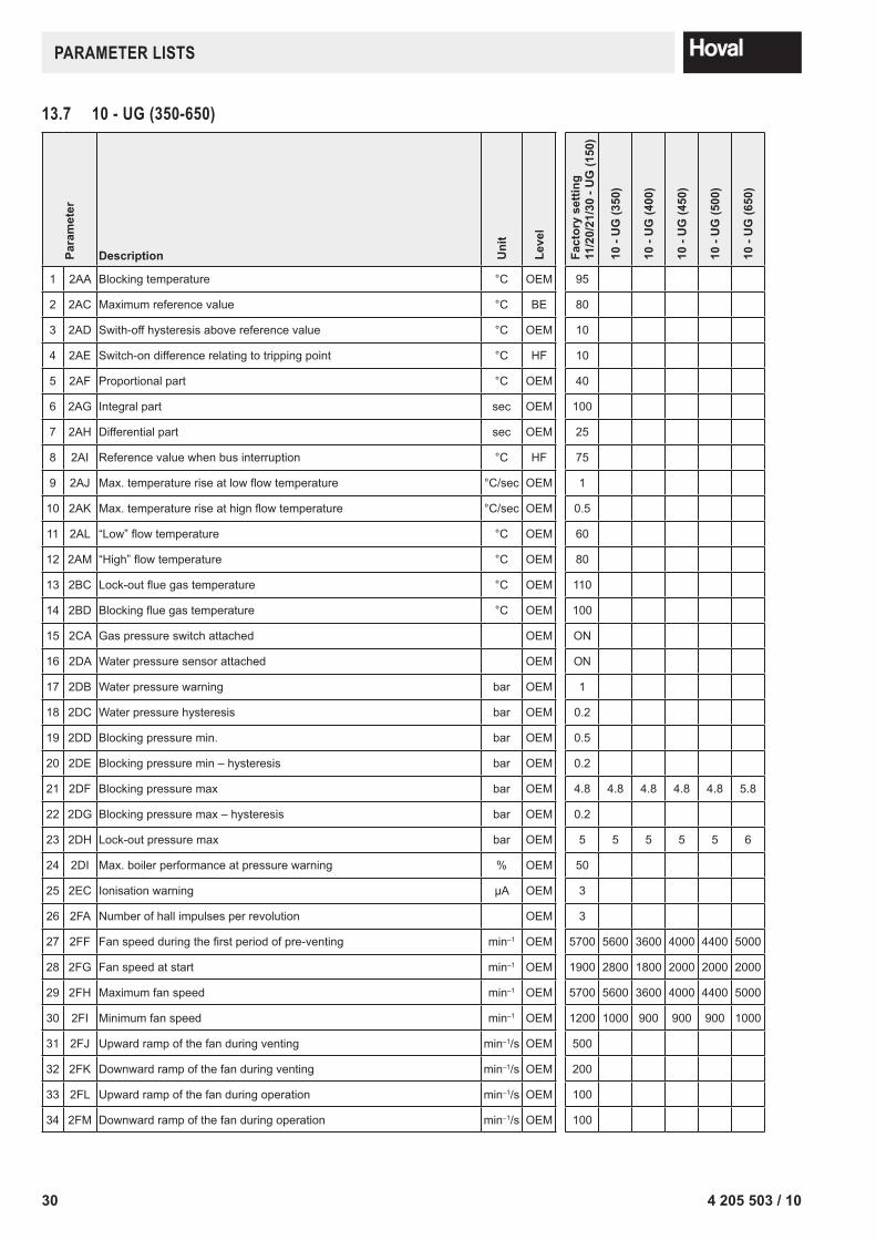
1 2AA Blocking temperature °C OEM 95
2 2AC Maximum reference value °C BE 80
3 2AD Swith-off hysteresis above reference value °C OEM 10
4 2AE Switch-on difference relating to tripping point °C HF 10
5 2AF Proportional part °C OEM 40
6 2AG Integral part sec OEM 100
7 2AH Differential part sec OEM 25
8 2AI Reference value when bus interruption °C HF 75
9 2AJ Max. temperature rise at low flow temperature °C/sec OEM 1
10 2AK Max. temperature rise at hign flow temperature °C/sec OEM 0.5
11 2AL “Low” flow temperature °C OEM 60
12 2AM “High” flow temperature °C OEM 80
13 2BC Lock-out flue gas temperature °C OEM 110
14 2BD Blocking flue gas temperature °C OEM 100
15 2CA Gas pressure switch attached OEM ON
16 2DA Water pressure sensor attached OEM ON
17 2DB Water pressure warning bar OEM 1
18 2DC Water pressure hysteresis bar OEM 0.2
19 2DD Blocking pressure min. bar OEM 0.5
20 2DE Blocking pressure min – hysteresis bar OEM 0.2
21 2DF Blocking pressure max bar OEM 4.8 4.8 4.8 4.8 4.8 5.8
22 2DG Blocking pressure max – hysteresis bar OEM 0.2
23 2DH Lock-out pressure max bar OEM 5 5 5 5 5 6
24 2DI Max. boiler performance at pressure warning % OEM 50
25 2EC Ionisation warning µA OEM 3
26 2FA Number of hall impulses per revolution OEM 3
27 2FF Fan speed during the first period of pre-venting min–1 OEM 5700 5600 3600 4000 4400 5000
28 2FG Fan speed at start min–1 OEM 1900 2800 1800 2000 2000 2000
29 2FH Maximum fan speed min–1 OEM 5700 5600 3600 4000 4400 5000
30 2FI Minimum fan speed min–1 OEM 1200 1000 900 900 900 1000
31 2FJ Upward ramp of the fan during venting min–1/s OEM 500
32 2FK Downward ramp of the fan during venting min–1/s OEM 200
33 2FL Upward ramp of the fan during operation min–1/s OEM 100
34 2FM Downward ramp of the fan during operation min–1/s OEM 100
13.7 10 - UG (350-650)
314 205 503 / 10
PARAMeTeR lIsTs
Para
met
er
Description Uni
t
Leve
l
Fact
ory
setti
ng11
/20/
21/3
0 - U
G (1
50)
10 -
UG
(350
)
10 -
UG
(400
)
10 -
UG
(450
)
10 -
UG
(500
)
10 -
UG
(650
)
35 2FN Post-venting of the fan after lock-out sec OEM 180
36 2FO Fan speed after a normal switch-off or after lock-out/blocking min–1 OEM 1200 1000 900 900 900 1000
37 2FR Fan-afterrun-time after operation or blocking min OEM 3
38 2FU Fan speed at boiler-freeze-protection min–1 OEM 1500
39 2GA Waiting time after opening main gas valve or activation of heating room fan min OEM 0
40 2GB External main gas valve/ heating room fan available OEM ON
41 2HA Afterrun heating pump or shut-off valve min HF 5
42 2HD Summer operation (“summer kick”) sec OEM 10
43 2IA Ignition (0-> Internal, 1-> Internal + External, 2-> External) OEM 2
44 2KM Step modulation (0-> off, 1->increasing, 2-> increasing and decreasing) HF 1
45 2LA Effect of the fault relay HF 2
46 2NA ADC/4-value at 0 bar OEM 25
47 2NBADC/4 value at 6 bar and BIC 960 V.2 OEM 145
ADC/4 value at 10 bar and BIC 960 V.3 OEM 225
48 2IB Extended external ignition time sek OEM 8
49 2QA Reserve % OEM 70
Adaptations for liquid gas27 2FF Fan speed during the first period of pre-venting min–1 OEM 5500 5400 3300 3700 4100 4700
28 2FG Fan speed at start min–1 OEM 3300 3200 1500 1600 1700 1900
29 2FH Maximum fan speed min–1 OEM 5500 5400 3300 3700 4100 4700
30 2FI Minimum fan speed min–1 OEM 1600 1300 1300 1300 1300 1400
36 2FO Fan speed after a normal switch-off or after lock-out/blocking min–1 OEM 1600 1300 1300 1300 1300 1400
32 4 205 503 / 10
PARAMeTeR lIsTsPa
ram
eter
Description Uni
t
Leve
l
Wer
ksei
nste
llung
11/2
0/21
/30
- UG
(150
)
11/2
0/21
/30
- UG
(125
)
11/2
0/21
/30
- UG
(200
)
11/2
0/21
/30
- UG
(250
)
11/2
0/21
/30
- UG
(300
)
11/2
0/21
/30
- UG
(350
)
11/2
0/21
/30
- UG
(400
)
1 2AA Blocking temperature °C OEM 95
2 2AC Maximum reference value °C BE 80
3 2AD Swith-off hysteresis above reference value °C OEM 10
4 2AE Switch-on difference relating to tripping point °C HF 10
5 2AF Proportional part °C OEM 40
6 2AG Integral part sec OEM 100
7 2AH Differential part sec OEM 25
8 2AI Reference value when bus interruption °C HF 75
9 2AJ Max. temperature rise at low flow temperature °C/sec OEM 1
10 2AK Max. temperature rise at hign flow temperature °C/sec OEM 0.5
11 2AL “Low” flow temperature °C OEM 60
12 2AM “High” flow temperature °C OEM 80
13 2BC Lock-out flue gas temperature °C OEM 110
14 2BD Blocking flue gas temperature °C OEM 100
15 2CA Gas pressure switch attached OEM ON
16 2DA Water pressure sensor attached OEM ON
17 2DB Water pressure warning bar OEM 1
18 2DC Water pressure hysteresis bar OEM 0.2
19 2DD Blocking pressure min. bar OEM 0.5
20 2DE Blocking pressure min – hysteresis bar OEM 0.2
21 2DF Blocking pressure max bar OEM 4.8 4.8 4.8 4.8 4.8 5.8 5.8
22 2DG Blocking pressure max – hysteresis bar OEM 0.2
23 2DH Lock-out pressure max bar OEM 5 5 5 5 5 6 6
24 2DI Max. boiler performance at pressure warning % OEM 50
25 2EC Ionisation warning µA OEM 3
26 2FA Number of hall impulses per revolution OEM 3
27 2FF Fan speed during the first period of pre-venting min–1 OEM 5700 4800 3900 4800 5700 5600 3600
28 2FG Fan speed at start min–1 OEM 1900 1600 1300 1600 1900 1900 1200
29 2FH Maximum fan speed min–1 OEM 5700 4800 3900 4800 5700 5600 3600
30 2FI Minimum fan speed min–1 OEM 1200 1100 900 1000 1100 1000 900
31 2FJ Upward ramp of the fan during venting min–1/s OEM 500
32 2FK Downward ramp of the fan during venting min–1/s OEM 200
33 2FL Upward ramp of the fan during operation min–1/s OEM 100
34 2FM Downward ramp of the fan during operation min–1/s OEM 100
13.8 11/20/21/30 - UG (125-400)
334 205 503 / 10
PARAMeTeR lIsTs
Para
met
er
Description Uni
t
Leve
l
Wer
ksei
nste
llung
11/2
0/21
/30
- UG
(150
)
11/2
0/21
/30
- UG
(125
)
11/2
0/21
/30
- UG
(200
)
11/2
0/21
/30
- UG
(250
)
11/2
0/21
/30
- UG
(300
)
11/2
0/21
/30
- UG
(350
)
11/2
0/21
/30
- UG
(400
)
35 2FN Post-venting of the fan after lock-out sec OEM 180
36 2FO Fan speed after a normal switch-off or after lock-out/blocking min–1 OEM 1200 1100 900 1000 1100 1000 900
37 2FR Fan-afterrun-time after operation or blocking min OEM 3
38 2FU Fan speed at boiler-freeze-protection min–1 OEM 1500
39 2GA Waiting time after opening main gas valve or activation of heating room fan min OEM 0
40 2GB External main gas valve/ heating room fan available OEM ON
41 2HA Afterrun heating pump or shut-off valve min HF 5
42 2HD Summer operation (“summer kick”) sec OEM 10
43 2IA Ignition (0-> Internal, 1-> Internal + External, 2-> External) OEM 2
44 2KM Step modulation (0-> off, 1->increasing, 2-> increasing and decreasing) HF 1
45 2LA Effect of the fault relay HF 2
46 2NA ADC/4-value at 0 bar OEM 25
47 2NBADC/4 value at 6 bar and BIC 960 V.2 OEM 145
ADC/4 value at 10 bar and BIC 960 V.3 OEM 225
48 2IB Extended external ignition time sek OEM 8
49 2QA Reserve % OEM 70
Adaptations for liquid gas27 2FF Fan speed during the first period of pre-venting min–1 OEM 5500 4700 3700 4600 5400 5300 3300
28 2FG Fan speed at start min–1 OEM 3300 2800 2200 2700 3200 3100 1600
29 2FH Maximum fan speed min–1 OEM 5500 4700 3700 4600 5400 5300 3300
30 2FI Minimum fan speed min–1 OEM 1600 1400 1300 1400 1400 1300 1300
36 2FO Fan speed after a normal switch-off or after lock-out/blocking min–1 OEM 1600 1400 1300 1400 1400 1300 1300
34 4 205 503 / 10
PARAMeTeR lIsTsPa
ram
eter
Description Uni
t
Leve
l
Fact
ory
setti
ng11
/20/
21 -
UG
(150
)
11/2
0/21
- U
G (4
50)
11/2
0/21
- U
G (5
00)
11/2
0/21
- U
G (5
75)
11/2
0/21
- U
G (6
50)
11/2
0/21
- U
G (7
20)
21 -
UG
(850
)
21 -
UG
(100
0)
1 2AA Blocking temperature °C OEM 95
2 2AC Maximum reference value °C BE 80
3 2AD Swith-off hysteresis above reference value °C OEM 10
4 2AE Switch-on difference relating to tripping point °C HF 10
5 2AF Proportional part °C OEM 40
6 2AG Integral part sec OEM 100
7 2AH Differential part sec OEM 25
8 2AI Reference value when bus interruption °C HF 75
9 2AJ Max. temperature rise at low flow temperature °C/sec OEM 1
10 2AK Max. temperature rise at hign flow temperature °C/sec OEM 0.5
11 2AL “Low” flow temperature °C OEM 60
12 2AM “High” flow temperature °C OEM 80
13 2BC Lock-out flue gas temperature °C OEM 110
14 2BD Blocking flue gas temperature °C OEM 100
15 2CA Gas pressure switch attached OEM ON
16 2DA Water pressure sensor attached OEM ON
17 2DB Water pressure warning bar OEM 1
18 2DC Water pressure hysteresis bar OEM 0.2
19 2DD Blocking pressure min. bar OEM 0.5
20 2DE Blocking pressure min – hysteresis bar OEM 0.2
21 2DF Blocking pressure max bar OEM 4.8 5.8 5.8 5.8 5.8 5.8 5.8 5.8
22 2DG Blocking pressure max – hysteresis bar OEM 0.2
23 2DH Lock-out pressure max bar OEM 5 6 6 6 6 6 6 6
24 2DI Max. boiler performance at pressure warning % OEM 50
25 2EC Ionisation warning µA OEM 3
26 2FA
Number of hall impulses per revolutionfor fan type: G3G250 MW50-11 OEM 3 3 3 3 3 3 3 4
Number of hall impulses per revolutionfor fan type: G3G250 MW00-XB OEM 3 3 3 3 3 3 3 5
27 2FF Fan speed during the first period of pre-venting min–1 OEM 5700 4000 4400 4200 4800 4800 4700 5600
28 2FG Fan speed at start min–1 OEM 1900 1300 1400 1400 1600 1600 1700 1700
29 2FH Maximum fan speed min–1 OEM 5700 4000 4400 4200 4800 4800 4700 5600
30 2FI Minimum fan speed min–1 OEM 1200 900 900 1000 1000 1000 900 1200
31 2FJ Upward ramp of the fan during venting min–1/s OEM 500
32 2FK Downward ramp of the fan during venting min–1/s OEM 200
33 2FL Upward ramp of the fan during operation min–1/s OEM 100
13.9 11/20/21/30 - UG (450-1000)
354 205 503 / 10
PARAMeTeR lIsTs
Para
met
er
Description Uni
t
Leve
l
Fact
ory
setti
ng11
/20/
21 -
UG
(150
)
11/2
0/21
- U
G (4
50)
11/2
0/21
- U
G (5
00)
11/2
0/21
- U
G (5
75)
11/2
0/21
- U
G (6
50)
11/2
0/21
- U
G (7
20)
21 -
UG
(850
)
21 -
UG
(100
0)
34 2FM Downward ramp of the fan during operation min–1/s OEM 100
35 2FN Post-venting of the fan after lock-out sec OEM 180
36 2FO Fan speed after a normal switch-off or after lock-out/blocking min–1 OEM 1200 900 900 1000 1000 1000 900 1200
37 2FR Fan-afterrun-time after operation or blocking min OEM 3
38 2FU Fan speed at boiler-freeze-protection min–1 OEM 1500
39 2GA Waiting time after opening main gas valve or activationof heating room fan min OEM 0
40 2GB External main gas valve/ heating room fan available OEM ON
41 2HA Afterrun heating pump or shut-off valve min HF 5
42 2HD Summer operation (“summer kick”) sec OEM 10
43 2IA Ignition (0-> Internal, 1-> Internal + External, 2-> External) OEM 2
44 2KM Step modulation(0-> off, 1->increasing, 2-> increasing and decreasing) HF 1
45 2LA Effect of the fault relay HF 2
46 2NA ADC/4-value at 0 bar OEM 25
47 2NBADC/4 value at 6 bar and BIC 960 V.2 OEM 145
ADC/4 value at 10 bar and BIC 960 V.3 OEM 225
48 2IB Extended external ignition time sek OEM 8
49 2QA Reserve % OEM 70
Adaptations for liquid gas27 2FF Fan speed during the first period of pre-venting min–1 OEM 5500 3700 4100 3900 4400 4200
on re
ques
t
on re
ques
t28 2FG Fan speed at start min–1 OEM 3300 1700 1800 1800 1800 2000
29 2FH Maximum fan speed min–1 OEM 5500 3700 4100 3900 4400 4200
30 2FI Minimum fan speed min–1 OEM 1600 1300 1300 1400 1400 1500
36 2FO Fan speed after a normal switch-off or after lock-out/blocking min–1 OEM 1600 1300 1300 1400 1400 1500
36 4 205 503 / 10
PARAMeTeR lIsTsPa
ram
eter
Description Uni
t
Leve
l
Fact
ory
setti
ng1
- Com
pact
Gas
® (2
40)
1 - C
ompa
ctG
as® (2
00)
1 - C
ompa
ctG
as® (2
80)
1 2AA Blocking temperature °C OEM 100 100 100
2 2AC Maximum reference value °C BE 85 85 85
3 2AD Swith-off hysteresis above reference value °C OEM 10
4 2AE Switch-on difference relating to tripping point °C HF 10
5 2AF Proportional part °C OEM 20 20 20
6 2AG Integral part sec OEM 100 100 100
7 2AH Differential part sec OEM 0 0 0
8 2AI Reference value when bus interruption °C HF 75
9 2AJ Max. temperature rise at low flow temperature °C/sec OEM 2 2 2
10 2AK Max. temperature rise at high flow temperature °C/sec OEM 1 1 1
11 2AL “Low” flow temperature °C OEM 60
12 2AM “High” flow temperature °C OEM 80
13 2BC Lock-out flue gas temperature °C OEM 110
14 2BD Blocking flue gas temperature °C OEM 100
15 2CA Gas pressure switch attached OEM ON
16 2DA Water pressure sensor attached OEM ON
17 2DB Water pressure warning bar OEM 1
18 2DC Water pressure hysteresis bar OEM 0.2
19 2DD Blocking pressure min. bar OEM 0.5
20 2DE Blocking pressure min – hysteresis bar OEM 0.2
21 2DF Blocking pressure max bar OEM 4.8
22 2DG Blocking pressure max – hysteresis bar OEM 0.2
23 2DH Lock-out pressure max bar OEM 5
24 2DI Max. boiler performance at pressure warning % OEM 50
25 2EC Ionisation warning µA OEM 3
13.10 1 - CompactGas® (200-280)
Attention:The automatic gas firing device BIC 960 which must be used for the CompactGas® boiler does not correspond with the BIC 960 used with the UltraGas® boiler.Therefore when exchanging an automatic gas firing device on a CompactGas®, an article No. 6017 963 must be installed in the ordered BIC 960.Otherwise the locking fault E:02 would be displayed which cannot be acknowledged because no flue gas sensor is installed in the CompactGas®.
Blocking temperature to max. 100°C on request.
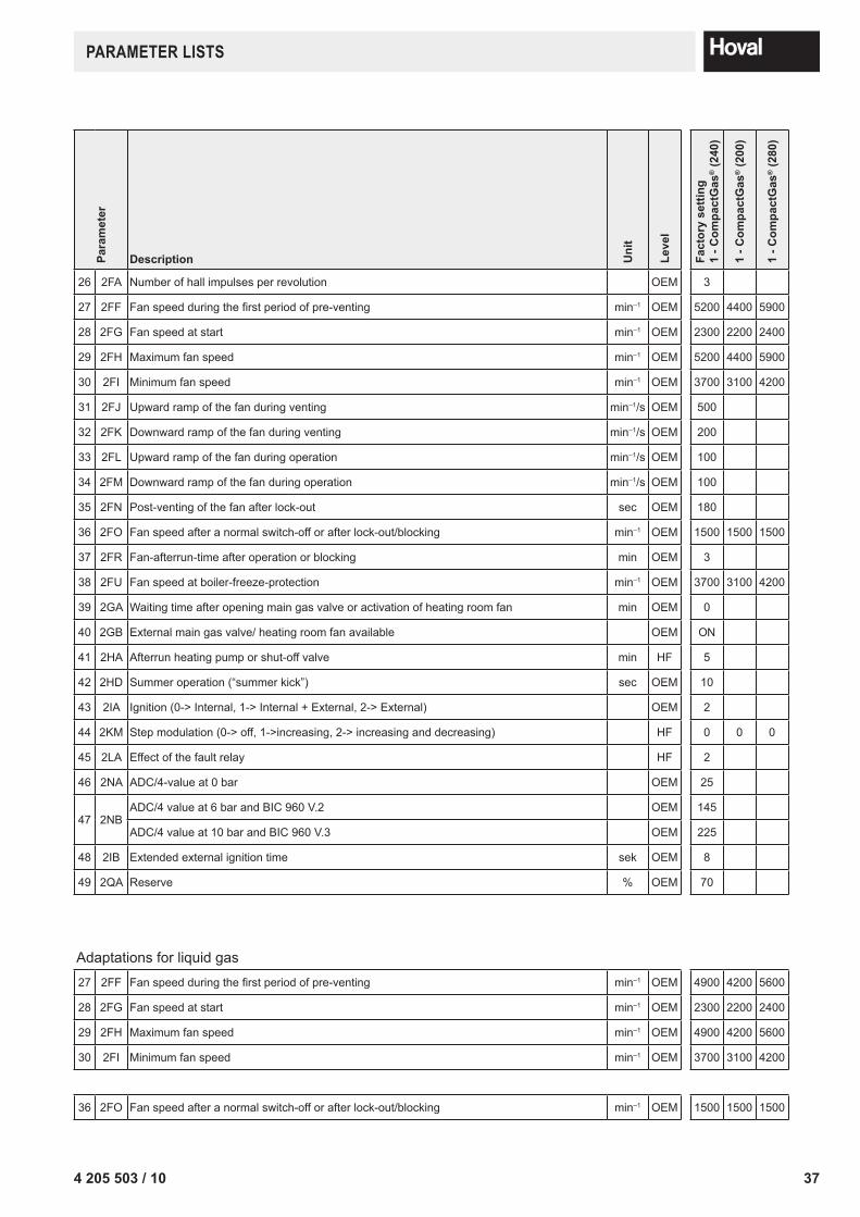
374 205 503 / 10
PARAMeTeR lIsTs
Para
met
er
Description Uni
t
Leve
l
Fact
ory
setti
ng1
- Com
pact
Gas
® (2
40)
1 - C
ompa
ctG
as® (2
00)
1 - C
ompa
ctG
as® (2
80)
26 2FA Number of hall impulses per revolution OEM 3
27 2FF Fan speed during the first period of pre-venting min–1 OEM 5200 4400 5900
28 2FG Fan speed at start min–1 OEM 2300 2200 2400
29 2FH Maximum fan speed min–1 OEM 5200 4400 5900
30 2FI Minimum fan speed min–1 OEM 3700 3100 4200
31 2FJ Upward ramp of the fan during venting min–1/s OEM 500
32 2FK Downward ramp of the fan during venting min–1/s OEM 200
33 2FL Upward ramp of the fan during operation min–1/s OEM 100
34 2FM Downward ramp of the fan during operation min–1/s OEM 100
35 2FN Post-venting of the fan after lock-out sec OEM 180
36 2FO Fan speed after a normal switch-off or after lock-out/blocking min–1 OEM 1500 1500 1500
37 2FR Fan-afterrun-time after operation or blocking min OEM 3
38 2FU Fan speed at boiler-freeze-protection min–1 OEM 3700 3100 4200
39 2GA Waiting time after opening main gas valve or activation of heating room fan min OEM 0
40 2GB External main gas valve/ heating room fan available OEM ON
41 2HA Afterrun heating pump or shut-off valve min HF 5
42 2HD Summer operation (“summer kick”) sec OEM 10
43 2IA Ignition (0-> Internal, 1-> Internal + External, 2-> External) OEM 2
44 2KM Step modulation (0-> off, 1->increasing, 2-> increasing and decreasing) HF 0 0 0
45 2LA Effect of the fault relay HF 2
46 2NA ADC/4-value at 0 bar OEM 25
47 2NBADC/4 value at 6 bar and BIC 960 V.2 OEM 145
ADC/4 value at 10 bar and BIC 960 V.3 OEM 225
48 2IB Extended external ignition time sek OEM 8
49 2QA Reserve % OEM 70
Adaptations for liquid gas27 2FF Fan speed during the first period of pre-venting min–1 OEM 4900 4200 5600
28 2FG Fan speed at start min–1 OEM 2300 2200 2400
29 2FH Maximum fan speed min–1 OEM 4900 4200 5600
30 2FI Minimum fan speed min–1 OEM 3700 3100 4200
36 2FO Fan speed after a normal switch-off or after lock-out/blocking min–1 OEM 1500 1500 1500

Conservation of Energy - Protection of the Environment