automatic generation of language-based tools using the lisa system
TRANSCRIPT

Automatic Generation of Language-based
Tools using the LISA system
Pedro Rangel Henriques a,1 Maria Joao Varanda Pereira b,2,∗
Marjan Mernik c,3 Mitja Lenic c Jeff Gray d Hui Wu d
aUniversity of Minho, Department of Informatics, Portugal
bPolytechnic Institute of Braganca, Portugal
cUniversity of Maribor, Faculty of Electrical Engineering and Computer Science,
Slovenia
dUniversity of Alabama at Birmingham, Department of Computer and
Information Sciences, USA
Abstract
Many tools have been constructed using different formal methods to process var-ious parts of a language specification (e.g., scanner generators, parser generatorsand compiler generators). The automatic generation of a complete compiler wasthe primary goal of such systems, but researchers recognized the possibility thatmany other language-based tools could be generated from formal language specifi-cations. Such tools can be generated automatically whenever they can be describedby a generic fixed part that traverses the appropriate data structures generated by aspecific variable part, which can be systematically derivable from the language spec-ifications. This paper identifies generic and specific parts for various language-basedtools. Several language-based tools are presented in the paper, which are automat-ically generated using an attribute grammar-based compiler generator called LISA.The generated tools that are described in the paper include editors, inspectors,debuggers and visualizers/animators. Because of their complexity of construction,special emphasis is given to visualizers/animators, and the unique contribution ofour approach toward generating such tools.
Key words: attribute grammars, compiler generation, language-based tools,visualizers/animators
Preprint submitted to Elsevier Science 23 November 2004

1 Introduction
The advantages of formal specification of programming language semanticsare well known. First, the meaning of a program is precisely and unambigu-ously defined; second, it offers a unique possibility for automatic generationof compilers or interpreters. Both of these factors contribute to the improve-ment of programming language design and development. The programminglanguages that have been designed with formal methods have improved syn-tax and semantics, less exceptions and are therefore easier to learn. Moreover,from formal language definitions many other language-based tools can be au-tomatically generated, such as: pretty printers, syntax-directed editors, typecheckers, data flow analyzers, partial evaluators, debuggers, profilers, test casegenerators, visualizers, animators, and documentation generators; for a morecomplete list see [1]. In most of these cases the core language definitions haveto be augmented with tool-specific information (e.g., mapping information indebuggers). In other cases, a fragment of formal language definitions (e.g.,regular definitions) is enough for automatic tool generation. It is also possibleto extract implicit information from the formal language definition (e.g., de-pendencies among attributes in semantic functions) in order to automaticallygenerate a tool. The are many benefits of automatically generated language-based tools. Building language-based tools from scratch is time consuming anderror prone, which makes maintenance very costly. This is a serious problemin building language-based tools for domain-specific languages (DSLs). In thecase of DSLs, a compiler/interpreter is usually developed without support forother language-based tools (e.g. debuggers), which are indispensable for pro-grammers. The lack of appropriate tools might even cause newly developedDSLs to become obsolete.
Although previous efforts have explored the concept of automatic generationof language-based tools [2] [3] [4] [1] [5], this paper contributes a more gen-eral approach that identifies generic (fixed) and specific (variable) parts fromwhich language-based tools can be generated automatically from languagespecifications. In many cases, the language specification must be extended,
∗ Corresponding author.Email addresses: [email protected] (Pedro Rangel Henriques), [email protected]
(Maria Joao Varanda Pereira), [email protected] (Marjan Mernik),[email protected] (Mitja Lenic), [email protected] (Jeff Gray),[email protected] (Hui Wu).1 The paper is an extension of already published paper at Workshop on LanguageDescription, Tools and Applications, ENTCS 65, No. 3, 20032 The work of M. Joao is partially supported by the Portuguese program PRODEP,
accao 5.2 da medida 5 – doutoramentos3 The project was supported by Slovenian and Portugal governments under thecontract SLO-P-11/01-04
2

or appropriate information extracted, in order to be able to automaticallygenerate a language-based tool. The paper discusses several tools where thelanguage definition does not need to be extended, such as editors to helpin writing sentences of the language and various inspectors (e.g., automatavisualizers, syntax tree visualizers, and semantic evaluator animators) thatare helpful for a better understanding of the language analysis process. Suchexample tools have all been incorporated in the compiler generator systemcalled LISA [6]. The paper also presents several language tools that requireextensions to a language definition in order to implement a new tool (e.g.,debuggers, algorithm animators and program visualizers).
The main goal of the paper is to show how language-based tools can be au-tomatically generated from an extended language definition in a systematicmanner by identifying generic and specific parts. The approach is presentedin detail for visualizers/animators. Program visualizers/animators are usefultools for deeper and clearer understanding of algorithms, and are valuablefor both programmers and students. Algorithm animators and program vi-sualizers are strongly language and algorithm-oriented, and usually are notdeveloped in a systematic or automatic way. This paper introduces the archi-tecture and implementation of the Alma system, which represents an approachto the automatic generation of animators from extended language definitions.The system has a specific front-end for each language and a generic back-end,and uses a decorated abstract syntax tree (DAST) as the intermediate repre-sentation. In the implementation of Alma the language development systemLISA is used in two different applications. LISA generates the front-end foreach new language, and some parts of it (Java classes) are reused to build theback-end.
The standard definitions about languages and context-free grammars thatmake automatic implementation of programming languages and language-based tools possible can be found in classical textbooks, such as [7]. To specifythe semantics of programming languages, context-free grammars need to beextended. Attribute grammars [8] are a generalization of context-free gram-mars in which each symbol has an associated set of attributes that carrysemantic information, and with each production a set of semantic rules withattribute computation is associated. Attribute grammars have proved to bevery useful in specifying the semantics of programming languages, in auto-matic construction of compilers/interpreters, and in specifying and generat-ing interactive programming environments [9]. The approach presented in thispaper is strongly tied to the power provided by attribute grammars.
The organization of the paper is as follows. Related work is described in section2. Language-based tools that are automatically generated by the LISA systemare described in section 3. The design and implementation of the Alma systemare described in section 4. A summary and concluding remarks are presented
3

in section 5.
2 Related Work
The development of the first compilers in the late fifties without adequatetools was a very complicated and time consuming task. For instance, the im-plementation of the compiler for the programming language FORTRAN tookabout 18 human years [10]. Later on, formal methods, such as operationalsemantics, attribute grammars, denotational semantics, action semantics, al-gebraic semantics, and abstract state machines, were developed. They madethe implementation of programming languages easier and finally contributedto the automatic generation of compilers/interpreters.
Many tools have been built in the past years, based on different formal meth-ods to assist in processing different parts of language specification, such as:scanner generators, parser generators and compiler generators. The automaticgeneration of a complete compiler was the primary goal of such systems. How-ever, researchers soon recognized the possibility that many other language-based tools could be generated from formal language specifications. There-fore, many tools not only automatically generate a compiler but also completelanguage-based environments. Such automatically generated language-basedenvironments include editors, type checkers, debuggers, and various analyz-ers.
For example, FNC-2 [11] is an attribute grammar system that generates ascanner/parser, an incremental attribute evaluator, a pretty printer, and adependency graph visualizer. The CENTAUR system [3] is a generic interac-tive environment which produces a language specific environment from for-mal specifications written in Natural Semantics, a kind of operational seman-tics. The generated environment includes a scanner/parser, a pretty printer, asyntax-directed editor, a type checker, an interpreter and other graphic tools.The SmartTools system [5], a successor of the CENTAUR system, is a devel-opment environment generator that provides a compiler/interpreter, a struc-tured editor and other XML related tools. The ASF+SDF environment [12]generates a scanner/parser, a pretty printer, a syntax-directed editor, a typechecker, an interpreter, and a debugger from algebraic specifications. In theGem-Mex system [4], the formal language is specified with abstract state ma-chines. The generated environment includes a scanner/parser, a type checker,an interpreter, and a debugger. Very similar to the Synthesizer Generator(SGen) [2], the LRC system [13] generates, from high-order attribute gram-mar specifications, an incremental scanner/parser and attribute evaluators,syntax-directed editor, multiple views of the abstract semantic tree (unpars-ing windows), and windows-based interfaces. From the above description of
4

various well known compiler/interpreter generators can be noticed that ed-itors, pretty printers, and type checkers are almost standard tools in suchautomatically generated environments. However, in those papers particularlanguage-based tools are described from the user’s point of view and not howthese tools are actually generated. No systematic treatment of language-basedtool generation has appeared in the literature. In this paper, a systematicapproach is described with specific emphasis on the automatic generation ofvisualizers/animators.
To our knowledge, the only visualizer/animator to be automatically generatedfrom formal specifications is Jitan [14] [15], a visualization environment forconcurrent, object-oriented programming for Java. The CENTAUR system wasused to implement Jitan, where the syntax was specified by the METAL for-malism and the semantics defined by the TYPOL formalism. The authors ofJitan reported that only about ten semantic rules of language specificationsneeded to be equipped with simple extensions. This was possible because theirtwo visualizer engines need to know the existence and status of available ob-jects. In this case, the generic part of the system is enormous and the specificpart is tailored to objects and threads. Even though their approach is specificapproach to automatically generating language-based tools, the approach isquite different from that described in this paper with respect to generic andspecific parts. The Alma system is much more general in this respect and de-sires to have the specific part as big as possible. For example, an Alma userhas all of the power to define the appearance of the visualization (e.g., colorsand lines) through rules.
3 Tools from language definitions generated by the LISA system
LISA is a compiler-compiler, or a system that generates automatically a com-piler/interpreter from attribute grammar based language specifications. Thesyntax and semantics of LISA specifications and its special features (i.e., “tem-plates” and “multiple attribute grammar inheritance”) are described in moredetail in [16]. The use of LISA in generating compilers for real programminglanguages (e.g., PLM, AspectCOOL and COOL, SODL) is reported in [17],[18], [19]. LISA is unique to other attribute-grammar based compiler genera-tors because it employs the “attribute grammar=class” paradigm [9] to enableincremental language development to a greater extent than other approaches.LISA has been used in many projects in combination with newly developedtechnologies and frameworks, such as conversion of parts of LISA specificationsto XML schema and XML schema evolution (e.g., metamodel inference [20]).
To illustrate LISA style, the specification of a simple Robot language is given
5

in Fig. 1. A robot can move in four directions from the initial position (0, 0).After moving, it is stopped in an unknown location, which the user wants tocompute. Often, it is desirable to extend languages like the Robot languagewith new features. For example, it may be desired to know when the robot willreach the final position. Another example of adding a new language featureis the possibility that the robot can move at a different speed. In that casenew syntactic constructs have to be added to the language. The new language(RobotSpeed) is specified (Fig. 2) as an extension to the Robot languageusing multiple attribute grammar inheritance. From these descriptions LISA
automatically generates an interpreter for the RobotSpeed Language.
Additionaly, LISA is capable of generating other language-based tools. In thefollowing subsections four families of such tools are briefly described: editorsto help the final users in the creation and maintenance of the sentences of thespecified language; inspectors that are useful to understand the behavior, or todebug the generated language processor itself; debuggers, which are indispens-able in the debugging process; and visualizers/animators, similar to inspectors,which are useful in understanding the meaning of the source program that isbeing processed.
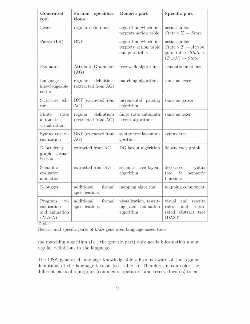
It is important to notice that automatic generation is possible whenever atool can be built from a generic (fixed) part and a specific (variable) part. Anadditional requirement is that the specific part, which is language dependent,has to be systematically derivable from the language specifications. That parthas a well-defined internal representation that can be traversed by the algo-rithms of the generic part. For example, a lexical analyzer uses an algorithmthat interprets an action table [21]. This algorithm is generic and the samefor different languages. However, the action table represents the specific part,and is changed whenever a language specification is modified. Table 1 sum-marizes some of the language-based tools generated by the LISA system. It isnot the aim of this paper to describe all of the algorithms (many of them aredescribed in [21]). The algorithms for program visualization and animationare described in detail in section 4.
However, to show the differences in generic and specific parts and the differ-ences in exploiting language definitions, other language-based tools are brieflyintroduced.
3.1 Editors
Two different LISA generated language oriented editors (i.e., editors that aresensitive to the language lexicon/syntax) are briefly described in this section.
6

language Robot {
lexicon {
Commands left | right | up | down
ReservedWord begin | end
ignore [\0x0D\0x0A\ ] // skip whitespaces
}
attributes int *.inx; int *.iny;
int *.outx; int *.outy;
rule start {
START ::= begin COMMANDS end compute {
START.outx = COMMANDS.outx;
START.outy = COMMANDS.outy;
// robot position in the beginning
COMMANDS.inx = 0;
COMMANDS.iny = 0;};
}
rule moves {
COMMANDS ::= COMMAND COMMANDS compute {
COMMANDS.outx = COMMANDS[1].outx; // propagation of position
COMMANDS.outy = COMMANDS[1].outy; // to sub-commands
COMMAND.inx = COMMANDS.inx;
COMMAND.iny = COMMANDS.iny;
COMMANDS[1].inx = COMMAND.outx;
COMMANDS[1].iny = COMMAND.outy;
}
| epsilon compute {
COMMANDS.outx = COMMANDS.inx;
COMMANDS.outy = COMMANDS.iny; };
}
rule move {
// each COMMAND changes one coordinate
COMMAND ::= left compute {
COMMAND.outx = COMMAND.inx-1;
COMMAND.outy = COMMAND.iny; };
COMMAND ::= right compute {
COMMAND.outx = COMMAND.inx+1;
COMMAND.outy = COMMAND.iny; };
// COMMAND ::= up, COMMAND ::= down are omitted
}
}
Fig. 1. Robot Language
3.1.1 Language Knowledgeable Editors
LISA generates a language knowledgeable editor, which is a compromise be-tween text editors and syntax-directed editors, from formal language specifica-tions. In this case, a language definition does not need to be extended because
7

language RobotSpeed extends Robot {
lexicon {
extends Commands speed
Number [0-9]+
}
attributes int *.inspeed, *.outspeed;
rule extends start {
compute {
// initial position is inherited
START.time = COMMANDS.time;
COMMANDS.inspeed = 1; // beginning speed
START.outspeed = COMMANDS.outspeed; }
}
rule extends moves {
COMMANDS ::= COMMAND COMMANDS compute {
// total time is sum of times spent in sub-commands
COMMANDS[0].time = COMMAND.time + COMMANDS[1].time;
COMMAND.inspeed = COMMANDS[0].inspeed; // speed propagation
COMMANDS[1].inspeed = COMMAND.outspeed; // to sub-commands
COMMANDS[0].outspeed = COMMANDS[1].outspeed; }
| epsilon compute {
COMMANDS.time = 0;
COMMANDS.outspeed = COMMANDS.inspeed; };
}
rule extends move {
// these commands do not change speed
COMMAND ::= left compute {
COMMAND.time = 1.0/COMMAND.inspeed;
COMMAND.outspeed = COMMAND.inspeed; };
COMMAND ::= right compute {
COMMAND.time = 1.0/COMMAND.inspeed;
COMMAND.outspeed = COMMAND.inspeed; };
// COMMAND ::= up, COMMAND ::= down are omitted
}
rule speed {
COMMAND ::= speed #Number compute {
COMMAND.time = 0; // no time is spent for this command
COMMAND.outspeed = Integer.valueOf(#Number.value()).intValue();
// this command does not change the position
COMMAND.outp = COMMAND.inp; };
}
}
Fig. 2. RobotSpeed Language
8
Generated
tool
Formal specifica-
tions
Generic part Specific part
Lexer regular definitions algorithm which in-terprets action table
action table:State × Σ → State
Parser (LR) BNF algorithm which in-terprets action tableand goto table
action table:State × T → Action
goto table: State ×
(T ∪ N) → State
Evaluator Attribute Grammars(AG)
tree walk algorithm semantic functions
Languageknowledgeableeditor
regular definitions(extracted from AG)
matching algorithm same as lexer
Structure edi-tor
BNF (extracted fromAG)
incremental parsingalgorithm
same as parser
Finite stateautomatavisualization
regular definitions(extracted from AG)
finite state automatalayout algorithm
same as lexer
Syntax tree vi-sualization
BNF (extracted fromAG)
syntax tree layout al-gorithm
syntax tree
Dependencygraph visual-ization
extracted from AG DG layout algorithm dependency graph
Semanticevaluatoranimation
extracted from AG semantic tree layoutalgorithm
decorated syntaxtree & semanticfunctions
Debugger additional formalspecifications
mapping algorithm mapping component
Program vi-sualizationand animation(ALMA)
additional formalspecifications
visualization, rewrit-ing and animationalgorithm
visual and rewriterules and deco-rated abstract tree(DAST)
Table 1Generic and specific parts of LISA generated language-based tools
the matching algorithm (i.e., the generic part) only needs information aboutregular definitions in the language.
The LISA generated language knowledgeable editor is aware of the regulardefinitions of the language lexicon (see table 1). Therefore, it can color thedifferent parts of a program (comments, operators, and reserved words) to en-
9

Fig. 3. Language knowledgeable editor
hance understandability and readability of programs. Improved understand-ability is important for programs written in DSLs where end-users are typicallynot programmers but application engineers. Developing such editors for everydifferent DSL is time consuming and costly. The benefits of automaticallygenerated editors are obvious.
In Figure 3 the reserved words, commands and integers in a RobotSpeedprogram are recognized by distinguishing each feature with a different color(e.g., in figure 3 the reserved words are in red).
3.1.2 Syntax-directed Editors
Syntax-directed editors help users to write syntactically correct programs be-fore they are actually compiled, exhibiting the language structure by insertingdirectly the keywords at the correct places (the user only has to fulfill thevariable parts of their text). Syntax-directed editors are aware of the languagesyntax of edited programs and can be automatically generated from a syntaxlanguage definition. LISA currently generates a structured editor from formallanguage specifications. A Structure Editor is a kind of syntax-directed edi-tor, where the syntax structure of written programs are explicitly seen whileediting the program (see Figures 4 and 5 where the selected text is a set ofCOMMANDS in the RobotSpeed language). The language definition is notextended because the incremental parsing algorithm (i.e., the generic part)only needs the information about syntax definitions in the language.
10

Fig. 4. Structure editor
Fig. 5. Syntax tree view
3.2 Inspectors for Language Processors
Inspectors are useful in better understanding how an automatically generatedlanguage compiler/interpreter works. LISA generates the following inspectors:finite state automaton visualizer (useful for better understanding how thelexical analyzer work), syntax tree visualizer (useful for better understandinghow the syntax analyzer work), dependency graph visualizer and semantic treevisualizer. The last two inspectors are briefly introduced in this subsection.
3.2.1 Dependency Graph Visualization
As attribute grammars are specified on the declarative level, the order ofattribute evaluation is determined by the compiler construction tool. Thatsequence is also important for the language designer to understand the actualevaluation order. LISA generates this inspector from information extractedfrom language specifications, which is where the augmented dependency graph(i.e., the specific part) is computed. The augmented dependency graph is usedin an algorithm (i.e., the generic part) for dependency graph layout.
Figure 6 presents an augmented dependency graph that is drawn by theLISA generated tool for the 1st RobotSpeed production. Direct dependen-
11

Fig. 6. Dependency graph view
Fig. 7. Circular dependency graph
cies (e.g., COMMANDS.time → START.time) and indirect dependencies (e.g.,COMMANDS.inx → COMMANDS.outx) are shown in different colors. With the aidof this inspector it is easier to discover why a particular attribute grammaris not absolutely non-circular. Circular attribute grammars are not supportedby LISA and circularity is detected in Fig. 7.
3.2.2 Semantic Evaluator Animation
In attribute grammars a set of attributes carrying semantic information isassociated with each nonterminal. For example, attributes time and outx
are associated with nonterminal COMMANDS in the RobotSpeed language spec-ifications. In the evaluation process the value of these attributes has to becomputed. The semantic analysis is better understood by animating the visitsto the nodes of the semantic tree, and the evaluation of attributes in thesenodes. LISA generates this inspector from semantic functions associated tosyntax rules. The semantic tree layout algorithm (i.e., the generic part) usesa decorated syntax tree and semantic functions, which constitutes the specificparts.
Figure 8 shows a snap-shot of the animation process. The animation of the
12

Fig. 8. Semantic Evaluation view
evaluation process is also very helpful in debugging language specifications.Users can also control the execution by single-stepping and setting the break-points.
Notice the way scalability is addressed: as the tree grows it is impossible toshow all of the picture in the main window. Therefore, a subtree is displayedin the main window and a general picture is shown below (see Fig. 8).
3.3 Debugging Support for DSLs Defined in LISA
Debuggers provide software engineers with an essential tool toward discoveringthe location of program errors. However, development can be difficult when itcomes to the issue of debugging a program written in a DSL, which often re-quires both programming language development expertise and domain knowl-edge. This is due to the fact that a DSL is often translated into some othergeneral purpose language (GPL) and then compiled using the tools availablefor the GPL. Even if the domain expert has knowledge about the underlyingGPL, one line of DSL code may be translated into dozens of lines of GPLcode, which requires knowledge of the code generator in order to understandthe correspondence between the DSL and GPL. As an example, consider thechallenges in debugging parsers generated by tools such as Yacc. In such acase, the benefits provided by the domain idioms are lost because the domainexpert is forced to debug their intention at the GPL level, not at the higherabstraction level provided by the DSL. This sub-section describes the abil-
13

ity to generate debuggers for DSLs defined in LISA. From a DSL grammar,LISA can generate the mapping transformations needed by the DSL DebuggerFramework (DDF) [22], which provides debugging support for DSLs in Eclipse.This allows an end-user or domain expert to debug their DSL program at theproper level of abstraction.
3.3.1 DSL Debugger Generation Processes Overview
An illustrative overview of the DSL debugger generation process is shown inFigure 9. The front-end of the process begins with the generation of a lexerand parser for the DSL. LISA automatically generates the lexer and parserfrom a DSL grammar definition, such as the Robot language grammar defi-nition (shown in Figure 10 of the next section). In addition to the lexer andparser, a mapping generator is needed to link the DSL code to the gener-ated GPL code. The mapping generator is specified as additional semanticactions in the DSL grammar definition. The lexer, parser, and mapping gen-erator form the building blocks for the front-end of the DDF. The back-endof the DDF consists of the stand-alone command line GPL debugger and theEclipse debugger perspective [23]. The Eclipse debugger perspective providesthe graphical interface that is commonly expected in integrated developmentenvironments (IDE). Note that the choice of the GPL debugger depends onthe kind of GPL code generated from the DSL. In the Robot language ex-ample, the generated GPL code is Java, which influenced the choice to usethe Java command line debugger (jdb) [24]. Although this specific examplerepresents a DSL that is translated to Java, the Eclipse debugger platformis independent of the GPL. Thus, LISA and the DDF can be used with anygenerated GPL provided a debugger exists for the GPL.
The semantic actions associated with the debugger use syntax-directed trans-lation and additional semantic functions in the grammar specification to gen-erate the mapping information. In Figure 9, with the mapping generator em-bedded inside the grammar, the lexer and parser generated by LISA (step 1)takes the Robot DSL as input (step 2). LISA not only translates the RobotDSL into the corresponding Robot.java, but also generates the Mapping.javafile (step 3). The mapping file represents a data structure that records all ofthe mapping information about which line of the Robot DSL code is mappedto the corresponding segment of Robot.java code. It indicates the location ofthe Robot.java code segment. Interestingly, the mapping information cross-cuts the grammar in such a way that an aspect emerges within the grammardefinition [25]. The mapping component interacts and bridges the differencesbetween the Eclipse debugger platform and the jdb (step 4). There are tworound-trip mapping processes involved (step 5 and step 6) between the RobotDSL debugging perspective in Eclipse and jdb. A user issues debugging com-mands from the Eclipse that are interpreted into a series of jdb commands
14
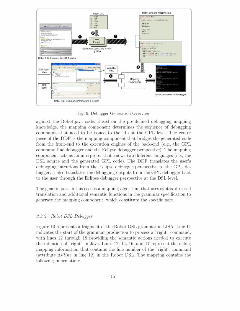
Fig. 9. Debugger Generation Overview
against the Robot.java code. Based on the pre-defined debugging mappingknowledge, the mapping component determines the sequence of debuggingcommands that need to be issued to the jdb at the GPL level. The centerpiece of the DDF is the mapping component that bridges the generated codefrom the front-end to the execution engines of the back-end (e.g., the GPLcommand-line debugger and the Eclipse debugger perspective). The mappingcomponent acts as an interpreter that knows two different languages (i.e., theDSL source and the generated GPL code). The DDF translates the user’sdebugging intentions from the Eclipse debugger perspective to the GPL de-bugger; it also translates the debugging outputs from the GPL debugger backto the user through the Eclipse debugger perspective at the DSL level.
The generic part in this case is a mapping algorithm that uses syntax-directedtranslation and additional semantic functions in the grammar specification togenerate the mapping component, which constitute the specific part.
3.3.2 Robot DSL Debugger
Figure 10 represents a fragment of the Robot DSL grammar in LISA. Line 11indicates the start of the grammar production to process a ”right” command,with lines 12 through 18 providing the semantic actions needed to executethe intention of ”right” in Java. Lines 12, 14, 16, and 17 represent the debugmapping information that contains the line number of the ”right” command(attribute dslline in line 12) in the Robot DSL. The mapping contains thefollowing information:
15

(1) the DSL line number (line 17),(2) the translated Java file name (line 18),(3) the line number of the first line of the corresponding code segment in
Robot.java (attribute gplbegline on line 18),(4) the line number of the last line of the corresponding code segment in
Robot.java (atribute gplendline on line 18).
.
.
.
10 rule move {
11 COMMAND ::= right compute {
12 COMMAND.dslline = COMMAND.indslline + 1;
13 COMMAND.code1 =” x=x+1;// move right”;
14 COMMANDD.gplbegline = COMMAND.ingplbegline;
15 COMMAND.code = COMMAND.code1 + ” time=time+1;”;
16 COMMAND.gplendline = COMMAND.gplbegline + 2;
17 COMMAND.mapcode = ”mapping.add(newMap(” + COMMAND.dslline +
18 ”,\”Robot.java\”,”+ COMMAND.gplbegline + ”,” + COMMAND.gplendline + ”));”; };
19 COMMAND ::= left compute {
20 COMMAND.dslline = COMMAND.indslline + 1;
21 COMMAND.code1 = ” x=x-1;// move left”;
22 COMMANDD.gplbegline = COMMAND.ingplbegline;
23 COMMAND.code = COMMAND.code1 + ” time=time+1;”;
24 COMMAND.gplendline = COMMAND.gplbegline + 2;
25 COMMAND.mapcode = ”mapping.add(newMap(” + COMMAND.dslline +
26 ”,\”Robot.java\”,”+ COMMAND.gplbegline + ”,” + COMMAND.gplendline + ”));”; };
.
.
.
Fig. 10. Robot DSL Grammar in LISA Notation
The jdb responds to the debugger commands sent from the mapping compo-nent. The results from the jdb are sent back to a reverse-mapping component.Because the messages from the jdb are command line outputs, which knownothing of the Robot language and the Eclipse debug platform, it is neces-sary to remap the results back into the Eclipse debugging perspective. TheRobot DSL’s variable Position is displayed in the variables view (see upperright corner of Figure 11). The mapping component translates the messagesback to the Robot DSL through the wrapper interface. The domain expertonly interacts directly with the DSL editor and debugger view at the Robotlanguage level (see left side of Figure 11).
This section demonstrated LISA’s ability to generate programming languagetools inside of the LISA programming environment. Additionally, integrationwith external Integrated Development Environments (IDEs), such as Eclipse,is also possible due to the power of language-based generation.
16

Fig. 11. Robot DSL Debugger Perspective in Eclipse
3.4 Program Visualization and Animation
Another instance of tools that can be derived from formal language specifi-cations are program visualizers/animators. The purpose of such a family oftools is to help the programmer to inspect the data and control flow of asource program—static view of the algorithms realized by the program (visu-alization) —and to understand its behavior—dynamic view of the algorithms’execution (animation). In this section the Alma system is briefly introduced.The front-end ’s that are used by Alma can be constructed using any compilergenerator tool, but in this discussion it will be used as a LISA addon.
For automatic generation of a program visualizer/animator, a language spec-ification needs to be extended with additional information that defines howthe input sentence is converted into the animator’s internal representation(DAST), as shown in Figure 14. Below is an example of such an extension forthe Robot language, where additional steps are added to each command.
language AlmaRobot extends Robot, AlmaBase {
rule start {
START ::= begin COMMANDS end compute {
START.dast = new Alma.CRoot(COMMANDS.tree); };
17

}
rule moves {
COMMANDS ::= COMMAND COMMANDS compute {
COMMANDS[0].tree= new Alma.CStmtsNode(COMMAND.tree,
COMMANDS[1].tree); }
| epsilon compute {
COMMANDS[0].tree = NULL; };
}
rule move {
COMMAND ::= left #Number compute {
COMMAND.tree = new Alma.CLstNode(new Alma.CConstNode("left"),
new Alma.CConstNode(#Number)); };
| COMMAND ::= right #Number compute {
COMMAND.tree = new Alma.CLstNode(new Alma.CConstNode("right"),
new Alma.CConstNode(#Number)); };
...
}
}
The extension shown above illustrates the use of multiple attribute grammarinheritance, which is a standard LISA feature [16]. It is used to specify the at-tribute evaluation related to the DAST construction. From this specification,a parser and a translator are generated that converts each input text into anabstract representation used by the animator, common to all different sourcelanguages. That processor, which is the animator’s front-end, is the languagedependent component of the tool. In this case, its generic part is more complex(described in detail in section 4) than in the cases studied in previous subsec-tions 3.1 and 3.2: it is not just a standard algorithm (we use three languageindependent algorithms), but it requires also two standard data structures (avisual rule base, and a rewriting rule base). Notice that the DAST is languageparadigm dependent. Each node of the DAST is related to concepts defined inthe source program. The visualization of these concepts will assist in under-standing the program.
Consider the following source program in the Robot language:
DOWN 3
RIGHT 7
UP 2
LEFT 4
The animation algorithms can generate a visualization like the one that can beseen in Figure 12. The final layout can be modified by the Alma designer. Drawingprocedures called by the visualizing rules can be changed easily.
18

yi yi yi yi yi
xixi xi xi xi
0 0
3
7 7
1 1
3
2
7
2
4
4
4
0 3
3
7
4
2down
right
right
up
left
up
left
left
up
left
Fig. 12. Robot Operational Animation
Another possible visualization is shown in figure 13.
Fig. 13. Robot Animation
The figure above is more abstract and shows the effect produced by the programin the robot. For this kind of visualization, variable values are not shown like inthe first visualization. Instead, the robot coordinates are used to evaluate each newposition of the robot. The program variables are mapped to robot attributes in aninteresting manner. In this case, it is clear that each x and y of the program will bethe coordinates used to draw the robot. This is not as simple in other cases.
The approach allows the visualization of data structures and can handle proceduresand objects. In these cases, the animation can be achieved with adequate visual-ization rules and drawing procedures. The implementation of the system, which isdiscussed in the next section, has a front-end specific for each language and a genericback-end. The implementation uses a decorated abstract syntax tree (DAST) for theintermediate representation between the front and back ends.
19
Standard Alma Java Classes
Animator
source program
LISA Attribute Grammar
Specification
LISA
Compiler
Visualizer
Rewriter
Animation
front-end back-end
VRB
RRB
DAST
Fig. 14. Architecture of the Alma system
4 Alma Implementation
The Alma system was designed to become a new generic tool for program visual-ization and animation based on the internal representation of the input program inorder to avoid any kind of annotation of the source code (with visual types or state-ments). The system was also designed to be able to handle different programminglanguages.
Alma was conceived as a tool to shield an end-user (a programming beginner, astudent, a teacher) from the concerns of formal specification of the programminglanguage. Visualization and Rewriting rules, which form the core of Alma, dependonly on generic abstract concepts. The mapping of the concrete programming lan-guage constructs into abstract concepts is entirely embedded in the front-end, whichis specific for each language and built just once by a compiler specialist. The front-
end performs the translation task, from the concrete program to Alma’s internalrepresentation, and hides all details from the end-user.
4.1 Alma Architecture
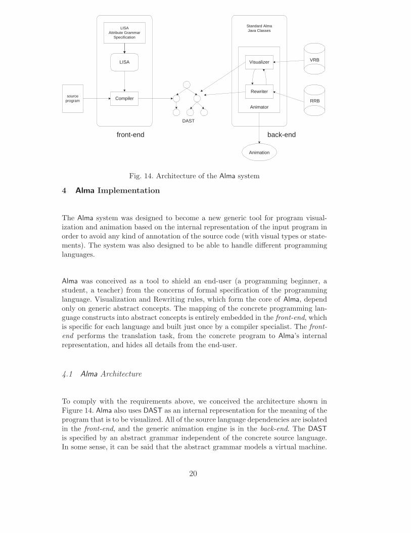
To comply with the requirements above, we conceived the architecture shown inFigure 14. Alma also uses DAST as an internal representation for the meaning of theprogram that is to be visualized. All of the source language dependencies are isolatedin the front-end, and the generic animation engine is in the back-end. The DAST
is specified by an abstract grammar independent of the concrete source language.In some sense, it can be said that the abstract grammar models a virtual machine.
20

The DAST is intended to represent the program state in each moment, and notto reflect directly the source language syntax. In this way we rewrite the DAST todescribe different program states, simulating its execution; notice that we deal witha semantic transformation process, not only a syntactic rewrite.
A Tree Walk Visualizer traverses the tree, creates a visual representation of nodes,and glues figures in order to get the program image at a specific moment. TheDAST is rewritten (to obtain the next internal state) and redrawn to generate a setof images that will constitute the animation of the program. Different visualizationscan be generated from the same DAST depending on the visualization rules.
4.1.1 Visualization in Alma
The visualization is achieved by applying visualization rules (VR) to DAST subtrees.The rules define a mapping between trees and figures and constitutes the specificpart. When the partial figures corresponding to the nodes of a given tree are assem-bled together, a visual representation is obtained for the respective program.
Visualizing Rules
The VRB (Visualizing Rule Base) is a mapping that associates with each attributedtree, defined by a grammar rule (or production), a set of pairs
VRB: DAST 7→ set (cond × dp)
where each pair has a matching condition (cond) and a procedure (dp), whichdefines the tree visual representation. Each cond is a predicate, over attribute valuesassociated with tree nodes, which constrains the use of the drawing procedure (dp);i.e., cond restricts the applicability of the visualizing rule.The written form of each visualizing rule is as follows:
vis_rule(ProdId)= <tree-pattern>,
(condition),
{drawing procedure}
<tree-pattern> = <root, child_1, ..., child_n>
In this template, condition is a boolean expression (by default, evaluates to true)and drawing procedure is a sequence of one or more calls to elementary drawingprocedures.A visualization rule can be applied to all the trees that are instances of the pro-duction ProdId. A tree-pattern is specified using variables to represent each node.Each node has the attributes value, name and type that will be used on the rulespecification, either to formulate the condition, or to pass to the drawing proceduresas parameters.
21

Although each VRB associates to a production a set of pairs, for the sake of sim-plicity its written form only describes one pair. It is possible to have more than onerule for the same production. To illustrate the idea suppose that in Alma’s abstractgrammar a relational operation, rel oper, is defined by the 13th production:
p13: rel_oper : exp exp
where exp is defined as:
p14: exp : CONST
p15: exp : VAR
p16: exp : oper
A visual representation for that relational operation is shown in figure 15.
a.value c.value opr.name ?
a.name c.name
Fig. 15. Visualization of a relational operation
The visualization rules to specify that mapping are written below.
vis_rule(p13) =
<opr,a,c>,
((a.type=exp) AND (c.type=exp)),
{drawRect(a.name,a.value),drawRect(c.name,c.value),
put(opr.name),put(’?’)}
This visualization rule is applied to a three-node tree, which consists of an operatorand two operands. Each operand can be a CONST, VAR or oper (another operation).For each operand, a rectangle is constructed with its value inside and its name asa label of the rectangle. A visual representation of the operation is drawn and theimage is finished with a ? character to identify a relational expression.
Visualization rules are similar to pretty-printers or unparsing facilities in manycompiler generators (e.g., PPML in Centaur [26]). Although unparsing producestext (in many case the text before parsing), visualization rules in Alma are alsoable to produce figures.
Visualization Algorithm
The visualization algorithm (i.e., the generic part) traverses the tree and applies thevisualization rules to the sub-trees rooted in each node according to a bottom-upapproach (post-fix traversal). Using the production identifier of the root node, itobtains the set of possible representations. A drawing procedure is selected depend-ing on the first constraint condition that is true. The algorithm is presented below.
22

visualize(tree){
If not(empty(tree))
then forall t in children(tree) do visualize(t);
rules <- VRB[prodId(tree)]; found <- false;
While (not(empty(rules)) and not(found))
do r <- choice(rules);
rules <- rules - r;
found <- match(tree,r)
If (found) then draw(tree,r); }
A program animation is not the same as code visualization because it depends onthe granularity of the visualization rules. The DAST is an abstract representationof the source code, which assists in applying a visualization rule to each node of thetree (getting a more detailed visualization, usually an operational view like a de-bugger). It is also possible to apply a visualization rule to a set of nodes, or even tothe root. In this last case, the animation is more abstract from a debugger output.We assume that Alma suffers the same problems as other systems that use visuallanguages. Scalability is indeed a problem and care must be taken such that thedrawings used in a visualization help program understanding.
4.1.2 Animation in Alma
Each rewriting rule (RR) specifies a state transition in the process of programexecution and constitutes the specific part. The result of applying the rule is anew DAST obtained by a semantic (may be also a syntactic) change of a sub-tree.This systematic rewriting of the original DAST is interleaved with a sequence ofvisualizations producing an animation. A main function synchronizes the rewritingprocess with the visualization in a parameterized way, allowing for different viewsof the same source program.
Rewriting Rules
The RRB (Rewriting Rule Base) is a mapping that associates a set of tuples witheach tree
RRB: DAST 7→ set(cond × newtree × atribsEval)
where each tuple has a matching condition (cond), a tree (newtree, which definessyntactic transformations), and an attribute evaluation procedure (atribsEval,which defines the changes in the attribute values).The written form of each rewriting rule is as follows:
rule(ProdId)= <tree-pattern>,
(condition),
23

<NewProdId: newtree>,
{attribute evaluation}
<tree-pattern> = <root, child_1, ..., child_n>
<newtree> = <root, child_1, ..., child_n>
In this template, condition is a boolean expression (by default, evaluates to true)and attribute evaluation is a set of statements that defines the new attributevalues (by default, evaluates to skip).A rewriting rule can be applied to all the trees that are instances of the productionProdId. A tree-pattern associates variables to nodes in order to be used in theother fields of the rule specification (i.e., the matching condition, the new tree andthe attribute evaluation). When a variable appears in both the tree-pattern (theleft side of the RR) and the newtree (the right side of the RR), it means that all theinformation contained in that node, including its attributes, will not be modified(i.e., the node is kept in the transformation unchanged).Although each RRB associates to a production a set of tuples, its written form,introduced above, only describes one tuple. It is possible to have more than one rulefor the same production. For instance, consider the following productions, belongingto Alma’s abstract grammar, to define a conditional statement:
p8: IF : cond actions actions
p9: | cond actions
The DAST will be modified using the following rules:
rule(p8) = <if,op,a,b>,
(op.value=true),
<p9:if,op,a>,
{ }
rule(p8) = <if,op,a,b>,
(op.value=false),
<p9:if,op,b>,
{ }
Rewriting Algorithm
The rewriting algorithm (i.e., the generic part) is also a tree-walker that traversesthe tree until a rewriting rule can be applied, or no more rules match the tree nodes(in that case, the transformation process stops). For each node, the algorithm deter-mines the set of possible RR using its production identifier (ProdId) and evaluatesthe contextual condition associated with those rules. The DAST will be modifiedremoving the node that matches the left side of the selected RR and replacing it bythe new tree defined by the right side of that RR. This transformation can be just a
24

semantic modification (only attribute values change), but it can also be a syntacticmodification (some nodes disappear or are replaced).The rewriting algorithm follows:
rewrite(tree){
If not(empty(tree)) then rules <- RRB[prodId(tree)];
found <- false;
While (not(empty(rules)) and not(found))
do r <- choice(rules);
rules <- rules - r;
found <- match(tree,r)
If (found)
then tree <- change(tree,r)
else a <- nextchild(tree)
While (not(empty(a)) and not(rewritten(a)))
do a <- nextchild(tree)
If not(empty(a)) then tree <- rebuild(tree,a,rewrite(a))
return(tree) }
Animation Algorithm
The main function defines the animation process, calling the visualization and therewriting processes repeatedly. The simplest way consists in redrawing the tree aftereach rewriting, but the sequence of images obtained can be very long and may notbe the most interesting. The granularity of the tree redrawing is controlled by afunction, called shownow(), which after each tree’s syntactic-semantic transforma-tion decides if it is necessary to visualize again. The decision is made taking intoaccount the internal state of the animator (that reflects the state of program exe-cution) and the value of user-defined parameters.The animation algorithm, which is the core of Alma’s generic back-end, is as follows:
animate(tree){
visualize(tree);
Do rewrite(tree);
If shownow() then visualize(tree);
until (tree==rewrite(tree)) }
When no more rules can be applied, the output and input of the rewrite functionare the same.
4.2 Alma animation example
In this section, an Alma animation example is presented on a toy imperative languagethat consists of assignment, conditional, repetitive and I/O statements.
25

Fig. 16. Example source program
4.2.1 An example
The example presented in figure 16 has an assignment, a repetitive statement, areading and a writing statement. Figures 17 and 18 show visualizations belongingto an Alma animation. The first one represents the initial state of the program andthe second one shows the first iteration of the cycle. Notice that symbol ---> rep-resents an assignment or an operation (if an arithmetic symbol is under the arrow);the symbol # represents a conditional statement; the symbol @ represents a repeti-tive statement; the symbol =~=>> represents a write and <<=~= a read statement.
We have adopted the original LISA approach to cope with the size of the tree to bedrawn (as noticed in subsection 3.2.2). The approach displays the picture condensedin a small window below the main window with the circle part magnified.
The generality of the system can be a handicap to achieve output effects. The systemwould be more useful if it allows the addition of new rules to support new conceptsor generate different outputs. Alma has a generic part (visualization/animation algo-rithms; tree, nodes, identifier table and rules structure; and rule base interpretation)and a specific part (visualization and rewriting rules, nodes). We conclude that thegeneric part gives generality and the specific part makes it possible to obtain moreadequate visualizations.
26

Fig. 17. Initial state of the program
Fig. 18. The first iteration of the cycle
4.3 Other Alma features
Alma can also cope with different languages, different levels of animation detail,different types of visualizations and different types of paradigms.
27

Different Languages
If we want to apply the system to a different source language, we only have toconstruct a new front-end that defines the concrete syntax of the new language andmaps its main concepts to Alma nodes. This front-end can be generated using LISA.
Different level of animation detail
It is also possible to modify the sampling frequency (number of state transforma-tions before a visualization), or choose the set of nodes we want to visualize, inorder to get a different level of animation detail. An animation can have more orless visualizations depending on the desired detail level. The most detailed anima-tion implies the visualization of the tree after each rewriting. The synchronizationbetween these processes depends on a function called shownow. This function countsthe rewritings and returns 0 or 1 depending on the desired frequency.The visualization is obtained by traversing a DAST that has the associated draw-ings. If we decide to show only some nodes we will get less detail in the visualrepresentation. There are nodes that are more important than others and their vi-sualization can explain all the functionality of the program. It is also possible toaccess an interface to choose the desired nodes and watch the results.It is important to distinguish the animation detail level from the visualization de-tail level. For animation detail, the drawings do not have to change (it is concernedwith process synchronization and the number of visualizations). In visualization de-tail, it is necessary to redefine the visualization rules in order to get different results.
Different types of visualizations
Alma has two bases of rules that can be improved with new semantics or new draw-ings. It may be desired to get different visualizations for the same language usedbefore. Alternatively, it may be desired to animate a very different language, whichwould require the definition of new visualizations. There are several possibilities tochange visualizations: varying the level of visualization detail using a different map-ping between nodes and drawings; choosing different drawings; or both, in order toget a different abstraction level.The generated visualizations are based on rules that map nodes to drawings. If wewant to change the drawings in order to get a different visualization, we can mod-ify rules or specify new ones. The same concepts can be represented with differentdrawings.If we want to change the visualization detail, we must associate the drawings toanother level of nodes. In some cases, the same drawings can be used, but whenthe concepts concerned at this level are different, it is necessary to define anotherdrawing. By changing drawings and associated nodes, it is possible to modify theabstraction level of the visual results. The idea is to create new visualization rulesin order to associate more abstract drawings to higher level nodes.
Different type of paradigms
If there is a very different source language from a different programming paradigm,it is necessary to verify which concepts are common and which are not. For the last
28

ones, new visualization rules must be defined, new DAST nodes must be created,and new semantics must be specified with rewriting rules. This section will brieflyshow an example in Prolog.Consider the following input program:
mother(julie,susan).
mother(susan,john).
father(peter,paul).
father(peter,susan).
parents(M,P,E):-mother(M,E),father(P,E).
A front-end is needed to map the Prolog concepts to Alma nodes. An extendedLISA grammar associates facts and rules to a PROCDEF node, because this noderepresents the definition of a code block that can be invoked from any placeof the program. For each query an execution tree is created.
The animation of the execution tree (simulation of the proof process) uses thevisualization rules already defined for other languages. In a similar way, thesame rewriting rules are used to simulate procedure calls.For example, consider the following query:
? - parents(M,P,susan).
The output can be seen in figure 19, which presents the less detailed versionof the generated animation (the minimal number of steps are shown).Figure 20 shows another kind of visualization for the same program. This vi-sualization is obtained by using other visualization rules.This example illustrates the possibility of reusing the visualization and rewrit-ing rules, already defined in Alma for imperative languages, to animate declar-ative programs (proof processes).These examples assume that Alma will be mainly used in small programs, orwith DSLs for which there are no debugging tools or visualizers. Alma pro-duces graphical representations that usually have problems of scalability andit’s also very difficult to chose the appropriate drawings for better understand-ing. This discussion did not include details on output quality or the systemperformance. The focus of this section was the approach to visualize automat-ically different concepts and different languages using the same DAST-basedapproach.
5 Conclusion
Many applications today are written in well-understood domains. One trendin programming is to provide software tools designed specifically to handle the
29

? Susan
M P
Susan
M P
Susan
Susan
M
P
?
?
?
parents
mother
father
parents
M P
Susan ? parents
?
M P
M ? Susan
? Susan
P
Julie Susan
Peter Susan
Julie Susan
Peter Susan
M
P
M P
Susan parents
Peter Susan Julie parents
mother
mother
mother
father
father
father
Fig. 19. Alma generated animation
Susan
P
Susan
M
Julie Peter
Susan
P
Susan
M
Susan
M P
Julie Peter
Susan
M P
Fig. 20. Another Alma generated animation
development of domain-specific applications in order to greatly simplify theirconstruction. These tools take a high-level description of the specific task andgenerate a complete application.
30

One such well established domain is compiler construction, because there isa long tradition of producing compilers by hand using an underlying theorythat is well understood (supporting all the analysis phases, and even code gen-eration and optimization processes). At present, there exist many generatorsthat automatically produce language-based tools from programming languagespecifications. Although particular automatic generation of language-basedtools was discussed before, in this paper a more general approach is takenby identifying generic and specific parts from which language-based tools canbe generated automatically from language specifications. Previous generatorsvaried widely in what constituted the generic and specific parts. Such classifi-cation can also be a base for comparing systems that automatically generatelanguage-based tools. In order to generate automatically language-base tools,it is often the case that a language specifications needs to be extended or ap-propriate information needs to be extracted. Concrete examples of both types,produced by the generator system LISA, were introduced and discussed in thepaper.
The benefits of automatically generated language-based tools should not beignored. Building language-based tools from scratch (especially for DSLs) istime consuming and error prone, which makes tool maintenance very costly.
6 Acknowledgements
We would like to thank anonymous reviewers for useful comments on earlierversions.
References
[1] J. Heering, P. Klint, Semantics of programming languages: A tool-orientedapproach, ACM Sigplan Notices 35 (3) (2000) 39–48.
[2] T. Reps, T. Teitelbaum, The Synthesizer Generator, ACM SIGPLAN Notices19 (5) (1984) 42–48.
[3] P. Borras, D. Clement, T. Despeyroux, J. Incerpi, G. Kahn, B. Lang,CENTAUR: The system, ACM SIGPLAN Notices 24 (2) (1989) 14–24.
[4] M. Anlauff, P. Kutter, A. Pierantonio, Formal aspects and developmentenvironments for Montages, in: 2nd International Workshop on the Theory andPractice of Algebraic Specifications (ASF+SDF’97), Electronic Workshops inComputing, Springer/British Computer Society, 1997.
31

[5] I. Attali, C. Courbis, P. Degenne, A. Fau, D. Parigot, C. Pasquier, SmartTools:A generator of interactive environments tools, in: 10th International Conferenceon Compiler Construction, Vol. 2027, Lecture Notes in Computer Science,Springer-Verlag, 2001, pp. 355–360.
[6] M. Mernik, M. Lenic, E. Avdicausevic, V. Zumer, LISA: An InteractiveEnvironment for Programming Language Development, in: N. Horspool (Ed.),11th International Conference on Compiler Construction, Vol. 2304, LectureNotes in Computer Science, Springer-Verlag, 2002, pp. 1–4.
[7] J. Hopcroft, J. Ullman, Introduction to Automata Theory, Languages andComputation, Addison-Wesley, Reading, MA, 1979.
[8] D. Knuth, Semantics of contex-free languages, Math. Syst. Theory 2 (2) (1968)127–145.
[9] J. Paakki, Attribute grammar paradigms - a high-level methodology in languageimplementation, ACM Computing Surveys 27 (2) (1995) 196–255.
[10] J. W. Backus, R. J. Beeber, S. Best, R. Goldberg, L. M. Haibt, H. L. Herrick,R. A. Nelson, D. Sayre, P. B. Sheridan, H. Stern, I. Ziller, R. A. Hughes, R. Nutt,The fortran automatic coding system, in: Western Joint Computer Conference,1957, pp. 188–198.
[11] M. Jourdan, D. Parigot, The FNC-2 system user’s guide and reference manual,release 1.19, Tech. rep., INRIA Rocquencourt (1997).
[12] M. van den Brand, A. van Deursen, J. Heering, H. de Jong, M. de Jonge,T. Kuipers, P. Klint, L. Moonen, P. Oliver, J. Scheerder, J. Vinju, E. Visser,J. Visser, The ASF+SDF Meta-environment: A component-based languagedevelopment environment, in: 10th International Conference on CompilerConstruction, Vol. 2027, Lecture Notes in Computer Science, Springer-Verlag,2001, pp. 365–370.
[13] J. Saraiva, M. Kuiper, Lrc - a generator for incremental language-oriented tools,in: 7th International Conference on Compiler Construction, Vol. 1383, LectureNotes in Computer Science, Springer-Verlag, 1998.
[14] I. Attali, D. Caromel, S. O. Ehmety, S. Lippi, Semantic-based visualization forparallel object-oriented programming, ACM SIGPLAN Notices 31 (10) (1996)421–440.
[15] I. Attali, D. Caromel, M. Russo, Graphical visualization of Java objects,threads, and locks, IEEE Distributed Systems Online 2 (1).URL http://dsonline.computer.org/0101/features/att0101 print.htm
[16] M. Mernik, M. Lenic, Enis Avdicausevic, V. Zumer, Multiple AttributeGrammar Inheritance, Informatica 24 (3) (2000) 319–328.
[17] M. Mernik, M. Lenic, E. Avdicausevic, V. Zumer, A reusable object-orientedapproach to formal specifications of programming languages, L’Objet 4 (3)(1998) 273–306.
32

[18] E. Avdicausevic, M. Lenic, M. Mernik, V. Zumer, AspectCOOL: An experimentin design and implementation of aspect-oriented language, ACM SIGPLANNotices 36 (12) (2001) 84–94.
[19] M. Mernik, U. Novak, E. Avdicausevic, M. Lenic, V. Zumer, Design andimplementation of simple object description language, in: ACM Symposiumon Applied Computing, SAC’2001, 2001, pp. 590–594.
[20] F. Javed, M. Mernik, J. Zhang, J. Gray, B. Bryant, Mars: A metamodelrecovery system using grammar inference, Tech. rep., University of Alabamaat Birmingham (2004).
[21] A. V. Aho, R. Sethi, J. D. Ullman, Compilers: Principles, Techniques, and Tools,Addison-Wesley, 1986.
[22] H. Wu, J. Gray, M. Mernik, Debugging domain-specific languages in eclipse, in:Eclipse Technology Exchange Poster Session at OOPSLA 2004, 2004.
[23] D. Wright, B. Freeman-Benson, How to write an eclipse debugger, in: EclipseCorner, Fall 2004, http://www.eclipse.org/articles/index.html.
[24] jdb - the java debugger, available fromhttp://java.sun.com/j2se/1.3/docs/tooldocs/solaris/jdb.html.
[25] H. Wu, J. Gray, S. Roychoudhury, M. Mernik, Weaving a debugging aspectinto domain-specific language grammars, in: ACM Symposium for AppliedComputing (SAC) - Programming for Separation of Concerns Track, To appear,2005.
[26] A centaur tutorial, version 2.0, Tech. rep. (1994).
33